EP0165444B1 - Drive for a waxing device and method for driving such a device - Google Patents
Drive for a waxing device and method for driving such a device Download PDFInfo
- Publication number
- EP0165444B1 EP0165444B1 EP85105735A EP85105735A EP0165444B1 EP 0165444 B1 EP0165444 B1 EP 0165444B1 EP 85105735 A EP85105735 A EP 85105735A EP 85105735 A EP85105735 A EP 85105735A EP 0165444 B1 EP0165444 B1 EP 0165444B1
- Authority
- EP
- European Patent Office
- Prior art keywords
- drive
- waxing
- drive according
- drive belt
- stop
- Prior art date
- Legal status (The legal status is an assumption and is not a legal conclusion. Google has not performed a legal analysis and makes no representation as to the accuracy of the status listed.)
- Expired
Links
- 238000004018 waxing Methods 0.000 title claims description 35
- 238000000034 method Methods 0.000 title claims description 3
- 238000007383 open-end spinning Methods 0.000 claims description 13
- 239000004753 textile Substances 0.000 claims description 8
- 238000004804 winding Methods 0.000 claims description 4
- 239000007787 solid Substances 0.000 claims description 3
- 239000000969 carrier Substances 0.000 claims description 2
- 239000011796 hollow space material Substances 0.000 claims 1
- 239000012188 paraffin wax Substances 0.000 description 54
- 238000009987 spinning Methods 0.000 description 16
- 239000000835 fiber Substances 0.000 description 6
- 230000006835 compression Effects 0.000 description 4
- 238000007906 compression Methods 0.000 description 4
- 230000008901 benefit Effects 0.000 description 2
- 238000010276 construction Methods 0.000 description 2
- 239000002657 fibrous material Substances 0.000 description 2
- 238000009940 knitting Methods 0.000 description 2
- 230000009471 action Effects 0.000 description 1
- 230000005540 biological transmission Effects 0.000 description 1
- 230000008859 change Effects 0.000 description 1
- 230000008878 coupling Effects 0.000 description 1
- 238000010168 coupling process Methods 0.000 description 1
- 238000005859 coupling reaction Methods 0.000 description 1
- 238000006073 displacement reaction Methods 0.000 description 1
- 230000000694 effects Effects 0.000 description 1
- 238000012423 maintenance Methods 0.000 description 1
- 238000011089 mechanical engineering Methods 0.000 description 1
- 230000004048 modification Effects 0.000 description 1
- 238000012986 modification Methods 0.000 description 1
- 230000009467 reduction Effects 0.000 description 1
- 125000006850 spacer group Chemical group 0.000 description 1
- 238000011144 upstream manufacturing Methods 0.000 description 1
- 239000001993 wax Substances 0.000 description 1
Images

Classifications
-
- B—PERFORMING OPERATIONS; TRANSPORTING
- B65—CONVEYING; PACKING; STORING; HANDLING THIN OR FILAMENTARY MATERIAL
- B65H—HANDLING THIN OR FILAMENTARY MATERIAL, e.g. SHEETS, WEBS, CABLES
- B65H71/00—Moistening, sizing, oiling, waxing, colouring or drying filamentary material as additional measures during package formation
- B65H71/005—Oiling, waxing by applying solid wax cake during spooling
-
- B—PERFORMING OPERATIONS; TRANSPORTING
- B65—CONVEYING; PACKING; STORING; HANDLING THIN OR FILAMENTARY MATERIAL
- B65H—HANDLING THIN OR FILAMENTARY MATERIAL, e.g. SHEETS, WEBS, CABLES
- B65H2701/00—Handled material; Storage means
- B65H2701/30—Handled filamentary material
- B65H2701/31—Textiles threads or artificial strands of filaments
Definitions
- the present invention relates to a drive device for a waxing device of a textile machine, which has a multiplicity of similar waxing devices, each of which has a rotatable polygonal bolt which is connected to a drive whorl with which an endless drive belt is engaged, the polygonal bolt receiving a solid waxing body on which a thread to be waxed is supported.
- the solid paraffin body is rotated by the thread fed to a winding device (DE-Gm 7611 630).
- a winding device DE-Gm 7611 630
- an individual drive motor is provided per paraffinizing device (DE-OS 2 316 452).
- the object of the invention is to provide a simple and safe drive device for a paraffinizing device.
- This object is achieved in that the drive belt is in engagement with a plurality of adjacent paraffinizing devices.
- Such a drive is extremely simple.
- this drive has proven to be completely reliable even at the low speeds that are desired for the paraffin body, so that a uniform waxing of the thread is guaranteed even over a long period.
- Drive belts in the sense of the present invention are not only understood to mean flat belts, but all elongate drive elements such as round cords, V-belts, toothed belts, etc. are to be covered herewith.
- the drive belt is zigzagged around the drive whorls of the adjacent paraffinizing devices.
- the drive belt jointly assigned to these waxing devices is thus alternately on the one and on the other side of the common surface, on which the polygonal bolts of these waxing devices are located, in driving connection with the drive whorls of these waxing devices.
- the common surface can be a plane or (in the case of an inclined arrangement of the paraffining devices on round machines) also have a conical shape.
- the drive belt is expediently connected to this shaft in terms of drive.
- This shaft for controlling the fiber delivery is driven as a function of the fiber throughput by the open-end spinning devices, so that the paraffinizing devices are adapted to this throughput and are therefore always driven only at the speed required for this throughput.
- the drive for the paraffinizing devices has a very long service life.
- a particularly simple construction of the subject matter of the invention is made possible if the drive whorl of each paraffinizing device is arranged between a holder for this paraffinizing device and the paraffinizing body. This also leads to particularly good accessibility to this drive. A further reduction in the structural outlay is achieved if the polygonal bolt is formed in one piece with the drive whorl.
- the polygonal bolt is expediently designed as a hollow body which receives the mounting and fastening.
- the fastening has a threaded bolt which is screwed into a threaded bushing provided in the holder.
- the cavity of the polygonal bolt can be closed at its end facing away from the bearing by a cap which projects beyond the outer circumference of the polygonal bolt and is designed as a stop for an elastically loaded paraffin support plate mounted on the polygonal bolt.
- the cap has corners, the polygonal bolt protrudes on its chamfered edges, while the side surfaces of the polygonal bolt and the cap are flush, the paraffin support plate having guide surfaces closely matched to the profile of the polygonal bolt. In this way it is achieved that the paraffin body can be pushed over the insert serving as a stop for the paraffin support plate onto the polygonal bolt without the play between the polygonal bolt and the paraffin body having to be increased.
- a support element for the returning run of the drive belt is preferably provided.
- this support element is advantageously arranged just below this thread tension compensation element, so that the drive belt is protected by this cover.
- the support element serves as a carrier for a stop limiting the advancing movement of the paraffin body.
- a carrier designed as a supporting element is arranged on both sides of the paraffin body, the stop extending from one of these carriers to the other carrier.
- the support element which is arranged in front of the paraffin body with respect to the rotational movement acting on the stop, is expediently designed as a pivot bearing for the stop, while the support element arranged after the paraffin body has a longitudinal slot on its side facing away from the waxing device for receiving the end of the stop having.
- an open channel can be provided for this run on its side facing the paraffinizing device, which in an advantageous embodiment of the subject matter of the invention is formed by the holder and a cover strip, which is an integral part of the thread tension compensation element.
- the invention preferably provides for the rotational speed of the paraffin body to be adapted to the fiber mass fed to the open-end spinning device. This is done, as already mentioned above, preferably in that the drive of the paraffin body is removed directly from the shaft carrying the delivery rollers, but another - e.g. B. electrical - speed coupling also possible in principle.
- the invention provides a simple device that is compact, requires little energy to drive the paraffin body and that works reliably without maintenance. Despite the low mechanical engineering expenditure, the device is durable and user-friendly.
- the invention can be used in various textile machines on which the thread can be waxed.
- the textile machines can have an elongated or a round shape.
- it does not matter whether it is yarn-producing spinning machines, yarn-treating winding machines or yarn-processing machines (knitting or warp knitting machines).
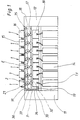
- an open-end spinning machine (FIG. 1) was chosen as an example, which has a large number of spinning positions 1 and, accordingly, paraffinizing devices 2.
- the spinning machine shown has seven spinning positions 1; in practice, however, these are considerably more.
- the spinning machine itself is only shown schematically, all elements which are not absolutely necessary for understanding the invention being omitted for the sake of clarity.
- the open-end spinning machine has an end frame 11 and 12 at each end.
- the spinning machine has one spinning device covered by a cover 10 for each spinning station 1.
- the fiber material 13, which is presented to it in a spinning can 14, is fed to the spinning device with the aid of a delivery device which is driven by a shaft 19 which extends over the entire length of the machine.
- the thread 15 spun in the spinning device is drawn off with the aid of take-off rollers 17 and 18 and wound onto a bobbin 16, the thread 15 being presented to the bobbin 16 in an alternating manner in the usual and therefore not shown manner.
- a paraffin device 2 is arranged in the thread path between the take-off rollers 17 and 18 and the bobbin 16 (or a yarn processing point in yarn processing Machines.
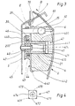
- Each waxing device 2 has a polygonal bolt 4 (FIG. 2), on which a waxing body 21 for waxing the thread 15 is attached.
- the polygonal bolt 4 is connected in terms of drive to a drive whorl 20.
- the drive whorls 20 of the paraffinizing devices 2 of a large number of adjacent spinning positions 1 are driven by a common drive belt 3.
- the drive belt 3 can always rest on one and the same side on the drive whorls 20 (FIG. 2) of the paraffinizing devices 2, the drive belt 3 being tensioned by conventional tensioning rollers, not shown, and held in contact with the drive whorls 20.
- the paraffin bodies 21 are driven uniformly in this way. Even if the moment exerted by the thread 15 on the paraffin body 21 changes briefly as a result of changes in the thread tension, a change in the rotational speed that is not so great that could impair the perfect waxing of the thread 15 is nevertheless achieved. Rather, it has been shown that the waxing of the thread 15 and the processing of the paraffin body 21 takes place very uniformly.
- FIG. 1 A particularly advantageous embodiment of the device is described below with reference to FIG. 1, in which the drive belt 3 wraps around the drive whorls 20 (FIG. 2) in a zigzag fashion.
- the axes of the paraffinizing devices 2 are on a common surface E, while the driving strand 30 alternately on one and on the other side of this surface E with the drive whorls 20 (FIG. 2) of the paraffinising devices 2 in drive connection is.
- every second paraffin body 21 is driven in a clockwise direction, while the paraffin bodies 21 located in between are driven in a counterclockwise direction.
- this is irrelevant for the waxing of the thread 15, which is waxed equally well regardless of the direction of rotation of the wax body 21.
- this surface E is a plane (in the case of elongated machines and in the case of round machines in which the axes of the paraffin waxing devices 2 extend exactly radially outward) or a conical surface (in the case of round machines in which the axes of the paraffin devices 2 are inclined).
- the zigzag guide of the drive belt 3 keeps it taut and wraps around the drive whorls 20 over a larger area than with conventional tangential drives, so that a good entrainment of the drive whorls 20 is nevertheless achieved when tensioning rollers are omitted.
- the drive belt 3 can also be driven in any desired manner.
- the drive belt 3 receives its drive from the shaft 19, with which the fiber material 13 is fed to the spinning device.
- a drive roller 32 is arranged on the shaft 19 in the vicinity of the end frame 11.
- a further deflection roller 34 with which the drive belt 3 is fed to the deflection roller 33 at an optimal angle.
- the drive belt 3 is in contact with the drive whorls 20 of the paraffinizing devices 2 alternately from above and from below.
- the drive belt 3 is deflected into the end frame 12 by a further deflection roller 35.
- the returning run 31 of the drive belt 3 is then returned above the paraffinizing devices 2 to a deflection roller 36 in the vicinity of the end frame 11, from where the drive belt 3 reaches the drive roller 32 again.
- the procedure for placing the drive belt on the drive whorls 20 is as follows: First, the drive belt 3 is placed on the drive roller 32 and the deflection rollers 34, 33, 36 and 35, without the drive belt 3 being passed over the drive whorls 20 immediately. The drive belt 3 is then placed alternately above and below a polygonal bolt 4 (FIG. 3) connected to the drive whorl 20. Since the drive belt 3 is deflected only slightly by the zigzag position around the polygonal bolts 4 of the paraffinizing devices 2, this drive belt 3 is only slightly tensioned. Now the drive belt 3 is placed on the drive whorl 20. The zigzag course of the drive belt 3 is thereby increased, the drive belt 3 receiving its operating voltage.
- the drive of the drive belt 3 from the shaft 19 of the feed device of the open-end spinning machine causes the paraffin body 21 to be driven at a speed adapted to the fiber throughput. If a lot of sliver is fed to the open-end spinning devices, so that the fiber throughput is high, the rotation speed of the paraffin bodies 21 also increases accordingly. If less sliver is fed to the spinning devices, the rotation speed of the paraffin bodies 21 is also reduced accordingly, so that the paraffin bodies 21 can only be driven at the required speed and not faster. This leads to a longer service life of the drive of the paraffin devices 2.
- a particularly advantageous embodiment of the drive device and the correspondingly configured paraffinizing device 2 will be described below with reference to FIGS. 2 and 3.
- This is carried by a bracket 5 designed as a holding plate.
- a threaded bushing 40 is pressed into the holding plate 5 or firmly connected in another way, into which one Threaded bolt 41 is screwed in.
- On the threaded bolt 41 are two roller bearings 42 and 43, on which the polygonal bolt 4 is rotatably mounted.
- the polygonal bolt 4 is designed as a hollow body, which on the one hand has the advantage that the threaded bolt 41 is accessible from the front of the polygonal bolt 4, and on the other hand reduces the weight of the waxing device 2 and thus contributes to an increase in its service life.
- the polygonal bolt 4 has a polygonal profile 400, on which a paraffin support plate 44 with a guide section 440, which has a guide surface 441 adapted to the polygonal profile 400, is slidably mounted.
- the paraffin support plate 44 merges into a radial support surface 442 which is delimited by an annular collar 443 which axially projects beyond this support surface 442 on its side facing away from the drive whorl 20.
- the drive whorl 20 is connected to the polygonal bolt 4 only with a radial connecting surface 200, so that an annular recess 45 for receiving a compression spring 46 is formed between the drive whorl 20 and the polygonal bolt 4.
- this compression spring 46 which is supported on the radial connecting surface 200 on the one hand and on the radial support surface 442 on the other hand, the paraffin support plate 44 is acted upon in the direction of the free end of the polygonal bolt 4 and in this way ensures that the paraffin body 21 is always in predefined dimensions protrudes into the thread running plane so that it bears against the thread 15 in the desired manner.
- the paraffin body 21 is held in this position against the action of the compression spring 46 by a stop 6, which will be described in more detail later.
- the polygonal bolt 4 is designed as a hollow body.
- a cylindrical extension 470 of a cap 47 projects into the open end of the polygonal bolt 4 facing away from the drive whorl 20.
- This cylindrical extension 470 serves to fasten the cap 47 in the polygonal bolt 4. This can be done by means of cooperating catches or by a correspondingly tight fit between these parts.
- the cap 47 also has a stop surface 471 with which it rests on the end face of the polygonal bolt 4. As shown in FIG. 4, the side surfaces 472 of the cap are flush with the side surfaces of the polygonal bolt 4. In contrast to the edges of the abutment surface 471 of the cap 47, the edges of the polygonal bolt 4 are provided with chamfers 401. In this way, the corners 473 protrude from these bevels 401.
- the guide surface 441 of the paraffin support plate 44 is adapted to the polygonal profile 400 of the polygonal bolt 4 and thus also has surfaces corresponding to the chamfers 401 of the polygonal bolt 4.
- the corners 473 of the cap 47 thus form a stop for the paraffin support plate 44 and hold it securely on the polygonal bolt 4.
- the cap 47 Since the side surfaces 472 of the cap 47 are flush with the side surfaces of the polygonal bolt 4, the cap 47 in no way hinders the pushing of a paraffin body 21 onto the polygonal bolt 4 and likewise does not impair its displacement on the polygonal bolt 4.
- the cap 47 has a central bore 474 which, without the cap 47 having to be removed from the polygonal bolt 4, enables access to the threaded bolt 41. This facilitates rapid removal of the paraffin device 2 should this become necessary.
- the drive whorl 20 of the paraffinizing device 2 is located between the holder 5 for the paraffinizing device 2 and the paraffin body 21.
- this is not a requirement.
- the drive belt 3 is returned along the driven paraffinizing devices 2 to the drive point (shaft 19, see FIG. 1).
- the drive belt 3 is held so tensioned that the two strands 30 and 31 do not touch each other.
- support elements 60 and 61 are shown in FIGS. 2 and 3 for the returning run 31 of the drive belt which is disengaged from the paraffinizing devices 2 3 provided.
- the support element 60 is designed as a carrier of the stop 6 limiting the advancing movement of the paraffin body 21.
- a single supporting element 60 of this kind is sufficient for each paraffinizing device 2.
- there is one on each side of the paraffin body 21 according to FIG such provided as a support for the stop 6 support element 60 and 61 is provided.
- the stop 6 extends from one support element 60 to the other support element 61 of such a support element pair.
- the stop 6 can be rigidly connected to both support elements 60 and 61.
- a clamping screw 62 is only provided for the support element 60.
- the support element 61 has on its upper side - ie on its side facing away from the polygonal bolt 4 of the paraffinizing device 2 - a longitudinal slot 610 for receiving the other end of the Stop 6 on. After loosening the clamping screw 62, the rail-shaped stop 6 can thus be pivoted into and out of the operating position in the support element 61 forming a pivot bearing, so that the exchange of the paraffin body 21 and the subsequent securing thereof on the polygonal bolt 4 can be accomplished in the simplest and fastest manner can.
- the thread 15 to be waxed is moved from bottom to top (see arrow B in FIG. 3).
- the stop 6 is located on the thread outlet side of the paraffin body 21.
- the paraffin body 21 rotates in the direction of the arrow D counterclockwise.
- the rotary movement acting on the stop 6 thus runs from right to left.
- the support element 60 is arranged in front of this paraffin body, which is designed as a pivot bearing for the stop 6.
- the support element 61 having the longitudinal slot 610 is arranged accordingly after the paraffinizing device 2.
- the rotating paraffin body 21 causes the stop 6 to be pressed into the longitudinal slot 610 and thus secures the stop 6 in its operating position.
- the reason for this is that two opposing moments M and m act on the stop 6, of which, however, the moment M having the larger moment arm (based on the support element 60) outweighs the moment m having the smaller moment arm.
- the support elements 60 designed as pivot bearings and the support elements 61 having the longitudinal slot 610 of each second paraffin device 2 in the arrangement shown and the paraffin devices 2 located in between are also shown reversed arrangement provided.
- a thread tension compensation element 7 is located above the support elements 60 and 61 in the open-end spinning machine shown. This element partially projects above the paraffin waxing devices 2.
- the mutual arrangement of thread tension compensation element 7 and support elements 60 is shown in FIGS. 2 and 3 and 61 so that these support elements 60 and 61 for the returning strand 31 of the drive element 3, which is out of engagement with the paraffinizing device 2, are located just below the thread tension compensation element 7.
- the returning run 31 of the drive belt 3 is guided in a channel 8 which is open on its side facing the paraffinizing device 2.
- This channel 8 which can be designed differently in principle, is formed according to the embodiment shown in FIGS. 2 and 3 from the holder 5 designed as a holding plate, an angled section 50 thereof and a cover strip 70.
- the cover strip 70 is an integral part of a sheet, a further section of which forms the thread tension compensation element 7 mentioned.
- the drive belt 3 does not necessarily have to have a flat shape, but can also have a different shape, e.g. B. have a round shape.
- the arrangement of the drive whorl 20 between the holder (holding plate 5) and the polygonal bolt 4 with the paraffinizing body 21 is not a requirement for the drive device.
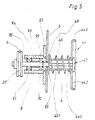
- FIG. 5 shows a modified drive device in which the drive whorl 20 is arranged on one side and the polygonal bolt 4 with the paraffin support plate 44 on the other side of the holder 5 reinforced by an additional plate 51.
- the polygonal bolt 4 which has a support plate 48 for the compression spring 46 at its end facing the holder 5, is seated on a shaft 9 in a rotationally fixed manner.
- the shaft 9 is supported in a bearing bush 92 by means of two roller bearings 90 and 91.
- the roller bearings 90 and 91 are axially secured in the usual manner by spring washers 93, 94 and 95 and a spacer bush 96.
- the bearing bush 92 is pressed into the plate 51.
- the shaft 9 carries the drive whorl 20 with which the drive belt 3 is engaged.
- both the driving strand 30 and the returning strand 31 of the drive belt 3 are located behind the holder 5, so that the drive belt 3 is well protected.
Landscapes
- Chemical & Material Sciences (AREA)
- Oil, Petroleum & Natural Gas (AREA)
- Spinning Or Twisting Of Yarns (AREA)
- Treatments For Attaching Organic Compounds To Fibrous Goods (AREA)
Description
Die vorliegende Erfindung betrifft eine Antriebsvorrichtung für eine Paraffiniereinrichtung einer Textilmaschine, die eine Vielzahl gleichartiger Paraffiniereinrichtungen aufweist, von denen jede einen drehbaren Mehrkantbolzen besitzt, der mit einem Antriebswirtel verbunden ist, mit welchem ein endloser Antriebsriemen in Eingriff steht, wobei der Mehrkantbolzen einen festen Paraffinierkörper aufnimmt, an welchem sich ein zu paraffinierender Faden abstützt.The present invention relates to a drive device for a waxing device of a textile machine, which has a multiplicity of similar waxing devices, each of which has a rotatable polygonal bolt which is connected to a drive whorl with which an endless drive belt is engaged, the polygonal bolt receiving a solid waxing body on which a thread to be waxed is supported.
In der Regel wird der feste Paraffinkörper durch den einer Spulvorrichtung zugeführten Faden in Drehung versetzt (DE-Gm 7611 630). Hierbei besteht jedoch die Gefahr, daß der Faden sich in den Paraffinkörper einschneidet und damit ein gleichmäßiges Abtragen des Paraffins unmöglich macht. Vielfach wird deshalb pro Paraffiniereinrichtung ein individueller Antriebsmotor vorgesehen (DE-OS 2 316 452). Dies jedoch macht einen solchen Antrieb sehr aufwendig.As a rule, the solid paraffin body is rotated by the thread fed to a winding device (DE-Gm 7611 630). Here, however, there is a risk that the thread cuts into the paraffin body and thus makes uniform removal of the paraffin impossible. In many cases, therefore, an individual drive motor is provided per paraffinizing device (DE-OS 2 316 452). However, this makes such a drive very complex.
Es ist auch bekannt geworden, mit Hilfe einer zentralen, sich über eine Vielzahl gleichartiger Paraffiniereinrichtungen erstreckende Welle über aufwendige Zwischengetriebe Einzelantriebe anzutreiben, die dann ihrerseits die einzelnen Paraffiniereinrichtungen antreiben (FR-PS 1 293 729, DE-PS 1 560 460 und DE-OS 2 227 308). Diese Einzelantriebe sind aufwendig. Im Fall eines Reibradgetriebes kommt noch hinzu, daß mit zunehmender Abnutzung der Reibräder die Antriebsübertragung immer unzuverlässiger wird, so daß ein einwandfreies Paraffinieren des Fadens nicht mehr gewährleistet ist.It has also become known to drive individual drives with the aid of a central shaft, which extends over a large number of similar paraffinizing devices, via complex intermediate gears, which in turn then drive the individual paraffinizing devices (FR-PS 1 293 729, DE-PS 1 560 460 and DE-OS 2 227 308). These single drives are complex. In the case of a friction gear, there is also the fact that the drive transmission becomes increasingly unreliable with increasing wear of the friction wheels, so that perfect waxing of the thread is no longer guaranteed.
Aufgabe der Erfindung ist es, für eine Paraffiniereinrichtung eine einfache und sichere Antriebsvorrichtung zu schaffen.The object of the invention is to provide a simple and safe drive device for a paraffinizing device.
Diese Aufgabe wird erfindungsgemäß dadurch gelöst, daß der Antriebsriemen mit einer Vielzahl benachbarter Paraffiniereinrichtungen in Eingriff steht. Ein solcher Antrieb ist äußerst einfach. Darüber hinaus hat sich dieser Antrieb selbst bei den niedrigen Drehzahlen, die für den Paraffinkörper gewünscht werden, als völlig zuverlässig erwiesen, so daß ein gleichmäßiges Paraffinieren des Fadens auch auf lange Zeit gewährleistet ist.This object is achieved in that the drive belt is in engagement with a plurality of adjacent paraffinizing devices. Such a drive is extremely simple. In addition, this drive has proven to be completely reliable even at the low speeds that are desired for the paraffin body, so that a uniform waxing of the thread is guaranteed even over a long period.
Es sind zwar schon gemeinsame Riemenantriebe für eine Vielzahl gleichartiger Elemente einer Textilmaschine bekannt, jedoch nur für schnellaufende Elemente, wie z. B. Spindeln, Spinnrotoren und Auflösewalzen von Offenend-Spinnmaschinen (DE-AS 1 818 034). Bei diesen hohen Geschwindigkeiten kommen kleinere Schwankungen des auf das angetriebene Element einwirkenden Gegenmomentes nicht zur Wirkung, so daß ein gleichförmiger Antrieb gewährleistet ist. Bei niedrigen Drehzahlen dagegen bewirken derartige Schwankungen Drehzahländerungen. Überraschenderweise hat sich jedoch gezeigt, daß trotz dieser evtl. auftretenden Drehzahlschwankungen ein einwandfreies Paraffinieren des Fadens sichergestellt wird.There are already known belt drives for a variety of similar elements of a textile machine, but only for high-speed elements, such as. B. spindles, spinning rotors and opening rollers of open-end spinning machines (DE-AS 1 818 034). At these high speeds, small fluctuations in the counter-torque acting on the driven element do not come into effect, so that a uniform drive is ensured. At low speeds, however, such fluctuations cause speed changes. Surprisingly, however, it has been shown that, despite these possible fluctuations in speed, a perfect waxing of the thread is ensured.
Unter « Antriebsriemen " im Sinne der vorliegenden Erfindung werden nicht nur Flachriemen verstanden, sondern alle langgestreckten Antriebselemente wie Rundschnüre, Keilriemen, Zahnriemen etc. sollen hiermit erfaßt werden."Drive belts " in the sense of the present invention are not only understood to mean flat belts, but all elongate drive elements such as round cords, V-belts, toothed belts, etc. are to be covered herewith.
Um den Antrieb weiter zu optimieren, ohne daß separate Riemenspannelemente benötigt werden, ist in weiterer Ausgestaltung der Erfindung der Antriebsriemen zickzackartig um die Antriebswirtel der benachbarten Paraffiniereinrichtungen herumgeführt. Der diesen Paraffiniereinrichtungen gemeinsam zugeordnete Antriebsriemen steht somit abwechselnd auf der einen und auf der anderen Seite der gemeinsamen Fläche, auf welcher sich die Mehrkantbolzen dieser Paraffiniereinrichtungen befinden, mit den Antriebswirteln dieser Paraffiniereinrichtungen in antriebsmäßiger Verbindung. Die gemeinsame Fläche kann dabei eine Ebene sein oder (bei geneigter Anordnung der Paraffiniereinrichtungen an runden Maschinen) auch eine Konusform aufweisen.In order to further optimize the drive without the need for separate belt tensioning elements, in a further embodiment of the invention the drive belt is zigzagged around the drive whorls of the adjacent paraffinizing devices. The drive belt jointly assigned to these waxing devices is thus alternately on the one and on the other side of the common surface, on which the polygonal bolts of these waxing devices are located, in driving connection with the drive whorls of these waxing devices. The common surface can be a plane or (in the case of an inclined arrangement of the paraffining devices on round machines) also have a conical shape.
Bei einer als Offenend-Spinnmaschine ausgebildeten Textilmaschine, welche eine Vielzahl nebeneinanderliegender Offenend-Spinnvorrichtungen sowie eine Welle zur Steuerung der Faserlieferung in diese Offenend-Spinnvorrichtungen aufweist, steht der Antriebsriemen zweckmäßigerweise mit dieser Welle in antriebsmäßiger Verbindung. Diese Welle zur Steuerung der Faserlieferung wird in Abhängigkeit vom Faserdurchsatz durch die Offenend-Spinnvorrichtungen angetrieben, so daß die Paraffiniereinrichtungen an diesen Durchsatz angepaßt und somit stets nur mit der für diesen Durchsatz erforderlichen Geschwindigkeit angetrieben werden. Hierdurch wird eine sehr hohe Lebensdauer des Antriebs für die Paraffiniereinrichtungen erreicht.In the case of a textile machine designed as an open-end spinning machine, which has a large number of adjacent open-end spinning devices and a shaft for controlling the delivery of fibers into these open-end spinning devices, the drive belt is expediently connected to this shaft in terms of drive. This shaft for controlling the fiber delivery is driven as a function of the fiber throughput by the open-end spinning devices, so that the paraffinizing devices are adapted to this throughput and are therefore always driven only at the speed required for this throughput. As a result, the drive for the paraffinizing devices has a very long service life.
Eine baulich besonders einfache Ausbildung des Erfindungsgegenstandes wird ermöglicht, wenn der Antriebswirtel einer jeden Paraffiniereinrichtung zwischen einer Halterung für diese Paraffiniereinrichtung und dem Paraffinierkörper angeordnet ist. Dies führt auch zu einer besonders guten Zugänglichkeit zu diesem Antrieb. Eine weitere Verringerung des baulichen Aufwandes wird erzielt, wenn der Mehrkantbolzen einteilig mit dem Antriebswirtel ausgebildet ist. Zur Erleichterung der Montage und auch zur Gewichtsersparnis der anzutreibenden Paraffiniereinrichtungen ist zweckmäßigerweise der Mehrkantbolzen als Hohlkörper ausgebildet, welcher die Lagerung und Befestigung aufnimmt. Gemäß einer einfachen konstruktiven Ausgestaltung des Erfindungsgegenstandes weist die Befestigung einen Gewindebolzen auf, welcher in eine in der Halterung vorgesehenen Gewindebuchse eingeschraubt ist. Vorteilhafterweise ist der Hohlraum des Mehrkantbolzens an seinem der Lagerung abgewandten Ende durch eine Kappe verschließbar, die den Außenumfang des Mehrkantbolzens überragt und als Anschlag für einen elastisch beaufschlagten, auf dem Mehrkantbolzen gelagerten Paraffin-Stützteller ausgebildet ist. Vorteilhafterweise besitzt zu diesem Zweck die Kappe Ecken, den Mehrkantbolzen an seinen angefasten Kanten überragen, während die Seitenflächen des Mehrkantbolzens und der Kappe bündig sind, wobei der Paraffin-Stützteller an das Profil des Mehrkantbolzens eng angepaßte Führungsflächen aufweist. Auf diese Weise wird erreicht, daß der Paraffinkörper über den als Anschlag für den Paraffin-Stützteller dienenden Einsatz hinweg auf den Mehrkantbolzen aufgeschoben werden kann, ohne daß hierbei das Spiel zwischen Mehrkantbolzen und Paraffinkörper vergrößert werden muß.A particularly simple construction of the subject matter of the invention is made possible if the drive whorl of each paraffinizing device is arranged between a holder for this paraffinizing device and the paraffinizing body. This also leads to particularly good accessibility to this drive. A further reduction in the structural outlay is achieved if the polygonal bolt is formed in one piece with the drive whorl. In order to facilitate assembly and also to save weight on the paraffinizing devices to be driven, the polygonal bolt is expediently designed as a hollow body which receives the mounting and fastening. According to a simple constructive embodiment of the subject matter of the invention, the fastening has a threaded bolt which is screwed into a threaded bushing provided in the holder. Advantageously, the cavity of the polygonal bolt can be closed at its end facing away from the bearing by a cap which projects beyond the outer circumference of the polygonal bolt and is designed as a stop for an elastically loaded paraffin support plate mounted on the polygonal bolt. advantage For this purpose, the cap has corners, the polygonal bolt protrudes on its chamfered edges, while the side surfaces of the polygonal bolt and the cap are flush, the paraffin support plate having guide surfaces closely matched to the profile of the polygonal bolt. In this way it is achieved that the paraffin body can be pushed over the insert serving as a stop for the paraffin support plate onto the polygonal bolt without the play between the polygonal bolt and the paraffin body having to be increased.
Bei einer Textilmaschine, bei welcher der Antriebsriemen längs den angetriebenen Paraffiniereinrichtungen wieder zur Antriebsstelle zurückgeführt wird, ist vorzugsweise ein Abstützelement für das rücklaufende Trum des Antriebsriemens vorgesehen. Bei einer Maschine, bei welcher die Paraffiniereinrichtung einer Spulvorrichtung vorgeschaltet ist, welcher ihrerseits ein sich von der Halterung bis über den Antriebswirtel erstreckender Fadenspannungsausgleichselement vorgeschaltet ist, ist dieses Abstützelement dabei vorteilhafterweise dicht unterhalb dieses Fadenspannungsausgleichselementes angeordnet, so daß der Antriebsriemen durch diese Abdeckung geschützt wird. Gemäß einer bevorzugten Ausbildung der erfindungsgemäßen Vorrichtung dient das Abstützelement als Träger eines die Vorschubbewegung des Paraffinkörpers begrenzenden Anschlages.In a textile machine in which the drive belt is returned along the driven paraffinizing devices to the drive point, a support element for the returning run of the drive belt is preferably provided. In the case of a machine in which the paraffinizing device is connected upstream of a winding device, which in turn is preceded by a thread tension compensation element that extends from the holder to the drive whorl, this support element is advantageously arranged just below this thread tension compensation element, so that the drive belt is protected by this cover. According to a preferred embodiment of the device according to the invention, the support element serves as a carrier for a stop limiting the advancing movement of the paraffin body.
In weiterer Ausgestaltung einer solchen Ausführung ist beiderseitig vom Paraffinkörper je ein als Abstützelement ausgebildeter Träger angeordnet, wobei sich der Anschlag von einem dieser Träger zu dem anderen Träger erstreckt. Zweckmäßigerweise ist dabei das Abstützelement, das in bezug auf die am Anschlag wirkende Drehbewegung des Paraffinkörpers vor diesem angeordnet ist, als Schwenklager für den Anschlag ausgebildet, während das nach dem Paraffinkörper angeordnete Abstützelement auf seiner der Paraffiniereinrichtung abgewandten Seite einen Längsschlitz zur Aufnahme des Endes des Anschlages aufweist. Bei dieser Anordnung wird sichergestellt, daß trotz einfachster Lagerung des Anschlages dieser durch den rotierenden Paraffinkörper nicht aus dem als Aufnahme dienenden Längsschlitz herausgeschwenkt werden kann. Zum Schutz und Abdecken des rücklaufenden Trums des Antriebsriemens kann für dieses Trum ein auf seiner der Paraffiniervorrichtung zugewandten Seite offener Kanal vorgesehen sein, welcher in vorteilhafter Ausgestaltung des Erfindungsgegenstandes durch die Halterung und eine Abdeckleiste gebildet wird, welche integrierter Bestandteil des Fadenspannungsausgleichselementes ist.In a further embodiment of such an embodiment, a carrier designed as a supporting element is arranged on both sides of the paraffin body, the stop extending from one of these carriers to the other carrier. The support element, which is arranged in front of the paraffin body with respect to the rotational movement acting on the stop, is expediently designed as a pivot bearing for the stop, while the support element arranged after the paraffin body has a longitudinal slot on its side facing away from the waxing device for receiving the end of the stop having. This arrangement ensures that, despite the simplest mounting of the stop, it cannot be pivoted out of the longitudinal slot serving as a receptacle by the rotating paraffin body. To protect and cover the returning run of the drive belt, an open channel can be provided for this run on its side facing the paraffinizing device, which in an advantageous embodiment of the subject matter of the invention is formed by the holder and a cover strip, which is an integral part of the thread tension compensation element.
Um den Paraffinkörper nicht stets mit der höchsten Geschwindigkeit, die nur bei ganz bestimmter Betriebsbedingungen erforderlich ist, laufen lassen zu müssen, ist erfindungsgemäß vorzugsweise vorgesehen, daß die Drehgeschwindigkeit des Paraffinkörpers an die der Offenend-Spinnvorrichtung zugeführte Fasermasse angepaßt wird. Dies geschieht, wie oben bereits erwähnt, vorzugsweise dadurch, daß der Antrieb der Paraffinkörper von der die Lieferwalzen tragenden Welle direkt abgenommen wird, doch ist eine andere - z. B. elektrische - Geschwindigkeitskopplung prinzipiell ebenfalls möglich.In order not to always have to run the paraffin body at the highest speed, which is only required under very specific operating conditions, the invention preferably provides for the rotational speed of the paraffin body to be adapted to the fiber mass fed to the open-end spinning device. This is done, as already mentioned above, preferably in that the drive of the paraffin body is removed directly from the shaft carrying the delivery rollers, but another - e.g. B. electrical - speed coupling also possible in principle.
Die Erfindung schafft eine einfache Vorrichtung, die kompakt ist, wenig Energie für den Antrieb der Paraffinkörper benötigt und die ohne Wartungsaufwand zuverlässig arbeitet. Trotz geringem maschinenbaulichen Aufwandes ist die Vorrichtung langlebig und bedienungsfreundlich.The invention provides a simple device that is compact, requires little energy to drive the paraffin body and that works reliably without maintenance. Despite the low mechanical engineering expenditure, the device is durable and user-friendly.
Die Erfindung wird anhand von Zeichnungen nachstehend näher beschrieben. Es zeigen :
- Fig. 1 eine Offenend-Spinnmaschine mit der erfindungsgemäßen Vorrichtung in der Vorderansicht ;
- Fig. 2 eine erfindungsgemäß angetriebene Paraffiniereinrichtung in perspektivischer Ansicht ;
- Fig. 3 eine bevorzugte Ausbildung der erfindungsgemäß angetriebenen Paraffiniereinrichtung im Querschnitt ;
- Fig. 4 ein Detail aus Fig. 3 in der Vorderansicht ; und
- Fig. 5 eine Abwandlung der erfindungsgemäß angetriebenen Paraffiniereinrichtung im Querschnitt.
- Figure 1 is an open-end spinning machine with the device according to the invention in the front view.
- 2 shows a paraffinizing device driven according to the invention in a perspective view;
- 3 shows a preferred embodiment of the paraffinizing device driven according to the invention in cross section;
- FIG. 4 shows a detail from FIG. 3 in a front view; and
- Fig. 5 shows a modification of the paraffinizing device driven according to the invention in cross section.
Die Erfindung kann bei verschiedenen Textilmaschinen Anwendung finden, auf denen der Faden paraffiniert werden kann. Die Textilmaschinen können dabei eine gestreckte oder auch eine runde Form aufweisen. Außerdem spielt es keine Rolle, ob es sich um garnproduzierende Spinnmaschinen, garnbehandelnde Spulmaschinen oder garnverarbeitende Maschinen (Strick- oder Wirkmaschinen) handelt. Für die nachfolgende Erörterung wurde als Beispiel eine Offenend-Spinnmaschine (Fig. 1) gewänlt, die eine Vielzahl von Spinnstellen 1 und entsprechend auch von Paraffiniereinrichtungen 2 aufweist. Die gezeigte Spinnmaschine weist sieben Spinnstellen 1 auf ; in der Praxis sind dies jedoch erheblich mehr. Die Spinnmaschine selber ist nur schematisch dargestellt, wobei alle für das Verständnis der Erfindung nicht unbedingt erforderlichen Elemente der Übersichtlichkeit halber weggelassen wurden. Die Offenend-Spinnmaschine besitzt an ihren Enden je ein Endgestell 11 und 12. Zwischen den Endgestellen 11 und 12 weist die Spinnmaschine pro Spinnstelle 1 eine durch einen Deckel 10 abgedeckte Spinnvorrichtung auf. Der Spinnvorrichtung wird das Fasermaterial 13, das ihr in einer Spinnkanne 14 vorgelegt wird, mit Hilfe einer Liefervorrichtung zugeführt, die von einer sich über die gesamte Maschinenlänge erstreckenden Welle 19 angetrieben wird.The invention can be used in various textile machines on which the thread can be waxed. The textile machines can have an elongated or a round shape. In addition, it does not matter whether it is yarn-producing spinning machines, yarn-treating winding machines or yarn-processing machines (knitting or warp knitting machines). For the following discussion, an open-end spinning machine (FIG. 1) was chosen as an example, which has a large number of spinning positions 1 and, accordingly, paraffinizing
Der in der Spinnvorrichtung gesponnene Faden 15 wird mit Hilfe von Abzugswalzen 17 und 18 abgezogen und auf eine Spule 16 aufgewickelt, wobei der Faden 15 der Spule 16 in üblicher und deshalb nicht gezeigter Weise changierend vorgelegt wird. Im Fadenlauf zwischen den Abzugswalzen 17 und 18 und der Spule 16 (oder einer Garnverarbeitungsstelle bei garnverarbeitenden Maschinen) ist eine Paraffiniereinrichtung 2 angeordnet.The
Jede Paraffiniereinrichtung 2 besitzt einen Mehrkantbolzen 4 (Fig. 2), auf welchem ein Paraffinkörper 21 zum Paraffinieren des Fadens 15 aufgesteckt wird. Der Mehrkantbolzen 4 steht in antriebsmäßiger Verbindung mit einem Antriebswirtel 20. Die Antriebswirtel 20 der Paraffiniereinrichtungen 2 einer Vielzahl nebeneinanderliegender Spinnstellen 1 werden von einem gemeinsamen Antriebsriemen 3 angetrieben.Each
Prinzipiell kann der Antriebsriemen 3 stets auf ein und derselben Seite an den Antriebswirteln 20 (Fig. 2) der Paraffiniervorrichtungen 2 anliegen, wobei der Antriebsriemen 3 durch übliche, nichtgezeigte Spannrollen gespannt und in Anlage an den Antriebswirteln 20 gehalten wird. Die Paraffinkörper 21 werden auf diese Weise gleichmäßig angetrieben. Selbst wenn aufgrund von Fadenspannungsänderungen sich das vom Faden 15 auf den Paraffinkörper 21 ausgeübte Moment kurzzeitig ändert, so wird dennoch keine so starke Drehgeschwindigkeitsänderung erzielt, die eine einwandfreie Paraffinierung des Fadens 15 beeinträchtigen könnte. Vielmehr hat sich gezeigt, daß die Paraffinierung des Fadens 15 und die Abarbeitung der Paraffinkörper 21 sehr gleichförmig erfolgt.In principle, the
Nachstehend wird anhand der Fig. 1 eine besonders vorteilhafte Ausbildung der Vorrichtung beschrieben, bei welcher der Antriebsriemen 3 die Antriebswirtel 20 (Fig. 2) zickzackartig umschlingt. Wie bei zwei Spinnstellen 1 angedeutet, befinden sich die Achsen der Paraffiniereinrichtungen 2 auf einer gemeinsamen Fläche E, während das antreibende Trum 30 abwechselnd auf der einen und auf der anderen Seite dieser Fläche E mit den Antriebswirteln 20 (Fig. 2) der Paraffiniereinrichtungen 2 in antriebsmäßiger Verbindung steht. Auf diese Weise wird jeder zweite Paraffinkörper 21 im Uhrzeigersinn angetrieben, während die sich dazwischen befindenden Paraffinkörper 21 gegen den Uhrzeigersinn angetrieben werden. Dies spielt jedoch für das Paraffinieren des Fadens 15 keine Rolle, der unabhängig von der Drehrichtung des Paraffinkörpers 21 gleich gut paraffiniert wird.A particularly advantageous embodiment of the device is described below with reference to FIG. 1, in which the
Je nach Art der Maschine handelt es sich bei dieser Fläche E um eine Ebene (bei langgestreckten Maschinen und bei runden Maschinen, in denen sich die Achsen der Paraffiniervorrichtungen 2 genau radial nach außen erstrecken) oder um eine konusförmige Fläche (bei runden Maschinen, in denen die Achsen der Paraffinvorrichtungen 2 geneigt angeordnet sind).Depending on the type of machine, this surface E is a plane (in the case of elongated machines and in the case of round machines in which the axes of the
Durch die Zickzackführung des Antriebsriemens 3 wird dieser gespannt gehalten und umschlingt die Antriebswirtel 20 über einen größeren Bereich als bei üblichen Tangentialantrieben, so daß hiermit bei Wegfall von Spannrollen dennoch eine gute Mitnahme der Antriebswirtel 20 erzielt wird.The zigzag guide of the
Auch der Antrieb des Antriebsriemens 3 kann im Prinzip auf jede beliebige Art und Weise erfolgen. Gemäß Fig. 1 erhält der Antriebsriemen 3 seinen Antrieb von der Welle 19, mit welcher das Fasermaterial 13 der Spinnvorrichtung zugeführt wird. Hierzu ist in Nähe des Endgestelles 11 auf der Welle 19 eine Antriebsrolle 32 angeordnet. Zwischen dieser Antriebsrolle 32 und einer Umlenkrolle 33 für das antreibende Trum 30 zur Umlenkung des Antriebsriemens 3 in Richtung der Maschinenlängsachse befindet sich eine weitere Umlenkrolle 34, mit welcher der Antriebsriemen 3 der Umlenkrolle 33 im optimalen Winkel zugeführt wird. Der Antriebsriemen 3 liegt, wie bereits beschrieben, an den Antriebswirteln 20 der Paraffiniereinrichtungen 2 abwechselnd von oben bzw. von unten an. Am anderen Maschinenende wird der Antriebsriemen 3 durch eine weitere Umlenkrolle 35 in Näne des Endgestelles 12 umgelenkt. Das rücklaufende Trum 31 des Antriebsriemens 3 wird sodann oberhalb der Paraffiniereinrichtungen 2 zu einer Umlenkrolle 36 in Nähe des Endgestelles 11 zurückgeführt, von wo aus der Antriebsriemen 3 wieder zur Antriebsrolle 32 gelangt.In principle, the
Zum Auflegen des Antriebsriemens auf die Antriebswirtel 20 wird wie folgt verfahren : Zunächst wird der Antriebsriemen 3 auf die Antriebsrolle 32 sowie die Umlenkrollen 34, 33, 36 und 35 aufgelegt, ohne daß der Antriebsriemen 3 gleich über die Antriebswirtel 20 geführt wird. Sodann wird der Antriebsriemen 3 abwechselnd über und unter einen mit dem Antriebswirtel 20 verbundenen Mehrkantbolzen 4 (Fig. 3) gelegt. Da der Antriebsriemen 3 hierbei nur geringfügig durch die Zickzacklage um die Mehrkantbolzen 4 der Paraffiniereinrichtungen 2 umgelenkt wird, ist dieser Antriebsriemen 3 nur geringfügig gespannt. Nun wird der Antriebsriemen 3 auf die Antriebswirtel 20 aufgelegt. Dadurch wird der Zickzackverlauf des Antriebsriemens 3 verstärkt, wobei der Antriebsriemen 3 seine Betriebsspannung erhält.The procedure for placing the drive belt on the drive whorls 20 is as follows: First, the
Der Antrieb des Antriebriemens 3 von der Welle 19 der Speisevorrichtung der Offenend-Spinnmaschine aus bewirkt, daß die Paraffinkörper 21 mit einer an den Faserdurchsatz angepaßten Geschwindigkeit angetrieben wird. Wird nämlich den Offenend-Spinnvorrichtungen viel Faserband zugeführt, so daß der Faserdurchsatz hoch ist, so erhöht sich entsprechend auch die Drehgeschwindigkeit der Paraffinkörper 21. Wird den Spinnvorrichtungen weniger Faserband zugeführt, so wird entsprechend auch die Drehgeschwindigkeit der Paraffinkörper 21 abgesenkt, so daß die Paraffinkörper 21 immer nur mit der erforderlichen Drehzahl und nicht schneller angetrieben werden. Dies führt zu einer längeren Lebensdauer des Antriebes der Paraffineinrichtungen 2.The drive of the
Nachstehend wird anhand der Fig. 2 und 3 eine besonders vorteilhafte Ausbildung der Antriebsvorrichtung und der entsprechend ausgebildeten Paraffiniereinrichtung 2 beschrieben. Diese wird hierbei von einer als Halteplatte ausgebildeten Halterung 5 getragen. Hierzu ist in die Halteplatte 5 eine Gewindebuchse 40 eingepreßt oder auf eine andere Weise fest verbunden, in welche ein Gewindebolzen 41 eingeschraubt ist. Auf dem Gewindebolzen 41 sitzen zwei Wälzlager 42 und 43, auf denen der Mehrkantbolzen 4 drehbar gelagert ist. Der Mehrkantbolzen 4 ist als Hohlkörper ausgebildet, was einerseits den Vorteil hat, daß der Gewindebolzen 41 von der Vorderseite des Mehrkantbolzens 4 aus zugänglich ist, und andererseits das Gewicht der Paraffiniereinrichtung 2 reduziert und damit zu einer Erhöhung ihrer Lebensdauer beiträgt.A particularly advantageous embodiment of the drive device and the correspondingly configured
Der Mehrkantbolzen 4 weist ein Mehrkantprofil 400 auf, auf welchem ein Paraffin-Stützteller 44 mit einem Führungsabschnitt 440, welches eine an das Mehrkantprofil 400 angepaßte Führungsfläche 441 aufweist, verschiebbar gelagert ist. An dem dem Antriebswirtel 20 abgewandten Ende dieses Führungsabschnittes 440 geht der Paraffin-Stützteller 44 in eine radiale Stützfläche 442 über, die durch einen Ringbund 443 begrenzt ist, welcher diese Stützfläche 442 auf ihrer dem Antriebswirtel 20 abgewandten Seite axial überragt.The polygonal bolt 4 has a
Der Antriebswirtel 20 ist lediglich mit einer radialen Verbindungsfläche 200 mit dem Mehrkantbolzen 4 verbunden, so daß sich zwischen dem Antriebswirtel 20 und dem Mehrkantbolzen 4 eine ringförmige Ausnehmung 45 zur Aufnahme einer Druckfeder 46 bildet. Durch diese Druckfeder 46, die sich an der radialen Verbindungsfläche 200 einerseits und an der radialen Stützfläche 442 andererseits abstützt, wird der Paraffin-Stützteller 44 in Richtung zum freien Ende des Mehrkantbolzens 4 beaufschlagt und sorgt auf diese Weise dafür, daß der Paraffinkörper 21 stets in vorgegebenem Maße in die Fadenlaufebene hineinragt, so daß er in gewünschter Weise an dem Faden 15 anliegt. Der Paraffinkörper 21 wird dabei durch einen Anschlag 6, der später noch näher beschrieben wird, in dieser Position gegen die Wirkung der Druckfeder 46 gehalten.The
Wie zuvor erwähnt, ist der Mehrkantbolzen 4 als Hohlkörper ausgebildet. In das dem Antriebswirtel 20 abgewandte offene Ende des Mehrkantbolzens 4 ragt ein zylinderförmiger Ansatz 470 einer Kappe 47 hinein. Dieser zylinderförmige Ansatz 470 dient der Befestigung der Kappe 47 im Mehrkantbolzen 4. Dies kann durch zusammenarbeitende Rasten oder durch eine entsprechend enge Passung zwischen diesen Teilen geschehen.As mentioned above, the polygonal bolt 4 is designed as a hollow body. A
Die Kappe 47 weist ferner eine Anschlagfläche 471 auf, mit welcher er an der Stirnseite des Mehrkantbolzens 4 anliegt. Wie Fig. 4 zeigt, sind die Seitenflächen 472 der Kappe mit den Seitenflächen des Mehrkantbolzens 4 bündig. Die Kanten des Mehrkantbolzens 4 sind im Gegensatz zu den Kanten der Anschlagfläche 471 der Kappe 47 mit Anfasungen 401 versehen. Auf diese Weise überragen die Ecken 473 diese Anfasungen 401. Wie zuvor erwähnt, ist die Führungsfläche 441 des Paraffin-Stütztellers 44 an das Mehrkantprofil 400 des Mehrkantbolzens 4 angepaßt, besitzt somit ebenfalls den Anfasungen 401 des Mehrkantbolzens 4 entsprechende Flächen.The
Die Ecken 473 der Kappe 47 bilden somit einen Anschlag für den Paraffin-Stützteller 44 und halten diesen sicher auf dem Mehrkantbolzen 4.The
Da die Seitenflächen 472 der Kappe 47 bündig mit den Seitenflächen des Mehrkantbolzens 4 abschließen, behindert die Kappe 47 das Aufschieben eines Paraffinkörpers 21 auf den Mehrkantbolzen 4 in keinster Weise und beeinträchtigt ebensowenig seine Verschiebung auf dem Mehrkantbolzen 4.Since the side surfaces 472 of the
Die Kappe 47 besitzt eine zentrische Bohrung 474, welche, ohne daß die Kappe 47 aus dem Mehrkantbolzen 4 herausgenommen werden muß, den Zugang zum Gewindebolzen 41 ermöglicht. Dies erleichtert einen raschen Ausbau der Paraffiniereinrichtung 2, sollte dieser einmal nötig werden.The
Bei der zuvor im Aufbau beschriebenen Vorrichtung befindet sich der Antriebswirtel 20 der Paraffiniereinrichtung 2 zwischen der Halterung 5 für die Paraffiniereinrichtung 2 und dem Paraffinkörper 21. Wie später anhand der Fig. 5 noch beschrieben werden wird, ist dies jedoch nicht Voraussetzung.In the device described above in the construction, the
Im gezeigten Ausführungsbeispiel wird der Antriebsriemen 3 längs den angetriebenen Paraffiniereinrichtungen 2 wieder zur Antriebsstelle (Welle 19, siehe Fig. 1) zurückgeführt. Dabei wird der Antriebsriemen 3 so gespannt gehalten, daß die beiden Trums 30 und 31 einander nicht berühren. Um dies auch bei langen Maschinen, bei denen mit diesem Antriebsriemen 3 eine große Anzahl von Paraffiniereinrichtungen 2 angetrieben wird, sicherzustellen, sind gemäß den Fig. 2 und 3 Abstützelemente 60 und 61 für das außer Eingriff mit den Paraffiniereinrichtungen 2 stehende rücklaufende Trum 31 des Antriebsriemens 3 vorgesehen. Prinzipiell genügt es, wenn pro Paraffiniereinrichtung 2 lediglich ein Abstützelement 60 oder 61 vorgesehen ist, wobei es nicht einmal erforderlich ist, daß jede Paraffiniereinrichtung 2 ein solches Abstützelement 60 bzw. 61 besitzt.In the exemplary embodiment shown, the
Gemäß Fig. 2 ist das Abstützelement 60 als Träger des die Vorschubbewegung des Paraffinkörpers 21 begrenzenden Anschlages 6 ausgebildet. Auch hierfür genügt pro Paraffiniereinrichtung 2 ein einziges derartiges Abstützelement 60. Da sich jedoch gezeigt hat, daß ein besonders gleichmäßiges Abarbeiten des Paraffinkörpers 21 erzielt wird, wenn sich der Anschlag 6 quer zum Fadenlauf erstreckt, ist gemäß Fig. 2 beidseitig vom Paraffinkörper 21 je ein solcher, als Träger für den Anschlag 6 ausgebildetes Abstützelement 60 und 61 vorgesehen. Der Anschlag 6 erstreckt sich dabei von einem Abstützelement.60 zum anderen Abstützelement 61 eines solchen Abstützelement-Paares.2, the
Prinzipiell kann der Anschlag 6 mit beiden Abstützelementen 60 und 61 starr verbunden sein. Im gezeigten Ausführungsbeispiel ist jedoch nur für das Abstützelement 60 eine Klemmschraube 62 vorgesehen. Das Abstützelement 61 dagegen weist auf seiner oberen Seite - d. h. auf seiner dem Mehrkantbolzen 4 der Paraffiniereinrichtung 2 abgewandten Seite - einen Längsschlitz 610 zur Aufnahme des anderen Endes des Anschlages 6 auf. Nach Lösen der Klemmschraube 62 kann somit der schienenförmige Anschlag 6 in dem ein Schwenklager bildenden Abstützelement 61 in die und aus der Betriebsposition geschwenkt werden, so daß der Austausch des Paraffinkörpers 21 und das anschließende Sichern desselben auf dem Mehrkantbolzen 4 in einfachster und raschester Weise bewerkstelligt werden kann.In principle, the stop 6 can be rigidly connected to both
In den in den Fig. 1 und 2 gezeigten Ausführungsbeispiel wird der zu paraffinierende Faden 15 von unten nach oben bewegt (siehe Pfeil B in Fig. 3). Auf der Fadenablaufseite des Paraffinkörpers 21 befindet sich der Anschlag 6. Bei der vorgegebenen Bewegungsrichtung des Antriebsriemens 3 (siehe Pfeil P) dreht sich der Paraffinkörper 21 in Richtung des Pfeils D gegen den Uhrzeigersinn. Die am Anschlag 6 wirkende Drehbewegung verläuft somit von rechts nach links. In bezug auf diese Drehbewegung ist vor diesem Paraffinkörper das Abstützelement 60 angeordnet, das als Schwenklager für den Anschlag 6 ausgebildet ist. Das den Längsschlitz 610 aufweisende Abstützelement 61 ist entsprechend nach der Paraffiniereinrichtung 2 angeordnet. Auf diese Weise bewirkt der rotierende Paraffinkörper 21, daß der Anschlag 6 in den Längsschlitz 610 hineingedrückt wird, und sichert den Anschlag 6 somit in seiner Betriebsstellung. Der Grund hierfür liegt darin, daß auf den Anschlag 6 zwar zwei einander entgegengerichtete Momente M und m einwirken, von denen allerdings das den größeren Momentenarm (bezogen auf das Abstützelement 60) aufweisende Moment M gegenüber dem den kleineren Momentenarm aufweisende Moment m überwiegt.In the embodiment shown in FIGS. 1 and 2, the
Da die Paraffinkörper 21 abwechselnd im und gegen den Uhrzeigersinn angetrieben werden bei dem geschilderten Antriebsriemen-Verlauf, werden auch die als Schwenklager ausgebildeten Abstützelemente 60 und die den Längsschlitz 610 aufweisenden Abstützelemente 61 jeder zweiten Paraffiniereinrichtung 2 in der abgebildeten Anordnung und die dazwischen befindlichen Paraffiniereinrichtungen 2 in seitenverkehrter Anordnung vorgesehen.Since the
Oberhalb der Abstützelemente 60 und 61 befindet sich bei der gezeigten Offenend-Spinnmaschine ein Fadenspannungsausgleichselement 7. Dieses Element überragt teilweise die Paraffiniereinrichtungen 2. Um den Antriebsriemen 3 zu schützen, ist gemäß den Fig. 2 und 3 die gegenseitige Anordnung von Fadenspannungsausgleichselement 7 und Abstützelementen 60 und 61 so getroffen, daß sich diese Abstützelemente 60 und 61 für das außer Eingriff mit der Paraffiniereinrichtung 2 stehende rücklaufende Trum 31 des Antriebselementes 3 dicht unterhalb des Fadenspannungsausgleichselementes 7 befindet.A thread
In der gezeigten Ausführung wird das rücklaufende Trum 31 des Antriebsriemens 3 in einem Kanal 8 geführt, der auf seiner der Paraffiniereinrichtung 2 zugewandten Seite offen ist. Dieser Kanal 8, der prinzipiell verschieden ausgebildet sein kann, wird gemäß der in den Fig. 2 und 3 gezeigten Ausführung aus der als Halteplatte ausgebildeten Halterung 5, einem abgewinkelten Abschnitt 50 hiervon und einer Abdeckleiste 70 gebildet. Die Abdeckleiste 70 ist integrierter Bestandteil eines Bleches, von welchem ein weiterer Abschnitt das erwähnte Fadenspannungsausgleichselement 7 bildet.In the embodiment shown, the returning
Wie ein Vergleich der Fig. 2 und 3 zeigt, muß der Antriebsriemen 3 nicht unbedingt eine flache Form aufweisen, sondern kann auch eine andere, z. B. runde Form besitzen. Aber auch die Anordnung des Antriebswirtels 20 zwischen der Halterung (Halteplatte 5) und dem Mehrkantbolzen 4 mit dem Paraffinierkörper 21 ist für die Antriebsvorrichtung keine Voraussetzung.As a comparison of FIGS. 2 and 3 shows, the
Fig. 5 zeigt eine abgewandelte Antriebsvorrichtung, bei welcher der Antriebswirtel 20 auf der einen und der Mehrkantbolzen 4 mit dem Paraffin-Stützteller 44 auf der anderen Seite der durch eine zusätzliche Platte 51 verstärkten Halterung 5 angeordnet ist. Der Mehrkantbolzen 4, welcher an seinem der Halterung 5 zugewandten Ende einen Abstützteller 48 für die Druckfeder 46 aufweist, sitzt hierbei drehfest auf einer Welle 9. Die Welle 9 ist mit Hilfe von zwei Wälzlagern 90 und 91 in einer Lagerbuchse 92 gelagert. Die Wälzlager 90 und 91 sind in üblicher Weise durch Federringe 93, 94 und 95 sowie eine Distanzbuchse 96 axial gesichert. Die Lagerbuchse 92 ist in die Platte 51 eingepreßt. An dem dem Mehrkantbolzen 4 abgewandten Ende trägt die Welle 9 den Antriebswirtel 20, mit welchem der Antriebsriemen 3 in Eingriff steht.FIG. 5 shows a modified drive device in which the
Bei einer solchen Ausführung befinden sich - von der Bedienungsseite der Maschine aus gesehen - sowohl das antreibende Trum 30 als auch das rücklaufende Trum 31 des Antriebsriemens 3 hinter der Halterung 5, so daß der Antriebsriemen 3 gut geschützt ist.In such an embodiment, as seen from the operating side of the machine, both the driving
Claims (17)
Applications Claiming Priority (2)
| Application Number | Priority Date | Filing Date | Title |
|---|---|---|---|
| DE3422814 | 1984-06-20 | ||
| DE19843422814 DE3422814A1 (en) | 1984-06-20 | 1984-06-20 | DRIVING DEVICE FOR A PARAFFINING DEVICE |
Publications (3)
| Publication Number | Publication Date |
|---|---|
| EP0165444A2 EP0165444A2 (en) | 1985-12-27 |
| EP0165444A3 EP0165444A3 (en) | 1987-04-29 |
| EP0165444B1 true EP0165444B1 (en) | 1989-04-05 |
Family
ID=6238776
Family Applications (1)
| Application Number | Title | Priority Date | Filing Date |
|---|---|---|---|
| EP85105735A Expired EP0165444B1 (en) | 1984-06-20 | 1985-05-10 | Drive for a waxing device and method for driving such a device |
Country Status (5)
| Country | Link |
|---|---|
| US (1) | US4662166A (en) |
| EP (1) | EP0165444B1 (en) |
| DE (2) | DE3422814A1 (en) |
| HK (1) | HK40193A (en) |
| SG (1) | SG86791G (en) |
Families Citing this family (8)
| Publication number | Priority date | Publication date | Assignee | Title |
|---|---|---|---|---|
| DE3639603C2 (en) * | 1986-11-20 | 1996-08-29 | Schlafhorst & Co W | Waxing device |
| DE4338453C2 (en) * | 1993-11-11 | 1996-01-18 | Rieter Ingolstadt Spinnerei | Waxing device |
| DE4434566C2 (en) * | 1994-09-28 | 2002-07-18 | Rieter Ingolstadt Spinnerei | waxing |
| US5666782A (en) * | 1995-01-31 | 1997-09-16 | Johnson & Johnson Consumer Products, Inc. | Fixture for assembling dental floss dispenser products |
| DE10354588B4 (en) * | 2003-11-21 | 2014-02-20 | Saurer Germany Gmbh & Co. Kg | Paraffining device for a cheese-producing textile machine |
| DE102005028751A1 (en) * | 2005-06-22 | 2007-01-04 | Saurer Gmbh & Co. Kg | Paraffin application assembly for textile thread cross-winder has rotating tip on fixed shaft |
| DE102007018650A1 (en) * | 2007-04-21 | 2008-10-23 | Oerlikon Textile Gmbh & Co. Kg | Paraffining device for a workstation of a cheese-producing textile machine |
| DE102014113346A1 (en) * | 2014-09-16 | 2016-03-17 | Maschinenfabrik Rieter Ag | Apparatus and method for spinning knitting |
Family Cites Families (18)
| Publication number | Priority date | Publication date | Assignee | Title |
|---|---|---|---|---|
| US1799896A (en) * | 1930-07-30 | 1931-04-07 | Graveline Joseph | Spinning frame and spindle-drive mechanism |
| FR758989A (en) * | 1933-07-29 | 1934-01-26 | Ryo Catteau Ets | Rotary pot mill |
| US2400325A (en) * | 1944-01-11 | 1946-05-14 | Farrel Birmingham Co Inc | Thread finishing machine |
| CH378750A (en) * | 1960-07-07 | 1964-06-15 | Schweiter Ag Maschf | Paraffinizing device for winding machines |
| FR1293729A (en) * | 1961-05-19 | 1962-05-18 | Leesona Corp | Device for waxing a moving wire on a winder |
| DE1856450U (en) * | 1961-11-09 | 1962-08-09 | Barmag Barmer Maschf | DOUBLE WIRE TWISTING MACHINE. |
| CH422610A (en) * | 1965-03-19 | 1966-10-15 | Schweiter Ag Maschf | Paraffinizing device on the winding machine |
| US3479988A (en) * | 1967-06-26 | 1969-11-25 | Barber Colman Co | Running thread waxer |
| CH485876A (en) * | 1968-01-22 | 1970-02-15 | Elitex Zavody Textilniho | Machine for ringless, continuous fine spinning of yarn |
| CH499638A (en) * | 1968-11-15 | 1970-11-30 | Vyzk Ustav Bavlnarsky | Device for preparing yarns on spindleless fine spinning machines |
| US3690576A (en) * | 1971-05-03 | 1972-09-12 | Northrop Carolina Inc | Textile thread winder with tension compensating device |
| DE2123231B2 (en) * | 1971-05-11 | 1977-01-13 | Wilhelm Stahlecker Gmbh, 7341 Reichenbach | OPEN-END ROTOR SPINNING MACHINE WITH MULTIPLE SPINNING UNITS |
| ES403310A1 (en) * | 1971-06-08 | 1975-05-01 | Savio Spa | Procedure for the continuous finishing with the perfected double torque retorcing corresponder. (Machine-translation by Google Translate, not legally binding) |
| DE2241727A1 (en) * | 1972-07-07 | 1974-01-24 | Schweiter Ag Maschf | PARAFFINING DEVICE ON WINDING MACHINES |
| IT1037277B (en) * | 1975-04-14 | 1979-11-10 | Nuova S Giorgio Spa | DEVICE FOR PARAFFINING THE YARN |
| DE7927734U1 (en) * | 1979-09-29 | 1980-01-03 | Schubert & Salzer Maschinenfabrik Ag, 8070 Ingolstadt | Device for paraffining yarn |
| IT8183444A0 (en) * | 1981-07-30 | 1981-07-30 | Savio Spa | WAXING DEVICE FOR DOUBLE TWIST TWISTERS. |
| DE3228642C2 (en) * | 1982-07-31 | 1985-02-21 | Schubert & Salzer Maschinenfabrik Ag, 8070 Ingolstadt | Device for paraffining a thread on spinning or winding machines with the aid of a solid paraffin body |
-
1984
- 1984-06-20 DE DE19843422814 patent/DE3422814A1/en not_active Withdrawn
-
1985
- 1985-05-10 EP EP85105735A patent/EP0165444B1/en not_active Expired
- 1985-05-10 DE DE8585105735T patent/DE3569228D1/en not_active Expired
- 1985-06-20 US US06/746,959 patent/US4662166A/en not_active Expired - Fee Related
-
1991
- 1991-10-16 SG SG867/91A patent/SG86791G/en unknown
-
1993
- 1993-04-22 HK HK401/93A patent/HK40193A/en unknown
Also Published As
| Publication number | Publication date |
|---|---|
| HK40193A (en) | 1993-04-30 |
| DE3422814A1 (en) | 1986-01-02 |
| US4662166A (en) | 1987-05-05 |
| DE3569228D1 (en) | 1989-05-11 |
| EP0165444A3 (en) | 1987-04-29 |
| EP0165444A2 (en) | 1985-12-27 |
| SG86791G (en) | 1992-02-14 |
Similar Documents
| Publication | Publication Date | Title |
|---|---|---|
| EP2122022B1 (en) | Ring spinning machines with device for supplying flames | |
| EP2562113B1 (en) | Textile machine with a large number of work positions | |
| EP0165428A2 (en) | Textile machine with several winding units, whereby a yarn is wound on a conical spool at a constant speed | |
| EP0165444B1 (en) | Drive for a waxing device and method for driving such a device | |
| DE4338453C2 (en) | Waxing device | |
| EP0725850B2 (en) | Yarn feeding device for textile machines | |
| EP1006223B1 (en) | Device for opening a sliver | |
| EP3214029B1 (en) | Yarn traversing device for a winding device in a textile machine producing crosswound bobbins | |
| DE3209363C2 (en) | Two-for-one twisting machine | |
| EP3146098A1 (en) | Spinning machine having a false twist device | |
| CH648874A5 (en) | DEVICE FOR PRODUCING EFFECT YARN. | |
| EP0365856B1 (en) | Crossband arrangement at the exit of a carding machine | |
| EP1975288B1 (en) | Spinning machine | |
| DE1685911C3 (en) | Device on spinning or twisting machines for tensioning a stretchable continuous thread | |
| EP1708946B1 (en) | Thread transversing device for a winding device of a cross-wound bobbin producing textile machine | |
| EP1948855B1 (en) | Ring spinning frame comprising drawing systems | |
| CH680801A5 (en) | ||
| DE2855606C2 (en) | Thread guide on a creel for warping and warping systems or the like. | |
| DE2506058A1 (en) | FIBER TAPE RELEASE DEVICE FOR AN OPEN-END SPINNING DEVICE | |
| DE102020118327A1 (en) | Method and device for false twist introduction and spinning machine | |
| DE29700099U1 (en) | Thread head with rotor for a cabling machine | |
| EP2784196B1 (en) | Sample warper | |
| DE2145187A1 (en) | ||
| DE8418609U1 (en) | Drive device for a waxing device | |
| DE69031235T2 (en) | Device for transmitting a rotary movement to a spindle group of a ring spinning machine |
Legal Events
| Date | Code | Title | Description |
|---|---|---|---|
| PUAI | Public reference made under article 153(3) epc to a published international application that has entered the european phase |
Free format text: ORIGINAL CODE: 0009012 |
|
| AK | Designated contracting states |
Designated state(s): CH DE FR GB IT LI |
|
| PUAL | Search report despatched |
Free format text: ORIGINAL CODE: 0009013 |
|
| AK | Designated contracting states |
Kind code of ref document: A3 Designated state(s): CH DE FR GB IT LI |
|
| 17P | Request for examination filed |
Effective date: 19870324 |
|
| ITCL | It: translation for ep claims filed |
Representative=s name: ZINI MARANESI |
|
| EL | Fr: translation of claims filed | ||
| 17Q | First examination report despatched |
Effective date: 19871202 |
|
| ITF | It: translation for a ep patent filed | ||
| GRAA | (expected) grant |
Free format text: ORIGINAL CODE: 0009210 |
|
| AK | Designated contracting states |
Kind code of ref document: B1 Designated state(s): CH DE FR GB IT LI |
|
| GBT | Gb: translation of ep patent filed (gb section 77(6)(a)/1977) | ||
| REF | Corresponds to: |
Ref document number: 3569228 Country of ref document: DE Date of ref document: 19890511 |
|
| ET | Fr: translation filed | ||
| RIN2 | Information on inventor provided after grant (corrected) |
Free format text: OEXLER, RUDOLF * HACKENBERG, WILLI |
|
| PLBE | No opposition filed within time limit |
Free format text: ORIGINAL CODE: 0009261 |
|
| STAA | Information on the status of an ep patent application or granted ep patent |
Free format text: STATUS: NO OPPOSITION FILED WITHIN TIME LIMIT |
|
| 26N | No opposition filed | ||
| ITTA | It: last paid annual fee | ||
| PGFP | Annual fee paid to national office [announced via postgrant information from national office to epo] |
Ref country code: GB Payment date: 19920423 Year of fee payment: 8 |
|
| PGFP | Annual fee paid to national office [announced via postgrant information from national office to epo] |
Ref country code: FR Payment date: 19920428 Year of fee payment: 8 |
|
| PGFP | Annual fee paid to national office [announced via postgrant information from national office to epo] |
Ref country code: CH Payment date: 19920619 Year of fee payment: 8 |
|
| PGFP | Annual fee paid to national office [announced via postgrant information from national office to epo] |
Ref country code: DE Payment date: 19930309 Year of fee payment: 9 |
|
| PG25 | Lapsed in a contracting state [announced via postgrant information from national office to epo] |
Ref country code: GB Effective date: 19930510 |
|
| PG25 | Lapsed in a contracting state [announced via postgrant information from national office to epo] |
Ref country code: LI Effective date: 19930531 Ref country code: CH Effective date: 19930531 |
|
| GBPC | Gb: european patent ceased through non-payment of renewal fee |
Effective date: 19930510 |
|
| PG25 | Lapsed in a contracting state [announced via postgrant information from national office to epo] |
Ref country code: FR Effective date: 19940131 |
|
| REG | Reference to a national code |
Ref country code: CH Ref legal event code: PL |
|
| REG | Reference to a national code |
Ref country code: FR Ref legal event code: ST |
|
| PG25 | Lapsed in a contracting state [announced via postgrant information from national office to epo] |
Ref country code: DE Effective date: 19950201 |