EP2624068B1 - Entwicklerzufuhrbehälter und entwicklerzufuhrsystem - Google Patents
Entwicklerzufuhrbehälter und entwicklerzufuhrsystem Download PDFInfo
- Publication number
- EP2624068B1 EP2624068B1 EP11829425.5A EP11829425A EP2624068B1 EP 2624068 B1 EP2624068 B1 EP 2624068B1 EP 11829425 A EP11829425 A EP 11829425A EP 2624068 B1 EP2624068 B1 EP 2624068B1
- Authority
- EP
- European Patent Office
- Prior art keywords
- developer
- supply container
- developer supply
- pump
- pump portion
- Prior art date
- Legal status (The legal status is an assumption and is not a legal conclusion. Google has not performed a legal analysis and makes no representation as to the accuracy of the status listed.)
- Active
Links
- 238000007599 discharging Methods 0.000 claims description 287
- 230000007246 mechanism Effects 0.000 claims description 143
- 230000003247 decreasing effect Effects 0.000 claims description 15
- 230000036961 partial effect Effects 0.000 claims description 14
- 230000000977 initiatory effect Effects 0.000 claims 1
- 230000001105 regulatory effect Effects 0.000 description 216
- 239000003570 air Substances 0.000 description 118
- 230000000694 effects Effects 0.000 description 80
- 230000006870 function Effects 0.000 description 77
- 230000008859 change Effects 0.000 description 69
- 238000002474 experimental method Methods 0.000 description 50
- 125000004122 cyclic group Chemical group 0.000 description 49
- 230000033228 biological regulation Effects 0.000 description 47
- 230000033001 locomotion Effects 0.000 description 46
- 238000004891 communication Methods 0.000 description 45
- 238000006243 chemical reaction Methods 0.000 description 39
- 230000008602 contraction Effects 0.000 description 34
- 239000000463 material Substances 0.000 description 33
- 238000007789 sealing Methods 0.000 description 30
- 230000007423 decrease Effects 0.000 description 29
- 230000002829 reductive effect Effects 0.000 description 26
- 238000012795 verification Methods 0.000 description 24
- 238000005192 partition Methods 0.000 description 23
- 238000000034 method Methods 0.000 description 22
- 239000000843 powder Substances 0.000 description 21
- 238000003756 stirring Methods 0.000 description 21
- 238000000638 solvent extraction Methods 0.000 description 16
- 230000008878 coupling Effects 0.000 description 15
- 238000010168 coupling process Methods 0.000 description 15
- 238000005859 coupling reaction Methods 0.000 description 15
- 230000009467 reduction Effects 0.000 description 15
- 230000006835 compression Effects 0.000 description 13
- 238000007906 compression Methods 0.000 description 13
- 238000011109 contamination Methods 0.000 description 13
- 239000002245 particle Substances 0.000 description 13
- 230000007774 longterm Effects 0.000 description 12
- 230000008569 process Effects 0.000 description 10
- 238000005086 pumping Methods 0.000 description 10
- 238000006073 displacement reaction Methods 0.000 description 8
- 239000012530 fluid Substances 0.000 description 8
- 230000002093 peripheral effect Effects 0.000 description 8
- 238000003466 welding Methods 0.000 description 8
- 230000005540 biological transmission Effects 0.000 description 7
- 229920001971 elastomer Polymers 0.000 description 7
- 238000005259 measurement Methods 0.000 description 7
- 229920005989 resin Polymers 0.000 description 7
- 239000011347 resin Substances 0.000 description 7
- KAKZBPTYRLMSJV-UHFFFAOYSA-N Butadiene Chemical compound C=CC=C KAKZBPTYRLMSJV-UHFFFAOYSA-N 0.000 description 6
- PPBRXRYQALVLMV-UHFFFAOYSA-N Styrene Chemical compound C=CC1=CC=CC=C1 PPBRXRYQALVLMV-UHFFFAOYSA-N 0.000 description 6
- -1 polypropylene Polymers 0.000 description 6
- 238000011144 upstream manufacturing Methods 0.000 description 6
- 230000000052 comparative effect Effects 0.000 description 5
- 238000010586 diagram Methods 0.000 description 5
- 230000005484 gravity Effects 0.000 description 5
- 238000003780 insertion Methods 0.000 description 5
- 230000037431 insertion Effects 0.000 description 5
- 230000000670 limiting effect Effects 0.000 description 5
- 230000001603 reducing effect Effects 0.000 description 5
- 239000004743 Polypropylene Substances 0.000 description 4
- 230000004308 accommodation Effects 0.000 description 4
- 230000008901 benefit Effects 0.000 description 4
- 230000010354 integration Effects 0.000 description 4
- 238000004519 manufacturing process Methods 0.000 description 4
- 238000000926 separation method Methods 0.000 description 4
- NLHHRLWOUZZQLW-UHFFFAOYSA-N Acrylonitrile Chemical compound C=CC#N NLHHRLWOUZZQLW-UHFFFAOYSA-N 0.000 description 3
- 239000004698 Polyethylene Substances 0.000 description 3
- 230000009471 action Effects 0.000 description 3
- 229920006026 co-polymeric resin Polymers 0.000 description 3
- 239000011362 coarse particle Substances 0.000 description 3
- 238000000151 deposition Methods 0.000 description 3
- 238000005243 fluidization Methods 0.000 description 3
- 230000003287 optical effect Effects 0.000 description 3
- 229920000728 polyester Polymers 0.000 description 3
- 229920000573 polyethylene Polymers 0.000 description 3
- 229920001155 polypropylene Polymers 0.000 description 3
- 238000003860 storage Methods 0.000 description 3
- 239000004793 Polystyrene Substances 0.000 description 2
- 238000000071 blow moulding Methods 0.000 description 2
- 238000004364 calculation method Methods 0.000 description 2
- 230000006837 decompression Effects 0.000 description 2
- 230000008021 deposition Effects 0.000 description 2
- 230000005489 elastic deformation Effects 0.000 description 2
- 238000005265 energy consumption Methods 0.000 description 2
- 230000006872 improvement Effects 0.000 description 2
- 238000001746 injection moulding Methods 0.000 description 2
- 239000002184 metal Substances 0.000 description 2
- 238000012856 packing Methods 0.000 description 2
- 229920002223 polystyrene Polymers 0.000 description 2
- 230000002265 prevention Effects 0.000 description 2
- 230000000717 retained effect Effects 0.000 description 2
- 230000002441 reversible effect Effects 0.000 description 2
- 239000003566 sealing material Substances 0.000 description 2
- 239000000243 solution Substances 0.000 description 2
- 238000012546 transfer Methods 0.000 description 2
- 238000013022 venting Methods 0.000 description 2
- 229920005830 Polyurethane Foam Polymers 0.000 description 1
- 230000001154 acute effect Effects 0.000 description 1
- 239000000853 adhesive Substances 0.000 description 1
- 230000001070 adhesive effect Effects 0.000 description 1
- 239000002390 adhesive tape Substances 0.000 description 1
- 230000002411 adverse Effects 0.000 description 1
- 238000005054 agglomeration Methods 0.000 description 1
- 230000002776 aggregation Effects 0.000 description 1
- 239000012080 ambient air Substances 0.000 description 1
- 238000011001 backwashing Methods 0.000 description 1
- 230000015572 biosynthetic process Effects 0.000 description 1
- 238000004140 cleaning Methods 0.000 description 1
- 230000007547 defect Effects 0.000 description 1
- 238000001514 detection method Methods 0.000 description 1
- 230000006866 deterioration Effects 0.000 description 1
- 238000011038 discontinuous diafiltration by volume reduction Methods 0.000 description 1
- 239000013013 elastic material Substances 0.000 description 1
- 238000005516 engineering process Methods 0.000 description 1
- 230000001747 exhibiting effect Effects 0.000 description 1
- 238000012840 feeding operation Methods 0.000 description 1
- 239000010419 fine particle Substances 0.000 description 1
- 239000011521 glass Substances 0.000 description 1
- 230000002452 interceptive effect Effects 0.000 description 1
- 238000011835 investigation Methods 0.000 description 1
- 239000002655 kraft paper Substances 0.000 description 1
- 239000004973 liquid crystal related substance Substances 0.000 description 1
- 238000012423 maintenance Methods 0.000 description 1
- 239000000203 mixture Substances 0.000 description 1
- 239000000123 paper Substances 0.000 description 1
- 229920005990 polystyrene resin Polymers 0.000 description 1
- 239000011496 polyurethane foam Substances 0.000 description 1
- 230000002035 prolonged effect Effects 0.000 description 1
- 230000001846 repelling effect Effects 0.000 description 1
- 230000004044 response Effects 0.000 description 1
- 230000006641 stabilisation Effects 0.000 description 1
- 238000011105 stabilization Methods 0.000 description 1
- 229910001220 stainless steel Inorganic materials 0.000 description 1
- 239000010935 stainless steel Substances 0.000 description 1
- 230000003068 static effect Effects 0.000 description 1
- 230000001360 synchronised effect Effects 0.000 description 1
Images


Classifications
-
- G—PHYSICS
- G03—PHOTOGRAPHY; CINEMATOGRAPHY; ANALOGOUS TECHNIQUES USING WAVES OTHER THAN OPTICAL WAVES; ELECTROGRAPHY; HOLOGRAPHY
- G03G—ELECTROGRAPHY; ELECTROPHOTOGRAPHY; MAGNETOGRAPHY
- G03G15/00—Apparatus for electrographic processes using a charge pattern
- G03G15/06—Apparatus for electrographic processes using a charge pattern for developing
- G03G15/08—Apparatus for electrographic processes using a charge pattern for developing using a solid developer, e.g. powder developer
-
- G—PHYSICS
- G03—PHOTOGRAPHY; CINEMATOGRAPHY; ANALOGOUS TECHNIQUES USING WAVES OTHER THAN OPTICAL WAVES; ELECTROGRAPHY; HOLOGRAPHY
- G03G—ELECTROGRAPHY; ELECTROPHOTOGRAPHY; MAGNETOGRAPHY
- G03G21/00—Arrangements not provided for by groups G03G13/00 - G03G19/00, e.g. cleaning, elimination of residual charge
- G03G21/16—Mechanical means for facilitating the maintenance of the apparatus, e.g. modular arrangements
- G03G21/1642—Mechanical means for facilitating the maintenance of the apparatus, e.g. modular arrangements for connecting the different parts of the apparatus
- G03G21/1647—Mechanical connection means
-
- G—PHYSICS
- G03—PHOTOGRAPHY; CINEMATOGRAPHY; ANALOGOUS TECHNIQUES USING WAVES OTHER THAN OPTICAL WAVES; ELECTROGRAPHY; HOLOGRAPHY
- G03G—ELECTROGRAPHY; ELECTROPHOTOGRAPHY; MAGNETOGRAPHY
- G03G15/00—Apparatus for electrographic processes using a charge pattern
- G03G15/06—Apparatus for electrographic processes using a charge pattern for developing
- G03G15/08—Apparatus for electrographic processes using a charge pattern for developing using a solid developer, e.g. powder developer
- G03G15/0822—Arrangements for preparing, mixing, supplying or dispensing developer
- G03G15/0865—Arrangements for supplying new developer
- G03G15/0867—Arrangements for supplying new developer cylindrical developer cartridges, e.g. toner bottles for the developer replenishing opening
- G03G15/0868—Toner cartridges fulfilling a continuous function within the electrographic apparatus during the use of the supplied developer material, e.g. toner discharge on demand, storing residual toner, acting as an active closure for the developer replenishing opening
-
- G—PHYSICS
- G03—PHOTOGRAPHY; CINEMATOGRAPHY; ANALOGOUS TECHNIQUES USING WAVES OTHER THAN OPTICAL WAVES; ELECTROGRAPHY; HOLOGRAPHY
- G03G—ELECTROGRAPHY; ELECTROPHOTOGRAPHY; MAGNETOGRAPHY
- G03G15/00—Apparatus for electrographic processes using a charge pattern
- G03G15/06—Apparatus for electrographic processes using a charge pattern for developing
- G03G15/08—Apparatus for electrographic processes using a charge pattern for developing using a solid developer, e.g. powder developer
- G03G15/0822—Arrangements for preparing, mixing, supplying or dispensing developer
- G03G15/0865—Arrangements for supplying new developer
- G03G15/0867—Arrangements for supplying new developer cylindrical developer cartridges, e.g. toner bottles for the developer replenishing opening
- G03G15/087—Developer cartridges having a longitudinal rotational axis, around which at least one part is rotated when mounting or using the cartridge
- G03G15/0872—Developer cartridges having a longitudinal rotational axis, around which at least one part is rotated when mounting or using the cartridge the developer cartridges being generally horizontally mounted parallel to its longitudinal rotational axis
-
- G—PHYSICS
- G03—PHOTOGRAPHY; CINEMATOGRAPHY; ANALOGOUS TECHNIQUES USING WAVES OTHER THAN OPTICAL WAVES; ELECTROGRAPHY; HOLOGRAPHY
- G03G—ELECTROGRAPHY; ELECTROPHOTOGRAPHY; MAGNETOGRAPHY
- G03G15/00—Apparatus for electrographic processes using a charge pattern
- G03G15/06—Apparatus for electrographic processes using a charge pattern for developing
- G03G15/08—Apparatus for electrographic processes using a charge pattern for developing using a solid developer, e.g. powder developer
- G03G15/0822—Arrangements for preparing, mixing, supplying or dispensing developer
- G03G15/0865—Arrangements for supplying new developer
- G03G15/0875—Arrangements for supplying new developer cartridges having a box like shape
-
- G—PHYSICS
- G03—PHOTOGRAPHY; CINEMATOGRAPHY; ANALOGOUS TECHNIQUES USING WAVES OTHER THAN OPTICAL WAVES; ELECTROGRAPHY; HOLOGRAPHY
- G03G—ELECTROGRAPHY; ELECTROPHOTOGRAPHY; MAGNETOGRAPHY
- G03G15/00—Apparatus for electrographic processes using a charge pattern
- G03G15/06—Apparatus for electrographic processes using a charge pattern for developing
- G03G15/08—Apparatus for electrographic processes using a charge pattern for developing using a solid developer, e.g. powder developer
- G03G15/0822—Arrangements for preparing, mixing, supplying or dispensing developer
- G03G15/0877—Arrangements for metering and dispensing developer from a developer cartridge into the development unit
- G03G15/0881—Sealing of developer cartridges
- G03G15/0886—Sealing of developer cartridges by mechanical means, e.g. shutter, plug
-
- G—PHYSICS
- G03—PHOTOGRAPHY; CINEMATOGRAPHY; ANALOGOUS TECHNIQUES USING WAVES OTHER THAN OPTICAL WAVES; ELECTROGRAPHY; HOLOGRAPHY
- G03G—ELECTROGRAPHY; ELECTROPHOTOGRAPHY; MAGNETOGRAPHY
- G03G21/00—Arrangements not provided for by groups G03G13/00 - G03G19/00, e.g. cleaning, elimination of residual charge
- G03G21/16—Mechanical means for facilitating the maintenance of the apparatus, e.g. modular arrangements
- G03G21/1661—Mechanical means for facilitating the maintenance of the apparatus, e.g. modular arrangements means for handling parts of the apparatus in the apparatus
- G03G21/1676—Mechanical means for facilitating the maintenance of the apparatus, e.g. modular arrangements means for handling parts of the apparatus in the apparatus for the developer unit
Definitions
- the present invention relates to a developer supply container detachably mountable to a developer replenishing apparatus, and a developer supplying system including them.
- the developer supply container and the developer supplying system are used with an image forming apparatus such as a copying machine, a facsimile machine, a printer or a complex machine having functions of a plurality of such machines.
- an image forming apparatus of an electrophotographic type such as an electrophotographic copying machine uses a developer of fine particles.
- the developer is supplied from the developer supply container in response to consumption thereof resulting from image forming operation.
- Japanese Laid-Open Utility Model Application Sho 63-6464 in which the developer is let fall all together into the image forming apparatus from the developer supply container. More particularly, in the apparatus disclosed in Japanese Laid-Open Utility Model Application Sho 63-6464 , a part of the developer supply container is formed into a bellow-like portion so as to permit all of the developer can be supplied into the image forming apparatus from the developer supply container even when the developer in the developer supply container is caked. More particularly, in order to discharge the developer caked in the developer supply container into the image forming apparatus side, the user pushes the developer supply container several times to expand and contract (reciprocation) the bellow-like portion.
- Japanese Laid-open Patent Application 2002-72649 employs a system in which the developer is automatically sucked from the developer supply container into the image forming apparatus using a pump. More particularly, a suction pump and an air-supply pump are provided in the main assembly side of the image forming apparatus, and nozzles having a suction opening and an air-supply opening, respectively are connected with the pumps and are inserted into the developer supply container (Japanese Laid-open Patent Application 2002-72649 , Figure 5 ). Through the nozzles inserted into the developer supply container, an air-supply operation into the developer supply container and a suction operation from the developer supply container are alternately carried out. Japanese Laid-open Patent Application 2002-72649 states that when the air fed into the developer supply container by the air-supply pump passes through the developer layer in the developer supply container, the developer is fluidized.
- the air is fed into the developer supply container by the air-supply pump, and therefore, the pressure (internal pressure) in the developer supply container rises.
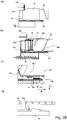
- a main assembly of the copying machine main assembly of the image forming apparatus or main assembly of the apparatus.
- Designated by 101 is an original which is placed on an original supporting platen glass 102.
- a light image corresponding to image information of the original is imaged on an electrophotographic photosensitive member 104 (photosensitive member) by way of a plurality of mirrors M of an optical portion 103 and a lens Ln, so that an electrostatic latent image is formed.
- the electrostatic latent image is visualized with toner (one component magnetic toner) as a developer (dry powder) by a dry type developing device (one component developing device) 201a.
- the one component magnetic toner is used as the developer to be supplied from a developer supply container 1, but the present invention is not limited to the example and includes other examples which will be described hereinafter.
- the one component non-magnetic toner is supplied as the developer.
- the non-magnetic toner is supplied as the developer.
- both of the non-magnetic toner and the magnetic carrier may be supplied as the developer.
- cassettes accommodating recording materials (sheets) S are cassettes accommodating recording materials (sheets) S.
- sheets recording materials
- an optimum cassette is selected on the basis of a sheet size of the original 101 or information inputted by the operator (user) from a liquid crystal operating portion of the copying machine.
- the recording material is not limited to a sheet of paper, but OHP sheet or another material can be used as desired.
- One sheet S supplied by a separation and feeding device 105A-108A is fed to registration rollers 110 along a feeding portion 109, and is fed at timing synchronized with rotation of a photosensitive member 104 and with scanning of an optical portion 103.
- Designated by 111, 112 are a transfer charger and a separation charger. An image of the developer formed on the photosensitive member 104 is transferred onto the sheet S by a transfer charger 111. Then, the sheet S carrying the developed image (toner image) transferred thereonto is separated from the photosensitive member 104 by the separation charger 112.
- the sheet S fed by the feeding portion 113 is subjected to heat and pressure in a fixing portion 114 so that the developed image on the sheet is fixed, and then passes through a discharging/reversing portion 115, in the case of one-sided copy mode, and subsequently the sheet S is discharged to a discharging tray 117 by discharging rollers 116.
- the sheet S enters the discharging/reversing portion 115 and a part thereof is ejected once to an outside of the apparatus by the discharging roller 116.
- the trailing end thereof passes through a flapper 118, and a flapper 118 is controlled when it is still nipped by the discharging rollers 116, and the discharging rollers 116 are rotated reversely, so that the sheet S is refed into the apparatus.
- the sheet S is fed to the registration rollers 110 by way of re-feeding portions 119, 120, and then conveyed along the path similarly to the case of the one-sided copy mode and is discharged to the discharging tray 117.
- image forming process equipment such as a developing device 201a as the developing means a cleaner portion 202 as a cleaning means, a primary charger 203 as charging means.
- the developing device 201a develops the electrostatic latent image formed on the photosensitive member 104 by the optical portion 103 in accordance with image information of the 101, by depositing the developer onto the latent image.
- the primary charger 203 uniformly charges a surface of the photosensitive member for the purpose of forming a desired electrostatic image on the photosensitive member 104.
- the cleaner portion 202 removes the developer remaining on the photosensitive member 104.
- Figure 2 is an outer appearance of the image forming apparatus.
- an exchange front cover 40 which is a part of an outer casing of the image forming apparatus, a part of a developer replenishing apparatus 8 which will be described hereinafter appears.
- the front cover 40 for the exchange is a cover exclusively for mounting and demounting (exchanging) the developer supply container 1 and is opened and closed only for mounting and demounting the developer supply container 1. In the maintenance operation for the main assembly of the device 100, a front cover 100c is opened and closed.
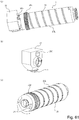
- Figure 3 is a schematic perspective view of the developer replenishing apparatus 8.
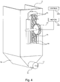
- Figure 4 is a schematic perspective view of the developer replenishing apparatus 8 as seen from the backside.
- Figure 5 is a schematic sectional view of the developer replenishing apparatus 8.
- the developer replenishing apparatus 8 is provided with a mounting portion (mounting space) to which the developer supply container 1 is demountable (detachably mountable). It is provided also with a developer receiving port (developer receiving hole) for receiving the developer discharged from a discharge opening (discharging port) 1c of the developer supply container 1 which will be described hereinafter.
- a diameter of the developer receiving port 8a is desirably substantially the same as that of the discharge opening 1c of the developer supply container 1 from the standpoint of preventing as much as possible contamination of the inside of a mounting portion 8f with the developer.
- the developer receiving port 8a is a minute opening (pin hole) correspondingly to the discharge opening 1c of the developer supply container 1, and the diameter is approx. 2 mm ⁇ .
- a L-shaped positioning guide (holding member) 8b for fixing a position of the developer supply container 1, so that the mounting direction of the developer supply container 1 to the mounting portion 8f is the direction indicated by an arrow A.
- the removing direction of the developer supply container 1 from the mounting portion 8f is opposite to the direction of arrow A.
- the developer replenishing apparatus 8 is provided in the lower portion with a hopper 8 g for temporarily accumulates the developer As shown in Figure 5 .
- a feeding screw 11 for feeding the developer into the developer hopper portion 201a which is a part of the developing device 201, and an opening 8e in fluid communication with the developer hopper portion 201a.
- a feeding screw 11 for feeding the developer into the developer hopper portion 201a which is a part of the developing device 201, and an opening 8e in fluid communication with the developer hopper portion 201a.
- a volume of the hopper 8 g is 130 cm ⁇ 3.
- the developing device 201 of Figure 1 develops, using the developer, the electrostatic latent image formed on the photosensitive member 104 on the basis of image information of the original 101.
- the developing device 201 is provided with a developing roller 201f in addition to the developer hopper portion 201a.
- the developer hopper portion 201a is provided with a stirring member 201c for stirring the developer supplied from the developer supply container 1.
- the developer stirred by the stirring member 201c is fed to the feeding member 201e by a feeding member 201d.
- the developer fed sequentially by the feeding members 201e, 201b is carried on the developing roller 201f, and is finally to the photosensitive member 104.
- the developer replenishing apparatus 8 is further provided with a locking member 9 and a gear 10 which constitute a driving mechanism for driving the developer supply container 1 which will be described hereinafter.
- the locking member 9 is locked with a holding member 3 (which will be described hereinafter) functioning as a drive inputting portion for the developer supply container 1 when the developer supply container 1 is mounted to the mounting portion 8f for the developer replenishing apparatus 8.
- the locking member 9 is loosely fitted in an elongate hole portion 8c formed in the mounting portion 8f of the developer replenishing apparatus 8, and movable up and down directions in the Figure relative to the mounting portion 8f.
- the locking member 9 is in the form of a round bar configuration and is provided at the free end with a tapered portion 9d in consideration of easy insertion into a holding member 3 ( Figure 9 ) of the developer supply container 1 which will be described hereinafter.
- the locking portion 9a (engaging portion engageable with holding member 3) of the locking member 9 is connected with a rail portion 9b shown in Figure 4 , and the sides of the rail portion 9b are held by a guide portion 8d of the developer replenishing apparatus 8 and is movable in the up and down direction in the Figure.
- the rail portion 9b is provided with a gear portion 9c which is engaged with a gear 10.
- the gear 10 is connected with a driving motor 500.
- a control device 600 effecting such a control that the rotational moving direction of a driving motor 500 provided in the image forming apparatus 100 is periodically reversed, the locking member 9 reciprocates in the up and down directions in the Figure along the elongated hole 8c.
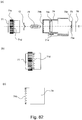
- Figure 6 is a block diagram illustrating the function and the structure of the control device 600
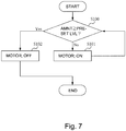
- Figure 7 is a flow chart illustrating a flow of the supplying operation.
- an amount of the developer temporarily accumulated in the hopper 8 g (height of the developer level) is limited so that the developer does not flow reversely into the developer supply container 1 from the developer replenishing apparatus 8 by the suction operation of the developer supply container 1 which will be described hereinafter.
- a developer sensor 8k ( Figure 5 ) is provided to detect the amount of the developer accommodated in the hopper 8g.
- the control device 600 controls the operation/non-operation of the driving motor 500 in accordance with an output of the developer sensor 8k by which the developer is not accommodated in the hopper 8 g beyond a predetermined amount. A flow of a control sequence therefor will be described.
- the developer sensor 8k checks the accommodated developer amount in the hopper 8g.
- the driving motor 500 is actuated to execute a developer supplying operation for a predetermined time period (S101).
- the accommodated developer amount detected with developer sensor 8k is discriminated as having reached the predetermined amount, that is, when the developer is detected by the developer sensor 8k, as a result of the developer supplying operation, the driving motor 500 is deactuated to stop the developer supplying operation (S102). By the stop of the supplying operation, a series of developer supplying steps is completed.
- Such developer supplying steps are carried out repeatedly whenever the accommodated developer amount in the hopper 8 g becomes less than a predetermined amount as a result of consumption of the developer by the image forming operations.
- the developer discharged from the developer supply container 1 is stored temporarily in the hopper 8g, and then is supplied into the developing device 201, but the following structure of the developer replenishing apparatus can be employed.
- the main assembly is required to be compact and low in cost.
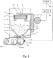
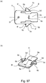
- it is desirable that the developer is supplied directly to the developing device 201, as shown in Figure 8 . More particularly, the above-described hopper 8 g is omitted, and the developer is supplied directly into the developing device 201a from the developer supply container 1.
- Figure 8 shows an example using a two component developing device 201 a developer replenishing apparatus.
- the developing device 201 comprises a stirring chamber into which the developer is supplied, and a developer chamber for supplying the developer to the developing roller 201f, wherein the stirring chamber and the developer chamber are provided with stirring member (screws) 201d rotatable in such directions that the developer is fed in the opposite directions from each other.
- the stirring chamber and the developer chamber are communicated with each other in the opposite longitudinal end portions, and the two component developer are circulated the two chambers.
- the stirring chamber is provided with a magnetometric sensor 201 g for detecting a toner content of the developer, and on the basis of the detection result of the magnetometric sensor 201g, the control device 600 controls the operation of the driving motor 500.
- the developer supplied from the developer supply container is non-magnetic toner or non-magnetic toner plus magnetic carrier.
- the developer in the developer supply container 1 is hardly discharged through the discharge opening 1c only by the gravitation, but the developer is by a discharging operation by a pump portion 2, and therefore, variation in the discharge amount can be suppressed. Therefore, the developer supply container 1 which will be described hereinafter is usable for the example of Figure 8 lacking the hopper 8g.
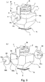
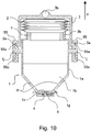
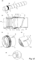
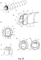
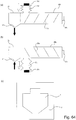
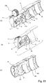
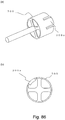
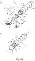
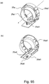
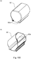
- FIG. 9 Part (a) of Figure 9 is a schematic perspective view of the developer supply container 1 the and part (b) of Figure 9 is an exploded view illustrating the developer supply container 1 from which a locking member 55 has been removed.
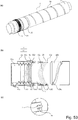
- Figure 10 is a schematic sectional view of the developer supply container 1.
- the developer supply container 1 has a container body 1a functioning as a developer accommodating portion for accommodating the developer.
- Designated by 1b in Figure 10 is a developer accommodating space in which the developer is accommodated in the container body 1a.
- the developer accommodating space 1b functioning as the developer accommodating portion is the space in the container body 1a plus an inside space in the pump portion 2.
- the developer accommodating space 1b accommodates toner which is dry powder having a volume average particle size of 5 ⁇ m - 6 ⁇ m.
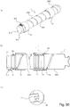
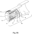
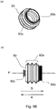
- the pump portion is a displacement type pump portion 2 in which the volume changes. More particularly, the pump portion 2 has a bellow-like expansion-and-contraction portion 2a (bellow portion, expansion-and-contraction member) which can be contracted and expanded by a driving force received from the developer replenishing apparatus 8. More particularly, the pump portion 2 has a bellow-like expansion-and-contraction portion 2a (bellow portion, expansion-and-contraction member) which can be contracted and expanded by a driving force received from the developer replenishing apparatus 8.
- the expansion-and-contraction portion 2a of the pump portion 2 is a volume changing portion which changes the internal pressure of the container body 1a by increasing and decreasing the volume.
- the bellow-like pump portion 2 of this example is folded to provide crests and bottoms which are provided alternately and periodically, and is contractable and expandable.
- a variation in the volume change amount relative to the amount of expansion and contraction can be reduced, and therefore, a stable volume change can be accomplished.
- the entire volume of the developer accommodating space 1b is 480 cm ⁇ 3, of which the volume of the pump portion 2 is 160 cm ⁇ 3 (in the free state of the expansion-and-contraction portion 2a), and in this example, the pumping operation is effected in the pump portion (2) expansion direction from the length in the free state.
- the volume change amount by the expansion and contraction of the expansion-and-contraction portion 2a of the pump portion 2 is 15 cm ⁇ 3, and the total volume at the time of maximum expansion of the pump portion 2 is 495 cm ⁇ 3.
- the developer supply container 1 filled with 240 g of developer.
- the driving motor 500 for driving the locking member 9 is controlled by the control device 600 to provide a volume change speed of 90 cm ⁇ 3/s.
- the volume change amount and the volume change speed may be properly selected in consideration of a required discharge amount of the developer replenishing apparatus 8.
- the pump portion 2 in this example is a bellow-like pump, but another pump is usable if the air amount (pressure) in the developer accommodating space 1b can be changed.
- the pump portion 2 may be a single-shaft eccentric screw pump.
- an additional opening is required to permit suction and discharging by the single-shaft eccentric screw pump is necessary, and the provision of the opening requires means such as a filter for preventing leakage of the developer around the opening.
- a single-shaft eccentric screw pump requires a very high torque to operate, and therefore, the load to the main assembly 100 of the image forming apparatus increases. Therefore, the bellow-like pump is preferable since it is free of such problems.
- the developer accommodating space 1b may be only the inside space of the pump portion 2. In such a case, the pump portion 2 functions simultaneously as the developer accommodating space 1b.
- a connecting portion 2b of the pump portion 2 and the connected portion 1i of the container body 1a are unified by welding to prevent leakage of the developer, that is, to keep the hermetical property of the developer accommodating space 1b.
- the developer supply container 1 is provided with a portion-to-be-engaged 3b which is integral with the holding portion 3 which will be described hereinafter, as a drive inputting portion (driving force receiving portion, drive connecting portion, engaging portion) which is engageable with the driving mechanism of the developer replenishing apparatus 8 and which receives a driving force for driving the pump portion 2 from the driving mechanism.
- a drive inputting portion driving force receiving portion, drive connecting portion, engaging portion
- the portion-to-be-engaged 3b engageable with the locking member 9 of the developer replenishing apparatus 8 is mounted to an upper end of the pump portion 2.
- the locking member 9 is inserted into the portion-to-be-engaged 3b, so that they are unified (slight play is provided for easy insertion).
- the relative position between the portion-to-be-engaged 3b and the locking member 9 in arrow p direction and arrow q direction which are expansion and contracting directions of the expansion-and-contraction portion 2a.
- the pump portion 2 and the portion-to-be-engaged 3b are molded integrally using an injection molding method or a blow molding method.
- the portion-to-be-engaged 3b unified substantially with the locking member 9 in this manner receives a driving force for expanding and contracting the expansion-and-contraction portion 2a of the pump portion 2 from the locking member 9.
- the expansion-and-contraction portion 2a of the pump portion 2 is expanded and contracted.
- the pump portion 2 functions as a air flow generating mechanism for producing alternately and repeatedly the air flow into the developer supply container and the air flow to the outside of the developer supply container through the discharge opening 1c by the driving force received by the portion-to-be-engaged 3b functioning as the drive inputting portion.
- the use is made with the round bar locking member 9 and the round hole portion-to-be-engaged 3b to substantially unify them, but another structure is usable if the relative position therebetween can be fixed with respect to the expansion and contracting direction (arrow p direction and arrow q direction) of the expansion-and-contraction portion 2a.
- the portion-to-be-engaged 3b is a rod-like member
- the locking member 9 is a locking hole
- the cross-sectional configurations of the portion-to-be-engaged 3b and the locking member 9 may be triangular, rectangular or another polygonal, or may be ellipse, star shape or another shape.
- another known locking structure is usable.
- a discharge opening 1c for permitting discharging of the developer in the developer accommodating space 1b to the outside of the developer supply container 1 is provided.
- the discharge opening 1c will be described in detail hereinafter.
- an inclined surface 1f is formed toward the discharge opening 1c in a lower portion of the container body 1a, the developer accommodated in the developer accommodating space 1b slides down on the inclined surface 1f by the gravity toward a neighborhood of the discharge opening 1c
- the inclination angle of the inclined surface 1f (angle relative to a horizontal surface in the state that the developer supply container 1 is set in the developer replenishing apparatus 8) is larger than an angle of rest of the toner (developer).
- the developer supply container 1 is in fluid communication with the outside of the developer supply container 1 only through the discharge opening 1c, and is sealed substantially except for the discharge opening 1c.
- a sealing member 4 of an elastic material is fixed by bonding to a lower surface of the flange portion 1 g so as to surround the circumference of the discharge opening 1c to prevent developer leakage.
- a shutter 5 for sealing the discharge opening 1c is provided so as to compress the sealing member 4 between the shutter 5 and a lower surface of the flange portion 1g.
- the shutter 5 is normally urged (by expanding force of a spring) in a close direction by a spring (not shown) which is an urging member.
- the shutter 5 is unsealed in interrelation with mounting operation of the developer supply container 1 by abutting to an end surface of the abutting portion 8h ( Figure 3 ) formed on the developer replenishing apparatus 8 and contracting the spring.
- the flange portion 1 g of the developer supply container 1 is inserted between an abutting portion 8h and the positioning guide 8b provided in the developer replenishing apparatus 8, so that a side surface 1k ( Figure 9 ) of the developer supply container 1 abuts to a stopper portion 8i of the developer replenishing apparatus 8.
- the position of the developer supply container 1 relative to the developer replenishing apparatus 8 in the mounting direction (A direction) is determined ( Figure 17 ).
- the flange portion 1 g is guided by the positioning guide 8b in this manner, and at the time when the inserting operation of the developer supply container 1 is completed, the discharge opening 1c and the developer receiving port 8a are aligned with each other.
- the locking member 9 is inserted into the portion-to-be-engaged 3b of the holding member 3 of the developer supply container 1 so that they are unified.
- the position thereof is determined by the L shape portion of the positioning guide 8b in the direction (up and down direction in Figure 3 ) perpendicular to the mounting direction (A direction), relative to the developer replenishing apparatus 8, of the developer supply container 1.
- the flange portion 1 g as the positioning portion also functions to prevent movement of the developer supply container 1 in the up and down direction (reciprocating direction of the pump portion 2).
- the operations up to here are the series of mounting steps for the developer supply container 1. By the operator closing the front cover 40, the mounting step is finished.
- the steps for dismounting the developer supply container 1 from the developer replenishing apparatus 8 are opposite from those in the mounting step.
- the exchange front cover 40 is opened, and the developer supply container 1 is dismounted from the mounting portion 8f. At this time, the interfering state by the abutting portion 8h is released, by which the shutter 5 is closed by the spring (not shown).
- the state (decompressed state, negative pressure state) in which the internal pressure of the container body 1a (developer accommodating space 1b) is lower than the ambient pressure (external air pressure) and the state (compressed state, positive pressure state) in which the internal pressure is higher than the ambient pressure are alternately repeated at a predetermined cyclic period.
- the ambient pressure (external air pressure) is the pressure under the ambient condition in which the developer supply container 1 is placed.
- the developer is discharged through the discharge opening 1c by changing a pressure (internal pressure) of the container body 1a. In this example, it is changed (reciprocated) between 480 - 495 cm ⁇ 3 at a cyclic period of 0.3 sec.
- the material of the container body 1 is preferably such that it provides an enough rigidity to avoid collision or extreme expansion.
- this example employs polystyrene resin material as the materials of the developer container body 1a and employs polypropylene resin material as the material of the pump portion 2.
- the material for the container body 1a other resin materials such as ABS (acrylonitrile, butadiene, styrene copolymer resin material), polyester, polyethylene, polypropylene, for example are usable if they have enough durability against the pressure. Alternatively, they may be metal.
- ABS acrylonitrile, butadiene, styrene copolymer resin material
- polyester polyethylene
- polypropylene for example are usable if they have enough durability against the pressure.
- they may be metal.
- any material is usable if it is expansible and contractable enough to change the internal pressure of the space in the developer accommodating space 1b by the volume change.
- the examples includes thin formed ABS (acrylonitrile, butadiene, styrene copolymer resin material), polystyrene, polyester, polyethylene materials.
- other expandable-and-contractable materials such as rubber are usable.
- They may be integrally molded of the same material through an injection molding method, a blow molding method or the like if the thicknesses are properly adjusted for the pump portion 2b and the container body 1a.
- the developer supply container 1 is in fluid communication with the outside only through the discharge opening 1c, and therefore, it is substantially sealed from the outside except for the discharge opening 1c. That is, the developer is discharged through discharge opening 1c by compressing and decompressing the inside of the developer supply container 1, and therefore, the hermetical property is desired to maintain the stabilized discharging performance.
- the internal pressure of the container may abruptly changes due to abrupt variation of the ambient conditions.
- the inside of the developer supply container 1 may be pressurized as compared with the ambient air pressure. In such a case, the container may deform, and/or the developer may splash when the container is unsealed.
- the developer supply container 1 is provided with an opening of a diameter ⁇ 3 mm, and the opening is provided with a filter, in this example.
- the filter is TEMISH (registered Trademark) available from Nitto Denko Kabushiki Kaisha, Japan, which is provided with a property preventing developer leakage to the outside but permitting air passage between inside and outside of the container.
- TEMISH registered Trademark
- the influence thereof to the sucking operation and the discharging operation through the discharge opening 1c by the pump portion 2 can be ignored, and therefore, the hermetical property of the developer supply container 1 is kept in effect.
- the size of the discharge opening 1c of the developer supply container 1 is so selected that in the orientation of the developer supply container 1 for supplying the developer into the developer replenishing apparatus 8, the developer is not discharged to a sufficient extent, only by the gravitation.
- the opening size of the discharge opening 1c is so small that the discharging of the developer from the developer supply container is insufficient only by the gravitation, and therefore, the opening is called pin hole hereinafter.
- the size of the opening is determined such that the discharge opening 1c is substantially clogged.
- the inventors have investigated as to the size of the discharge opening 1c not enough to discharge the toner to a sufficient extent only by the gravitation.
- the verification experiment (measuring method) and criteria will be described.
- a rectangular parallelepiped container of a predetermined volume in which a discharge opening (circular) is formed at the center portion of the bottom portion is prepared, and is filled with 200 g of developer; then, the filling port is sealed, and the discharge opening is plugged; in this state, the container is shaken enough to loosen the developer.
- the rectangular parallelepiped container has a volume of 1000 cm ⁇ 3, 90 mm in length, 92 mm width and 120 mm in height.
- the discharge opening is unsealed in the state that the discharge opening is directed downwardly, and the amount of the developer discharged through the discharge opening is measured.
- the rectangular parallelepiped container is sealed completely except for the discharge opening.
- the verification experiments were carried out under the conditions of the temperature of 24 degree C and the relative humidity of 55 %.
- the discharge amounts are measured while changing the kind of the developer and the size of the discharge opening.
- the amount of the discharged developer is not more than 2g, the amount is negligible, and therefore, the size of the discharge opening at that time is deemed as being not enough to discharge the developer sufficiently only by the gravitation.
- the developers used in the verification experiment are shown in Table 1.
- the kinds of the developer are one component magnetic toner, non-magnetic toner for two component developer developing device and a mixture of the non-magnetic toner and the magnetic carrier.
- the measurements are made as to angles of rest indicating flowabilities, and fluidity energy indicating easiness of loosing of the developer layer, which is measured by a powder flowability analyzing device (Powder Rheometer FT4 available from Freeman Technology).
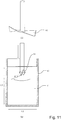
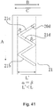
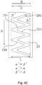
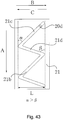
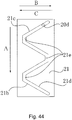
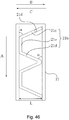
- Figure 11 is a schematic view of a device for measuring the fluidity energy.
- the principle of the powder flowability analyzing device is that a blade is moved in a powder sample, and the energy required for the blade to move in the powder, that is, the fluidity energy, is measured.
- the blade is of a propeller type, and when it rotates, it moves in the rotational axis direction simultaneously, and therefore, a free end of the blade moves helically.
- the fluidity energy is total energy provided by integrating with time a total sum of a rotational torque and a vertical load when the helical rotating blade 51 enters the powder layer and advances in the powder layer.
- the value thus obtained indicates easiness of loosening of the developer powder layer, and large fluidity energy means less easiness and small fluidity energy means greater easiness.
- the filling amount is adjusted in accordance with a bulk density of the developer to measure
- the blade 54 of ⁇ 48 mm which is the standard part is advanced into the powder layer, and the energy required to advance from depth 10 mm to depth 30 mm is displayed.
- the set conditions at the time of measurement are, The set conditions at the time of measurement are,
- the blade advancing speed in the vertical direction into the powder layer is such a speed that an angle ⁇ (helix angle) formed between a track of the outermost edge portion of the blade 51 during advancement and the surface of the powder layer is 10°:
- the measurement is carried out under the condition of temperature of 24 degree C and relative humidity of 55 %.
- the bulk density of the developer when the fluidity energy of the developer is measured is close to that when the experiments for verifying the relation between the discharge amount of the developer and the size of the discharge opening, is less changing and is stable, and more particularly is adjusted to be 0.5g/cm ⁇ 3.
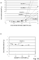
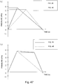
- Part (a) of Figure 12 is a graph showing relations between the diameters of the discharge openings and the discharge amounts with respect to the respective developers.
- the diameter ⁇ of the discharge opening is preferably not more than 4 mm (12.6 mm ⁇ 2 of the opening area) when the fluidity energy of the developer (0.5g/cm ⁇ 3 of the bulk density) is not less than 4.3x 10 - 4 kg-m ⁇ 2/s ⁇ 2 (J) and not more than 4.14x 10 ⁇ -3 kg-m ⁇ 2/s ⁇ 2 (J).
- the bulk density of the developer As for the bulk density of the developer, the developer has been loosened and fluidized sufficiently in the verification experiments, and therefore, the bulk density is lower than that expected in the normal use condition (left state), that is, the measurements are carried out in the condition in which the developer is more easily discharged than in the normal use condition.
- the verification experiments were carries out as to the developer A with which the discharge amount is the largest in the results of part (a) of Figure 12 , wherein the filling amount in the container were changed in the range of 30 - 300 g while the diameter ⁇ of the discharge opening is constant at 4 mm.
- the verification results are shown in part (b) of Figure 12 . From the results of part (b) Figure 12 , it has been confirmed that the discharge amount through the discharge opening hardly changes even if the filling amount of the developer changes.
- the lower limit value of the size of the discharge opening 1c is preferably such that the developer to be supplied from the developer supply container 1 (one component magnetic toner, one component non-magnetic toner, two component non-magnetic toner or two component magnetic carrier) can at least pass therethrough.
- the discharge opening is preferably larger than a particle size of the developer (volume average particle size in the case of toner, number average particle size in the case of carrier) contained in the developer supply container 1.
- the discharge opening is larger than a larger particle size, that is, the number average particle size of the two component magnetic carrier.
- the diameter of the discharge opening 1c is preferably not less than 0.05 mm (0.002 mm ⁇ 2 in the opening area).
- the diameter ⁇ of the discharge opening 3a is preferably not less than 0.5 mm.
- the configuration of the discharge opening 1c is circular, but this is not inevitable.
- a square, a rectangular, an ellipse or a combination of lines and curves or the like are usable if the opening area is not more than 12.6 mm ⁇ 2 which is the opening area corresponding to the diameter of 4 mm.
- a circular discharge opening has a minimum circumferential edge length among the configurations having the same opening area, the edge being contaminated by the deposition of the developer. Therefore, the amount of the developer dispersing with the opening and closing operation of the shutter 5 is small, and therefore, the contamination is decreased.
- the configuration of the discharge opening 1c is preferably circular which is excellent in the balance between the discharge amount and the contamination prevention.
- the size of the discharge opening 1c is preferably such that the developer is not discharged sufficiently only by the gravitation in the state that the discharge opening 1c is directed downwardly (supposed supplying attitude into the developer replenishing apparatus 8). More particularly, a diameter ⁇ of the discharge opening 1c is not less than 0.05 mm (0.002 mm ⁇ 2 in the opening area) and not more than 4 mm (12.6 mm ⁇ 2 in the opening area). Furthermore, the diameter ⁇ of the discharge opening 1c is preferably not less than 0.5 mm (0.2 mm ⁇ 2 in the opening area and not more than 4 mm (12.6 mm ⁇ 2 in the opening area). In this example, on the basis of the foregoing investigation, the discharge opening 1c is circular, and the diameter ⁇ of the opening is 2 mm.
- the number of discharge openings 1c is one, but this is not inevitable, and a plurality of discharge openings 1c a total opening area of the opening areas satisfies the above-described range.
- a plurality of discharge openings 1c a total opening area of the opening areas satisfies the above-described range.
- two discharge openings 3a each having a diameter ⁇ of 0.7 mm are employed.
- the discharge amount of the developer per unit time tends to decrease, and therefore, one discharge opening 1c having a diameter ⁇ of 2 mm is preferable.
- a regulating portion for regulating a volume change of the pump2.
- the regulating portion regulates of the position upon the start of the operation of the pump portion 2 (expansion and contraction state) so that in the initial operation period of the cyclic period of the pump portion 2, the air is supplied into the inside of the developer accommodating space 1b through the discharge opening 1c.
- the initial operation period of the pump is the first period when the developer is to be discharged through the discharge opening after a new developer supply container is mounted to the developer receiving apparatus.
- the regulating portion of the pump portion 2 comprises the holding member 3 and the locking member (member-to-be-engaged) 55, and the holding member 3 is regulated to be immovable by engaging with the locking member 55.
- the holding member 3 has a channel shaped, and extends at upper end surface of the pump portion 2 toward both side surfaces of the container body 1a.
- An engaging projection 3a is provided on the holding member 3 adjacent the container body 1a. Further, as described above, the portion-to-be-engaged 3b is engaged with the locking portion 9a of the locking member9.
- the locking member 55 is rotatable relative to the container body 1a since a supporting portion 55c thereof is rotatably engaged with the rotational axis 1j provided on each of the sides of the container body 1a.
- the locking member 55 is provided with an engaging groove (portion-to-be-engaged) 55a which is engaged by the engaging projection (engaging portion) 3a of the holding member 3, and with an engaging groove (portion-to-be-engaged) 55b which is engaged by an engaging projection (engaging portion) 8j ( Figure 3 ) of the developer replenishing apparatus8.
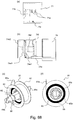
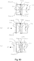
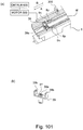
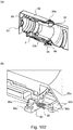
- Parts (a) and (b) of Figure 13 illustrate a state of various parts in the process of mounting the developer supply container 1, and parts (a) and (b) of Figure 14 illustrate a state of various parts at the time of completion of the mounting of the developer supply container 1.
- the developer supply container 1 is regulated in the state of contraction of the pump portion 2 before it is mounted to the developer replenishing apparatus 8.
- the engaging projection 3a of the holding member 3 is engaged with the engaging groove 55a provided in the locking member 55, and the holding member 3 receives an urging force in the direction of the arrow p by an elastic restoring force of the pump2.
- a frictional force is provided between the rotation supporting portion 55c and the rotational axis 1j so that the locking member 55 is prevented from rotating unintentionally during the transportation or by an erroneous operation.
- the locking portion 9a of the locking member 9 is brought into engagement with the portion-to-be-engaged 3b of the holding member 3 partway of the insertion, as shown in part (a) of Figure 13 .
- the flange portion 1 g of the developer supply container 1 engaging with the positioning guide 8b of the developer replenishing apparatus 8, the discharge opening (developer supply opening) 1c is aligned with the developer receiving port 8a.
- the engaging projection 8j of the developer replenishing apparatus 8 engages into the engaging groove 55b of the locking member 55.
- the engaging projection 8j pushes a wall 55b1 of the engaging groove 55b to rotate the locking member 55 in the direction of an arrow F in the Figure.
- the locking member 55 is in the position shown in part (b) of Figure 14 , so that the engaging projection 3a becomes movable from the detachable engaging groove 55a in the direction of the arrow p, so that the limiting to the pump portion 2 is released.
- the mounting operation developer supply container 1 is completed when the discharge opening (developer supply opening) 1c is brought into communication with the developer receiving port 8a.
- the dismounting of the developer supply container 1 is accomplished through the opposite order. More specifically, when the supplying operation ends, the locking member 9 is controlled to be at the position of the mounting, and therefore, the engaging projection 3a is in the engaging groove 55a as shown in part (b) of Figure 14 .
- the engaging projection 8j of the developer replenishing apparatus 8 pushes a wall 55b2 of the engaging groove 55a to rotate the locking member 55 in the opposite direction, that is, the direction of arrow F.
- the engaging projection 3a engages into the engaging groove 55a, so that the movement of the engaging projection 3a is limited. Therefore, the operation the pump portion 2 is limited, as a result.
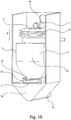
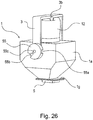
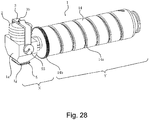
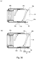
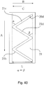
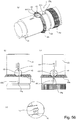
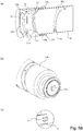
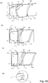
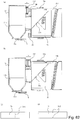
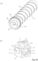
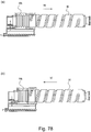
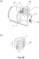
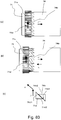
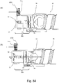
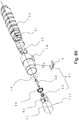
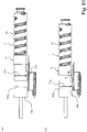
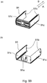
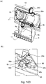
- Figure 15 is a schematic perspective view in which the expansion-and-contraction portion 2a of the pump portion 2 is contracted.
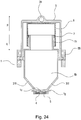
- Figure 16 is a schematic perspective view in which the expansion-and-contraction portion 2a of the pump portion 2 is expanded.
- Figure 17 is a schematic sectional view in which the expansion-and-contraction portion 2a of the pump portion 2 is contracted.
- Figure 18 is a schematic sectional view in which the expansion-and-contraction portion 2a of the pump portion 2 is expanded.
- the drive conversion of the rotational force is carries out by the drive converting mechanism so that the suction step (suction operation through discharge opening 3a) and the discharging step (discharging operation through the discharge opening 3a) are repeated alternately.
- the suction step and the discharging step will be described.
- the operation principle of the expansion-and-contraction portion 2a of the pump portion 2 is as has been in the foregoing.
- the lower end of the expansion-and-contraction portion 2a is connected to the container body 1a.
- the container body 1a is prevented in the movement in the p direction and in the q direction ( Figure 9 ) by the positioning guide 8b of the developer supplying apparatus 8 through the flange portion 1 g at the lower end. Therefore, the vertical position of the lower end of the expansion-and-contraction portion 2a connected with the container body 1a is fixed relative to the developer replenishing apparatus 8.
- the upper end of the expansion-and-contraction portion 2a is engaged with the locking member 9 through the holding member 3, and is reciprocated in the p direction and in the q direction by the vertical movement of the locking member 9.
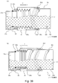
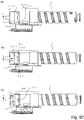
- the internal pressure of the developer accommodating space 1b becomes higher than the pressure in the hopper 8 g (substantially equivalent to the ambient pressure). That is, the internal pressure of the developer accommodating space 1b becomes higher than the ambient pressure. Therefore, as shown in Figure 17 , the developer T is pushed out by the air pressure due to the pressure difference (difference pressure relative to the ambient pressure). Thus, the developer T is discharged from the developer accommodating space 1b into the hopper 8g.
- An arrow in Figure 17 indicates a direction of a force applied to the developer T in the developer accommodating space 1b.
- the air in the developer accommodating space 1b is also discharged together with the developer, and therefore, the internal pressure of the developer accommodating space 1b decreases.
- the internal pressure of the developer accommodating space 1b at this time becomes lower than the internal pressure in the hopper 8 g (substantially equivalent to the ambient pressure). More particularly the internal pressure of the developer accommodating space 1b becomes lower than the ambient pressure. Therefore, as shown in Figure 18 , the air in the upper portion in the hopper 8 g enters the developer accommodating space 1b through the discharge opening 1c by the pressure difference (difference pressure relative to the ambient pressure) between the developer accommodating space 1b and the hopper 8g.
- An arrow in Figure 18 indicates a direction of a force applied to the developer T in the developer accommodating space 1b.
- Ovals Z in Figure 18 schematically show the air taken in from the hopper 8g.
- the air is taken-in from the outside of the developer supply device 8, and therefore, the developer in the neighborhood of the discharge opening 1c can be loosened. More particularly, the air impregnated into the developer powder existing in the neighborhood of the discharge opening 1c, reduces the bulk density of the developer powder and fluidizing.
- the amount of the developer T (per unit time) discharged through the discharge opening 3a can be maintained substantially at a constant level for a long term.
- Verification experiments were carried out as to a change of the internal pressure of the developer supply container 1. The verification experiments will be described.
- the developer is filled such that the developer accommodating space 1b in the developer supply container 1 is filled with the developer; and the change of the internal pressure of the developer supply container 1 is measured when the pump portion 2 is expanded and contracted in the range of 15 cm ⁇ 3 of volume change.
- the internal pressure of the developer supply container 1 is measured using a pressure gauge (AP-C40 available from Kabushiki Kaisha KEYENCE) connected with the developer supply container 1.
- Figure 19 shows a pressure change when the pump portion 2 is expanded and contracted in the state that the shutter 5 of the developer supply container 1 filled with the developer is open, and therefore, in the communicatable state with the outside air.
- the abscissa represents the time, and the ordinate represents a relative pressure in the developer supply container 1 relative to the ambient pressure (reference (0)) (+ is a positive pressure side, and - is a negative pressure side).
- the internal pressure of the developer supply container 1 switches between the negative pressure and the positive pressure alternately by the suction operation and the discharging operation of the pump portion 2b, and the discharging of the developer is carried out properly.
- a simple and easy pump capable of effecting the suction operation and the discharging operation of the developer supply container 1 is provided, by which the discharging of the developer by the air can be carries out stably while providing the developer loosening effect by the air.
- the inside of the displacement type pump portion 2 is utilized as a developer accommodating space, and therefore, when the internal pressure is reduced by increasing the volume of the pump portion 2, an additional developer accommodating space can be formed. Therefore, even when the inside of the pump portion 2 is filled with the developer, the bulk density can be decreased (the developer can be fluidized) by impregnating the air in the developer powder. Therefore, the developer can be filled in the developer supply container 1 with a higher density than in the conventional art.
- the inside space in the pump portion 2 is used as a developer accommodating space 1b, but in an alternative, a filter which permits passage of the air but prevents passage of the toner may be provided to partition between the pump portion 2 and the developer accommodating space 1b.
- a filter which permits passage of the air but prevents passage of the toner may be provided to partition between the pump portion 2 and the developer accommodating space 1b.
- the embodiment described in the form of is preferable in that when the volume of the pump increases, an additional developer accommodating space can be provided.
- Verification has been carried out as to the developer loosening effect by the suction operation through the discharge opening 3a in the suction step.
- a low discharge pressure small volume change of the pump
- This verification is to demonstrate remarkable enhancement of the developer loosening effect in the structure of this example. This will be described in detail.
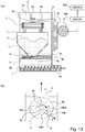
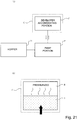
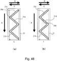
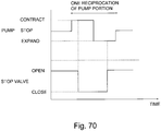
- Part (a) of Figure 20 and part (a) of Figure 21 are block diagrams schematically showing a structure of the developer supplying system used in the verification experiment.
- Part (b) of Figure 20 and part (b) of Figure 21 are schematic views showing a phenomenon-occurring in the developer supply container.
- the system of Figure 20 is analogous to this example, and a developer supply container C is provided with a developer accommodating portion C1 and a pump portion P.
- the suction operation and the discharging operation through a discharge opening (the discharge opening 1c of this example (unshown)) of the developer supply container C are carried out alternately to discharge the developer into a hopper H.
- the system of Figure 21 is a comparison example wherein a pump portion P is provided in the developer replenishing apparatus side, and by the expanding-and-contracting operation of the pump portion P, an air-supply operation into the developer accommodating portion C1 and the suction operation from the developer accommodating portion C1 are carried out alternately to discharge the developer into a hopper H.
- the developer accommodating portions C1 have the same internal volumes
- the hoppers H have the same internal volumes
- the pump portions P have the same internal volumes (volume change amounts).
- the developer supply container C is shaken for 15 minutes in view of the state later transportation, and thereafter, it is connected to the hopper H.
- the pump portion P is operated, and a peak value of the internal pressure in the suction operation is measured as a condition of the suction step required for starting the developer discharging immediately in the discharging step.
- the start position of the operation of the pump portion P corresponds to 480 cm ⁇ 3 of the volume of the developer accommodating portion C1
- the start position of the operation of the pump portion P corresponds to 480 cm ⁇ 3 of the volume of the hopper H.
- the hopper H is filled with 200 g of the developer beforehand to make the conditions of the air volume the same as with the structure of Figure 20 .
- the internal pressures of the developer accommodating portion C1 and the hopper H are measured by the pressure gauge (AP-C40 available from Kabushiki Kaisha KEYENCE) connected to the developer accommodating portion C1.
- the suction is carries out with the volume increase of the pump portion P, and therefore, the internal pressure of the developer supply container C can be lower (negative pressure side) than the ambient pressure (pressure outside the container), so that the developer solution effect is remarkably high.
- the volume increase of the developer accommodating portion C1 with the expansion of the pump portion P provides pressure reduction state (relative to the ambient pressure) of the upper portion air layer of the developer layer T. For this reason, the forces are applied in the directions to increase the volume of the developer layer T due to the decompression (wave line arrows), and therefore, the developer layer can be loosened efficiently.
- the air is taken in from the outside into the developer supply container C1 by the decompression (white arrow), and the developer layer T is solved also when the air reaches the air layer R, and therefore, it is a very good system.
- the apparent volume of the whole developer increases (the level of the developer rises).
- the developer can be discharged through the discharge opening 1c of the developer supply container 1. That is, in this example, the discharging operation and the suction operation are not in parallel or simultaneous, but are alternately repeated, and therefore, the energy required for the discharging of the developer can be minimized.
- the developer replenishing apparatus includes the air-supply pump and the suction pump, separately, it is necessary to control the operations of the two pumps, and in addition it is not easy to rapidly switch the air-supply and the suction alternately.
- one pump is effective to efficiently discharge the developer, and therefore, the structure of the developer discharging mechanism can be simplified.
- the discharging operation and the suction operation of the pump are repeated alternately to efficiently discharge the developer, but in an alternative structure, the discharging operation or the suction operation is temporarily stopped and then resumed.
- the discharging operation of the pump is not effected monotonically, but the compressing operation may be once stopped partway and then resumed to discharge.
- Each operation may be made in a multi-stage form as long as the discharge amount and the discharging speed are enough. It is still necessary that after the multi-stage discharging operation, the suction operation is effected, and they are repeated.
- the internal pressure of the developer accommodating space 1b is reduced to take the air through the discharge opening 1c to loosen the developer.
- the developer is loosened by feeding the air into the developer accommodating space 1b from the outside of the developer supply container 1, but at this time, the internal pressure of the developer accommodating space 1b is in a compressed state with the result of agglomeration of the developer.
- This example is preferable since the developer is loosened in the pressure reduced state in which is the developer is not easily agglomerated.
- the developer in the developer supply container 1 may be compacted by escape of the air during long term standing, for example.
- the developer is compacted with a higher possibility, due to the vibration imparted during the transportation to the user or long term standing under high temperature and high humidity conditions.
- the inside of the developer supply container 1 is pressurized by the volume reduction, and therefore, the inside developer is further compacted.
- the developer in the neighborhood of the discharge opening (developer supply opening) 1c clogs, by which a developer discharging defect may arise.
- a drive load required for operating the pump portion 2 increases.
- the first operation in the developer supplying operation of the developer supply container 1 is preferably to increase the volume of the pump portion 2 to take the air in.
- the state of the pump portion 2 before the start of the developer supplying operation can be regulated by the above-described regulating portion (holding member 3, locking member 55). More particularly, the position of the pump portion 2 upon the start of the operation can be regulated to the position shown in Figure 17 , so that the air is taken in the developer accommodating space 1b through the discharge opening 1c in the first operation period of the pump2. Therefore, the regulating portion of the developer supply container 1 can regulate the pump portion 2 in the contracted state the state shown in Figure 17 ), so that the supplying operation starts with the volume increasing stroke of the pump portion 2 with certainty.
- the developer loosening effect by the air introduction is most necessary at the time of use of a new developer supply container 1.
- the developer remaining in the developer supply container 1 may be compacted similarly.
- the position of the pump portion 2 at the time when the pump operation is resumed is the same as that at the time of the mounting, that is, the position is regulated so as to start the pump operation with the volume increasing stroke.
- the main assembly 100 of the apparatus 100 may be provided, for example, with a sensor for sensing the position of the locking member 9 of the developer replenishing apparatus 8 to stop the locking member 9 assuredly at the position which is the position the same as that upon the mounting of the developer supply container 1.
- the supplying operation can be started with the volume increasing stroke, if the portion-to-be-engaged 3b cam be engaged with the locking member 9 upon mounting of the developer supply container 1 to the developer replenishing apparatus8.
- the developer supply container 1 are not provided with the regulating portion, the position of the portion-to-be-engaged 3b before mounted to the developer supply container 8 cannot be regulated, and therefore, the user has to carry out the mounting operation of the portion-to-be-engaged 3b before while aligning for engagement between the locking member 9 and the portion-to-be-engaged 3b.
- the developer supply container 1 is provided with the regulating portion of the present invention, preferably.
- the regulation release and re- regulating operations for the pump portion 2 by the regulating portion is effected with the mounting and dismounting operation of the developer supply container 1 relative to the developer replenishing apparatus8.
- this is not inevitable, and it may be carried out in interrelation with the opening and closing operations of the exchange cover 40 ( Figure 2 ).
- the main assembly 100 of the apparatus 100 may be provided with an automatic operation mechanism, which is operated by a manipulation of an operation panel 100b ( Figure 2 ) of the main assembly 100 of the apparatus.
- the operation of the pump portion 2 can start with the volume increasing stroke normally. Therefore, even if the developer is compacted and caked in the neighborhood of the discharge opening (developer supply opening) 1c, the developer can be fluidized assuredly and can be discharged stably by introduction of the air from the start of the operation.
- the pump operation is started with the volume decreasing stroke in the state that the grooves of the bellows of the pump portion 2 contain the developer, the developer in the grooves are pressed further with possible result that a coagulated material and/or coarse particles which are influential to the image quality are produced.
- the pump operation starts with the volume increasing stroke, the amount of the developer in the grooves is small before the start of the pump operation, because the pump portion 2 has been set with the bellows contracted.
- the expanding stroke of the pump portion 2 does not compact the developer so that the production of the coagulated material and/or coarse particles can be avoided.
- the developer supply container 1 shown in Figure 9 is filled with 240 g of the developer. Thereafter, vibrations corresponding to the transportation are imparted with the discharge opening (developer supply opening) 1c at the bottom, thus compacting the developer. For the vibrations, the container is let fall from a height 30 mm 1000 times.
- the developer supply container 1 is mounted to the main assembly 100 of the apparatus, and the discharge opening 1c is unsealed, and then the supplying operation is carried out by operating the pump portion 2 under the condition of the volume change amount of 15 cm ⁇ 3 and the volume change speed of 90 cm ⁇ 3/s.
- the change of the internal pressure of the developer supply container 1 is measured.
- the internal pressure is measured by connecting a pressure gauge by the pressure gauge (AP-C40 available from Kabushiki Kaisha KEYENCE) connected to the developer accommodating portion.
- experiment example 1 the supplying operation by the developer supply container 1 is started with the stroke from the most contracted state toward the volume increasing state of the pump2. As a result, the developer is discharged from the developer supply container 1 from immediately after operation of the pump portion 2, and no problem arises up to the completion of the discharging.
- Part (a) of Figure 22 shows the change of the internal pressure of the developer supply container 1 upon the start of the discharging.
- the experiment similar to the experiment example 1 is carried out in the state that the discharge opening 1c is sealed to prevent the introduction of the air into the developer supply container 1 (hermetically sealed state).
- the internal pressure of the developer supply container 1 becomes negative relative to the outside ambient pressure, but in the end of the volume decreasing operation of the developer supply container 1 thereafter, the internal pressure of the developer supply container 1 becomes equivalent to the ambient pressure, that is, does not become positive.
- An absolute value of the pressure peak (maximum value) P1 of the negative pressure side at this time is 2.5kPa.
- the pressure P1 is lower than P2 (PI > P2
- the pump portion 2 is started for the supplying operation of the developer supply container 1 in the volume increasing direction from a state that the pump portion 2 is contracted halfway relative to the maximum expansion state.
- the other conditions are the same as with experiment examplel.
- the developer is not sufficiently discharged from the developer supply container 1 immediately after the operation start of the pump portion 2, but after several times pump operations, the developer is discharged stably, and finally, the operation is completely with no problem.
- Part (a) of Figure 22 shows the change of the internal pressure of the developer supply container 1 upon the start of the discharging.
- the change of the internal pressure is similar to experiment example 1, but the absolute value of the pressure peak of the negative pressure side is 2.0kPa, which is higher than the pressure value in the experiment examplel. This is because with the structure of experiment example 2, the amount of the volume change of the pump portion 2 is smaller than with experiment example 1, and therefore, the amount of the air taken in through the discharge opening 1c is smaller, and the expansion of the air in developer supply container 1 is less than in experiment example 1.
- a comparative example 1 the supplying operation of the developer supply container 1 is started with the stroke of volume decrease from the most expanded state of the pump2.
- the other conditions are the same as with experiment examplel.
- the developer is not discharged from the developer supply container 1, and a developer supply container replacement message is displayed 90 sec after. Thereafter, the supplying operation was continued for 180 sec approx., but the developer was not discharged.
- Part (b) of Figure 22 shows the change of the internal pressure of the developer supply container 1 upon the start of the discharging.
- the internal pressure of the developer supply container 1 becomes positive relative to the outside ambient pressure, but thereafter, in the end of the volume increasing operation of the developer supply container 1, the internal pressure of the developer supply container 1 becomes equivalent to the ambient pressure.
- the discharge opening (developer supply opening) 1c is sealed.
- Figure 23 is a schematic perspective view of a developer supply container 1
- Figure 24 is a schematic sectional view of the developer supply container 1.
- the structure of the pump is different from that of Embodiment 1, and the other structures are substantially the same as with Embodiment 1.
- the same reference numerals as in Embodiment 1 are assigned to the elements having the corresponding functions in this embodiment, and the detailed description thereof is omitted.
- a plunger type pump is used in place of the bellow-like displacement type pump as in Embodiment 1.
- the plunger pump of this example is also a volume changing portion which changes the internal pressure of the developer accommodating space 1b by increasing and decreasing the volume, similarly to the embodiment1.
- the plunger type pump of this example includes an inner cylindrical portion 1h and an outer cylindrical portion 6 extending outside the outer surface of the inner cylindrical portion 1h and movable relative to the inner cylindrical portion 1h.
- the upper surface of the outer cylindrical portion 6 is provided with a holding member 3, functioning as a drive inputting portion 3, fixed by bonding similarly to Embodiment 1.
- the holding member 3 fixed to the upper surface of the outer cylindrical portion 6 receives a locking member 9 of the developer replenishing apparatus 8, by which they a substantially unified, the outer cylindrical portion 6 can move in the up and down directions (reciprocation) together with the locking member 9.
- the inner cylindrical portion 1h is connected with the container body 1a, and the inside space thereof functions as a developer accommodating space 1b.
- a sealing member (elastic seal 7) is fixed by bonding on the outer surface of the inner cylindrical portion 1h.
- the sealing member (elastic seal) 7 is compressed between the inner cylindrical portion 1h and the outer cylindrical portion 6.
- the volume in the developer accommodating space 1b can be changed (increased and decreased). That is, the internal pressure of the developer accommodating space 1b can be repeated alternately between the negative pressure state and the positive pressure state.
- one pump is enough to effect the suction operation and the discharging operation, and therefore, the structure of the developer discharging mechanism can be simplified.
- a decompressed state negative pressure state
- the configuration of the outer cylindrical portion 6 is cylindrical, but may be of another form, such as a rectangular section. In such a case, it is preferable that the configuration of the inner cylindrical portion 1h meets the configuration of the outer cylindrical portion 6.
- the pump is not limited to the plunger type pump, but may be a piston pump.
- Embodiment 1 is preferable.
- the pump can be regulated under the predetermined state. More particularly, the position of the pump portion 2 upon the start of the operation can be regulated to the position shown in Figure 23 , so that the air is taken in the developer accommodating space 1b through the discharge opening 1c in the first operation period of the pump2. Therefore, with the structure of this example, the pump can be operated with the volume increasing stroke from the state regulated at the predetermined position (position of Figure 23 ), so that the developer loosening effect can be provided in the developer supply container 1 assuredly.
- Figure 25 is a perspective view of an outer appearance in which a pump portion 12 of a developer supply container 1 according to this embodiment is in an expanded state
- Figure 26 is a perspective view of an outer appearance in which the pump portion 12 of the developer supply container 1 is in a contracted state.
- the structure of the pump is different from that of Embodiment 1, similarly to the case of Embodiment 2 and the other structures are substantially the same as with Embodiment 1.
- the same reference numerals as in Embodiment 1 are assigned to the elements having the corresponding functions in this embodiment, and the detailed description thereof is omitted.
- a film-like pump portion 12 capable of expansion and contraction not having a folded portion is used.
- the film-like portion of the pump portion 12 is made of rubber.
- the material of the film-like portion of the pump portion 12 may be a flexible material such as resin film rather than the rubber.
- the film-like pump portion 12 is connected with the container body 1a, and the inside space thereof functions as a developer accommodating space 1b.
- the upper portion of the film-like pump portion 12 is provided with a holding member 3 fixed thereto by bonding, similarly to the foregoing embodiments. Therefore, the pump portion 12 can alternately repeat the expansion and the contraction by the vertical movement of the locking member 9.
- one pump is enough to effect both of the suction operation and the discharging operation, and therefore, the structure of the developer discharging mechanism can be simplified.
- a pressure reduction state negative pressure state
- the developer can be efficiently loosened.
- a plate-like member 13 having a higher rigid than the film-like portion is mounted to the upper surface of the film-like portion of the pump portion 12, and the holding member 3 is provided on the plate-like member 13.
- the regulating portion (holding member 3, locking member 55) is provided, and therefore, the pump portion 12 can be regulated under the predetermined state. That is, in the first operation cyclic period of the pump, the position of the pump at the time of start of the operation can be regulated such that the air is taken in the developer accommodating space through the discharge opening. Therefore, with the structure of this example, the pump can be operated with the volume increasing stroke from the state regulated at the predetermined position, so that the developer loosening effect can be provided in the developer supply container 1 assuredly.
- Figure 28 is a perspective view of an outer appearance of a developer supply container 1
- Figure 29 is a sectional perspective view of the developer supply container 1
- Figure 30 is a partially sectional view of the developer supply container 1.
- the structure is different from that of Embodiment 1 only in the structure of a developer accommodating space, and the other structure is substantially the same. Therefore, in the description of this embodiment, the same reference numerals as in Embodiment 1 are assigned to the elements having the corresponding functions in this embodiment, and the detailed description thereof is omitted.
- the developer supply container 1 of this example comprises two components, namely, a portion X including a container body 1a and a pump portion 2 and a portion Y including a cylindrical portion 14.
- the structure of the portion X of the developer supply container 1 is substantially the same as that of Embodiment 1, and therefore, detailed description thereof is omitted.
- the cylindrical portion 14 is connected by a cylindrical portion 14 to a side of the portion X a discharging portion in which a discharge opening 1c is formed).
- the cylindrical portion (developer accommodation rotatable portion) 14 has a closed end at one longitudinal end thereof and an open end at the other end which is connected with an opening of the portion X, and the space therebetween is a developer accommodating space 1b.
- an inside space of the container body 1a, an inside space of the pump portion 2 and the inside space of the cylindrical portion 14 are all developer accommodating space 1b, and therefore, a large amount of the developer can be accommodated.
- the cylindrical portion 14 as the developer accommodation rotatable portion has a circular cross-sectional configuration, but the circular shape is not restrictive to the present invention.
- the cross-sectional configuration of the developer accommodation rotatable portion may be of non-circular configuration such as a polygonal configuration as long as the rotational motion is not obstructed during the developer feeding operation.
- An inside of the cylindrical portion 14 is provided with a helical feeding projection (feeding portion) 14a, which has a function of feeding the inside developer accommodated therein toward the portion X (discharge opening 1c) when the cylindrical portion 14 rotates in a direction indicated by an arrow R.
- the inside of the cylindrical portion 14 is provided with a receiving-and-feeding member (feeding portion) 16 for receiving the developer fed by the feeding projection 14a and supplying it to the portion X side by rotation of the cylindrical portion 14 in the direction of arrow R (the rotational axis is substantially extends in the horizontal direction), the moving member upstanding from the inside of the cylindrical portion 14.
- the receiving-and-feeding member 16 is provided with a plate-like portion 16a for scooping the developer up, and inclined projections 16b for feeding (guiding) the developer scooped up by the plate-like portion 16a toward the portion X, the inclined projections 16b being provided on respective sides of the plate-like portion 16a.
- the plate-like portion 16a is provided with a through-hole 16c for permitting passage of the developer in both directions to improve the stirring property for the developer.
- a gear portion 14b as a drive inputting mechanism is fixed by bonding on an outer surface at the other longitudinal end (with respect to the feeding direction of the developer) of the cylindrical portion 14.
- the gear portion 14b engages with the driving gear (driving portion) 300 functioning as a driving mechanism provided in the developer replenishing apparatus 8.
- the driving gear 300 is rotated by a driving force provided by a driving source (driving motor (unshown)) provided in the developer replenishing apparatus8.
- driving motor driving motor (unshown)
- the cylindrical portion 14 rotates in the direction or arrow R ( Figure 29 ).
- the gear portion 14b is not restrictive to the present invention, but another drive inputting mechanism such as a belt or friction wheel is usable as long as it can rotate the cylindrical portion 14.
- the other longitudinal end of the cylindrical portion 14 (downstream end with respect to the developer feeding direction) is provided with a connecting portion 14c as a connecting tube for connection with portion X.
- the above-described inclined projection 16b extends to a neighborhood of the connecting portion 14c. Therefore, the developer fed by the inclined projection 16b is prevented as much as possible from falling toward the bottom side of the cylindrical portion 14 again, so that the developer is properly supplied to the connecting portion 14c.
- the cylindrical portion 14 rotates as described above, but on the contrary, the container body 1a and the pump portion 2 are connected to the cylindrical portion 14 through a flange portion 1 g so that the container body 1a and the pump portion 2 are non-rotatable relative to the developer replenishing apparatus 8 (non-rotatable in the rotational axis direction of the cylindrical portion 14 and non-movable in the rotational moving direction), similarly to Embodiment 1. Therefore, the cylindrical portion 14 is rotatable relative to the container body 1a.
- a ring-like sealing member (elastic seal) 15 is provided between the cylindrical portion 14 and the container body 1a and is compressed by a predetermined amount between the cylindrical portion 14 and the container body 1a. By this, the developer leakage there is prevented during the rotation of the cylindrical portion 14. In addition, the structure, the hermetical property can be maintained, and therefore, the loosening and discharging effects by the pump portion 2 are applied to the developer without loss.
- the developer supply container 1 does not have an opening for substantial fluid communication between the inside and the outside except for the discharge opening 1c.
- the driving gear 300 is rotated by another driving motor (not shown) for rotation, and the locking member 9 is driven in the vertical direction by the above-described driving motor 500.
- the cylindrical portion 14 rotates in the direction of the arrow R, by which the developer therein is fed to the receiving-and-feeding member 16 by the feeding projection 14a.
- the receiving-and-feeding member 16 scoops the developer, and feeds it to the connecting portion 14c.
- the developer fed into the container body 1a from the connecting portion 14c is discharged from the discharge opening 1c by the expanding-and-contracting operation of the pump portion 2, similarly to Embodiment 1.
- container body 1a and the portion X of the pump portion 2 are arranged in the horizontal direction, and therefore, the thickness of the developer layer above the discharge opening 1c in the container body 1a can be thinner than in the structure of Figure 9 .
- the developer is not easily compacted by the gravity, and therefore, the developer can be stably discharged without load to the main assembly of the image forming apparatus 100.
- the provision of the cylindrical portion 14 is effective to accomplish a large capacity developer supply container 1 without load to the main assembly of the image forming apparatus.
- one pump is enough to effect both of the suction operation and the discharging operation, and therefore, the structure of the developer discharging mechanism can be simplified.
- the developer feeding mechanism in the cylindrical portion 14 is not restrictive to the present invention, and the developer supply container 1 may be vibrated or swung, or may be another mechanism. Specifically, the structure of Figure 31 is usable.
- the cylindrical portion 14 per se is not movable substantially relative to the developer replenishing apparatus 8 (with slight play), and a feeding member 17 is provided in the cylindrical portion in place of the feeding projection 14a, the feeding member 17 being effective to feed the developer by rotation relative to the cylindrical portion 14.
- the feeding member 17 includes a shaft portion 17a and flexible feeding blades 17b fixed to the shaft portion 17a.
- the feeding blade 17b is provided at a free end portion with an inclined portion 17c inclined relative to an axial direction of the shaft portion 17a. Therefore, it can feed the developer toward the portion X while stirring the developer in the cylindrical portion 14.
- One longitudinal end surface of the cylindrical portion 14 is provided with a coupling portion 14e as the driving force receiving portion, and the coupling portion 14e is operatively connected with a coupling member (not shown) of the developer replenishing apparatus 8, by which the rotational force can be transmitted.
- the coupling portion 14e is coaxially connected with the shaft portion 17a of the feeding member 17 to transmit the rotational force to the shaft portion 17a.
- the feeding blade 17b fixed to the shaft portion 17a is rotated, so that the developer in the cylindrical portion 14 is fed toward the portion X while being stirred.
- one pump is enough to effect the suction operation and the discharging operation, and therefore, the structure of the developer discharging mechanism can be simplified.
- a pressure reduction state negative pressure state
- the developer can be efficiently loosened.
- the regulating portion (holding member 3, locking member 55) is provided, and therefore, the pump can be regulated under the predetermined state. That is, in the first operation cyclic period of the pump, the position of the pump at the time of start of the operation can be regulated such that the air is taken in the developer accommodating space through the discharge opening. Therefore, with the structure of this example, the pump can be operated with the volume increasing stroke from the state regulated at the predetermined position, so that the developer loosening effect can be provided in the developer supply container 1 assuredly.
- Part (a) of Figure 32 is a front view of a developer replenishing apparatus 8, as seen in a mounting direction of a developer supply container 1, and (b) is a perspective view of an inside of the developer replenishing apparatus 8.
- Part (a) of Figure 33 is a perspective view of the entire developer supply container 1
- (b) is a partial enlarged view of a neighborhood of a discharge opening 21a of the developer supply container 1
- (c) - (d) are a front view and a sectional view illustrating a state that the developer supply container 1 is mounted to a mounting portion 8f.
- Part (a) of Figure 34 is a perspective view of the developer accommodating portion 20, (b) is a partially sectional view illustrating an inside of the developer supply container 1, (c) is a sectional view of a flange portion 21, and (d) is a sectional view illustrating the developer supply container 1.
- Embodiments 1 - 4 the pump is expanded and contracted by moving the locking member 9 of the developer replenishing apparatus 8 vertically, this example is significantly different in that the developer supply container 1 receives only the rotational force from the developer replenishing apparatus 8.
- the structure is similar to the foregoing embodiments, and therefore, the same reference numerals as in the foregoing embodiments are assigned to the elements having the corresponding functions in this embodiment, and the detailed description thereof is omitted for simplicity.
- the rotational force inputted from the developer replenishing apparatus 8 is converted to the force in the direction of reciprocation of the pump, and the converted force is transmitted to the pump.
- the structure of the developer replenishing apparatus 8 and the developer supply container 1 will be described in detail.
- the developer replenishing apparatus 8 comprises a mounting portion (mounting space) 8f to which the developer supply container 1 is detachably mountable. As shown in part (b) of Figure 32 , the developer supply container 1 is mountable in a direction indicated by an arrow M to the mounting portion 8f. Thus, a longitudinal direction (rotational axis direction) of the developer supply container 1 is substantially the same as the direction of an arrow M. The direction of the arrow M is substantially parallel with a direction indicated by X of part (b) of Figure 34 which will be described hereinafter. In addition, a dismounting direction of the developer supply container 1 from the mounting portion 8f is opposite the direction the arrow M.
- the mounting portion 8f is provided with a rotation regulating portion (holding mechanism) 29 for limiting movement of the flange portion 21 in the rotational moving direction by abutting to a flange portion 21 ( Figure 33 ) of the developer supply container 1 when the developer supply container 1 is mounted.
- a rotation regulating portion (holding mechanism) 29 for limiting movement of the flange portion 21 in the rotational moving direction by abutting to a flange portion 21 ( Figure 33 ) of the developer supply container 1 when the developer supply container 1 is mounted.
- the mounting portion 8f is provided with a developer receiving port (developer reception hole) 13 for receiving the developer discharged from the developer supply container 1, and the developer receiving port is brought into fluid communication with a discharge opening the discharging port) 21a ( Figure 33 ) of the developer supply container 1 which will be described hereinafter, when the developer supply container 1 is mounted thereto.
- the developer is supplied from the discharge opening 21a of the developer supply container 1 to the developing device 8 through the developer receiving port 31.
- a diameter ⁇ of the developer receiving port 31 is approx. 2 mm which is the same as that of the discharge opening 21a, for the purpose of preventing as much as possible the contamination by the developer in the mounting portion 8f.
- the mounting portion 8f is provided with a driving gear 300 functioning as a driving mechanism (driver).
- the driving gear 300 receives a rotational force from a driving motor 500 through a driving gear train, and functions to apply a rotational force to the developer supply container 1 which is set in the mounting portion 8f.
- the driving motor 500 is controlled by a control device (CPU) 600.
- CPU control device
- the driving gear 300 is rotatable unidirectionally to simplify the control for the driving motor 500.
- the control device 600 controls only ON (operation) and OFF (non-operation) of the driving motor 500. This simplifies the driving mechanism for the developer replenishing apparatus 8 as compared with a structure in which forward and backward driving forces are provided by periodically rotating the driving motor 500 (driving gear 300) in the forward direction and backward direction.
- the developer replenishing apparatus 8 is provided with an engaging portion 8m for returning a regulating member 56 provided in the developer supply container 1 to a predetermined position when the developer replenishing apparatus 8 is dismounted from the developer replenishing apparatus 8, as will be described hereinafter.
- the developer supply container 1 includes a developer accommodating portion 20 (container body) having a hollow cylindrical inside space for accommodating the developer.
- a cylindrical portion 20k and the pump portion 20b functions as the developer accommodating portion 20.
- the developer supply container 1 is provided with a flange portion 21 (non-rotatable portion) at one end of the developer accommodating portion 20 with respect to the longitudinal direction (developer feeding direction).
- the developer accommodating portion 20 is rotatable relative to the flange portion 21.
- a total length L1 of the cylindrical portion 20k functioning as the developer accommodating portion is approx. 300 mm, and an outer diameter R1 is approx. 70 mm.
- a total length L2 of the pump portion 20b (in the state that it is most expanded in the expansible range in use) is approx. 50 mm, and a length L3 of a region in which a gear portion 20a of the flange portion 21 is provided is approx. 20 mm.
- a length L4 of a region of a discharging portion 21h functioning as a developer discharging portion is approx. 25 mm.
- a maximum outer diameter R2 (in the state that it is most expanded in the expansible range in use in the diametrical direction) of the pump portion 20b is approx. 65 mm, and a total volume capacity accommodating the developer in the developer supply container 1 is the 1250 cm ⁇ 3.
- the developer can be accommodated in the cylindrical portion 20k and the pump portion 20b and in addition the discharging portion 21h, that is, they function as a developer accommodating portion.
- the cylindrical portion 20k and the discharging portion 21h are substantially on line along a horizontal direction. That is, the cylindrical portion 20k has a sufficiently long length in the horizontal direction as compared with the length in the vertical direction, and one end part with respect to the horizontal direction is connected with the discharging portion 21h. For this reason, the suction and discharging operations can be carried out smoothly as compared with the case in which the cylindrical portion 20k is above the discharging portion 21h in the state that the developer supply container 1 is mounted to the developer replenishing apparatus 8. This is because the amount of the toner existing above the discharge opening 21a is small, and therefore, the developer in the neighborhood of the discharge opening 21a is less compressed.
- the flange portion 21 is provided with a hollow discharging portion (developer discharging chamber) 21h for temporarily storing the developer having been fed from the inside of the developer accommodating portion (inside of the developer accommodating chamber) 20 (see parts (b) and (c) of Figure 34if necessary).
- a bottom portion of the discharging portion 21h is provided with the small discharge opening 21a for permitting discharge of the developer to the outside of the developer supply container 1, that is, for supplying the developer into the developer replenishing apparatus 8.
- the size of the discharge opening 21a is as has been described hereinbefore.
- An inner shape of the bottom portion of the inner of the discharging portion 21h (inside of the developer discharging chamber) is like a funnel converging toward the discharge opening 21a in order to reduce as much as possible the amount of the developer remaining therein (parts (b) and (c) of Figure 34 ,if necessary).
- the flange portion 21 is provided with a shutter 26 for opening and closing the discharge opening 21a.
- the shutter 26 is provided at a position such that when the developer supply container 1 is mounted to the mounting portion 8f, it is abutted to an abutting portion 8h (see part (b) of Figure 32if necessary) provided in the mounting portion 8f. Therefore, the shutter 26 slides relative to the developer supply container 1 in the rotational axis direction (opposite from the arrow M direction) of the developer accommodating portion 20 with the mounting operation of the developer supply container 1 to the mounting portion 8f. As a result, the discharge opening 21a is exposed through the shutter 26, thus completing the unsealing operation.
- the discharge opening 21a is positionally aligned with the developer receiving port 31 of the mounting portion 8f, and therefore, they are brought into fluid communication with each other, thus enabling the developer supply from the developer supply container 1.
- the flange portion 21 is constructed such that when the developer supply container 1 is mounted to the mounting portion 8f of the developer replenishing apparatus 8, it is stationary substantially.
- the flange portion 21 is regulated (prevented) from rotating in the rotational direction about the rotational axis of the developer accommodating portion 20 by a rotational moving direction regulating portion 29 provided in the mounting portion 8f.
- the flange portion 21 is retained such that it is substantially non-rotatable by the developer replenishing apparatus 8 (although the rotation within the play is possible).
- the discharging portion 21h provided in the flange portion 21 is prevented substantially in the movement of the developer accommodating portion 20 in the rotational moving direction (movement within the play is permitted).
- the developer accommodating portion 20 is not limited in the rotational moving direction by the developer replenishing apparatus 8, and therefore, is rotatable in the developer supplying step.
- part (a) of Figure 39 a sectional view of the developer supply container 1 in which the pump portion 20b is expanded to the maximum extent in operation of the developer supplying step
- part (b) of Figure 39 is a sectional view of the developer supply container 1 in which the pump portion 20b is compressed to the maximum extent in operation of the developer supplying step.
- the pump portion 20b of this example functions as a suction and discharging mechanism for repeating the suction operation and the discharging operation alternately through the discharge opening 21a.
- the pump portion 20b is provided between the discharging portion 21h and the cylindrical portion 20k, and is fixedly connected to the cylindrical portion 20k.
- the pump portion 20b is rotatable integrally with the cylindrical portion 20k.
- the developer can be accommodated therein.
- the developer accommodating space in the pump portion 20b has a significant function of fluidizing the developer in the suction operation, as will be described hereinafter.
- the pump portion 20b is a displacement type pump (bellow-like pump) of resin material in which the volume thereof changes with the reciprocation. More particularly, as shown in (a) - (b) of Figure 34 , the bellow-like pump includes crests and bottoms periodically and alternately.
- the pump portion 20b is a volume changing portion for changing the internal pressure of the developer accommodating portion 20 by increasing and decreasing the volume, and it repeats the compression and the expansion alternately by the driving force received from the developer replenishing apparatus 8.
- the volume change of the pump portion 20b by the expansion and contraction is 15 cm ⁇ 3 (cc).
- a total length L2 (most expanded state within the expansion and contraction range in operation) of the pump portion 20b is approx. 50 mm
- a maximum outer diameter (largest state within the expansion and contraction range in operation) R2 of the pump portion 20b is approx. 65 mm.
- the internal pressure of the developer supply container 1 (developer accommodating portion 20 and discharging portion 21h) higher than the ambient pressure and the internal pressure lower than the ambient pressure are produced alternately and repeatedly at a predetermined cyclic period (approx. 0.9 sec in this example).
- the ambient pressure is the pressure of the ambient condition in which the developer supply container 1 is placed.
- the pump portion 20b is connected to the discharging portion 21h rotatably relative thereto in the state that a discharging portion 21h side end is compressed against a ring-like sealing member 27 provided on an inner surface of the flange portion 21.
- the pump portion 20b rotates sliding on the sealing member 27, and therefore, the developer does not leak from the pump portion 20b, and the hermetical property is maintained, during rotation.
- the internal pressure of the developer supply container 1 pump portion 20b, developer accommodating portion 20 and discharging portion 21h
- the developer supply container 1 is provided with a gear portion 20a which functions as a drive receiving mechanism (drive inputting portion, driving force receiving portion) engageable (driving connection) with a driving gear 300 (functioning as driving portion, driving mechanism) of the developer replenishing apparatus 8.
- the gear portion 20a is fixed to one longitudinal end portion of the pump portion 20b.
- the gear portion 20a, the pump portion 20b, and the cylindrical portion 20k are integrally rotatable.
- the pump portion 20b functions as a drive transmission mechanism for transmitting the rotational force inputted to the gear portion 20a to the feeding portion 20c of the developer accommodating portion 20.
- the bellow-like pump portion 20b of this example is made of a resin material having a high property against torsion or twisting about the axis within a limit of not adversely affecting the expanding-and-contracting operation.
- the gear portion 20a is provided at one longitudinal end (developer feeding direction) of the developer accommodating portion 20, that is, at the discharging portion 21h side end, but this is not inevitable.
- the gear portion 20a may be provided at the other longitudinal end side of the developer accommodating portion 20, that is, the trailing end portion.
- the driving gear 300 is provided at a corresponding position.
- a gear mechanism is employed as the driving connection mechanism between the drive inputting portion of the developer supply container 1 and the driver of the developer replenishing apparatus 8, but this is not inevitable, and a known coupling mechanism, for example is usable.
- the structure may be such that a non-circular recess is provided in a bottom surface of one longitudinal end portion (righthand side end surface of (d) of Figure 33 ) as a drive inputting portion, and correspondingly, a projection having a configuration corresponding to the recess as a driver for the developer replenishing apparatus 8, so that they are in driving connection with each other.
- a drive converting mechanism (drive converting portion) for the developer supply container 1 will be described.
- the developer supply container 1 is provided with the cam mechanism for converting the rotational force for rotating the feeding portion 20c received by the gear portion 20a to a force in the reciprocating directions of the pump portion 20b. That is, in the example, the description will be made as to an example using a cam mechanism as the drive converting mechanism, but the present invention is not limited to this example, and other structures such as with Embodiments 6 et seqq. are usable.
- one drive inputting portion receives the driving force for driving the feeding portion 20c and the pump portion 20b, and the rotational force received by the gear portion 20a is converted to a reciprocation force in the developer supply container 1 side.
- the structure of the drive inputting mechanism for the developer supply container 1 is simplified as compared with the case of providing the developer supply container 1 with two separate drive inputting portions.
- the drive is received by a single driving gear of developer replenishing apparatus 8, and therefore, the driving mechanism of the developer replenishing apparatus 8 is also simplified.
- the pump portion 20b is not driven. More particularly, when the developer supply container 1 is taken out of the image forming apparatus 100 and then is mounted again, the pump portion 20b may not be properly reciprocated.
- the pump portion 20b restores spontaneously to the normal length when the developer supply container is taken out.
- the position of the drive inputting portion for the pump portion 20b changes when the developer supply container 1 is taken out, despite the fact that a stop position of the drive outputting portion of the image forming apparatus 100 side remains unchanged.
- the driving connection is not properly established between the drive outputting portion of the image forming apparatus 100 sides and pump portion 20b drive inputting portion of the developer supply container 1 side, and therefore, the pump portion 20b cannot be reciprocated. Then, the developer supply is not carries out, and sooner or later, the image formation becomes impossible.
- Such a problem may similarly arise when the expansion and contraction state of the pump portion 20b is changed by the user while the developer supply container 1 is outside the apparatus.
- the outer surface of the cylindrical portion 20k of the developer accommodating portion 20 is provided with a plurality of cam projections 20d functioning as a rotatable portion substantially at regular intervals in the circumferential direction. More particularly, two cam projections 20d are disposed on the outer surface of the cylindrical portion 20k at diametrically opposite positions, that is, approx. 180° opposing positions.
- the number of the cam projections 20d may be at least one. However, there is a liability that a moment is produced in the drive converting mechanism and so on by a drag at the time of expansion or contraction of the pump portion 20b, and therefore, smooth reciprocation is disturbed, and therefore, it is preferable that a plurality of them are provided so that the relation with the configuration of the cam groove 21b which will be described hereinafter is maintained.
- a cam groove 21b engaged with the cam projections 20d is formed in an inner surface of the flange portion 21 over an entire circumference, and it functions as a follower portion.
- the cam groove 21b will be described.
- an arrow An indicates a rotational moving direction of the cylindrical portion 20k (moving direction of cam projection 20d)
- an arrow B indicates a direction of expansion of the pump portion 20b
- an arrow C indicates a direction of compression of the pump portion 20b.
- an angle ⁇ is formed between a cam groove 21c and a rotational moving direction An of the cylindrical portion 20k
- an angle ⁇ is formed between a cam groove 21d and the rotational moving direction A.
- a groove portion 21c inclining from the cylindrical portion 20k side toward the discharging portion 21h side and a groove portion 21d inclining from the discharging portion 21h side toward the cylindrical portion 20k side are connected alternately.
- the cam projection 20d and the cam groove 21b function as a drive transmission mechanism to the pump portion 20b. More particularly, the cam projection 20d and the cam groove 21b function as a mechanism for converting the rotational force received by the gear portion 20a from the driving gear 300 to the force (force in the rotational axis direction of the cylindrical portion 20k) in the directions of reciprocal movement of the pump portion 20b and for transmitting the force to the pump portion 20b.
- the cylindrical portion 20k is rotated with the pump portion 20b by the rotational force inputted to the gear portion 20a from the driving gear 300, and the cam projections 20d are rotated by the rotation of the cylindrical portion 20k. Therefore, by the cam groove 21b engaged with the cam projection 20d, the pump portion 20b reciprocates in the rotational axis direction (X direction of Figure 33 ) together with the cylindrical portion 20k.
- the arrow X direction is substantially parallel with the arrow M direction of Figures 31 and 32 .
- the cam projection 20d and the cam groove 21b convert the rotational force inputted from the driving gear 300 so that the state in which the pump portion 20b is expanded (part (a) of Figure 39 ) and the state in which the pump portion 20b is contracted (part (b) of Figure 39 ) are repeated alternately.
- the pump portion 20b rotates with the cylindrical portion 20k, and therefore, when the developer in the cylindrical portion 20k moves in the pump portion 20b, the developer can be stirred (loosened) by the rotation of the pump portion 20b.
- the pump portion 20b is provided between the cylindrical portion 20k and the discharging portion 21h, and therefore, stirring action can be imparted on the developer fed to the discharging portion 21h, which is further advantageous.
- the cylindrical portion 20k reciprocates together with the pump portion 20b, and therefore, the reciprocation of the cylindrical portion 20k can stir (loosen) the developer inside cylindrical portion 20k.
- the drive converting mechanism effects the drive conversion such that an amount (per unit time) of developer feeding to the discharging portion 21h by the rotation of the cylindrical portion 20k is larger than a discharging amount (per unit time) to the developer replenishing apparatus 8 from the discharging portion 21h by the pump function.
- the feeding amount of the developer by the feeding portion 20c to the discharging portion 21h is 2.0g/s
- the discharge amount of the developer by pump portion 20b is 1.2g/s.
- the drive conversion is such that the pump portion 20b reciprocates a plurality of times per one full rotation of the cylindrical portion 20k. This is for the following reasons.
- the driving motor 500 is set at an output required to rotate the cylindrical portion 20k stably at all times.
- the output required by the driving motor 500 is calculated from the rotational torque and the rotational frequency of the cylindrical portion 20k, and therefore, in order to reduce the output of the driving motor 500, the rotational frequency of the cylindrical portion 20k is minimized.
- the developer discharging amount per unit cyclic period of the pump portion 20b can be increased, and therefore, the requirement of the main assembly of the image forming apparatus 100 can be met, but doing so gives rise to the following problem.
- the pump portion 20b operates a plurality of cyclic periods per one full rotation of the cylindrical portion 20k.
- the developer discharge amount per unit time can be increased as compared with the case in which the pump portion 20b operates one cyclic period per one full rotation of the cylindrical portion 20k, without increasing the volume change amount of the pump portion 20b.
- the rotational frequency of the cylindrical portion 20k can be reduced.
- Verification experiments were carried out as to the effects of the plural cyclic operations per one full rotation of the cylindrical portion 20k.
- the developer is filled into the developer supply container 1, and a developer discharge amount and a rotational torque of the cylindrical portion 20k are measured.
- the experimental conditions are that the number of operations of the pump portion 20b per one full rotation of the cylindrical portion 20k is two, the rotational frequency of the cylindrical portion 20k is 30rpm, and the volume change of the pump portion 20b is 15 cm ⁇ 3.
- the developer discharging amount from the developer supply container 1 is approx. 1.2g/s.
- the rotational torque of the cylindrical portion 20k (average torque in the normal state) is 0.66N ⁇ m, and the output of the driving motor 500 is approx. 4W by the calculation.
- the pump portion 20b carries out preferably the cyclic operation a plurality of times per one full rotation of the cylindrical portion 20k. In other words, it has been confirmed that by doing so, the discharging performance of the developer supply container 1 can be maintained with a low rotational frequency of the cylindrical portion 20k.
- the required output of the driving motor 500 may be low, and therefore, the energy consumption of the main assembly of the image forming apparatus 100 can be reduced.
- the drive converting mechanism (cam mechanism constituted by the cam projection 20d and the cam groove 21b) is provided outside of developer accommodating portion 20. More particularly, the drive converting mechanism is disposed at a position separated from the inside spaces of the cylindrical portion 20k, the pump portion 20b and the flange portion 21, so that the drive converting mechanism does not contact the developer accommodated inside the cylindrical portion 20k, the pump portion 20b and the flange portion 21.
- the problem is that by the developer entering portions of the drive converting mechanism where sliding motions occur, the particles of the developer are subjected to heat and pressure to soften and therefore, they agglomerate into masses (coarse particle), or they enter into a converting mechanism with the result of torque increase. The problem can be avoided.
- Part (a) of Figure 35 is a perspective view of a developer accommodating portion 20, (b) is a perspective view showing a regulating member 56, and (c) is a perspective view showing a state in which the regulating member 56 is mounted on the flange portion 21.
- Part (a) of Figure 36 is a partially sectional view showing a state in which the operation of the pump portion 20b is regulated by the regulating member 56, (b) is a partially sectional view showing a state in which the regulation of the pump portion 20b is released by movement of the regulating member 56.
- the regulating portion regulates the position of the pump portion 20b at the time of the start of the operation so that the air is taken into the developer accommodating portion 20 through the discharge opening 21a in the first operation cyclic period of the pump portion 20b.
- a position of a cam projection 20d in the circumferential direction (rotational phase) is regulated when the developer supply container is new (unused).
- is regulating portion of the pump portion 20b includes a regulation projection 20m provided on a peripheral surface of the cylindrical portion 20k, and the regulating member 56, and by engagement of the regulation projection 20m with the regulating member 56, it becomes immovable, thus functioning to hold the state of the pump portion 20b.
- the peripheral surface of the cylindrical portion 20k of the developer accommodating portion 20 is provided with the regulation projection 20m.
- the regulating member 56 is mounted on a rail 21r provided on the flange portion 21 so as to be movable in the rotational axis direction and so as to be immovable in the rotational moving direction of the developer accommodating portion 20.
- the regulating member 56 is provided with a regulating portion 56a in the form of a channel to regulate the state of the pump portion 20b by engaging with the regulation projection 20m. The regulation of the pump portion 20b by the regulating portion will be described.
- the pump portion 20b is operated using a cam function between the developer accommodating portion 20 and the flange portion 21. Therefore, the operation of the pump portion 20b can be regulated by suppressing rotations of the flange portion 21 and the developer accommodating portion 20. This is effected by engagement between the regulating member 56 provided on the flange portion 21 and the regulation projection 20m provided on the cylindrical portion 20k.
- the regulating state and the regulation released state will be described.
- the regulating member 56 and the regulation projection 20m are at the same position with respect to the rotational axis direction of the developer accommodating portion 20, and the regulating portion 56a sandwiches the regulation projection 20m, by which the developer accommodating portion 20 having the regulation projection 20m is limited in the rotational moving direction.
- the cam projection 20d is engaged with the cam groove 21b, and therefore, the movement of the developer accommodating portion 20 in the rotational axis direction is also limited. Therefore, the operation of the pump portion 20b is limited.
- the regulating member 56 moves in the direction of an arrow B, by which the regulating portion 56a is disengaged from the regulation projection 20m, the cylindrical portion 20k released to permit rotation, thus enabling the operation of the pump portion 20b.
- Parts (a) - (c) of Figure 37 show states of the developer supply container 1 before the mounting, and parts (a) - (d) of Figure 38 illustrate states in the mounting of the developer supply container 1 is completed.
- the engaging portion 8m an inclination angle ⁇ of the contact surface in the dismounting of the developer supply container 1 relative to the mounting and dismounting direction is larger than an inclination angle ⁇ of the contact surface in the mounting of the developer supply container 1 ( ⁇ > ⁇ ).
- the resistance the regulating member 56 and the engaging portion 8m is larger than the resistance between the regulating member 56 and the rail 21r of the flange portion 21 in the dismounting operation and is smaller in the mounting operation.
- the pump portion 20b of the developer supply container 1 is regulated by the engagement between the regulating portion 56a of the regulating member 56 and the regulation projection 20m before the developer supply container 1 is mounted to the apparatus main assembly 100.
- the driving gear 300 and the gear portion (drive inputting portion) 20a are still spaced from each other.
- the driving gear (driver) 300 is rotated by the driving force from the driving source (driving motor).
- the discharge opening (developer supply opening) 1c is unsealed (part (b) of Figure 37 to part (b) of Figure 38 ), and the discharge opening 21a is connected to the developer receiving port 31 of the apparatus main assembly 100.
- the driving gear 300 is engaged with the gear portion (drive inputting portion) 20a each of enable the rotation transmission.
- the dismounting operation of the developer supply container 1 will be described.
- the developer supply container 1 is moved from the position shown in part (c) of Figure 38 in the direction of the arrow B in the Figure, a corner portion 56d of the regulating member 56 abuts to the engaging portion 8m, as shown in part (d) of Figure 38 .
- the regulating member 56 moves in the direction opposite to the arrow B direction, relative to the developer accommodating portion 20.
- the regulating portion 56a sandwiches the regulation projection 20m, thus limiting the operation of the pump portion 20b, again.
- the drive conversion of the rotational force is carries out by the drive converting mechanism so that the suction step (suction operation through discharge opening 21a) and the discharging step (discharging operation through the discharge opening 21a) are repeated alternately.
- the suction step and the discharging step will be described.
- suction step suction operation through discharge opening 21a
- the suction operation is effected by the pump portion 20b being expanded in a direction indicated by an arrow ⁇ by the above-described drive converting mechanism (cam mechanism). More particularly, by the suction operation, a volume of a portion of the developer supply container 1 (pump portion 20b, cylindrical portion 20k and flange portion 21) which can accommodate the developer increases.
- the developer supply container 1 is substantially hermetically sealed except for the discharge opening 21a, and the discharge opening 21a is plugged substantially by the developer T. Therefore, the internal pressure of the developer supply container 1 decreases with the increase of the volume of the portion of the developer supply container 1 capable of containing the developer T.
- the internal pressure of the developer supply container 1 is lower than the ambient pressure (external air pressure). For this reason, the air outside the developer supply container 1 enters the developer supply container 1 through the discharge opening 21a by a pressure difference between the inside and the outside of the developer supply container 1.
- the air is taken-in from the outside of the developer supply container 1, and therefore, the developer T in the neighborhood of the discharge opening 21a can be loosened (fluidized). More particularly, by the air impregnated into the developer powder existing in the neighborhood of the discharge opening 21a, the bulk density of the developer powder T is reduced and the developer is and fluidized.
- the internal pressure of the developer supply container 1 changes in the neighborhood of the ambient pressure (external air pressure) despite the increase of the volume of the developer supply container 1.
- the amount of the developer T (per unit time) discharged through the discharge opening 21a can be maintained substantially at a constant level for a long term.
- the discharging step (discharging operation through the discharge opening 21a) will be described.
- the discharging operation is effected by the pump portion 20b being compressed in a direction indicated by an arrow ⁇ by the above-described drive converting mechanism (cam mechanism). More particularly, by the discharging operation, a volume of a portion of the developer supply container 1 (pump portion 20b, cylindrical portion 20k and flange portion 21) which can accommodate the developer decreases. At this time, the developer supply container 1 is substantially hermetically sealed except for the discharge opening 21a, and the discharge opening 21a is plugged substantially by the developer T until the developer is discharged. Therefore, the internal pressure of the developer supply container 1 rises with the decrease of the volume of the portion of the developer supply container 1 capable of containing the developer T.
- the developer T Since the internal pressure of the developer supply container 1 is higher than the ambient pressure (the external air pressure), the developer T is pushed out by the pressure difference between the inside and the outside of the developer supply container 1, as shown in part (b) of Figure 39 . That is, the developer T is discharged from the developer supply container 1 into the developer replenishing apparatus 8.
- the discharging of the developer can be effected efficiently using one reciprocation type pump, and therefore, the mechanism for the developer discharging can be simplified.
- Figures 40 - 46 modified examples of the set condition of the cam groove 21b will be described.
- Figures 40 - 46 are developed views of cam grooves 3b. Referring to the developed views of Figures 40 - 46 , the description will be made as to the influence to the operational condition of the pump portion 20b when the configuration of the cam groove 21b is changed.
- an arrow A indicates a rotational moving direction of the developer accommodating portion 20 (moving direction of the cam projection 20d); an arrow B indicates the expansion direction of the pump portion 20b; and an arrow C indicates a compression direction of the pump portion 20b.
- a groove portion of the cam groove 21b for compressing the pump portion 20b is indicated as a cam groove 21c, and a groove portion for expanding the pump portion 20b is indicated as a cam groove 21d.
- an angle formed between the cam groove 21c and the rotational moving direction An of the developer accommodating portion 20 is ⁇ ; an angle formed between the cam groove 21d and the rotational moving direction An is ⁇ ; and an amplitude (expansion and contraction length of the pump portion 20b), in the expansion and contracting directions B, C of the pump portion 20b, of the cam groove is L.
- the volume change amount of the pump portion 20b decreases, and therefore, the pressure difference from the external air pressure is reduced. Then, the pressure imparted to the developer in the developer supply container 1 decreases, with the result that the amount of the developer discharged from the developer supply container 1 per one cyclic period (one reciprocation, that is, one expansion and contracting operation of the pump portion 20b) decreases.
- the amount of the developer discharged when the pump portion 20b is reciprocated once can be decreased as compared with the structure of Figure 35 , if an amplitude L' is selected so as to satisfy L' ⁇ L under the condition that the angles ⁇ and ⁇ are constant. On the contrary, if L' > L, the developer discharge amount can be increased.
- angles ⁇ and ⁇ of the cam groove when the angles are increased, for example, the movement distance of the cam projection 20d when the developer accommodating portion 20 rotates for a constant time increases if the rotational speed of the developer accommodating portion 20 is constant, and therefore, as a result, the expansion-and-contraction speed of the pump portion 20b increases.
- the rotational torque of the developer accommodating portion 20 can be decreased.
- the expansion of the pump portion 20b tends to cause the air entered through the discharge opening 21a to blow out the developer existing in the neighborhood of the discharge opening 21a.
- the developer discharge amount decreases.
- the blowing-out of the developer can be suppressed, and therefore, the discharging power can be improved.
- the angle of the cam groove 21b is selected so as to satisfy ⁇ ⁇ ⁇ , the expanding speed of the pump portion 20b can be increased as compared with a compressing speed.
- the angle ⁇ > the angle ⁇ the expanding speed of the pump portion 20b can be reduced as compared with the compressing speed.
- the operation force of the pump portion 20b is larger in a compression stroke of the pump portion 20b than in an expansion stroke thereof.
- the rotational torque for the developer accommodating portion 20 tends to be higher in the compression stroke of the pump portion 20b.
- the cam groove 21b is constructed as shown in Figure 43 , the developer loosening effect in the expansion stroke of the pump portion 20b can be enhanced as compared with the structure of Figure 40 .
- the resistance received by the cam projection 20d from the cam groove 21b in the compression stroke is small, and therefore, the increase of the rotational torque in the compression of the pump portion 20b can be suppressed.
- a cam groove 21e substantially parallel with the rotational moving direction (arrow A in the Figure) of the developer accommodating portion 20 may be provided between the cam grooves 21c, 21d.
- the cam does not function while the cam projection 20d is moving in the cam groove 21e, and therefore, a step in which the pump portion 20b does not carry out the expanding-and-contracting operation can be provided.
- the developer is not stored sufficiently in the discharging portion 21h, because the amount of the developer inside the developer supply container 1 is small and because the developer existing in the neighborhood of the discharge opening 21a is blown out by the air entered through the discharge opening 21a.
- the developer discharge amount tends to gradually decrease, but even in such a case, by continuing to feed the developer by rotating is developer accommodating portion 20 during the rest period with the expanded state, the discharging portion 21h can be filled sufficiently with the developer. Therefore, a stabilization developer discharge amount can be maintained until the developer supply container 1 becomes empty.
- the angle of the cam groove 21b is selected so as to satisfy ⁇ > ⁇ , by which the compressing speed of a pump portion 20b can be increased as compared with the expanding speed, as shown in Figure 45 .
- the developer is filled in the developer supply container 1 having the cam groove 21b shown in Figure 45 ; the volume change of the pump portion 20b is carried out in the order of the compressing operation and then the expanding operation to discharge the developer; and the discharge amounts are measured.
- the experimental conditions are that the amount of the volume change of the pump portion 20b is 50 cm ⁇ 3, the compressing speed of the pump portion 20b the 180 cm ⁇ 3/s, and the expanding speed of the pump portion 20b is 60 cm ⁇ 3/s.
- the cyclic period of the operation of the pump portion 20b is approx. 1.1 seconds.
- the developer discharge amounts are measured in the case of the structure of Figure 40 .
- the compressing speed and the expanding speed of the pump portion 20b are 90 cm ⁇ 3/s, and the amount of the volume change of the pump portion 20b and one cyclic period of the pump portion 20b is the same as in the example of Figure 45 .
- Part (a) of Figure 47 shows the change of the internal pressure of the developer supply container 1 in the volume change of the pump portion 2b.
- the abscissa represents the time
- the ordinate represents a relative pressure in the developer supply container 1 (+ is positive pressure side, is negative pressure side) relative to the ambient pressure (reference (0)).
- Solid lines and broken lines are for the developer supply container 1 having the cam groove 21b of Figure 45 , and that of Figure 40 , respectively.
- the internal pressures rise with elapse of time and reach the peaks upon completion of the compressing operation, in both examples.
- the pressure in the developer supply container 1 changes within a positive range relative to the ambient pressure (external air pressure), and therefore, the inside developer is pressurized, and the developer is discharged through the discharge opening 21a.
- the volume of the pump portion 20b increases for the internal pressures of the developer supply container 1 decrease, in both examples.
- the pressure in the developer supply container 1 changes from the positive pressure to the negative pressure relative to the ambient pressure (external air pressure), and the pressure continues to apply to the inside developer until the air is taken in through the discharge opening 21a, and therefore, the developer is discharged through the discharge opening 21a.
- the developer discharge amount in the volume change of the pump portion 20b increases with a time-integration amount of the pressure.
- the peak pressure at the time of completion of the compressing operation of the pump portion 2b is 5.7kPa with the structure of Figure 45 and is 5.4kPa with the structure of the Figure 40 , and it is higher in the structure of Figure 45 despite the fact that the volume change amounts of the pump portion 20b are the same.
- Table 2 shows measured data of the developer discharge amount per one cyclic period operation of the pump portion 20b.
- Table 2 Amount of developer discharge (g) Figure 40 3.4 Figure 45 3.7 Figure 46 4.5
- the developer discharge amount is 3.7 g in the structure of Figure 45 , and is 3.4 g in the structure of Figure 40 , that is, it is larger in the case of Figure 45 structure. From these results and, the results of part (a) of the Figure 47 , it has been confirmed that the developer discharge amount per one cyclic period of the pump portion 20b increases with the time integration amount of the pressure.
- the developer discharging amount per one cyclic period of the pump portion 20b can be increased by making the compressing speed of the pump portion 20b higher as compared with the expansion speed and making the peak pressure in the compressing operation of the pump portion 20b higher as shown in Figure 45 .
- cam groove 21b shown in Figure 46 similarly to the case of Figure 44 , a cam groove 21e substantially parallel with the rotational moving direction of the developer accommodating portion 20 is provided between the cam groove 21c and the cam groove 21d. However, in the case of the cam groove 21b shown in Figure 46 , the cam groove 21e is provided at such a position that in a cyclic period of the pump portion 20b, the operation of the pump portion 20b stops in the state that the pump portion 20b is compressed, after the compressing operation of the pump portion 20b.
- Part (b) of the Figure 47 shows changes of the internal pressure of the developer supply container 1 in the expanding-and-contracting operation of the pump portion 2b. Solid lines and broken lines are for the developer supply container 1 having the cam groove 21b of Figure 46 and that of Figure 45 , respectively.
- the internal pressure rises with elapse of time during the compressing operation of the pump portion 20b, and reaches the peak upon completion of the compressing operation.
- the pressure in the developer supply container 1 changes within the positive range, and therefore, the inside developer are discharged.
- the compressing speed of the pump portion 20b in the example of the Figure 461 is the same as with Figure 45 example, and therefore, the peak pressure upon completion of the compressing operation of the pump portion 2b is 5.7kPa which is equivalent to the Figure 45 example.
- the internal pressure of the developer supply container 1 gradually decreases. This is because the pressure produced by the compressing operation of the pump portion 2b remains after the operation stop of the pump portion 2b, and the inside developer and the air are discharged by the pressure.
- the internal pressure can be maintained at a level higher than in the case that the expanding operation is started immediately after completion of the compressing operation, and therefore, a larger amount of the developer is discharged during it.
- the measured developer discharge amounts per one cyclic period of the pump portion 20b is 4.5 g in the case of Figure 46 , and is larger than in the case of Figure 45 (3.7g). From the results of the Table 2 and the results shown in part (b) of Figure 47 , it has been confirmed that the developer discharge amount per one cyclic period of the pump portion 20b increases with time integration amount of the pressure.
- the apparatus of this embodiment can respond to a developer amount required by the developer replenishing apparatus 8 and to a property or the like of the developer to use.
- the discharging operation of the pump portion 20b is not carried out monotonically, but the compressing operation of the pump portion is temporarily stopped partway, and then, the compressing operation is compressed to effect discharge.
- the suction operation may be multistep type, as long as the developer discharge amount and the discharging speed are satisfied. Thus, even when the discharging operation and/or the suction operation are divided into multi-steps, the situation is still that the discharging operation and the suction operation are alternately repeated.
- one pump is enough to effect the suction operation and the discharging operation, and therefore, the structure of the developer discharging mechanism can be simplified. Furthermore, by the suction operation through the discharge opening, the decompressed state (negative pressure state) can be provided in the developer supply container, and therefore, the developer can be efficiently loosened.
- the driving force for rotating the feeding portion (helical projection 20c) and the driving force for reciprocating the pump portion (bellow-like pump portion 20b) are received by a single drive inputting portion (gear portion 20a). Therefore, the structure of the drive inputting mechanism of the developer supply container can be simplified.
- the single driving mechanism (driving gear 300) provided in the developer replenishing apparatus the driving force is applied to the developer supply container, and therefore, the driving mechanism for the developer replenishing apparatus can be simplified.
- a simple and easy mechanism can be employed positioning the developer supply container relative to the developer replenishing apparatus.
- the rotational force for rotating the feeding portion received from the developer replenishing apparatus is converted by the drive converting mechanism of the developer supply container, by which the pump portion can be reciprocated properly.
- the structure of this example includes the control means for stopping the pump portion 20b at the position which is the same as that when the developer supply container 1 is mounted, as described in Embodiment 1, and the regulating portion for regulating the position of the pump portion 20b at the predetermined position. Therefore, the position of the drive inputting portion for the pump portion 20b can be regulated at the predetermined position always, even after demounting of the developer supply container1.
- the structure is such that the reciprocating force is received from the developer replenishing apparatus 8, the driving connection between the developer replenishing apparatus 8 and the developer supply container 1 can be accomplished.
- the driving mechanism for the developer replenishing apparatus 8 it is preferable to receive the rotational force from one driving gear of the developer replenishing apparatus8.
- the regulating portion regulates the pump portion 20b of the developer supply container 1 in the contracted state, so that the developer supplying operation can start with the volume increasing stroke assuredly.
- FIG 48 the mechanism for accomplishing this will be described in detail.
- Parts (a) and (b) of Figure 48 is an extended elevation illustrating a cam groove 21b of the flange portion 21 and shows the position of the cam projection 20d relative to the cam groove 21b.
- an arrow A indicates the rotational moving direction of the developer accommodating portion 20
- an arrow B indicates the expanding direction of the pump portion 20b
- an arrow C indicates the compressing direction.
- Such a groove portion of the cam groove 21b as is engaged by the cam projection 20d in the compression stroke of the pump portion 20b is a cam groove 21c, and such a groove portion of the cam groove 21b as is engaged by the cam projection 20d in the expansion stroke of the pump portion 20b is a cam groove 21d.
- An expansion and contraction amplitude of the pump portion 20b is L.
- the cam projection 20d is at a position of an end portion with respect to the direction of the arrow C in the movable range of the pump portion 20b, and the volume change of the pump portion 20b is regulated with regulating portion in this state.
- the pump portion 20b is most contracted (minimum volume).
- the pump portion 20b can start the operation in the volume increasing direction, similarly.
- the amount of volume change of the pump portion 20b is maximum, and therefore, the pressure reduction of the developer accommodating portion 20 can take larger amount of the air in.
- the operation can start with the volume increase stroke assuredly irrespective of the direction of the rotation of the driving gear 300.
- the contamination of the developer supply container 1 at the time of demounting can be reduced.
- the pump portion 20b is regulated in the same state as in the mounting when the developer supply container 1 is demounted, the supplying operation stops in the process of the air in-take stroke. At this time, the air flow can suck the developer existing in the neighborhood of the discharge opening (developer supply opening) 21a into the developer accommodating portion 20, so that the contamination with toner at the time of demounting the developer supply container 1 can be reduced.
- the selection of the position from the position of the part (a) of Figure 48 and the position of the part (b) of Figure 48 can be made depending on a balance of the desired initial developer loosening effect and the contamination reducing effect around the sealing member.
- Figure 49 shows another example. Parts (a) and (b) of Figure 49 are extended elevations of the cam groove 21b provided in an inner surface of the flange portion 21. Part (c) of Figure 49 is a sectional view taken along a line D-D connecting a click projection 21i and the cam projection 20d shown in parts (a) and (b) of Figure 49 .
- the above-described regulating member 56 or the regulation projection 20m as the regulating portion are not provided , but instead, a region of cam groove 21e extending in parallel with the rotational moving direction of the developer accommodating portion 20 is provided so that the cam groove 21e functions to stay the cam projection 20d at the position of the cam groove 21e.
- the cam groove 21e functions as the regulating portion.
- the flat cam groove 21e is formed in the region of most contracting the pump, and when the operation of the pump starts with this state, the sufficient air can be taken into the container in the first one of the cyclic periods of the pump operation.
- This modified example is different from the above-described developer supply container shown in Figures 32 - 34 , mainly in the pump, the mechanism portion for expanding and contracting the pumping portion, and the covering member covering them. Furthermore, the mechanism of the connecting portion for mounting and demounting of the developer supply container 1 relative to the developer receiving apparatus 8 is different, and the detailed description will be made as to the different points. The detailed description of the common structures is omitted for simplicity, by assigning the same reference numerals to the elements having the corresponding functions.
- FIG. 93 the modified example of the developer supply container 1 will be described.
- Part (a) of Figure 93 a schematic exploded perspective view of the developer supply container 1
- part (b) of Figure 93 is a schematic perspective view of the developer supply container1.
- a cover 92 is partly broken, for better illustration.
- Part (a) of Figure 101 is an enlarged perspective view of the developer receiving apparatus 8 to which the developer supply container 1 is mounted, and (b) is a perspective view of a developer receiving portion 39, in this modified example.
- the developer supply container 1 mainly comprises a developer accommodating portion 20, a flange portion 25, a shutter 5, a pump portion 93, a reciprocating member (cam arm) 91 as an arm-like member, and a cover 92.
- the developer supply container 1 rotates in the direction of an arrow R about a rotational axis P shown in part (b) of Figure 93 in the developer receiving apparatus 8 by which the developer is supplied into the developer receiving apparatus8.
- Figure 94 is a perspective view of the developer accommodating portion 20 as the container body.
- the developer accommodating portion (developer feeding chamber) 20 includes a hollow cylindrical portion 20k capable of accommodating the developer, as shown in Figure 94 .
- the cylindrical portion 20k is provided with a helical feeding groove (feeding portion) 20c for feeding the developer in the cylindrical portion 20k toward the discharge opening, by rotating in the direction an arrow R about the rotational axis P.
- a cam groove 20n partly functioning as a drive converting portion and a drive receiving portion (drive inputting portion, gear portion) 20a for receiving the drive from the main assembly side are integrally formed over the entire outer peripheral circumference at one end of the developer accommodating portion 20.
- the cam groove 20n and the gear portion 20a are integrally formed with the developer accommodating portion 20, but the cam groove 20n or the gear portion 20a may be formed as unintegral members and may be mounted to the developer accommodating portion 20.
- the developer accommodated in the developer accommodating portion 20 is toner particles having a volume average particle size of 5 ⁇ m - 6 ⁇ m
- the space accommodating space for the developer is not limited to the developer accommodating portion 20 but includes the inner spaces of the flange portion 25 and the pump portion 93.
- the flange portion 25 will be described. As shown in part (b) Figure 93 , the flange portion (developer discharging chamber) 25 is rotatably about the rotational axis P relative to the developer accommodating portion 20. The flange portion 25 is supported so as to become non-rotatable in the direction of the arrow R relative to the mounting portion 8f (part (a) of Figure 101 ) when the developer supply container 1 is mounted to the developer receiving apparatus8.
- a discharge opening 25a4 ( Figure 95 ) is provided in a part.
- the flange portion 25 comprises an upper flange portion 25a and a lower flange portion 25b, for easy assembling. As will be described below, it is provided with the pump portion 93, the reciprocating member 91, the shutter 5 and the cover 92.
- the pump portion 93 is threaded to one end of the upper flange portion 25a, and a developer accommodating portion 20 is connected to the other end portion through a sealing member (unshown).
- a sealing member (unshown).
- the reciprocating member 91 functioning as a part of the drive converting portion is disposed, and an engaging projection 91b ( Figure 99 the as a cam projection provided on the reciprocating member 91 is fitted in the cam groove 20n of the developer accommodating portion 20.
- the shutter 5 is inserted into a gap between the upper flange portion 25a and the lower flange portion 25b.
- the cover 92 covering the entirety of the flange portion 25, the pump portion 93 and the reciprocating member 91 is mounted, as shown in part (b) of Figure 93 .
- Figure 95 shows the upper flange portion 25a.
- Part (a) of Figure 95 is a perspective view of the upper flange portion 25a as seen obliquely from an upper portion
- part (b) of Figure 95 is a perspective view of the upper flange portion 25a as seen obliquely from bottom.
- the upper flange portion 25a includes a pump connecting portion 25a1 (screw is not shown) shown in part (a) of Figure 95 to which the pump portion 93 is threaded, a container body connecting portion 25a2 shown in part (b) of Figure 95 to which the developer accommodating portion 20 is connected, and a storage portion 25a3 shown in part (a) of Figure 95 for storing the developer fed from the developer accommodating portion 20.
- a circular discharge opening (opening) 25a4 for permitting discharging of the developer into the developer receiving apparatus 8 from the storage portion 25a3, and an opening seal 25a5 forming a connecting portion 25a6 connecting with the developer receiving portion 39 ( Figure 101 ) provided in the developer receiving apparatus8.
- the opening seal 25a5 is stuck on the bottom surface of the upper flange portion 25a by a double coated tape and is nipped by shutter 5 which will be described hereinafter and the flange portion 25a to prevent leakage of the developer through the discharge opening 25a4.
- the discharge opening 25a4 is provided to opening seal 25a5 which is unintegral with the flange portion 25a, but the discharge opening 25a4 may be provided directly in the upper flange portion 25a.
- the discharge opening 25a4 is provided in the lower surface of the developer supply container 1, that is, the lower surface of the upper flange portion 25a, but the connecting structure of this example can be accomplished if it is provided in a side except for an upstream side end surface or a downstream side end surface with respect to the mounting and dismounting direction of the developer supply container 1 relative to the developer receiving apparatus8.
- the position of the discharge opening 25a4 may be properly selected depending on the types of the products. A connecting operation between the developer supply container 1 and the developer receiving apparatus 8 in this example will be described hereinafter.
- Figure 96 shows the lower flange portion 25b.
- Part (a) of Figure 96 is a perspective view of the lower flange portion 25b as seen obliquely from an upper position
- part (b) of Figure 96 is a perspective view of the lower flange portion 25b as seen obliquely from a lower position
- part (c) of Figure 96 is a front view.
- the lower flange portion 25b is provided with a shutter inserting portion 25b1 into which the shutter 5 ( Figure 97 ) is inserted.
- the lower flange portion 25b is provided with engaging portions 25b2, 25b4 engageable with the developer receiving portion 39 ( Figure 101 ).
- the engaging portions 25b2, 25b4 displace the developer receiving portion 39 toward the developer supply container 1 with the mounting operation of the developer supply container 1 so that the connected state is established in which the developer supply from the developer supply container 1 to the developer receiving portion 39 is enabled.
- the engaging portions 25b2, 25b4 permits the developer receiving portion 39 to space away from the developer supply container 1 so that the connection between the developer supply container 1 and the developer receiving portion 39 is broken with the dismounting operation of the developer supply container1.
- a first engaging portion 25b2 of the engaging portions 25b2, 25b4 displaces the developer receiving portion 39 in the direction crossing with the mounting direction of the developer supply container 1 for permitting an unsealing operation of the developer receiving portion 39.
- the first engaging portion 25b2 displaces the developer receiving portion 39 toward the developer supply container 1 so that the developer receiving portion 39 is connected with the connecting portion 25a6 formed in a part of the opening seal 25a5 of the developer supply container1 with the mounting operation of the developer supply container 1.
- the first engaging portion 25b2 extends in the direction crossing with the mounting direction of the developer supply container1.
- the first engaging portion 25b2 effects a guiding operation so as to displace the developer receiving portion 39 in the direction crossing with the dismounting direction of the developer supply container 1 such that the developer receiving portion 39 is resealed with the dismounting operation of the developer supply container1.
- the first engaging portion 25b2 effects the guiding so that the developer receiving portion 39 is spaced away from the developer supply container 1 downwardly, so that the connection state between the developer receiving portion 39 and the connecting portion 25a6 of the developer supply container 1 is broken with the dismounting operation of the developer supply container 1.
- a second engaging portion 25b4 maintains the connection stated between the opening seal 25a5 and a main assembly seal 41 provided in the developer receiving port 39a during the developer supply container 1 moving relative to the shutter 5 which will be described hereinafter, that is, during the developer receiving port 39a moving from the connecting portion 25a6 to the discharge opening 25a4, so that the discharge opening 25a4 is brought into communication with a developer receiving port 39a of the developer receiving portion 39 accompanying the mounting operation of the developer supply container 1.
- the second engaging portion 25b4 extends in parallel with the mounting direction of the developer supply container1.
- the second engaging portion 25b4 maintains the connection between the main assembly seal 41 and the opening seal 25a5 during the developer supply container 1 moving relative to the shutter 5, that is, during the developer receiving port 39a moving from the discharge opening 25a4 to the connecting portion 25a6, so that the discharge opening 25a4 is resealed accompanying the dismounting operation of the developer supply container1.
- the lower flange portion 25b is provided with a regulation rib (regulating portion) 25b3 (part (a) of Figure 96 ) for preventing or permitting an elastic deformation of a supporting portion 5d of the shutter 5 which will be described hereinafter, with the mounting or dismounting operation of the developer supply container 1 relative to the developer receiving apparatus8.
- the regulation rib 25b3 protrudes upwardly from an insertion surface of the shutter inserting portion 25b1 and extends along the mounting direction of the developer supply container1.
- the protecting portion 25b5 is provided to protect the shutter 5 from damage during transportation and/or mishandling of the operator.
- the lower flange portion 25b is integral with the upper flange portion 25a in the state that the shutter 5 is inserted in the shutter inserting portion 25b1.
- Figure 97 shows the shutter5.
- Part (a) of Figure 97 is a top plan view of the shutter 5
- part (b) of Figure 97 is a perspective view of shutter 5 as seen obliquely from an upper position.
- the shutter 5 is movable relative to the developer supply container 1 to open and close the discharge opening 25a4 with the mounting operation and the dismounting operation of the developer supply container1.
- the shutter 5 is provided with a developer sealing portion 5a for preventing leakage of the developer through the discharge opening 25a4 when the developer supply container 1 is not mounted to the mounting portion 8f of the developer receiving apparatus 8, and a sliding surface 5i which slides on the shutter inserting portion 25b1 of the lower flange portion 25b on the rear side (back side) of the developer sealing portion 5a.
- Shutter 5 is provided with a stopper portion (holding portion) 5b, 5c held by shutter stopper portions 8q, 8p (part (a) of Figure 101 ) of the developer receiving apparatus 8 with the mounting and dismounting operations of the developer supply container 1 so that the developer supply container 1 moves relative to the shutter5.
- a first stopper portion 5b of the stopper portions 5b, 5c engages with a first shutter stopper portion 8q of the developer receiving apparatus 8 to fix the position of the shutter 5 relative to the developer receiving apparatus 8 at the time of mounting operation of the developer supply container1.
- a second stopper portion 5c engages with a second shutter stopper portion 8p of the developer receiving apparatus 8 at the time of the dismounting operation of the developer supply container1.
- the shutter 5 is provided with a supporting portion 5d so that the stopper portions 5b, 5c are displaceable.
- the supporting portion 5d extends from the developer sealing portion 5a and is elastically deformable to displaceably support the first stopper portion 5b and the second stopper portion 5c.
- the first stopper portion 5b is inclined such that an angle ⁇ formed between the first stopper portion 5b and the supporting portion 5d is acute.
- the second stopper portion 5c is inclined such that an angle ⁇ formed between the second stopper portion 5c and the supporting portion 5d is obtuse.
- the developer sealing portion 5a of the shutter 5 is provided with a locking projection 5e at a position downstream of the position opposing the discharge opening 25a4 with respect to the mounting direction when the developer supply container 1 is not mounted to the mounting portion 8f of the developer receiving apparatus8.
- a contact amount of the locking projection 5e relative to the opening seal 25a5 (part (b) of Figure 95 ) is larger than relative to the developer sealing portion 5a so that a static friction force between the shutter 5 and the opening seal 25a5 is large. Therefore, an unexpected movement (displacement) of the shutter 5 due to a vibration during the transportation or the like can be prevented.
- the entirety of the developer sealing portion 5a may correspond to the contact amount between the locking projection 5e and the opening seal 25a5, but in such a case, the dynamic friction force relative to the opening seal 25a5 at the time when the shutter 5 moves is large as compared with the case of the locking projection 5e provided, and therefore, a manipulating force required when the developer supply container 1 is mounted to the developer replenishing apparatus 8 is large, which is not preferable from the standpoint of the usability. Therefore, it is desired to provide the locking projection 5e in a part as in this example.
- the connection state between the developer supply container 1 and the developer receiving apparatus 8 can be improved while minimizing the contamination by the developer.
- the spacing and the resealing operation from the connected state between the developer supply container 1 and the developer receiving apparatus 8 can be improved while minimizing the contamination by the developer.
- developer receiving portion 39 can be connected from the bottom side and can be spaced downwardly.
- the developer receiving portion 39 is sufficiently small as compared with the developer supply container 1, and therefore, the developer contamination at the downstream side end surface Y (part (b) of Figure 93 ) with respect to the mounting direction of the developer supply container 1 can be prevented with the simple and space saving structure.
- the contamination by the developer which may otherwise be caused by the main assembly seal 41 dragging on the protecting portion 25b5 of the lower flange portion 25b and/or the lower surface (sliding surface) 5i of the shutter.
- the shutter 5 is provided with a shutter opening (communication port) 5f for communication with the discharge opening 25a4.
- the diameter of the opening 5f of the shutter is approx. 2 mm so as to minimize the contamination by the developer leaking upon the opening and closing of the shutter 5 at the time of mounting and demounting operation of the developer supply container 1 to the developer receiving apparatus 8.
- Figure 98 shows the pump portion 93.
- Part (a) of Figure 98 is a perspective view of the pump portion 93
- part (b) is a front view of the pump portion 93.
- the pump portion (air flow generating portion) 93 is operated by the driving force received by the drive receiving portion (drive inputting portion) 20a so as to alternately produce a state in which the internal pressure of the developer accommodating portion 20 is lower than the ambient pressure and a state in which it is higher than the ambient pressure.
- the pump portion 93 is provided as a part of the developer supply container 1 in order to discharge the developer stably from the small discharge opening 25a4.
- the pump portion 93 is a displacement type pump in which the volume changes. More specifically, the pump includes a bellow-like expansion-and-contraction member.
- the pump portion 93 By the expanding-and-contracting operation of the pump portion 93, the pressure in the developer supply container 1 is changed, and the developer is discharged using the pressure. More specifically, when the pump portion 93 is contracted, the inside of the developer supply container 1 is pressurized so that the developer is discharged through the discharge opening 25a4.
- the pump portion 93 expands, the inside of the developer supply container 1 is depressurized so that the air is taken in through the discharge opening 25a4 from the outside. By the take-in air, the developer in the neighborhood of the discharge opening 25a4 and/or the storage portion 25a3 is loosened so as to make the subsequent discharging smooth.
- the expanding-and-contracting operation described above the developer is
- the pump portion 93 of this modified example has the bellow-like expansion-and-contraction portion (bellow portion, expansion-and-contraction member) 93a in which the crests and bottoms are periodically provided.
- the expansion-and-contraction portion 93a expands and contracts in the directions of arrows A and B.
- the material of the pump portion 93 is polypropylene resin material (PP), but this is not inevitable.
- the material of the pump portion 93 may be any if it can provide the expansion and contraction function and can change the internal pressure of the developer accommodating portion by the volume change.
- the examples includes thin formed ABS (acrylonitrile, butadiene, styrene copolymer resin material), polystyrene, polyester, polyethylene materials.
- other expandable-and-contractable materials such as rubber are usable.
- the opening end side of the pump portion 2 is provided with a connecting portion 93b connectable with the upper flange portion 25a.
- the connecting portion 2b is a screw.
- the other end portion side is provided with a reciprocating member engaging portion 93c engaged with the reciprocating member 91 to displace in synchronism with the reciprocating member 91 which will be described hereinafter.
- Figure 99 shows the reciprocating member 91 which is an arm-like member functioning as a drive converting portion.
- Part (a) of Figure 99 is a perspective view of the reciprocating member 91 as seen obliquely from an upper position
- part (b) is perspective view of the reciprocating member 91 as seen obliquely from a lower position.
- the reciprocating member 91 is provided with a pump engaging portion 91a engaged with the reciprocating member engaging portion 93c provided on the pump portion 93 to change the volume of the pump portion 93 as described above. Furthermore, as shown in part (a) and part (b) of Figure 99 the reciprocating member 91 is provided with the engaging projection 91b as the cam projection fitted in the above-described cam groove 20n ( Figure 93 ) when the container is assembled.
- the engaging projection 91b is provided at a free end portion of the arm 91c extending from a neighborhood of the pump engaging portion 91a.
- Rotation displacement of the reciprocating member 91 about the shaft P (part (b) of Figure 93 ) of the arm 91c is limited by a reciprocating member holding portion 92b ( Figure 100 ) of the cover 92 which will be described hereinafter. Therefore, when the developer accommodating portion 20 receives the drive from the gear portion 20a and is rotated integrally with the cam groove 20n by the driving gear 300, the reciprocating member 91 reciprocates in the directions of arrows A and B by the function of the engaging projection 91b fitted in the cam groove 20n and the reciprocating member holding portion 92b of the cover 92. Together with this operation, the pump portion 93 engaged through the pump engaging portion 91a of the reciprocating member 91 and the reciprocating member engaging portion 93c expands and contracts in the directions of arrows A and B.
- Figure 100 shows the cover 92.
- Part (a) of Figure 100 is a perspective view of the cover 92 as seen obliquely from an upper position
- part (b) is a perspective view of the cover 92 as seen obliquely from a lower position.
- the cover 92 is provided as shown in part (b) of Figure 93 in order to protect the reciprocating member 91 and/or the pump portion 93.
- the cover 92 is provided integrally with the upper flange portion 25a and/or the lower flange portion 25b and so on by a mechanism (unshown) so as to cover the entirety of the flange portion 25, the pump portion 93 and the reciprocating member 91.
- the cover 92 is provided with a guide groove 92a along which a rib-like insertion guide (unshown) of the developer receiving apparatus 8 extending along the mounting direction of the developer supply container 1 is guided.
- the cover 92 is provided with a reciprocating member holding portion 92b for regulating a rotation displacement about the shaft P (part (b) of Figure 93 ) of the reciprocating member 91 as described above.
- the back washing effect for the venting member (filter) can be provided, and therefore, the function of the filter can be maintained for a long term.
- the mechanism for connecting and separating the developer supply container 1 relative to the developer receiving portion 39 by displacing the developer receiving portion 39 can be simplified. More particularly, a driving source and/or a drive transmission mechanism for moving the entirety of the developing device upwardly is unnecessary, and therefore, a complication of the structure of the image forming apparatus side and/or the increase in cost due to increase of the number of parts can be avoided. This is because when the entirety of the developing device is moved vertically, a large space is required to avoid interference with the developing device, but such a space is unnecessary according to this example. In other words, the upsizing of the image forming apparatus can be prevented.
- Part (a) of Figure 102 is a partly enlarged perspective view of the developer supply container 1
- part (b) is a partly enlarged perspective view of a regulating member 95
- part (a) of Figure 103 is a partly enlarged perspective view of the developer supply container 1 mounted to the developer replenishing apparatus 8
- part (b) is a partly enlarged perspective view of the regulating member 95.
- the reciprocation of the reciprocating member 91 is disabled by limiting (preventing) relative rotation between the flange 25b and the developer accommodating portion 20, and as a result, the operation of the pump portion 93 is also limited.
- the regulating member 56 prevents the rotation of the regulation projection 20m to regulate the operation of the pump portion 93, but such a function is provided by the regulating member 95 and the drive receiving portion 20a in this modified example.
- the regulating member 95 is supported so as to be non-rotatable in the rotational moving direction of the developer accommodating portion 20 relative to the lower flange 25b of the flange portion 25 and so as to be movably in the rotation axial direction ( Figures 32 - 34 , particularly part (c) of Figure 35 ) in the regulation state, the regulating portion 95a of the regulating member 95 is engaged with the drive receiving portion 20a so that the relative rotation between the drive receiving portion 20a and the regulating portion 95 is regulated, and as a result, the relative rotation of the lower flange 25b and the developer accommodating portion 20 is limited.
- the regulating portion 95 is pushed toward the downstream with respect to the mounting direction (A direction of Figure 93 ) by the function of a spring 96 engaged with a shaft 95b of the regulating portion 95, so that regulating portion 95 is engaged again with the drive receiving portion 20a, that is, restores to the regulation state.
- the relative rotation between the developer accommodating portion 20 and the flange portion 25 can be regulated by the regulating portion 95, and the pump portion 93 is regulated in the contracted state, so that at the time of the developer supplying operation, the pump operation can be started with the pump volume increasing stroke assuredly.
- reciprocating member 91 operates, by which the relative rotation therebetween is regulated.
- a regulating portion for directly regulating the reciprocation of the reciprocating member 91 and/or the pump portion 93 may be provided on the cover 92.
- the cam projection 20d may deviates from the cam groove 21e because of wrong operation of the user in the exchange of the container.
- the click projections 21i is elastically deformed by the abutment with the cam projection 20d in a normal developer discharging process so that the cam projection 20d can pass as smoothly as possible.
- the click projections 21i function as the regulating portion together with the cam groove 21e.
- Part (a) of the Figure 50 is a schematic perspective view of the developer supply container 1
- part (b) of the Figure 50 is a schematic sectional view illustrating a state in which a pump portion 20b expands
- (c) is a schematic perspective view around the regulating member 56.
- the same reference numerals as in the foregoing embodiments are assigned to the elements having the corresponding functions in this embodiment, and the detailed description thereof is omitted.
- a drive converting mechanism (cam mechanism) is provided together with a pump portion 20b in a position dividing a cylindrical portion 20k with respect to a rotational axis direction of the developer supply container 1, as is significantly different from Embodiment 5.
- the other structures are substantially similar to the structures of Embodiment 5.
- the cylindrical portion 20k which feeds the developer toward a discharging portion 21h with rotation comprises a cylindrical portion 20k1 and a cylindrical portion 20k2.
- the pump portion 20b is provided between the cylindrical portion 20k1 and the cylindrical portion 20k2.
- a cam flange portion 15 functioning as a drive converting mechanism is provided at a position corresponding to the pump portion 20b.
- An inner surface of the cam flange portion 15 is provided with a cam groove 15a extending over the entire circumference as in Embodiment 5.
- an outer surface of the cylindrical portion 20k2 is provided a cam projection 20d functioning as a drive converting mechanism and is locked with the cam groove 15a.
- the pump portion 20b reciprocates together with the cylindrical portion 20k2 in the directions ⁇ and ⁇ .
- the suction operation and the discharging operation can be effected by a single pump, and therefore, the structure of the developer discharging mechanism can be simplified.
- the suction operation through the suction operation the decompressed state (negative pressure state) can be provided in the developer supply container, and therefore the developer can be efficiently loosened.
- the pump portion 20b can be reciprocated by the rotational driving force received from the developer replenishing apparatus 8, as in Embodiment 5.
- Embodiment 5 the structure of Embodiment 5 in which the pump portion 20b is directly connected with the discharging portion 21h is preferable from the standpoint that the pumping action of the pump portion 20b can be efficiently applied to the developer stored in the discharging portion 21h.
- this embodiment requires an additional cam flange portion (drive converting mechanism) which are has to be held substantially stationarily by the developer replenishing apparatus 8. Furthermore, this embodiment requires an additional mechanism, in the developer replenishing apparatus 8, for limiting movement of the cam flange portion 15 in the rotational axis direction of the cylindrical portion 20k. Therefore, in view of such a complication, the structure of Embodiment 5 using the flange portion 21 is preferable.
- Embodiment 5 the flange portion 21 is supported by the developer replenishing apparatus 8 in order to make the position of the discharge opening 21a substantially stationary, and one of the cam mechanisms constituting the drive converting mechanism is provided in the flange portion 21. That is, the drive converting mechanism is simplified in this manner.
- the lower surface of the flange portion 21 is provided with a regulating portion (rail 21r and regulating member 56) having the structure similar to the of Embodiment 5, and therefore, the pump portion 20b can be regulated in the predetermined state.
- the pump takes the air into the developer accommodating portion through the discharge opening, by the regulation of the position taken at the start of the operation of the pump. Therefore, with the structure of this example, the pump portion 20b can be operated with the volume increasing stroke from the state regulated at the predetermined position, so that the developer loosening effect can be provided in the developer supply container 1 assuredly.
- FIG. 51 a structure of the Embodiment 7 will be described.
- Part (a) of Figure 51 is a sectional view of the developer supply container 1, and (b) is a schematic perspective view around a regulating member 56.
- the same reference numerals as in the foregoing embodiments are assigned to the elements having the corresponding functions in this embodiment, and the detailed description thereof is omitted.
- Embodiment 5 This example is significantly different from Embodiment 5 in that a drive converting mechanism (cam mechanism) is provided at an upstream end of the developer supply container 1 with respect to the feeding direction for the developer and in that the developer in the cylindrical portion 20t is fed using a stirring member 20j.
- the other structures are substantially similar to the structures of Embodiment 5.
- the stirring member 20j is provided in the cylindrical portion 20t as the feeding portion and rotates relative to the cylindrical portion 20t.
- the stirring member 20j rotates by the rotational force received by the gear portion 20a, relative to the cylindrical portion 20t fixed to the developer replenishing apparatus 8 non-rotatably, by which the developer is fed in a rotational axis direction toward the discharging portion 21h while being stirred.
- the stirring member 20j is provided with a shaft portion and a feeding blade portion fixed to the shaft portion.
- the gear portion 20a as the drive inputting portion is provided at one longitudinal end portion of the developer supply container 1 (righthand side in Figure 51 ), and the gear portion 20a is connected co-axially with the stirring member 20j.
- a hollow cam flange portion 21n which is integral with the gear portion 20a is provided at one longitudinal end portion of the developer supply container (righthand side in Figure 51 ) so as to rotate co-axially with the gear portion 20a.
- the cam flange portion 21n is provided with a cam groove 21b which extends in an inner surface over the entire inner circumference, and the cam groove 21b is engaged with two cam projections 20d provided on an outer surface of the cylindrical portion 20t at substantially diametrically opposite positions, respectively.
- One end portion (discharging portion 21h side) of the cylindrical portion 20t is fixed to the pump portion 20b, and the pump portion 20b is fixed to a flange portion 21 at one end portion (discharging portion 21h side) thereof. They are fixed by welding method. Therefore, in the state that it is mounted to the developer replenishing apparatus 8, the pump portion 20b and the cylindrical portion 20t are substantially non-rotatable relative to the flange portion 21.
- the flange portion 21 (discharging portion 21h) is prevented from the movements in the rotational moving direction and the rotational axis direction by the developer replenishing apparatus 8.
- one pump is enough to effect the suction operation and the discharging operation, and therefore, the structure of the developer discharging mechanism can be simplified.
- a pressure reduction state negative pressure state
- the developer can be efficiently loosened.
- both of the rotating operation of the stirring member 20j provided in the cylindrical portion 20t and the reciprocation of the pump portion 20b can be performed by the rotational force received by the gear portion 20a from the developer replenishing apparatus 8.
- the stress applied to the developer in the developer feeding step at the cylindrical portion 20t tends to be relatively large, and the driving torque is relatively large, and from this standpoint, the structures of Embodiment 5 and Embodiment 6 are preferable.
- the lower surface of the flange portion 21 is provided with a regulating portion (rail 21r and regulating member 56) having the structure similar to the of Embodiment 5, and therefore, the pump portion 20b can be regulated in the predetermined state.
- the pump takes the air into the developer accommodating portion through the discharge opening, by the regulation of the position taken at the start of the operation of the pump. Therefore, with the structure of this example, the pump portion 20b can be operated with the volume increasing stroke from the state regulated at the predetermined position, so that the developer loosening effect can be provided in the developer supply container 1 assuredly.
- Part (a) of Figure 52 is a schematic perspective view of a developer supply container 1
- (b) is a enlarged sectional view of the developer supply container 1
- (c) - (d) are enlarged perspective views of the cam portions
- (e) is a schematic perspective view around a regulating member 56.
- the same reference numerals as in the foregoing embodiments are assigned to the elements having the corresponding functions in this embodiment, and the detailed description thereof is omitted.
- This example is substantially the same as Embodiment 5 except that the pump portion 20b is made non-rotatable by a developer replenishing apparatus 8.
- relaying portion 20f is provided between a pump portion 20b and a cylindrical portion 20k of a developer accommodating portion 20.
- the relaying portion 20f is provided with two cam projections 20d on the outer surface thereof at the positions substantially diametrically opposed to each other, and one end thereof (discharging portion 21h side) is connected to and fixed to the pump portion 20b (welding method).
- Another end (discharging portion 21h side) of the pump portion 20b is fixed to a flange portion 21 (welding method), and in the state that it is mounted to the developer replenishing apparatus 8, it is substantially non-rotatable.
- a sealing member 27 is compressed between the cylindrical portion 20k and the relaying portion 20f, and the cylindrical portion 20k is unified so as to be rotatable relative to the relaying portion 20f.
- the outer peripheral portion of the cylindrical portion 20k is provided with a rotation receiving portion (projection) 20 g for receiving a rotational force from a cam gear portion 18, as will be described hereinafter.
- the cam gear portion 18 which is cylindrical is provided so as to cover the outer surface of the relaying portion 20f.
- the cam gear portion 18 is engaged with the flange portion 21 so as to be substantially stationary (movement within the limit of play is permitted), and is rotatable relative to the flange portion 21.
- the cam gear portion 18 is provided with a gear portion 18a as a drive inputting portion for receiving the rotational force from the developer replenishing apparatus 8, and a cam groove 18b engaged with the cam projection 20d.
- the cam gear portion 718 is provided with a rotational engaging portion (recess) 18c engaged with the rotation receiving portion 20 g to rotate together with the cylindrical portion 20k.
- the rotational engaging portion (recess) 18c is permitted to move relative to the rotation receiving portion 20 g in the rotational axis direction, but it can rotate integrally in the rotational moving direction.
- the cam gear portion 18a When the gear portion 18a receives a rotational force from the driving gear 300 ( Figure 32 ) of the developer replenishing apparatus 8, and the cam gear portion 18 rotates, the cam gear portion 18 rotates together with the cylindrical portion 20k because of the engaging relation with the rotation receiving portion 20 g by the rotational engaging portion 18c. That is, the rotational engaging portion 18c and the rotation receiving portion 20 g function to transmit the rotational force which is received by the gear portion 18a from the developer replenishing apparatus 8, to the cylindrical portion 20k (feeding portion 20c) .
- the developer is fed to the discharging portion 21h by the feeding portion 20c, and the developer in the discharging portion 21h is finally discharged through a discharge opening 21a by the suction and discharging operation of the pump portion 20b.
- one pump is enough to effect the suction operation and the discharging operation, and therefore, the structure of the developer discharging mechanism can be simplified. Furthermore, by the suction operation through the discharge opening, the decompressed state (negative pressure state) can be provided in the developer supply container, and therefore, the developer can be efficiently loosened.
- the rotational force received from the developer replenishing apparatus 8 is transmitted and converted simultaneously to the force rotating the cylindrical portion 20k and to the force reciprocating (expanding-and-contracting operation) the pump portion 20b in the rotational axis direction.
- the lower surface of the flange portion 21 is provided with a regulating portion (rail 21r and regulating member 56) having the structure similar to the of Embodiment 5, and therefore, the pump portion 20b can be regulated in the predetermined state.
- the pump takes the air into the developer accommodating portion through the discharge opening, by the regulation of the position taken at the start of the operation of the pump. Therefore, with the structure of this example, the pump portion 20b can be operated with the volume increasing stroke from the state regulated at the predetermined position, so that the developer loosening effect can be provided in the developer supply container 1 assuredly.
- Part (a) of the Figure 53 is a schematic perspective view of a developer supply container 1
- part (b) is a enlarged sectional view of the developer supply container
- (c) is a schematic perspective view around a regulating member 56.
- the same reference numerals as in the foregoing Embodiments are assigned to the elements having the corresponding functions in this embodiment, and the detailed description thereof is omitted.
- Embodiment 5 This example is significantly different from Embodiment 5 in that a rotational force received from a driving gear 300 of a developer replenishing apparatus 8 is converted to a reciprocating force for reciprocating a pump portion 20b, and then the reciprocating force is converted to a rotational force, by which a cylindrical portion 20k is rotated.
- the other structures are substantially similar to the structures of Embodiment 5.
- a relaying portion 20f is provided between the pump portion 20b and the cylindrical portion 20k.
- the relaying portion 20f includes two cam projections 20d at substantially diametrically opposite positions, respectively, and one end sides thereof (discharging portion 21h side) are connected and fixed to the pump portion 20b by welding method.
- One end (discharging portion 21h side) of the pump portion 20b is fixed to a flange portion 21 (welding method), and in the state that it is mounted to the developer replenishing apparatus 8, it is substantially non-rotatable.
- a sealing member 27 is compressed, and the cylindrical portion 20k is unified such that it is rotatable relative to the relaying portion 20f.
- An outer periphery portion of the cylindrical portion 20k is provided with two cam projections 20i at substantially diametrically opposite positions, respectively.
- a cylindrical cam gear portion 18 is provided so as to cover the outer surfaces of the pump portion 20b and the relaying portion 20f.
- the cam gear portion 18 is engaged so that it is non-movable relative to the flange portion 21 in a rotational axis direction of the cylindrical portion 20k but it is rotatable relative thereto.
- the cam gear portion 18 is provided with a gear portion 18a as a drive inputting portion for receiving the rotational force from the developer replenishing apparatus 8, and a cam groove 18b engaged with the cam projection 20d.
- cam flange portion 15 covering the outer surfaces of the relaying portion 20f and the cylindrical portion 20k.
- cam flange portion 15 is substantially non-movable.
- the cam flange portion 15 is provided with a cam projection 20i and a cam groove 15a.
- the gear portion 18a receives a rotational force from a driving gear 300 of the developer replenishing apparatus 8 by which the cam gear portion 18 rotates. Then, since the pump portion 20b and the relaying portion 20f are held non-rotatably by the flange portion 21, a cam function occurs between the cam groove 18b of the cam gear portion 18 and the cam projection 20d of the relaying portion 20f.
- the rotational force inputted to the gear portion 18a from the developer replenishing apparatus 8 is converted to a reciprocation force the relaying portion 20f in the rotational axis direction of the cylindrical portion 20k.
- the pump portion 20b which is fixed to the flange portion 21 at one end with respect to the reciprocating direction the left side of the part (b) of the Figure 53 ) expands and contracts in interrelation with the reciprocation of the relaying portion 20f, thus effecting the pump operation.
- one pump is enough to effect the suction operation and the discharging operation, and therefore, the structure of the developer discharging mechanism can be simplified. Furthermore, by the suction operation through the discharge opening, the decompressed state (negative pressure state) can be provided in the developer supply container, and therefore, the developer can be efficiently loosened.
- the rotational force received from the developer replenishing apparatus 8 is converted to the force reciprocating the pump portion 20b in the rotational axis direction (expanding-and-contracting operation), and then the force is converted to a force rotation the cylindrical portion 20k and is transmitted.
- the rotational force inputted from the developer replenishing apparatus 8 is converted to the reciprocating force and then is converted to the force in the rotational moving direction with the result of complicated structure of the drive converting mechanism, and therefore, Embodiments 5 - 8 in which the re-conversion is unnecessary are preferable.
- the lower surface of the flange portion 21 is provided with a regulating portion (rail 21r and regulating member 56) having the structure similar to the of Embodiment 5, and therefore, the pump portion 20b can be regulated in the predetermined state.
- the pump takes the air into the developer accommodating portion through the discharge opening, by the regulation of the position taken at the start of the operation of the pump. Therefore, with the structure of this example, the pump portion 20b can be operated with the volume increasing stroke from the state regulated at the predetermined position, so that the developer loosening effect can be provided in the developer supply container 1 assuredly.
- Part (a) of Figure 54 is a schematic perspective view of a developer supply container
- part (b) is a enlarged sectional view of the developer supply container 1
- (c) is a schematic perspective view around a regulating member 56.
- Parts (a) - (d) of Figure 55 are enlarged views of a drive converting mechanism.
- a gear ring 60 and a rotational engaging portion 8b are shown as always taking top positions for better illustration of the operations thereof.
- the same reference numerals as in the foregoing embodiments are assigned to the elements having the corresponding functions in this embodiment, and the detailed description thereof is omitted.
- the drive converting mechanism employs a bevel gear, as is contrasted to the foregoing examples.
- the other structures are substantially similar to the structures of Embodiment 5.
- a relaying portion 20f is provided between a pump portion 20b and a cylindrical portion 20k.
- the relaying portion 20f is provided with an engaging projection 20h engaged with a connecting portion 62 which will be described hereinafter.
- One end (discharging portion 21h side) of the pump portion 20b is fixed to a flange portion 21 (welding method), and in the state that it is mounted to the developer replenishing apparatus 8, it is substantially non-rotatable.
- a sealing member 27 is compressed between the discharging portion 21h side end of the cylindrical portion 20k and the relaying portion 20f, and the cylindrical portion 20k is unified so as to be rotatable relative to the relaying portion 20f.
- An outer periphery portion of the cylindrical portion 20k is provided with a rotation receiving portion (projection) 20 g for receiving a rotational force from the gear ring 60 which will be described hereinafter.
- a cylindrical gear ring 60 is provided so as to cover the outer surface of the cylindrical portion 20k.
- the gear ring 60 is rotatable relative to the flange portion 21.
- the gear ring 60 includes a gear portion 60a for transmitting the rotational force to the bevel gear 61 which will be described hereinafter and a rotational engaging portion (recess) 60b for engaging with the rotation receiving portion 20 g to rotate together with the cylindrical portion 20k.
- the rotational engaging portion (recess) 60b is permitted to move relative to the rotation receiving portion 20 g in the rotational axis direction, but it can rotate integrally in the rotational moving direction.
- the bevel 61 is provided so as to be rotatable relative to the flange portion 21. Furthermore, the bevel 61 and the engaging projection 20h are connected by a connecting portion 62.
- a developer supplying step of the developer supply container 1 will be described.
- gear ring 60 rotates with the cylindrical portion 20k since the cylindrical portion 20k is in engagement with the gear ring 60 by the receiving portion 20g. That is, the rotation receiving portion 20 g and the rotational engaging portion 60b function to transmit the rotational force inputted from the developer replenishing apparatus 8 to the gear portion 20a to the gear ring 60.
- the developer is fed to the discharging portion 21h by the feeding portion 20c, and the developer in the discharging portion 21h is finally discharged through a discharge opening 21a by the suction and discharging operation of the pump portion 20b.
- one pump is enough to effect the suction operation and the discharging operation, and therefore, the structure of the developer discharging mechanism can be simplified. Furthermore, by the suction operation through the discharge opening, the decompressed state (negative pressure state) can be provided in the developer supply container, and therefore, the developer can be efficiently loosened.
- Embodiments 5 - 9 are preferable.
- the lower surface of the flange portion 21 is provided with a regulating portion (rail 21r and regulating member 56) having the structure similar to the of Embodiment 5, and therefore, the pump portion 20b can be regulated in the predetermined state.
- the pump takes the air into the developer accommodating portion through the discharge opening, by the regulation of the position taken at the start of the operation of the pump. Therefore, with the structure of this example, the pump portion 20b can be operated with the volume increasing stroke from the state regulated at the predetermined position, so that the developer loosening effect can be provided in the developer supply container 1 assuredly.
- Part (a) of Figure 56 is a enlarged perspective view of a drive converting mechanism
- (b) - (c) are enlarged views thereof as seen from the top
- (d) is a schematic perspective view around a regulating member 56.
- the same reference numerals as in the foregoing embodiments are assigned to the elements having the corresponding functions in this embodiment, and the detailed description thereof is omitted.
- a gear ring 60 and a rotational engaging portion 60b are schematically shown as being at the top for the convenience of illustration of the operation.
- the drive converting mechanism includes a magnet (magnetic field generating means) as is significantly different from Embodiments.
- the other structures are substantially similar to the structures of Embodiment 5.
- the bevel gear 61 is provided with a rectangular parallelepiped shape magnet, and an engaging projection 20h of a relaying portion 20f is provided with a bar-like magnet 64 having a magnetic pole directed to the magnet 63.
- the rectangular parallelepiped shape magnet 63 has an N pole at one longitudinal end thereof and an S pole as the other end, and the orientation thereof changes with the rotation of the bevel gear 61.
- the bar-like magnet 64 has an S pole at one longitudinal end adjacent an outside of the container and an N pole at the other end, and it is movable in the rotational axis direction.
- the magnet 64 is non-rotatable by an elongated guide groove formed in the outer peripheral surface of the flange portion 21.
- one pump is enough to effect the suction operation and the discharging operation, and therefore, the structure of the developer discharging mechanism can be simplified. Furthermore, by the suction operation through the discharge opening, the decompressed state (negative pressure state) can be provided in the developer supply container, and therefore, the developer can be efficiently loosened.
- the bevel gear 61 is provided with the magnet, but this is not inevitable, and another way of use of magnetic force (magnetic field) is applicable.
- Embodiments 5 - 10 are preferable.
- the developer accommodated in the developer supply container 1 is a magnetic developer (one component magnetic toner, two component magnetic carrier)
- the lower surface of the flange portion 21 is provided with a regulating portion (rail 21r and regulating member 56) having the structure similar to the of Embodiment 5, and therefore, the pump portion 20b can be regulated in the predetermined state.
- the pump takes the air into the developer accommodating portion through the discharge opening, by the regulation of the position taken at the start of the operation of the pump. Therefore, with the structure of this example, the pump portion 20b can be operated with the volume increasing stroke from the state regulated at the predetermined position, so that the developer loosening effect can be provided in the developer supply container 1 assuredly.
- Part (a) of the Figure 57 is a schematic view illustrating an inside of a developer supply container 1
- (b) is a sectional view in a state that the pump portion 20b is expanded to the maximum in the developer supplying step
- (c) is a sectional view of the developer supply container 1 in a state that the pump portion 20b is compressed to the maximum in the developer supplying step.
- Part (a) of Figure 58 is a schematic view illustrating an inside of the developer supply container 1, (b) is a perspective view of a rear end portion of the cylindrical portion 20k, and (c) is a schematic perspective view around a regulating member 56.
- the same reference numerals as in Embodiments are assigned to the elements having the corresponding functions in this embodiment, and the detailed description thereof is omitted.
- This embodiment is significantly different from the structures of the above-described embodiments in that the pump portion 20b is provided at a leading end portion of the developer supply container 1 and in that the pump portion 20b does not have the functions of transmitting the rotational force received from the driving gear 300 to the cylindrical portion 20k. More particularly, the pump portion 20b is provided outside a drive conversion path of the drive converting mechanism, that is, outside a drive transmission path extending from the coupling portion 20s (part (b) of Figure 58 ) received the rotational force from the driving portion (unshown) which will be described hereinafter to the cam groove 20n.
- This structure is employed in consideration of the fact that with the structure of Embodiment 5, after the rotational force inputted from the driving gear 300 is transmitted to the cylindrical portion 20k through the pump portion 20b, it is converted to the reciprocation force, and therefore, the pump portion 20b receives the rotational moving direction always in the developer supplying step operation. Therefore, there is a liability that in the developer supplying step the pump portion 20b is twisted in the rotational moving direction with the results of deterioration of the pump function. This will be described in detail.
- the other structures are substantially similar to the structures of Embodiment 5.
- an opening portion of one end portion (discharging portion 21h side) of the pump portion 20b is fixed to a flange portion 21 (welding method), and when the container is mounted to the developer replenishing apparatus 8, the pump portion 20b is substantially non-rotatable with the flange portion 21.
- a cam flange portion 15 is provided covering the outer surface of the flange portion 21 and/or the cylindrical portion 20k, and the cam flange portion 15 functions as a drive converting mechanism.
- the inner surface of the cam flange portion 15 is provided with two cam projections 15b at diametrically opposite positions, respectively.
- the cam flange portion 15 is fixed to the closed side (opposite the discharging portion 21h side) of the pump portion 20b.
- the outer surface of the cylindrical portion 20k is provided with a cam groove 20n functioning as the drive converting mechanism, the cam groove 20n extending over the entire circumference, and the cam projection 15b of the cam flange portion 15 is engaged with the cam groove 20n.
- one end surface of the cylindrical portion 20k (upstream side with respect to the feeding direction of the developer) is provided with a non-circular (rectangular in this example) male coupling portion 20s functioning as the drive inputting portion.
- the developer replenishing apparatus 8 includes non-circular (rectangular) female coupling portion) for driving connection with the male coupling portion (driving portion) 20s to apply a rotational force.
- the female coupling portion 20s similarly to Embodiment 5, is driven by a driving motor (driving source) 500.
- the flange portion 21 is prevented, similarly to Embodiment 5, from moving in the rotational axis direction and in the rotational moving direction by the developer replenishing apparatus 8.
- the cylindrical portion 20k is connected with the flange portion 21 through a sealing member 27, and the cylindrical portion 20k is rotatable relative to the flange portion 21.
- the sealing member 27 is a sliding type seal which prevents incoming and outgoing leakage of air (developer) between the cylindrical portion 20k and the flange portion 21 within a range not influential to the developer supply using the pump portion 20b and which permits rotation of the cylindrical portion 20k.
- the developer supplying step of the developer supply container 1 will be described.
- the developer supply container 1 is mounted to the developer replenishing apparatus 8, and then the cylindrical portion 20k receptions the rotational force from the female coupling portion of the developer replenishing apparatus 8, by which the cam groove 20n rotates.
- the cam flange portion 15 reciprocates in the rotational axis direction relative to the flange portion 21 and the cylindrical portion 20k by the cam projection 15b engaged with the cam groove 20n, while the cylindrical portion 20k and the flange portion 21 are prevented from movement in the rotational axis direction by the developer replenishing apparatus 8.
- one pump is enough to effect the suction operation and the discharging operation, and therefore, the structure of the developer discharging mechanism can be simplified. Furthermore, by the suction operation through the discharge opening, the decompressed state (negative pressure state) can be provided in the developer supply container, and therefore, the developer can be efficiently loosened.
- the rotational force received from the developer replenishing apparatus 8 is converted a force operating the pump portion 20b, in the developer supply container 1, so that the pump portion 20b can be operated properly.
- the rotational force received from the developer replenishing apparatus 8 is converted to the reciprocation force without using the pump portion 20b, by which the pump portion 20b is prevented from being damaged due to the torsion in the rotational moving direction. Therefore, it is unnecessary to increase the strength of the pump portion 20b, and the thickness of the pump portion 20b may be small, and the material thereof may be an inexpensive one.
- the pump portion 20b is not provided between the discharging portion 21h and the cylindrical portion 20k as in Embodiments 5 - 11, but is disposed at a position away from the cylindrical portion 20k of the discharging portion 21h, and therefore, the amount of the developer remaining in the developer supply container 1 can be reduced.
- the internal space of the pump portion 20b is not uses as a developer accommodating space, and the filter 65 partitions between the pump portion 20b and the discharging portion 21h.
- the filter has such a property that the air is easily passed, but the toner is not passed substantially.
- the structure of parts (a) - (c) of Figure 57 is preferable from the standpoint that in the expanding stroke of the pump portion 20b, an additional developer accommodating space can be formed, that is, an additional space through which the developer can move is provided, so that the developer is easily loosened.
- the lower surface of the flange portion 21 is provided with a regulating portion (rail 21r and regulating member 56) having the structure similar to the of Embodiment 5, and therefore, the pump portion 20b can be regulated in the predetermined state.
- the pump takes the air into the developer accommodating portion through the discharge opening, by the regulation of the position taken at the start of the operation of the pump. Therefore, with the structure of this example, the pump portion 20b can be operated with the volume increasing stroke from the state regulated at the predetermined position, so that the developer loosening effect can be provided in the developer supply container 1 assuredly.
- Parts (a) - (d) of Figure 59 are enlarged sectional views of a developer supply container 1, and (d) is a schematic perspective view around a regulating member 56.
- parts (a) - (c) of Figure 59 the structures except for the pump are substantially the same as structures shown in Figures 57 and 58 , and therefore, the detailed description there of is omitted.
- the pump does not have the alternating peak folding portions and bottom folding portions, but it has a film-like pump portion 12 capable of expansion and contraction substantially without a folding portion, as shown in Figure 59 .
- the other structures are substantially similar to the structures of Embodiment 5.
- the film-like pump portion 12 is made of rubber, but this is not inevitable, and flexible material such as resin film is usable.
- one pump is enough to effect the suction operation and the discharging operation, and therefore, the structure of the developer discharging mechanism can be simplified. Furthermore, by the suction operation through the discharge opening, the decompressed state (negative pressure state) can be provided in the developer supply container, and therefore, the developer can be efficiently loosened.
- the rotational force received from the developer replenishing apparatus 8 is converted to a force effective to operate the pump portion 12 in the developer supply container 1, and therefore, the pump portion 12 can be properly operated.
- the lower surface of the flange portion 21 is provided with a regulating portion (rail 21r and regulating member 56) having the structure similar to the of Embodiment 5, and therefore, the pump portion 20b can be regulated in the predetermined state.
- the pump takes the air into the developer accommodating portion through the discharge opening, by the regulation of the position taken at the start of the operation of the pump. Therefore, with the structure of this example, the pump portion 12 can be operated with the volume increasing stroke from the state regulated at the predetermined position, so that the developer loosening effect can be provided in the developer supply container 1 assuredly.
- Part (a) of Figure 60 is a schematic perspective view of the developer supply container 1
- (b) is a enlarged sectional view of the developer supply container 1
- (c) - (e) are schematic enlarged views of a drive converting mechanism
- (f) is a schematic perspective view around a holding member 3 and a locking member 55 (a regulating portion for a pump portion 21f).
- the same reference numerals as in the foregoing embodiments are assigned to the elements having the corresponding functions in this embodiment, and the detailed description thereof is omitted.
- the pump portion is reciprocated in a direction perpendicular to a rotational axis direction, as is contrasted to the foregoing embodiments.
- a pump portion 21f of bellow type is connected at an upper portion of the flange portion 21, that is, the discharging portion 21h.
- a cam projection 21 g functioning as a drive converting portion is fixed by bonding.
- a cam groove 20e engageable with a cam projection 21 g is formed and it function as a drive converting portion.
- the developer accommodating portion 20 is fixed so as to be rotatable relative to discharging portion 21h in the state that a discharging portion 21h side end compresses a sealing member 27 provided on an inner surface of the flange portion 21.
- both sides of the discharging portion 21h are supported by the developer replenishing apparatus 8. Therefore, during the developer supply operation, the discharging portion 21h is substantially non-rotatable.
- a projection 21j provided on the outer bottom surface portion of the discharging portion 21h is locked by a recess provided in a mounting portion 8f. Therefore, during the developer supply operation, the discharging portion 21h is fixed so as to be substantially non-rotatable in the rotational axis direction.
- the configuration of the cam groove 20e is elliptical configuration as shown in (c) - (e) of Figure 53 , and the cam projection 21 g moving along the cam groove 20e changes in the distance from the rotational axis of the developer accommodating portion 20 (minimum distance in the diametrical direction).
- a plate-like partition wall 32 is provided and is effective to feed, to the discharging portion 21h, a developer fed by a helical projection (feeding portion) 20c from the cylindrical portion 20k.
- the partition wall 32 divides a part of the developer accommodating portion 20 substantially into two parts and is rotatable integrally with the developer accommodating portion 20.
- the partition wall 32 is provided with an inclined projection 32a slanted relative to the rotational axis direction of the developer supply container 1.
- the inclined projection 32a is connected with an inlet portion of the discharging portion 21h.
- the developer fed from the feeding portion 20c is scooped up by the partition wall 32 in interrelation with the rotation of the cylindrical portion 20k. Thereafter, with a further rotation of the cylindrical portion 20k, the developer slide down on the surface of the partition wall 32 by the gravity, and is fed to the discharging portion 21h side by the inclined projection 32a.
- the inclined projection 32a is provided on each of the sides of the partition wall 32 so that the developer is fed into the discharging portion 21h every one half rotation of the cylindrical portion 20k.
- the flange portion 21 (discharging portion 21h) is prevented from movement in the rotational moving direction and in the rotational axis direction by the developer replenishing apparatus 8.
- the pump portion 21f and the cam projection 21 g are fixed to the flange portion 21, and are prevented from movement in the rotational moving direction and in the rotational axis direction, similarly.
- part (d) of Figure 60 illustrates a state in which the pump portion 21f is most expanded, that is, the cam projection 21g is at the intersection between the ellipse of the cam groove 20e and the major axis La (point Y in (c) of Figure 60 ).
- Part (e) of Figure 60 illustrates a state in which the pump portion 21f is most contracted, that is, the cam projection 21 g is at the intersection between the ellipse of the cam groove 20e and the minor axis La (point Z in (c) of Figure 60 ).
- the developer With such rotation of the cylindrical portion 20k, the developer is fed to the discharging portion 21h by the feeding portion 20c and the inclined projection 32a, and the developer in the discharging portion 21h is finally discharged through the discharge opening 21a by the suction and discharging operation of the pump portion 21f.
- one pump is enough to effect the suction operation and the discharging operation, and therefore, the structure of the developer discharging mechanism can be simplified. Furthermore, by the suction operation through the discharge opening, the decompressed state (negative pressure state) can be provided in the developer supply container, and therefore, the developer can be efficiently loosened.
- the pump portion 21f is provided at a top of the discharging portion 21h (in the state that the developer supply container 1 is mounted to the developer replenishing apparatus 8), the amount of the developer unavoidably remaining in the pump portion 21f can be minimized as compared with Embodiment 5.
- the pump portion 21f is a bellow-like pump, but it may be replaced with a film-like pump described in Embodiment 13.
- the cam projection 21 g as the drive transmitting portion is fixed by an adhesive material to the upper surface of the pump portion 21f, but the cam projection 21g is not necessarily fixed to the pump portion 21f.
- a known snap hook engagement is usable, or a round rod-like cam projection 21g and a pump portion 3f having a hole engageable with the cam projection 21g may be used in combination. With such a structure, the similar advantageous effects can be provided.
- the regulating portion for the pump portion 21f is similar to that of Embodiment 1 (holding member 3 and locking member 55), and therefore, the pump portion 21f can be regulated in the predetermined state.
- the pump takes the air into the developer accommodating portion through the discharge opening, by the regulation of the position taken at the start of the operation of the pump. Therefore, with the structure of this example, the pump pOrtion 21f can be operated with the volume increasing stroke from the state regulated at the predetermined position, so that the developer loosening effect can be provided in the developer supply container 1 assuredly.
- FIG. 61 Part of (a) of Figure 61 is a schematic perspective view of a developer supply container 1, (b) is a schematic perspective view of a flange portion 21, (c) is a schematic perspective view of a cylindrical portion 20k. Part (a) - (b) of Figure 62 are enlarged sectional views of the developer supply container 1, and (c) and (d) are a schematic Figure of an example of a fixing tape (tape member) 3c as a regulating portion.
- Figure 56 is a schematic view of a pump portion 21f.
- the same reference numerals as in the foregoing embodiments are assigned to the elements having the corresponding functions in this embodiment, and the detailed description thereof is omitted.
- a rotational force is converted to a force for forward operation of the pump portion 21f without converting the rotational force to a force for backward operation of the pump portion, as is contrasted to the foregoing embodiments.
- a bellow type pump portion 21f is provided at a side of the flange portion 21 adjacent the cylindrical portion 20k.
- An outer surface of the cylindrical portion 20k is provided with a gear portion 20a which extends on the full circumference.
- two compressing projections 21 for compressing the pump portion 21f by abutting to the pump portion 21f by the rotation of the cylindrical portion 20k are provided at diametrically opposite positions, respectively.
- a configuration of the compressing projection 201 at a downstream side with respect to the rotational moving direction is slanted to gradually compress the pump portion 21f (part (c) of Figure 61 ) so as to reduce the impact upon abutment to the pump portion 21f.
- a configuration of the compressing projection 201 at the upstream side with respect to the rotational moving direction is a surface perpendicular to the end surface of the cylindrical portion 20k (part (c) of Figure 61 ) to be substantially parallel with the rotational axis direction of the cylindrical portion 20k so that the pump portion 21f instantaneously expands by the restoring elastic force thereof.
- the inside of the cylindrical portion 20k is provided with a plate-like partition wall 32 (parts (a) and (b)) for feeding the developer fed by a helical projection 20c (feeding portion) to the discharging portion 21h.
- cylindrical portion 20k which is the developer accommodating portion 20 rotates by the rotational force inputted from the driving gear 300 to the gear portion 20a, so that the compressing projection 21 rotates.
- the pump portion 21f is compressed in the direction of an arrow ⁇ , as shown in part (a) of Figure 62 , so that a discharging operation is effected.
- the developer is fed to the discharging portion 21h by the helical projection (feeding portion) 20c and the inclined projection (feeding portion) 32a ( Figure 60 ).
- the developer in the discharging portion 21h is finally discharged through the discharge opening 21a by the discharging operation of the pump portion 21f.
- one pump is enough to effect the suction operation and the discharging operation, and therefore, the structure of the developer discharging mechanism can be simplified. Furthermore, by the suction operation through the discharge opening, the decompressed state (negative pressure state) can be provided in the developer supply container, and therefore, the developer can be efficiently loosened.
- the pump portion 21f is compressed by the contact to the compressing projection 201, and expands by the self-restoring force of the pump portion 21f when it is released from the compressing projection 21, but the structure may be opposite.
- the pump portion 21f when the pump portion 21f is contacted by the compressing projection 21, they are locked, and with the rotation of the cylindrical portion 20k, the pump portion 21f is forcedly expanded. With further rotation of the cylindrical portion 20k, the pump portion 21f is released, by which the pump portion 21f restores to the original shape by the self-restoring force (restoring elastic force). Thus, the suction operation and the discharging operation are alternately repeated.
- the self restoring power of the pump portion 21f is likely to be deteriorated by repetition of the expansion and contraction of the pump portion 21f for a long term, and from this standpoint, the structures of Embodiments 5 - 14 are preferable. Or, by employing the structure of Figure 636, the likelihood can be avoided.
- compression plate 20q is fixed to an end surface of the pump portion 21f adjacent the cylindrical portion 20k. Between the outer surface of the flange portion 21 and the compression plate 20q, a spring 20r functioning as an urging member is provided covering the pump portion 21f. The spring 20r normally urges the pump portion 21f in the expanding direction.
- two compressing projections 201 functioning as the drive converting mechanism are provided at the diametrically opposite positions, but this is not inevitable, and the number thereof may be one or three, for example.
- the following structure may be employed as the drive converting mechanism.
- the configuration of the end surface opposing the pump portion 21f of the cylindrical portion 20k is not a perpendicular surface relative to the rotational axis of the cylindrical portion 20k as in this example, but is a surface inclined relative to the rotational axis. In this case, the inclined surface acts on the pump portion 21f to be equivalent to the compressing projection.
- a shaft portion is extended from a rotation axis at the end surface of the cylindrical portion 20k opposed to the pump portion 21f toward the pump portion 21f in the rotational axis direction, and a swash plate (disk) inclined relative to the rotational axis of the shaft portion is provided.
- the swash plate acts on the pump portion 21f, and therefore, it is equivalent to the compressing projection.
- the rotation of the cylindrical portion 20k of the developer supply container 1 is regulated, for operation regulation of the pump portion 21f.
- a fixing tape 3c is used as the means for regulating the rotation of the cylindrical portion 20k.
- the fixing tape 3c regulates the position at the time of operation start of the pump portion 21f so that in the initial operation cyclic period of the pump portion 21f, the air is taken into the developer accommodating portion through discharge opening.
- the user mounts the developer supply container 1 in this state to the main assembly of the image forming apparatus 100. Thereafter, when the cylindrical portion 20k is going to rotate by receiving the rotation from the main assembly of the image forming apparatus 100, the drive force break the fixing tape 3c to release the rotation regulation against the cylindrical portion 20k, part (b) of Figure 62 . Or, a stuck portion of the fixing tape 3c may be peeled to release the rotation regulation.
- the usable fixing tape 3c may be any if it is broken when receiving the rotation from main assembly of the image forming apparatus 100.
- a tape is desirable if the strength is such that it can prevent the unintentional rotation during the transportation and/or during the handling and can be broken relatively easy by the force at the time of the start of the rotation.
- a tape having a relatively low adhesion, a holding tape (No.3800A) and a back sealing tape (No.2900) available from Nitto Denko Kabushiki Kaisha, for example is preferable.
- the fixing tape 3c may be provided with perforations 3c1 and notch configuration 3c2, as shown in parts (c) and (d) of Figure 62 .
- an assisting fixing tape 3d (part (a) of Figure 62 ) may be stuck additionally.
- the tape is not easily broken or peeled, and therefore, the user is required to remove the assisting fixing tape 3d before mounting to the main assembly 100 of the image forming apparatus.
- the above-described methods may be combined.
- the structure using the fixing tape 3c is applicable to the other embodiments.
- the rotation of the cylindrical portion 20k can be regulated, and therefore, the pump portion 21f can be regulated in the predetermined state.
- the pump takes the air into the developer accommodating portion through the discharge opening, by the regulation of the position taken at the start of the operation of the pump. Therefore, with the structure of this example, the pump can be operated with the volume increasing stroke from the state regulated at the predetermined position, so that the developer loosening effect can be provided in the developer supply container 1 assuredly.
- regulating portion of a structure similar to Embodiment 5 may be provided to regulate the pump portion 21f in the predetermined state.
- Parts (a) - (c) structures of the Embodiment 16 will be described.
- Parts (a) and (b) of Figure 64 are sectional views schematically illustrating a developer supply container 1
- (c) is a schematic view of the developer replenishing apparatus 8 to which the developer supply container 1 of this embodiment is mounted.
- the pump portion 21f is provided at the cylindrical portion 20k, and the pump portion 21f rotates together with the cylindrical portion 20k.
- the pump portion 21f is provided with a weight 20v, by which the pump portion 21f reciprocates with the rotation.
- the other structures of this example are similar to those of Embodiment 14, and the detailed description thereof is omitted by assigning the same reference numerals to the corresponding elements.
- the cylindrical portion 20k, the flange portion 21 and the pump portion 21f function as a developer accommodating space of the developer supply container 1.
- the pump portion 21f is connected to an outer periphery portion of the cylindrical portion 20k, and the action of the pump portion 21f works to the cylindrical portion 20k and the discharging portion 21h.
- One end surface of the cylindrical portion 20k with respect to the rotational axis direction is provided with coupling portion (rectangular configuration projection) 20s functioning as a drive inputting portion, and the coupling portion 20s receives a rotational force from the developer replenishing apparatus 8.
- the weight 20v On the top of one end of the pump portion 21f with respect to the reciprocating direction, the weight 20v is fixed. In this example, the weight 20v functions as the drive converting mechanism.
- the pump portion 21f expands and contract in the up and down directions by the gravitation to the weight 20v.
- the weight takes a position upper than the pump portion 21f, and the pump portion 21f is contracted by the weight 20v in the direction of the gravitation (white arrow). At this time, the developer is discharged through the discharge opening 21a (black arrow).
- weight takes a position lower than the pump portion 21f, and the pump portion 21f is expanded by the weight 20v in the direction of the gravitation (white arrow). At this time, the suction operation is effected through the discharge opening 21a (black arrow), by which the developer is loosened.
- one pump is enough to effect the suction operation and the discharging operation, and therefore, the structure of the developer discharging mechanism can be simplified. Furthermore, by the suction operation through the discharge opening, the decompressed state (negative pressure state) can be provided in the developer supply container, and therefore, the developer can be efficiently loosened.
- the pump portion 21f rotates about the cylindrical portion 20k, and therefore, the space of the mounting portion 8f of developer replenishing apparatus 8 is large, with the result of upsizing of the device, and from this standpoint, the structures of Embodiment 5 - 15 are preferable.
- a configuration of the mounting portion 8f of the developer replenishing apparatus 8 (configuration of the opening for receiving the container) is substantially the same as the outer configuration of the developer supply container 1 at the time when the pump portion 21f takes a top position.
- the developer supply container 1 is mountable only when the pump portion 21f is in the predetermined position.
- it is mountable only when the pump portion 21f takes a top position (above the cylindrical portion 20k).
- the pump portion 21f and the weight 20v take the top position so that the pump portion 21f is maintained in the contracted state by the gravity to the weight 20v.
- the pump portion 21f repeats the expansion and contraction by the function of the weight 20v so as to discharge the developer.
- the weight 20v functions as the regulating portion, together with the mounting portion 8f.
- the pump portion 21f can be regulated in the predetermined state.
- the pump takes the air into the developer accommodating portion through the discharge opening, by the regulation of the position taken at the start of the operation of the pump. Therefore, with the structure of this example, the pump portion 21f can be operated with the volume increasing stroke from the state regulated at the predetermined position, so that the developer loosening effect can be provided in the developer supply container 1 assuredly.
- regulating portion of a structure similar to Embodiment 5 may be provided to regulate the pump portion 21f in the predetermined state.
- Part (a) of Figure 65 is a perspective view of a cylindrical portion 20k
- Part (b) is a perspective view of a flange portion 21.
- Parts (a) and (b) of Figure 66 are partially sectional perspective views of a developer supply container 1, and (a) shows a state in which a rotatable shutter is open, and (b) shows a state in which the rotatable shutter is closed.
- Figure 67 is a timing chart illustrating a relation between operation timing of the pump portion 21f and timing of opening and closing of the rotatable shutter. In Figure 67 , contraction is a discharging step of the pump portion 21f, expansion is a suction step of the pump portion 21f.
- a mechanism for separating between a discharging chamber 21h and the cylindrical portion 20k during the expanding-and-contracting operation of the pump portion 21f is provided, as is contrasted to the foregoing embodiments.
- the separation is provided between the cylindrical portion 20k and the discharging portion 21h so that the pressure variation is produced selectively in the discharging portion 21h when the volume of the pump portion 21f of the cylindrical portion 20k and the discharging portion 21h changes.
- the inside of the discharging portion 21h functions as a developer accommodating portion for receiving the developer fed from the cylindrical portion 20k as will be described hereinafter.
- the structures of this example in the other respects are substantially the same as those of Embodiment 14, and the description thereof is omitted by assigning the same reference numerals to the corresponding elements.
- one longitudinal end surface of the cylindrical portion 20k functions as a rotatable shutter. More particularly, said one longitudinal end surface of the cylindrical portion 20k is provided with a communication opening 20u for discharging the developer to the flange portion 21, and is provided with a closing portion 20h.
- the communication opening 20u has a sector-shape.
- the flange portion 21 is provided with a communication opening 21k for receiving the developer from the cylindrical portion 20k.
- the communication opening 21k has a sector-shape configuration similar to the communication opening 20u, and the portion other than that is closed to provide a closing portion 21m.
- Parts (a) - (b) of Figure 66 illustrate a state in which the cylindrical portion 20k shown in part (a) of Figure 65 and the flange portion 21 shown in part (b) of Figure 65 have been assembled.
- the communication opening 20u and the outer surface of the communication opening 21k are connected with each other so as to compress the sealing member 27, and the cylindrical portion 20k is rotatable relative to the stationary flange portion 21.
- the communication opening 20u of the cylindrical portion 20k becomes aligned with the communication opening 21k of the flange portion 21 (part (a) of Figure 66 ).
- the communication opening 20u of the cylindrical portion 20k rotationally moves so that the communication opening 21k of the flange portion 21 is closed by a closing portion 20w of the cylindrical portion 20, by which so that the situation is switched to a non-communication state (part (b) of Figure 66 ) in which the flange portion 21 is separated to substantially seal the flange portion 21.
- Such a partitioning mechanism for isolating the discharging portion 21h at least in the expanding-and-contracting operation of the pump portion 21f is provided for the following reasons.
- the discharging of the developer from the developer supply container 1 is effected by making the internal pressure of the developer supply container 1 higher than the ambient pressure by contracting the pump portion 21f. Therefore, if the partitioning mechanism is not provided as in foregoing Embodiments 5 - 15, the space of which the internal pressure is changed is not limited to the inside space of the flange portion 21 but includes the inside space of the cylindrical portion 20k, and therefore, the amount of volume change of the pump portion 21f has to be made eager.
- the partitioning mechanism when the partitioning mechanism is provided, there is no movement of the air from the flange portion 21 to the cylindrical portion 20k, and therefore, it is enough to change the pressure of the inside space of the flange portion 21. That is, under the condition of the same internal pressure value, the amount of the volume change of the pump portion 21f may be smaller when the original volume of the inside space is smaller.
- the volume of the discharging portion 21h separated by the rotatable shutter is 40 cm ⁇ 3, and the volume change of the pump portion 21f (reciprocation movement distance) is 2 cm ⁇ 3 (it is 15 cm ⁇ 3 in Embodiment 5). Even with such a small volume change, developer supply by a sufficient suction and discharging effect can be effected, similarly to Embodiment 5.
- the volume change amount of the pump portion 21f can be minimized.
- the pump portion 21f can be downsized.
- the distance through which the pump portion 21f is reciprocated (volume change amount) can be made smaller.
- the provision of such a partitioning mechanism is effective particularly in the case that the capacity of the cylindrical portion 20k is large in order to make the filled amount of the developer in the developer supply container 1 is large. Developer supplying steps in this example will be described.
- FIG 67 is a timing chart when the cylindrical portion 20k rotates one full turn.
- contraction means the contracting operation of the pump portion (discharging operation of the pump portion) 21f
- expansion means the expanding operation of the pump portion (suction operation by the pump portion) 21f
- rest means non-operation of the pump portion.
- opening means the opening state of the rotatable shutter
- close means the closing state of the rotatable shutter.
- the drive converting mechanism converts the rotational force inputted to the gear portion 20a so that the pumping operation of the pump portion 21f stops.
- the structure is such that when the communication opening 21k and the communication opening 20u are aligned with each other, a radius distance from the rotation axis of the cylindrical portion 20k to the cam groove 20e is constant so that the pump portion 21f does not operate even when the cylindrical portion 20k rotates.
- the rotatable shutter is in the opening position, and therefore, the developer is fed from the cylindrical portion 20k to the flange portion 21. More particularly, with the rotation of the cylindrical portion 20k, the developer is scooped up by the partition wall 32, and thereafter, it slides down on the inclined projection 32a by the gravity, so that the developer moves via the communication opening 20u and the communication opening 21k to the flange 3.
- the drive converting mechanism converts the rotational force inputted to the gear portion 20b so that the pumping operation of the pump portion 21f is effected.
- the pump portion 21f is reciprocated in the state that the non-communication state is maintained the rotatable shutter is in the closing position). More particularly, by the rotation of the cylindrical portion 20k, the cam groove 20e rotates, and the radius distance from the rotation axis of the cylindrical portion 20k to the cam groove 20e changes. By this, the pump portion 21f effects the pumping operation through the cam function.
- the developer supplying step from the developer supply container 1 is carried out while repeating these operations.
- one pump is enough to effect the suction operation and the discharging operation, and therefore, the structure of the developer discharging mechanism can be simplified. Furthermore, by the suction operation through the discharge opening 21a, the decompressed state (negative pressure state) can be provided in the developer supply container, and therefore, the developer can be efficiently loosened.
- both of the rotating operation of the cylindrical portion 20k and the suction and discharging operation of the pump portion 21f can be effected.
- the pump portion 21f can be downsized. Furthermore, the volume change amount (reciprocation movement distance) can be reduced, and as a result, the load required to reciprocate the pump portion 21f can be reduced.
- the volume change amount of the pump portion 21f does not depend on the all volume of the developer supply container 1 including the cylindrical portion 20k, but it is selectable by the inside volume of the flange portion 21. Therefore, for example, in the case that the capacity (the diameter of the cylindrical portion 20k is changed when manufacturing developer supply containers having different developer filling capacity, a cost reduction effect can be expected. That is, the flange portion 21 including the pump portion 21f may be used as a common unit, which is assembled with different kinds of cylindrical portions 2k. By doing so, there is no need of increasing the number of kinds of the metal molds, thus reducing the manufacturing cost.
- the pump portion 21f is reciprocated by one cyclic period, but similarly to Embodiment 5, the pump portion 21f may be reciprocated by a plurality of cyclic periods.
- the discharging portion 21h is isolated, but this is not inevitable, and the following in an alternative. If the pump portion 21f can be downsized, and the volume change amount (reciprocation movement distance) of the pump portion 21f can be reduced, the discharging portion 21h may be opened slightly during the contracting operation and the expanding operation of the pump portion.
- the flange portion 21 is provided with a regulating portion (holding member 3 and locking member 55) of the structure similar to the Embodiment 1, and therefore, the pump portion 21f can be regulated in the predetermined state.
- the pump takes the air into the developer accommodating portion through the discharge opening, by the regulation of the position taken at the start of the operation of the pump. Therefore, with the structure of this example, the pump portion 21f can be operated with the volume increasing stroke from the state regulated at the predetermined position, so that the developer loosening effect can be provided in the developer supply container 1 assuredly
- Part (a) of Figure 68 is a partly sectional perspective view of a developer supply container 1
- Part (b) is a schematic perspective view around a regulating member 56.
- Parts (a) - (c) of Figure 69 are a partial section illustrating an operation of a partitioning mechanism (stop valve 35).
- Figure 70 is a timing chart showing timing of a pumping operation (contracting operation and expanding operation) of the pump portion 21f and opening and closing timing of the stop valve which will be described hereinafter.
- contraction means contracting operation of the pump portion 21f the discharging operation of the pump portion 21f
- expansion means the expanding operation of the pump portion 21f (suction operation of the pump portion 21f).
- stop means a rest state of the pump portion 21f.
- opening means an open state of the stop valve 35 and close means a state in which the stop valve 35 is closed.
- This example is significantly different from the above-described embodiments in that the stop valve 35 is employed as a mechanism for separating between a discharging portion 21h and a cylindrical portion 20k in an expansion and contraction stroke of the pump portion 21f.
- the structures of this example in the other respects are substantially the same as those of Embodiment 12 ( Figures 57 and 58 ), and the description thereof is omitted by assigning the same reference numerals to the corresponding elements.
- a plate-like partition wall 32 of Embodiment 14 shown in Figure 60 is provided in the structure of the Embodiment 12 shown in Figures 57 and 58 .
- a discharging portion 21h is provided between the cylindrical portion 20k and the pump portion 21f.
- a wall portion 33 is provided at a cylindrical portion 20k side of the discharging portion 21h, and a discharge opening 21a is provided lower at a left part of the wall portion 33 in the Figure.
- a stop valve 35 and an elastic member (seal) 34 as a partitioning mechanism for opening and closing a communication port 33a ( Figure 69 ) formed in the wall portion 33 are provided.
- the stop valve 35 is fixed to one internal end of the pump portion 20b (opposite the discharging portion 21h), and reciprocates in a rotational axis direction of the developer supply container 1 with expanding-and-contracting operations of the pump portion 21f.
- the seal 34 is fixed to the stop valve 35, and moves with the movement of the stop valve 35.
- Figure 69 illustrates in (a) a maximum expanded state of the pump portion 21f in which the stop valve 35 is spaced from the wall portion 33 provided between the discharging portion 21h and the cylindrical portion 20k. At this time, the developer in the cylindrical portion 20k is fed into the discharging portion 21h through the communication port 33a by the inclined projection 32a with the rotation of the cylindrical portion 20k.
- the pump portion 21f When the pump portion 21f further expands, it returns to the state shown in part (a) of Figure 69 .
- the foregoing operations are repeated to carry out the developer supplying step.
- the stop valve 35 is moved using the reciprocation of the pump portion, and therefore, the stop valve is opening during an initial stage of the contracting operation (discharging operation) of the pump portion 21f and in the final stage of the expanding operation (suction operation) thereof.
- the seal 34 will be described in detail.
- the seal 34 is contacted to the wall portion 33 to assure the sealing property of the discharging portion 21h, and is compressed with the contracting operation of the pump portion 21f, and therefore, it is preferable to have both of sealing property and flexibility.
- a sealing material having such properties the use is made with polyurethane foam the available from Kabushiki Kaisha INOAC Corporation, Japan (tradename is MOLTOPREN, SM-55 having a thickness of 5 mm).
- the thickness of the sealing material in the maximum contraction state of the pump portion 21f is 2 mm (the compression amount of 3 mm)
- the volume variation (pump function) for the discharging portion 21h by the pump portion 21f is substantially limited to the duration after the seal 34 is contacted to the wall portion 33 until it is compressed to 3 mm, but the pump portion 21f works in the range limited by the stop valve 35. Therefore, even when such a stop valve 35 is used, the developer can be stably discharged.
- one pump is enough to effect the suction operation and the discharging operation, and therefore, the structure of the developer discharging mechanism can be simplified.
- a pressure reduction state negative pressure state
- the developer can be efficiently loosened.
- the pump portion 21f can be downsized, and the volume change volume of the pump portion 21f can be reduced.
- the cost reduction advantage by the common structure of the pump portion can be expected.
- the driving force for operating the stop valve 35 does not particularly received from the developer replenishing apparatus 8, but the reciprocation force for the pump portion 21f is utilized, so that the partitioning mechanism can be simplified.
- the lower surface of the flange portion 21 is provided with a regulating portion (rail 21r and regulating member 56) having the structure similar to the of Embodiment 5, and therefore, the pump portion 21f can be regulated in the predetermined state.
- the pump takes the air into the developer accommodating portion through the discharge opening, by the regulation of the position taken at the start of the operation of the pump. Therefore, with the structure of this example, the pump portion 21f can be operated with the volume increasing stroke from the state regulated at the predetermined position, so that the developer loosening effect can be provided in the developer supply container 1 assuredly.
- Part (a) of Figure 71 is a partially sectional perspective view of the developer supply container 1, and (b) is a perspective view of the flange portion 21, (c) is a sectional view of the developer supply container, and (d) is a schematic perspective view around the regulating member 56.
- a buffer portion 23 is provided as a mechanism separating between discharging portion 21h and the cylindrical portion 20k.
- the structures are substantially the same as those of Embodiment 14 ( Figure 60 ), and therefore, the detailed description is omitted by assigning the same reference numerals to the corresponding elements.
- a buffer portion 23 is fixed to the flange portion 21 non-rotatably.
- the buffer portion 23 is provided with a receiving port (opening) 23a which opens upward and a supply port 23b which is in fluid communication with a discharging portion 21h.
- such a flange portion 21 is mounted to the cylindrical portion 20k such that the buffer portion 23 is in the cylindrical portion 20k.
- the cylindrical portion 20k is connected to the flange portion 21 rotatably relative to the flange portion 21 immovably supported by the developer replenishing apparatus 8.
- the connecting portion is provided with a ring seal to prevent leakage of air or developer.
- an inclined projection 32a is provided on the partition wall 32 to feed the developer toward the receiving port 23a of the buffer portion 23.
- the developer in the developer accommodating portion 20 is fed through the receiving port 23a into the buffer portion 23 by the partition wall 32 and the inclined projection 32a with the rotation of the developer supply container1.
- the developer filling the inside space of the buffer portion 23 substantially blocks the movement of the air toward the discharging portion 21h from the cylindrical portion 20k, so that the buffer portion 23 functions as a partitioning mechanism.
- the pump portion 21f reciprocates, at least the discharging portion 21h can be isolated from the cylindrical portion 20k, and for this reason, the pump portion can be downsized, and the volume change of the pump portion can be reduced.
- one pump is enough to effect the suction operation and the discharging operation, and therefore, the structure of the developer discharging mechanism can be simplified.
- a pressure reduction state negative pressure state
- the developer can be efficiently loosened.
- the pump portion can be downsized, and the volume change amount of the pump portion can be reduced. Also, the pump portion can be made common, by which the cost reduction advantage is provided.
- the partitioning mechanism can be simplified.
- the lower surface of the flange portion 21 is provided with a regulating portion (rail 21r and regulating member 56) having the structure similar to the of Embodiment 5, and therefore, the pump portion 21f can be regulated in the predetermined state.
- the pump takes the air into the developer accommodating portion through the discharge opening, by the regulation of the position taken at the start of the operation of the pump. Therefore, with the structure of this example, the pump portion 21f can be operated with the volume increasing stroke from the state regulated at the predetermined position, so that the developer loosening effect can be provided in the developer supply container 1 assuredly.
- FIG. 72 Part (a) of Figure 72 is a perspective view of a developer supply container 1, and (b) is a sectional view of the developer supply container 1, and part (a) of Figure 73 is a sectional perspective view of a nozzle portion 47, and (b) is a. Schematic perspective view around a regulating member 56.
- the nozzle portion 47 is connected to the pump portion 20b, and the developer once sucked in the nozzle portion 47 is discharged through the discharge opening 21a, as is contrasted to the foregoing embodiments.
- the structures are substantially the same as in Embodiment 14, and the detailed description thereof is omitted by assigning the same reference numerals to the corresponding elements.
- the developer supply container 1 comprises a flange portion 21 and a developer accommodating portion 20.
- the developer accommodating portion 20 comprises a cylindrical portion 20k.
- a partition wall 32 functioning as a feeding portion extends over the entire area in the rotational axis direction.
- One end surface of the partition wall 32 is provided with a plurality of inclined projections 32a at different positions in the rotational axis direction, and the developer is fed from one end with respect to the rotational axis direction to the other end (the side adjacent the flange portion 21).
- the inclined projections 32a are provided on the other end surface of the partition wall 32 similarly.
- a through-opening 32b for permitting passing of the developer is provided between the adjacent inclined projections 32a.
- the through-opening 32b functions to stir the developer.
- the structure of the feeding portion may be a combination of the helical projection 20c in the cylindrical portion 20k and a partition wall 32 for feeding the developer to the flange portion 21, as in the foregoing embodiments.
- the flange portion 21 including the pump portion 20b will be described.
- the flange portion 21 is connected to the cylindrical portion 20k rotatably through a small diameter portion 49 and a sealing member 48. In the state that the container is mounted to the developer replenishing apparatus 8, the flange portion 21 is immovably held by the developer replenishing apparatus 8 (rotating operation and reciprocation is not permitted).
- a supply amount adjusting portion (flow rate adjusting portion) 52 which receives the developer fed from the cylindrical portion 20k.
- a nozzle portion 47 which extends from the pump portion 20b toward the discharge opening 21a.
- the rotation driving force received by the gear portion 20a is converted to a reciprocation force by a drive converting mechanism to vertically drive the pump portion 20b. Therefore, with the volume change of the pump portion 20b, the nozzle portion 47 sucks the developer in the supply amount adjusting portion 52, and discharges it through discharge opening 21a.
- the cylindrical portion 20k rotates when the gear portion 20a provided on the cylindrical portion 20k receives the rotation force from the driving gear 300.
- the rotation force is transmitted to the gear portion 43 through the gear portion 42 provided on the small diameter portion 49 of the cylindrical portion 20k.
- the gear portion 43 is provided with a shaft portion 44 integrally rotatable with the gear portion 43.
- shaft portion 44 is rotatably supported by the housing 46.
- the shaft 44 is provided with an eccentric cam 45 at a position opposing the pump portion 20b, and the eccentric cam 45 is rotated along a track with a changing distance from the rotation axis of the shaft 44 by the rotational force transmitted thereto, so that the pump portion 20b is pushed down (reduced in the volume).
- the developer in the nozzle portion 47 is discharged through the discharge opening 21a.
- the pump portion 20b When the pump portion 20b is released from the eccentric cam 45, it restores to the original position by its restoring force (the volume expands). By the restoration of the pump portion (increase of the volume), suction operation is effected through the discharge opening 21a, and the developer existing in the neighborhood of the discharge opening 21a can be loosened.
- the pump portion 20b may be provided with an urging member such as a spring to assist the restoration (or pushing down).
- the hollow conical nozzle portion 47 will be described.
- the nozzle portion 47 is provided with an opening 53 in an outer periphery thereof, and the nozzle portion 47 is provided at its free end with an ejection outlet 54 for ejecting the developer toward the discharge opening 21a.
- At least the opening 53 of the nozzle portion 47 can be in the developer layer in the supply amount adjusting portion 52, by which the pressure produced by the pump portion 20b can be efficiently applied to the developer in the supply amount adjusting portion 52.
- the developer in the supply amount adjusting portion 52 (around the nozzle 47) functions as a partitioning mechanism relative to the cylindrical portion 20k, so that the effect of the volume change of the pump portion 20b is applied to the limited range, that is, within the supply amount adjusting portion 52.
- the nozzle portion 47 can provide similar effects.
- one pump is enough to effect the suction operation and the discharging operation, and therefore, the structure of the developer discharging mechanism can be simplified. Furthermore, by the suction operation through the discharge opening 21a, the decompressed state (negative pressure state) can be provided in the developer supply container, and therefore, the developer can be efficiently loosened.
- the developer and the partitioning mechanism are not in sliding relation as in Embodiments 17 - 18, and therefore, the damage to the developer can be suppressed.
- the lower surface of the flange portion 21 is provided with the regulating portion (rail 21r and regulating member 56) of the structure similar to that of Embodiment 5, and therefore, the pump portion 20b can be regulated in the predetermined state.
- the pump takes the air into the developer accommodating portion through the discharge opening, by the regulation of the position taken at the start of the operation of the pump. Therefore, with the structure of this example, the pump portion 20b can be operated with the volume increasing stroke from the state regulated at the predetermined position, so that the developer loosening effect can be provided in the developer supply container 1 assuredly.
- a developer supply container 1 according to Embodiment 21 will be described.
- the structures of the developer replenishing apparatus are the same as with Embodiment 5, and the description is omitted.
- the same reference numerals as in Embodiment 5 are assigned to the elements having the same functions.
- Figure 74 is a perspective view of the developer supply container 1
- Figure 75 is a perspective view of the developer accommodating portion 20
- Figure 76 is a perspective view of the flange portion 21.
- the regulating portion is energy storing unit for storing a driving force from a driving source (driving motor 500 in Figure 32 ).
- the developer supply container 1 of this embodiment is provided with the urging member 66 functioning as the energy storing unit, the urging member 66 having one end locked with an end surface of the developer accommodating portion 20 and the other end locked with the end surface of the flange portion 21.
- the urging member 66 is energy storing unit for storing the driving force from driving source, and expands and contracts by rotation of the developer accommodating portion 20 relative to the flange portion 21.
- the urging member 66 includes a coil spring made of stainless steel.
- the gear portion 20a of the developer accommodating portion 20 which is a drive receiving portion for receiving the drive from the main assembly side, and is provided with a part no having the tooth (non-tooth region).
- the gear portion 20a has a region for receiving the driving force from the apparatus main assembly and a region (non-tooth region) not receiving the driving force.
- a developer supply opening side (discharge opening side) end surface of the developer accommodating portion 20 is provided a rotation locking projection 20p locking one end portion of the urging member 66 which is the energy storing unit.
- the flange portion 21 is provided with a fixed locking projection 21q locking one end portion of the urging member 66 which is energy storing unit.
- the developer accommodating portion 20 is a rotatable portion
- the flange portion 21 is non-rotatably fixed on the developer replenishing apparatus 8 (image forming apparatus).
- the urging member 66 which is energy storing unit is connected between a rotation locking projection 20p of the developer accommodating portion 20 is a rotatable portion and a fixed locking projection 21q of the flange portion 21 which is the non-rotatable fixed portion.
- Part (a) of Figure 77 illustrates the state in which the gear portion 20a engages with the driving gear (driver) 300, and receives the drive in the direction of an arrow X2 from the driving gear 300 of the apparatus main assembly 100 to rotate the developer accommodating portion 20. Together with the rotation of the developer accommodating portion 20, the urging member 66 is expanded in the direction of an arrow Y2 against an urging force thereof.
- Part (b) of Figure 77 shows the state in which the urging member 66 is being further expanded.
- the developer accommodating portion 20 tends to rotate in the opposite direction indicated by an arrow Y3 by the urging force of the urging member 66.
- the driving gear 300 and the gear portion 20a are engaged with each other, and therefore, the developer accommodating portion 20 does not rotate in the opposite direction Y3. Then, by the further expansion of the urging member 66, the force is stored in the urging member 66.
- Part (c) of Figure 77 shows the state after a further rotation following the maximum expansion of the urging member 66.
- the non-tooth region of the gear portion 20a faces the driving gear 300, and therefore, the driving gear 300 and the gear portion 20a is disengaged from each other.
- the developer accommodating portion 20 rotates in the direction of an arrow Y4.
- the urging member 66 has been rotated further in the direction of an arrow Y4 beyond the maximum expansion, and therefore, the developer accommodating portion 20 does not rotate in the opposite direction Y4.
- Part (d) of Figure 77 shows a state in which the developer accommodating portion 20 is rotating in the direction of an arrow Y5 by the urging force of the urging member 66. Also in such a state, the driving gear 300 and the gear portion 20a are not engaged with each other, so that the developer accommodating portion 20 is rotated in the direction of the arrow Y5 by the urging force of the urging member 66.
- the energy storing unit in this embodiment is a so-called flip-flop mechanism using the urging member 66 connected between the rotatable developer accommodating portion 20 and the fixed non-rotatable flange portion 21.
- a member U is rotatable between a point R and a point S (distance or angle T) as follows: The member U located at the point R receives a force to rotate through the distance (or angle) T, but it is rotated through the rest of the distance (or angle) by the urging force of the urging member. As a result, the member U rotates to the point S.
- part (a) of Figure 78 shows a state in which the pump portion 20b expands in the rotational axis direction
- part (b) of Figure 78 shows a state in which the pump portion 20b is contracted in the rotational axis direction.
- the discharging principle of this embodiment is fundamentally similar to that of embodiment5.
- the pump portion 20b is operated from the contracted state in the volume increasing direction, by which the air is supplied into the developer accommodating portion 20 to fluidize the developer. Thereafter, as shown in part (b) of Figure 78 , the pump portion 20b is operation in the volume decreasing direction to discharge the developer, and the operation is alternately repeated under the control of the control device 600 ( Figure 32 ) .
- Figure 79 is an extended elevation of a cam groove 21e of the flange portion 21, wherein the circle in the Figure is a cam projection 20d provided on a peripheral surface of the developer accommodating portion 20.
- the direction of the cam groove 21e is generally parallel with a rotational moving direction of the developer accommodating portion 20 and includes a region X8 for maintaining constant the state of the pump portion 20b, and a region Y8 for expanding and contracting the pump portion 20b by the change of the groove inclination.
- the positions A and C correspond to the contracted state of the pump portion 20b
- the position B corresponds to the expanded state of the pump portion 20b.
- the energy storing unit stores the driving force during the rotation, and in the region Y8 the rotation is effected by the driving force stored in the energy storing unit.
- the region X8 is a forward path in which the gear portion 20a is rotated by the driving force from the driving gear 300 while the energy storing unit is storing the driving force
- the region Y8 is a backward path in which the energy storing unit outputs drives.
- the groove is inclined (inclined groove, region Y8 of the cam groove 21e) relative to the rotational axis direction so that the volume of the pump (volume changing portion) 20b changes between a first state, that is, the minimum volume state, and a second state, that is, the maximum volume state.
- the phases of the cam projection 20d and the rotation locking projection 20p of the developer accommodating portion 20 and the cam groove 21e of the flange portion 21 are matched in the rotational moving direction. That is, in the process of parts (a) - (b) - (c), the cam projection 20d moves in the region X8 of the cam groove 21e, and in the process of parts (c) - (d) - (a) of Figure 77 , the cam projection 20d moves in the region Y8 of the cam groove 21e. And, in the region X8 of the cam groove 21e, the pump portion 20b is normally in the first position (first state) in which the volume is minimum.
- the pump portion 20b takes at least once the second position (second state) in which the volume is maximum, and then it returns to the first state.
- the pump portion 20b repeatedly changes from the small volume state to the large volume state, and from the larger volume state to the small volume state4, and finally returns into the region X8 with the small volume state.
- the urging member 66 has an urging force sufficient to pass through the region Y8 assuredly.
- the pump portion 20b maintains the small volume state as long as it receives the drive from the driving gear 300.
- the volume of the pump portion 20b changes, the drive connection with the driving gear 300 is not established, the cam projection 20d passes the region Y8 without stopping, irrespective of on/off of the driving force from the main assembly drive. Therefore, the pump portion 20b does not stop in the increased volume state.
- the situation will be described in which the operation of the pump portion 20b is resumed after the main power source stop of the main assembly of the image forming apparatus.
- the pump portion 20b stops in the small volume state.
- the main assembly power source stops when the cam projection 20d in the region Y8
- the developer accommodating portion 20 is rotated by the driving force stored in the energy storing unit independently from the driving gear 300.
- the cam projection 20d passes through the region Y8 to the region X8, so that the pump portion 20b stops in the small volume state maintained. Therefore, when the operation of the pump portion 20b is resumed, the pump portion 20b is in the contracted state at all times, the start with the pressure-reducing stroke, that is, the stroke in which a volume of the developer accommodating portion 20 is increased.
- the regulating portion including the gear portion 20a and the urging member 66 can start with the volume increasing stroke from the contracted state of the pump portion 20b, similarly to Embodiment 5.
- the pump portion 20b is re- regulated at the position at the mounting, upon the dismounting operation of the developer supply container1. Therefore, even if the developer supply container 1 still containing a large amount of the developer is dismounted, and left unused for a long term, and then is remounted, the start with the volume increasing stroke, so that the developer can be loosened by the air introduction assuredly.
- the pump portion 20b is reciprocated in the rotational axis direction of the developer supply container1.
- the similar effects can be provided if the pump portion 20b is disposed on the flange portion 21, so that the expansion and contraction motion is effected in the vertical direction crossing with the rotational axis direction.
- a holding member 3 fixed integrally on the pump portion 20b is provided with a rack gear 3i.
- the flange 21 is provided with a relaying gear 67, the relaying gear 67 and the gear 20a of the developer accommodating portion 20 repeats the engagement and disengagement during the developer supplying operation.
- a developer supply container 1 according to Embodiment 22 will be described.
- the structures of the developer replenishing apparatus are the same as with Embodiment 5, and the description is omitted.
- the same reference numerals as in Embodiment 5 are assigned to the elements having the same functions.
- part (a) of Figure 81 is a perspective view of a section of the developer supply container 1
- part (b) of Figure 81 is a perspective view of a section of the pump portion 20b
- part (c) of Figure 81 is a perspective view of a section of the developer accommodating portion 20.
- the pump portion 20b of this embodiment includes a plunger type pump comprising an inner cylinder 71 and an outer cylinder 74.
- the pump portion 20b will be described in detail hereinafter.
- a partition wall (baffle) 32 is fixed so as to be rotatable integrally with the developer accommodating portion 20 to scoop the developer fed by the feeding portion (rotational feeding projection) 20c of the cylindrical portion 20k and let it fall along an inclined projection (inclination swash plate) 32a, thus feeding the developer to the discharge opening (developer supply opening) 21a.
- the developer accommodating portion 20 is rotated by the rotational force transmitted from the driving gear (driver) 300 of the apparatus main assembly 100 via the partition wall 32 connected with the pump portion 20b.
- the developer accommodating portion 20 is provided on the outer surface of the end portion adjacent the discharge opening (developer supply opening) 21a with a sealing member 67 bonded thereto so as to compress against the inner surface of the flange portion 21.
- the sealing member 67 of the developer accommodating portion 20 rotates while sliding relative to the flange portion 21, and therefore, the developer or the air does not leak from the inside of the developer accommodating portion 20 even during the rotation, and the hermeticality of developer accommodating portion 20 can be maintained to a certain extent.
- part (a) of Figure 82 is an exploded view of the pump portion 20b, (b) is a drive converting portion 71d of the inner cylinder 71, and (c) is a drive conversion receiving portion 74b of the outer cylinder 74.
- the inner cylinder 71 is cylindrical, and the peripheral surface is provided with a drive converting portion 71d including a drive receiving portion (drive inputting portion) 71c for receiving the rotation from the driving gear 300 and inclined surfaces inclined relative to the axial direction to convert the force in the rotational moving direction of the developer supply container 1 to that in the rotational axis direction.
- a spring fixing member 72 connecting with an urging spring 73 which will be described hereinafter is fixed to the inner cylinder 71.
- the outer cylinder 74 is rotatably relative to the inner cylinder 71, and when the developer supply container 1 is mounted to the apparatus main assembly 100, it is limited and fixed.
- the outer surface of the outer cylinder 74 is provided with a drive conversion receiving portion 74b having inclined surfaces inclined relative to the axial direction and engageable with the drive converting portion 71d.
- a rotatable disk 75 includes a hooking portion 75a connecting with the urging spring 73 which will be described hereinafter, and a sliding surface 75b slidable relative to the regulation surface 74c of the outer cylinder 74.
- the material of the rotatable disk 75 is preferably a low friction sliding member such as POM exhibiting a high slidability.
- the rotatable disk 75 is fixed so as to be rotatable integrally with the partition wall 32.
- the urging spring 73 constitutes a regulating portion for regulating the position of the pump portion 20b at the start, so that the air is introduced into the developer accommodating portion (outer cylinder 74) through the discharge opening 21a in the first cyclic period of the pump portion 20b.
- the urging spring 73 is a coil spring, but it may be an elastic member such as a leaf spring, a spiral spring, rubber or the like, if the effects of the structure are provided.
- a filter 76 having a venting property is stuck on the surface opposite the sliding surface 75b of the rotatable disk 75 to prevent the toner from entering the inner cylinder 71 and not to prevent entrance and discharge of the air.
- the inner cylinder 71 receives the rotation (arrow A) at the drive receiving portion 71c from the driving gear 300 to rotate.
- a cam function is provided by the contact between the inclined surface 71d1 of the drive converting portion 71d and the inclined surface 74b1 of the drive conversion receiving portion 74b, so that a motion in the direction of an arrow C in part (b) of Figure 83 is produced against the urging force of the urging spring 73.
- part (a) of Figure 84 shows a state in which the pump portion 20b is contracted in the rotational axis direction
- (b) shows a state in which the pump portion 20b is expanded in the rotational axis direction.
- the discharging principle of this embodiment is fundamentally similar to that of Embodiment 1.
- the drive receiving portion 71c receives the rotation from the driving gear 300
- the inner cylinder 71 moves in the direction of the arrow A of the part (b) of Figure 84 while rotating by the above-described mechanism.
- the pump portion 20b is operated in the direction from the contracted state in the volume increasing direction (from part (a) of Figure 84 to part (b) of Figure 84 ), so that the air is introduced into the developer accommodating portion 20 to fluidize the developer.
- the pump portion 20b is operated in the volume decreasing direction by the function of the urging spring 73 to discharge the developer, and the operations are repeated alternately under the control of the control device 600 ( Figure 32 ).
- the inner cylinder 71 and the rotatable disk 75 are rotatably supported through the urging spring 73. Furthermore, the partition wall 32 is fixed to the rotatable disk 75, and the partition wall 32 is regulated in the rotational moving direction relative to the developer accommodating portion 20. Therefore, when the inner cylinder 71 rotates, the developer accommodating portion 20 rotates in interrelation therewith.
- the developer supply container 1 of this embodiment can start with the contracted state of the pump portion 20b assuredly, similarly to the above-described embodiments. More specifically, before the developer supply container 1 is mounted to the developer replenishing apparatus 8 of the apparatus main assembly 100, the pump portion 20b is regulated in the contracted state by the urging spring 73. Furthermore, in the process of operation of the pump portion 20b, more particularly, by the abutment of the inclined surface 74b1 of the inner cylinder 71 to the inclined surface 71d1, the inner cylinder 71 restores the reduced pump state by the restoring force of the urging spring 73 even if the main assembly power source stops during the movement in the direction of the arrow B.
- the pump portion 20b is in the contracted state at all times, so that the start can be carried out from the pressure reduction state of the developer accommodating portion 20 to increase the volume.
- the operation of the pump portion 20b can start with the contracted state in the volume increasing direction similarly to embodiment1.
- the pump portion 20b is re- regulated at the position at the mounting, upon the dismounting operation of the developer supply containerl. Therefore, even if the developer supply container 1 still containing a large amount of the developer is dismounted, and left unused for a long term, and then is remounted, the start with the volume increasing stroke, so that the developer can be loosened by the air introduction assuredly.
- the pump portion 20b is a plunger type pump.
- the pump portion 20b is a plunger type pump.
- the similar effects can be provided.
- Embodiment 23 The developer supply container 1 according to Embodiment 23 will be described.
- the structures of the developer replenishing apparatus are the same as with Embodiment 22, and the description is omitted.
- the parts which are the same as in Embodiment 22 the description is omitted, and the different structures will be described.
- the same reference numerals as in Embodiment 22 are assigned to the elements having the same functions.
- a driver 300 for transmitting the drive to the developer supply container 1 will be described.
- part (a) of Figure 86 is a perspective view of the driver 300
- (b) is a front view of the driver 300 as seen in the rotational axis direction from the upstream side with respect to the inserting direction of the developer supply containerl.
- the driver 300 of this embodiment includes a drive transmitting portion 300a engaged with a conversion groove 74e1 of the developer supply container 1 which will be described hereinafter.
- the drive transmitting portion 300a has a ratchet structure using an elastic deformation of a member so that it can engage smoothly into the conversion groove 74e1.
- the drive transmitting portion 300a may be urged by a spring or the like such that it is retracted in the diametrical direction when the developer supply container 1 is inserted.
- part (a) of Figure 87 is a partially sectional view of the developer supply container 1
- (b) is a partially sectional view of the pump portion 20b.
- the pump portion 20b comprises a plunger type pump including the inner cylinder 71 and the outer cylinder 74 similarly to the Embodiment 22.
- FIG. 88 is a view showing an inside structure of the inner cylinder 71 by broken lines
- (b) is a view shown an inside structure of the outer cylinder 74
- (c) is a perspective view of the energy storing unit
- (d) is a view of an energy storing unit as seen in a rotational axis direction.
- Figure 89 is an exploded perspective view of the developer supply containerl.
- the inner cylinder 71 of a cylindrical shape is provided with a projected rotational drive receiving portion 71e on an outer surface, and is movably engaged with conversion groove (74e1, 74e2, 74e3) of an outer cylinder 74 which will be described hereinafter.
- the inner cylinder 71 is provided with two inward projections 71a on the inner surface and is engaged with a spiral spring which will be described hereinafter, and energy stored in the spiral spring 83 is transmitted to the inner cylinder 71.
- the inner cylinder 71 is provided with a baffle fixing shaft 71b for engaging with the baffle rotational shaft 86 which will be described hereinafter so as to be rotatable integrally.
- the outer cylinder 74 is rotatable relative to the inner cylinder 71, and when the developer supply container 1 is mounted to the developer replenishing apparatus 8 (mounting portion 8f) in the apparatus main assembly 100, it is regulated and fixed on the developer replenishing apparatus8.
- the inner surface of the outer cylinder 74 is provided with conversion grooves 74e1, 74e2, 74e3 engageable with the rotational drive receiving portion 71e of the inner cylinder 71 to convert the force in the rotational moving direction to a force in the rotational axis direction.
- the conversion groove 74e1 is in parallel with the rotational axis direction.
- the conversion grooves 74e2, 74e3 is inclined at a constant inclination angle relative to the rotational axis direction.
- the outer cylinder 74 includes a central portion 74d supporting the energy storing unit which will be described hereinafter as to be rotatable integrally.
- a filter 76 is stuck on a filter sticking surface 74f of the outer cylinder 74.
- the energy storing unit (energy storing unit) 81 comprises a spring case 82, the spiral spring 83, a loose fitting shaft 85 and a baffle rotational axis 86, and is accommodated in the inner cylinder 71.
- the spring case 82 has a central through hole in which the spiral spring 83, the loose fitting shaft 85 and the baffle rotational axis 86 are accommodated.
- the spiral spring 83 is extended spirally in the spring case 82.
- One end portion of 83a of the spiral spring 83 has an inversed V-shape at the free end thereof having cut- away portions as shown in part (c) of Figure 88 .
- the one end portion 83a penetrates through the spring case 82 to project, and is engaged with the inward projection 71a of the inner cylinder 71 in the state that the energy storing unit 81 is accommodated in the inner cylinder 71.
- the spiral spring 83 is made of a plate member having high elasticity, but it may be made of an elastic member such as a helical coil spring, rubber or the like.
- the loose fitting shaft 85 is provided with a central through hole in which the baffle rotational axis 86 which will be described hereinafter is rotatably mounted.
- the loose fitting shaft 85 is provided in the central portion 74d of the outer cylinder 74 so as to be non-movable in the rotational moving direction and movable in the rotational axis direction.
- One end portion 83b (opposite the one end portion 83a side) of the spiral spring 83 is hooked and fixed on the loose fitting shaft 85.
- baffle rotational axis 86 One end portion 86a of the baffle rotational axis 86 is engaged with the partition wall 32, and the other end portion 86b thereof is engaged with the baffle fixing shaft 71b of the inner cylinder 71 so as to be integrally rotatable.
- parts (a) - (c) of Figure 90 are schematic views illustrating relationships among the inner cylinder 71, the outer cylinder 74 and the conversion grooves 74e1, 74e2, 74e3 to illustrate the operation principle of the pump portion 20b.
- the region of the conversion groove 74e1 is a forward path in which the rotational drive receiving portion 71e is moved by the driving force from the driver 300 while the energy storing unit 81 is storing the driving force.
- the region of the conversion grooves 74e2, 74e3 is a backward path in which the movement is effected by the energy storing unit 81.
- the grooves are inclined relative to the rotational axis direction so that the pump (volume changing portion) 20b is in the first state (part (a) of Figure 92 ) where the volume is minimum and in the second state (part (c) of Figure 92 ) where the volume is maximum.
- part (a) of Figure 91 shows the state before the mounting of the developer supply container 1
- (b) shows the state after completion of the mounting of the developer supply containerl.
- the drive transmitting portion 300a of the driver 300 engages with the conversion groove 74e1 of the developer supply container 1 (part (a) of Figure 91 to part (b) of Figure 91 ) so that the rotational force of the driver 300 becomes transmittable to the rotational drive receiving portion 71e.
- the dismounting operation of the developer supply container 1 is fundamentally reverse of the above-described mounting operation.
- part (a) of Figure 92 shows the contracted state of the pump portion 20b
- (b) shows a state in which the pump portion 20b is switching from the contracted state to the extended stated
- (c) is a partially sectional view shows the expanded state of the pump portion 20b.
- the conversion groove 74e3 is used so that the inner cylinder 71 moves in the direction of the arrow ⁇ 2 by the cam function, so that the first position (the first state, minimum volume) shown in part (a) of Figure 92 becomes established.
- the inside of the developer accommodating portion is pressurized, and therefore, the developer can be discharged through the discharge opening (developer supply opening) 21a.
- the inner cylinder 71 effects the swing motion including a forward rotation the arrow B) and reverse rotation (opposite the arrow B direction) using the restoring force of the spring.
- the pump operation is accomplished by converting the swing motion to the reciprocating motion in the rotational axis direction using the cam function.
- the developer supply container 1 of this embodiment can start with the contracted state of the pump portion 20b assuredly, similarly to the above-described embodiments. More specifically, before the developer supply container 1 is mounted to the developer replenishing apparatus 8 of the apparatus main assembly 100, the rotational drive receiving portion 71e is limited by the conversion groove 74e1 so that the pump portion 20b is kept in the contracted state. Furthermore, when the main voltage source of the image forming apparatus stops during the rotational drive receiving portion 71e passing the conversion groove 74e1, the pump portion 20b maintains the state at the operation start, that is, the contracted state.
- the pump portion 20b is in the contracted state at all times, so that the operation can start with the pressure reduction stroke by increasing the volume of the developer accommodating portion 20.
- the operation of the pump portion 20b can start with the pressure reduction stroke, similarly to the other embodiments.
- the pump portion 20b is re- regulated at the position at the mounting, upon the dismounting operation of the developer supply containerl. Therefore, even if the developer supply container 1 still containing a large amount of the developer is dismounted, and left unused for a long term, and then is remounted, the start with the volume increasing stroke, so that the developer can be loosened by the air introduction assuredly.
- a developer can be loosened properly, by providing the negative pressure state in the developer supply container by the pump.
- the discharging of the developer from the developer supply container into the developer replenishing apparatus can be carried out properly from the initial stage.
Landscapes
- Physics & Mathematics (AREA)
- General Physics & Mathematics (AREA)
- Dry Development In Electrophotography (AREA)
Claims (18)
- Entwickler-Versorgungsbehälter (1), der an einer Entwickler-Nachfüllvorrichtung (8) anbringbar und davon lösbar ist, wobei der Entwickler-Versorgungsbehälter (1) aufweist:einen Entwickler-Aufnahmeabschnitt (1b) zum Aufnehmen eines Entwicklers;eine Abgabeöffnung (1c) zum Ermöglichen eines Abgebens des Entwicklers aus dem Entwickler-Aufnahmeabschnitt (1b);einen Antriebsempfangsabschnitt (3) zum Empfangen einer Antriebskraft;einen Pumpenabschnitt (2), der in der Lage ist, durch die Antriebskraft angetrieben zu werden, die durch den Antriebsempfangsabschnitt (3) empfangen wird, um einen Innendruck des Entwickler-Aufnahmeabschnitts (1b) zwischen einem Druck, der niedriger ist als der Umgebungsdruck, und einem Druck zu alternieren, der höher ist als der Umgebungsdruck; dadurch gekennzeichnet, dass der Entwickler-Versorgungsbehälter (1) ferner aufweisteinen Sperrabschnitt (55) zum Sperren einer Position des Pumpenabschnitts (2) bei einem vorbestimmten Zustand, sodass in einer Anfangsaktion des Pumpenabschnitts (2) die Luft durch die Abgabeöffnung (1c) in den Entwickler-Aufnahmeabschnitt (1b) gesaugt wird.
- Entwickler-Versorgungsbehälter (1) nach Anspruch 1, wobei der Pumpenabschnitt (2) einen Volumenänderungsabschnitt (2a) zum Ändern eines Innendrucks des Entwickler-Aufnahmeabschnitts (1b) aufweist, indem ein Volumen davon vergrößert und verringert wird, und ein Betrieb des Volumenänderungsabschnitts (2a) mit einem Hub gestartet wird, in welchem das Volumen des Volumenänderungsabschnitts (2a) vergrößert wird.
- Entwickler-Versorgungsbehälter (1) nach Anspruch 1 oder 2, wobei bezüglich einer Druckdifferenz, wenn ein Innendruck des Entwickler-Aufnahmeabschnitts (1b) niedriger als ein Umgebungsdruck ist, ein Maximalwert P1 einer Druckdifferenz zwischen einem Innendruck des Entwickler-Aufnahmeabschnitts (1b) und einem Umgebungsdruck, wenn der Pumpenabschnitt (2) in einem Zustand betrieben wird, in dem der Entwickler-Aufnahmeabschnitt (1b) abgedichtet ist, und ein Maximalwert P2 einer Druckdifferenz dazwischen während eines Entwickler-Versorgungsvorgangs des Entwickler-Versorgungsbehälters (1) P1 > P2 erfüllen.
- Entwickler-Versorgungsbehälter (1) nach Anspruch 1, 2 oder 3, wobei der Sperrabschnitt (55) einen einzugreifenden Abschnitt (55b) aufweist, der relativ zu dem Entwickler-Versorgungsbehälter (1) bewegbar ist, um den Pumpenabschnitt (2) zu sperren oder freizugeben, und der Sperrabschnitt (55) den Pumpenabschnitt (2) freigibt, indem der einzugreifende Abschnitt (55b) mit einem Eingriffsabschnitt (8j) in Eingriff gelangt, der in einer Entwickler-Nachfüllvorrichtung (8) vorgesehen ist, und sich mit einem Anbringungsvorgang des Entwickler-Versorgungsbehälters (1) an der Entwickler-Nachfüllvorrichtung (8) relativ zu dem Entwickler-Versorgungsbehälter (1) bewegt.
- Entwickler-Versorgungsbehälter (1) nach Anspruch 4, wobei der Sperrabschnitt (55) den Pumpenabschnitt (2) mit einem Lösevorgang des Entwickler-Versorgungsbehälters (1) von der Entwickler-Nachfüllvorrichtung (8) sperrt.
- Entwickler-Versorgungsbehälter (1) nach einem der Ansprüche 1 bis 5, ferner mit einem Förderabschnitt (14a) zum Fördern des innen aufgenommenen Entwicklers zu der Abgabeöffnung (1c) hin, indem er durch eine Drehkraft gedreht wird, die durch einen Antriebsempfangsabschnitt (20a) empfangen wird, wobei der Pumpenabschnitt (2) angetrieben wird, indem eine Drehung des Antriebsempfangsabschnitts (20a) verwendet wird, und der Sperrabschnitt (56) den Pumpenabschnitt (93) sperrt, indem die Drehung des Förderabschnitts (14a) gesperrt wird.
- Entwickler-Versorgungsbehälter (1) nach einem der Ansprüche 1 bis 6, wobei der Sperrabschnitt eine Energiespeichereinheit (66) zum Speichern der Antriebskraft aufweist, die durch den Antriebsempfangsabschnitt (3b) empfangen wird.
- Entwickler-Versorgungsbehälter (1) nach einem der Ansprüche 1 bis 7, wobei der Pumpenabschnitt (2) in einem ersten Zustand beibehalten wird, in welchem das Volumen des Entwickler-Aufnahmeabschnitts (1b) minimal ist, wenn die Energiespeichereinheit (66) die Antriebskraft speichert und wenn die gespeicherte Antriebskraft freigegeben wird, und der Pumpenabschnitt (2) zu dem ersten Zustand zurückgeht, nachdem der Pumpenabschnitt (2) mindestens einmal ein zweiter Zustand wird, in welchem das Volumen maximal ist.
- Entwickler-Versorgungsbehälter (1) nach Anspruch 8, wobei der Entwickler-Versorgungsbehälter (1) einen drehbaren Abschnitt (20p) und einen nicht-drehbaren Abschnitt (21q) aufweist und die Energiespeichereinheit (66) einen Flipflop-Mechanismus aufweist, der mit einem Drangelement zwischen dem drehbaren Abschnitt (20p) und dem nicht-drehbaren Abschnitt (21q) versehen ist.
- Entwickler-Versorgungsbehälter (1) nach Anspruch 9, wobei der Antriebsempfangsabschnitt (3) einen Teilbereich aufweist, der die Antriebskraft nicht empfängt, sodass der Antriebsempfangsabschnitt (3) die Antriebskraft nicht von einer Antriebseinrichtung empfängt, die in der Entwickler-Nachfüllvorrichtung vorgesehen ist, wenn der Pumpenabschnitt (2) durch die Energiespeichereinheit (66) angetrieben wird.
- Entwickler-Versorgungsbehälter nach Anspruch 10, wobei der Antriebsempfangsabschnitt (3) ein Zahnrad (3i) aufweist, welches in dem Teilbereich nicht mit einem Zahnradzahn versehen ist.
- Entwickler-Versorgungsbehälter nach Anspruch 8, wobei der Antriebsempfangsabschnitt (3) den Pumpenabschnitt (2) antreibt, indem er sich abwechselnd entlang eines Vorwärtspfads, wenn der Pumpenabschnitt (2) durch die Antriebskraft angetrieben wird, die durch den Antriebsempfangsabschnitt (3) empfangen wird, und einem Rückwärtspfad bewegt, wenn der Pumpenabschnitt (2) durch die Energiespeichereinheit (66) angetrieben wird.
- Entwickler-Versorgungsbehälter (1) nach Anspruch 12, wobei der Rückwärtspfad mit einer schrägen Nut (Y8) versehen ist, die relativ zu einer Drehachsenrichtung schräg ist, sodass der Pumpenabschnitt (2) zwischen dem ersten Zustand und dem zweiten Zustand wechselt.
- Entwickler-Versorgungsbehälter (1) nach einem der Ansprüche 1 bis 13, ferner mit einem Düsenabschnitt (47), der mit dem Pumpenabschnitt (2) verbunden ist und an einem Ende eine Öffnung hat, wobei die Öffnung des Düsenabschnitts benachbart zu der Abgabeöffnung (1c) angeordnet ist.
- Entwickler-Versorgungsbehälter (1) nach Anspruch 14, wobei der Düsenabschnitt (47) mit einer Vielzahl solcher Öffnungen versehen ist.
- Entwickler-Versorgungsbehälter (1) nach einem der Ansprüche 1 bis 15, wobei der Sperrabschnitt (55) zum Sperren einer Stoppposition des Pumpenabschnitts (2) dient, sodass in einem Anfangsbetriebszeitraum des Pumpenabschnitts (2) die Luft durch die Abgabeöffnung (1c) in den Entwickler-Aufnahmeabschnitt (1b) gesaugt wird.
- Entwickler-Versorgungsbehälter nach einem der Ansprüche 1 bis 16, ferner mit einem Antriebsumwandlungsmechanismus zum Umwandeln der Drehantriebskraft, die durch den Antriebsempfangsabschnitt (20a) empfangen wird, zu einer Kraft zum Betreiben des Pumpenabschnitts (20b), wobei der Sperrabschnitt (55) eine Drehung des Antriebsempfangsabschnitts (20a) sperrt.
- Entwickler-Versorgungssystem, mit einer Entwickler-Nachfüllvorrichtung (8), einem Entwickler-Versorgungsbehälter (1) nach einem der Ansprüche 1 bis 17, der an der Entwickler-Nachfüllvorrichtung (8) abnehmbar anbringbar ist, wobei das Entwickler-Versorgungssystem aufweist:
die Entwickler-Nachfüllvorrichtung (8), die eine Antriebseinrichtung (10) zum Aufbringen einer Antriebskraft auf den Antriebsempfangsabschnitt (3) des Entwickler-Versorgungsbehälters (1) aufweist.
Applications Claiming Priority (3)
| Application Number | Priority Date | Filing Date | Title |
|---|---|---|---|
| JP2010218104 | 2010-09-29 | ||
| JP2011212394A JP5777469B2 (ja) | 2010-09-29 | 2011-09-28 | 現像剤補給容器及び現像剤補給システム |
| PCT/JP2011/073028 WO2012043875A1 (ja) | 2010-09-29 | 2011-09-29 | 現像剤補給容器及び現像剤補給システム |
Publications (3)
| Publication Number | Publication Date |
|---|---|
| EP2624068A1 EP2624068A1 (de) | 2013-08-07 |
| EP2624068A4 EP2624068A4 (de) | 2014-06-04 |
| EP2624068B1 true EP2624068B1 (de) | 2020-04-22 |
Family
ID=45893305
Family Applications (1)
| Application Number | Title | Priority Date | Filing Date |
|---|---|---|---|
| EP11829425.5A Active EP2624068B1 (de) | 2010-09-29 | 2011-09-29 | Entwicklerzufuhrbehälter und entwicklerzufuhrsystem |
Country Status (15)
| Country | Link |
|---|---|
| US (3) | US9229364B2 (de) |
| EP (1) | EP2624068B1 (de) |
| JP (1) | JP5777469B2 (de) |
| KR (3) | KR101872661B1 (de) |
| CN (3) | CN108762022A (de) |
| AU (1) | AU2011308327B2 (de) |
| BR (1) | BR112013007354A2 (de) |
| CA (1) | CA2812344C (de) |
| DE (1) | DE112011103327B4 (de) |
| EA (2) | EA201791475A1 (de) |
| HK (2) | HK1256123A1 (de) |
| MX (3) | MX2013003582A (de) |
| MY (1) | MY177016A (de) |
| RU (3) | RU2017129884A (de) |
| WO (1) | WO2012043875A1 (de) |
Families Citing this family (42)
| Publication number | Priority date | Publication date | Assignee | Title |
|---|---|---|---|---|
| US8666264B2 (en) * | 2010-06-03 | 2014-03-04 | Casio Computer Co., Ltd. | Image forming apparatus and toner refilling method therefor |
| JP5836736B2 (ja) | 2010-09-29 | 2015-12-24 | キヤノン株式会社 | 現像剤補給容器、現像剤補給システム及び画像形成装置 |
| JP5777469B2 (ja) * | 2010-09-29 | 2015-09-09 | キヤノン株式会社 | 現像剤補給容器及び現像剤補給システム |
| KR101032482B1 (ko) * | 2011-02-01 | 2011-05-03 | 주식회사 에코티스 (Ecotis) | 토너 카트리지에 자동으로 토너를 공급하는 장치 |
| JP6083954B2 (ja) | 2011-06-06 | 2017-02-22 | キヤノン株式会社 | 現像剤補給容器及び現像剤補給システム |
| JP5836704B2 (ja) | 2011-08-29 | 2015-12-24 | キヤノン株式会社 | 現像剤補給容器及び現像剤補給システム |
| JP5744830B2 (ja) * | 2012-12-19 | 2015-07-08 | キヤノン株式会社 | 画像形成装置 |
| SE537624C2 (sv) * | 2013-02-11 | 2015-08-11 | Scania Cv Ab | Styrstång för sidomonterad krockgardin |
| JP6021699B2 (ja) | 2013-03-11 | 2016-11-09 | キヤノン株式会社 | 現像剤補給容器及び現像剤補給システム |
| JP6128908B2 (ja) | 2013-03-19 | 2017-05-17 | キヤノン株式会社 | 現像剤補給キット及び現像剤補給装置及び画像形成装置 |
| JP6021701B2 (ja) * | 2013-03-19 | 2016-11-09 | キヤノン株式会社 | 現像剤補給容器及び現像剤補給システム |
| JP6025631B2 (ja) * | 2013-03-22 | 2016-11-16 | キヤノン株式会社 | 現像剤補給容器 |
| JP6238624B2 (ja) * | 2013-07-31 | 2017-11-29 | キヤノン株式会社 | 画像形成装置 |
| JP6150661B2 (ja) * | 2013-08-12 | 2017-06-21 | キヤノン株式会社 | 現像剤補給装置 |
| JP6202952B2 (ja) * | 2013-09-06 | 2017-09-27 | キヤノン株式会社 | 画像形成装置 |
| JP6324853B2 (ja) * | 2013-12-03 | 2018-05-16 | エスプリンティンソリューション株式会社 | トナー補給装置、及び、トナーカートリッジ |
| KR102661370B1 (ko) | 2014-08-01 | 2024-04-25 | 캐논 가부시끼가이샤 | 토너 카트리지 및 토너 공급 기구 |
| JP6385251B2 (ja) * | 2014-11-10 | 2018-09-05 | キヤノン株式会社 | 現像剤補給容器、現像剤補給装置、及び、画像形成装置 |
| JP6415254B2 (ja) * | 2014-11-10 | 2018-10-31 | キヤノン株式会社 | 現像剤の補給容器 |
| JP2016090932A (ja) | 2014-11-10 | 2016-05-23 | キヤノン株式会社 | 現像剤補給容器、現像剤補給装置、及び、画像形成装置 |
| JP6584228B2 (ja) | 2015-08-27 | 2019-10-02 | キヤノン株式会社 | 現像剤補給容器 |
| JP2017083559A (ja) | 2015-10-26 | 2017-05-18 | キヤノンファインテック株式会社 | 現像装置、プロセスカートリッジ及び画像形成装置 |
| US9429871B1 (en) * | 2015-11-20 | 2016-08-30 | General Plastic Industrial Co., Ltd. | Toner supply container and applications of same |
| CN109070299B (zh) | 2016-02-09 | 2021-06-22 | 格莱巴收购有限责任公司 | 用于磨轮的基于反馈的修整的系统和方法 |
| JP6711686B2 (ja) * | 2016-05-06 | 2020-06-17 | キヤノン株式会社 | 現像剤補給容器 |
| JP6316368B2 (ja) * | 2016-10-05 | 2018-04-25 | キヤノン株式会社 | 現像剤補給容器及び現像剤補給システム |
| JP6976765B2 (ja) * | 2017-07-31 | 2021-12-08 | キヤノン株式会社 | 画像形成装置 |
| JP7005250B2 (ja) * | 2017-09-21 | 2022-01-21 | キヤノン株式会社 | 現像剤補給容器 |
| JP7009132B2 (ja) | 2017-09-21 | 2022-01-25 | キヤノン株式会社 | 現像剤補給容器及び現像剤補給システム |
| JP7039226B2 (ja) | 2017-09-21 | 2022-03-22 | キヤノン株式会社 | 現像剤補給容器及び現像剤補給システム |
| JP7005249B2 (ja) | 2017-09-21 | 2022-01-21 | キヤノン株式会社 | 現像剤補給容器及び現像剤補給システム |
| JP7009133B2 (ja) | 2017-09-21 | 2022-01-25 | キヤノン株式会社 | 現像剤補給容器 |
| JP6552663B2 (ja) * | 2018-03-27 | 2019-07-31 | キヤノン株式会社 | 現像剤補給容器 |
| US11526123B2 (en) * | 2018-05-24 | 2022-12-13 | Hewlett-Packard Development Company, L.P. | Particulate delivery container |
| CN108614399B (zh) * | 2018-07-17 | 2023-07-07 | 北京新晨办公设备有限公司 | 粉筒增压装置及粉筒 |
| KR20200025325A (ko) * | 2018-08-30 | 2020-03-10 | 휴렛-팩커드 디벨롭먼트 컴퍼니, 엘.피. | 탄성력을 이용하여 토너를 충전할 수 있는 토너 카트리지 |
| CN112041762B (zh) * | 2018-08-30 | 2023-06-30 | 惠普发展公司,有限责任合伙企业 | 打印颗粒补充装置 |
| EP3893061A4 (de) * | 2018-12-05 | 2022-04-20 | KYOCERA Document Solutions Inc. | Bilderzeugungsvorrichtung |
| EP3680720B1 (de) | 2019-01-14 | 2022-05-18 | Jiangxi Kilider Technology Co., Ltd. | Entwicklerversorgungsbehälter |
| WO2021006868A1 (en) | 2019-07-08 | 2021-01-14 | Hewlett-Packard Development Company, L.P. | Device to supply printing material |
| JP7293029B2 (ja) * | 2019-07-31 | 2023-06-19 | キヤノン株式会社 | 現像剤補給容器 |
| KR20210147048A (ko) * | 2019-09-17 | 2021-12-06 | 캐논 가부시끼가이샤 | 토너 카트리지 및 화상 형성 장치 |
Family Cites Families (26)
| Publication number | Priority date | Publication date | Assignee | Title |
|---|---|---|---|---|
| US3951539A (en) * | 1974-10-15 | 1976-04-20 | Xerox Corporation | Electrostatic reproduction machine with improved toner dispensing apparatus |
| US4353637A (en) * | 1981-08-31 | 1982-10-12 | Xerox Corporation | Development system |
| JPS6130812A (ja) * | 1984-07-23 | 1986-02-13 | Nippon Telegr & Teleph Corp <Ntt> | ジョセフソンサンプリング回路 |
| JPS6250520A (ja) * | 1985-08-29 | 1987-03-05 | Ohbayashigumi Ltd | 水中コンクリ−ト構造物の構築方法 |
| JPS636464A (ja) | 1986-06-27 | 1988-01-12 | Nec Corp | ワイヤ−レスプロ−ブ |
| JPS636464U (de) | 1986-06-30 | 1988-01-16 | ||
| JPH0710494B2 (ja) * | 1988-06-28 | 1995-02-08 | 日立造船株式会社 | ラッピング装置 |
| SE8902090D0 (sv) * | 1989-06-07 | 1989-06-07 | Array Printers Ab | Saett att foerbaettra utskriftsprestanda foer skrivare samt anordningar foer genomfoerande av saettet |
| JPH04143781A (ja) * | 1990-10-04 | 1992-05-18 | Canon Inc | 複写機のトナー補給装置 |
| JPH0659572A (ja) * | 1992-08-11 | 1994-03-04 | Ricoh Co Ltd | トナー容器及び該トナー容器を装着するトナー補給装置 |
| JPH06130812A (ja) * | 1992-10-22 | 1994-05-13 | Ricoh Co Ltd | トナー供給装置 |
| JPH06175490A (ja) * | 1992-12-08 | 1994-06-24 | Ricoh Co Ltd | 画像形成装置 |
| JPH06222669A (ja) * | 1993-01-26 | 1994-08-12 | Ricoh Co Ltd | 画像形成装置 |
| JPH06250520A (ja) * | 1993-02-23 | 1994-09-09 | Ricoh Co Ltd | 画像形成装置 |
| JP3568383B2 (ja) * | 1998-02-23 | 2004-09-22 | 株式会社リコー | 画像形成装置 |
| JP3579601B2 (ja) * | 1998-11-06 | 2004-10-20 | 株式会社リコー | 画像形成装置 |
| DE19929009A1 (de) * | 1998-06-25 | 2000-01-20 | Ricoh Kk | Entwicklerbehälter für einen Bilderzeugungsapparat und Verfahren zum Fördern eines Entwicklers |
| JP4143781B2 (ja) * | 1999-02-26 | 2008-09-03 | 王子製紙株式会社 | 保温断熱容器 |
| JP3741599B2 (ja) | 2000-09-01 | 2006-02-01 | 株式会社リコー | 剤移送装置および画像形成装置 |
| JP5234400B2 (ja) * | 2007-11-20 | 2013-07-10 | 株式会社リコー | 画像形成装置 |
| JP5332542B2 (ja) | 2007-12-28 | 2013-11-06 | 株式会社リコー | 粉体搬送装置及び画像形成装置 |
| CA2757332C (en) * | 2009-03-30 | 2018-04-03 | Canon Kabushiki Kaisha | Developer supply container and developer supplying system |
| CA2757329C (en) * | 2009-03-30 | 2017-07-25 | Canon Kabushiki Kaisha | Developer supply container and developer supplying system |
| JP5777469B2 (ja) * | 2010-09-29 | 2015-09-09 | キヤノン株式会社 | 現像剤補給容器及び現像剤補給システム |
| JP5836736B2 (ja) * | 2010-09-29 | 2015-12-24 | キヤノン株式会社 | 現像剤補給容器、現像剤補給システム及び画像形成装置 |
| JP6130812B2 (ja) * | 2014-05-08 | 2017-05-17 | 株式会社エム・テック | 床構造 |
-
2011
- 2011-09-28 JP JP2011212394A patent/JP5777469B2/ja active Active
- 2011-09-29 BR BR112013007354A patent/BR112013007354A2/pt not_active Application Discontinuation
- 2011-09-29 RU RU2017129884A patent/RU2017129884A/ru not_active Application Discontinuation
- 2011-09-29 EA EA201791475A patent/EA201791475A1/ru unknown
- 2011-09-29 WO PCT/JP2011/073028 patent/WO2012043875A1/ja active Application Filing
- 2011-09-29 KR KR1020177035355A patent/KR101872661B1/ko active IP Right Grant
- 2011-09-29 AU AU2011308327A patent/AU2011308327B2/en active Active
- 2011-09-29 MY MYPI2013700487A patent/MY177016A/en unknown
- 2011-09-29 CN CN201810747763.0A patent/CN108762022A/zh not_active Withdrawn
- 2011-09-29 MX MX2013003582A patent/MX2013003582A/es active IP Right Grant
- 2011-09-29 MX MX2016011703A patent/MX353328B/es unknown
- 2011-09-29 EA EA201390468A patent/EA028155B1/ru unknown
- 2011-09-29 RU RU2013119675A patent/RU2629649C2/ru active
- 2011-09-29 CN CN201810747757.5A patent/CN108762021A/zh not_active Withdrawn
- 2011-09-29 CA CA2812344A patent/CA2812344C/en active Active
- 2011-09-29 KR KR1020137009976A patent/KR101808722B1/ko active IP Right Grant
- 2011-09-29 CN CN201180057236.3A patent/CN103250102B/zh active Active
- 2011-09-29 MX MX2014003787A patent/MX345345B/es unknown
- 2011-09-29 DE DE112011103327.3T patent/DE112011103327B4/de active Active
- 2011-09-29 KR KR1020187017834A patent/KR20180077288A/ko not_active Application Discontinuation
- 2011-09-29 EP EP11829425.5A patent/EP2624068B1/de active Active
-
2013
- 2013-03-13 US US13/800,212 patent/US9229364B2/en active Active
- 2013-11-04 HK HK18115202.2A patent/HK1256123A1/zh unknown
- 2013-11-04 HK HK18115201.3A patent/HK1256122A1/zh unknown
-
2015
- 2015-11-16 US US14/941,890 patent/US9632455B2/en active Active
-
2017
- 2017-03-07 US US15/451,569 patent/US20170176924A1/en not_active Abandoned
-
2018
- 2018-07-18 RU RU2018126483A patent/RU2691655C1/ru active
Non-Patent Citations (1)
| Title |
|---|
| None * |
Also Published As
Similar Documents
| Publication | Publication Date | Title |
|---|---|---|
| EP2624068B1 (de) | Entwicklerzufuhrbehälter und entwicklerzufuhrsystem | |
| US11762314B2 (en) | Developer supply container using compressed air, developer supplying system and image forming apparatus | |
| US20210165345A1 (en) | Developer supply container and developer supplying system | |
| EP3336610B1 (de) | Entwicklerversorgungsbehälter und entwicklerversorgungssystem | |
| AU2018278856A1 (en) | Developer supply container and developer supplying system |
Legal Events
| Date | Code | Title | Description |
|---|---|---|---|
| PUAI | Public reference made under article 153(3) epc to a published international application that has entered the european phase |
Free format text: ORIGINAL CODE: 0009012 |
|
| 17P | Request for examination filed |
Effective date: 20130429 |
|
| AK | Designated contracting states |
Kind code of ref document: A1 Designated state(s): AL AT BE BG CH CY CZ DE DK EE ES FI FR GB GR HR HU IE IS IT LI LT LU LV MC MK MT NL NO PL PT RO RS SE SI SK SM TR |
|
| DAX | Request for extension of the european patent (deleted) | ||
| A4 | Supplementary search report drawn up and despatched |
Effective date: 20140508 |
|
| RIC1 | Information provided on ipc code assigned before grant |
Ipc: G03G 15/08 20060101AFI20140429BHEP |
|
| 17Q | First examination report despatched |
Effective date: 20150114 |
|
| STAA | Information on the status of an ep patent application or granted ep patent |
Free format text: STATUS: EXAMINATION IS IN PROGRESS |
|
| REG | Reference to a national code |
Ref country code: DE Ref legal event code: R079 Ref document number: 602011066435 Country of ref document: DE Free format text: PREVIOUS MAIN CLASS: G03G0015080000 Ipc: G03G0021160000 |
|
| RIC1 | Information provided on ipc code assigned before grant |
Ipc: G03G 21/16 20060101AFI20190128BHEP Ipc: G03G 15/08 20060101ALI20190128BHEP |
|
| GRAP | Despatch of communication of intention to grant a patent |
Free format text: ORIGINAL CODE: EPIDOSNIGR1 |
|
| STAA | Information on the status of an ep patent application or granted ep patent |
Free format text: STATUS: GRANT OF PATENT IS INTENDED |
|
| INTG | Intention to grant announced |
Effective date: 20190424 |
|
| GRAJ | Information related to disapproval of communication of intention to grant by the applicant or resumption of examination proceedings by the epo deleted |
Free format text: ORIGINAL CODE: EPIDOSDIGR1 |
|
| STAA | Information on the status of an ep patent application or granted ep patent |
Free format text: STATUS: EXAMINATION IS IN PROGRESS |
|
| INTC | Intention to grant announced (deleted) | ||
| GRAP | Despatch of communication of intention to grant a patent |
Free format text: ORIGINAL CODE: EPIDOSNIGR1 |
|
| STAA | Information on the status of an ep patent application or granted ep patent |
Free format text: STATUS: GRANT OF PATENT IS INTENDED |
|
| INTG | Intention to grant announced |
Effective date: 20191104 |
|
| GRAS | Grant fee paid |
Free format text: ORIGINAL CODE: EPIDOSNIGR3 |
|
| GRAA | (expected) grant |
Free format text: ORIGINAL CODE: 0009210 |
|
| STAA | Information on the status of an ep patent application or granted ep patent |
Free format text: STATUS: THE PATENT HAS BEEN GRANTED |
|
| AK | Designated contracting states |
Kind code of ref document: B1 Designated state(s): AL AT BE BG CH CY CZ DE DK EE ES FI FR GB GR HR HU IE IS IT LI LT LU LV MC MK MT NL NO PL PT RO RS SE SI SK SM TR |
|
| REG | Reference to a national code |
Ref country code: GB Ref legal event code: FG4D |
|
| REG | Reference to a national code |
Ref country code: CH Ref legal event code: EP |
|
| REG | Reference to a national code |
Ref country code: DE Ref legal event code: R096 Ref document number: 602011066435 Country of ref document: DE |
|
| REG | Reference to a national code |
Ref country code: IE Ref legal event code: FG4D |
|
| REG | Reference to a national code |
Ref country code: AT Ref legal event code: REF Ref document number: 1260934 Country of ref document: AT Kind code of ref document: T Effective date: 20200515 |
|
| REG | Reference to a national code |
Ref country code: LT Ref legal event code: MG4D |
|
| REG | Reference to a national code |
Ref country code: NL Ref legal event code: MP Effective date: 20200422 |
|
| PG25 | Lapsed in a contracting state [announced via postgrant information from national office to epo] |
Ref country code: LT Free format text: LAPSE BECAUSE OF FAILURE TO SUBMIT A TRANSLATION OF THE DESCRIPTION OR TO PAY THE FEE WITHIN THE PRESCRIBED TIME-LIMIT Effective date: 20200422 Ref country code: PT Free format text: LAPSE BECAUSE OF FAILURE TO SUBMIT A TRANSLATION OF THE DESCRIPTION OR TO PAY THE FEE WITHIN THE PRESCRIBED TIME-LIMIT Effective date: 20200824 Ref country code: NL Free format text: LAPSE BECAUSE OF FAILURE TO SUBMIT A TRANSLATION OF THE DESCRIPTION OR TO PAY THE FEE WITHIN THE PRESCRIBED TIME-LIMIT Effective date: 20200422 Ref country code: FI Free format text: LAPSE BECAUSE OF FAILURE TO SUBMIT A TRANSLATION OF THE DESCRIPTION OR TO PAY THE FEE WITHIN THE PRESCRIBED TIME-LIMIT Effective date: 20200422 Ref country code: IS Free format text: LAPSE BECAUSE OF FAILURE TO SUBMIT A TRANSLATION OF THE DESCRIPTION OR TO PAY THE FEE WITHIN THE PRESCRIBED TIME-LIMIT Effective date: 20200822 Ref country code: SE Free format text: LAPSE BECAUSE OF FAILURE TO SUBMIT A TRANSLATION OF THE DESCRIPTION OR TO PAY THE FEE WITHIN THE PRESCRIBED TIME-LIMIT Effective date: 20200422 Ref country code: GR Free format text: LAPSE BECAUSE OF FAILURE TO SUBMIT A TRANSLATION OF THE DESCRIPTION OR TO PAY THE FEE WITHIN THE PRESCRIBED TIME-LIMIT Effective date: 20200723 Ref country code: NO Free format text: LAPSE BECAUSE OF FAILURE TO SUBMIT A TRANSLATION OF THE DESCRIPTION OR TO PAY THE FEE WITHIN THE PRESCRIBED TIME-LIMIT Effective date: 20200722 |
|
| REG | Reference to a national code |
Ref country code: AT Ref legal event code: MK05 Ref document number: 1260934 Country of ref document: AT Kind code of ref document: T Effective date: 20200422 |
|
| PG25 | Lapsed in a contracting state [announced via postgrant information from national office to epo] |
Ref country code: BG Free format text: LAPSE BECAUSE OF FAILURE TO SUBMIT A TRANSLATION OF THE DESCRIPTION OR TO PAY THE FEE WITHIN THE PRESCRIBED TIME-LIMIT Effective date: 20200722 Ref country code: HR Free format text: LAPSE BECAUSE OF FAILURE TO SUBMIT A TRANSLATION OF THE DESCRIPTION OR TO PAY THE FEE WITHIN THE PRESCRIBED TIME-LIMIT Effective date: 20200422 Ref country code: RS Free format text: LAPSE BECAUSE OF FAILURE TO SUBMIT A TRANSLATION OF THE DESCRIPTION OR TO PAY THE FEE WITHIN THE PRESCRIBED TIME-LIMIT Effective date: 20200422 Ref country code: LV Free format text: LAPSE BECAUSE OF FAILURE TO SUBMIT A TRANSLATION OF THE DESCRIPTION OR TO PAY THE FEE WITHIN THE PRESCRIBED TIME-LIMIT Effective date: 20200422 |
|
| PG25 | Lapsed in a contracting state [announced via postgrant information from national office to epo] |
Ref country code: AL Free format text: LAPSE BECAUSE OF FAILURE TO SUBMIT A TRANSLATION OF THE DESCRIPTION OR TO PAY THE FEE WITHIN THE PRESCRIBED TIME-LIMIT Effective date: 20200422 |
|
| REG | Reference to a national code |
Ref country code: DE Ref legal event code: R097 Ref document number: 602011066435 Country of ref document: DE |
|
| PG25 | Lapsed in a contracting state [announced via postgrant information from national office to epo] |
Ref country code: EE Free format text: LAPSE BECAUSE OF FAILURE TO SUBMIT A TRANSLATION OF THE DESCRIPTION OR TO PAY THE FEE WITHIN THE PRESCRIBED TIME-LIMIT Effective date: 20200422 Ref country code: AT Free format text: LAPSE BECAUSE OF FAILURE TO SUBMIT A TRANSLATION OF THE DESCRIPTION OR TO PAY THE FEE WITHIN THE PRESCRIBED TIME-LIMIT Effective date: 20200422 Ref country code: DK Free format text: LAPSE BECAUSE OF FAILURE TO SUBMIT A TRANSLATION OF THE DESCRIPTION OR TO PAY THE FEE WITHIN THE PRESCRIBED TIME-LIMIT Effective date: 20200422 Ref country code: SM Free format text: LAPSE BECAUSE OF FAILURE TO SUBMIT A TRANSLATION OF THE DESCRIPTION OR TO PAY THE FEE WITHIN THE PRESCRIBED TIME-LIMIT Effective date: 20200422 Ref country code: ES Free format text: LAPSE BECAUSE OF FAILURE TO SUBMIT A TRANSLATION OF THE DESCRIPTION OR TO PAY THE FEE WITHIN THE PRESCRIBED TIME-LIMIT Effective date: 20200422 Ref country code: CZ Free format text: LAPSE BECAUSE OF FAILURE TO SUBMIT A TRANSLATION OF THE DESCRIPTION OR TO PAY THE FEE WITHIN THE PRESCRIBED TIME-LIMIT Effective date: 20200422 Ref country code: RO Free format text: LAPSE BECAUSE OF FAILURE TO SUBMIT A TRANSLATION OF THE DESCRIPTION OR TO PAY THE FEE WITHIN THE PRESCRIBED TIME-LIMIT Effective date: 20200422 Ref country code: IT Free format text: LAPSE BECAUSE OF FAILURE TO SUBMIT A TRANSLATION OF THE DESCRIPTION OR TO PAY THE FEE WITHIN THE PRESCRIBED TIME-LIMIT Effective date: 20200422 |
|
| PG25 | Lapsed in a contracting state [announced via postgrant information from national office to epo] |
Ref country code: PL Free format text: LAPSE BECAUSE OF FAILURE TO SUBMIT A TRANSLATION OF THE DESCRIPTION OR TO PAY THE FEE WITHIN THE PRESCRIBED TIME-LIMIT Effective date: 20200422 Ref country code: SK Free format text: LAPSE BECAUSE OF FAILURE TO SUBMIT A TRANSLATION OF THE DESCRIPTION OR TO PAY THE FEE WITHIN THE PRESCRIBED TIME-LIMIT Effective date: 20200422 |
|
| PLBE | No opposition filed within time limit |
Free format text: ORIGINAL CODE: 0009261 |
|
| STAA | Information on the status of an ep patent application or granted ep patent |
Free format text: STATUS: NO OPPOSITION FILED WITHIN TIME LIMIT |
|
| 26N | No opposition filed |
Effective date: 20210125 |
|
| PG25 | Lapsed in a contracting state [announced via postgrant information from national office to epo] |
Ref country code: MC Free format text: LAPSE BECAUSE OF FAILURE TO SUBMIT A TRANSLATION OF THE DESCRIPTION OR TO PAY THE FEE WITHIN THE PRESCRIBED TIME-LIMIT Effective date: 20200422 |
|
| REG | Reference to a national code |
Ref country code: CH Ref legal event code: PL |
|
| GBPC | Gb: european patent ceased through non-payment of renewal fee |
Effective date: 20200929 |
|
| PG25 | Lapsed in a contracting state [announced via postgrant information from national office to epo] |
Ref country code: SI Free format text: LAPSE BECAUSE OF FAILURE TO SUBMIT A TRANSLATION OF THE DESCRIPTION OR TO PAY THE FEE WITHIN THE PRESCRIBED TIME-LIMIT Effective date: 20200422 |
|
| REG | Reference to a national code |
Ref country code: BE Ref legal event code: MM Effective date: 20200930 |
|
| PG25 | Lapsed in a contracting state [announced via postgrant information from national office to epo] |
Ref country code: LU Free format text: LAPSE BECAUSE OF NON-PAYMENT OF DUE FEES Effective date: 20200929 |
|
| PG25 | Lapsed in a contracting state [announced via postgrant information from national office to epo] |
Ref country code: FR Free format text: LAPSE BECAUSE OF NON-PAYMENT OF DUE FEES Effective date: 20200930 |
|
| PG25 | Lapsed in a contracting state [announced via postgrant information from national office to epo] |
Ref country code: LI Free format text: LAPSE BECAUSE OF NON-PAYMENT OF DUE FEES Effective date: 20200930 Ref country code: GB Free format text: LAPSE BECAUSE OF NON-PAYMENT OF DUE FEES Effective date: 20200929 Ref country code: IE Free format text: LAPSE BECAUSE OF NON-PAYMENT OF DUE FEES Effective date: 20200929 Ref country code: CH Free format text: LAPSE BECAUSE OF NON-PAYMENT OF DUE FEES Effective date: 20200930 Ref country code: BE Free format text: LAPSE BECAUSE OF NON-PAYMENT OF DUE FEES Effective date: 20200930 |
|
| PG25 | Lapsed in a contracting state [announced via postgrant information from national office to epo] |
Ref country code: TR Free format text: LAPSE BECAUSE OF FAILURE TO SUBMIT A TRANSLATION OF THE DESCRIPTION OR TO PAY THE FEE WITHIN THE PRESCRIBED TIME-LIMIT Effective date: 20200422 Ref country code: MT Free format text: LAPSE BECAUSE OF FAILURE TO SUBMIT A TRANSLATION OF THE DESCRIPTION OR TO PAY THE FEE WITHIN THE PRESCRIBED TIME-LIMIT Effective date: 20200422 Ref country code: CY Free format text: LAPSE BECAUSE OF FAILURE TO SUBMIT A TRANSLATION OF THE DESCRIPTION OR TO PAY THE FEE WITHIN THE PRESCRIBED TIME-LIMIT Effective date: 20200422 |
|
| PG25 | Lapsed in a contracting state [announced via postgrant information from national office to epo] |
Ref country code: MK Free format text: LAPSE BECAUSE OF FAILURE TO SUBMIT A TRANSLATION OF THE DESCRIPTION OR TO PAY THE FEE WITHIN THE PRESCRIBED TIME-LIMIT Effective date: 20200422 |
|
| PGFP | Annual fee paid to national office [announced via postgrant information from national office to epo] |
Ref country code: DE Payment date: 20230822 Year of fee payment: 13 |