EP2612355B1 - Ramp-stack chip package and manufacture method thereof - Google Patents
Ramp-stack chip package and manufacture method thereof Download PDFInfo
- Publication number
- EP2612355B1 EP2612355B1 EP11754564.0A EP11754564A EP2612355B1 EP 2612355 B1 EP2612355 B1 EP 2612355B1 EP 11754564 A EP11754564 A EP 11754564A EP 2612355 B1 EP2612355 B1 EP 2612355B1
- Authority
- EP
- European Patent Office
- Prior art keywords
- semiconductor die
- semiconductor
- vertical
- sequence
- stack
- Prior art date
- Legal status (The legal status is an assumption and is not a legal conclusion. Google has not performed a legal analysis and makes no representation as to the accuracy of the status listed.)
- Active
Links
- 238000000034 method Methods 0.000 title claims description 43
- 238000004519 manufacturing process Methods 0.000 title description 5
- 239000004065 semiconductor Substances 0.000 claims description 172
- 229910000679 solder Inorganic materials 0.000 claims description 39
- 239000012790 adhesive layer Substances 0.000 claims description 15
- 230000008878 coupling Effects 0.000 claims description 14
- 238000010168 coupling process Methods 0.000 claims description 14
- 238000005859 coupling reaction Methods 0.000 claims description 14
- 238000006073 displacement reaction Methods 0.000 claims description 11
- 239000010410 layer Substances 0.000 claims description 8
- 239000000463 material Substances 0.000 claims description 7
- 238000003892 spreading Methods 0.000 claims description 6
- 230000003287 optical effect Effects 0.000 claims description 5
- 238000002844 melting Methods 0.000 claims description 4
- 230000008018 melting Effects 0.000 claims description 4
- 238000010586 diagram Methods 0.000 description 12
- 239000000758 substrate Substances 0.000 description 12
- 238000004891 communication Methods 0.000 description 10
- 230000008569 process Effects 0.000 description 7
- 230000009977 dual effect Effects 0.000 description 5
- 230000006870 function Effects 0.000 description 3
- 238000004806 packaging method and process Methods 0.000 description 3
- 229910052710 silicon Inorganic materials 0.000 description 3
- 239000010703 silicon Substances 0.000 description 3
- XUIMIQQOPSSXEZ-UHFFFAOYSA-N Silicon Chemical compound [Si] XUIMIQQOPSSXEZ-UHFFFAOYSA-N 0.000 description 2
- 239000003990 capacitor Substances 0.000 description 2
- 238000001816 cooling Methods 0.000 description 2
- 230000004907 flux Effects 0.000 description 2
- 238000012360 testing method Methods 0.000 description 2
- 238000012546 transfer Methods 0.000 description 2
- OKTJSMMVPCPJKN-UHFFFAOYSA-N Carbon Chemical compound [C] OKTJSMMVPCPJKN-UHFFFAOYSA-N 0.000 description 1
- 239000004593 Epoxy Substances 0.000 description 1
- 239000004642 Polyimide Substances 0.000 description 1
- 239000000853 adhesive Substances 0.000 description 1
- 230000001070 adhesive effect Effects 0.000 description 1
- 230000008859 change Effects 0.000 description 1
- 230000003247 decreasing effect Effects 0.000 description 1
- 238000009792 diffusion process Methods 0.000 description 1
- 229920001971 elastomer Polymers 0.000 description 1
- 239000000806 elastomer Substances 0.000 description 1
- 238000005538 encapsulation Methods 0.000 description 1
- 239000000835 fiber Substances 0.000 description 1
- 239000003292 glue Substances 0.000 description 1
- 229910002804 graphite Inorganic materials 0.000 description 1
- 239000010439 graphite Substances 0.000 description 1
- 238000010438 heat treatment Methods 0.000 description 1
- 238000007654 immersion Methods 0.000 description 1
- 230000007246 mechanism Effects 0.000 description 1
- 230000005055 memory storage Effects 0.000 description 1
- 239000002184 metal Substances 0.000 description 1
- 239000004005 microsphere Substances 0.000 description 1
- 238000012986 modification Methods 0.000 description 1
- 230000004048 modification Effects 0.000 description 1
- 239000002991 molded plastic Substances 0.000 description 1
- 239000004033 plastic Substances 0.000 description 1
- 229920001721 polyimide Polymers 0.000 description 1
- 238000012545 processing Methods 0.000 description 1
- 230000000135 prohibitive effect Effects 0.000 description 1
- 230000011664 signaling Effects 0.000 description 1
Images


Classifications
-
- H—ELECTRICITY
- H01—ELECTRIC ELEMENTS
- H01L—SEMICONDUCTOR DEVICES NOT COVERED BY CLASS H10
- H01L25/00—Assemblies consisting of a plurality of individual semiconductor or other solid state devices ; Multistep manufacturing processes thereof
- H01L25/03—Assemblies consisting of a plurality of individual semiconductor or other solid state devices ; Multistep manufacturing processes thereof all the devices being of a type provided for in the same subgroup of groups H01L27/00 - H01L33/00, or in a single subclass of H10K, H10N, e.g. assemblies of rectifier diodes
- H01L25/04—Assemblies consisting of a plurality of individual semiconductor or other solid state devices ; Multistep manufacturing processes thereof all the devices being of a type provided for in the same subgroup of groups H01L27/00 - H01L33/00, or in a single subclass of H10K, H10N, e.g. assemblies of rectifier diodes the devices not having separate containers
- H01L25/065—Assemblies consisting of a plurality of individual semiconductor or other solid state devices ; Multistep manufacturing processes thereof all the devices being of a type provided for in the same subgroup of groups H01L27/00 - H01L33/00, or in a single subclass of H10K, H10N, e.g. assemblies of rectifier diodes the devices not having separate containers the devices being of a type provided for in group H01L27/00
- H01L25/0657—Stacked arrangements of devices
-
- H—ELECTRICITY
- H01—ELECTRIC ELEMENTS
- H01L—SEMICONDUCTOR DEVICES NOT COVERED BY CLASS H10
- H01L25/00—Assemblies consisting of a plurality of individual semiconductor or other solid state devices ; Multistep manufacturing processes thereof
- H01L25/03—Assemblies consisting of a plurality of individual semiconductor or other solid state devices ; Multistep manufacturing processes thereof all the devices being of a type provided for in the same subgroup of groups H01L27/00 - H01L33/00, or in a single subclass of H10K, H10N, e.g. assemblies of rectifier diodes
- H01L25/04—Assemblies consisting of a plurality of individual semiconductor or other solid state devices ; Multistep manufacturing processes thereof all the devices being of a type provided for in the same subgroup of groups H01L27/00 - H01L33/00, or in a single subclass of H10K, H10N, e.g. assemblies of rectifier diodes the devices not having separate containers
- H01L25/065—Assemblies consisting of a plurality of individual semiconductor or other solid state devices ; Multistep manufacturing processes thereof all the devices being of a type provided for in the same subgroup of groups H01L27/00 - H01L33/00, or in a single subclass of H10K, H10N, e.g. assemblies of rectifier diodes the devices not having separate containers the devices being of a type provided for in group H01L27/00
-
- H—ELECTRICITY
- H01—ELECTRIC ELEMENTS
- H01L—SEMICONDUCTOR DEVICES NOT COVERED BY CLASS H10
- H01L24/00—Arrangements for connecting or disconnecting semiconductor or solid-state bodies; Methods or apparatus related thereto
- H01L24/01—Means for bonding being attached to, or being formed on, the surface to be connected, e.g. chip-to-package, die-attach, "first-level" interconnects; Manufacturing methods related thereto
- H01L24/26—Layer connectors, e.g. plate connectors, solder or adhesive layers; Manufacturing methods related thereto
- H01L24/31—Structure, shape, material or disposition of the layer connectors after the connecting process
- H01L24/32—Structure, shape, material or disposition of the layer connectors after the connecting process of an individual layer connector
-
- H—ELECTRICITY
- H01—ELECTRIC ELEMENTS
- H01L—SEMICONDUCTOR DEVICES NOT COVERED BY CLASS H10
- H01L24/00—Arrangements for connecting or disconnecting semiconductor or solid-state bodies; Methods or apparatus related thereto
- H01L24/73—Means for bonding being of different types provided for in two or more of groups H01L24/10, H01L24/18, H01L24/26, H01L24/34, H01L24/42, H01L24/50, H01L24/63, H01L24/71
-
- H—ELECTRICITY
- H01—ELECTRIC ELEMENTS
- H01L—SEMICONDUCTOR DEVICES NOT COVERED BY CLASS H10
- H01L25/00—Assemblies consisting of a plurality of individual semiconductor or other solid state devices ; Multistep manufacturing processes thereof
- H01L25/50—Multistep manufacturing processes of assemblies consisting of devices, each device being of a type provided for in group H01L27/00 or H01L29/00
-
- H—ELECTRICITY
- H01—ELECTRIC ELEMENTS
- H01L—SEMICONDUCTOR DEVICES NOT COVERED BY CLASS H10
- H01L2223/00—Details relating to semiconductor or other solid state devices covered by the group H01L23/00
- H01L2223/544—Marks applied to semiconductor devices or parts
- H01L2223/54426—Marks applied to semiconductor devices or parts for alignment
-
- H—ELECTRICITY
- H01—ELECTRIC ELEMENTS
- H01L—SEMICONDUCTOR DEVICES NOT COVERED BY CLASS H10
- H01L2224/00—Indexing scheme for arrangements for connecting or disconnecting semiconductor or solid-state bodies and methods related thereto as covered by H01L24/00
- H01L2224/01—Means for bonding being attached to, or being formed on, the surface to be connected, e.g. chip-to-package, die-attach, "first-level" interconnects; Manufacturing methods related thereto
- H01L2224/02—Bonding areas; Manufacturing methods related thereto
- H01L2224/04—Structure, shape, material or disposition of the bonding areas prior to the connecting process
- H01L2224/0401—Bonding areas specifically adapted for bump connectors, e.g. under bump metallisation [UBM]
-
- H—ELECTRICITY
- H01—ELECTRIC ELEMENTS
- H01L—SEMICONDUCTOR DEVICES NOT COVERED BY CLASS H10
- H01L2224/00—Indexing scheme for arrangements for connecting or disconnecting semiconductor or solid-state bodies and methods related thereto as covered by H01L24/00
- H01L2224/01—Means for bonding being attached to, or being formed on, the surface to be connected, e.g. chip-to-package, die-attach, "first-level" interconnects; Manufacturing methods related thereto
- H01L2224/02—Bonding areas; Manufacturing methods related thereto
- H01L2224/04—Structure, shape, material or disposition of the bonding areas prior to the connecting process
- H01L2224/06—Structure, shape, material or disposition of the bonding areas prior to the connecting process of a plurality of bonding areas
- H01L2224/061—Disposition
- H01L2224/0612—Layout
- H01L2224/0615—Mirror array, i.e. array having only a reflection symmetry, i.e. bilateral symmetry
- H01L2224/06154—Mirror array, i.e. array having only a reflection symmetry, i.e. bilateral symmetry covering only portions of the surface to be connected
- H01L2224/06155—Covering only the peripheral area of the surface to be connected, i.e. peripheral arrangements
-
- H—ELECTRICITY
- H01—ELECTRIC ELEMENTS
- H01L—SEMICONDUCTOR DEVICES NOT COVERED BY CLASS H10
- H01L2224/00—Indexing scheme for arrangements for connecting or disconnecting semiconductor or solid-state bodies and methods related thereto as covered by H01L24/00
- H01L2224/01—Means for bonding being attached to, or being formed on, the surface to be connected, e.g. chip-to-package, die-attach, "first-level" interconnects; Manufacturing methods related thereto
- H01L2224/10—Bump connectors; Manufacturing methods related thereto
- H01L2224/12—Structure, shape, material or disposition of the bump connectors prior to the connecting process
- H01L2224/13—Structure, shape, material or disposition of the bump connectors prior to the connecting process of an individual bump connector
- H01L2224/13001—Core members of the bump connector
- H01L2224/13099—Material
- H01L2224/131—Material with a principal constituent of the material being a metal or a metalloid, e.g. boron [B], silicon [Si], germanium [Ge], arsenic [As], antimony [Sb], tellurium [Te] and polonium [Po], and alloys thereof
-
- H—ELECTRICITY
- H01—ELECTRIC ELEMENTS
- H01L—SEMICONDUCTOR DEVICES NOT COVERED BY CLASS H10
- H01L2224/00—Indexing scheme for arrangements for connecting or disconnecting semiconductor or solid-state bodies and methods related thereto as covered by H01L24/00
- H01L2224/01—Means for bonding being attached to, or being formed on, the surface to be connected, e.g. chip-to-package, die-attach, "first-level" interconnects; Manufacturing methods related thereto
- H01L2224/10—Bump connectors; Manufacturing methods related thereto
- H01L2224/15—Structure, shape, material or disposition of the bump connectors after the connecting process
- H01L2224/16—Structure, shape, material or disposition of the bump connectors after the connecting process of an individual bump connector
- H01L2224/161—Disposition
- H01L2224/16135—Disposition the bump connector connecting between different semiconductor or solid-state bodies, i.e. chip-to-chip
- H01L2224/16145—Disposition the bump connector connecting between different semiconductor or solid-state bodies, i.e. chip-to-chip the bodies being stacked
-
- H—ELECTRICITY
- H01—ELECTRIC ELEMENTS
- H01L—SEMICONDUCTOR DEVICES NOT COVERED BY CLASS H10
- H01L2224/00—Indexing scheme for arrangements for connecting or disconnecting semiconductor or solid-state bodies and methods related thereto as covered by H01L24/00
- H01L2224/01—Means for bonding being attached to, or being formed on, the surface to be connected, e.g. chip-to-package, die-attach, "first-level" interconnects; Manufacturing methods related thereto
- H01L2224/10—Bump connectors; Manufacturing methods related thereto
- H01L2224/15—Structure, shape, material or disposition of the bump connectors after the connecting process
- H01L2224/16—Structure, shape, material or disposition of the bump connectors after the connecting process of an individual bump connector
- H01L2224/161—Disposition
- H01L2224/16151—Disposition the bump connector connecting between a semiconductor or solid-state body and an item not being a semiconductor or solid-state body, e.g. chip-to-substrate, chip-to-passive
- H01L2224/16221—Disposition the bump connector connecting between a semiconductor or solid-state body and an item not being a semiconductor or solid-state body, e.g. chip-to-substrate, chip-to-passive the body and the item being stacked
- H01L2224/16265—Disposition the bump connector connecting between a semiconductor or solid-state body and an item not being a semiconductor or solid-state body, e.g. chip-to-substrate, chip-to-passive the body and the item being stacked the item being a discrete passive component
-
- H—ELECTRICITY
- H01—ELECTRIC ELEMENTS
- H01L—SEMICONDUCTOR DEVICES NOT COVERED BY CLASS H10
- H01L2224/00—Indexing scheme for arrangements for connecting or disconnecting semiconductor or solid-state bodies and methods related thereto as covered by H01L24/00
- H01L2224/01—Means for bonding being attached to, or being formed on, the surface to be connected, e.g. chip-to-package, die-attach, "first-level" interconnects; Manufacturing methods related thereto
- H01L2224/26—Layer connectors, e.g. plate connectors, solder or adhesive layers; Manufacturing methods related thereto
- H01L2224/28—Structure, shape, material or disposition of the layer connectors prior to the connecting process
- H01L2224/29—Structure, shape, material or disposition of the layer connectors prior to the connecting process of an individual layer connector
- H01L2224/29001—Core members of the layer connector
- H01L2224/29099—Material
- H01L2224/2919—Material with a principal constituent of the material being a polymer, e.g. polyester, phenolic based polymer, epoxy
-
- H—ELECTRICITY
- H01—ELECTRIC ELEMENTS
- H01L—SEMICONDUCTOR DEVICES NOT COVERED BY CLASS H10
- H01L2224/00—Indexing scheme for arrangements for connecting or disconnecting semiconductor or solid-state bodies and methods related thereto as covered by H01L24/00
- H01L2224/01—Means for bonding being attached to, or being formed on, the surface to be connected, e.g. chip-to-package, die-attach, "first-level" interconnects; Manufacturing methods related thereto
- H01L2224/26—Layer connectors, e.g. plate connectors, solder or adhesive layers; Manufacturing methods related thereto
- H01L2224/28—Structure, shape, material or disposition of the layer connectors prior to the connecting process
- H01L2224/29—Structure, shape, material or disposition of the layer connectors prior to the connecting process of an individual layer connector
- H01L2224/29001—Core members of the layer connector
- H01L2224/29099—Material
- H01L2224/29193—Material with a principal constituent of the material being a solid not provided for in groups H01L2224/291 - H01L2224/29191, e.g. allotropes of carbon, fullerene, graphite, carbon-nanotubes, diamond
-
- H—ELECTRICITY
- H01—ELECTRIC ELEMENTS
- H01L—SEMICONDUCTOR DEVICES NOT COVERED BY CLASS H10
- H01L2224/00—Indexing scheme for arrangements for connecting or disconnecting semiconductor or solid-state bodies and methods related thereto as covered by H01L24/00
- H01L2224/01—Means for bonding being attached to, or being formed on, the surface to be connected, e.g. chip-to-package, die-attach, "first-level" interconnects; Manufacturing methods related thereto
- H01L2224/26—Layer connectors, e.g. plate connectors, solder or adhesive layers; Manufacturing methods related thereto
- H01L2224/31—Structure, shape, material or disposition of the layer connectors after the connecting process
- H01L2224/32—Structure, shape, material or disposition of the layer connectors after the connecting process of an individual layer connector
- H01L2224/321—Disposition
- H01L2224/32135—Disposition the layer connector connecting between different semiconductor or solid-state bodies, i.e. chip-to-chip
- H01L2224/32145—Disposition the layer connector connecting between different semiconductor or solid-state bodies, i.e. chip-to-chip the bodies being stacked
-
- H—ELECTRICITY
- H01—ELECTRIC ELEMENTS
- H01L—SEMICONDUCTOR DEVICES NOT COVERED BY CLASS H10
- H01L2224/00—Indexing scheme for arrangements for connecting or disconnecting semiconductor or solid-state bodies and methods related thereto as covered by H01L24/00
- H01L2224/73—Means for bonding being of different types provided for in two or more of groups H01L2224/10, H01L2224/18, H01L2224/26, H01L2224/34, H01L2224/42, H01L2224/50, H01L2224/63, H01L2224/71
- H01L2224/732—Location after the connecting process
- H01L2224/73201—Location after the connecting process on the same surface
- H01L2224/73203—Bump and layer connectors
-
- H—ELECTRICITY
- H01—ELECTRIC ELEMENTS
- H01L—SEMICONDUCTOR DEVICES NOT COVERED BY CLASS H10
- H01L2224/00—Indexing scheme for arrangements for connecting or disconnecting semiconductor or solid-state bodies and methods related thereto as covered by H01L24/00
- H01L2224/73—Means for bonding being of different types provided for in two or more of groups H01L2224/10, H01L2224/18, H01L2224/26, H01L2224/34, H01L2224/42, H01L2224/50, H01L2224/63, H01L2224/71
- H01L2224/732—Location after the connecting process
- H01L2224/73251—Location after the connecting process on different surfaces
- H01L2224/73253—Bump and layer connectors
-
- H—ELECTRICITY
- H01—ELECTRIC ELEMENTS
- H01L—SEMICONDUCTOR DEVICES NOT COVERED BY CLASS H10
- H01L2224/00—Indexing scheme for arrangements for connecting or disconnecting semiconductor or solid-state bodies and methods related thereto as covered by H01L24/00
- H01L2224/80—Methods for connecting semiconductor or other solid state bodies using means for bonding being attached to, or being formed on, the surface to be connected
- H01L2224/81—Methods for connecting semiconductor or other solid state bodies using means for bonding being attached to, or being formed on, the surface to be connected using a bump connector
- H01L2224/818—Bonding techniques
- H01L2224/81801—Soldering or alloying
- H01L2224/81815—Reflow soldering
-
- H—ELECTRICITY
- H01—ELECTRIC ELEMENTS
- H01L—SEMICONDUCTOR DEVICES NOT COVERED BY CLASS H10
- H01L2224/00—Indexing scheme for arrangements for connecting or disconnecting semiconductor or solid-state bodies and methods related thereto as covered by H01L24/00
- H01L2224/91—Methods for connecting semiconductor or solid state bodies including different methods provided for in two or more of groups H01L2224/80 - H01L2224/90
- H01L2224/92—Specific sequence of method steps
- H01L2224/921—Connecting a surface with connectors of different types
- H01L2224/9212—Sequential connecting processes
- H01L2224/92142—Sequential connecting processes the first connecting process involving a layer connector
- H01L2224/92143—Sequential connecting processes the first connecting process involving a layer connector the second connecting process involving a bump connector
-
- H—ELECTRICITY
- H01—ELECTRIC ELEMENTS
- H01L—SEMICONDUCTOR DEVICES NOT COVERED BY CLASS H10
- H01L2225/00—Details relating to assemblies covered by the group H01L25/00 but not provided for in its subgroups
- H01L2225/03—All the devices being of a type provided for in the same subgroup of groups H01L27/00 - H01L33/648 and H10K99/00
- H01L2225/04—All the devices being of a type provided for in the same subgroup of groups H01L27/00 - H01L33/648 and H10K99/00 the devices not having separate containers
- H01L2225/065—All the devices being of a type provided for in the same subgroup of groups H01L27/00 - H01L33/648 and H10K99/00 the devices not having separate containers the devices being of a type provided for in group H01L27/00
- H01L2225/06503—Stacked arrangements of devices
- H01L2225/06513—Bump or bump-like direct electrical connections between devices, e.g. flip-chip connection, solder bumps
-
- H—ELECTRICITY
- H01—ELECTRIC ELEMENTS
- H01L—SEMICONDUCTOR DEVICES NOT COVERED BY CLASS H10
- H01L2225/00—Details relating to assemblies covered by the group H01L25/00 but not provided for in its subgroups
- H01L2225/03—All the devices being of a type provided for in the same subgroup of groups H01L27/00 - H01L33/648 and H10K99/00
- H01L2225/04—All the devices being of a type provided for in the same subgroup of groups H01L27/00 - H01L33/648 and H10K99/00 the devices not having separate containers
- H01L2225/065—All the devices being of a type provided for in the same subgroup of groups H01L27/00 - H01L33/648 and H10K99/00 the devices not having separate containers the devices being of a type provided for in group H01L27/00
- H01L2225/06503—Stacked arrangements of devices
- H01L2225/06541—Conductive via connections through the device, e.g. vertical interconnects, through silicon via [TSV]
-
- H—ELECTRICITY
- H01—ELECTRIC ELEMENTS
- H01L—SEMICONDUCTOR DEVICES NOT COVERED BY CLASS H10
- H01L2225/00—Details relating to assemblies covered by the group H01L25/00 but not provided for in its subgroups
- H01L2225/03—All the devices being of a type provided for in the same subgroup of groups H01L27/00 - H01L33/648 and H10K99/00
- H01L2225/04—All the devices being of a type provided for in the same subgroup of groups H01L27/00 - H01L33/648 and H10K99/00 the devices not having separate containers
- H01L2225/065—All the devices being of a type provided for in the same subgroup of groups H01L27/00 - H01L33/648 and H10K99/00 the devices not having separate containers the devices being of a type provided for in group H01L27/00
- H01L2225/06503—Stacked arrangements of devices
- H01L2225/06548—Conductive via connections through the substrate, container, or encapsulation
-
- H—ELECTRICITY
- H01—ELECTRIC ELEMENTS
- H01L—SEMICONDUCTOR DEVICES NOT COVERED BY CLASS H10
- H01L2225/00—Details relating to assemblies covered by the group H01L25/00 but not provided for in its subgroups
- H01L2225/03—All the devices being of a type provided for in the same subgroup of groups H01L27/00 - H01L33/648 and H10K99/00
- H01L2225/04—All the devices being of a type provided for in the same subgroup of groups H01L27/00 - H01L33/648 and H10K99/00 the devices not having separate containers
- H01L2225/065—All the devices being of a type provided for in the same subgroup of groups H01L27/00 - H01L33/648 and H10K99/00 the devices not having separate containers the devices being of a type provided for in group H01L27/00
- H01L2225/06503—Stacked arrangements of devices
- H01L2225/06551—Conductive connections on the side of the device
-
- H—ELECTRICITY
- H01—ELECTRIC ELEMENTS
- H01L—SEMICONDUCTOR DEVICES NOT COVERED BY CLASS H10
- H01L2225/00—Details relating to assemblies covered by the group H01L25/00 but not provided for in its subgroups
- H01L2225/03—All the devices being of a type provided for in the same subgroup of groups H01L27/00 - H01L33/648 and H10K99/00
- H01L2225/04—All the devices being of a type provided for in the same subgroup of groups H01L27/00 - H01L33/648 and H10K99/00 the devices not having separate containers
- H01L2225/065—All the devices being of a type provided for in the same subgroup of groups H01L27/00 - H01L33/648 and H10K99/00 the devices not having separate containers the devices being of a type provided for in group H01L27/00
- H01L2225/06503—Stacked arrangements of devices
- H01L2225/06555—Geometry of the stack, e.g. form of the devices, geometry to facilitate stacking
- H01L2225/06562—Geometry of the stack, e.g. form of the devices, geometry to facilitate stacking at least one device in the stack being rotated or offset
-
- H—ELECTRICITY
- H01—ELECTRIC ELEMENTS
- H01L—SEMICONDUCTOR DEVICES NOT COVERED BY CLASS H10
- H01L2225/00—Details relating to assemblies covered by the group H01L25/00 but not provided for in its subgroups
- H01L2225/03—All the devices being of a type provided for in the same subgroup of groups H01L27/00 - H01L33/648 and H10K99/00
- H01L2225/04—All the devices being of a type provided for in the same subgroup of groups H01L27/00 - H01L33/648 and H10K99/00 the devices not having separate containers
- H01L2225/065—All the devices being of a type provided for in the same subgroup of groups H01L27/00 - H01L33/648 and H10K99/00 the devices not having separate containers the devices being of a type provided for in group H01L27/00
- H01L2225/06503—Stacked arrangements of devices
- H01L2225/06572—Auxiliary carrier between devices, the carrier having an electrical connection structure
-
- H—ELECTRICITY
- H01—ELECTRIC ELEMENTS
- H01L—SEMICONDUCTOR DEVICES NOT COVERED BY CLASS H10
- H01L2225/00—Details relating to assemblies covered by the group H01L25/00 but not provided for in its subgroups
- H01L2225/03—All the devices being of a type provided for in the same subgroup of groups H01L27/00 - H01L33/648 and H10K99/00
- H01L2225/04—All the devices being of a type provided for in the same subgroup of groups H01L27/00 - H01L33/648 and H10K99/00 the devices not having separate containers
- H01L2225/065—All the devices being of a type provided for in the same subgroup of groups H01L27/00 - H01L33/648 and H10K99/00 the devices not having separate containers the devices being of a type provided for in group H01L27/00
- H01L2225/06503—Stacked arrangements of devices
- H01L2225/06589—Thermal management, e.g. cooling
-
- H—ELECTRICITY
- H01—ELECTRIC ELEMENTS
- H01L—SEMICONDUCTOR DEVICES NOT COVERED BY CLASS H10
- H01L23/00—Details of semiconductor or other solid state devices
- H01L23/34—Arrangements for cooling, heating, ventilating or temperature compensation ; Temperature sensing arrangements
- H01L23/42—Fillings or auxiliary members in containers or encapsulations selected or arranged to facilitate heating or cooling
-
- H—ELECTRICITY
- H01—ELECTRIC ELEMENTS
- H01L—SEMICONDUCTOR DEVICES NOT COVERED BY CLASS H10
- H01L24/00—Arrangements for connecting or disconnecting semiconductor or solid-state bodies; Methods or apparatus related thereto
- H01L24/01—Means for bonding being attached to, or being formed on, the surface to be connected, e.g. chip-to-package, die-attach, "first-level" interconnects; Manufacturing methods related thereto
- H01L24/02—Bonding areas ; Manufacturing methods related thereto
- H01L24/04—Structure, shape, material or disposition of the bonding areas prior to the connecting process
- H01L24/05—Structure, shape, material or disposition of the bonding areas prior to the connecting process of an individual bonding area
-
- H—ELECTRICITY
- H01—ELECTRIC ELEMENTS
- H01L—SEMICONDUCTOR DEVICES NOT COVERED BY CLASS H10
- H01L24/00—Arrangements for connecting or disconnecting semiconductor or solid-state bodies; Methods or apparatus related thereto
- H01L24/01—Means for bonding being attached to, or being formed on, the surface to be connected, e.g. chip-to-package, die-attach, "first-level" interconnects; Manufacturing methods related thereto
- H01L24/02—Bonding areas ; Manufacturing methods related thereto
- H01L24/04—Structure, shape, material or disposition of the bonding areas prior to the connecting process
- H01L24/06—Structure, shape, material or disposition of the bonding areas prior to the connecting process of a plurality of bonding areas
-
- H—ELECTRICITY
- H01—ELECTRIC ELEMENTS
- H01L—SEMICONDUCTOR DEVICES NOT COVERED BY CLASS H10
- H01L24/00—Arrangements for connecting or disconnecting semiconductor or solid-state bodies; Methods or apparatus related thereto
- H01L24/01—Means for bonding being attached to, or being formed on, the surface to be connected, e.g. chip-to-package, die-attach, "first-level" interconnects; Manufacturing methods related thereto
- H01L24/10—Bump connectors ; Manufacturing methods related thereto
- H01L24/12—Structure, shape, material or disposition of the bump connectors prior to the connecting process
- H01L24/13—Structure, shape, material or disposition of the bump connectors prior to the connecting process of an individual bump connector
-
- H—ELECTRICITY
- H01—ELECTRIC ELEMENTS
- H01L—SEMICONDUCTOR DEVICES NOT COVERED BY CLASS H10
- H01L24/00—Arrangements for connecting or disconnecting semiconductor or solid-state bodies; Methods or apparatus related thereto
- H01L24/01—Means for bonding being attached to, or being formed on, the surface to be connected, e.g. chip-to-package, die-attach, "first-level" interconnects; Manufacturing methods related thereto
- H01L24/10—Bump connectors ; Manufacturing methods related thereto
- H01L24/15—Structure, shape, material or disposition of the bump connectors after the connecting process
- H01L24/16—Structure, shape, material or disposition of the bump connectors after the connecting process of an individual bump connector
-
- H—ELECTRICITY
- H01—ELECTRIC ELEMENTS
- H01L—SEMICONDUCTOR DEVICES NOT COVERED BY CLASS H10
- H01L24/00—Arrangements for connecting or disconnecting semiconductor or solid-state bodies; Methods or apparatus related thereto
- H01L24/01—Means for bonding being attached to, or being formed on, the surface to be connected, e.g. chip-to-package, die-attach, "first-level" interconnects; Manufacturing methods related thereto
- H01L24/26—Layer connectors, e.g. plate connectors, solder or adhesive layers; Manufacturing methods related thereto
- H01L24/28—Structure, shape, material or disposition of the layer connectors prior to the connecting process
- H01L24/29—Structure, shape, material or disposition of the layer connectors prior to the connecting process of an individual layer connector
-
- H—ELECTRICITY
- H01—ELECTRIC ELEMENTS
- H01L—SEMICONDUCTOR DEVICES NOT COVERED BY CLASS H10
- H01L24/00—Arrangements for connecting or disconnecting semiconductor or solid-state bodies; Methods or apparatus related thereto
- H01L24/80—Methods for connecting semiconductor or other solid state bodies using means for bonding being attached to, or being formed on, the surface to be connected
- H01L24/81—Methods for connecting semiconductor or other solid state bodies using means for bonding being attached to, or being formed on, the surface to be connected using a bump connector
-
- H—ELECTRICITY
- H01—ELECTRIC ELEMENTS
- H01L—SEMICONDUCTOR DEVICES NOT COVERED BY CLASS H10
- H01L24/00—Arrangements for connecting or disconnecting semiconductor or solid-state bodies; Methods or apparatus related thereto
- H01L24/91—Methods for connecting semiconductor or solid state bodies including different methods provided for in two or more of groups H01L24/80 - H01L24/90
- H01L24/92—Specific sequence of method steps
-
- H—ELECTRICITY
- H01—ELECTRIC ELEMENTS
- H01L—SEMICONDUCTOR DEVICES NOT COVERED BY CLASS H10
- H01L2924/00—Indexing scheme for arrangements or methods for connecting or disconnecting semiconductor or solid-state bodies as covered by H01L24/00
- H01L2924/01—Chemical elements
- H01L2924/01006—Carbon [C]
-
- H—ELECTRICITY
- H01—ELECTRIC ELEMENTS
- H01L—SEMICONDUCTOR DEVICES NOT COVERED BY CLASS H10
- H01L2924/00—Indexing scheme for arrangements or methods for connecting or disconnecting semiconductor or solid-state bodies as covered by H01L24/00
- H01L2924/01—Chemical elements
- H01L2924/01013—Aluminum [Al]
-
- H—ELECTRICITY
- H01—ELECTRIC ELEMENTS
- H01L—SEMICONDUCTOR DEVICES NOT COVERED BY CLASS H10
- H01L2924/00—Indexing scheme for arrangements or methods for connecting or disconnecting semiconductor or solid-state bodies as covered by H01L24/00
- H01L2924/01—Chemical elements
- H01L2924/01033—Arsenic [As]
-
- H—ELECTRICITY
- H01—ELECTRIC ELEMENTS
- H01L—SEMICONDUCTOR DEVICES NOT COVERED BY CLASS H10
- H01L2924/00—Indexing scheme for arrangements or methods for connecting or disconnecting semiconductor or solid-state bodies as covered by H01L24/00
- H01L2924/013—Alloys
- H01L2924/014—Solder alloys
-
- H—ELECTRICITY
- H01—ELECTRIC ELEMENTS
- H01L—SEMICONDUCTOR DEVICES NOT COVERED BY CLASS H10
- H01L2924/00—Indexing scheme for arrangements or methods for connecting or disconnecting semiconductor or solid-state bodies as covered by H01L24/00
- H01L2924/10—Details of semiconductor or other solid state devices to be connected
- H01L2924/102—Material of the semiconductor or solid state bodies
- H01L2924/1025—Semiconducting materials
- H01L2924/10251—Elemental semiconductors, i.e. Group IV
- H01L2924/10253—Silicon [Si]
-
- H—ELECTRICITY
- H01—ELECTRIC ELEMENTS
- H01L—SEMICONDUCTOR DEVICES NOT COVERED BY CLASS H10
- H01L2924/00—Indexing scheme for arrangements or methods for connecting or disconnecting semiconductor or solid-state bodies as covered by H01L24/00
- H01L2924/10—Details of semiconductor or other solid state devices to be connected
- H01L2924/11—Device type
- H01L2924/14—Integrated circuits
- H01L2924/143—Digital devices
- H01L2924/1431—Logic devices
-
- H—ELECTRICITY
- H01—ELECTRIC ELEMENTS
- H01L—SEMICONDUCTOR DEVICES NOT COVERED BY CLASS H10
- H01L2924/00—Indexing scheme for arrangements or methods for connecting or disconnecting semiconductor or solid-state bodies as covered by H01L24/00
- H01L2924/10—Details of semiconductor or other solid state devices to be connected
- H01L2924/11—Device type
- H01L2924/14—Integrated circuits
- H01L2924/143—Digital devices
- H01L2924/1434—Memory
-
- H—ELECTRICITY
- H01—ELECTRIC ELEMENTS
- H01L—SEMICONDUCTOR DEVICES NOT COVERED BY CLASS H10
- H01L2924/00—Indexing scheme for arrangements or methods for connecting or disconnecting semiconductor or solid-state bodies as covered by H01L24/00
- H01L2924/15—Details of package parts other than the semiconductor or other solid state devices to be connected
- H01L2924/151—Die mounting substrate
- H01L2924/153—Connection portion
- H01L2924/1531—Connection portion the connection portion being formed only on the surface of the substrate opposite to the die mounting surface
- H01L2924/15311—Connection portion the connection portion being formed only on the surface of the substrate opposite to the die mounting surface being a ball array, e.g. BGA
-
- H—ELECTRICITY
- H01—ELECTRIC ELEMENTS
- H01L—SEMICONDUCTOR DEVICES NOT COVERED BY CLASS H10
- H01L2924/00—Indexing scheme for arrangements or methods for connecting or disconnecting semiconductor or solid-state bodies as covered by H01L24/00
- H01L2924/19—Details of hybrid assemblies other than the semiconductor or other solid state devices to be connected
- H01L2924/1901—Structure
- H01L2924/1904—Component type
- H01L2924/19041—Component type being a capacitor
-
- H—ELECTRICITY
- H01—ELECTRIC ELEMENTS
- H01L—SEMICONDUCTOR DEVICES NOT COVERED BY CLASS H10
- H01L2924/00—Indexing scheme for arrangements or methods for connecting or disconnecting semiconductor or solid-state bodies as covered by H01L24/00
- H01L2924/19—Details of hybrid assemblies other than the semiconductor or other solid state devices to be connected
- H01L2924/1901—Structure
- H01L2924/1904—Component type
- H01L2924/19042—Component type being an inductor
-
- H—ELECTRICITY
- H01—ELECTRIC ELEMENTS
- H01L—SEMICONDUCTOR DEVICES NOT COVERED BY CLASS H10
- H01L2924/00—Indexing scheme for arrangements or methods for connecting or disconnecting semiconductor or solid-state bodies as covered by H01L24/00
- H01L2924/19—Details of hybrid assemblies other than the semiconductor or other solid state devices to be connected
- H01L2924/191—Disposition
- H01L2924/19101—Disposition of discrete passive components
- H01L2924/19102—Disposition of discrete passive components in a stacked assembly with the semiconductor or solid state device
Definitions
- the present disclosure generally relates to a semiconductor chip package assembly and to a method of assembling a semiconductor chip package assembly.
- Chip packages that include stacked semiconductor chips or dies can provide significantly higher performance in comparison to conventional individually packaged chips that are connected to a printed circuit board. These chip packages also provide certain advantages, such as the ability: to use different processes on different chips in the stack, to combine higher density logic and memory, and to transfer data using less power.
- a stack of chips that implements a dynamic random access memory ( DRAM ) can use a high-metal-layer-count, high-performance logic process in a base chip to implement input/output ( I / O ) and controller functions, and a set of lower metal-layer-count, DRAM-specialized processed chips can be used for the rest of the stack.
- DRAM dynamic random access memory
- the combined set of chips may have better performance and lower cost than: a single chip that includes I / O and controller functions manufactured using the DRAM process; a single chip that includes memory circuits manufactured using a logic process; and/or attempting to use a single process to make both logic and memory physical structures.
- US 2009/321954 discloses a stacked semiconductor package and a method for manufacturing the same.
- the stacked semiconductor package includes a semiconductor chip module having two or more semiconductor chips which are stacked in the shape of steps.
- Each of the semiconductor chips includes pads located on an upper surface thereof and an inclined side surface connected with the upper surface. Connection patterns are formed in the shape of lines on the inclined side surfaces and the upper surfaces of the semiconductor chips to electrically connect pads of the semiconductor chips.
- US 6,376,904 discloses a multi-chip device including an IC stack and flex tape disposed such that apertures is aligned over and proximal to pads exposed at a periphery region of the ICs. Conductive traces that extend across each aperture are broken at each notch location and bent to contact each pad situated beneath.
- TW201025532 discloses a chip stacked package having single-sided pads on chips, primarily comprising a substrate, a first chip and a second chip.
- the substrate has an upper surface and a first step thereon.
- the first chip is flip-chip bonded to the upper surface of the substrate.
- the second chip is flip-chip bonded to the first step of the substrate and partially overlapped with the first chip.
- JP2009027068 provides a semiconductor device which can be securely connected without breaking a wiring board and semiconductor chip which are made compact and thin.
- the semiconductor device has a plurality of semiconductor chips stacked over the wiring board in a linear stepped shape, and also has bumps formed on top surfaces thereof.
- An interposer has a stepped part formed at a constant distance to the wiring board or semiconductor chips, and also has connection electrodes with projection parts formed in a hole shape (cylindrical shape) at the stepped part. Then the bumps are inserted into the connection electrodes respectively to electrically connect the wiring board and semiconductor chips through the interposer
- This chip package includes a set of semiconductor dies that are arranged in a stack in a vertical direction, which are offset from each other in a horizontal direction to define a stepped terraced at one side of the vertical stack.
- the chip package includes a ramp component positioned on the one side of the vertical stack, which is approximately parallel to a direction along the stepped terrace.
- This chip package may be assembled using the assembly component.
- the assembly component may include a housing having another stepped terrace. This other stepped terrace may include a sequence of steps in the vertical direction, which are offset from each other in the horizontal direction.
- the housing may be configured to mate with the set of semiconductor dies such that the set of semiconductor dies are arranged in the stack in the vertical direction.
- the other stepped terrace may approximately be a mirror image of the stepped terrace.
- the assembly component and the assembly techniques may enable low-cost, high-throughput manufacturing of a high-performance chip package (such as a chip package with high-bandwidth interconnects).
- these embodiments may facilitate reduced mechanical errors during assembly of the chip package, and a chip package that is more tolerant of mechanical variations in sizes and positions of components in the chip package.
- the set of semiconductor dies may be assembled in the chip package with a total vertical position error over the stack that is less than the vertical position errors (which are sometimes referred to as 'vertical errors') associated with the semiconductor dies and the adhesive layers between the semiconductor dies.
- the assembly component and the associated assembly technique may prevent the individual vertical position errors from being compounded.
- the other assembly technique may be used to assemble the chip package without using the assembly component.
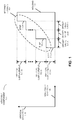
- FIG. 1 presents a block diagram illustrating an assembly component 100 that can be used to position and secure semiconductor dies (or chips) during assembly of a chip package (such as chip package 300 in FIGs. 3 and 4 , which is sometimes referred to as a 'ramp-stack chip package').
- This assembly component includes a housing 110 having a stepped terrace 112. Moreover, this stepped terrace includes a sequence of steps 114 in a vertical direction 116. Note that each step after step 114-1 is offset in a horizontal direction 118 by an associated one of offset values 120 from an immediately preceding step in the sequence of steps 114.
- offset values 120 may each have approximately a constant value for the sequence of steps 114 or may vary over the sequence of steps 114 ( i.e., the offset values for different steps 114 in stepped terrace 112 may be different).
- vertical displacements 122 associated with the sequence of steps 114 (other than those for step 114-1 or step 114- N ) may each have approximately a constant value or may vary over the sequence of steps 114 ( i.e., the vertical displacements for different steps 114 in stepped terrace 112 may be different).
- housing 110 may be configured to mate with a set of semiconductor dies 210 such that the set of semiconductor dies 210 are arranged in a stack 212 in vertical direction 116.
- vertical direction 116 is substantially perpendicular to semiconductor die 210-1 in stack 212 (and, thus, with horizontal direction 118).
- each semiconductor die, after semiconductor die 210-1 may be offset in horizontal direction 118 by an associated one of offset values 214 from an immediately preceding semiconductor die in stack 212, thereby defining a stepped terrace 216 at one side of stack 212.
- These offset values may have approximately a constant value for the set of semiconductor dies 210 or may vary over the set of semiconductor dies 210 ( i.e., the offset values for different steps in stepped terrace 216 may be different).
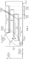
- assembly component 100 may facilitate assembly of chip package 300 in which: high-bandwidth ramp component 312 is rigidly mechanically and electrically coupled to semiconductor dies 210, thereby facilitating communication between semiconductor dies 210 and supplying power to semiconductor dies 210; ramp component 312 is positioned on the one side of stack 212 ( FIG. 2 ); and ramp component 312 is approximately parallel to a direction 314 (at angle 316) along stepped terrace 216 ( FIG. 2 ), which is between horizontal direction 118 and vertical direction 116.
- stepped terrace 112 may approximately be a mirror image of stepped terrace 216 ( FIG. 2 ).
- a given semiconductor die in the set of semiconductor dies 210 may have a nominal thickness 220, and a vertical displacement of a given step in sequence of steps 114 may be larger than nominal thickness 220 (or it may be larger than a maximum thickness of any of semiconductor dies 210).
- the thickness of at least some of semiconductor dies 210 in stack 212 may be different (for example, the thicknesses may vary over stack 212).
- vertical displacements 122 may each be 160 ⁇ m versus nominal thickness 220 of 150 ⁇ 5 ⁇ m. (However, in other embodiments thickness 220 may be between 30 and 250 ⁇ m.) This additional vertical displacement relative to thickness 220 may allow the adhesive in adhesive layers 222 to spread during assembly. Note that for nominal thickness 220 of 150 ⁇ m, angle 316 ( FIG. 3 ) may be between 15 and 20°. In general, nominal thickness 220 depends, in part, on the number of semiconductor dies 210 in stack 212. Furthermore, note that a nominal thickness 224 of adhesive layers 222 may be 10 ⁇ m. (However, in other embodiments the thickness of adhesive layers 222 may vary along vertical direction 116 in stack 212.)
- offset value at a given step in stepped terrace 112 may be the same or larger than the associated offset value in stepped terrace 216.
- offset values 120 ( FIG. 1 ) and offset values 214 may be determined based on direction 314 (or angle 316) in FIG. 3 and a nominal thickness of solder (such as solder ball 318 in FIG. 3 ) used to rigidly mechanically couple ramp component 312 ( FIG. 3 ) to set of semiconductor dies 210. Note that the thickness of the solder may be approximately constant over stack 212 or may vary over the stack ( i.e., along vertical direction 116).
- assembly component 100 facilitates assembly of the set of semiconductor dies 210 with an accumulated position error over the set of semiconductor dies 210 in vertical direction 116 (i.e., an accumulated position error in the vertical positions of semiconductor dies over stack 212) that is less than a sum of vertical errors associated with the set of semiconductor dies 210 and adhesive layers 222 (such as an epoxy or glue that cures in 10 s at 150 C) between the semiconductor dies 210.
- the accumulated position error may be associated with: thickness variation of the semiconductor dies 210, thickness variation of adhesive layers 222; and/or thickness variation of an optional heat-spreading material 226 (such as pressed graphite fibers) in at least some of adhesive layers 222.
- the accumulated position error may be less than 1 ⁇ m, and may be as small as 0 ⁇ m.
- assembly component 100 FIG. 1
- a maximum position error i.e., a maximum error in distance 320 in FIG. 3
- the maximum position error may be less than 1 ⁇ m, and may be as small as 0 ⁇ m.
- this may be accomplished by using a pick-and-place tool to assemble chip package 300 ( FIG.
- assembly component 100 in FIG. 1 includes mechanical stops, such as mechanical stops fabricated using polyimide, and semiconductor dies 210 may be pushed up against these mechanical stops during assembly of chip package 300 in FIG. 3 , thereby facilitating desired tolerances in horizontal direction 118 and/or vertical direction 116.
- the height and pitch of the solder bumps or pads may vary between at least some of semiconductor dies 210 along vertical direction 116.
- distance 320 i.e., the position of solder pad 322-1 relative to a center of a saw lane for semiconductor die 210-1
- solder pads 322 may each have an 80 ⁇ m width.
- the solder balls (such as solder ball 318) may have a diameter of 120 ⁇ m prior to reflowing or melting, and an approximate thickness between 40 and 60 ⁇ m after melting.
- two or more rows of solder balls may rigidly couple ramp component 312 to a given semiconductor die.
- FIG. 4 presents a block diagram illustrating a top view of assembled chip package 300 in which stack 212 ( FIG. 2 ) includes four semiconductor dies 210.
- This view of chip package 300 illustrates that in some embodiments solder pads 410 may have non-rectangular shapes.
- solder pads 410 may have oblong shapes, such as those that are 80 ⁇ m wide and 120 ⁇ m long. These solder-pad shapes on semiconductor dies 210 and/or ramp component 312 may tolerate some horizontal and/or vertical position errors.
- the solder pads can be moved to an edge of ramp component 312. This may facilitate a perpendicular orientation (i.e., angle 316 in FIG. 3 may be 0°).
- This configuration may facilitate a memory module in which contacts or pads associated with input/output ( I / O ) signal lines and power lines are at the edge of the ramp component (instead of down the 'spine'). In this way, a number of diffusion layers in the ramp component may be reduced. For example, there may be 60 contacts or pads along an edge of ramp component 312 in this memory module.
- assembly component 100 in FIG. 1 may facilitate highly accurate and high-yield assembly of chip package 300.
- this assembly component also facilitates the use of high-volume and low-cost manufacturing techniques, such as a pick-and-place tool, it can greatly reduce the cost of chip package 300.
- a ramp-stack chip package (such as chip package 300) is included in a dual in-line memory module.
- memory devices such as dynamic random access memory or another type of memory-storage device
- 72 memory devices (out of 80) may be used.
- this configuration may expose the full bandwidth of the memory devices in the memory module, such that there is little or no latency delay in accessing any of the memory devices.
- the dual in-line memory module may include multiple fields that each can include a ramp-stack chip package.
- one or more of these dual in-line memory modules may be coupled to a processor.
- the processor may be coupled to the one or more dual in-line memory modules using capacitive proximity communication ( PxC ) of capacitively coupled signals.
- the processor may be mounted on a substrate using C4 solder balls.
- FIG. 5 presents a flow diagram illustrating a method 500 for assembling a chip package using assembly component 100 ( FIG. 1 ).
- an edge of a first semiconductor die in a vertical stack of semiconductor dies is positioned proximate to a first step in a sequence of steps in a first stepped terrace in a vertical direction of a housing (operation 510), such as a housing in an assembly component.
- a housing such as a housing in an assembly component.
- the vertical direction is substantially perpendicular to the first semiconductor die.
- an adhesive layer is applied to a top surface of the first semiconductor die (operation 512).
- an edge of a second semiconductor die in the vertical stack of semiconductor dies is positioned proximate to a second step in the sequence of steps in the vertical direction of the housing, and a bottom surface of the second semiconductor die is mechanically coupled to the adhesive layer (operation 514).
- the second step is offset in a horizontal direction by a first offset value from the first step, and the second semiconductor die is offset in the horizontal direction by a second offset value, thereby defining a second stepped terrace at one side of the vertical stack.
- a ramp component is rigidly mechanically coupled to the first semiconductor die and the second semiconductor die (operation 516), where the ramp component is positioned on the one side of the vertical stack, and where the ramp component is approximately parallel to a direction along the second stepped terrace, which is between the horizontal direction and the vertical direction.
- positioning a given semiconductor die which can be one of the first semiconductor die and the second semiconductor die, may involve a pick-and-place tool.
- the horizontal and/or the vertical alignment is within 1-10 ⁇ m.
- this positioning may be based on optical alignment markers on the given semiconductor die.
- optical alignment markers may include fiducial markers.
- rigidly mechanically coupling the ramp component to the first semiconductor die and the second semiconductor die may involve melting solder on: the ramp component and/or the first semiconductor die and the second semiconductor die.
- the ramp component When reflowing the solder, the ramp component may be placed on the stack or vice versa. This may allow the weight of the ramp component (or the stack of semiconductor dies) to help overcome the surface tension of the solder.
- a compressive force may be applied in the vertical direction. This may ensure that the assembled chip package has a desired height. In some embodiments, a compressive force is applied along a normal to the ramp component. Either of these compressive forces may improve heat transfer within the stack, for example, by filling or reducing gaps between components in the chip package.
- chip package 300 ( FIGs. 3 and 4 ) is assembled without using assembly component 100 ( FIG. 1 ). This may be possible in chip packages that have a few semiconductor dies (or less) and which are, therefore, less sensitive to accumulated position errors.
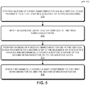
- FIG. 6 presents a flow diagram illustrating a method 600 for assembling the chip package without using assembly component 100 ( FIG. 1 ).
- the first semiconductor die is positioned in the vertical stack of semiconductor dies (operation 610), where the vertical stack is along the vertical direction that is substantially perpendicular to the first semiconductor die.
- the adhesive layer is applied to the top surface of the first semiconductor die (operation 612).
- the edge of the second semiconductor die in the vertical stack of semiconductor dies is positioned relative to the first semiconductor die (operation 614), where the bottom surface of the second semiconductor die is mechanically coupled to the adhesive layer, and where the second semiconductor die is offset in the horizontal direction by the offset value, thereby defining a stepped terrace at one side of the vertical stack.
- the ramp component is rigidly mechanically coupled to the first semiconductor die and the second semiconductor die (operation 616), where the ramp component is positioned on the one side of the vertical stack, and wherein the ramp component is approximately parallel to a direction along the stepped terrace, which is between the horizontal direction and the vertical direction.
- the stack may be assembled in pieces that include a subset of the semiconductor dies, which are subsequently combined into a full stack.
- the order of the operations may be changed, and/or two or more operations may be combined into a single operation.
- assembly component 100 may include fewer components or additional components.
- these devices and systems are illustrated as having a number of discrete items, these embodiments are intended to be functional descriptions of the various features that may be present rather than structural schematics of the embodiments described herein. Consequently, in these embodiments, two or more components may be combined into a single component and/or a position of one or more components may be changed.
- the semiconductor dies 210 may be fabricated using standard silicon processing. These semiconductor dies may provide silicon area that supports logic and/or memory functionality.
- ramp component 312 may be a passive component, such as a plastic substrate with metal traces to electrically couple to semiconductor dies 210.
- ramp component 312 may be fabricated using injection-molded plastic.
- ramp component 312 may be another semiconductor die with lithographically defined wires or signal lines.
- active devices such as limit amplifiers, may be included to reduce cross-talk between the signal lines. Additionally, cross-talk may be reduced in either an active or a passive ramp component 312 using differential signaling.
- ramp component 312 includes transistors and wires that shuttle data and power signals among semiconductor dies 210 via solder balls (such as solder ball 318).
- ramp component 312 may include high-voltage signals. These signals may be stepped down for use on semiconductor dies 210 using: a step-down regulator (such as a capacitor-to-capacitor step-down regulator), as well as capacitor and/or inductor discrete components to couple to semiconductor dies 210.
- ramp component 312 may include a buffer or logic chip for memory, and/or I / O connectors to external device(s) and/or system(s).
- the I / O connectors may include one or more: ball bonds, wire bonds, edge connectors and/or PxC connectors for coupling to external devices.
- these I / O connectors may be on a back surface of ramp component 312, and ramp component 312 may include one or more through-silicon vias ( TSV s) that couple the I / O connectors to solder pads, such as solder pad 322-2.
- TSV s through-silicon vias
- ramp component 312 and semiconductor dies 210 in chip package 300 are mounted on an optional substrate (such as a printed circuit board or a semiconductor die).
- This optional substrate may include: ball bonds, wire bonds, edge connectors and/or PxC connectors for coupling to external devices. If these I / O connectors are on a back surface of the optional substrate, the optional substrate may include one or more TSV s.
- solder balls are used in the preceding embodiments as an illustration of the electrical and mechanical coupling of ramp component 312 and semiconductor dies 210, in other embodiments these components may be electrically and/or mechanically coupled using other techniques, such as: microsprings, micro-spheres (in a ball-in-pit configuration described below), and/or an anisotropic film (such as an anisotropic elastomer film, which is sometimes referred to as an 'anisotropic conductive film').
- microsprings such as an anisotropic elastomer film, which is sometimes referred to as an 'anisotropic conductive film'.
- the PxC may include: communication of capacitively coupled signals (which is referred to as 'electrical proximity communication'), communication of optically coupled signals (which is referred to as 'optical proximity communication'), communication of electromagnetically coupled signals (which is referred to as 'electromagnetic proximity communication'), communication of inductively coupled signals, and/or communication of conductively coupled signals.
- the impedance of the resulting electrical contacts may be conductive and/or capacitive, i.e., may have a complex impedance that includes an in-phase component and/or an out-of-phase component.
- the impedance associated with the contacts is conductive, conventional transmit and receive I / O circuits may be used in components in chip package 300.
- the transmit and receive I / O circuits may include one or more embodiments described in U.S. patent application 12/425,871 , entitled "Receive Circuit for Connectors with Variable Complex Impedance," by Robert J. Drost et al., filed on April 17, 2009, US2010264954 ).
- the yield of chip package 300 may be increased by allowing rework (such as replacing a bad chip that is identified during assembly, testing or burn-in).
- remateable mechanical or electrical coupling should be understood to be mechanical or electrical coupling that can be established and broken repeatedly ( i.e., two or more times) without requiring rework or heating (such as with solder).
- the remateable mechanical or electrical coupling involves male and female components designed to couple to each other (such as components that snap together).
- FIG. 3 illustrates a particular configuration of chip package 300
- a number of techniques and configurations may be used to implement mechanical alignment and assembly with or without using assembly component 100 ( FIG. 1 ).
- semiconductor dies 210 and/or ramp component 312 may be positioned relative to each other using a ball-and-pit alignment technique (and, more generally, a positive-feature-in-negative-feature alignment technique).
- balls may be positioned into etch pits to relatively align components, such as semiconductor dies 210 in stack 212 ( FIG. 2 ).
- Other examples of positive features include hemisphere-shaped bumps.
- any combination of mechanically locking positive and negative surface features on components in chip package 300 may be used to align and/or assemble chip package 300.
- optional heat-spreading material 226 may help remove heat generated during operation of circuits on one or more semiconductor dies 210 and/or ramp component 312 ( FIGs. 3 and 4 ).
- This thermal management may include any of the following thermal paths: a first thermal path in a plane of semiconductor dies 210; a second thermal path in a plane of adhesive layers 222; and/or a third thermal path in a plane of optional heat-spreading material 226.
- the thermal flux associated with these thermal paths may be managed independently of each other via thermal coupling at an edge of the chip package.
- this thermal management may include the use of: phase change cooling, immersion cooling, and/or a cold plate. Also note that the thermal flux associated with the first thermal path that diffuses through the cross-sectional area at the edge of the chip package is a function of nominal thickness 220. Thus, the thermal management may be different in chip packages with larger or smaller nominal thicknesses of semiconductor dies 210.
- chip package 300 there may be optional encapsulation around at least a portion of chip package 300 ( FIGs. 3 and 4 ). Additionally, air gaps between components in chip package 300 ( FIGs. 3 and 4 ) may be underfilled to improve heat removal. This may be facilitated by decreasing angle 316 in FIG. 3 , i.e., semiconductor dies 210 may be tipped more toward vertical direction 116.
Landscapes
- Engineering & Computer Science (AREA)
- Microelectronics & Electronic Packaging (AREA)
- Power Engineering (AREA)
- Computer Hardware Design (AREA)
- Physics & Mathematics (AREA)
- Condensed Matter Physics & Semiconductors (AREA)
- General Physics & Mathematics (AREA)
- Manufacturing & Machinery (AREA)
- Wire Bonding (AREA)
- Die Bonding (AREA)
- Semiconductor Integrated Circuits (AREA)
- Led Device Packages (AREA)
Applications Claiming Priority (2)
| Application Number | Priority Date | Filing Date | Title |
|---|---|---|---|
| US12/873,945 US8373280B2 (en) | 2010-09-01 | 2010-09-01 | Manufacturing fixture for a ramp-stack chip package using solder for coupling a ramp component |
| PCT/US2011/046517 WO2012030469A2 (en) | 2010-09-01 | 2011-08-04 | Manufacturing fixture for a ramp-stack chip package |
Publications (2)
| Publication Number | Publication Date |
|---|---|
| EP2612355A2 EP2612355A2 (en) | 2013-07-10 |
| EP2612355B1 true EP2612355B1 (en) | 2021-06-30 |
Family
ID=44583404
Family Applications (1)
| Application Number | Title | Priority Date | Filing Date |
|---|---|---|---|
| EP11754564.0A Active EP2612355B1 (en) | 2010-09-01 | 2011-08-04 | Ramp-stack chip package and manufacture method thereof |
Country Status (7)
| Country | Link |
|---|---|
| US (1) | US8373280B2 (ja) |
| EP (1) | EP2612355B1 (ja) |
| JP (1) | JP6000951B2 (ja) |
| KR (1) | KR101807743B1 (ja) |
| CN (1) | CN103081103A (ja) |
| TW (1) | TWI517353B (ja) |
| WO (1) | WO2012030469A2 (ja) |
Families Citing this family (21)
| Publication number | Priority date | Publication date | Assignee | Title |
|---|---|---|---|---|
| US8390109B2 (en) * | 2011-02-17 | 2013-03-05 | Oracle America, Inc. | Chip package with plank stack of semiconductor dies |
| US8786080B2 (en) * | 2011-03-11 | 2014-07-22 | Altera Corporation | Systems including an I/O stack and methods for fabricating such systems |
| KR20130118175A (ko) * | 2012-04-19 | 2013-10-29 | 삼성전자주식회사 | 반도체 패키지 및 그의 제조 방법 |
| US9082632B2 (en) * | 2012-05-10 | 2015-07-14 | Oracle International Corporation | Ramp-stack chip package with variable chip spacing |
| KR102099878B1 (ko) | 2013-07-11 | 2020-04-10 | 삼성전자 주식회사 | 반도체 패키지 |
| WO2015032865A1 (en) * | 2013-09-05 | 2015-03-12 | Koninklijke Philips N.V. | Radiation detector element |
| BR122017018407B1 (pt) | 2013-09-27 | 2022-09-20 | Intel Corporation | Montagem de semicondutor e processo para produzir uma montagem de semicondutor |
| US9209165B2 (en) * | 2013-10-21 | 2015-12-08 | Oracle International Corporation | Technique for controlling positions of stacked dies |
| KR20160014475A (ko) * | 2014-07-29 | 2016-02-11 | 삼성전자주식회사 | 스택 패키지 |
| US9825002B2 (en) * | 2015-07-17 | 2017-11-21 | Invensas Corporation | Flipped die stack |
| US9871019B2 (en) | 2015-07-17 | 2018-01-16 | Invensas Corporation | Flipped die stack assemblies with leadframe interconnects |
| US9490195B1 (en) | 2015-07-17 | 2016-11-08 | Invensas Corporation | Wafer-level flipped die stacks with leadframes or metal foil interconnects |
| US9698093B2 (en) * | 2015-08-24 | 2017-07-04 | Nxp Usa,Inc. | Universal BGA substrate |
| US9508691B1 (en) | 2015-12-16 | 2016-11-29 | Invensas Corporation | Flipped die stacks with multiple rows of leadframe interconnects |
| WO2017111952A1 (en) * | 2015-12-22 | 2017-06-29 | Intel Corporation | Ultra small molded module integrated with die by module-on-wafer assembly |
| US10566310B2 (en) | 2016-04-11 | 2020-02-18 | Invensas Corporation | Microelectronic packages having stacked die and wire bond interconnects |
| US9595511B1 (en) | 2016-05-12 | 2017-03-14 | Invensas Corporation | Microelectronic packages and assemblies with improved flyby signaling operation |
| US9728524B1 (en) | 2016-06-30 | 2017-08-08 | Invensas Corporation | Enhanced density assembly having microelectronic packages mounted at substantial angle to board |
| US20190279962A1 (en) * | 2018-03-09 | 2019-09-12 | Oracle International Corporation | Method and apparatus for stacking warped chips to assemble three-dimensional integrated circuits |
| CN111048479B (zh) * | 2019-12-27 | 2021-06-29 | 华天科技(南京)有限公司 | 一种多芯片堆叠封装结构及其封装方法 |
| CN111554682B (zh) * | 2020-05-18 | 2023-03-21 | 中国科学院微电子研究所 | 一种半导体器件及其制作方法 |
Citations (2)
| Publication number | Priority date | Publication date | Assignee | Title |
|---|---|---|---|---|
| JP2009027068A (ja) * | 2007-07-23 | 2009-02-05 | Alps Electric Co Ltd | 半導体装置 |
| TW201025532A (en) * | 2008-12-16 | 2010-07-01 | Powertech Technology Inc | Chip stacked package having single-sided pads on chips |
Family Cites Families (24)
| Publication number | Priority date | Publication date | Assignee | Title |
|---|---|---|---|---|
| US5239447A (en) * | 1991-09-13 | 1993-08-24 | International Business Machines Corporation | Stepped electronic device package |
| DK174111B1 (da) | 1998-01-26 | 2002-06-24 | Giga As | Elektrisk forbindelseselement samt fremgangsmåde til fremstilling af et sådant |
| TW460927B (en) | 1999-01-18 | 2001-10-21 | Toshiba Corp | Semiconductor device, mounting method for semiconductor device and manufacturing method for semiconductor device |
| US6873361B1 (en) * | 1999-01-28 | 2005-03-29 | Takeharu Etoh | Image sensor having a plurality of chips |
| JP2001036309A (ja) | 1999-07-15 | 2001-02-09 | Nec Eng Ltd | マルチチップモジュール接続構造 |
| US6376904B1 (en) * | 1999-12-23 | 2002-04-23 | Rambus Inc. | Redistributed bond pads in stacked integrated circuit die package |
| JP2004228117A (ja) * | 2003-01-20 | 2004-08-12 | Idea System Kk | 半導体装置および半導体パッケージ |
| KR20050117715A (ko) * | 2004-06-11 | 2005-12-15 | 삼성전자주식회사 | 반도체 패키지 및 그 제조방법 |
| US7832818B1 (en) * | 2005-05-03 | 2010-11-16 | Oracle America, Inc. | Inkjet pen with proximity interconnect |
| JP4726640B2 (ja) * | 2006-01-20 | 2011-07-20 | ルネサスエレクトロニクス株式会社 | 半導体装置 |
| US7420269B2 (en) * | 2006-04-18 | 2008-09-02 | Stats Chippac Ltd. | Stacked integrated circuit package-in-package system |
| TWI357640B (en) * | 2007-01-24 | 2012-02-01 | Siliconware Precision Industries Co Ltd | Multichip stacking structure and fabricating metho |
| US8723332B2 (en) * | 2007-06-11 | 2014-05-13 | Invensas Corporation | Electrically interconnected stacked die assemblies |
| JP2009027067A (ja) * | 2007-07-23 | 2009-02-05 | Alps Electric Co Ltd | 半導体装置の製造方法および半導体装置 |
| JP4317245B2 (ja) * | 2007-09-27 | 2009-08-19 | 新光電気工業株式会社 | 電子装置及びその製造方法 |
| JP4498403B2 (ja) * | 2007-09-28 | 2010-07-07 | 株式会社東芝 | 半導体装置と半導体記憶装置 |
| KR20090093398A (ko) * | 2008-02-29 | 2009-09-02 | 주식회사 하이닉스반도체 | 스택 패키지 |
| KR100997787B1 (ko) | 2008-06-30 | 2010-12-02 | 주식회사 하이닉스반도체 | 적층 반도체 패키지 및 이의 제조 방법 |
| TWM352775U (en) * | 2008-10-27 | 2009-03-11 | Kun Yuan Technology Co Ltd | Staggered-stacking structure of chip |
| US20100193930A1 (en) * | 2009-02-02 | 2010-08-05 | Samsung Electronics Co., Ltd. | Multi-chip semiconductor devices having conductive vias and methods of forming the same |
| US8476749B2 (en) * | 2009-07-22 | 2013-07-02 | Oracle America, Inc. | High-bandwidth ramp-stack chip package |
| JP2011061112A (ja) * | 2009-09-14 | 2011-03-24 | Shinko Electric Ind Co Ltd | 半導体チップ積層体及び製造方法 |
| US20110200976A1 (en) * | 2010-02-12 | 2011-08-18 | Mari Hou | Method and apparatus for in vitro testing for medical devices |
| US8290319B2 (en) * | 2010-08-25 | 2012-10-16 | Oracle America, Inc. | Optical communication in a ramp-stack chip package |
-
2010
- 2010-09-01 US US12/873,945 patent/US8373280B2/en active Active
-
2011
- 2011-08-04 JP JP2013527082A patent/JP6000951B2/ja active Active
- 2011-08-04 WO PCT/US2011/046517 patent/WO2012030469A2/en active Application Filing
- 2011-08-04 KR KR1020137005216A patent/KR101807743B1/ko active IP Right Grant
- 2011-08-04 EP EP11754564.0A patent/EP2612355B1/en active Active
- 2011-08-04 CN CN2011800421931A patent/CN103081103A/zh active Pending
- 2011-08-11 TW TW100128698A patent/TWI517353B/zh active
Patent Citations (3)
| Publication number | Priority date | Publication date | Assignee | Title |
|---|---|---|---|---|
| JP2009027068A (ja) * | 2007-07-23 | 2009-02-05 | Alps Electric Co Ltd | 半導体装置 |
| TW201025532A (en) * | 2008-12-16 | 2010-07-01 | Powertech Technology Inc | Chip stacked package having single-sided pads on chips |
| TWI378545B (en) * | 2008-12-16 | 2012-12-01 | Powertech Technology Inc | Chip stacked package having single-sided pads on chips |
Also Published As
| Publication number | Publication date |
|---|---|
| US20120049376A1 (en) | 2012-03-01 |
| EP2612355A2 (en) | 2013-07-10 |
| KR20130105819A (ko) | 2013-09-26 |
| TW201220464A (en) | 2012-05-16 |
| TWI517353B (zh) | 2016-01-11 |
| JP2013536998A (ja) | 2013-09-26 |
| US8373280B2 (en) | 2013-02-12 |
| WO2012030469A2 (en) | 2012-03-08 |
| CN103081103A (zh) | 2013-05-01 |
| KR101807743B1 (ko) | 2017-12-13 |
| JP6000951B2 (ja) | 2016-10-05 |
| WO2012030469A3 (en) | 2012-05-10 |
Similar Documents
| Publication | Publication Date | Title |
|---|---|---|
| EP2612355B1 (en) | Ramp-stack chip package and manufacture method thereof | |
| EP2612356B1 (en) | Ramp-stack chip package with static bends | |
| EP2609623B1 (en) | Optical communication in a ramp-stack chip package | |
| US8772920B2 (en) | Interconnection and assembly of three-dimensional chip packages | |
| US8390109B2 (en) | Chip package with plank stack of semiconductor dies | |
| KR102174120B1 (ko) | 스택되는 다이들의 위치들을 제어하는 기술 | |
| US8476749B2 (en) | High-bandwidth ramp-stack chip package | |
| US20130299977A1 (en) | Ramp-stack chip package with variable chip spacing | |
| US20240321840A1 (en) | Three-dimensional semiconductor package | |
| CN112510032A (zh) | 芯片堆叠结构及其制造方法 |
Legal Events
| Date | Code | Title | Description |
|---|---|---|---|
| PUAI | Public reference made under article 153(3) epc to a published international application that has entered the european phase |
Free format text: ORIGINAL CODE: 0009012 |
|
| 17P | Request for examination filed |
Effective date: 20130207 |
|
| AK | Designated contracting states |
Kind code of ref document: A2 Designated state(s): AL AT BE BG CH CY CZ DE DK EE ES FI FR GB GR HR HU IE IS IT LI LT LU LV MC MK MT NL NO PL PT RO RS SE SI SK SM TR |
|
| DAX | Request for extension of the european patent (deleted) | ||
| STAA | Information on the status of an ep patent application or granted ep patent |
Free format text: STATUS: EXAMINATION IS IN PROGRESS |
|
| 17Q | First examination report despatched |
Effective date: 20190131 |
|
| RIC1 | Information provided on ipc code assigned before grant |
Ipc: H01L 25/065 20060101ALI20191210BHEP Ipc: H01L 23/42 20060101ALI20191210BHEP Ipc: H01L 23/00 20060101ALI20191210BHEP Ipc: H01L 21/50 20060101ALI20191210BHEP Ipc: H01L 23/498 20060101AFI20191210BHEP Ipc: H01L 25/00 20060101ALI20191210BHEP |
|
| GRAJ | Information related to disapproval of communication of intention to grant by the applicant or resumption of examination proceedings by the epo deleted |
Free format text: ORIGINAL CODE: EPIDOSDIGR1 |
|
| GRAP | Despatch of communication of intention to grant a patent |
Free format text: ORIGINAL CODE: EPIDOSNIGR1 |
|
| GRAP | Despatch of communication of intention to grant a patent |
Free format text: ORIGINAL CODE: EPIDOSNIGR1 |
|
| STAA | Information on the status of an ep patent application or granted ep patent |
Free format text: STATUS: GRANT OF PATENT IS INTENDED |
|
| INTG | Intention to grant announced |
Effective date: 20200203 |
|
| GRAJ | Information related to disapproval of communication of intention to grant by the applicant or resumption of examination proceedings by the epo deleted |
Free format text: ORIGINAL CODE: EPIDOSDIGR1 |
|
| STAA | Information on the status of an ep patent application or granted ep patent |
Free format text: STATUS: EXAMINATION IS IN PROGRESS |
|
| INTC | Intention to grant announced (deleted) | ||
| GRAP | Despatch of communication of intention to grant a patent |
Free format text: ORIGINAL CODE: EPIDOSNIGR1 |
|
| STAA | Information on the status of an ep patent application or granted ep patent |
Free format text: STATUS: GRANT OF PATENT IS INTENDED |
|
| INTG | Intention to grant announced |
Effective date: 20201118 |
|
| GRAJ | Information related to disapproval of communication of intention to grant by the applicant or resumption of examination proceedings by the epo deleted |
Free format text: ORIGINAL CODE: EPIDOSDIGR1 |
|
| STAA | Information on the status of an ep patent application or granted ep patent |
Free format text: STATUS: EXAMINATION IS IN PROGRESS |
|
| GRAS | Grant fee paid |
Free format text: ORIGINAL CODE: EPIDOSNIGR3 |
|
| STAA | Information on the status of an ep patent application or granted ep patent |
Free format text: STATUS: GRANT OF PATENT IS INTENDED |
|
| GRAP | Despatch of communication of intention to grant a patent |
Free format text: ORIGINAL CODE: EPIDOSNIGR1 |
|
| INTC | Intention to grant announced (deleted) | ||
| INTG | Intention to grant announced |
Effective date: 20210323 |
|
| GRAA | (expected) grant |
Free format text: ORIGINAL CODE: 0009210 |
|
| STAA | Information on the status of an ep patent application or granted ep patent |
Free format text: STATUS: THE PATENT HAS BEEN GRANTED |
|
| AK | Designated contracting states |
Kind code of ref document: B1 Designated state(s): AL AT BE BG CH CY CZ DE DK EE ES FI FR GB GR HR HU IE IS IT LI LT LU LV MC MK MT NL NO PL PT RO RS SE SI SK SM TR |
|
| REG | Reference to a national code |
Ref country code: GB Ref legal event code: FG4D Ref country code: CH Ref legal event code: EP |
|
| REG | Reference to a national code |
Ref country code: DE Ref legal event code: R096 Ref document number: 602011071278 Country of ref document: DE Ref country code: AT Ref legal event code: REF Ref document number: 1407141 Country of ref document: AT Kind code of ref document: T Effective date: 20210715 |
|
| REG | Reference to a national code |
Ref country code: IE Ref legal event code: FG4D |
|
| REG | Reference to a national code |
Ref country code: LT Ref legal event code: MG9D |
|
| PG25 | Lapsed in a contracting state [announced via postgrant information from national office to epo] |
Ref country code: FI Free format text: LAPSE BECAUSE OF FAILURE TO SUBMIT A TRANSLATION OF THE DESCRIPTION OR TO PAY THE FEE WITHIN THE PRESCRIBED TIME-LIMIT Effective date: 20210630 Ref country code: HR Free format text: LAPSE BECAUSE OF FAILURE TO SUBMIT A TRANSLATION OF THE DESCRIPTION OR TO PAY THE FEE WITHIN THE PRESCRIBED TIME-LIMIT Effective date: 20210630 Ref country code: BG Free format text: LAPSE BECAUSE OF FAILURE TO SUBMIT A TRANSLATION OF THE DESCRIPTION OR TO PAY THE FEE WITHIN THE PRESCRIBED TIME-LIMIT Effective date: 20210930 |
|
| REG | Reference to a national code |
Ref country code: NL Ref legal event code: MP Effective date: 20210630 |
|
| REG | Reference to a national code |
Ref country code: AT Ref legal event code: MK05 Ref document number: 1407141 Country of ref document: AT Kind code of ref document: T Effective date: 20210630 |
|
| PG25 | Lapsed in a contracting state [announced via postgrant information from national office to epo] |
Ref country code: NO Free format text: LAPSE BECAUSE OF FAILURE TO SUBMIT A TRANSLATION OF THE DESCRIPTION OR TO PAY THE FEE WITHIN THE PRESCRIBED TIME-LIMIT Effective date: 20210930 Ref country code: SE Free format text: LAPSE BECAUSE OF FAILURE TO SUBMIT A TRANSLATION OF THE DESCRIPTION OR TO PAY THE FEE WITHIN THE PRESCRIBED TIME-LIMIT Effective date: 20210630 Ref country code: RS Free format text: LAPSE BECAUSE OF FAILURE TO SUBMIT A TRANSLATION OF THE DESCRIPTION OR TO PAY THE FEE WITHIN THE PRESCRIBED TIME-LIMIT Effective date: 20210630 Ref country code: GR Free format text: LAPSE BECAUSE OF FAILURE TO SUBMIT A TRANSLATION OF THE DESCRIPTION OR TO PAY THE FEE WITHIN THE PRESCRIBED TIME-LIMIT Effective date: 20211001 Ref country code: LV Free format text: LAPSE BECAUSE OF FAILURE TO SUBMIT A TRANSLATION OF THE DESCRIPTION OR TO PAY THE FEE WITHIN THE PRESCRIBED TIME-LIMIT Effective date: 20210630 |
|
| PG25 | Lapsed in a contracting state [announced via postgrant information from national office to epo] |
Ref country code: SM Free format text: LAPSE BECAUSE OF FAILURE TO SUBMIT A TRANSLATION OF THE DESCRIPTION OR TO PAY THE FEE WITHIN THE PRESCRIBED TIME-LIMIT Effective date: 20210630 Ref country code: SK Free format text: LAPSE BECAUSE OF FAILURE TO SUBMIT A TRANSLATION OF THE DESCRIPTION OR TO PAY THE FEE WITHIN THE PRESCRIBED TIME-LIMIT Effective date: 20210630 Ref country code: EE Free format text: LAPSE BECAUSE OF FAILURE TO SUBMIT A TRANSLATION OF THE DESCRIPTION OR TO PAY THE FEE WITHIN THE PRESCRIBED TIME-LIMIT Effective date: 20210630 Ref country code: CZ Free format text: LAPSE BECAUSE OF FAILURE TO SUBMIT A TRANSLATION OF THE DESCRIPTION OR TO PAY THE FEE WITHIN THE PRESCRIBED TIME-LIMIT Effective date: 20210630 Ref country code: AT Free format text: LAPSE BECAUSE OF FAILURE TO SUBMIT A TRANSLATION OF THE DESCRIPTION OR TO PAY THE FEE WITHIN THE PRESCRIBED TIME-LIMIT Effective date: 20210630 Ref country code: RO Free format text: LAPSE BECAUSE OF FAILURE TO SUBMIT A TRANSLATION OF THE DESCRIPTION OR TO PAY THE FEE WITHIN THE PRESCRIBED TIME-LIMIT Effective date: 20210630 Ref country code: NL Free format text: LAPSE BECAUSE OF FAILURE TO SUBMIT A TRANSLATION OF THE DESCRIPTION OR TO PAY THE FEE WITHIN THE PRESCRIBED TIME-LIMIT Effective date: 20210630 Ref country code: PT Free format text: LAPSE BECAUSE OF FAILURE TO SUBMIT A TRANSLATION OF THE DESCRIPTION OR TO PAY THE FEE WITHIN THE PRESCRIBED TIME-LIMIT Effective date: 20211102 Ref country code: ES Free format text: LAPSE BECAUSE OF FAILURE TO SUBMIT A TRANSLATION OF THE DESCRIPTION OR TO PAY THE FEE WITHIN THE PRESCRIBED TIME-LIMIT Effective date: 20210630 |
|
| PG25 | Lapsed in a contracting state [announced via postgrant information from national office to epo] |
Ref country code: PL Free format text: LAPSE BECAUSE OF FAILURE TO SUBMIT A TRANSLATION OF THE DESCRIPTION OR TO PAY THE FEE WITHIN THE PRESCRIBED TIME-LIMIT Effective date: 20210630 |
|
| REG | Reference to a national code |
Ref country code: DE Ref legal event code: R097 Ref document number: 602011071278 Country of ref document: DE Ref country code: CH Ref legal event code: PL |
|
| PG25 | Lapsed in a contracting state [announced via postgrant information from national office to epo] |
Ref country code: MC Free format text: LAPSE BECAUSE OF FAILURE TO SUBMIT A TRANSLATION OF THE DESCRIPTION OR TO PAY THE FEE WITHIN THE PRESCRIBED TIME-LIMIT Effective date: 20210630 |
|
| REG | Reference to a national code |
Ref country code: BE Ref legal event code: MM Effective date: 20210831 |
|
| PG25 | Lapsed in a contracting state [announced via postgrant information from national office to epo] |
Ref country code: LI Free format text: LAPSE BECAUSE OF NON-PAYMENT OF DUE FEES Effective date: 20210831 Ref country code: DK Free format text: LAPSE BECAUSE OF FAILURE TO SUBMIT A TRANSLATION OF THE DESCRIPTION OR TO PAY THE FEE WITHIN THE PRESCRIBED TIME-LIMIT Effective date: 20210630 Ref country code: CH Free format text: LAPSE BECAUSE OF NON-PAYMENT OF DUE FEES Effective date: 20210831 |
|
| PLBE | No opposition filed within time limit |
Free format text: ORIGINAL CODE: 0009261 |
|
| STAA | Information on the status of an ep patent application or granted ep patent |
Free format text: STATUS: NO OPPOSITION FILED WITHIN TIME LIMIT |
|
| PG25 | Lapsed in a contracting state [announced via postgrant information from national office to epo] |
Ref country code: LU Free format text: LAPSE BECAUSE OF NON-PAYMENT OF DUE FEES Effective date: 20210804 Ref country code: AL Free format text: LAPSE BECAUSE OF FAILURE TO SUBMIT A TRANSLATION OF THE DESCRIPTION OR TO PAY THE FEE WITHIN THE PRESCRIBED TIME-LIMIT Effective date: 20210630 |
|
| 26N | No opposition filed |
Effective date: 20220331 |
|
| PG25 | Lapsed in a contracting state [announced via postgrant information from national office to epo] |
Ref country code: IT Free format text: LAPSE BECAUSE OF FAILURE TO SUBMIT A TRANSLATION OF THE DESCRIPTION OR TO PAY THE FEE WITHIN THE PRESCRIBED TIME-LIMIT Effective date: 20210630 Ref country code: IE Free format text: LAPSE BECAUSE OF NON-PAYMENT OF DUE FEES Effective date: 20210804 Ref country code: FR Free format text: LAPSE BECAUSE OF NON-PAYMENT OF DUE FEES Effective date: 20210830 Ref country code: BE Free format text: LAPSE BECAUSE OF NON-PAYMENT OF DUE FEES Effective date: 20210831 |
|
| PG25 | Lapsed in a contracting state [announced via postgrant information from national office to epo] |
Ref country code: LT Free format text: LAPSE BECAUSE OF FAILURE TO SUBMIT A TRANSLATION OF THE DESCRIPTION OR TO PAY THE FEE WITHIN THE PRESCRIBED TIME-LIMIT Effective date: 20210630 |
|
| PG25 | Lapsed in a contracting state [announced via postgrant information from national office to epo] |
Ref country code: HU Free format text: LAPSE BECAUSE OF FAILURE TO SUBMIT A TRANSLATION OF THE DESCRIPTION OR TO PAY THE FEE WITHIN THE PRESCRIBED TIME-LIMIT; INVALID AB INITIO Effective date: 20110804 Ref country code: CY Free format text: LAPSE BECAUSE OF FAILURE TO SUBMIT A TRANSLATION OF THE DESCRIPTION OR TO PAY THE FEE WITHIN THE PRESCRIBED TIME-LIMIT Effective date: 20210630 |
|
| P01 | Opt-out of the competence of the unified patent court (upc) registered |
Effective date: 20230522 |
|
| PGFP | Annual fee paid to national office [announced via postgrant information from national office to epo] |
Ref country code: GB Payment date: 20230629 Year of fee payment: 13 |
|
| PGFP | Annual fee paid to national office [announced via postgrant information from national office to epo] |
Ref country code: DE Payment date: 20230703 Year of fee payment: 13 |
|
| PG25 | Lapsed in a contracting state [announced via postgrant information from national office to epo] |
Ref country code: MK Free format text: LAPSE BECAUSE OF FAILURE TO SUBMIT A TRANSLATION OF THE DESCRIPTION OR TO PAY THE FEE WITHIN THE PRESCRIBED TIME-LIMIT Effective date: 20210630 |
|
| PG25 | Lapsed in a contracting state [announced via postgrant information from national office to epo] |
Ref country code: TR Free format text: LAPSE BECAUSE OF FAILURE TO SUBMIT A TRANSLATION OF THE DESCRIPTION OR TO PAY THE FEE WITHIN THE PRESCRIBED TIME-LIMIT Effective date: 20210630 |