EP2610560A1 - Système d'alimentation en eau chaude du type à réservoir d'eau chaude et procédé d'exploitation de celui-ci - Google Patents
Système d'alimentation en eau chaude du type à réservoir d'eau chaude et procédé d'exploitation de celui-ci Download PDFInfo
- Publication number
- EP2610560A1 EP2610560A1 EP20110799599 EP11799599A EP2610560A1 EP 2610560 A1 EP2610560 A1 EP 2610560A1 EP 20110799599 EP20110799599 EP 20110799599 EP 11799599 A EP11799599 A EP 11799599A EP 2610560 A1 EP2610560 A1 EP 2610560A1
- Authority
- EP
- European Patent Office
- Prior art keywords
- refrigerant
- heat exchanger
- temperature
- path
- water
- Prior art date
- Legal status (The legal status is an assumption and is not a legal conclusion. Google has not performed a legal analysis and makes no representation as to the accuracy of the status listed.)
- Granted
Links
- XLYOFNOQVPJJNP-UHFFFAOYSA-N water Substances O XLYOFNOQVPJJNP-UHFFFAOYSA-N 0.000 title claims abstract description 220
- 238000000034 method Methods 0.000 title claims description 12
- 239000003507 refrigerant Substances 0.000 claims abstract description 129
- 238000001816 cooling Methods 0.000 claims description 5
- 239000008236 heating water Substances 0.000 claims 4
- 230000007423 decrease Effects 0.000 description 6
- QGZKDVFQNNGYKY-UHFFFAOYSA-N Ammonia Chemical compound N QGZKDVFQNNGYKY-UHFFFAOYSA-N 0.000 description 4
- 230000015556 catabolic process Effects 0.000 description 3
- 238000006731 degradation reaction Methods 0.000 description 3
- 239000004215 Carbon black (E152) Substances 0.000 description 2
- 229910021529 ammonia Inorganic materials 0.000 description 2
- KYKAJFCTULSVSH-UHFFFAOYSA-N chloro(fluoro)methane Chemical compound F[C]Cl KYKAJFCTULSVSH-UHFFFAOYSA-N 0.000 description 2
- 230000003247 decreasing effect Effects 0.000 description 2
- 239000007789 gas Substances 0.000 description 2
- 238000010438 heat treatment Methods 0.000 description 2
- 229930195733 hydrocarbon Natural products 0.000 description 2
- 150000002430 hydrocarbons Chemical class 0.000 description 2
- 239000007788 liquid Substances 0.000 description 2
- 238000005259 measurement Methods 0.000 description 2
- HBBGRARXTFLTSG-UHFFFAOYSA-N Lithium ion Chemical compound [Li+] HBBGRARXTFLTSG-UHFFFAOYSA-N 0.000 description 1
- 230000002411 adverse Effects 0.000 description 1
- 239000003570 air Substances 0.000 description 1
- 239000003990 capacitor Substances 0.000 description 1
- 239000000446 fuel Substances 0.000 description 1
- 229910001416 lithium ion Inorganic materials 0.000 description 1
- 238000011144 upstream manufacturing Methods 0.000 description 1
Images


Classifications
-
- H—ELECTRICITY
- H01—ELECTRIC ELEMENTS
- H01M—PROCESSES OR MEANS, e.g. BATTERIES, FOR THE DIRECT CONVERSION OF CHEMICAL ENERGY INTO ELECTRICAL ENERGY
- H01M10/00—Secondary cells; Manufacture thereof
- H01M10/42—Methods or arrangements for servicing or maintenance of secondary cells or secondary half-cells
- H01M10/48—Accumulators combined with arrangements for measuring, testing or indicating the condition of cells, e.g. the level or density of the electrolyte
- H01M10/486—Accumulators combined with arrangements for measuring, testing or indicating the condition of cells, e.g. the level or density of the electrolyte for measuring temperature
-
- F—MECHANICAL ENGINEERING; LIGHTING; HEATING; WEAPONS; BLASTING
- F24—HEATING; RANGES; VENTILATING
- F24D—DOMESTIC- OR SPACE-HEATING SYSTEMS, e.g. CENTRAL HEATING SYSTEMS; DOMESTIC HOT-WATER SUPPLY SYSTEMS; ELEMENTS OR COMPONENTS THEREFOR
- F24D11/00—Central heating systems using heat accumulated in storage masses
- F24D11/02—Central heating systems using heat accumulated in storage masses using heat pumps
- F24D11/0214—Central heating systems using heat accumulated in storage masses using heat pumps water heating system
- F24D11/0235—Central heating systems using heat accumulated in storage masses using heat pumps water heating system with recuperation of waste energy
-
- F—MECHANICAL ENGINEERING; LIGHTING; HEATING; WEAPONS; BLASTING
- F24—HEATING; RANGES; VENTILATING
- F24D—DOMESTIC- OR SPACE-HEATING SYSTEMS, e.g. CENTRAL HEATING SYSTEMS; DOMESTIC HOT-WATER SUPPLY SYSTEMS; ELEMENTS OR COMPONENTS THEREFOR
- F24D19/00—Details
- F24D19/10—Arrangement or mounting of control or safety devices
- F24D19/1006—Arrangement or mounting of control or safety devices for water heating systems
- F24D19/1066—Arrangement or mounting of control or safety devices for water heating systems for the combination of central heating and domestic hot water
- F24D19/1072—Arrangement or mounting of control or safety devices for water heating systems for the combination of central heating and domestic hot water the system uses a heat pump
-
- F—MECHANICAL ENGINEERING; LIGHTING; HEATING; WEAPONS; BLASTING
- F24—HEATING; RANGES; VENTILATING
- F24D—DOMESTIC- OR SPACE-HEATING SYSTEMS, e.g. CENTRAL HEATING SYSTEMS; DOMESTIC HOT-WATER SUPPLY SYSTEMS; ELEMENTS OR COMPONENTS THEREFOR
- F24D3/00—Hot-water central heating systems
- F24D3/08—Hot-water central heating systems in combination with systems for domestic hot-water supply
-
- H—ELECTRICITY
- H01—ELECTRIC ELEMENTS
- H01M—PROCESSES OR MEANS, e.g. BATTERIES, FOR THE DIRECT CONVERSION OF CHEMICAL ENERGY INTO ELECTRICAL ENERGY
- H01M10/00—Secondary cells; Manufacture thereof
- H01M10/60—Heating or cooling; Temperature control
- H01M10/61—Types of temperature control
- H01M10/613—Cooling or keeping cold
-
- H—ELECTRICITY
- H01—ELECTRIC ELEMENTS
- H01M—PROCESSES OR MEANS, e.g. BATTERIES, FOR THE DIRECT CONVERSION OF CHEMICAL ENERGY INTO ELECTRICAL ENERGY
- H01M10/00—Secondary cells; Manufacture thereof
- H01M10/60—Heating or cooling; Temperature control
- H01M10/63—Control systems
- H01M10/633—Control systems characterised by algorithms, flow charts, software details or the like
-
- H—ELECTRICITY
- H01—ELECTRIC ELEMENTS
- H01M—PROCESSES OR MEANS, e.g. BATTERIES, FOR THE DIRECT CONVERSION OF CHEMICAL ENERGY INTO ELECTRICAL ENERGY
- H01M10/00—Secondary cells; Manufacture thereof
- H01M10/60—Heating or cooling; Temperature control
- H01M10/65—Means for temperature control structurally associated with the cells
- H01M10/656—Means for temperature control structurally associated with the cells characterised by the type of heat-exchange fluid
-
- H—ELECTRICITY
- H01—ELECTRIC ELEMENTS
- H01M—PROCESSES OR MEANS, e.g. BATTERIES, FOR THE DIRECT CONVERSION OF CHEMICAL ENERGY INTO ELECTRICAL ENERGY
- H01M10/00—Secondary cells; Manufacture thereof
- H01M10/60—Heating or cooling; Temperature control
- H01M10/65—Means for temperature control structurally associated with the cells
- H01M10/657—Means for temperature control structurally associated with the cells by electric or electromagnetic means
- H01M10/6571—Resistive heaters
-
- H—ELECTRICITY
- H01—ELECTRIC ELEMENTS
- H01M—PROCESSES OR MEANS, e.g. BATTERIES, FOR THE DIRECT CONVERSION OF CHEMICAL ENERGY INTO ELECTRICAL ENERGY
- H01M10/00—Secondary cells; Manufacture thereof
- H01M10/60—Heating or cooling; Temperature control
- H01M10/65—Means for temperature control structurally associated with the cells
- H01M10/659—Means for temperature control structurally associated with the cells by heat storage or buffering, e.g. heat capacity or liquid-solid phase changes or transition
-
- F—MECHANICAL ENGINEERING; LIGHTING; HEATING; WEAPONS; BLASTING
- F24—HEATING; RANGES; VENTILATING
- F24D—DOMESTIC- OR SPACE-HEATING SYSTEMS, e.g. CENTRAL HEATING SYSTEMS; DOMESTIC HOT-WATER SUPPLY SYSTEMS; ELEMENTS OR COMPONENTS THEREFOR
- F24D18/00—Small-scale combined heat and power [CHP] generation systems specially adapted for domestic heating, space heating or domestic hot-water supply
-
- F—MECHANICAL ENGINEERING; LIGHTING; HEATING; WEAPONS; BLASTING
- F24—HEATING; RANGES; VENTILATING
- F24D—DOMESTIC- OR SPACE-HEATING SYSTEMS, e.g. CENTRAL HEATING SYSTEMS; DOMESTIC HOT-WATER SUPPLY SYSTEMS; ELEMENTS OR COMPONENTS THEREFOR
- F24D2101/00—Electric generators of small-scale CHP systems
-
- F—MECHANICAL ENGINEERING; LIGHTING; HEATING; WEAPONS; BLASTING
- F24—HEATING; RANGES; VENTILATING
- F24D—DOMESTIC- OR SPACE-HEATING SYSTEMS, e.g. CENTRAL HEATING SYSTEMS; DOMESTIC HOT-WATER SUPPLY SYSTEMS; ELEMENTS OR COMPONENTS THEREFOR
- F24D2103/00—Thermal aspects of small-scale CHP systems
- F24D2103/10—Small-scale CHP systems characterised by their heat recovery units
- F24D2103/13—Small-scale CHP systems characterised by their heat recovery units characterised by their heat exchangers
-
- F—MECHANICAL ENGINEERING; LIGHTING; HEATING; WEAPONS; BLASTING
- F24—HEATING; RANGES; VENTILATING
- F24D—DOMESTIC- OR SPACE-HEATING SYSTEMS, e.g. CENTRAL HEATING SYSTEMS; DOMESTIC HOT-WATER SUPPLY SYSTEMS; ELEMENTS OR COMPONENTS THEREFOR
- F24D2200/00—Heat sources or energy sources
- F24D2200/12—Heat pump
- F24D2200/123—Compression type heat pumps
-
- F—MECHANICAL ENGINEERING; LIGHTING; HEATING; WEAPONS; BLASTING
- F24—HEATING; RANGES; VENTILATING
- F24D—DOMESTIC- OR SPACE-HEATING SYSTEMS, e.g. CENTRAL HEATING SYSTEMS; DOMESTIC HOT-WATER SUPPLY SYSTEMS; ELEMENTS OR COMPONENTS THEREFOR
- F24D2200/00—Heat sources or energy sources
- F24D2200/16—Waste heat
- F24D2200/29—Electrical devices, e.g. computers, servers
-
- F—MECHANICAL ENGINEERING; LIGHTING; HEATING; WEAPONS; BLASTING
- F24—HEATING; RANGES; VENTILATING
- F24H—FLUID HEATERS, e.g. WATER OR AIR HEATERS, HAVING HEAT-GENERATING MEANS, e.g. HEAT PUMPS, IN GENERAL
- F24H2240/00—Fluid heaters having electrical generators
- F24H2240/01—Batteries, electrical energy storage device
-
- Y—GENERAL TAGGING OF NEW TECHNOLOGICAL DEVELOPMENTS; GENERAL TAGGING OF CROSS-SECTIONAL TECHNOLOGIES SPANNING OVER SEVERAL SECTIONS OF THE IPC; TECHNICAL SUBJECTS COVERED BY FORMER USPC CROSS-REFERENCE ART COLLECTIONS [XRACs] AND DIGESTS
- Y02—TECHNOLOGIES OR APPLICATIONS FOR MITIGATION OR ADAPTATION AGAINST CLIMATE CHANGE
- Y02B—CLIMATE CHANGE MITIGATION TECHNOLOGIES RELATED TO BUILDINGS, e.g. HOUSING, HOUSE APPLIANCES OR RELATED END-USER APPLICATIONS
- Y02B10/00—Integration of renewable energy sources in buildings
- Y02B10/70—Hybrid systems, e.g. uninterruptible or back-up power supplies integrating renewable energies
-
- Y—GENERAL TAGGING OF NEW TECHNOLOGICAL DEVELOPMENTS; GENERAL TAGGING OF CROSS-SECTIONAL TECHNOLOGIES SPANNING OVER SEVERAL SECTIONS OF THE IPC; TECHNICAL SUBJECTS COVERED BY FORMER USPC CROSS-REFERENCE ART COLLECTIONS [XRACs] AND DIGESTS
- Y02—TECHNOLOGIES OR APPLICATIONS FOR MITIGATION OR ADAPTATION AGAINST CLIMATE CHANGE
- Y02B—CLIMATE CHANGE MITIGATION TECHNOLOGIES RELATED TO BUILDINGS, e.g. HOUSING, HOUSE APPLIANCES OR RELATED END-USER APPLICATIONS
- Y02B30/00—Energy efficient heating, ventilation or air conditioning [HVAC]
- Y02B30/52—Heat recovery pumps, i.e. heat pump based systems or units able to transfer the thermal energy from one area of the premises or part of the facilities to a different one, improving the overall efficiency
-
- Y—GENERAL TAGGING OF NEW TECHNOLOGICAL DEVELOPMENTS; GENERAL TAGGING OF CROSS-SECTIONAL TECHNOLOGIES SPANNING OVER SEVERAL SECTIONS OF THE IPC; TECHNICAL SUBJECTS COVERED BY FORMER USPC CROSS-REFERENCE ART COLLECTIONS [XRACs] AND DIGESTS
- Y02—TECHNOLOGIES OR APPLICATIONS FOR MITIGATION OR ADAPTATION AGAINST CLIMATE CHANGE
- Y02E—REDUCTION OF GREENHOUSE GAS [GHG] EMISSIONS, RELATED TO ENERGY GENERATION, TRANSMISSION OR DISTRIBUTION
- Y02E60/00—Enabling technologies; Technologies with a potential or indirect contribution to GHG emissions mitigation
- Y02E60/10—Energy storage using batteries
Definitions
- the present invention relates to a hot water storage type hot water supply system and an operation method of the system.
- the invention relates to a control of a battery part so as to improve charge-discharge efficiency thereof and efficiency of the system equipped with the part.
- Patent Literature 1 the heat comes from the heat pump is used to heat the secondary battery.
- the configuration described above improves charge-discharge efficiency of the secondary battery; however, efficiency of the heat pump is adversely reduced.
- the present invention provides a hot water storage type hot water supply system and an operation method of the system, in which temperature of a secondary battery is efficiently adjusted without a decrease in efficiency of a heat pump.
- the hot water storage type hot water supply system includes: a battery part, a heat pump cycle, a water storage tank, a first heat exchanger, a water circulation path, a second heat exchanger, a first path, a second path, a first temperature sensor, a second temperature sensor, and a controller.
- the heat pump cycle includes: a compressor, a radiator to heat water, an expansion valve, and an evaporator.
- the heat pump cycle circulates a first refrigerant through the compressor, the radiator, the expansion valve, and the evaporator in this order.
- the water storage tank stores water that has been heated by the radiator; the stored water is available to be supplied to external loads.
- the water circulation path is such that the water stored in the water storage tank is circulated from the tank through the first heat exchanger and the radiator in this order, and then returned to the water storage tank.
- the first path is such that a second refrigerant is circulated through the second heat exchanger and the evaporator in this order.
- the second path which becomes usable by switching from the first path to the second path, is one in which the second refrigerant is circulated through the first heat exchanger and the second heat exchanger in this order.
- the first temperature sensor senses temperature of the battery part.
- the second temperature sensor senses temperature of the water stored in the water storage tank.
- the controller switches between the paths through which the second refrigerant is circulated.
- the evaporator cools air and the second refrigerant.
- the first heat exchanger performs a heat exchange between the water and the second refrigerant.
- the second heat exchanger performs a heat exchange between the battery part and the second refrigerant.
- the controller controls the second refrigerant to flow in the first path when the temperature of the battery part is sensed by the first temperature sensor to be higher than a first predetermined temperature.
- the controller controls the second refrigerant to flow in the second path when the temperature of the battery part is sensed by the first temperature sensor to be lower than a second predetermined temperature.
- the controller controls to close the first and second paths when the temperature of the battery part sensed by the first temperature sensor is not lower than the second predetermined temperature and not higher than the first predetermined temperature.
- a hot water storage type hot water supply system for which the operation method according to the invention is used, includes: a battery part, a heat pump cycle, a water storage tank, a first heat exchanger, a water circulation path, a second heat exchanger, a first path, a second path, a first temperature sensor, a second temperature sensor, and a controller.
- the heat pump cycle includes: a compressor, a radiator to heat water, an expansion valve, and an evaporator.
- the heat pump cycle circulates a first refrigerant through the compressor, the radiator, the expansion valve, and the evaporator in this order.
- the water storage tank stores water that has been heated by the radiator; the stored water is available to be supplied to external loads.
- the water circulation path is such that the water stored in the water storage tank is circulated from the tank through the first heat exchanger and the radiator in this order, and then returned to the water storage tank.
- the first path is such that a second refrigerant is circulated through the second heat exchanger and the evaporator in this order.
- the second path which becomes usable by switching from the first path to the second path, is one in which the second refrigerant is circulated through the first heat exchanger and the second heat exchanger in this order.
- the evaporator cools air and the second refrigerant.
- the first heat exchanger performs a heat exchange between the water and the second refrigerant.
- the second heat exchanger performs a heat exchange between the battery part and the second refrigerant.
- the operation method of the system described above is such that, when the temperature of the battery part is higher than the first predetermined temperature, the battery part is cooled through the heat exchange with the second refrigerant flowing in the first path, using the second heat exchanger. When the temperature of the battery part is lower than the second predetermined temperature, the battery part is heated through a heat exchange with the second refrigerant flowing in the second path, using a third heat exchanger.
- flows of the refrigerant flowing in the first and second paths may be controlled in such a way that the first and second paths are configured as independent paths and a pump provided to each the path is controlled by the controller.
- Use of the hot water storage type hot water supply system and the operation method thereof in accordance with the present invention makes it possible to always adjust the temperature of the battery part to an optimal temperature and to improve the efficiency of the heat pump cycle as well.
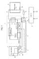
- FIG. 1 is a diagrammatic view of the hot water storage type hot water supply system according to the embodiment.
- the hot water storage type hot water supply system includes: heat pump cycle 1, water storage tank 2, secondary battery 3 that is a battery part, water circulation path 4, first path 5, second path 6, first heat exchanger 7, second heat exchanger 8, and controller 9.
- the heat pump cycle 1 includes: evaporator 12, compressor 11, radiator 12, expansion valve 13, and piping 14 that couples these parts in this order.
- a working medium (a first refrigerant, not shown) is enclosed.
- the working medium employs water, hydrocarbon, ammonia, or alternative chlorofluorocarbon, for example.
- Water in water storage tank 2 flows out from an outflow port (not shown) at a lower portion of water storage tank 2 into water circulation path 4, flows through first heat exchanger 7 and radiator 10 in this order, and then flows into water storage tank 2 from an inflow port (not shown) at an upper portion of water storage tank 2. That is, in water circulation path 4, first heat exchanger 7 is located upstream relative to radiator 12. Moreover, in water circulation path 4, pump 15 is disposed to circulate the water.
- first path 5 and second path 6 a refrigerant (a second refrigerant) is enclosed.
- the second refrigerant employs, for example, water, hydrocarbon, ammonia, or alternative chlorofluorocarbon, in a similar way to the working medium (the first refrigerant).
- the refrigerant (the second refrigerant) circulates through second heat exchanger 8 and evaporator 10 in this order, with the exchanger performing heat exchange with secondary battery 3,
- pump 16 is disposed to circulate the refrigerant (the second refrigerant).
- second path 6 is formed and branched off from first path 5 via switching-valve 7; second path 6 becomes usable by switching from first path 5 to the second path.
- the refrigerant (the second refrigerant) is configured to circulate from switching-valve 17 through first heat exchanger 7 and second heat exchanger 8 to original switching-valve 17.
- first temperature detector 18 is disposed. Temperature information detected by first temperature detector 18 is inputted to controller 9.
- second temperature detector 19 is disposed in water storage tank 2. Temperature information detected by second temperature detector 19 is inputted to controller 9.
- second temperature detector 19 is preferably disposed at a lower interior portion of water storage tank 2. This allows measurements of temperature of the water flowing from water storage tank 2 into water circulation path 4, resulting in more accurate measurements of the temperature of the water that flows into first heat exchanger 7.
- the working medium deprives outside air of heat to form a low temperature and pressure gas.
- Evaporator 10 not only deprives the outside air of the heat but also obtains heat from the second refrigerant flowing in first path 5 so as to evaporate the working medium.
- heat sources supplying heat to evaporator 10 are not limited particularly to such outside air and the second refrigerant.
- liquids such as water and exhaust gases or the like can also be used.
- compressor 11 the working medium is compressed to high temperatures and pressures.
- radiator 12 the heat of the working medium is released through a heat exchange with such as water, air, and refrigerants of the outside of the cycle.
- radiator 12 performs the heat exchange between the working medium flowing in piping 14 and the water flowing in water circulation path 4 so as to heat the water.
- expansion valve 13 the high-pressure working medium undergoes depressurization to return to a low temperature and pressure liquid.
- the water in water storage tank 2 circulates in water circulation path 4 coupled with water storage tank 2.
- Water circulation path 4 is configured such that the water flows out from the lower portion of water storage tank 2 and flows in from the upper portion of water storage tank 2.
- the working medium the first refrigerant
- This supplies the heat, via radiator 12, from the working medium (the first refrigerant) to the water of relatively low temperatures that flows out from the lower portion of water storage tank 2.
- the water of high temperatures thus heated by the supplied heat, flows into the upper portion of water storage tank 2 from water circulation path 4.
- the thus-heated water in water storage tank 2 is supplied to external loads including a hot-water supply and heating, for example.
- Secondary battery 3 serving as a battery part is charged with power from system electric power at night. Besides the system electric power, a power generator using natural energies (a solar cell, for example) or a fuel cell may also be employed for power charging.
- the power stored in secondary battery 3 is utilized to operate compressor 11 of heat pump cycle 1, for example. With such a configuration, cheap nighttime power can be utilized to operate heat pump cycle 1. Besides this, the power stored in secondary battery 3 can be used for a wide range of electricity-consuming apparatus including a household refrigerator and a TV receiver, for example.
- FIG. 2 is a flow-chart of a control processing performed, every predetermined period of time, by controller 9 of the hot water storage type hot water supply system according to the embodiment.
- secondary battery 3 is configured to be capable of performing the heat exchange with the refrigerant (the second refrigerant) flowing in first path 5 and the second path, via second heat exchanger 8.
- Secondary battery 3 generally shows a large variation in charge-discharge performance depending on temperature.
- a commonly-used lithium-ion secondary battery shows temperature characteristics that exhibit: a small discharge-charge loss and a small degradation of the battery at ordinary temperature (approximately 25°C); an increased degradation with increasing temperature from the ordinary temperature to higher temperatures; and an increased discharge-charge loss and an increased degradation with decreasing temperature from the ordinary temperature.
- controller 9 holds secondary battery 3 in an optimal range of temperature by switching between the paths in which second refrigerant circulates.
- switching-valve 17 When secondary battery 3 is operated at an optimal temperature (approximately 25°C), switching-valve 17 is closed such that the refrigerant flows in neither first path 5 nor second path 6.
- Step S01 a judgment is made whether or not the temperature of secondary battery 3 detected by first temperature detector 18 is higher than predetermined temperature TBh (a first predetermined temperature) (Step S01).
- TBh is an upper limit of the optimal temperature for operating secondary battery 3, and is set to 35°C, for example.
- controller 9 switches switching-valve 17 toward first path 5 (Step S02). This allows the refrigerant (the second refrigerant) to circulate in first path 5.
- the heat exchange is performed between the refrigerant (the second refrigerant) flowing in first path 5 and the working medium (the first refrigerant) flowing in piping 14.
- the heat exchange is performed between secondary battery 3 and the refrigerant (the second refrigerant) flowing in first path 5.
- the heat held by secondary battery 3 travels to the working medium (the first refrigerant). Therefore, secondary battery 3 is cooled by providing the heat held by itself for the working medium (the first refrigerant).
- evaporator 10 causes the working medium to evaporate by utilizing the heat obtained from secondary battery 3.
- Controller 9 continues to perform this control until the temperature of secondary battery 3 detected by temperature detector 18 decreases to not higher than TBh (Step S03). In the case where the temperature of secondary battery 3 decreases to not higher than TBh (Yes in Step S03), the controller closes switching-valve 17 (Step S04).
- Step S05 a judgment is made whether or not the temperature of secondary battery 3 is lower than predetermined temperature TB1 (a second predetermined temperature) (Step S05).
- TB1 is a lower limit of the optimal temperature for operating secondary battery 3, and is set to 10°C, for example.
- controller 9 judges that secondary battery 3 is at the optimal temperature. In this situation, if switching-valve 17 is being opened, controller 9 closes switching-valve 17 (Step S04).
- controller 9 judges whether or not the temperature of the water in water storage tank 2 detected by second temperature detector 19 is not lower than predetermined temperature TW (a third predetermined temperature) (Step S06).
- TW is preferably set to a temperature not lower than TB1 described above, for example, to 20°C.
- controller 9 switches switching-valve 17 toward second path 6 (Step S07).
- This configuration allows the refrigerant (the second refrigerant) to circulate in second path 6. Then, in first heat exchanger 7, a heat exchange is performed between the refrigerant (the second refrigerant) flowing in second path 6 and the water flowing in water circulation path 4. Moreover, in second heat exchanger 8, the heat exchange is performed between secondary battery 3 and the refrigerant (the second refrigerant) flowing in second path 6.
- the temperature of the water flowing in first heat exchanger 7 is higher than the temperature of secondary battery 3, which thereby allows heat to travel from the water flowing in water circulation path 4 to secondary battery 3. Therefore, secondary battery 3 is heated and adjusted to the optimal temperature. Moreover, the temperature of the water is decreased by providing the heat for secondary battery 3.
- Controller 9 continues to perform this control until the temperature of secondary battery 3 detected by temperature detector 18 increases to not lower than TB1 (Step S08). In the case where the temperature of secondary battery 3 increases to not lower than TB1 (Yes in Step S08), the controller closes switching-valve 17 (Step S04).
- controller 9 does not switch switching-valve 17 in the case where the temperature of the water in water storage tank 2 is lower than TW (No in Step S06). However, if switching-valve 17 is being opened, controller 9 closes switching-valve 17 (Step S04). After a predetermined period of time during which the heat pump is continuously operated without a halt, controller 9 makes the judgment in Step S06 again. In the case where the temperature of the water in water storage tank 2 increases to higher than TW (Yes in Step S06), switching-valve 17 is switched toward second path 6 (Step S07) to provide heat for secondary battery 3.
- FIG. 3 is a diagrammatic view of another hot water storage type hot water supply system according to the embodiment. Explanations of configuration and operation the same as those shown in FIGS. 1 and 2 are omitted, but explanations will be made focusing on differences from those in the figures.
- a difference from FIGS. 1 and 2 is in that first path 5 and second path 6 are each formed as an independent path of one another.
- first path 5 and the second path refrigerants (the second refrigerant and a third refrigerant, respectively) are enclosed.
- pump 16 is disposed to circulate the refrigerant.
- pump 21 is disposed to circulate the refrigerant.
- first path 5 and second path 6 second heat exchanger 8 and third heat exchanger 20 are disposed, respectively, to perform heat exchanges with secondary battery 3.
- FIG. 4 is a flow-chart of a control processing performed , every predetermined period of time, by controller 9 of the hot water storage type hot water supply system shown in FIG. 3 .
- secondary battery 3 is configured to be capable of performing a heat exchange, via second heat exchanger 8, with the refrigerant (the second refrigerant) flowing in first path 5. Moreover, secondary battery 3 is configured to be capable of performing a heat exchange, via third heat exchanger 20, with the refrigerant (the third refrigerant) flowing in second path 6 formed independently of the first path.
- Step S01 a judgment is made whether or not the temperature of secondary battery 3 detected by first temperature detector 18 is higher than predetermined temperature TBh (a first predetermined temperature) (Step S01).
- TBh is an upper limit of the optimal temperature for operating secondary battery 3, and is set to 35°C, for example.
- controller 9 causes pump 16 to work and pump 21 to halt (Step S09). This allows the refrigerant (the second refrigerant) to circulate in first path 5.
- evaporator 10 a heat exchange is performed between the refrigerant (the second refrigerant) flowing in first path 5 and the working medium (the first refrigerant) flowing in piping 14. Moreover, in second heat exchanger 8, the heat exchange is performed between secondary battery 3 and the refrigerant (the second refrigerant) flowing in first path 5. As a result, the heat held by secondary battery 3 travels to the working medium (the first refrigerant). Therefore, secondary battery 3 is cooled by providing the heat held by itself for the working medium (the first refrigerant). Meanwhile, evaporator 10 causes the working medium to evaporate by utilizing the heat obtained from secondary battery 3.
- Controller 9 continues to perform this control until the temperature of secondary battery 3 detected by temperature detector 18 decreases to not higher than TBh (Step S03). In the case where the temperature of secondary battery 3 decreases to not higher than TBh (Yes in Step S03), the controller halts the operation of pump 16 (Step S10).
- Step S05 a judgment is made whether or not the temperature of secondary battery 3 is lower than predetermined temperature TB1 (a second predetermined temperature) (Step S05).
- TB1 is a lower limit of the optimal temperature for operating secondary battery 3, and is set to 10°C, for example.
- controller 9 judges that secondary battery 3 is at the optimal temperature. In this situation, if pumps 16 and 21 are working, the operation of both the pumps is halted (Step S13).
- controller 9 judges whether or not the temperature of the water in water storage tank 2 detected by second temperature detector 19 is not lower than predetermined temperature TW (a third predetermined temperature) (Step S06).
- TW is preferably set to a temperature not lower than TB1 described above, for example, to 20°C.
- controller 9 causes the refrigerant in second path 6 to flow, by causing pump 21 to work and pump 16 to halt (Step S11). This configuration allows the refrigerant (the third refrigerant) to circulate in second path 6.
- first heat exchanger 7 a heat exchange is performed between the refrigerant (the third refrigerant) flowing in second path 6 and the water flowing in water circulation path 4.
- third heat exchanger 20 the heat exchange is performed between secondary battery 3 and the refrigerant (the third refrigerant) flowing in second path 6.
- the temperature of the water flowing into first heat exchanger 7 is higher than the temperature of secondary battery 3, which thereby allows heat to travel from the water flowing in water circulation path 4 to secondary battery 3. Therefore, secondary battery 3 is heated and adjusted to the optimal temperature.
- the temperature of the water decreases to the optimal temperature described above. Accordingly, in radiator 12, the heat exchange with the working medium (the first refrigerant) is performed more efficiently.
- Controller 9 continues to perform this control until the temperature of secondary battery 3 detected by temperature detector 18 increases to not lower than TB1 (Step S08). In the case where the temperature of secondary battery 3 increases to not lower than TB1 (Yes in Step S08), the controller halts the operation of pump 21 (Step S12).
- controller 9 allows neither pumps 16 nor 21 to work. However, if pumps 16 and 21 are working, the controller causes pumps 16 and 21 to halt. And, after a predetermined period of time during which heat pump 1 is continuously operated without a halt, controller 9 makes the judgment in Step S06 again. In the case where the temperature of the water in water storage tank 2 increases to not lower than TW (Yes in Step S06), only pump 21 is allowed to work so as to switch the path to second path 6 (Step S11), thereby providing heat for secondary battery 3.
- Step S06 the judgment in Step S06 may be omitted. That is, when the temperature of the secondary battery is lower than TB1, the refrigerant in second path 6 may be controlled so as for it to flow, independently of the temperature of the water in water storage tank 2. In many cases, the temperature of the water in water storage tank 2 is not lower than TB1. And, even if this is not the case, the temperature of the water in water storage tank 2 increases due to the operation of the heat pump. Hence, it is possible to sufficiently achieve the advantages of the invention.
- the hot water storage type hot water supply system is such that the temperature of secondary battery 3 serving as a battery part can be controlled to the optimal temperature in such a way as follows.
- the path in which the second refrigerant flows is switched over.
- the second and third paths independent of one another are switched between them such that the second and third refrigerants of different temperatures flow in the paths, respectively.
- the heat generated through heating and cooling of secondary battery 3 can be effectively used in heat pump cycle 1 to improve the efficiency of heat pump cycle 1 as well.
- the battery part employs secondary battery 3
- the battery part may be configured to employ elements including an electric double-layer capacitor other than secondary battery 3.
- the object to be temperature-controlled is not limited to the battery part. Any of objects which are preferably expected to be adjusted to within a particular range of temperature may be employed as one to be temperature-controlled.
- the hot water storage type hot water supply system it is possible to improve the efficiency of the heat pump cycle as well as the charge-discharge efficiency of the battery part, by adjusting the battery part to the optimal temperature. Accordingly, the system is useful for household systems including a hot water storage type heat pump system.
- REFERENCE MARKS IN THE DRAWINGS 1 heat pump cycle 2 water storage tank 3 secondary battery (battery part) 4 water circulation path 5 first path 6 second path 7 first heat exchanger 8 second heat exchanger 9 controller 10 evaporator 11 compressor 12 radiator 13 expansion valve 14 piping 15 pump 16 pump 17 switching-valve 18 first temperature detector 19 second temperature detector 20 third heat exchanger 21 pump
Landscapes
- Engineering & Computer Science (AREA)
- Chemical & Material Sciences (AREA)
- Manufacturing & Machinery (AREA)
- Chemical Kinetics & Catalysis (AREA)
- Electrochemistry (AREA)
- General Chemical & Material Sciences (AREA)
- Physics & Mathematics (AREA)
- Thermal Sciences (AREA)
- Combustion & Propulsion (AREA)
- Mechanical Engineering (AREA)
- General Engineering & Computer Science (AREA)
- Water Supply & Treatment (AREA)
- Electromagnetism (AREA)
- Automation & Control Theory (AREA)
- Heat-Pump Type And Storage Water Heaters (AREA)
- Secondary Cells (AREA)
Applications Claiming Priority (2)
| Application Number | Priority Date | Filing Date | Title |
|---|---|---|---|
| JP2010154564 | 2010-07-07 | ||
| PCT/JP2011/003850 WO2012004985A1 (fr) | 2010-07-07 | 2011-07-06 | Système d'alimentation en eau chaude du type à réservoir d'eau chaude et procédé d'exploitation de celui-ci |
Publications (3)
| Publication Number | Publication Date |
|---|---|
| EP2610560A1 true EP2610560A1 (fr) | 2013-07-03 |
| EP2610560A4 EP2610560A4 (fr) | 2016-03-16 |
| EP2610560B1 EP2610560B1 (fr) | 2016-12-07 |
Family
ID=45440974
Family Applications (1)
| Application Number | Title | Priority Date | Filing Date |
|---|---|---|---|
| EP11799599.3A Not-in-force EP2610560B1 (fr) | 2010-07-07 | 2011-07-06 | Système d'alimentation en eau chaude du type à réservoir d'eau chaude et procédé d'exploitation de celui-ci |
Country Status (5)
| Country | Link |
|---|---|
| US (1) | US8365546B2 (fr) |
| EP (1) | EP2610560B1 (fr) |
| JP (1) | JP4952867B2 (fr) |
| CN (1) | CN102549348B (fr) |
| WO (1) | WO2012004985A1 (fr) |
Families Citing this family (23)
| Publication number | Priority date | Publication date | Assignee | Title |
|---|---|---|---|---|
| US9562696B2 (en) * | 2010-04-15 | 2017-02-07 | Mitsubishi Electric Corporation | Hot water supply system control apparatus and hot water supply system control program and hot water supply system operating method |
| US8972073B2 (en) | 2010-11-10 | 2015-03-03 | Panasonic Corporation | Operation planning method, operation planning device, heat pump hot water supply system operation method, and heat pump hot water supply and heating system operation method |
| EP2660942B1 (fr) | 2010-12-27 | 2019-03-13 | Panasonic Intellectual Property Management Co., Ltd. | Procédé de planification du fonctionnement |
| KR101141946B1 (ko) * | 2011-06-08 | 2012-05-04 | 삼성에버랜드 주식회사 | 복합 발전 시스템 및 복합 발전 시스템의 온수 공급 방법 |
| JP5670853B2 (ja) * | 2011-09-27 | 2015-02-18 | 株式会社東芝 | 空調システム |
| WO2013084301A1 (fr) * | 2011-12-06 | 2013-06-13 | 三菱電機株式会社 | Système de chauffage de type pompe à chaleur/d'alimentation en eau chaude |
| JP6089670B2 (ja) * | 2012-12-14 | 2017-03-08 | ダイキン工業株式会社 | 給湯システム |
| JP6357675B2 (ja) * | 2013-03-19 | 2018-07-18 | 本田技研工業株式会社 | 電力供給システム |
| JP6344015B2 (ja) * | 2014-03-31 | 2018-06-20 | ダイキン工業株式会社 | 給湯システム |
| JP6515441B2 (ja) * | 2014-03-31 | 2019-05-22 | ダイキン工業株式会社 | 給湯システム |
| CN104157928A (zh) * | 2014-08-04 | 2014-11-19 | 北京新能源汽车股份有限公司 | 一种动力电池组的热管理系统及方法 |
| CN104577256A (zh) * | 2014-12-02 | 2015-04-29 | 中联重科股份有限公司渭南分公司 | 一种工程机械及其蓄电池加热装置 |
| WO2016133145A1 (fr) | 2015-02-18 | 2016-08-25 | 古河電気工業株式会社 | Dispositif de régulation de température de batterie et système de régulation de température de batterie |
| CN104993189B (zh) * | 2015-07-22 | 2018-09-18 | 贵州大学 | 一种锂电池组液冷的热管理结构 |
| CN109565087B (zh) * | 2016-08-30 | 2021-11-26 | 三洋电机株式会社 | 管理装置和蓄电系统 |
| CN106931680B (zh) * | 2017-03-31 | 2022-08-30 | 武汉地质资源环境工业技术研究院有限公司 | 一种氢能和太阳能互补的热泵系统及其运行方法 |
| JP6818625B2 (ja) * | 2017-04-28 | 2021-01-20 | 三菱電機株式会社 | 給湯システム |
| JP6952864B2 (ja) * | 2018-02-23 | 2021-10-27 | 三菱電機株式会社 | 給湯装置 |
| CN109411849B (zh) * | 2019-01-23 | 2019-04-16 | 常州江苏大学工程技术研究院 | 动力电池包冷却与加热系统及使用该系统的方法 |
| FR3117195B1 (fr) * | 2020-12-03 | 2023-02-24 | Lancey Energy Storage | Système thermique incluant une pompe à chaleur comprenant deux types de compresseur |
| DE102022101847A1 (de) | 2022-01-27 | 2023-07-27 | Audi Aktiengesellschaft | Energiespeichereinheit, Wärmepumpenheizeinrichtung und Energiespeichersystem |
| CN115127254B (zh) * | 2022-08-31 | 2022-12-09 | 河北工业大学 | 一种基于储能电站的电池热管理余热回收供冷供热系统 |
| CN117490272A (zh) * | 2023-11-28 | 2024-02-02 | 广州市耀华制冷设备有限公司 | 一种节能系统 |
Family Cites Families (11)
| Publication number | Priority date | Publication date | Assignee | Title |
|---|---|---|---|---|
| JPH08138761A (ja) | 1994-11-10 | 1996-05-31 | Mitsubishi Heavy Ind Ltd | 電力貯蔵型ヒートポンプシステム |
| JP3849375B2 (ja) * | 1999-11-18 | 2006-11-22 | 松下電器産業株式会社 | 熱電併給装置 |
| JP2004239510A (ja) | 2003-02-05 | 2004-08-26 | Seishiro Munehira | 蓄熱温水器 |
| JP4159975B2 (ja) | 2003-12-02 | 2008-10-01 | 松下電器産業株式会社 | 蓄エネ式ヒートポンプ給湯機 |
| JP5127426B2 (ja) | 2007-12-18 | 2013-01-23 | トヨタ自動車株式会社 | 電動車両の充電システム |
| CN101617431B (zh) * | 2007-12-18 | 2012-02-01 | 松下电器产业株式会社 | 热电联产系统 |
| US20090249802A1 (en) * | 2008-04-04 | 2009-10-08 | Gm Global Technology Operations, Inc. | Vehicle HVAC and Battery Thermal Management |
| JP2009266556A (ja) | 2008-04-24 | 2009-11-12 | Toyota Motor Corp | 蓄電装置及び熱利用システム |
| JP5003607B2 (ja) | 2008-06-18 | 2012-08-15 | 株式会社デンソー | 給湯システム |
| JP5012695B2 (ja) | 2008-06-26 | 2012-08-29 | 株式会社デンソー | 給湯システム |
| JP2010050000A (ja) * | 2008-08-22 | 2010-03-04 | Sanyo Electric Co Ltd | 車両用の電源装置 |
-
2011
- 2011-07-06 EP EP11799599.3A patent/EP2610560B1/fr not_active Not-in-force
- 2011-07-06 CN CN201180003092.3A patent/CN102549348B/zh not_active Expired - Fee Related
- 2011-07-06 JP JP2011553633A patent/JP4952867B2/ja not_active Expired - Fee Related
- 2011-07-06 WO PCT/JP2011/003850 patent/WO2012004985A1/fr active Application Filing
- 2011-07-06 US US13/381,452 patent/US8365546B2/en not_active Expired - Fee Related
Also Published As
| Publication number | Publication date |
|---|---|
| JPWO2012004985A1 (ja) | 2016-05-26 |
| JP4952867B2 (ja) | 2012-06-13 |
| EP2610560A4 (fr) | 2016-03-16 |
| EP2610560B1 (fr) | 2016-12-07 |
| CN102549348B (zh) | 2014-07-23 |
| CN102549348A (zh) | 2012-07-04 |
| US20120186278A1 (en) | 2012-07-26 |
| WO2012004985A1 (fr) | 2012-01-12 |
| US8365546B2 (en) | 2013-02-05 |
Similar Documents
| Publication | Publication Date | Title |
|---|---|---|
| EP2610560B1 (fr) | Système d'alimentation en eau chaude du type à réservoir d'eau chaude et procédé d'exploitation de celui-ci | |
| KR101776751B1 (ko) | 차량용 배터리 냉각 시스템 제어방법 | |
| US10571077B2 (en) | Cooled-hydrogen supply station and a cooling apparatus for hydrogen | |
| Ahn et al. | Heating performance characteristics of a dual source heat pump using air and waste heat in electric vehicles | |
| JP5786957B2 (ja) | 冷却装置 | |
| JP6150113B2 (ja) | 車両熱管理システム | |
| US20150017492A1 (en) | Temperature regulation device | |
| KR102189464B1 (ko) | 난방 시스템 | |
| KR20170108447A (ko) | 차량용 배터리 냉각 시스템 제어방법 | |
| KR20170067502A (ko) | 차량용 배터리 냉각 시스템 | |
| EP2388532B1 (fr) | Dispositif d'alimentation en eau chaude avec une pompe à chaleur | |
| US20160129757A1 (en) | Air conditioning device for vehicle | |
| KR101427924B1 (ko) | 연료 전지 시스템의 압축 공기 냉각 장치 | |
| JP2013187159A (ja) | 電池システム及びその温度制御方法 | |
| JP2008111650A (ja) | 太陽光発電・集熱複合利用装置 | |
| US10935287B2 (en) | Heat pump system | |
| US10720684B2 (en) | Thermal management system for battery | |
| KR102402125B1 (ko) | 에너지 저장 시스템 온도 조절 장치 | |
| JP2010007950A (ja) | コージェネレーションシステム | |
| KR102445224B1 (ko) | 차량용 히트 펌프 시스템 | |
| JP2012081932A (ja) | 駆動用バッテリ温度調整システム | |
| CN107719151B (zh) | 储热系统、储热系统的控制方法和车辆 | |
| CN105865077B (zh) | 使用兰金循环和热电模块的冷却系统及其控制方法 | |
| WO2015094097A1 (fr) | Agencement et procédé pour réguler la température d'un système de stockage d'énergie électrique dans un véhicule | |
| JP6705771B2 (ja) | 圧縮空気貯蔵発電装置 |
Legal Events
| Date | Code | Title | Description |
|---|---|---|---|
| PUAI | Public reference made under article 153(3) epc to a published international application that has entered the european phase |
Free format text: ORIGINAL CODE: 0009012 |
|
| 17P | Request for examination filed |
Effective date: 20120105 |
|
| AK | Designated contracting states |
Kind code of ref document: A1 Designated state(s): AL AT BE BG CH CY CZ DE DK EE ES FI FR GB GR HR HU IE IS IT LI LT LU LV MC MK MT NL NO PL PT RO RS SE SI SK SM TR |
|
| DAX | Request for extension of the european patent (deleted) | ||
| RAP1 | Party data changed (applicant data changed or rights of an application transferred) |
Owner name: PANASONIC INTELLECTUAL PROPERTY MANAGEMENT CO., LT |
|
| RA4 | Supplementary search report drawn up and despatched (corrected) |
Effective date: 20160211 |
|
| RIC1 | Information provided on ipc code assigned before grant |
Ipc: F24H 1/00 20060101AFI20160205BHEP Ipc: H01M 10/66 20140101ALI20160205BHEP Ipc: F24H 1/18 20060101ALI20160205BHEP Ipc: H01M 8/00 20160101ALI20160205BHEP |
|
| RIC1 | Information provided on ipc code assigned before grant |
Ipc: H01M 10/66 20140101ALI20160511BHEP Ipc: F24H 1/18 20060101ALI20160511BHEP Ipc: H01M 8/00 20160101ALI20160511BHEP Ipc: F24H 1/00 20060101AFI20160511BHEP |
|
| GRAP | Despatch of communication of intention to grant a patent |
Free format text: ORIGINAL CODE: EPIDOSNIGR1 |
|
| INTG | Intention to grant announced |
Effective date: 20160622 |
|
| GRAS | Grant fee paid |
Free format text: ORIGINAL CODE: EPIDOSNIGR3 |
|
| GRAA | (expected) grant |
Free format text: ORIGINAL CODE: 0009210 |
|
| STAA | Information on the status of an ep patent application or granted ep patent |
Free format text: STATUS: THE PATENT HAS BEEN GRANTED |
|
| AK | Designated contracting states |
Kind code of ref document: B1 Designated state(s): AL AT BE BG CH CY CZ DE DK EE ES FI FR GB GR HR HU IE IS IT LI LT LU LV MC MK MT NL NO PL PT RO RS SE SI SK SM TR |
|
| REG | Reference to a national code |
Ref country code: GB Ref legal event code: FG4D |
|
| REG | Reference to a national code |
Ref country code: CH Ref legal event code: EP Ref country code: AT Ref legal event code: REF Ref document number: 852096 Country of ref document: AT Kind code of ref document: T Effective date: 20161215 |
|
| REG | Reference to a national code |
Ref country code: IE Ref legal event code: FG4D |
|
| REG | Reference to a national code |
Ref country code: DE Ref legal event code: R096 Ref document number: 602011033205 Country of ref document: DE |
|
| PG25 | Lapsed in a contracting state [announced via postgrant information from national office to epo] |
Ref country code: LV Free format text: LAPSE BECAUSE OF FAILURE TO SUBMIT A TRANSLATION OF THE DESCRIPTION OR TO PAY THE FEE WITHIN THE PRESCRIBED TIME-LIMIT Effective date: 20161207 |
|
| REG | Reference to a national code |
Ref country code: LT Ref legal event code: MG4D |
|
| REG | Reference to a national code |
Ref country code: NL Ref legal event code: MP Effective date: 20161207 |
|
| PG25 | Lapsed in a contracting state [announced via postgrant information from national office to epo] |
Ref country code: GR Free format text: LAPSE BECAUSE OF FAILURE TO SUBMIT A TRANSLATION OF THE DESCRIPTION OR TO PAY THE FEE WITHIN THE PRESCRIBED TIME-LIMIT Effective date: 20170308 Ref country code: NO Free format text: LAPSE BECAUSE OF FAILURE TO SUBMIT A TRANSLATION OF THE DESCRIPTION OR TO PAY THE FEE WITHIN THE PRESCRIBED TIME-LIMIT Effective date: 20170307 Ref country code: LT Free format text: LAPSE BECAUSE OF FAILURE TO SUBMIT A TRANSLATION OF THE DESCRIPTION OR TO PAY THE FEE WITHIN THE PRESCRIBED TIME-LIMIT Effective date: 20161207 Ref country code: SE Free format text: LAPSE BECAUSE OF FAILURE TO SUBMIT A TRANSLATION OF THE DESCRIPTION OR TO PAY THE FEE WITHIN THE PRESCRIBED TIME-LIMIT Effective date: 20161207 |
|
| REG | Reference to a national code |
Ref country code: AT Ref legal event code: MK05 Ref document number: 852096 Country of ref document: AT Kind code of ref document: T Effective date: 20161207 |
|
| PG25 | Lapsed in a contracting state [announced via postgrant information from national office to epo] |
Ref country code: ES Free format text: LAPSE BECAUSE OF FAILURE TO SUBMIT A TRANSLATION OF THE DESCRIPTION OR TO PAY THE FEE WITHIN THE PRESCRIBED TIME-LIMIT Effective date: 20161207 Ref country code: FI Free format text: LAPSE BECAUSE OF FAILURE TO SUBMIT A TRANSLATION OF THE DESCRIPTION OR TO PAY THE FEE WITHIN THE PRESCRIBED TIME-LIMIT Effective date: 20161207 Ref country code: HR Free format text: LAPSE BECAUSE OF FAILURE TO SUBMIT A TRANSLATION OF THE DESCRIPTION OR TO PAY THE FEE WITHIN THE PRESCRIBED TIME-LIMIT Effective date: 20161207 Ref country code: RS Free format text: LAPSE BECAUSE OF FAILURE TO SUBMIT A TRANSLATION OF THE DESCRIPTION OR TO PAY THE FEE WITHIN THE PRESCRIBED TIME-LIMIT Effective date: 20161207 |
|
| PG25 | Lapsed in a contracting state [announced via postgrant information from national office to epo] |
Ref country code: NL Free format text: LAPSE BECAUSE OF FAILURE TO SUBMIT A TRANSLATION OF THE DESCRIPTION OR TO PAY THE FEE WITHIN THE PRESCRIBED TIME-LIMIT Effective date: 20161207 |
|
| PG25 | Lapsed in a contracting state [announced via postgrant information from national office to epo] |
Ref country code: SK Free format text: LAPSE BECAUSE OF FAILURE TO SUBMIT A TRANSLATION OF THE DESCRIPTION OR TO PAY THE FEE WITHIN THE PRESCRIBED TIME-LIMIT Effective date: 20161207 Ref country code: CZ Free format text: LAPSE BECAUSE OF FAILURE TO SUBMIT A TRANSLATION OF THE DESCRIPTION OR TO PAY THE FEE WITHIN THE PRESCRIBED TIME-LIMIT Effective date: 20161207 Ref country code: EE Free format text: LAPSE BECAUSE OF FAILURE TO SUBMIT A TRANSLATION OF THE DESCRIPTION OR TO PAY THE FEE WITHIN THE PRESCRIBED TIME-LIMIT Effective date: 20161207 Ref country code: IS Free format text: LAPSE BECAUSE OF FAILURE TO SUBMIT A TRANSLATION OF THE DESCRIPTION OR TO PAY THE FEE WITHIN THE PRESCRIBED TIME-LIMIT Effective date: 20170407 Ref country code: RO Free format text: LAPSE BECAUSE OF FAILURE TO SUBMIT A TRANSLATION OF THE DESCRIPTION OR TO PAY THE FEE WITHIN THE PRESCRIBED TIME-LIMIT Effective date: 20161207 |
|
| PG25 | Lapsed in a contracting state [announced via postgrant information from national office to epo] |
Ref country code: SM Free format text: LAPSE BECAUSE OF FAILURE TO SUBMIT A TRANSLATION OF THE DESCRIPTION OR TO PAY THE FEE WITHIN THE PRESCRIBED TIME-LIMIT Effective date: 20161207 Ref country code: IT Free format text: LAPSE BECAUSE OF FAILURE TO SUBMIT A TRANSLATION OF THE DESCRIPTION OR TO PAY THE FEE WITHIN THE PRESCRIBED TIME-LIMIT Effective date: 20161207 Ref country code: PT Free format text: LAPSE BECAUSE OF FAILURE TO SUBMIT A TRANSLATION OF THE DESCRIPTION OR TO PAY THE FEE WITHIN THE PRESCRIBED TIME-LIMIT Effective date: 20170407 Ref country code: PL Free format text: LAPSE BECAUSE OF FAILURE TO SUBMIT A TRANSLATION OF THE DESCRIPTION OR TO PAY THE FEE WITHIN THE PRESCRIBED TIME-LIMIT Effective date: 20161207 Ref country code: BG Free format text: LAPSE BECAUSE OF FAILURE TO SUBMIT A TRANSLATION OF THE DESCRIPTION OR TO PAY THE FEE WITHIN THE PRESCRIBED TIME-LIMIT Effective date: 20170307 Ref country code: AT Free format text: LAPSE BECAUSE OF FAILURE TO SUBMIT A TRANSLATION OF THE DESCRIPTION OR TO PAY THE FEE WITHIN THE PRESCRIBED TIME-LIMIT Effective date: 20161207 Ref country code: BE Free format text: LAPSE BECAUSE OF FAILURE TO SUBMIT A TRANSLATION OF THE DESCRIPTION OR TO PAY THE FEE WITHIN THE PRESCRIBED TIME-LIMIT Effective date: 20161207 |
|
| REG | Reference to a national code |
Ref country code: DE Ref legal event code: R097 Ref document number: 602011033205 Country of ref document: DE |
|
| PLBE | No opposition filed within time limit |
Free format text: ORIGINAL CODE: 0009261 |
|
| STAA | Information on the status of an ep patent application or granted ep patent |
Free format text: STATUS: NO OPPOSITION FILED WITHIN TIME LIMIT |
|
| 26N | No opposition filed |
Effective date: 20170908 |
|
| PG25 | Lapsed in a contracting state [announced via postgrant information from national office to epo] |
Ref country code: DK Free format text: LAPSE BECAUSE OF FAILURE TO SUBMIT A TRANSLATION OF THE DESCRIPTION OR TO PAY THE FEE WITHIN THE PRESCRIBED TIME-LIMIT Effective date: 20161207 Ref country code: SI Free format text: LAPSE BECAUSE OF FAILURE TO SUBMIT A TRANSLATION OF THE DESCRIPTION OR TO PAY THE FEE WITHIN THE PRESCRIBED TIME-LIMIT Effective date: 20161207 |
|
| REG | Reference to a national code |
Ref country code: CH Ref legal event code: PL |
|
| GBPC | Gb: european patent ceased through non-payment of renewal fee |
Effective date: 20170706 |
|
| REG | Reference to a national code |
Ref country code: IE Ref legal event code: MM4A |
|
| REG | Reference to a national code |
Ref country code: FR Ref legal event code: ST Effective date: 20180330 |
|
| PG25 | Lapsed in a contracting state [announced via postgrant information from national office to epo] |
Ref country code: LI Free format text: LAPSE BECAUSE OF NON-PAYMENT OF DUE FEES Effective date: 20170731 Ref country code: CH Free format text: LAPSE BECAUSE OF NON-PAYMENT OF DUE FEES Effective date: 20170731 Ref country code: GB Free format text: LAPSE BECAUSE OF NON-PAYMENT OF DUE FEES Effective date: 20170706 Ref country code: IE Free format text: LAPSE BECAUSE OF NON-PAYMENT OF DUE FEES Effective date: 20170706 |
|
| PG25 | Lapsed in a contracting state [announced via postgrant information from national office to epo] |
Ref country code: FR Free format text: LAPSE BECAUSE OF NON-PAYMENT OF DUE FEES Effective date: 20170731 |
|
| PG25 | Lapsed in a contracting state [announced via postgrant information from national office to epo] |
Ref country code: LU Free format text: LAPSE BECAUSE OF NON-PAYMENT OF DUE FEES Effective date: 20170706 |
|
| PG25 | Lapsed in a contracting state [announced via postgrant information from national office to epo] |
Ref country code: MT Free format text: LAPSE BECAUSE OF NON-PAYMENT OF DUE FEES Effective date: 20170706 |
|
| PGFP | Annual fee paid to national office [announced via postgrant information from national office to epo] |
Ref country code: DE Payment date: 20180723 Year of fee payment: 8 |
|
| PG25 | Lapsed in a contracting state [announced via postgrant information from national office to epo] |
Ref country code: HU Free format text: LAPSE BECAUSE OF FAILURE TO SUBMIT A TRANSLATION OF THE DESCRIPTION OR TO PAY THE FEE WITHIN THE PRESCRIBED TIME-LIMIT; INVALID AB INITIO Effective date: 20110706 Ref country code: MC Free format text: LAPSE BECAUSE OF FAILURE TO SUBMIT A TRANSLATION OF THE DESCRIPTION OR TO PAY THE FEE WITHIN THE PRESCRIBED TIME-LIMIT Effective date: 20161207 |
|
| PG25 | Lapsed in a contracting state [announced via postgrant information from national office to epo] |
Ref country code: CY Free format text: LAPSE BECAUSE OF NON-PAYMENT OF DUE FEES Effective date: 20161207 |
|
| PG25 | Lapsed in a contracting state [announced via postgrant information from national office to epo] |
Ref country code: MK Free format text: LAPSE BECAUSE OF FAILURE TO SUBMIT A TRANSLATION OF THE DESCRIPTION OR TO PAY THE FEE WITHIN THE PRESCRIBED TIME-LIMIT Effective date: 20161207 |
|
| REG | Reference to a national code |
Ref country code: DE Ref legal event code: R119 Ref document number: 602011033205 Country of ref document: DE |
|
| PG25 | Lapsed in a contracting state [announced via postgrant information from national office to epo] |
Ref country code: TR Free format text: LAPSE BECAUSE OF FAILURE TO SUBMIT A TRANSLATION OF THE DESCRIPTION OR TO PAY THE FEE WITHIN THE PRESCRIBED TIME-LIMIT Effective date: 20161207 |
|
| PG25 | Lapsed in a contracting state [announced via postgrant information from national office to epo] |
Ref country code: DE Free format text: LAPSE BECAUSE OF NON-PAYMENT OF DUE FEES Effective date: 20200201 |
|
| PG25 | Lapsed in a contracting state [announced via postgrant information from national office to epo] |
Ref country code: AL Free format text: LAPSE BECAUSE OF FAILURE TO SUBMIT A TRANSLATION OF THE DESCRIPTION OR TO PAY THE FEE WITHIN THE PRESCRIBED TIME-LIMIT Effective date: 20161207 |