EP2610406A1 - Machine de construction - Google Patents
Machine de construction Download PDFInfo
- Publication number
- EP2610406A1 EP2610406A1 EP11819702.9A EP11819702A EP2610406A1 EP 2610406 A1 EP2610406 A1 EP 2610406A1 EP 11819702 A EP11819702 A EP 11819702A EP 2610406 A1 EP2610406 A1 EP 2610406A1
- Authority
- EP
- European Patent Office
- Prior art keywords
- hole
- center
- distance
- boom
- pin
- Prior art date
- Legal status (The legal status is an assumption and is not a legal conclusion. Google has not performed a legal analysis and makes no representation as to the accuracy of the status listed.)
- Withdrawn
Links
Images


Classifications
-
- E—FIXED CONSTRUCTIONS
- E02—HYDRAULIC ENGINEERING; FOUNDATIONS; SOIL SHIFTING
- E02F—DREDGING; SOIL-SHIFTING
- E02F9/00—Component parts of dredgers or soil-shifting machines, not restricted to one of the kinds covered by groups E02F3/00 - E02F7/00
- E02F9/08—Superstructures; Supports for superstructures
- E02F9/0808—Improving mounting or assembling, e.g. frame elements, disposition of all the components on the superstructures
-
- E—FIXED CONSTRUCTIONS
- E02—HYDRAULIC ENGINEERING; FOUNDATIONS; SOIL SHIFTING
- E02F—DREDGING; SOIL-SHIFTING
- E02F9/00—Component parts of dredgers or soil-shifting machines, not restricted to one of the kinds covered by groups E02F3/00 - E02F7/00
- E02F9/006—Pivot joint assemblies
-
- E—FIXED CONSTRUCTIONS
- E02—HYDRAULIC ENGINEERING; FOUNDATIONS; SOIL SHIFTING
- E02F—DREDGING; SOIL-SHIFTING
- E02F9/00—Component parts of dredgers or soil-shifting machines, not restricted to one of the kinds covered by groups E02F3/00 - E02F7/00
- E02F9/08—Superstructures; Supports for superstructures
- E02F9/0808—Improving mounting or assembling, e.g. frame elements, disposition of all the components on the superstructures
- E02F9/0816—Welded frame structure
-
- E—FIXED CONSTRUCTIONS
- E02—HYDRAULIC ENGINEERING; FOUNDATIONS; SOIL SHIFTING
- E02F—DREDGING; SOIL-SHIFTING
- E02F9/00—Component parts of dredgers or soil-shifting machines, not restricted to one of the kinds covered by groups E02F3/00 - E02F7/00
- E02F9/08—Superstructures; Supports for superstructures
- E02F9/10—Supports for movable superstructures mounted on travelling or walking gears or on other superstructures
- E02F9/12—Slewing or traversing gears
- E02F9/121—Turntables, i.e. structure rotatable about 360°
Definitions
- the present invention relates to construction machines such as a hydraulic excavator and, in particular, to a construction machine provided with a revolving frame formed by connecting a tail frame to a rear part side of a center frame.
- a hydraulic excavator as a typical example of a construction machine is largely constituted by a automotive lower traveling structure, an upper revolving structure that is rotatably mounted on the lower traveling structure and forms a vehicle body together with the lower traveling structure, and a working mechanism liftably provided on the front part side of the upper revolving structure.
- the upper revolving structure is formed of a revolving frame, a cab that is provided on a front left side of the revolving frame, an engine and a hydraulic pump mounted on a rear part side of the revolving frame, a housing cover that covers the engine and the like, and a counterweight that is provided on a back end portion of the revolving frame.
- the revolving frame of the upper revolving structure is composed of a center frame forming the center part of the revolving frame, a tail frame connected to the rear part side of the center frame, and left and right side frames provided on both the left and right sides sandwiching the center frame and the tail frame, for example (Patent Document 1).
- the center frame of the revolving frame is composed of a front bottom plate, left and right front vertical plates extending in the front and rear direction on the front bottom plate and erected in the left and right directions with an interval and the front part side is a bracket portion which pin-connects a boom of a working mechanism and a boom cylinder.
- the tail frame is composed of left and right I-section beams joined to the rear part of each front vertical plate and a rear bottom plate which connects each I-section beam to each other.
- the left and right I-section beams of the tail frame are formed of left and right rear vertical plates extending in the front and rear directions and having the front ends joined to each front vertical plate, an upper flange portion provided on the upper side of each rear vertical plate, extending in the front and rear directions and having the front end joined to each front vertical plate, and a lower flange portion provided on the lower side of each rear vertical plate, extending in the front and rear directions and having the front end joined to the front bottom plate.
- a boom pin through hole for performing pin-connection at a foot portion (base end portion) of the boom and a cylinder pin through hole for performing pin-connection of a base end portion of a boom cylinder are provided.
- the foot portion of the boom is rotatably (tiltably) mounted on the bracket portion of the center frame through a boom connecting pin inserted through the boom pin through hole
- the base end portion of the boom cylinder is rotatably mounted on the bracket portion of the center frame through a cylinder connecting pin inserted through the cylinder pin through hole.
- a distance between the foot portion of the boom and the base end portion of the boom cylinder is preferably large.
- a height dimension from the front bottom plate of the center frame to the foot portion of the boom that is, a height dimension from the front bottom plate of the center frame to the hole center of the boom pin through hole can be increased.
- the left and right front vertical plates including the bracket portion should have sufficient strength so as to bear a twisting moment applied from the boom or the like.
- Patent Document 2 discloses a configuration in which strength of the left and right front vertical plates is ensured by providing reinforcing members between the left and right front vertical plates and the front bottom plate.
- Patent Document 3 discloses a configuration in which strength of the front part sides of the left and right vertical plates is ensured by forming the front part sides of the left and right vertical plates (center beam) having a box shape.
- the present invention is applied to a construction machine comprising: a lower traveling structure; an upper revolving structure rotatably mounted on the lower traveling structure; and a working mechanism liftably provided on a front part side of the upper revolving structure, wherein a center frame of a revolving frame constituting the upper revolving structure is composed of a front bottom plate and left and right front vertical plates extending in the front and rear directions on the front bottom plate, erecting in the left and right directions with an interval, and having the front part side being a bracket portion for performing pin-connection of a boom of the working mechanism and a boom cylinder; a tail frame connected to a rear part side of the center frame is composed of left and right I-section beams joined to a rear part of each of the front vertical plates and a rear bottom plate connecting each of the I-section beams to each other; and the left and right I-section beams are formed of left and right rear vertical plates extending in the front and rear directions and
- a feature of the configuration adopted by the present invention is that a boom pin through hole performing pin-connection of a foot portion of the boom is provided on the bracket portion of the center frame; and supposing that a height dimension from the front bottom plate to a hole center of the boom pin through hole is (A) and a height dimension from the front bottom plate to the front end of the upper flange portion is (B), the height dimension (A) is set smaller than the height dimension (B).
- the height dimension from the front bottom plate to the foot portion of the boom can be reduced, and a twisting moment, a bending moment and the like applied to the left and right front vertical plates from the boom can be suppressed by that portion.
- a reinforcing member between the left and right front vertical plates and the front bottom plate or to constitute the front part sides of the left and right vertical plates (center beam) each having a box shape and the size and weight of the center frame can be reduced.
- the height dimension as the entire construction machine can be also reduced by which the height position of the foot portion of the boom can be reduced. Therefore, when a trailer on which the construction machine is loaded travels on a public road, the height dimension can be easily arranged within a range regulated by laws and regulations.
- a cylinder pin through hole performing pin-connection of the boom cylinder is provided in the bracket portion of the center frame on the front side of the boom pin through hole and at a position on the lower side; and supposing that a distance dimension between the hole center of the cylinder pin through hole and the hole center of the boom pin through hole is (C) and a distance in the horizontal direction is (D) when the height dimension (A) is set smaller than the height dimension (B), and supposing that, as a comparison target, a distance dimension between the hole center of a cylinder pin through hole and the hole center of a boom pin through hole is (Cp) and a distance in the horizontal direction is (Dp) when a height dimension (Ap) from a front bottom plate to the hole center of the boom pin through hole is set larger than a height dimension (Bp) from the front bottom plate to the front end of the upper flange portion, the distance (D) is set larger than the distance (Dp) in accordance with a portion by which the
- the distance dimension (D) in the horizontal direction between the hole center of the cylinder pin through hole and the hole center of the boom pin through hole is set larger in accordance with the portion by which the height dimension (A) from the front bottom plate to the hole center of the boom pin through hole is set smaller, the distance dimension (C) between the hole center of the cylinder pin through hole and the hole center of the boom pin through hole can be ensured.
- the height dimension (A) from the front bottom plate to the hole center of the boom pin through hole is set smaller, the distance between the foot portion of the boom and the base end portion of the boom cylinder can be ensured, and the force of the boom cylinder can be effectively used.
- supposing that a distance between a center line (S-S) in the front and rear directions passing through the middle of the left front vertical plate and the right front vertical plate of the center frame and a revolving center (O) of the center frame is (E) when the height dimension (A) is set smaller than the height dimension (B), and supposing that, as a comparison target, a distance between a center line (Sp-Sp) in the front and rear directions passing through the middle of a left front vertical plate and the right front vertical plate of a center frame and a revolving center (Op) of the center frame is (Ep) when the height dimension (Ap) from the front bottom plate to the hole center of the boom pin through hole is set larger than the height dimension (Bp) from the front bottom plate to the front end of the upper flange portion, the distance (E) is set smaller than the distance (Ep).
- a cylinder pin through hole performing pin-connection of the boom cylinder is provided in the bracket portion of the center frame on the front side of the boom pin through hole and at a position on the lower side; and supposing that a distance dimension between the hole center of the cylinder pin through hole and the hole center of the boom pin through hole is (C) and a distance in the horizontal direction is (D) when the height dimension (A) is set smaller than the height dimension (B), and that a distance between a center line (S-S) in the front and rear directions passing through the middle of the left front vertical plate and the right front vertical plate of the center frame and the revolving center (O) of the center frame is (E), supposing that, as a comparison target, a distance dimension between the hole center of the cylinder pin through hole and a hole center of the boom pin through hole is (Cp) and a distance in the horizontal direction is (Dp) when a height dimension (Ap) from a front bottom plate to the hole center of
- the present invention is arranged that a front plate extending in the left and right directions and connecting the left and right front vertical plates is provided on the front part sides between the left and right front vertical plates; and a first bent portion and a second bent portion bent at two spots in the front and rear directions are provided in the front plate.
- the front plate connecting the front part sides of the left and right front vertical plates is configured to be bent at two spots, strength of the front plate can be improved as compared with bending at one spot, and design freedom in an inclination angle of the front plate and the position relationship of the front end portion (lower end portion) of the front plate with respect to the swing circle and the like can be improved.
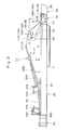
- a wheel-type hydraulic excavator as a typical example of a construction machine, and the hydraulic excavator 1 is largely constituted by an automotive wheel-type lower traveling structure 2, an upper revolving structure 4 that is rotatably mounted on the lower traveling structure 2 through a swing circle 3 and forms a vehicle body together with the lower traveling structure 2, and a working mechanism 5 liftably provided on the front part side of the upper revolving structure 4.
- This wheel-type hydraulic excavator 1 runs on a public road by the wheel-type lower traveling structure 2 and performs earth and sand excavation and the like by using the working mechanism 5 at a work site.
- the lower traveling structure 2 is composed of a truck frame 2A on which the swing circle 3 is mounted on the upper surface side and front and rear wheels 2B provided on the truck frame 2A and driven by a hydraulic motor (not shown).
- the lower traveling structure 2 is configured to travel on a public road, a work site and the like by driving each wheel 2B.
- the upper revolving structure 4 is largely constituted by a revolving frame 11, which will be described later, rotatably mounted on the truck frame 2A of the lower traveling structure 2 through the swing circle 3, a cab 6 provided on the front left side of the revolving frame 11 and defining a driver's room, a counterweight 7 provided on the rear end side of the revolving frame 11 and balancing a weight with the working mechanism 5, a housing cover 8 provided on the front side of the counterweight 7 and accommodating an engine, a hydraulic pump and the like (none of them is shown), an operating oil tank 9 provided on the front side of the housing cover 8, and a fuel tank 10.
- the working mechanism 5 is composed of a lower boom 5A having a base end side rotatably mounted in the upper and lower directions on the front part side of the revolving frame 11 as a boom , an upper boom 5B rotatably mounted on a distal end side of the lower boom 5A, an arm 5C rotatably mounted on the distal end side of the upper boom 5B, a bucket 5D rotatably mounted on the distal end side of the arm 5C, and various cylinders composed of left and right boom cylinders 5E (only the right one is shown), a positioning cylinder 5F, an arm cylinder 5G, and a bucket cylinder 5H.
- a lower boom 5A having a base end side rotatably mounted in the upper and lower directions on the front part side of the revolving frame 11 as a boom
- an upper boom 5B rotatably mounted on a distal end side of the lower boom 5A
- an arm 5C rotatably mounted on the distal end side of the upper boom 5
- the revolving frame 11 is composed of four parts, each of which is integrally joined so as to form a single frame.
- the revolving frame 11 is composed of a center frame 12 located on the front center side, a tail frame 30 located on the rear center side, a left side frame 35 located on the left side sandwiching the center frame 12 and the tail frame 30, and a right side frame 39 similarly located on the right side.
- Designated as 12 is the center frame constituting the center part of the revolving frame 11, and the center frame 12 is largely constituted by a flat-plate shaped front bottom plate 13, a left front vertical plate 14 and a right front vertical plate 17 extending in the front and rear directions on the front bottom plate 13 and erected with an interval in the left and right directions, a front plate 20, which will be described later, located on the front part side of each of the front vertical plates 14 and 17, extending in the left and right directions, and connecting each of the front vertical plates 14 and 17 to each other, a left cylinder mounting plate 21 and a right cylinder mounting plate 22 located on the front side of the front plate 20, extending in the front and rear directions and erected on the front bottom plate 13 with an interval in the left and right directions.
- the front bottom plate 13 of the center frame 12 is the front bottom plate 13 of the center frame 12, and the front bottom plate 13 is formed of a substantially rectangular thick steel plate, for example, and the swing circle 3 is mounted on the lower surface side thereof.
- a plurality of bolt insertion holes 13A are provided in the front bottom plate 13 on the same circumference around the revolving center O, the swing circle 3 is mounted on the lower surface side of the front bottom plate 13 by using mounting bolts (not shown) inserted through each of the bolt insertion holes 13A.
- a center hole 13B through which a center joint (not shown) is inserted is provided in the front bottom plate 13 at a portion corresponding to the revolving center O.
- a revolving apparatus mounting hole 13C on which a revolving apparatus (not shown) is mounted is provided on the rear side of this center hole 13B.
- Designated at 14 is the left front vertical plate located close to the left side on the front bottom plate 13 and erected substantially perpendicularly so as to extend in the front and rear directions.
- This left front vertical plate 14 has the center part in the front and rear directions in the shape of a mountain protruding upward, and the front part side is constituted as a left bracket portion 14A, which will be described later, for pin-connecting the lower boom 5A of the working mechanism 5 and a left boom cylinder (not shown), respectively.
- This left bracket portion 14A is located on the front part side of the left front vertical plate 14 and performs pin-connection between the lower boom 5A and the left boom cylinder.
- the left bracket portion 14A is composed of a left boom mounting plate portion 15 and a left cylinder mounting plate portion 16, which will be described later.
- Indicated at 15 is the left boom mounting plate portion located on the upper part side part of the bracket portion 14A of the left front vertical plate 14, and the left boom mounting plate portion 15 rotatably supports (pin-connection) the foot portion (base end portion) of the lower boom 5A through a boom connecting pin 27, which will be described later.
- a left boom pin through hole 15A through which the boom connecting pin 27 is inserted is provided on the left boom mounting plate portion 15 coaxially with a right boom pin through hole 18A of a right boom mounting plate portion 18, which will be described later.
- the left boom pin through hole 15A is provided at a position lower than the front end of an upper flange portion 31B of an I-section beam 31 constituting the tail frame 30, which will be described later. That is, as illustrated in Figs. 3 and 8 , supposing that a height dimension from the front bottom plate 13 to the hole center of the left boom pin through hole 15A is A and a height dimension from the front bottom plate 13 to the front end of the upper flange portion 31B is B, the height dimension A is set smaller than the height dimension B as shown in the following formula 1.
- a height dimension from the front bottom plate 13 to the foot portion of the lower boom 5A can be reduced, and a twisting moment, a bending moment and the like applied from the lower boom 5A to the left front vertical plate 14 can be suppressed.
- the left cylinder mounting plate portion 16 constituting the left bracket portion 14A of the left front vertical plate 14 together with the left boom mounting plate portion 15, and the left cylinder mounting plate portion 16 is located on the front side and the lower side of the left boom mounting plate portion 15.
- This left cylinder mounting plate portion 16 rotatably supports (pin-connection) the base end portion (bottom portion) of the left boom cylinder through the left cylinder connecting pin (none of them is shown).
- a pair of left cylinder pin through holes 16A and 21A is provided coaxially in the left cylinder mounting plate portion 16 and the left cylinder mounting plate 21, which will be described later, provided oppositely to the left bracket portion 14A of the left front vertical plate 14.
- These left cylinder pin through holes 16A and 21A support the left boom cylinder through the left cylinder connecting pin.
- Designated at 17 is the right front vertical plate provided with an interval in the left and right directions from the left front vertical plate 14 on the front bottom plate 13.
- This right front vertical plate 17 is located close to the right on the front bottom plate 13 and erected substantially perpendicularly so as to extend in the front and rear directions.
- This right front vertical plate 17 has the center part in the front and rear directions in the shape of a mountain protruding upward similarly to the above-described left front vertical plate 14, and the front part side is constituted as a right bracket portion 17A for pin-connecting the lower boom 5A and the right boom cylinder 5E of the working mechanism 5, respectively. That is, this right bracket portion 17A is composed of the right boom mounting plate portion 18, which will be described later, and a right cylinder mounting plate portion 19.
- the right boom mounting plate portion located on the upper part side part of the right bracket portion 17A of the right front vertical plate 17 and rotatably supports (pin-connection) the foot portion (base end portion) of the lower boom 5A through the boom connecting pin 27, which will be described later.
- the right boom pin through hole 18A through which the boom connecting pin 27 is inserted is provided in the right boom mounting plate portion 18 coaxially with the left boom pin through hole 15A of the left boom mounting plate portion 15.
- the right boom pin through hole 18A is also provided at a position lower from the front end of the upper flange portion 32B of the I-section beam 32 constituting the tail frame 30, which will be described later, similarly to the left boom pin through hole 15A. That is, as illustrated in Figs. 3 and 8 , supposing that a height dimension from the front bottom plate 13 to the hole center of the right boom pin through hole 18A is A and a height dimension from the front bottom plate 13 to the front end of an upper flange portion 32B is B, as shown in the formula 1, the height dimension A is set smaller than the height dimension B. As a result, the height dimension from the front bottom plate 13 to the foot portion of the lower boom 5A can be reduced, and a twisting moment, a bending moment and the like applied from the lower boom 5A to the right front vertical plate 17 can be suppressed.
- the right cylinder mounting plate portion constituting the right bracket portion 17A of the right front vertical plate 17 together with the right boom mounting plate portion 18, and the right cylinder mounting plate portion 19 is located on the front side and also on the lower side of the right boom mounting plate portion 18.
- This right cylinder mounting plate portion 19 rotatably supports (pin-connection) the base end portion (bottom portion) of the right boom cylinder 5E through a right cylinder connecting pin 28, which will be described later.
- a pair of right cylinder pin through holes 19A and 22A is coaxially and also coaxially with respect to the left cylinder pin through holes 16A and 21A provided in the right cylinder mounting plate portion 19 and the right cylinder mounting plate 22, which will be described later.
- These right cylinder pin through holes 19A and 22A support the right boom cylinder 5E through the right cylinder connecting pin 28.
- the front plate 20 located on the front side of the front bottom plate 13 and connecting the left and right front vertical plates 14 and 17, and the front plate 20 constitutes a part of the center frame 12.
- the front plate 20 is formed as a three-face plate bent at two spots in the front and rear directions by applying bending to a plate material such as a steel plate and the like, for example.
- the front plate 20 is composed of a front surface portion 20A erecting perpendicularly from the front bottom plate 13, a first bending portion 20B located on the upper end side of the front surface portion 20A and bent toward the rear side, a first inclined portion 20C continuing to the front surface portion 20A through the first bending portion 20B, a second bending portion 20D located on the upper end side of the first inclined portion 20C and bent toward the front side, and a second inclined portion 20E continuing to the first inclined portion 20C through the second bending portion 20D.
- This front plate 20 had a lower end edge of the front surface portion 20A joined to the upper surface of the front bottom plate 13 through welding means, a left end edge joined to the inner side surface of the left front vertical plate 14, and a right end edge joined to the inner side surface of the right front vertical plate 17.
- an opening 20F is formed in the front plate 20 from the front surface portion 20A to the first inclined portion 20C, and the opening 20F is an opening through which a hydraulic hose (not shown) for the working mechanism 5, for example, passes.
- a hydraulic hose (not shown) for the working mechanism 5, for example, passes.
- left and right cylinder mounting plates 21 and 22, which will be described later, are joined to the front surface of the front plate 20 from the front surface portion 20A to the first inclined portion 20C.
- the left cylinder mounting plate 21 provided on the left side front surface of the front plate 20, and the left cylinder mounting plate 21 extends in the front and rear directions and is erected from the front bottom plate 13 to the first inclined portion 20C of the front plate 20.
- the left cylinder mounting plate 21 is opposed to the left cylinder mounting plate portion 16 provided on the left bracket portion 14A of the left front vertical plate 14.
- the left cylinder mounting plate 21 is joined to the left side upper surface of the front bottom plate 13 and the left side front surface of the front plate 20 by using the welding means.
- the left cylinder pin through hole 21A through which the left cylinder connecting pin is inserted is provided in the front end portion of the left cylinder mounting plate 21.
- This left cylinder pin through hole 21A is arranged oppositely to the left cylinder pin through hole 16A provided in the left cylinder mounting plate portion 16.
- the right cylinder mounting plate 22 is the right cylinder mounting plate provided on the right side front surface of the front plate 20, and the right cylinder mounting plate 22 extends in the front and rear directions and is erected from the front bottom plate 13 to the first inclined portion 20C of the front plate 20 similarly to the above-described left cylinder mounting plate 21.
- the right cylinder mounting plate 22 is opposed to the right cylinder mounting plate portion 19 and joined to the right side upper surface of the front bottom plate 13 and to the right side front surface of the front plate 20 by using the welding means.
- the right cylinder pin through hole 22A through which the right cylinder connecting pin 28 is inserted is provided in the front end portion of the right cylinder mounting plate 22, and this right cylinder pin through hole 22A is arranged oppositely to the right cylinder pin through hole 19A.
- Indicated at 23 and 24 are outside reinforcing plates provided on the outer side surfaces of the front portions of the left and right front vertical plates 14 and 17, respectively, and each of the outside reinforcing plates 23 and 24 is joined to outer side surfaces of the portions (portions which become the left and right bracket portions 14A and 17A) where the boom pin through holes 15A and 18A and the cylinder pin through holes 16A and 19A are formed in the left and right front vertical plates 14 and 17 so as to increase the thicknesses of the portions.
- each of the inside reinforcing plates 25 and 26 is joined to inner side surfaces of portions (portions which become left and right boom mounting plate portions 15 and 18) where boom pin through holes 15A and 18A are formed in the left and right front vertical plates 14 and 17 so as to increase the thicknesses of the portions.
- Indicated at 27 is the boom connecting pin which rotatably supports the foot portion of the lower boom 5A on the left and right boom mounting plate portions 15 and 18, and the boom connecting pin 27 is inserted through the left and right boom pin through holes 15A and 18A.
- Indicated at 28 is the right cylinder connecting pin on the bottom side for rotatably supporting the base end portion (bottom portion) of the right boom cylinder 5E between the right cylinder mounting plate portion 19 and the right cylinder mounting plate 22, and the right cylinder connecting pin 28 is inserted through the right cylinder pin through holes 19A and 22A.
- indicated at 29 is the right cylinder connecting pin on the rod side for rotatably supporting the distal end side (rod side) of the right boom cylinder 5E on the lower boom 5A.
- This tail frame 30 is largely constituted by left and right I-section beams 31 and 32, a rear bottom plate 33, and a pair of lateral plates 34, which will be described later.
- each of the I-section beams 31 and 32 is formed having an I-shaped section as a whole.
- Each of these I-section beams 31 and 32 is arranged on the rear side of the left and right front vertical plates 14 and 17 so as to extend in the front and rear directions with an interval in the left and right directions.
- the left I-section beam 31 is formed of a left rear vertical plate 31A extending in the front and rear directions, the upper flange portion 31B joined to the upper end edge of the left rear vertical plate 31A by using the welding means and extending in the front and rear directions, and a lower flange portion 31C joined to the lower end edge of the left rear vertical plate 31A by using the welding means and extending in the front and rear directions.
- the right I-section beam 32 is also formed of a right rear vertical plate 32A, the upper flange portion 32B, and a lower flange portion 32C similarly to the left I-section beam 31.
- the front end side of the tail frame 30 is configured to be connected to the rear end portion of the center frame 12 by the welding means.
- the front end edge of each of the rear vertical plates 31A and 32A is joined to the rear end edge of each of the front vertical plates 14 and 17, the front end portions of the upper flange portions 31B and 32B to the upper surface side on the rear end portion of each of the front vertical plates 14 and 17, and the front end edges of the lower flange portions 31C and 32C and the front end edge of the rear bottom plate 33, which will be described later, to the rear end edge of the front bottom plate 13, respectively.
- the height dimension B of the front ends of the upper flange portions 31B and 32B is larger than the height dimension A of the boom pin through holes 15A and 18A (See Formula 1).
- the rear bottom plate which connects the lower end sides of the left and right I-section beams 31 and 32, and the rear bottom plate 33 is formed having a flat-plate shape by a steel plate or the like and joined to the lower flange portions 31C and 32C of each of the I-section beams 31 and 32 by using the welding means.
- Two openings 33A and 33B are formed in the rear bottom plate 33 and configured so that maintenance and the like of mounted equipment such as an engine or the like from the lower side of the upper revolving structure 4 through each of the openings 33A and 33B can be performed.
- Indicated at 34 are a pair of lateral plates which connect the I-section beams 31 and 32 at two spots in the intermediate portions of the left and right I-section beams 31 and 32, and each of the lateral plates 34 is formed having a flat-plate shape by a steel plate and the like and joined to the upper surface of the rear bottom plate 33 and each of the vertical plates 31A and 32A, the upper flange portions 31B and 32B, and the lower flange portions 31C and 32C of each of the I-section beams 31 and 32 by using the welding means.
- Two each engine support brackets 34A, totaling in four (See Figs. 2 to 4 ), are provided on each of the lateral plates 34, and each of the engine support brackets 34A supports the engine through an antivibration mount (not shown).
- the left side frame 35 is composed of a left D-section frame 36 having a D-shaped section and extending in the front and rear directions, a plurality of left extension beams 37 provided between the left D-section frame 36 and the center frame 12 as well as the tail frame 30 and extending in the left and right directions, a cab support frame 38 which supports the cab 6 and the like.
- Designated at 39 is the right side frame mounted on the right side positions of the center frame 12 and the tail frame 30, and the right side frame 39 is composed of a right D-section frame 40 having a D-shaped section and extending in the front and rear directions, a plurality of right extension beams 41 provided between the right D-section frame 40 and the center frame 12 as well as the tail frame 30 and extending in the left and right directions and the like.
- a center frame 12' of the comparative example illustrated in Figs. 10 and 11 has each of boom pin through holes 15A' and 18A' of left and right boom mounting plate portions 15' and 18' provided at positions higher than the front ends of upper flange portions 31B' and 32B' of I-section beams 31' and 32' constituting a tail frame 30'. That is, in the comparative example, supposing that a height dimension from a front bottom plate 13' to the hole centers of the boom pin through holes 15A' and 18A' is Ap and a height dimension from the front bottom plate 13' to the front ends of the upper flange portions 31B' and 32B' is Bp, the height dimension Ap is set larger than the height dimension Bp as shown in the following formula 2:
- the height dimension A is set smaller than the height dimension B as shown in the above-described formula 1.
- the horizontal direction distance D is set larger than a horizontal direction distance Dp of the configuration of the comparative example illustrated in Figs. 10 and 11 as shown in the following formula 3:
- a distance dimension between the hole centers of the left and right cylinder pin through holes 16A' and 19A' and the hole centers of the boom pin through holes 15A' and 18A' in the comparative example is Cp and a distance in the horizontal direction is Dp.
- the horizontal direction distance D in this embodiment illustrated in Fig. 8 is set larger than the horizontal direction distance Dp in the comparative example (See Formula 3).
- the distance dimension C in this embodiment is set substantially equal to the distance dimension Cp in the comparative example. That is, in this embodiment, the horizontal direction distance D is set larger than the horizontal direction distance Dp by the comparative example in accordance with a portion by which the height dimension A is set smaller than the height dimension Ap (See Formula 3).
- the distance (distance dimension C) between the foot portion of the lower boom 5A and the base end portion of each boom cylinder 5E can be set larger, whereby the force of each boom cylinder 5E can be effectively used.
- this distance E is set smaller compare to the distance Ep of the configuration of the comparative example illustrated in Figs. 10 and 11 as shown in the following formula 4:
- a distance (interval in the horizontal direction) between the center line Sp-Sp in the front and rear directions passing through the middle of the left front vertical plate 14' and the right front vertical plate 17' of the center frame 12' and the revolving center Op of the center frame 12' is Ep in the comparative example.
- the distance E in this embodiment illustrated in Fig. 9 is set smaller compare to the distance Ep in the comparative example (See Formula 4).
- balance (position relationship) between the left front vertical plate 14 and the right front vertical plate 17 with respect to the swing circle 3 can be made close to equal in the left and right directions, and torsion of the center frame 12 can be reduced.
- the hydraulic excavator 1 has the configuration as above, and this hydraulic excavator 1 travels to a work site by running on a public road or the like by using the lower traveling structure 2 and then, moving the working mechanism 5 upward/downward while revolving the upper revolving structure 4 so as to perform earth and sand excavation.
- the height dimension A from the front bottom plate 13 to the hole centers of the boom pin through holes 15A and 18A is set smaller than the height dimension B from the front bottom plate 13 to the front ends of the upper flange portions 31B and 32B of the I-section beams 31 and 32.
- the height dimension from the front bottom plate 13 to the foot portion of the lower boom 5A can be reduced, and a twisting moment, a bending moment and the like applied to the left and right front vertical plates 14 and 17 from the lower boom 5A can be suppressed by that portion.
- the height dimension of the entire hydraulic excavator 1 can be reduced by the portion by which the height position of the foot portion of the lower boom 5A can be reduced. Therefore, when a trailer on which the hydraulic excavator 1 is loaded runs on a public road, for example, this height dimension can be easily arranged within a range regulated by laws and regulations.
- the horizontal direction distance D between the hole centers of the left and right cylinder pin through holes 16A, 21A, 19A and 22A and the hole centers of the boom pin through holes 15A and 18A is set larger in correspondence with the portion by which the height dimension A from the front bottom plate 13 to the hole centers of the boom pin through holes 15A and 18A is set small. Therefore, in this embodiment the distance dimension C between the hole centers of each of the cylinder pin through holes 16A, 21A, 19A, and 22A and the hole centers of the boom pin through holes 15A and 18A can be secured large.
- the distance E between the center line S-S in the front and rear directions passing through the middle of the left front vertical plate 14 and the right front vertical plate 17 and the revolving center O of the center frame 12 is set small. Therefore, in this embodiment, balance (position relationship) between each of the left front vertical plate 14 and the right front vertical plate 17 with respect to the swing circle 3 can be made close to equal in the left and right directions. As a result, the swing circle 3 can receive the force applied from each of the front vertical plates 14 and 17 through the front bottom plate 13 in a state closer to equal in the left and right directions, and torsion of the center frame 12 can be reduced. That is, the center frame 12 can be configured advantageously in terms of strength.
- the front plate 20 connecting the front part sides between the left and right front vertical plates 14 and 17 is configured to be bent at two spots.
- strength of the front plate 20 can be improved more compare to the front plate 20' formed by being bent at one spot as in the comparative example illustrated in Figs. 10 and 11 .
- the hydraulic excavator 1 provided with the working mechanism 5 having two-piece boom specification, in which the boom is divided into two parts, that is, the lower boom 5A and the upper boom 5B, as an example.
- the present invention is not limited to the same, and can be applied to a hydraulic excavator provided with a mono-boom working device configured by a single boom, for example.
- the wheel-type hydraulic excavator 1 having the wheels 2B was described as an example of a construction machine, but the present invention is not limited to the same, and can be applied to other construction machines such as a crawler-type hydraulic excavator and the like, for example.
Applications Claiming Priority (2)
| Application Number | Priority Date | Filing Date | Title |
|---|---|---|---|
| JP2010189426 | 2010-08-26 | ||
| PCT/JP2011/065962 WO2012026233A1 (fr) | 2010-08-26 | 2011-07-13 | Machine de construction |
Publications (1)
| Publication Number | Publication Date |
|---|---|
| EP2610406A1 true EP2610406A1 (fr) | 2013-07-03 |
Family
ID=45723244
Family Applications (1)
| Application Number | Title | Priority Date | Filing Date |
|---|---|---|---|
| EP11819702.9A Withdrawn EP2610406A1 (fr) | 2010-08-26 | 2011-07-13 | Machine de construction |
Country Status (7)
| Country | Link |
|---|---|
| US (1) | US20130149094A1 (fr) |
| EP (1) | EP2610406A1 (fr) |
| JP (1) | JPWO2012026233A1 (fr) |
| KR (1) | KR20130124168A (fr) |
| CN (1) | CN103003497A (fr) |
| RU (1) | RU2013113177A (fr) |
| WO (1) | WO2012026233A1 (fr) |
Cited By (1)
| Publication number | Priority date | Publication date | Assignee | Title |
|---|---|---|---|---|
| EP2937468A3 (fr) * | 2014-04-22 | 2015-11-04 | Hitachi Construction Machinery Co., Ltd. | Unité de traitement de gaz d'echappement pour une machine de construction |
Families Citing this family (12)
| Publication number | Priority date | Publication date | Assignee | Title |
|---|---|---|---|---|
| JP5810822B2 (ja) * | 2011-10-17 | 2015-11-11 | コベルコ建機株式会社 | 建設機械のアッパーフレーム |
| JP5786885B2 (ja) * | 2013-04-09 | 2015-09-30 | コベルコ建機株式会社 | 建設機械のスイングブラケット |
| US9296436B2 (en) * | 2013-08-28 | 2016-03-29 | Caterpillar Global Mining America Llc | Multi-purpose machine chassis |
| JP6260284B2 (ja) * | 2014-01-09 | 2018-01-17 | コベルコ建機株式会社 | 建設機械のサイドフレーム |
| NO2714752T3 (fr) | 2014-05-08 | 2018-04-21 | ||
| JP6286618B2 (ja) * | 2015-06-11 | 2018-02-28 | 株式会社タダノ | 伸縮ブームの取付構造 |
| JP6531505B2 (ja) * | 2015-06-11 | 2019-06-19 | 株式会社タダノ | 伸縮ブームの取付構造 |
| JP6694677B2 (ja) * | 2015-08-10 | 2020-05-20 | 株式会社神戸製鋼所 | 旋回フレーム、およびそれを備えた作業機械 |
| US20170107689A1 (en) * | 2015-10-14 | 2017-04-20 | Caterpillar Inc. | Support structure for frame of a machine |
| JP2020165126A (ja) * | 2019-03-28 | 2020-10-08 | 日立建機株式会社 | 油圧ショベル |
| JP7208878B2 (ja) * | 2019-09-12 | 2023-01-19 | 株式会社日立建機ティエラ | 建設機械 |
| CN114406620B (zh) * | 2022-01-27 | 2023-09-08 | 江苏润邦重工股份有限公司 | 一种液压型抓料机主体钢结构件的生产制造工艺 |
Family Cites Families (7)
| Publication number | Priority date | Publication date | Assignee | Title |
|---|---|---|---|---|
| JP3664321B2 (ja) | 1994-12-15 | 2005-06-22 | 株式会社小松製作所 | 建設車両の旋回フレーム |
| JP3236781B2 (ja) | 1996-07-26 | 2001-12-10 | 日立建機株式会社 | 建設機械の旋回フレーム |
| JP3634723B2 (ja) | 2000-05-31 | 2005-03-30 | 日立建機株式会社 | 建設機械の旋回フレーム |
| JP4594544B2 (ja) * | 2001-03-26 | 2010-12-08 | 株式会社小松製作所 | 旋回フレーム |
| JP4248945B2 (ja) * | 2003-06-11 | 2009-04-02 | 株式会社小松製作所 | 旋回フレーム |
| KR100753991B1 (ko) * | 2006-09-22 | 2007-08-31 | 볼보 컨스트럭션 이키프먼트 홀딩 스웨덴 에이비 | 건설기계의 운전실 캡을 지지하는 상부 프레임 구조 |
| JP2011144553A (ja) * | 2010-01-14 | 2011-07-28 | Kobelco Contstruction Machinery Ltd | 作業機械 |
-
2011
- 2011-07-13 CN CN2011800344352A patent/CN103003497A/zh active Pending
- 2011-07-13 EP EP11819702.9A patent/EP2610406A1/fr not_active Withdrawn
- 2011-07-13 JP JP2012530584A patent/JPWO2012026233A1/ja active Pending
- 2011-07-13 WO PCT/JP2011/065962 patent/WO2012026233A1/fr active Application Filing
- 2011-07-13 US US13/696,466 patent/US20130149094A1/en not_active Abandoned
- 2011-07-13 RU RU2013113177/03A patent/RU2013113177A/ru unknown
- 2011-07-13 KR KR1020127033586A patent/KR20130124168A/ko not_active Application Discontinuation
Non-Patent Citations (1)
| Title |
|---|
| See references of WO2012026233A1 * |
Cited By (1)
| Publication number | Priority date | Publication date | Assignee | Title |
|---|---|---|---|---|
| EP2937468A3 (fr) * | 2014-04-22 | 2015-11-04 | Hitachi Construction Machinery Co., Ltd. | Unité de traitement de gaz d'echappement pour une machine de construction |
Also Published As
| Publication number | Publication date |
|---|---|
| CN103003497A (zh) | 2013-03-27 |
| WO2012026233A1 (fr) | 2012-03-01 |
| RU2013113177A (ru) | 2014-10-10 |
| JPWO2012026233A1 (ja) | 2013-10-28 |
| US20130149094A1 (en) | 2013-06-13 |
| KR20130124168A (ko) | 2013-11-13 |
Similar Documents
| Publication | Publication Date | Title |
|---|---|---|
| EP2610406A1 (fr) | Machine de construction | |
| US7887124B2 (en) | Cab structure for construction machine | |
| US7665801B2 (en) | Structure of upper frame for supporting cabin of construction machinery | |
| JP4814235B2 (ja) | 建設機械のキャブ構造 | |
| JP5666234B2 (ja) | 建設機械 | |
| JP5009933B2 (ja) | ホイールローダ | |
| EP1867558B1 (fr) | Structure de châssis pour véhicule de chantier | |
| KR101837220B1 (ko) | 건설 기계의 선회 프레임 | |
| JP3634723B2 (ja) | 建設機械の旋回フレーム | |
| JP2007063839A (ja) | 建設機械用保護構造物及び建設機械用キャブ | |
| JP4179406B2 (ja) | 旋回式建設機械 | |
| US8387714B2 (en) | Rear implement mounting frame construction for tractor | |
| EP2290163A1 (fr) | Engin de chantier | |
| US20220220700A1 (en) | Work vehicle | |
| JP2001171977A (ja) | ホイール式建設機械 | |
| CN105644625B (zh) | 后副架构造 | |
| JP4567242B2 (ja) | 建設機械の旋回フレーム | |
| JP2003154856A (ja) | 旋回式建設機械 | |
| JP2001317084A (ja) | 建設機械の旋回フレームおよびその組立方法 | |
| JP4675925B2 (ja) | トラクタの補強枠構造 | |
| JP2002088808A (ja) | 後端小旋回型油圧ショベル | |
| WO2022064920A1 (fr) | Engin de construction monté sur roues | |
| JP4351841B2 (ja) | 建設機械の旋回フレーム | |
| JP4037705B2 (ja) | 建設機械の旋回フレーム | |
| JP2000120107A (ja) | 旋回式建設機械 |
Legal Events
| Date | Code | Title | Description |
|---|---|---|---|
| PUAI | Public reference made under article 153(3) epc to a published international application that has entered the european phase |
Free format text: ORIGINAL CODE: 0009012 |
|
| 17P | Request for examination filed |
Effective date: 20130326 |
|
| AK | Designated contracting states |
Kind code of ref document: A1 Designated state(s): AL AT BE BG CH CY CZ DE DK EE ES FI FR GB GR HR HU IE IS IT LI LT LU LV MC MK MT NL NO PL PT RO RS SE SI SK SM TR |
|
| DAX | Request for extension of the european patent (deleted) | ||
| STAA | Information on the status of an ep patent application or granted ep patent |
Free format text: STATUS: THE APPLICATION HAS BEEN WITHDRAWN |
|
| 18W | Application withdrawn |
Effective date: 20140423 |