EP2602176B1 - Kettenring - Google Patents
Kettenring Download PDFInfo
- Publication number
- EP2602176B1 EP2602176B1 EP12008132.8A EP12008132A EP2602176B1 EP 2602176 B1 EP2602176 B1 EP 2602176B1 EP 12008132 A EP12008132 A EP 12008132A EP 2602176 B1 EP2602176 B1 EP 2602176B1
- Authority
- EP
- European Patent Office
- Prior art keywords
- teeth
- group
- chainring
- tooth
- width
- Prior art date
- Legal status (The legal status is an assumption and is not a legal conclusion. Google has not performed a legal analysis and makes no representation as to the accuracy of the status listed.)
- Active
Links
- 230000006870 function Effects 0.000 description 4
- 230000004323 axial length Effects 0.000 description 2
- 230000007246 mechanism Effects 0.000 description 2
- 230000005489 elastic deformation Effects 0.000 description 1
Images


Classifications
-
- B—PERFORMING OPERATIONS; TRANSPORTING
- B62—LAND VEHICLES FOR TRAVELLING OTHERWISE THAN ON RAILS
- B62M—RIDER PROPULSION OF WHEELED VEHICLES OR SLEDGES; POWERED PROPULSION OF SLEDGES OR SINGLE-TRACK CYCLES; TRANSMISSIONS SPECIALLY ADAPTED FOR SUCH VEHICLES
- B62M1/00—Rider propulsion of wheeled vehicles
- B62M1/36—Rider propulsion of wheeled vehicles with rotary cranks, e.g. with pedal cranks
-
- B—PERFORMING OPERATIONS; TRANSPORTING
- B62—LAND VEHICLES FOR TRAVELLING OTHERWISE THAN ON RAILS
- B62M—RIDER PROPULSION OF WHEELED VEHICLES OR SLEDGES; POWERED PROPULSION OF SLEDGES OR SINGLE-TRACK CYCLES; TRANSMISSIONS SPECIALLY ADAPTED FOR SUCH VEHICLES
- B62M9/00—Transmissions characterised by use of an endless chain, belt, or the like
- B62M9/04—Transmissions characterised by use of an endless chain, belt, or the like of changeable ratio
- B62M9/06—Transmissions characterised by use of an endless chain, belt, or the like of changeable ratio using a single chain, belt, or the like
- B62M9/08—Transmissions characterised by use of an endless chain, belt, or the like of changeable ratio using a single chain, belt, or the like involving eccentrically- mounted or elliptically-shaped driving or driven wheel; with expansible driving or driven wheel
-
- B—PERFORMING OPERATIONS; TRANSPORTING
- B62—LAND VEHICLES FOR TRAVELLING OTHERWISE THAN ON RAILS
- B62M—RIDER PROPULSION OF WHEELED VEHICLES OR SLEDGES; POWERED PROPULSION OF SLEDGES OR SINGLE-TRACK CYCLES; TRANSMISSIONS SPECIALLY ADAPTED FOR SUCH VEHICLES
- B62M9/00—Transmissions characterised by use of an endless chain, belt, or the like
- B62M9/04—Transmissions characterised by use of an endless chain, belt, or the like of changeable ratio
- B62M9/06—Transmissions characterised by use of an endless chain, belt, or the like of changeable ratio using a single chain, belt, or the like
- B62M9/10—Transmissions characterised by use of an endless chain, belt, or the like of changeable ratio using a single chain, belt, or the like involving different-sized wheels, e.g. rear sprocket chain wheels selectively engaged by the chain, belt, or the like
- B62M9/105—Transmissions characterised by use of an endless chain, belt, or the like of changeable ratio using a single chain, belt, or the like involving different-sized wheels, e.g. rear sprocket chain wheels selectively engaged by the chain, belt, or the like involving front sprocket chain-wheels engaged by the chain, belt or the like
-
- F—MECHANICAL ENGINEERING; LIGHTING; HEATING; WEAPONS; BLASTING
- F16—ENGINEERING ELEMENTS AND UNITS; GENERAL MEASURES FOR PRODUCING AND MAINTAINING EFFECTIVE FUNCTIONING OF MACHINES OR INSTALLATIONS; THERMAL INSULATION IN GENERAL
- F16H—GEARING
- F16H55/00—Elements with teeth or friction surfaces for conveying motion; Worms, pulleys or sheaves for gearing mechanisms
- F16H55/02—Toothed members; Worms
- F16H55/30—Chain-wheels
- F16H55/303—Chain-wheels for round linked chains, i.e. hoisting chains with identical links
-
- B—PERFORMING OPERATIONS; TRANSPORTING
- B62—LAND VEHICLES FOR TRAVELLING OTHERWISE THAN ON RAILS
- B62M—RIDER PROPULSION OF WHEELED VEHICLES OR SLEDGES; POWERED PROPULSION OF SLEDGES OR SINGLE-TRACK CYCLES; TRANSMISSIONS SPECIALLY ADAPTED FOR SUCH VEHICLES
- B62M9/00—Transmissions characterised by use of an endless chain, belt, or the like
- B62M2009/002—Non-circular chain rings or sprockets
-
- B—PERFORMING OPERATIONS; TRANSPORTING
- B62—LAND VEHICLES FOR TRAVELLING OTHERWISE THAN ON RAILS
- B62M—RIDER PROPULSION OF WHEELED VEHICLES OR SLEDGES; POWERED PROPULSION OF SLEDGES OR SINGLE-TRACK CYCLES; TRANSMISSIONS SPECIALLY ADAPTED FOR SUCH VEHICLES
- B62M9/00—Transmissions characterised by use of an endless chain, belt, or the like
- B62M2009/005—Details of transmission chains specially adapted for bicycles
-
- Y—GENERAL TAGGING OF NEW TECHNOLOGICAL DEVELOPMENTS; GENERAL TAGGING OF CROSS-SECTIONAL TECHNOLOGIES SPANNING OVER SEVERAL SECTIONS OF THE IPC; TECHNICAL SUBJECTS COVERED BY FORMER USPC CROSS-REFERENCE ART COLLECTIONS [XRACs] AND DIGESTS
- Y10—TECHNICAL SUBJECTS COVERED BY FORMER USPC
- Y10T—TECHNICAL SUBJECTS COVERED BY FORMER US CLASSIFICATION
- Y10T74/00—Machine element or mechanism
- Y10T74/21—Elements
- Y10T74/2164—Cranks and pedals
- Y10T74/2165—Cranks and pedals with attached gear
Definitions
- This invention relates to chainrings, and more particularly, to a solitary chainring for use with a conventional chain in a bicycle drivetrain system including a bicycle crank.
- Bicycles and other chain-driven vehicles typically employ one or more chainrings and a set of rear hub mounted sprockets connected by a chain.
- Various mechanisms are used to maintain the chain on the chainring and sprockets. These mechanisms include chain guards, chain tensioners, chain catchers, derailleur configurations and so on.
- the invention provides an enhanced drive chain management, especially for a bicycle that can successfully and reliably be ridden over rough and challenging terrain.
- Document JPS5642489U is considered being the closest prior art and shows the preamble of claim 1.
- the invention provides, in one aspect, a solitary chainring of a bicycle front crankset for engaging a drive chain.
- the solitary chainring wherein solitary means only one, includes a plurality of teeth formed about a periphery of the chainring, the plurality of teeth consisting of an even number.
- the plurality of teeth includes a first group of teeth and a second group of teeth arranged alternatingly between the first group of teeth.
- the first group of teeth and the second group of teeth are equal in number.
- Each of the first and second group of teeth includes an outboard side and an inboard side opposite the outboard side.
- Each tooth of the first group of teeth includes at least a first protrusion on the outboard side thereof and each tooth of the second group of teeth is free of protrusions.
- the invention also provides a solitary chainring of a bicycle front crankset for engaging a drive chain, the drive chain including interleaved inner and outer links, the chainring including a plurality of teeth formed about a periphery of the chainring, the plurality of teeth consisting of an even number.
- the plurality of teeth includes a first group of teeth and a second group of teeth arranged alternatingly between the first group of teeth.
- the first group of teeth and the second group of teeth are equal in number.
- Each of the first and second group of teeth includes an outboard side and an inboard side opposite the outboard side.
- Each of the outboard side and the inboard side of each of the second group of teeth defines a recess formed in the chainring along each of the second group of teeth.
- the invention also contemplates a bicycle crankset including a bicycle crank arm and a solitary chainring attached to the bicycle crank arm and engageable with a drive chain.
- the solitary chainring includes a plurality of teeth formed about a periphery of the chainring, the plurality of teeth consisting of an even number, the plurality of teeth including a first group of teeth and a second group of teeth arranged alternatingly between the first group of teeth.
- the first group of teeth and the second group of teeth are equal in number.
- Each of the first and second group of teeth include an outboard side and an inboard side opposite the outboard side.
- Each tooth of the first group of teeth includes at least a first protrusion on the outboard side thereof and each tooth of the second group of teeth is free of the first protrusions on the outboard side and the inboard side.
- the chainring specified above according to the invention may further comprise a second protrusion on the inboard side of each of the first group of teeth.
- the chainring specified above according to the invention may further provide that the first protrusion has a first width and the second protrusion has a second width, wherein the first width is equal to the second width.
- the chainring specified above according to the invention may further provide that the first width is greater than the second width.
- the chainring specified above according to the invention may further provide that the first group of teeth each have a cross-shaped cross section adjacent a base thereof.
- the chainring specified above according to the invention may further provide that the second group of teeth each have a rectangular-shaped cross section adjacent a base thereof.
- each tooth of the first group of teeth and the second group teeth may further provide that each tooth of the first group of teeth and the second group teeth include a front flank, and wherein the front flank includes a protruding tip portion configured to guide the chain.
- each tooth of the first group of teeth and the second group teeth may further provide that each tooth of the first group of teeth and the second group teeth include a rear flank, and wherein the rear flank includes a hook portion configured to guide the chain.
- each tooth of the first group of teeth and the second group teeth include a front flank and a rear flank, wherein the front flank of each tooth includes a protruding tip portion.
- the chainring specified above according to the invention may further provide that the rear flank of each tooth includes a hook portion.
- the chainring specified above according to the invention may further provide that the hook portion includes a generally radially-oriented portion.
- the chainring specified above according to the invention may further provide that the protruding tip portion and an adjacent tooth hook portion cooperate to guide the chain.
- each tooth of the first group of teeth includes a radially outer chamfer having a first extent along the outboard side of each tooth.
- each tooth of the second group of teeth includes a radially outer chamfer having a second extent along the outboard side of each tooth.
- each tooth of the first group of teeth includes an outer chamfer having a first extent and each tooth of the second group of teeth includes an outer chamfer having a second extent and the first extent is lesser than the second extent.
- the chainring specified above according to the invention may further provide that each of the inboard and outboard sides of each of the second group of teeth define a recess formed in the chainring.
- each recess is defined by an axially-extending base surface and a radially-extending wall.
- the invention further contemplates a solitary chainring of a bicycle front crankset for engaging a drive chain, the drive chain including interleaved inner and outer links, the chainring comprising:
- each recess extends from a front flank of a first tooth of the first group of teeth to a rear flank of a second tooth of the first group of teeth, wherein the first tooth and the second tooth are adjacent ones of the first group of teeth in a drive direction.
- the chainring specified above according to the invention may further comprise a first protrusion on the outboard side and a second protrusion on the inboard side of each of the first group of teeth, the first and second protrusions defined at least in part by the recess.
- the chainring specified above according to the invention may further provide that the first protrusion has a first width and the second protrusion has a second width, wherein the first width is equal to the second width.
- the chainring specified above according to the invention may further provide that the first group of teeth each have a cross-shaped cross section adjacent a base thereof defined by the recess.
- the chainring specified above according to the invention may further provide that the second group of teeth each have a rectangular-shaped cross section adjacent a base thereof defined by the recess.
- each tooth of the first group of teeth and the second group teeth may further provide that each tooth of the first group of teeth and the second group teeth include a front flank, and wherein the front flank includes a protruding tip portion configured to guide the chain.
- each tooth of the first group of teeth and the second group teeth may further provide that each tooth of the first group of teeth and the second group teeth include a rear flank, and wherein the rear flank includes a hook portion configured to guide the chain.
- each tooth of the first group of teeth and the second group teeth include a front flank and a rear flank, wherein the front flank of each tooth includes a protruding tip portion.
- the chainring specified above according to the invention may further provide that the rear flank of each tooth includes a hook portion.
- the chainring specified above according to the invention may further provide that the hook portion includes a generally radially-oriented portion.
- the chainring specified above according to the invention may further provide that the protruding tip portion and an adjacent one of the hook portion cooperate to guide the chain.
- each tooth of the first group of teeth includes a radially outer chamfer having a first extent along the outboard side of each tooth.
- each tooth of the second group of teeth includes a radially outer chamfer having a second extent along the outboard side of each tooth.
- each tooth of the first group of teeth includes an outer chamfer having a first extent and each tooth of the second group of teeth includes an outer chamfer having a second extent, the first extent being less than the second extent.
- the chainring specified above according to the invention may further provide that the recess is formed by an axially-extending base surface and a radially-extending wall.
- the invention further contemplates a bicycle crankset, comprising:
- the bicycle crankset as specified above according to the invention may further comprise a second protrusion on the inboard side of each of the first group of teeth.
- the bicycle crankset as specified above according to the invention may further provide that the first protrusion has a first width and the second protrusion has a second width, wherein the first width is equal to the second width.
- the bicycle crankset as specified above according to the invention may further provide that the first width is greater than the second width.
- the bicycle crankset as specified above according to the invention may further provide that the first group of teeth each have a cross-shaped cross section adjacent a base thereof.
- the bicycle crankset as specified above according to the invention may further provide that the second group of teeth each have a rectangular-shaped cross section adjacent a base thereof.
- each tooth of the first group of teeth and the second group teeth may further provide that each tooth of the first group of teeth and the second group teeth include a front flank, and wherein the front flank includes a protruding tip portion configured to guide the chain.
- each tooth of the first group of teeth and the second group teeth may further provide that each tooth of the first group of teeth and the second group teeth include a rear flank, and wherein the rear flank includes a hook portion configured to guide the chain.
- each tooth of the first group of teeth and the second group teeth may further provide that each tooth of the first group of teeth and the second group teeth include a front flank and a rear flank, wherein the front flank of each tooth includes a protruding tip portion.
- the bicycle crankset as specified above according to the invention may further provide that the rear flank of each tooth includes a hook portion.
- the bicycle crankset as specified above according to the invention may further provide that the hook portion includes a generally radially-oriented portion.
- the bicycle crankset as specified above according to the invention may further provide that the protruding tip portion and an adjacent tooth hook portion cooperate to guide the chain.
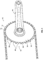
- numeral 10 generally indicates a conventional roller drive chain for a bicycle or any similar chain-driven device.
- the drive chain 10 generally includes outer chain links 12 and inner chain links 14 which are pivotally mounted on and connected to the outer chain links by pins 16, 18.
- the outer chain links 12 are alternatingly interleaved with the inner chain links 14.
- the outer chain links 12 have paired outer link plates 20 and the inner chain links have paired inner link plates 22.
- rollers 24 are arranged around the pins 16, 18.
- the plates 20, 22 are provided with holes 30 at their ends 32.
- the pins 16, 18 typically extend through and project out of the holes 30, although no projection at all is considered to be optimal.
- the pins 16, 18 are externally riveted at their ends 34, 36 during the assembly of the roller chain 10. While the pin 16 may be made of round stock, pin 18 may be made of tube stock, as in the roller chain 10 in FIG. 2 .
- a narrow middle part 38 which helps to determine the positioning of the roller chain 10 extends between the two circular ends 32 of each of the outer link plates 20 and the inner link plates 22.
- the interleaving of the outer links 12 and inner links 14 creates corresponding alternating outer link spaces 40 and inner links spaces 42.
- the outer link spaces 40 are openings defined by the outer link plates 20 and rollers 24.
- the inner link spaces 42 are openings defined by the inner link plates 22 and rollers 24.
- the inner link spaces 42 are generally rectangular with the long axis of the rectangle aligned with the long axis (A) of the chain 10 (as viewed as in FIG. 1 ).
- the axial length of the inner link spaces 42 is determined by the distance between the rollers 24, while the distance between the inner link plates 22 determines the transverse spacing of the inner link spaces.
- the outer link spaces 40 are generally in the shape of a "cross” or in other words, a "plus.”
- the axial length of the outer link spaces 40 is determined by the distance between the rollers 24, while the distance between the outer link plates 20 determines the transverse spacing of the outer link spaces.
- the transverse spacing between the outer link plates 20 is greater than the spacing between the inner link plates 22.
- the rollers dictate the transverse spacing D1 of the inner link spaces 42.
- the transverse spacing D2 of the outer link spaces 40 is dictated by the sum of the transverse width of the rollers 24 and the thickness of two inner link plates.
- a chainring 50 is used with a conventional chain 10.
- Chainrings typically have a large plurality of teeth compared to cassettes, for example, having about 20 or more teeth.
- a crank or crank arm 48 is in a typical position and attached to the chain ring 50 in a well-known manner.
- the crank side of the chainring 50 is shown in FIG. 3 , which is the outboard side 54 of the chainring.
- the outboard side also faces away from the vehicle to which it is attached.
- the opposite of the outboard side 54 of the chainring 50 is the inboard side 56.
- the inboard side 56 faces toward the vehicle.
- crank arm 48 typically in a downward direction, for example
- rotation of the chainring 50 in a like direction (clockwise).
- Rotation of the chainring 50 causes the chain 10 to be drawn over and advanced about the chainring.
- the chainring 50 has a plurality of teeth 52 formed about the periphery 51 of the chainring, with the total number of the plurality of teeth consisting of an even number.
- the plurality of teeth 52 include a first group of teeth 58 and a second group of teeth 60 arranged in an alternating fashion and wherein the first group of teeth is equal in number to the second group of teeth.
- the invention provides the first group of teeth 58, that is configured to be received by and fitted into the outer link spaces 40, and a second group of teeth 60 that is configured to be received by and fitted into the inner link spaces 42.
- the overall shape of the chainring periphery 51 may be generally circular or non-circular, that is elliptical, oval, polygon, or parabolic, for example. All of the examples of chainrings provided herein are shown with a circular periphery 51.
- Each of the first group of teeth 58 is configured to engage with the chain 10 via an outer link space 40.
- Each of the second group of teeth 60 is configured to engage with the chain 10 via an inner link space 42.
- each of the second group of teeth 60 has a shape which in a cross sectional view is generally rectangular, particularly at or near the base or root of the tooth.
- the cross sectional view is taken through a plane parallel to the top land 80 of the tooth and passing through the base circle position of the tooth, i.e., about halfway between the root circle and the outside circle.
- each of the second group of teeth 60 should closely match the configuration of each of the inner link spaces 42 ( FIG. 1 ).
- the cross section shown of each of the second group of teeth shows that the outboard side 54 is generally planar and the inboard side 56 is also generally planar.
- Each of the second group of teeth 60 may fill over about 75% of the axial distance D 1 of a corresponding space in the chain 10.
- each of the second group of teeth 60 may fill over about 80% of D 1 of a corresponding space in the chain 10. More preferably, each of the second group of teeth 60 may fill over about 85% of D 1 of a corresponding space in the chain 10.
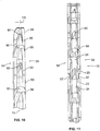
- each of the alternative versions of teeth 58a, 58b, 58c of the first group of teeth 58 has a shape which in a cross sectional view, taken through the tooth as in FIG. 12 , has the same longitudinal length L T as that of the second group of teeth 60 ( FIG. 12 ).
- Each of the first group of teeth 58 may fill over about 75% of the distance D 2 of a corresponding space in the chain 10.
- each of the first group of teeth 58 may fill over about 80% of D 2 of a corresponding space in the chain 10. More preferably, each of the first group of teeth 58 may fill over about 85% of D 2 of a corresponding space in the chain 10.
- Each of the first group of teeth 58 has the additional feature of an outboard or first protrusion 62 on the outboard side 54 of each alternative teeth 58a, 58b, and 58c.
- FIG. 13 also demonstrates that the inboard side 56 of tooth 58a can be the same (i.e., without a protrusion) as the inboard side 56 of each of the second group of teeth 60.
- the first protrusion 62 is configured to fit into the corresponding part of outer link spaces 40 of chain 10 ( FIG. 1 ) and has a width W 1 .
- the protrusion 62 functions to help maintain the chain 10 on the chainring 50 ( FIG. 3 ).
- the protrusion 62 causes an overall width WO 2 of each of teeth 58a to be greater than the overall width WO 1 of each of teeth 60 by the extent of protrusion 62.
- FIG. 14 is another embodiment of a tooth 58b of the first group of teeth 58.
- tooth 58b is similar to those of FIG. 13 , with the additional feature of an inboard or second protrusion 64 on the inboard side 56 of the tooth.
- the protrusion 64 has a width W 2 that is less than the width W 1 of the protrusion 62 of tooth 58a, or alternatively, greater than W 1 .
- the protrusions 62, 64 cause an overall width WO 3 of each of teeth 58b to be greater than the overall width WO 1 of each of teeth 60 by the extent of protrusions 62, 64. Furthermore, WO 3 is greater than WO 2 .
- FIG. 15 is yet another embodiment of a tooth 58c of the first group of teeth 58.
- tooth 58c is similar to that of FIG. 14 , with an inboard or second protrusion 66 on the inboard side 56 of the tooth.
- the protrusion 66 has a width W 1 that is equal to the width W 1 of the protrusion 62 of tooth 58a.
- the protrusions 62, 66 cause an overall width WO 4 of each of teeth 58c to be greater than the overall width WO 1 of each of teeth 60 by the extent of protrusions 62, 66.
- WO 4 is greater than WO 3 .
- the various configurations of the teeth 58 include protrusions that are positioned along the side or sides of each tooth in a position where they effectively function to assist in positioning the chain on the chainring 50, including positions that are adjacent or at the base of each tooth or higher on each tooth 58.
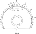
- FIG. 4 and FIG. 6 is an outboard side 54 of chainring 50 and the driving direction DD.
- the first group of teeth 58 is alternatingly arranged with the second group of teeth 60.
- the configuration of the second group of teeth 60 may be defined, with respect to the outboard and inboard sides 54, 56 of each of the teeth 60, by forming an inner link receiving recess 72 in the chainring 50 that represents material removed from the sides of the teeth 60.
- the inner link receiving recess 72 also serves to define the cross-sectional shape of each of the group of teeth 58.
- the inner link receiving recess 72 defines the outboard and inboard sides 54, 56 of each tooth and extends from the front flank 68 of one of the group of teeth 58 to a rear flank 70 of an adjacent one of the group of teeth 58 in the drive direction DD.
- Each inner link receiving recess 72 is configured to receive the length Lp an inner link plate 22 of the chain ( FIG. 6 ).
- Each recess 72 has a base surface 72a that extends in an axial direction and a wall 72b ( FIG. 7 ) that extends radially.
- the base surface 72a may describe a smoothly curving contour, and may be generally in the shape of a "U".
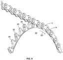
- FIG. 5 is the profile of each tooth of the teeth 58, 60 in more detail.
- the inner link receiving recess 72 is formed in the chainring 50 and can be seen extending along the side of each of the second group tooth 60 and extending from the load side, front or leading flank 68 of one of the group of teeth 58 to a rear flank 70 of an adjacent one of the group of teeth 58 in the drive direction DD.
- the recess 72 is configured to receive the length L P ( FIG. 6 ) of an inner link plate 22.
- Each tooth may have a top land 80.
- the base surface 72a may extend to the top land 80 of each of the teeth 58.
- the front flank 68 of each tooth includes a contact zone 74, where a roller 24 ( FIG. 1 ) contacts the tooth.
- the roller 24 does not contact the tip portion 76 under normal driving conditions.
- the tip portion 76 may protrude forwardly from a line drawn along the contact zone 74 a distance T.
- the protruding tip portion 76 functions to engage a chain link earlier than a chain lacking the tip portion and provides better guiding of the chain.
- An optional hook feature 78 is a feature that may be formed on the rear flank 70 of each of teeth 58, 60.
- the hook feature 78 is positioned along the rear flank 70 and may cooperate with the tip portion 76 to provide better guiding of the chain.
- the hook feature 78 may include a portion of the rear flank 70 being aligned in the radial direction R.
- each of the first group of teeth 58 and the second group of teeth 60 of the chainring 50 are arranged in an alternating fashion.
- An optional feature of each of the first group of teeth 58 and second group of teeth 60 is a respective outer chamfer 82a, 82b.
- Each of the first group of teeth 58 has an outer chamfer 82a, which may be an arcuate face formed on the outboard side 54 or shoulder of each tooth.
- Each of the second group of teeth 60 has an outer chamfer 82b, which may be an arcuate face formed on the outboard side 54 or shoulder of each tooth.
- the outer chamfer of 82b of each tooth 60 may have an extent C 1 that is greater relative to the extent C 2 of the outer chamfer 82a of each tooth 58.
- the chainring 50 includes chain 10 positioned and engaged thereon.
- Outer chain links 12 are positioned on the first group of teeth 58.
- Inner chain links 14 are positioned on the second group of teeth 60.
- FIGS. 10 and 11 respectively is a front view of the chainring 50 without a chain 10 and with a chain.
- An optional feature of all of the teeth 58, 60 of the chainring 50 is an offset OS of the center of the tooth tip or top land 80 from the center line CL in a direction toward the inboard side 56 of the chainring. This offset feature provides better guiding of the chain to one side of the chainring.
- a chainring 50 includes a number of teeth 58, 60.
- Link 1 of a chain engaged on the chainring 50 is represented by line L 1
- link 2 and link 3 are represented by lines L 2 , L 3 respectively.
- the line of each of L 1-3 is drawn between the centers of the axis of each of the chain rollers 24.
- the hook feature 78 is shown on the rear flank 70 of each of teeth 58, 60.
- the hook feature 78 is positioned along the rear flank 70 and may cooperate with the tip portion 76 of the front flank 68 to provide better guiding of the chain.
- the hook feature 78 may include a portion of the rear flank 70 being aligned in the radial direction R.
- the hook feature 78 has a radially outermost extent 78a where the hook feature and the link centerlines L 1-3 intersect. Alternately, the outermost extent 78a may be higher than the centerlines L 1-3 , providing more room for the roller to engage the teeth in the driving direction.
- the curved line 90 is the path of the roller 24 when it disengages the tooth.
- the chain 10 is installed with each of the outer chain links 12 on one of the first group of teeth 58 and each of the inner chain links 14 on one of the second group of teeth 60.
- the chainring 50 is rotated by the crank 48, the chain 10 is drawn about the chainring, and the outer chain links 12 and the inner chain links 14 are sequentially engaged with respective first and second ones of the groups of teeth 58, 60.
- the various features of the chainring 50 function to guide and maintain the chain 10 thereon. While this invention has been described by reference to particular embodiments, it should be understood that numerous changes could be made within the scope of the inventive concepts described. Accordingly, it is intended that the invention not be limited to the disclosed embodiments, but that it have the full scope permitted by the language of the following claims.
Landscapes
- Engineering & Computer Science (AREA)
- Mechanical Engineering (AREA)
- Chemical & Material Sciences (AREA)
- Combustion & Propulsion (AREA)
- Transportation (AREA)
- General Engineering & Computer Science (AREA)
- Devices For Conveying Motion By Means Of Endless Flexible Members (AREA)
- Gears, Cams (AREA)
- Automatic Cycles, And Cycles In General (AREA)
Claims (16)
- Einzelkettenring (50) einer Fahrradvorderkurbelanordnung zum Eingreifen in eine Antriebskette (10), umfassend:eine Mehrzahl von Zähnen (52), die an einem Umfang des Kettenrings (50) ausgebildet sind, wobei die Mehrzahl von Zähnen (52) aus einer geraden Anzahl besteht;wobei die Mehrzahl von Zähnen (52) eine erste Zahngruppe (58) und eine zweite Zahngruppe (60) umfasst, die abwechselnd zwischen der ersten Zahngruppe (58) angeordnet ist;wobei die erste Zahngruppe (58) und die zweite Zahngruppe (60) die gleiche Anzahl aufweisen,wobei jeder Zahn der ersten und zweiten Zahngruppen (58, 60) eine nach außen gerichtete Seite (54) und eine nach innen gerichtete Seite (56) entgegengesetzt zu der nach außen gerichteten Seite (54) umfasst,wobei jeder Zahn der ersten Zahngruppe (58) mindestens einen ersten Vorsprung auf der nach außen gerichteten Seite (54) desselben umfasst und jeder Zahn der zweiten Zahngruppe (60) ohne die ersten Vorsprünge auf der nach außen gerichteten Seite und der nach innen gerichteten Seite ausgebildet ist; undwobei der mindestens eine erste Vorsprung konfiguriert ist, um die Antriebskette (10) auf dem Kettenring (50) zu halten,dadurch gekennzeichnet, dass jede von der nach außen gerichteten Seite (54) und der nach innen gerichteten Seite (56) jedes Zahns der zweiten Zahngruppe (60) eine Kettengliedaufnahmevertiefung (72) definiert, die in dem Kettenring entlang jedes Zahns der zweiten Zahngruppe (60) ausgebildet ist, wobei jede Kettengliedaufnahmevertiefung (72) eine Basisfläche (72a), die sich in einer axialen Richtung erstreckt, und eine Wand (72b) aufweist, die sich in einer radialen Richtung erstreckt, wobei sich die Basisfläche (72a) bis zu einer oberen Fase (80) jedes Zahns der ersten Zahngruppe (58) erstreckt.
- Kettenring (50) nach Anspruch 1, ferner umfassend einen zweiten Vorsprung auf der nach innen gerichteten Seite (56) jedes Zahns der ersten Zahngruppe (58).
- Kettenring (50) nach Anspruch 2, wobei der erste Vorsprung eine erste Breite aufweist und der zweite Vorsprung eine zweite Breite aufweist, wobei die erste Breite gleich der zweiten Breite ist, oder wobei die erste Breite größer als die zweite Breite ist.
- Kettenring nach Anspruch 1, wobei sich jede Vertiefung von einer vorderen Flanke eines ersten Zahns der ersten Zahngruppe bis zu einer hinteren Flanke eines zweiten Zahns der ersten Zahngruppe erstreckt, wobei der erste Zahn und der zweite Zahn angrenzende Zähne der ersten Zahngruppe in einer Antriebsrichtung sind.
- Kettenring nach einem der Ansprüche 1 oder 4, ferner umfassend einen ersten Vorsprung auf der nach außen gerichteten Seite und einen zweiten Vorsprung auf der nach innen gerichteten Seite jedes Zahns der ersten Zahngruppe, wobei die ersten und zweiten Vorsprünge mindestens teilweise durch die Vertiefung definiert sind.
- Kettenring nach Anspruch 5, wobei der erste Vorsprung eine erste Breite aufweist und der zweite Vorsprung eine zweite Breite aufweist, wobei die erste Breite gleich der zweiten Breite ist, oder wobei die erste Breite größer als die zweite Breite ist.
- Kettenring nach einem der vorhergehenden Ansprüche, wobei die erste Zahngruppe (58) jeweils einen kreuzförmigen Querschnitt neben einer Basis derselben aufweist.
- Kettenring nach einem der vorhergehenden Ansprüche, wobei die zweite Zahngruppe (60) jeweils einen rechteckförmigen Querschnitt neben einer Basis derselben aufweist.
- Kettenring nach einem der vorhergehenden Ansprüche, wobei jeder Zahn der ersten Zahngruppe (58) und der zweiten Zahngruppe (60) eine vordere Flanke umfasst, und wobei die vordere Flanke einen vorstehenden Spitzenabschnitt umfasst, der konfiguriert ist, um die Kette zu führen.
- Kettenring nach einem der vorhergehenden Ansprüche, wobei jeder Zahn der ersten Zahngruppe und der zweiten Zahngruppe eine hintere Flanke umfasst, und wobei die hintere Flanke einen Hakenabschnitt umfasst, der konfiguriert ist, um die Kette zu führen.
- Kettenring nach Anspruch 10, wobei der Hakenabschnitt einen im Wesentlichen radial orientierten Abschnitt umfasst.
- Kettenring nach Anspruch 9, wobei der vorstehende Spitzenabschnitt und ein Hakenabschnitt eines angrenzenden Zahns zum Führen der Kette zusammenwirken.
- Kettenring nach einem der vorhergehenden Ansprüche, wobei jeder Zahn der ersten Zahngruppe eine radial äußere Abrundung umfasst, die eine erste Erstreckung entlang der nach außen gerichteten Seite jedes Zahns aufweist.
- Kettenring nach einem der vorhergehenden Ansprüche, wobei jeder Zahn der zweiten Zahngruppe eine radial äußere Abrundung umfasst, die eine zweite Erstreckung entlang der nach außen gerichteten Seite jedes Zahnes aufweist.
- Kettenring nach Anspruch 13 und 14, wobei jeder Zahn der ersten Zahngruppe eine äußere Abrundung umfasst, die eine erste Erstreckung aufweist, und jeder Zahn der zweiten Zahngruppe eine äußere Abrundung umfasst, die eine zweite Erstreckung aufweist, und wobei die erste Erstreckung kleiner als die zweite Erstreckung ist.
- Fahrradkurbelanordnung, umfassend:einen Fahrradkurbelarm; undeinen Einzelkettenring nach einem der vorhergehenden Ansprüche.
Priority Applications (7)
| Application Number | Priority Date | Filing Date | Title |
|---|---|---|---|
| EP16000934.6A EP3072800A1 (de) | 2011-12-06 | 2012-12-05 | Kettenrad |
| PL12008132T PL2602176T3 (pl) | 2011-12-06 | 2012-12-05 | Przednie koło łańcuchowe |
| EP16000933.8A EP3072799B1 (de) | 2011-12-06 | 2012-12-05 | Kettenrad |
| EP16000947.8A EP3072801A1 (de) | 2011-12-06 | 2012-12-05 | Kettenrad |
| EP16000950.2A EP3075644A1 (de) | 2011-12-06 | 2012-12-05 | Kettenrad |
| EP16000948.6A EP3072802B1 (de) | 2011-12-06 | 2012-12-05 | Kettenrad |
| EP16000949.4A EP3072803A1 (de) | 2011-12-06 | 2012-12-05 | Kettenrad |
Applications Claiming Priority (1)
| Application Number | Priority Date | Filing Date | Title |
|---|---|---|---|
| US13/311,735 US9182027B2 (en) | 2011-12-06 | 2011-12-06 | Chainring |
Related Child Applications (12)
| Application Number | Title | Priority Date | Filing Date |
|---|---|---|---|
| EP16000934.6A Division EP3072800A1 (de) | 2011-12-06 | 2012-12-05 | Kettenrad |
| EP16000934.6A Division-Into EP3072800A1 (de) | 2011-12-06 | 2012-12-05 | Kettenrad |
| EP16000933.8A Division-Into EP3072799B1 (de) | 2011-12-06 | 2012-12-05 | Kettenrad |
| EP16000933.8A Division EP3072799B1 (de) | 2011-12-06 | 2012-12-05 | Kettenrad |
| EP16000950.2A Division-Into EP3075644A1 (de) | 2011-12-06 | 2012-12-05 | Kettenrad |
| EP16000950.2A Division EP3075644A1 (de) | 2011-12-06 | 2012-12-05 | Kettenrad |
| EP16000949.4A Division EP3072803A1 (de) | 2011-12-06 | 2012-12-05 | Kettenrad |
| EP16000949.4A Division-Into EP3072803A1 (de) | 2011-12-06 | 2012-12-05 | Kettenrad |
| EP16000948.6A Division EP3072802B1 (de) | 2011-12-06 | 2012-12-05 | Kettenrad |
| EP16000948.6A Division-Into EP3072802B1 (de) | 2011-12-06 | 2012-12-05 | Kettenrad |
| EP16000947.8A Division EP3072801A1 (de) | 2011-12-06 | 2012-12-05 | Kettenrad |
| EP16000947.8A Division-Into EP3072801A1 (de) | 2011-12-06 | 2012-12-05 | Kettenrad |
Publications (2)
| Publication Number | Publication Date |
|---|---|
| EP2602176A1 EP2602176A1 (de) | 2013-06-12 |
| EP2602176B1 true EP2602176B1 (de) | 2018-03-28 |
Family
ID=47504563
Family Applications (7)
| Application Number | Title | Priority Date | Filing Date |
|---|---|---|---|
| EP16000949.4A Withdrawn EP3072803A1 (de) | 2011-12-06 | 2012-12-05 | Kettenrad |
| EP16000950.2A Pending EP3075644A1 (de) | 2011-12-06 | 2012-12-05 | Kettenrad |
| EP12008132.8A Active EP2602176B1 (de) | 2011-12-06 | 2012-12-05 | Kettenring |
| EP16000948.6A Active EP3072802B1 (de) | 2011-12-06 | 2012-12-05 | Kettenrad |
| EP16000934.6A Pending EP3072800A1 (de) | 2011-12-06 | 2012-12-05 | Kettenrad |
| EP16000947.8A Pending EP3072801A1 (de) | 2011-12-06 | 2012-12-05 | Kettenrad |
| EP16000933.8A Active EP3072799B1 (de) | 2011-12-06 | 2012-12-05 | Kettenrad |
Family Applications Before (2)
| Application Number | Title | Priority Date | Filing Date |
|---|---|---|---|
| EP16000949.4A Withdrawn EP3072803A1 (de) | 2011-12-06 | 2012-12-05 | Kettenrad |
| EP16000950.2A Pending EP3075644A1 (de) | 2011-12-06 | 2012-12-05 | Kettenrad |
Family Applications After (4)
| Application Number | Title | Priority Date | Filing Date |
|---|---|---|---|
| EP16000948.6A Active EP3072802B1 (de) | 2011-12-06 | 2012-12-05 | Kettenrad |
| EP16000934.6A Pending EP3072800A1 (de) | 2011-12-06 | 2012-12-05 | Kettenrad |
| EP16000947.8A Pending EP3072801A1 (de) | 2011-12-06 | 2012-12-05 | Kettenrad |
| EP16000933.8A Active EP3072799B1 (de) | 2011-12-06 | 2012-12-05 | Kettenrad |
Country Status (7)
| Country | Link |
|---|---|
| US (9) | US9182027B2 (de) |
| EP (7) | EP3072803A1 (de) |
| CN (7) | CN105857504B (de) |
| DE (10) | DE102012025875B3 (de) |
| ES (3) | ES2666831T3 (de) |
| PL (3) | PL2602176T3 (de) |
| TW (19) | TWM531534U (de) |
Families Citing this family (85)
| Publication number | Priority date | Publication date | Assignee | Title |
|---|---|---|---|---|
| US8820192B2 (en) | 2009-04-29 | 2014-09-02 | Race Face Prerformance Products Inc. | Bicycle crank arm and insert therefore |
| US9182027B2 (en) * | 2011-12-06 | 2015-11-10 | Sram, Llc | Chainring |
| US9062758B2 (en) * | 2011-12-06 | 2015-06-23 | Sram, Llc | Chainring |
| US9701364B2 (en) * | 2013-05-17 | 2017-07-11 | Shimano Inc. | Bicycle sprocket and bicycle crank assembly |
| DE102013009492B4 (de) * | 2013-06-05 | 2023-10-19 | Sram Deutschland Gmbh | Kettenring |
| US9150277B2 (en) * | 2014-01-07 | 2015-10-06 | Shimano Inc. | Bicycle crank assembly |
| US9086138B1 (en) * | 2014-01-14 | 2015-07-21 | Shimano Inc. | Bicycle sprocket |
| US10000256B2 (en) * | 2014-01-23 | 2018-06-19 | Shimano Inc. | Bicycle sprocket |
| DE102015000912B4 (de) | 2014-01-23 | 2024-02-22 | Shimano Inc. | Fahrradkettenblatt |
| US9394987B2 (en) * | 2014-02-10 | 2016-07-19 | Wolf Tooth Components, LLC | Sprocket |
| US9394986B2 (en) * | 2014-02-10 | 2016-07-19 | Wolf Tooth Components, LLC | Sprocket |
| US9581229B2 (en) * | 2014-02-10 | 2017-02-28 | Wolf Tooth Components, LLC | Sprocket |
| US9581230B2 (en) | 2014-02-10 | 2017-02-28 | Wolf Tooth Components, LLC | Sprocket |
| WO2015131023A1 (en) * | 2014-02-27 | 2015-09-03 | Eko Sport, Inc. | Alternating tooth chain ring |
| US9625027B2 (en) * | 2014-04-08 | 2017-04-18 | Wolf Tooth Components, LLC | Sprocket |
| US9404565B2 (en) * | 2014-04-08 | 2016-08-02 | Wolf Tooth Components, LLC | Sprocket |
| US9581231B2 (en) * | 2014-04-08 | 2017-02-28 | Wolf Tooth Components, LLC | Sprocket |
| US9409624B2 (en) * | 2014-04-11 | 2016-08-09 | Shimano Inc. | Bicycle sprocket |
| US9964196B2 (en) | 2014-05-20 | 2018-05-08 | Shimano Inc. | Bicycle sprocket |
| US20170191558A1 (en) * | 2014-05-29 | 2017-07-06 | Miranda & Irmaco, Lda. | Drivetrain system and use thereof |
| US9463844B2 (en) * | 2014-09-01 | 2016-10-11 | Shimano Inc. | Bicycle sprocket and bicycle sprocket assembly |
| US9334014B2 (en) * | 2014-09-01 | 2016-05-10 | Shimano Inc. | Bicycle sprocket and bicycle sprocket assembly |
| AU358118S (en) * | 2014-09-25 | 2014-10-13 | Calcino Corp Pty Ltd | A sprocket |
| DE102015219522A1 (de) * | 2014-10-14 | 2016-04-14 | Sram Deutschland Gmbh | Mehrfach-Kettenradanordnung für eine Hinterradnabe |
| USD750998S1 (en) * | 2014-12-19 | 2016-03-08 | John Wang | Sprocket |
| US9599208B2 (en) * | 2015-02-12 | 2017-03-21 | Sram, Llc | Chainrings and crank assemblies |
| US9631714B2 (en) | 2015-03-24 | 2017-04-25 | Shimano Inc. | Bicycle sprocket and bicycle crank assembly |
| USD774987S1 (en) * | 2015-04-01 | 2016-12-27 | Tien Hsin Industries Co., Ltd. | Bicycle sprocket |
| US10451166B2 (en) | 2015-04-13 | 2019-10-22 | Eko Sport, Inc. | Chain ring with teeth oppositely laterally engaging a drive chain |
| US9540070B2 (en) * | 2015-05-27 | 2017-01-10 | Shimano Inc. | Bicycle sprocket and bicycle crank assembly |
| DE102015008662A1 (de) | 2015-07-03 | 2017-01-05 | Sram Deutschland Gmbh | Einzelkettenrad für eine Fahrradvorderkurbelanordnung |
| US10703441B2 (en) | 2015-07-03 | 2020-07-07 | Sram Deutschland Gmbh | Drive arrangement for a bicycle |
| DE102015017347B3 (de) | 2015-07-03 | 2023-09-21 | Sram Deutschland Gmbh | Einzelkettenrad für eine Fahrradvorderkurbelanordnung |
| US9926038B2 (en) | 2015-07-28 | 2018-03-27 | Shimano Inc. | Bicycle sprocket, bicycle rear sprocket, and bicycle multiple sprocket assembly |
| US20170101159A1 (en) * | 2015-10-09 | 2017-04-13 | Shimano Inc. | Bicycle sprocket and bicycle sprocket assembly |
| JP2017071380A (ja) * | 2015-10-09 | 2017-04-13 | 株式会社シマノ | 自転車用スプロケット、及び自転車用スプロケット組立体 |
| DE102015016767A1 (de) | 2015-12-23 | 2017-06-29 | Sram Deutschland Gmbh | Antriebsanordnung eines Fahrrades mit einer Mehrfach-Kettenradanordnung |
| US10549816B2 (en) | 2016-02-26 | 2020-02-04 | Shimano Inc. | Bicycle sprocket and bicycle sprocket assembly |
| CN112517887A (zh) | 2016-04-11 | 2021-03-19 | 福克斯制造有限公司 | 用于形成自行车前链轮组件的方法 |
| EP3251938A1 (de) | 2016-06-03 | 2017-12-06 | ZUMA Innovation, S.L. | Kettenringsatz für ein kraftübertragungssystem mit segmentierten kettenringen auf verschiedenen ebenen |
| EP3251937A1 (de) | 2016-06-03 | 2017-12-06 | ZUMA Innovation, S.L. | Kettenringsatz für ein fahrradkraftübertragungssystem mit segmentiertem kettenring |
| EP3251940B1 (de) | 2016-06-03 | 2018-12-19 | ZUMA Innovation, S.L. | Kettenringsatz für ein kraftübertragungssystem |
| US10247291B2 (en) * | 2016-06-24 | 2019-04-02 | Shimano Inc. | Bicycle sprocket and bicycle sprocket assembly |
| US10359106B2 (en) | 2016-06-24 | 2019-07-23 | Shimano Inc. | Bicycle sprocket and bicycle sprocket assembly |
| US9885409B1 (en) | 2016-09-12 | 2018-02-06 | Shimano Inc. | Bicycle sprocket and bicycle rear sprocket assembly |
| US10138991B2 (en) * | 2016-09-14 | 2018-11-27 | Shimano Inc. | Bicycle sprocket |
| US9915336B1 (en) * | 2016-09-14 | 2018-03-13 | Shimano Inc. | Bicycle sprocket assembly |
| US10377445B2 (en) * | 2016-09-20 | 2019-08-13 | Shimano Inc. | Bicycle front sprocket assembly |
| US20170016524A1 (en) * | 2016-09-28 | 2017-01-19 | Chao-Yuan Cheng | Bicycle sprocket wheel |
| US10507888B2 (en) * | 2016-11-10 | 2019-12-17 | Shimano Inc. | Bicycle crank assembly and bicycle sprocket assembly |
| US10358186B2 (en) * | 2016-12-16 | 2019-07-23 | Shimano Inc. | Bicycle sprocket and bicycle sprocket assembly |
| DE102016015433A1 (de) * | 2016-12-23 | 2018-06-28 | Sram Deutschland Gmbh | Mehrfach-Ritzelanordnung und Fahrradantrieb mit einer solchen Mehrfach-Ritzelanordnung |
| US10577050B2 (en) * | 2016-12-26 | 2020-03-03 | Shimano Inc. | Bicycle sprocket |
| US10295041B2 (en) * | 2016-12-26 | 2019-05-21 | Shimano Inc. | Bicycle sprocket and bicycle sprocket assembly |
| TW201825811A (zh) | 2017-01-03 | 2018-07-16 | 榮輪科技股份有限公司 | 單一鏈輪的製造方法 |
| US10378637B2 (en) * | 2017-01-19 | 2019-08-13 | Shimano Inc. | Bicycle sprocket |
| CN108343708A (zh) * | 2017-01-23 | 2018-07-31 | 超汇桂盟传动(苏州)有限公司 | 链条及其内链片 |
| US10625821B2 (en) * | 2017-03-17 | 2020-04-21 | Shimano Inc. | Bicycle sprocket and bicycle sprocket assembly |
| JP2018179046A (ja) * | 2017-04-05 | 2018-11-15 | 株式会社シマノ | 自転車用スプロケットおよび自転車用スプロケットアッセンブリー |
| US10309515B2 (en) | 2017-04-17 | 2019-06-04 | Shimano Inc. | Bicycle rear sprocket |
| US10703439B2 (en) | 2017-04-20 | 2020-07-07 | Shimano Inc. | Bicycle sprocket |
| US11014628B2 (en) | 2017-04-28 | 2021-05-25 | Fox Factory, Inc. | Cinch direct mount 2X ring system |
| EP3831705B1 (de) | 2017-05-12 | 2024-02-14 | Miranda & Irmão Lda. | Kettenring mit schmalen und breiten zähnen |
| EP3406932A1 (de) | 2017-05-24 | 2018-11-28 | Miranda & Irmão Lda. | Antriebskette sowie verfahren zur herstellung einer antriebskette |
| CN112238920B (zh) * | 2017-05-30 | 2022-04-01 | 株式会社岛野 | 自行车链轮 |
| US10940916B2 (en) * | 2017-09-15 | 2021-03-09 | Shimano Inc. | Bicycle rear sprocket, bicycle rear sprocket assembly, and bicycle drive train |
| US10550925B2 (en) * | 2017-06-02 | 2020-02-04 | Shimano Inc. | Bicycle sprocket |
| US10378638B2 (en) * | 2017-06-15 | 2019-08-13 | Tien Hsin Industries Co., Ltd. | Bicycle sprocket |
| US10808824B2 (en) * | 2017-07-13 | 2020-10-20 | Shimano Inc. | Bicycle sprocket assembly |
| DE102017012035A1 (de) * | 2017-12-22 | 2019-06-27 | Sram Deutschland Gmbh | Einfach-Kettenrad |
| EP3831703B1 (de) * | 2018-02-28 | 2023-01-25 | SRAM Deutschland GmbH | Hinterrad-ritzelanordnung mit zwei einstückigen zur gemeinsamen drehung miteinander verbundenen teilanordnungen |
| US10865870B2 (en) * | 2018-07-06 | 2020-12-15 | Shimano Inc. | Bicycle sprocket |
| RU2692510C1 (ru) * | 2018-10-01 | 2019-06-25 | Артём Станиславович Усов | Пластинчатая цепь |
| US11300192B2 (en) * | 2018-11-28 | 2022-04-12 | D3 Innovation Inc. | Chainring for a bicycle |
| US11359709B2 (en) * | 2018-12-18 | 2022-06-14 | Fox Factory, Inc. | Chainring |
| US11767078B2 (en) * | 2019-02-05 | 2023-09-26 | Sram Deutschland Gmbh | Drive arrangement for a bicycle |
| TWI747152B (zh) * | 2019-02-05 | 2021-11-21 | 美商速聯有限責任公司 | 用於自行車的驅動配置 |
| US11680633B2 (en) | 2019-02-08 | 2023-06-20 | Fox Factory, Inc. | Chainring |
| DE102020211481A1 (de) * | 2019-10-08 | 2021-04-08 | Sram Deutschland Gmbh | Fahrradkette mit partiell reduzierter aussenkontur der innenlasche |
| DE202020000984U1 (de) | 2020-04-01 | 2020-04-15 | Sram Deutschland Gmbh | Schaltgassen an Mehrfachanordnungen von Kettenrädern |
| TWI726676B (zh) * | 2020-04-09 | 2021-05-01 | 傳誠技研有限公司 | 自行車鏈輪 |
| USD951819S1 (en) * | 2021-01-12 | 2022-05-17 | The Cycle Group | Cassette |
| USD951818S1 (en) * | 2021-01-12 | 2022-05-17 | The Cycle Group | Cassette |
| EP4239221B1 (de) * | 2022-03-03 | 2024-04-03 | Marcin Golec | Verbesserter fahrradkettenring und fahrrad mit diesem fahrradkettenring |
| JP2023173282A (ja) | 2022-05-25 | 2023-12-07 | 株式会社シマノ | ドライブトレイン |
Citations (8)
| Publication number | Priority date | Publication date | Assignee | Title |
|---|---|---|---|---|
| US4174642A (en) * | 1978-02-09 | 1979-11-20 | Gehl Company | Chain drive including sprocket having alternate wide and narrow teeth |
| JPS5642489U (de) * | 1979-09-08 | 1981-04-18 | ||
| JPS628181U (de) | 1985-07-01 | 1987-01-19 | ||
| US20020098934A1 (en) * | 2001-01-25 | 2002-07-25 | Wigsten Mark Macdonald | Sprocket system for inverted tooth chain |
| DE20317269U1 (de) | 2003-09-17 | 2004-11-18 | Wen, Yi-Ling, Feng Yuan | Kettenrad für ein Fahrrad |
| EP1489338A2 (de) | 2003-06-16 | 2004-12-22 | Sugino Cycle Industries, Ltd. | Rollenkettenrad |
| DE102006039333A1 (de) | 2005-09-07 | 2007-03-08 | Tsubakimoto Chain Co. | Gesintertes Kettenrad mit Vorsprüngen |
| US20110092327A1 (en) * | 2009-10-16 | 2011-04-21 | Shimano Inc. | Bicycle sprocket |
Family Cites Families (120)
| Publication number | Priority date | Publication date | Assignee | Title |
|---|---|---|---|---|
| US613756A (en) * | 1898-11-08 | Sprocket-wheel | ||
| US568862A (en) * | 1896-10-06 | Velocipede | ||
| US536813A (en) | 1895-04-02 | Sprocket-wheel | ||
| US515449A (en) * | 1894-02-27 | Bicycle | ||
| US513589A (en) * | 1894-01-30 | Bicycle | ||
| US528145A (en) * | 1894-10-30 | Bicycle | ||
| US530058A (en) * | 1894-11-27 | Driving-gear for bicycles | ||
| US581024A (en) | 1897-04-20 | Sprocket mechanism for bigycles | ||
| US611170A (en) | 1898-09-20 | James howard | ||
| US431529A (en) * | 1890-07-01 | Signments | ||
| US556254A (en) | 1896-03-10 | Charles w | ||
| US592552A (en) | 1897-10-26 | Drive-chain | ||
| US495584A (en) | 1893-04-18 | Herbert guthrie | ||
| US586991A (en) | 1897-07-27 | Drive-gear | ||
| US590649A (en) | 1897-09-28 | Sprocket wheel and chain | ||
| US591270A (en) | 1897-10-05 | Sprocket-wheel | ||
| US596289A (en) | 1897-12-28 | William thomas smith | ||
| US257445A (en) * | 1882-01-03 | 1882-05-02 | Francis m | |
| US702841A (en) * | 1901-06-25 | 1902-06-17 | William Frederick Williams | Elliptic chain driving-gear. |
| US1482896A (en) | 1919-08-20 | 1924-02-05 | Hiram H Huntington | Sprocket wheel |
| US1835406A (en) | 1922-05-16 | 1931-12-08 | Kirsten Boeing Engineering Co | Power transmitting mechanism |
| US2602343A (en) | 1949-11-26 | 1952-07-08 | Joy Mfg Co | Chain drive |
| GB825336A (en) | 1957-03-05 | 1959-12-16 | Juy Lucien Charles Hippolyte | Improvements in or relating to sprocket-wheels |
| US3375022A (en) | 1965-12-14 | 1968-03-26 | Green William P | Drives for bicycles |
| US3661021A (en) | 1969-07-26 | 1972-05-09 | Masakazu Ohshita Shimano Ind C | Multiple free wheel for a bicycle |
| US3648519A (en) | 1969-10-08 | 1972-03-14 | Kikunori Nakata | Multiple free wheel for a bicycle |
| JPS4980736A (de) | 1972-12-07 | 1974-08-03 | ||
| US3969947A (en) * | 1975-05-22 | 1976-07-20 | Gehl Company | Tapered tooth sprocket |
| US4144773A (en) * | 1976-07-12 | 1979-03-20 | Addicks Lyle F | Bicycle sprocket wheel |
| JPS53108054U (de) | 1977-02-05 | 1978-08-30 | ||
| JPS53165964U (de) | 1977-06-02 | 1978-12-26 | ||
| CA1064773A (en) | 1977-07-29 | 1979-10-23 | Lorne R. Shrum | Tank for explosive forming |
| US4268259A (en) | 1977-08-25 | 1981-05-19 | Shimano Industrial Company Limited | Multi-speed sprockets for a bicycle and the like |
| US4154327A (en) | 1977-10-31 | 1979-05-15 | Haeussinger John D | Convertible bicycle hub |
| DE2816137A1 (de) | 1978-04-14 | 1979-10-25 | Willi Strohmeyer Maschinenbau | Kettenrad |
| US4240303A (en) | 1978-09-27 | 1980-12-23 | Mosley Earnest D | Chain sprocket with opposite frangible side guide plates |
| JPS566698U (de) | 1979-06-28 | 1981-01-21 | ||
| JPS603269B2 (ja) * | 1979-09-14 | 1985-01-26 | 松下電工株式会社 | 多チヤンネルリモコンシステム |
| JPS6010955Y2 (ja) * | 1980-02-13 | 1985-04-12 | 株式会社シマノ | ギヤクランク装置 |
| EP0047092B1 (de) | 1980-08-18 | 1985-12-04 | Shimano Industrial Company Limited | Tretlager für Pedalfahrzeug |
| JPS628181Y2 (de) | 1980-10-17 | 1987-02-25 | ||
| JPS5890A (ja) | 1981-06-23 | 1983-01-05 | Kawasaki Heavy Ind Ltd | 金属水素化物を利用した熱交換器の構造 |
| JPS6015745Y2 (ja) | 1981-06-25 | 1985-05-17 | 株式会社杉野鉄工所 | スプロケツト |
| US4522610A (en) | 1982-06-01 | 1985-06-11 | Shimano Industrial Company Limited | Gear crank apparatus for a bicycle |
| JPS59153682A (ja) | 1983-02-19 | 1984-09-01 | 株式会社シマノ | 自転車用チエンギヤ |
| FR2545902B1 (fr) | 1983-05-13 | 1988-07-15 | Gauchon Ets Louis | Organe dente tournant pour systeme d'entrainement a chaine, et procede de fabrication |
| US4501575A (en) * | 1983-08-22 | 1985-02-26 | Lapeyre Fernand S | Multi-speed transmission for BMX bicycles and the like |
| JPS60104866U (ja) | 1983-12-20 | 1985-07-17 | 三菱電機株式会社 | 表示管保持片 |
| JPS6228128A (ja) | 1985-07-31 | 1987-02-06 | Shimano & Co Ltd | 楕円ギヤの製造法 |
| FR2588633A1 (fr) | 1985-10-14 | 1987-04-17 | Jouret Vanoverschelde | Roue dentee ainsi que son procede de fabrication |
| JPH0737388B2 (ja) | 1987-02-10 | 1995-04-26 | 田辺製薬株式会社 | 腎機能改善剤 |
| JPH01171795A (ja) | 1987-12-24 | 1989-07-06 | Daito Sanshin Kk | 切断機 |
| JPH02103890A (ja) | 1988-10-12 | 1990-04-16 | Sanyo Electric Co Ltd | 電子レンジ |
| JP2848834B2 (ja) | 1988-12-17 | 1999-01-20 | 株式会社シマノ | 自転車用多段ギヤクランク |
| FR2657134A1 (fr) | 1989-11-03 | 1991-07-19 | Sachs Ind Sa | Ensemble de pignons ou plateaux multiples pour cycle notamment. |
| JP3164805B2 (ja) | 1990-02-28 | 2001-05-14 | 株式会社シマノ | 自転車用多段スプロケット装置 |
| JPH04325390A (ja) | 1991-04-23 | 1992-11-13 | Maeda Kogyo Kk | 自転車用多段スプロケット装置 |
| FR2678890B3 (fr) | 1991-07-09 | 1993-10-15 | Bg Innovations | Roue dentee pour transmission par chaine, en particulier pour cycle. |
| FR2682349B1 (fr) * | 1991-10-11 | 1997-08-14 | Michel Sassi | Plateau non circulaire pour pedalier de bicyclette. |
| US5285701A (en) | 1992-05-26 | 1994-02-15 | Danial Parachinni | Gearing mechanism for high speed bicycles |
| JPH0740387A (ja) | 1993-07-27 | 1995-02-10 | Fanuc Ltd | 射出成形機用ノズル |
| US5609536A (en) * | 1995-06-13 | 1997-03-11 | Tracer Company, Ltd. | Bicycle freewheel gear cluster gear-shifting mechanism |
| US5759124A (en) | 1995-10-18 | 1998-06-02 | National Science Council | Multistage sprocket used in a bicycle rear derailleur system |
| DE19606667C2 (de) | 1996-02-23 | 1999-10-14 | Sram De Gmbh | Kettenschaltung für Fahrräder |
| US5921878A (en) | 1996-07-03 | 1999-07-13 | Cloyes Gear And Products, Inc. | Roller chain drive system having improved noise characteristics |
| JPH1026213A (ja) * | 1996-07-09 | 1998-01-27 | Tsubakimoto Chain Co | ローラチェーン用スプロケット歯形 |
| DE19628065C2 (de) | 1996-07-11 | 1998-06-04 | Daimler Benz Ag | Schutzeinrichtung für einen Türspalt eines gepanzerten Sonderschutzfahrzeuges |
| JP3533833B2 (ja) | 1996-07-24 | 2004-05-31 | 日産自動車株式会社 | ブレーキドラム構造 |
| US5921879A (en) * | 1996-07-25 | 1999-07-13 | Cloyes Gear And Products, Inc. | Random engagement roller chain sprocket with staged meshing and flank relief to provide improved noise characteristics |
| JP4061836B2 (ja) | 1996-08-14 | 2008-03-19 | サンスター技研株式会社 | スプロケット |
| DE69708118T2 (de) | 1996-08-14 | 2002-04-25 | Sunstar Engineering Inc | Kettenrad |
| US5672133A (en) * | 1996-10-09 | 1997-09-30 | Eden; Tom | Bicycle gearing system |
| US5921881A (en) * | 1996-11-21 | 1999-07-13 | Shimano, Inc. | Narrow bicycle chain with inner links that receive sprocket teeth within a bottom recess |
| DE29621084U1 (de) | 1996-12-04 | 1998-04-02 | Winklhofer & Soehne Gmbh | Kettenrad |
| US7416500B2 (en) * | 1996-12-19 | 2008-08-26 | Cloyes Gear And Products, Inc. | Random engagement roller chain sprocket and timing chain system including same |
| US6761657B2 (en) * | 1996-12-19 | 2004-07-13 | Cloyes Gear And Products, Inc. | Roller chain sprocket with added chordal pitch reduction |
| US5876159A (en) | 1997-04-23 | 1999-03-02 | Industrial Technology Research Institute | Sprocket trimming method for the multi-stage sprocket assembly |
| TW331290U (en) | 1997-08-01 | 1998-05-01 | Tracer Company Ltd | Improved structure of a chain wheel assembly of a bicycle |
| US6045472A (en) | 1997-12-30 | 2000-04-04 | National Science Council | Integrated up-and downshifting configuration of a multistage sprocket assembly for a bicycle |
| US6013001A (en) | 1998-02-04 | 2000-01-11 | Shimano, Inc. | Bicycle sprocket having recesses beneath chain receiving edges |
| US6152250A (en) * | 1998-07-07 | 2000-11-28 | Shu-Hsien; Li | Power driving control system of electrically-assisted bicycle |
| JP2000035049A (ja) | 1998-07-16 | 2000-02-02 | Nippon Seiko Kk | ユニバーサルジョイント |
| US6139456A (en) * | 1999-01-13 | 2000-10-31 | Lii; Jia-Miin | Bicycle sprocket |
| CN2366349Y (zh) * | 1999-03-25 | 2000-03-01 | 梁宗泰 | 自行车齿盘 |
| US6190275B1 (en) * | 1999-05-26 | 2001-02-20 | Gregory J. Ciancio | Bicycle chain anti-snare device |
| US6428437B1 (en) | 1999-06-10 | 2002-08-06 | Raphael Schlanger | Power transmission assembly |
| US6273836B1 (en) | 2000-02-11 | 2001-08-14 | Spencer J. Thompson | Chain sprocket with axial stiffeners |
| CN2430351Y (zh) * | 2000-07-18 | 2001-05-16 | 陈国钧 | 人力脚踏车辆传动装置 |
| US6340338B1 (en) | 2000-09-13 | 2002-01-22 | Shimano Inc. | Bicycle sprocket |
| US6666786B2 (en) | 2000-12-29 | 2003-12-23 | Shimano Inc. | Chamfered sprocket assembly |
| US7094170B2 (en) | 2002-05-06 | 2006-08-22 | Cloyes Gear And Products, Inc. | Cushioned sprocket and improved inverted tooth chain for use with same |
| US7128672B2 (en) * | 2003-04-16 | 2006-10-31 | Chalin Cluster Corporation | Cluster sprockets for bicycle transmissions and other prime movers |
| DE20314269U1 (de) | 2003-09-15 | 2003-12-18 | Pest, Stefan | Herz-Springform mit Einsätzen |
| DE10347784B4 (de) | 2003-10-10 | 2017-04-06 | Sram Deutschland Gmbh | Geräuscharme Kettenschaltung |
| JP2006007799A (ja) | 2004-06-22 | 2006-01-12 | Shimano Inc | 自転車用スプロケット |
| US7585240B2 (en) * | 2005-02-03 | 2009-09-08 | Shimano Inc. | Bicycle sprocket assembly |
| JP2006248290A (ja) | 2005-03-09 | 2006-09-21 | Shimano Inc | 自転車用スプロケット |
| ES2343971T3 (es) | 2005-03-15 | 2010-08-13 | Rotor Components Tecnologicos, S.L. | Plato ovoide para la optimizacion del pedaleo. |
| US7686721B2 (en) | 2005-05-11 | 2010-03-30 | Shimano Inc. | Bicycle chainring |
| US8617015B2 (en) * | 2005-09-27 | 2013-12-31 | Wick Werks, LLC | Bicycle chain rings |
| US8092329B2 (en) | 2005-08-31 | 2012-01-10 | Wick Werks, LLC | Bicycle chain rings with ramps |
| EP1764296B1 (de) | 2005-09-15 | 2012-05-30 | Campagnolo S.r.l. | Zahnrad von einem Fahrrad-Antriebsstrang |
| US7824287B2 (en) | 2005-12-02 | 2010-11-02 | Shimano Inc. | Bicycle sprocket |
| JP2007198403A (ja) | 2006-01-23 | 2007-08-09 | Toyota Motor Corp | 動力伝達装置 |
| DE102006022343B4 (de) | 2006-05-12 | 2010-04-15 | Shimano Inc., Sakai | Mehrkomponentenzahnrad |
| TW200846244A (en) * | 2007-05-30 | 2008-12-01 | Tian Hsin Inc Co Ltd | Structural improvement of chain wheel |
| CN201176245Y (zh) * | 2007-12-07 | 2009-01-07 | 重庆宗申技术开发研究有限公司 | 一种助力车二级传动装置 |
| TW201000360A (en) * | 2008-06-25 | 2010-01-01 | Tien Hsin Industries Co Ltd | Sprocket structure |
| US8550944B2 (en) * | 2008-10-01 | 2013-10-08 | Sram, Llc | Multi-speed sprocket assembly |
| JP5642489B2 (ja) | 2010-10-07 | 2014-12-17 | 日東電工株式会社 | 耐熱性低熱伝導発泡体 |
| WO2013027996A2 (ko) | 2011-08-23 | 2013-02-28 | Choi Yun Seok | 자전거의 비대칭 타원형상 체인기어 |
| JP2013096447A (ja) | 2011-10-28 | 2013-05-20 | Tsubakimoto Chain Co | スプロケットおよびチェーン伝動装置 |
| US9062758B2 (en) * | 2011-12-06 | 2015-06-23 | Sram, Llc | Chainring |
| US9182027B2 (en) | 2011-12-06 | 2015-11-10 | Sram, Llc | Chainring |
| JP2014088943A (ja) | 2012-10-31 | 2014-05-15 | Tsubakimoto Chain Co | スプロケット、チェーン伝動装置 |
| US9701364B2 (en) | 2013-05-17 | 2017-07-11 | Shimano Inc. | Bicycle sprocket and bicycle crank assembly |
| US9581230B2 (en) | 2014-02-10 | 2017-02-28 | Wolf Tooth Components, LLC | Sprocket |
| US9964196B2 (en) | 2014-05-20 | 2018-05-08 | Shimano Inc. | Bicycle sprocket |
| US10155566B2 (en) * | 2015-05-20 | 2018-12-18 | Shimano Inc. | Interchangeable bicycle sprocket |
| US9540070B2 (en) * | 2015-05-27 | 2017-01-10 | Shimano Inc. | Bicycle sprocket and bicycle crank assembly |
-
2011
- 2011-12-06 US US13/311,735 patent/US9182027B2/en active Active
-
2012
- 2012-10-26 TW TW105210193U patent/TWM531534U/zh unknown
- 2012-10-26 TW TW105113969A patent/TWI600852B/zh active
- 2012-10-26 TW TW105210196U patent/TWM534724U/zh unknown
- 2012-10-26 TW TW101139737A patent/TWI537501B/zh active
- 2012-10-26 TW TW105210192U patent/TWM546464U/zh unknown
- 2012-10-26 TW TW102137120A patent/TW201407068A/zh unknown
- 2012-10-26 TW TW105113972A patent/TWI599734B/zh not_active IP Right Cessation
- 2012-10-26 TW TW105113971A patent/TWI597441B/zh active
- 2012-10-26 TW TW105113975A patent/TWI585319B/zh active
- 2012-10-26 TW TW102223238U patent/TWM495449U/zh not_active IP Right Cessation
- 2012-10-26 TW TW108143118A patent/TWI744726B/zh active
- 2012-10-26 TW TW105210197U patent/TWM534722U/zh unknown
- 2012-10-26 TW TW106127973A patent/TWI679363B/zh active
- 2012-10-26 TW TW105113970A patent/TWI652199B/zh active
- 2012-10-26 TW TW105210194U patent/TWM531432U/zh unknown
- 2012-10-26 TW TW107113571A patent/TWI680245B/zh active
- 2012-10-26 TW TW105210198U patent/TWM534723U/zh unknown
- 2012-10-26 TW TW110136059A patent/TWI798844B/zh active
- 2012-10-26 TW TW105113968A patent/TWI583876B/zh active
- 2012-12-05 DE DE102012025875.5A patent/DE102012025875B3/de active Active
- 2012-12-05 ES ES12008132.8T patent/ES2666831T3/es active Active
- 2012-12-05 CN CN201610286246.9A patent/CN105857504B/zh active Active
- 2012-12-05 PL PL12008132T patent/PL2602176T3/pl unknown
- 2012-12-05 CN CN201210517493.7A patent/CN103144734B/zh active Active
- 2012-12-05 EP EP16000949.4A patent/EP3072803A1/de not_active Withdrawn
- 2012-12-05 EP EP16000950.2A patent/EP3075644A1/de active Pending
- 2012-12-05 EP EP12008132.8A patent/EP2602176B1/de active Active
- 2012-12-05 DE DE102012025876.3A patent/DE102012025876B3/de active Active
- 2012-12-05 DE DE102012023819.3A patent/DE102012023819B4/de active Active
- 2012-12-05 DE DE202012013379.9U patent/DE202012013379U1/de not_active Expired - Lifetime
- 2012-12-05 CN CN201610286224.2A patent/CN105947098B/zh active Active
- 2012-12-05 CN CN201610286306.7A patent/CN105752260B/zh active Active
- 2012-12-05 DE DE202012013381.0U patent/DE202012013381U1/de not_active Expired - Lifetime
- 2012-12-05 ES ES16000948T patent/ES2940913T3/es active Active
- 2012-12-05 EP EP16000948.6A patent/EP3072802B1/de active Active
- 2012-12-05 DE DE202012013376.4U patent/DE202012013376U1/de not_active Expired - Lifetime
- 2012-12-05 PL PL16000948.6T patent/PL3072802T3/pl unknown
- 2012-12-05 EP EP16000934.6A patent/EP3072800A1/de active Pending
- 2012-12-05 DE DE202012012533U patent/DE202012012533U1/de not_active Ceased
- 2012-12-05 EP EP16000947.8A patent/EP3072801A1/de active Pending
- 2012-12-05 PL PL16000933.8T patent/PL3072799T3/pl unknown
- 2012-12-05 CN CN201610286164.4A patent/CN105905228B/zh active Active
- 2012-12-05 ES ES16000933T patent/ES2964780T3/es active Active
- 2012-12-05 DE DE202012013378.0U patent/DE202012013378U1/de not_active Expired - Lifetime
- 2012-12-05 CN CN201610285783.1A patent/CN105905227B/zh active Active
- 2012-12-05 EP EP16000933.8A patent/EP3072799B1/de active Active
- 2012-12-05 CN CN201610286079.8A patent/CN105857503A/zh active Pending
- 2012-12-05 DE DE202012013380.2U patent/DE202012013380U1/de not_active Expired - Lifetime
- 2012-12-05 DE DE202012013377.2U patent/DE202012013377U1/de not_active Expired - Lifetime
-
2013
- 2013-10-31 US US29/471,384 patent/USD715699S1/en active Active
- 2013-12-10 US US14/102,013 patent/US9291250B2/en active Active
-
2015
- 2015-11-02 US US14/929,846 patent/US9650107B2/en active Active
- 2015-11-02 US US14/929,749 patent/US9862456B2/en active Active
- 2015-11-02 US US14/929,892 patent/US9731790B2/en active Active
- 2015-11-02 US US14/929,781 patent/US9493211B2/en active Active
-
2016
- 2016-01-11 US US14/992,270 patent/US9731791B2/en active Active
-
2017
- 2017-07-07 US US15/643,914 patent/US11110991B2/en active Active
Patent Citations (8)
| Publication number | Priority date | Publication date | Assignee | Title |
|---|---|---|---|---|
| US4174642A (en) * | 1978-02-09 | 1979-11-20 | Gehl Company | Chain drive including sprocket having alternate wide and narrow teeth |
| JPS5642489U (de) * | 1979-09-08 | 1981-04-18 | ||
| JPS628181U (de) | 1985-07-01 | 1987-01-19 | ||
| US20020098934A1 (en) * | 2001-01-25 | 2002-07-25 | Wigsten Mark Macdonald | Sprocket system for inverted tooth chain |
| EP1489338A2 (de) | 2003-06-16 | 2004-12-22 | Sugino Cycle Industries, Ltd. | Rollenkettenrad |
| DE20317269U1 (de) | 2003-09-17 | 2004-11-18 | Wen, Yi-Ling, Feng Yuan | Kettenrad für ein Fahrrad |
| DE102006039333A1 (de) | 2005-09-07 | 2007-03-08 | Tsubakimoto Chain Co. | Gesintertes Kettenrad mit Vorsprüngen |
| US20110092327A1 (en) * | 2009-10-16 | 2011-04-21 | Shimano Inc. | Bicycle sprocket |
Non-Patent Citations (8)
| Title |
|---|
| ANONYMOUS: "Sachs (Marke)", WIKIPEDIA, 7 February 2018 (2018-02-07), pages 1 - 4, XP055558085, Retrieved from the Internet <URL:https://de.wikipedia.org/w/index.php?title=Fichtel_%26_Sachs&oldid=173746414> |
| ANONYMOUS: "Saxonette (Motorfahrrad)", WIKIPEDIA, 29 October 2018 (2018-10-29), pages 1 - 2, XP055558098, Retrieved from the Internet <URL:https://de.wikipedia.org/w/index.php?title=Saxonette_(Motorfahrrad)&oldid=182272192> |
| ANONYMOUS: "SRAM XX1 prototype spotted - this one goes to 11", BIKERADAR, 28 May 2012 (2012-05-28), XP055558074, Retrieved from the Internet <URL:https://www.bikeradar.com/mtb/news/article/sram-xx1-prototype-spotted-this-one-goes-to-11-34098/> |
| JAMES HUANG: "SRAM XX1 - First ride review", BIKERADAR, 16 August 2012 (2012-08-16), XP055558075, Retrieved from the Internet <URL:https://www.bikeradar.com/mtb/gear/category/components/groupsets/groupset-mountain/product/review-sram-xx1-46487/> |
| NEIL SCLATER ET AL: "MECHANISMS AND MECHANICAL DEVICES SOURCEBOOK. 4th Ed.", 2007, MCGRAW-HILL, article "PULLEYS AND BELTS", pages: 14, XP055558115 |
| ROBERT E. GREEN ET AL: "25th ed. Machinery's Handbook. A REFERENCE BOOK FOR THE MECHANICAL ENGINEER, DESIGNER, MANUFACTURING ENGINEER, DRAFTSMAN, TOOLMAKER, AND MACHINIST", 1996, INDUSTRIAL PRESS INC., article "TRANSMISSION CHAINS", pages: 2337, XP055558110 |
| TOBIAS: "[Update) Vorstellung - SRAM XX1 - 11 Gänge ohne Kettenführung", MTB-NEWS, 2 July 2012 (2012-07-02), XP055558122, Retrieved from the Internet <URL:https://www.mtb-news.de/news/2012/07/02/vorstellung-sram-xx1-11-gaenge-ohne-kettenfuehrung/> |
| WINKLER F. ET AL: "Fahrad Technik", 1991, BIELEFELDER, ISBN: 3-87073·090-07, pages: 252, 258, XP055558104 |
Also Published As
Similar Documents
| Publication | Publication Date | Title |
|---|---|---|
| EP2602176B1 (de) | Kettenring | |
| US9062758B2 (en) | Chainring | |
| US10724621B2 (en) | Chainring | |
| EP1679255B1 (de) | Zahn eines Fahrradzahnrads | |
| EP3478561B1 (de) | Riemenantriebssystem | |
| TW202335900A (zh) | 腳踏車鏈環、腳踏車曲柄齒盤及腳踏車傳動系統 |
Legal Events
| Date | Code | Title | Description |
|---|---|---|---|
| REG | Reference to a national code |
Ref country code: DE Ref legal event code: R138 Ref document number: 202012013377 Country of ref document: DE Free format text: GERMAN DOCUMENT NUMBER IS 602012044394 |
|
| PUAI | Public reference made under article 153(3) epc to a published international application that has entered the european phase |
Free format text: ORIGINAL CODE: 0009012 |
|
| AK | Designated contracting states |
Kind code of ref document: A1 Designated state(s): AL AT BE BG CH CY CZ DE DK EE ES FI FR GB GR HR HU IE IS IT LI LT LU LV MC MK MT NL NO PL PT RO RS SE SI SK SM TR |
|
| AX | Request for extension of the european patent |
Extension state: BA ME |
|
| 17P | Request for examination filed |
Effective date: 20131204 |
|
| RBV | Designated contracting states (corrected) |
Designated state(s): AL AT BE BG CH CY CZ DE DK EE ES FI FR GB GR HR HU IE IS IT LI LT LU LV MC MK MT NL NO PL PT RO RS SE SI SK SM TR |
|
| TPAC | Observations filed by third parties |
Free format text: ORIGINAL CODE: EPIDOSNTIPA |
|
| 17Q | First examination report despatched |
Effective date: 20141103 |
|
| TPAC | Observations filed by third parties |
Free format text: ORIGINAL CODE: EPIDOSNTIPA |
|
| RAP1 | Party data changed (applicant data changed or rights of an application transferred) |
Owner name: SRAM, LLC. |
|
| RAP1 | Party data changed (applicant data changed or rights of an application transferred) |
Owner name: SRAM, LLC |
|
| TPAC | Observations filed by third parties |
Free format text: ORIGINAL CODE: EPIDOSNTIPA |
|
| GRAP | Despatch of communication of intention to grant a patent |
Free format text: ORIGINAL CODE: EPIDOSNIGR1 |
|
| STAA | Information on the status of an ep patent application or granted ep patent |
Free format text: STATUS: GRANT OF PATENT IS INTENDED |
|
| INTG | Intention to grant announced |
Effective date: 20171127 |
|
| TPAC | Observations filed by third parties |
Free format text: ORIGINAL CODE: EPIDOSNTIPA |
|
| GRAS | Grant fee paid |
Free format text: ORIGINAL CODE: EPIDOSNIGR3 |
|
| GRAJ | Information related to disapproval of communication of intention to grant by the applicant or resumption of examination proceedings by the epo deleted |
Free format text: ORIGINAL CODE: EPIDOSDIGR1 |
|
| GRAL | Information related to payment of fee for publishing/printing deleted |
Free format text: ORIGINAL CODE: EPIDOSDIGR3 |
|
| STAA | Information on the status of an ep patent application or granted ep patent |
Free format text: STATUS: EXAMINATION IS IN PROGRESS |
|
| GRAR | Information related to intention to grant a patent recorded |
Free format text: ORIGINAL CODE: EPIDOSNIGR71 |
|
| STAA | Information on the status of an ep patent application or granted ep patent |
Free format text: STATUS: GRANT OF PATENT IS INTENDED |
|
| GRAA | (expected) grant |
Free format text: ORIGINAL CODE: 0009210 |
|
| STAA | Information on the status of an ep patent application or granted ep patent |
Free format text: STATUS: THE PATENT HAS BEEN GRANTED |
|
| INTC | Intention to grant announced (deleted) | ||
| AK | Designated contracting states |
Kind code of ref document: B1 Designated state(s): AL AT BE BG CH CY CZ DE DK EE ES FI FR GB GR HR HU IE IS IT LI LT LU LV MC MK MT NL NO PL PT RO RS SE SI SK SM TR |
|
| INTG | Intention to grant announced |
Effective date: 20180216 |
|
| REG | Reference to a national code |
Ref country code: GB Ref legal event code: FG4D |
|
| REG | Reference to a national code |
Ref country code: CH Ref legal event code: EP |
|
| REG | Reference to a national code |
Ref country code: AT Ref legal event code: REF Ref document number: 983157 Country of ref document: AT Kind code of ref document: T Effective date: 20180415 |
|
| REG | Reference to a national code |
Ref country code: IE Ref legal event code: FG4D |
|
| REG | Reference to a national code |
Ref country code: DE Ref legal event code: R096 Ref document number: 602012044394 Country of ref document: DE |
|
| REG | Reference to a national code |
Ref country code: ES Ref legal event code: FG2A Ref document number: 2666831 Country of ref document: ES Kind code of ref document: T3 Effective date: 20180508 |
|
| REG | Reference to a national code |
Ref country code: NL Ref legal event code: FP |
|
| PG25 | Lapsed in a contracting state [announced via postgrant information from national office to epo] |
Ref country code: LT Free format text: LAPSE BECAUSE OF FAILURE TO SUBMIT A TRANSLATION OF THE DESCRIPTION OR TO PAY THE FEE WITHIN THE PRESCRIBED TIME-LIMIT Effective date: 20180328 Ref country code: HR Free format text: LAPSE BECAUSE OF FAILURE TO SUBMIT A TRANSLATION OF THE DESCRIPTION OR TO PAY THE FEE WITHIN THE PRESCRIBED TIME-LIMIT Effective date: 20180328 Ref country code: NO Free format text: LAPSE BECAUSE OF FAILURE TO SUBMIT A TRANSLATION OF THE DESCRIPTION OR TO PAY THE FEE WITHIN THE PRESCRIBED TIME-LIMIT Effective date: 20180628 Ref country code: FI Free format text: LAPSE BECAUSE OF FAILURE TO SUBMIT A TRANSLATION OF THE DESCRIPTION OR TO PAY THE FEE WITHIN THE PRESCRIBED TIME-LIMIT Effective date: 20180328 |
|
| REG | Reference to a national code |
Ref country code: LT Ref legal event code: MG4D |
|
| PG25 | Lapsed in a contracting state [announced via postgrant information from national office to epo] |
Ref country code: GR Free format text: LAPSE BECAUSE OF FAILURE TO SUBMIT A TRANSLATION OF THE DESCRIPTION OR TO PAY THE FEE WITHIN THE PRESCRIBED TIME-LIMIT Effective date: 20180629 Ref country code: SE Free format text: LAPSE BECAUSE OF FAILURE TO SUBMIT A TRANSLATION OF THE DESCRIPTION OR TO PAY THE FEE WITHIN THE PRESCRIBED TIME-LIMIT Effective date: 20180328 Ref country code: LV Free format text: LAPSE BECAUSE OF FAILURE TO SUBMIT A TRANSLATION OF THE DESCRIPTION OR TO PAY THE FEE WITHIN THE PRESCRIBED TIME-LIMIT Effective date: 20180328 Ref country code: BG Free format text: LAPSE BECAUSE OF FAILURE TO SUBMIT A TRANSLATION OF THE DESCRIPTION OR TO PAY THE FEE WITHIN THE PRESCRIBED TIME-LIMIT Effective date: 20180628 Ref country code: RS Free format text: LAPSE BECAUSE OF FAILURE TO SUBMIT A TRANSLATION OF THE DESCRIPTION OR TO PAY THE FEE WITHIN THE PRESCRIBED TIME-LIMIT Effective date: 20180328 |
|
| PG25 | Lapsed in a contracting state [announced via postgrant information from national office to epo] |
Ref country code: EE Free format text: LAPSE BECAUSE OF FAILURE TO SUBMIT A TRANSLATION OF THE DESCRIPTION OR TO PAY THE FEE WITHIN THE PRESCRIBED TIME-LIMIT Effective date: 20180328 Ref country code: AL Free format text: LAPSE BECAUSE OF FAILURE TO SUBMIT A TRANSLATION OF THE DESCRIPTION OR TO PAY THE FEE WITHIN THE PRESCRIBED TIME-LIMIT Effective date: 20180328 Ref country code: IT Free format text: LAPSE BECAUSE OF FAILURE TO SUBMIT A TRANSLATION OF THE DESCRIPTION OR TO PAY THE FEE WITHIN THE PRESCRIBED TIME-LIMIT Effective date: 20180328 Ref country code: RO Free format text: LAPSE BECAUSE OF FAILURE TO SUBMIT A TRANSLATION OF THE DESCRIPTION OR TO PAY THE FEE WITHIN THE PRESCRIBED TIME-LIMIT Effective date: 20180328 |
|
| PG25 | Lapsed in a contracting state [announced via postgrant information from national office to epo] |
Ref country code: CZ Free format text: LAPSE BECAUSE OF FAILURE TO SUBMIT A TRANSLATION OF THE DESCRIPTION OR TO PAY THE FEE WITHIN THE PRESCRIBED TIME-LIMIT Effective date: 20180328 Ref country code: SM Free format text: LAPSE BECAUSE OF FAILURE TO SUBMIT A TRANSLATION OF THE DESCRIPTION OR TO PAY THE FEE WITHIN THE PRESCRIBED TIME-LIMIT Effective date: 20180328 Ref country code: SK Free format text: LAPSE BECAUSE OF FAILURE TO SUBMIT A TRANSLATION OF THE DESCRIPTION OR TO PAY THE FEE WITHIN THE PRESCRIBED TIME-LIMIT Effective date: 20180328 |
|
| REG | Reference to a national code |
Ref country code: AT Ref legal event code: MK05 Ref document number: 983157 Country of ref document: AT Kind code of ref document: T Effective date: 20180328 |
|
| PG25 | Lapsed in a contracting state [announced via postgrant information from national office to epo] |
Ref country code: PT Free format text: LAPSE BECAUSE OF FAILURE TO SUBMIT A TRANSLATION OF THE DESCRIPTION OR TO PAY THE FEE WITHIN THE PRESCRIBED TIME-LIMIT Effective date: 20180730 |
|
| REG | Reference to a national code |
Ref country code: DE Ref legal event code: R026 Ref document number: 602012044394 Country of ref document: DE |
|
| PLBI | Opposition filed |
Free format text: ORIGINAL CODE: 0009260 |
|
| PLAX | Notice of opposition and request to file observation + time limit sent |
Free format text: ORIGINAL CODE: EPIDOSNOBS2 |
|
| PG25 | Lapsed in a contracting state [announced via postgrant information from national office to epo] |
Ref country code: DK Free format text: LAPSE BECAUSE OF FAILURE TO SUBMIT A TRANSLATION OF THE DESCRIPTION OR TO PAY THE FEE WITHIN THE PRESCRIBED TIME-LIMIT Effective date: 20180328 Ref country code: AT Free format text: LAPSE BECAUSE OF FAILURE TO SUBMIT A TRANSLATION OF THE DESCRIPTION OR TO PAY THE FEE WITHIN THE PRESCRIBED TIME-LIMIT Effective date: 20180328 |
|
| 26 | Opposition filed |
Opponent name: 1021039 B.C. LTD Effective date: 20190103 |
|
| PG25 | Lapsed in a contracting state [announced via postgrant information from national office to epo] |
Ref country code: SI Free format text: LAPSE BECAUSE OF FAILURE TO SUBMIT A TRANSLATION OF THE DESCRIPTION OR TO PAY THE FEE WITHIN THE PRESCRIBED TIME-LIMIT Effective date: 20180328 |
|
| PLBB | Reply of patent proprietor to notice(s) of opposition received |
Free format text: ORIGINAL CODE: EPIDOSNOBS3 |
|
| REG | Reference to a national code |
Ref country code: CH Ref legal event code: PL |
|
| PG25 | Lapsed in a contracting state [announced via postgrant information from national office to epo] |
Ref country code: LU Free format text: LAPSE BECAUSE OF NON-PAYMENT OF DUE FEES Effective date: 20181205 Ref country code: MC Free format text: LAPSE BECAUSE OF FAILURE TO SUBMIT A TRANSLATION OF THE DESCRIPTION OR TO PAY THE FEE WITHIN THE PRESCRIBED TIME-LIMIT Effective date: 20180328 |
|
| REG | Reference to a national code |
Ref country code: IE Ref legal event code: MM4A |
|
| REG | Reference to a national code |
Ref country code: BE Ref legal event code: MM Effective date: 20181231 |
|
| PG25 | Lapsed in a contracting state [announced via postgrant information from national office to epo] |
Ref country code: IE Free format text: LAPSE BECAUSE OF NON-PAYMENT OF DUE FEES Effective date: 20181205 |
|
| PG25 | Lapsed in a contracting state [announced via postgrant information from national office to epo] |
Ref country code: BE Free format text: LAPSE BECAUSE OF NON-PAYMENT OF DUE FEES Effective date: 20181231 |
|
| PG25 | Lapsed in a contracting state [announced via postgrant information from national office to epo] |
Ref country code: CH Free format text: LAPSE BECAUSE OF NON-PAYMENT OF DUE FEES Effective date: 20181231 Ref country code: LI Free format text: LAPSE BECAUSE OF NON-PAYMENT OF DUE FEES Effective date: 20181231 |
|
| PG25 | Lapsed in a contracting state [announced via postgrant information from national office to epo] |
Ref country code: MT Free format text: LAPSE BECAUSE OF NON-PAYMENT OF DUE FEES Effective date: 20181205 |
|
| PG25 | Lapsed in a contracting state [announced via postgrant information from national office to epo] |
Ref country code: TR Free format text: LAPSE BECAUSE OF FAILURE TO SUBMIT A TRANSLATION OF THE DESCRIPTION OR TO PAY THE FEE WITHIN THE PRESCRIBED TIME-LIMIT Effective date: 20180328 |
|
| PG25 | Lapsed in a contracting state [announced via postgrant information from national office to epo] |
Ref country code: MK Free format text: LAPSE BECAUSE OF NON-PAYMENT OF DUE FEES Effective date: 20180328 Ref country code: HU Free format text: LAPSE BECAUSE OF FAILURE TO SUBMIT A TRANSLATION OF THE DESCRIPTION OR TO PAY THE FEE WITHIN THE PRESCRIBED TIME-LIMIT; INVALID AB INITIO Effective date: 20121205 Ref country code: CY Free format text: LAPSE BECAUSE OF FAILURE TO SUBMIT A TRANSLATION OF THE DESCRIPTION OR TO PAY THE FEE WITHIN THE PRESCRIBED TIME-LIMIT Effective date: 20180328 |
|
| PG25 | Lapsed in a contracting state [announced via postgrant information from national office to epo] |
Ref country code: IS Free format text: LAPSE BECAUSE OF FAILURE TO SUBMIT A TRANSLATION OF THE DESCRIPTION OR TO PAY THE FEE WITHIN THE PRESCRIBED TIME-LIMIT Effective date: 20180728 |
|
| TPAA | Information related to observations by third parties modified |
Free format text: ORIGINAL CODE: EPIDOSCTIPA |
|
| PLCK | Communication despatched that opposition was rejected |
Free format text: ORIGINAL CODE: EPIDOSNREJ1 |
|
| APBM | Appeal reference recorded |
Free format text: ORIGINAL CODE: EPIDOSNREFNO |
|
| APBP | Date of receipt of notice of appeal recorded |
Free format text: ORIGINAL CODE: EPIDOSNNOA2O |
|
| APAH | Appeal reference modified |
Free format text: ORIGINAL CODE: EPIDOSCREFNO |
|
| APBQ | Date of receipt of statement of grounds of appeal recorded |
Free format text: ORIGINAL CODE: EPIDOSNNOA3O |
|
| REG | Reference to a national code |
Ref country code: DE Ref legal event code: R082 Ref document number: 602012044394 Country of ref document: DE Representative=s name: THUM, MOETSCH, WEICKERT PATENTANWAELTE PARTG M, DE Ref country code: DE Ref legal event code: R082 Ref document number: 602012044394 Country of ref document: DE Representative=s name: THUM & PARTNER THUM MOETSCH WEICKERT PATENTANW, DE |
|
| REG | Reference to a national code |
Ref country code: DE Ref legal event code: R100 Ref document number: 602012044394 Country of ref document: DE |
|
| APBU | Appeal procedure closed |
Free format text: ORIGINAL CODE: EPIDOSNNOA9O |
|
| PLBN | Opposition rejected |
Free format text: ORIGINAL CODE: 0009273 |
|
| STAA | Information on the status of an ep patent application or granted ep patent |
Free format text: STATUS: OPPOSITION REJECTED |
|
| 27O | Opposition rejected |
Effective date: 20211222 |
|
| PGFP | Annual fee paid to national office [announced via postgrant information from national office to epo] |
Ref country code: ES Payment date: 20230109 Year of fee payment: 11 |
|
| P01 | Opt-out of the competence of the unified patent court (upc) registered |
Effective date: 20230524 |
|
| PGFP | Annual fee paid to national office [announced via postgrant information from national office to epo] |
Ref country code: PL Payment date: 20230920 Year of fee payment: 12 |
|
| PGFP | Annual fee paid to national office [announced via postgrant information from national office to epo] |
Ref country code: NL Payment date: 20231110 Year of fee payment: 12 |
|
| PGFP | Annual fee paid to national office [announced via postgrant information from national office to epo] |
Ref country code: GB Payment date: 20231108 Year of fee payment: 12 |
|
| PGFP | Annual fee paid to national office [announced via postgrant information from national office to epo] |
Ref country code: FR Payment date: 20231108 Year of fee payment: 12 Ref country code: DE Payment date: 20231108 Year of fee payment: 12 |
|
| PGFP | Annual fee paid to national office [announced via postgrant information from national office to epo] |
Ref country code: ES Payment date: 20240109 Year of fee payment: 12 |