EP2600030A2 - Torque converter - Google Patents
Torque converter Download PDFInfo
- Publication number
- EP2600030A2 EP2600030A2 EP12007802.7A EP12007802A EP2600030A2 EP 2600030 A2 EP2600030 A2 EP 2600030A2 EP 12007802 A EP12007802 A EP 12007802A EP 2600030 A2 EP2600030 A2 EP 2600030A2
- Authority
- EP
- European Patent Office
- Prior art keywords
- torque converter
- torque
- flywheel
- spring
- springs
- Prior art date
- Legal status (The legal status is an assumption and is not a legal conclusion. Google has not performed a legal analysis and makes no representation as to the accuracy of the status listed.)
- Withdrawn
Links
Images


Classifications
-
- F—MECHANICAL ENGINEERING; LIGHTING; HEATING; WEAPONS; BLASTING
- F16—ENGINEERING ELEMENTS AND UNITS; GENERAL MEASURES FOR PRODUCING AND MAINTAINING EFFECTIVE FUNCTIONING OF MACHINES OR INSTALLATIONS; THERMAL INSULATION IN GENERAL
- F16F—SPRINGS; SHOCK-ABSORBERS; MEANS FOR DAMPING VIBRATION
- F16F15/00—Suppression of vibrations in systems; Means or arrangements for avoiding or reducing out-of-balance forces, e.g. due to motion
- F16F15/10—Suppression of vibrations in rotating systems by making use of members moving with the system
- F16F15/14—Suppression of vibrations in rotating systems by making use of members moving with the system using masses freely rotating with the system, i.e. uninvolved in transmitting driveline torque, e.g. rotative dynamic dampers
- F16F15/1407—Suppression of vibrations in rotating systems by making use of members moving with the system using masses freely rotating with the system, i.e. uninvolved in transmitting driveline torque, e.g. rotative dynamic dampers the rotation being limited with respect to the driving means
- F16F15/145—Masses mounted with play with respect to driving means thus enabling free movement over a limited range
-
- F—MECHANICAL ENGINEERING; LIGHTING; HEATING; WEAPONS; BLASTING
- F16—ENGINEERING ELEMENTS AND UNITS; GENERAL MEASURES FOR PRODUCING AND MAINTAINING EFFECTIVE FUNCTIONING OF MACHINES OR INSTALLATIONS; THERMAL INSULATION IN GENERAL
- F16F—SPRINGS; SHOCK-ABSORBERS; MEANS FOR DAMPING VIBRATION
- F16F15/00—Suppression of vibrations in systems; Means or arrangements for avoiding or reducing out-of-balance forces, e.g. due to motion
- F16F15/10—Suppression of vibrations in rotating systems by making use of members moving with the system
- F16F15/12—Suppression of vibrations in rotating systems by making use of members moving with the system using elastic members or friction-damping members, e.g. between a rotating shaft and a gyratory mass mounted thereon
- F16F15/131—Suppression of vibrations in rotating systems by making use of members moving with the system using elastic members or friction-damping members, e.g. between a rotating shaft and a gyratory mass mounted thereon the rotating system comprising two or more gyratory masses
- F16F15/133—Suppression of vibrations in rotating systems by making use of members moving with the system using elastic members or friction-damping members, e.g. between a rotating shaft and a gyratory mass mounted thereon the rotating system comprising two or more gyratory masses using springs as elastic members, e.g. metallic springs
- F16F15/134—Wound springs
- F16F15/13469—Combinations of dampers, e.g. with multiple plates, multiple spring sets, i.e. complex configurations
- F16F15/13476—Combinations of dampers, e.g. with multiple plates, multiple spring sets, i.e. complex configurations resulting in a staged spring characteristic, e.g. with multiple intermediate plates
-
- F—MECHANICAL ENGINEERING; LIGHTING; HEATING; WEAPONS; BLASTING
- F16—ENGINEERING ELEMENTS AND UNITS; GENERAL MEASURES FOR PRODUCING AND MAINTAINING EFFECTIVE FUNCTIONING OF MACHINES OR INSTALLATIONS; THERMAL INSULATION IN GENERAL
- F16F—SPRINGS; SHOCK-ABSORBERS; MEANS FOR DAMPING VIBRATION
- F16F15/00—Suppression of vibrations in systems; Means or arrangements for avoiding or reducing out-of-balance forces, e.g. due to motion
- F16F15/10—Suppression of vibrations in rotating systems by making use of members moving with the system
- F16F15/12—Suppression of vibrations in rotating systems by making use of members moving with the system using elastic members or friction-damping members, e.g. between a rotating shaft and a gyratory mass mounted thereon
- F16F15/131—Suppression of vibrations in rotating systems by making use of members moving with the system using elastic members or friction-damping members, e.g. between a rotating shaft and a gyratory mass mounted thereon the rotating system comprising two or more gyratory masses
- F16F15/139—Suppression of vibrations in rotating systems by making use of members moving with the system using elastic members or friction-damping members, e.g. between a rotating shaft and a gyratory mass mounted thereon the rotating system comprising two or more gyratory masses characterised by friction-damping means
-
- F—MECHANICAL ENGINEERING; LIGHTING; HEATING; WEAPONS; BLASTING
- F16—ENGINEERING ELEMENTS AND UNITS; GENERAL MEASURES FOR PRODUCING AND MAINTAINING EFFECTIVE FUNCTIONING OF MACHINES OR INSTALLATIONS; THERMAL INSULATION IN GENERAL
- F16H—GEARING
- F16H45/00—Combinations of fluid gearings for conveying rotary motion with couplings or clutches
- F16H45/02—Combinations of fluid gearings for conveying rotary motion with couplings or clutches with mechanical clutches for bridging a fluid gearing of the hydrokinetic type
-
- F—MECHANICAL ENGINEERING; LIGHTING; HEATING; WEAPONS; BLASTING
- F16—ENGINEERING ELEMENTS AND UNITS; GENERAL MEASURES FOR PRODUCING AND MAINTAINING EFFECTIVE FUNCTIONING OF MACHINES OR INSTALLATIONS; THERMAL INSULATION IN GENERAL
- F16H—GEARING
- F16H45/00—Combinations of fluid gearings for conveying rotary motion with couplings or clutches
- F16H2045/007—Combinations of fluid gearings for conveying rotary motion with couplings or clutches comprising a damper between turbine of the fluid gearing and the mechanical gearing unit
-
- F—MECHANICAL ENGINEERING; LIGHTING; HEATING; WEAPONS; BLASTING
- F16—ENGINEERING ELEMENTS AND UNITS; GENERAL MEASURES FOR PRODUCING AND MAINTAINING EFFECTIVE FUNCTIONING OF MACHINES OR INSTALLATIONS; THERMAL INSULATION IN GENERAL
- F16H—GEARING
- F16H45/00—Combinations of fluid gearings for conveying rotary motion with couplings or clutches
- F16H45/02—Combinations of fluid gearings for conveying rotary motion with couplings or clutches with mechanical clutches for bridging a fluid gearing of the hydrokinetic type
- F16H2045/021—Combinations of fluid gearings for conveying rotary motion with couplings or clutches with mechanical clutches for bridging a fluid gearing of the hydrokinetic type three chamber system, i.e. comprising a separated, closed chamber specially adapted for actuating a lock-up clutch
-
- F—MECHANICAL ENGINEERING; LIGHTING; HEATING; WEAPONS; BLASTING
- F16—ENGINEERING ELEMENTS AND UNITS; GENERAL MEASURES FOR PRODUCING AND MAINTAINING EFFECTIVE FUNCTIONING OF MACHINES OR INSTALLATIONS; THERMAL INSULATION IN GENERAL
- F16H—GEARING
- F16H45/00—Combinations of fluid gearings for conveying rotary motion with couplings or clutches
- F16H45/02—Combinations of fluid gearings for conveying rotary motion with couplings or clutches with mechanical clutches for bridging a fluid gearing of the hydrokinetic type
- F16H2045/0221—Combinations of fluid gearings for conveying rotary motion with couplings or clutches with mechanical clutches for bridging a fluid gearing of the hydrokinetic type with damping means
- F16H2045/0226—Combinations of fluid gearings for conveying rotary motion with couplings or clutches with mechanical clutches for bridging a fluid gearing of the hydrokinetic type with damping means comprising two or more vibration dampers
-
- F—MECHANICAL ENGINEERING; LIGHTING; HEATING; WEAPONS; BLASTING
- F16—ENGINEERING ELEMENTS AND UNITS; GENERAL MEASURES FOR PRODUCING AND MAINTAINING EFFECTIVE FUNCTIONING OF MACHINES OR INSTALLATIONS; THERMAL INSULATION IN GENERAL
- F16H—GEARING
- F16H45/00—Combinations of fluid gearings for conveying rotary motion with couplings or clutches
- F16H45/02—Combinations of fluid gearings for conveying rotary motion with couplings or clutches with mechanical clutches for bridging a fluid gearing of the hydrokinetic type
- F16H2045/0221—Combinations of fluid gearings for conveying rotary motion with couplings or clutches with mechanical clutches for bridging a fluid gearing of the hydrokinetic type with damping means
- F16H2045/0252—Combinations of fluid gearings for conveying rotary motion with couplings or clutches with mechanical clutches for bridging a fluid gearing of the hydrokinetic type with damping means having a damper arranged on input side of the lock-up clutch
-
- F—MECHANICAL ENGINEERING; LIGHTING; HEATING; WEAPONS; BLASTING
- F16—ENGINEERING ELEMENTS AND UNITS; GENERAL MEASURES FOR PRODUCING AND MAINTAINING EFFECTIVE FUNCTIONING OF MACHINES OR INSTALLATIONS; THERMAL INSULATION IN GENERAL
- F16H—GEARING
- F16H45/00—Combinations of fluid gearings for conveying rotary motion with couplings or clutches
- F16H45/02—Combinations of fluid gearings for conveying rotary motion with couplings or clutches with mechanical clutches for bridging a fluid gearing of the hydrokinetic type
- F16H2045/0221—Combinations of fluid gearings for conveying rotary motion with couplings or clutches with mechanical clutches for bridging a fluid gearing of the hydrokinetic type with damping means
- F16H2045/0263—Combinations of fluid gearings for conveying rotary motion with couplings or clutches with mechanical clutches for bridging a fluid gearing of the hydrokinetic type with damping means the damper comprising a pendulum
-
- F—MECHANICAL ENGINEERING; LIGHTING; HEATING; WEAPONS; BLASTING
- F16—ENGINEERING ELEMENTS AND UNITS; GENERAL MEASURES FOR PRODUCING AND MAINTAINING EFFECTIVE FUNCTIONING OF MACHINES OR INSTALLATIONS; THERMAL INSULATION IN GENERAL
- F16H—GEARING
- F16H45/00—Combinations of fluid gearings for conveying rotary motion with couplings or clutches
- F16H45/02—Combinations of fluid gearings for conveying rotary motion with couplings or clutches with mechanical clutches for bridging a fluid gearing of the hydrokinetic type
- F16H2045/0273—Combinations of fluid gearings for conveying rotary motion with couplings or clutches with mechanical clutches for bridging a fluid gearing of the hydrokinetic type characterised by the type of the friction surface of the lock-up clutch
- F16H2045/0284—Multiple disk type lock-up clutch
Definitions
- the invention relates to a torque converter.
- the invention relates to a torque converter with a two-mass flywheel.
- a torque converter For transmitting torque from a drive motor to a transmission in a motor vehicle, a torque converter can be used.
- the torque converter comprises a turbine having an impeller and a turbine wheel, which are at least partially surrounded by a liquid, so that the rotating impeller drives the turbine wheel.
- a converter clutch is additionally provided in order to mechanically couple the movement of the turbine wheel to that of the impeller, if required.
- the torque transmission takes place, for example, during a starting process of the motor vehicle by the hydrodynamic coupling by means of the turbine and during a normal driving operation by the mechanical coupling by means of the converter clutch.
- A1 Proposes to fix the centrifugal pendulum on the turbine wheel and to provide a lockup clutch for bridging the turbine during load operation.
- a first torsional damper introduces torque from the turbine to the output shaft and a second torsional damper introduces torque from the lockup clutch to the output shaft.
- the second torsion damper consists of two torsion damper elements, which are arranged in series. The arrangement of the damper elements should help to minimize the space requirement of the described torque converter.
- Torque transducers of the type described basically represent a torsional vibration system, which can be put into a torsional vibration (torsional vibration), for example, by rotational irregularities of an engine driving the drive shaft.
- a two-mass flywheel may be used.
- the two-mass flywheel can create new vibration problems in certain operating conditions.
- the invention is therefore based on the object to provide a torque converter with a two-mass flywheel, which realizes an improved isolation of torsional vibrations between the input and the output shaft.
- a torque converter for transmitting torque between an input side and an output side comprises a two-mass flywheel having a first rotatable flywheel, which is connected by means of an energy storage system with a second rotatable flywheel, connected to the output side further energy storage system, a turbine assembly and a Coupling unit, which are connected in parallel to each other, and a centrifugal pendulum for the eradication of torsional vibrations.
- the two-mass flywheel is arranged between the input side and the turbine arrangement or the coupling unit.
- the two-mass flywheel can transmit power between the input side and the turbine assembly or the clutch unit.
- the two-mass flywheel is arranged parallel to the turbine arrangement or the coupling unit.
- a first rotatable element and a second element rotatable coaxially thereto may be provided, wherein the first element is adapted to transmit torque between the input side and the output side and the second element is elastically rotatably coupled to the first element.
- the second element may, for example, comprise a part of the turbine arrangement, in particular the turbine wheel, so that it is possible to speak of a turbine filter.
- an already existing rotatable mass can advantageously be used for damping or eradicating torsional vibrations, so that a torsional vibration damper is formed, which is effective in particular in an operating state in which the coupling unit is closed and the turbine unit transmits only little or no torque ,
- This operating state may correspond to normal operation, which is predominantly used, so that the damping or eradication in another, less frequently used or less important operating state can be dispensed with.
- a further centrifugal pendulum can be mounted on a rotatable element which is coupled with a rotational movement of the input side or the output side.
- the further centrifugal pendulum for example, torsional vibrations, which are due to vibrations of the same fundamental frequency but different order, can be selectively isolated.
- At least one of the energy storage devices may include a plurality of springs distributed around a circumference about the direction of the torque. This is called a division of the energy storage or spring system. It is customary to divide into two to four feathers on one circumference.
- One or more energy stores may include a plurality of springs arranged such that a spring characteristic of the energy store comprises two or more different sections.
- the arrangement may therefore have different spring characteristics in sections over the spring travel, in particular differently steeply. This is referred to as a two-stage or multi-stage design of the arrangement.
- the multi-stage can be realized in another embodiment by only one coil spring, which in a first section is wound at a close distance between the turns and in a second section with a long distance between the turns. If this spring is compressed beyond a predetermined path, the turns of the tightly wound section abut each other and only the second section of the spring acts elastically.
- Torsional vibrations which occur, for example, in different operating states of an internal combustion engine driving the drive shaft can be degraded in an improved manner by means of the multistage spring system. Resonance effects of the spring system can be suppressed.
- One of the energy storage devices may comprise an arrangement of two parallel springs. By using springs with different spring characteristics, natural frequencies of the spring system can be weakened.
- One of the energy storage devices can also comprise an arrangement of two springs arranged in series. Between the springs, a flywheel can be arranged. Spring and damping characteristics of the different springs of the serial spring system can be equal or deliberately unequal selected to tune the vibration of the spring system to the degraded torsional vibrations.
- the energy storage can be at the same or different effective radii with respect to the torque.
- the dimensioning of the springs can be effected as a function of the effective radius.
- such an available space in the torque converter can be used improved.
- each of the springs may be a compression spring or a bow spring.
- the bow spring essentially follows a circumferential line about the axis of rotation, while the compression spring is substantially straight.
- a natural frequency of the centrifugal pendulum may correspond to a torsional vibration of a predetermined order of the input side.
- the centrifugal pendulum can be selectively adapted to the fundamental vibration or a corresponding higher-order vibration expected at the drive shaft.
- At least one of the energy-storing spring systems may be configured to be twisted no more than a predetermined angle.
- the restriction can be made, for example, by designing a spring whose turns rest on each other at a compression corresponding to the predetermined angle.
- a stop, a link or a bolt serve the purpose of the spring travel restriction.
- one of the energy-storing spring systems may include at least one friction element for generating a predetermined friction during rebounding.
- the friction can help to change a damping behavior of the spring system.
- the friction element may comprise, for example, a plate spring.
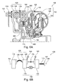
- FIGS. 1 to 7 an embodiment of a torque converter is shown, wherein a representation provided with the letter A represents a respective longitudinal section through the torque converter and provided with the letter B representation of a functional diagram of the torque flow.
- a representation provided with the letter A represents a respective longitudinal section through the torque converter and provided with the letter B representation of a functional diagram of the torque flow.
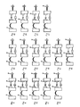
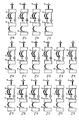
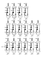
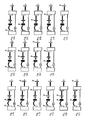
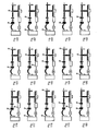
- FIGS. 8 to 193 show further embodiments of the torque converter of FIGS. 1 to 7 in the representation of the functional diagrams of the representations provided with the letter B FIGS. 1 to 7 ,
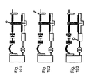
- FIG. 1 shows a first embodiment of a torque converter 100 for transmitting a torque.
- the torque converter 100 is in particular configured to transmit a torque which is output by an internal combustion engine, in particular a reciprocating piston engine, to a transmission.
- the engine, the torque converter 100, and the transmission are part of a powertrain of a motor vehicle, preferably a passenger car.
- FIG. 1A shows a sectional view of the upper half of the torque converter 100, while the lower part shown FIG. 1B a schematic power flow diagram of the torque converter Figure 1A represents.
- the operation of the torque converter 100 will be explained by assuming a torque flux from left to right, respectively. When operating as in a motor vehicle, this corresponds to the preferred Direction of torque flow. However, the reverse flow may also occur, for example, when a drag torque of the drive motor is used to decelerate the motor vehicle.
- An input side of the torque converter 100 is formed by an input shaft 105 or a driver 110, via which torque is coupled into the torque converter 100.
- a first flywheel 115 is connected rigidly to the input shaft 105 or to the driver 110.
- the first flywheel 115 can be, for example, a cast element or a metal sheet shaped accordingly, for example, by deep drawing, embossing or folding.
- a bow spring 120 serves as an energy storage system and couples the first flywheel 115 mechanically with a second flywheel 125, whereby a two-mass flywheel is formed.
- the bow spring 120 is curved along a circumference around the input shaft 105.
- Opposite ends of the bow spring 120 are connected to the first flywheel 115 and the second flywheel 125, respectively, so that a torque introduced via the input shaft 105 causes a force which tends to compress the bow spring 120.
- the bow spring 120 is supported on the second flywheel 115 and endeavors to set the second flywheel 125 in rotation.
- the second flywheel 125 is formed by a housing 128 which encloses the parts of the torque converter 100 described below and is at least partially filled with a liquid, in particular oil.
- the second flywheel 125 may also be configured separately from the housing 128. In this case, the second flywheel 125 may be inside or outside the housing 128.
- the housing 128 is rigidly connected to a pump wheel 135, the mass of which can thus be counted to the second flywheel 125.
- torque can be transmitted from the impeller 135 to a turbine 140.
- a stator 145 is arranged for producing predetermined flow conditions.
- the impeller 135, the turbine 140 and the stator 145 form a turbine assembly 150.
- the stator 145 is in FIG. 1B not shown.
- the two half-moons between the impeller 135 and the turbine 140 indicate a hydrostatic or hydrodynamic power transmission through the turbine assembly 150.
- a flange 155 is attached in a near-vicinity region of the turbine wheel 140.
- a centrifugal pendulum 160 is movably mounted in an outer region of the flange 155.
- centrifugal pendulums 160 are preferably evenly distributed over a circumference of the flange 155.
- Each centrifugal pendulum 160 includes two mass members that face each other with respect to the flange 155.
- the mass elements are preferably congruent or mutually symmetrical and connected to each other by means of one or more bolts.
- the bolt passes through a recess in the flange 155, wherein the recess in the plane of rotation is elongated, so that the mass elements of the centrifugal pendulum pendulum 160 are slidably mounted on the flange 155 in the manner of a slotted guide.
- a sleeve or other rolling element can be arranged as a rotary bearing about the bolt to facilitate the sliding movement of the pendulum mass relative to the flange 155.
- the centrifugal pendulum 160 may be mounted unifilar or bifilar depending on the number of bolts and the shape of the corresponding recesses in the flange 155, so that the centrifugal pendulum 160 can be rotated about a pivot point on the flange 155 or pivoted as trapezoidal pendulum in addition to its own axis, if a rotational acceleration or - delay on the flange 155 acts.
- the shape of the recesses on the flange 155 is suitably shaped for the respective movement. The movement of the centrifugal force pendulum 160 reduces or eliminates torsional vibrations of the flange 155.
- one of the recesses in the flange 155 may also be shaped such that in a portion of the possible movement of the bolt relative to the flange 155 there is a clearance that allows further tilting of the centrifugal force pendulum 160. As a result, for example, collisions between adjacent centrifugal force adjunct 160 can be avoided.
- a second flange 165 is firmly connected. Although the mass of the second flange 165 is usually is relatively small, it is part of the second flywheel 125.
- the clutch unit 170 includes a number of friction plates and vanes that can be pressed together to transmit torque between the flanges 155 and 165 in the axial direction.
- the coupling means 170 is within the housing 128 and can be lapped by the liquid; it is thus a wet clutch.
- the coupling unit 170 may also be located outside the housing 128 and the coupling unit 170 may be a dry clutch.
- the turbine wheel 140 and the elements fixedly connected thereto may be driven by a first torque flow passing through the turbine assembly 150 and / or by a second torque flow passing through the clutch unit 170.
- the coupling unit 170 is opened when the turbine wheel 140 is running slowly relative to the housing 128 or is stationary. If there is a sufficiently large speed difference between the turbine wheel 140 and the impeller 135 that can be driven by the drive shaft 105, a torque is transmitted through the turbine assembly 150. To avoid conversion losses within the turbine assembly 150, the coupling unit 170 may be closed. This is usually done when the turbine 140 has reached a sufficiently high rotational speed relative to the housing 128.
- the transmitted torque is decoupled by means of a compression spring 175 and forwarded to a third flange 180, which is connected to the output shaft 185.
- the compression spring 175 lies flush with its ends in two windows which are provided in the third flange 180 and a further flange which is connected to the first flange 155.
- the first flange 115 and the third flange 180 can be rotated forward or backward about the rotational axis of the torque converter 100, each compressing the compression spring 175.
- the compression spring 175 acts as another energy storage system.
- the flanges are each formed so that the compression spring 175 is supported in the axial direction.
- the output shaft 185 is a hollow shaft forming an output side of the torque converter 100.
- a solid shaft or a corresponding flange or driver may be provided for this purpose.
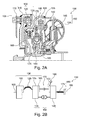
- FIG. 2 shows another embodiment of the torque converter 100 from FIG. 1 ,
- the illustrated embodiment differs essentially by the shape of the first flywheel 115 of the in FIG. 1 illustrated embodiment.
- the schematic diagram in FIG. 2B corresponds to that of FIG. 1B ,
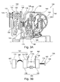
- FIG. 3 shows still another embodiment of the torque converter 100.
- a second centrifugal pendulum 190 is connected to the second flywheel 125.
- the second flywheel 190 is disposed outside of the housing 128 and thus runs dry; however, in another embodiment, the second centrifugal pendulum 190 may also be disposed within the housing 128.
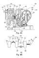
- FIG. 4 shows a further embodiment of the torque converter 100, which of the embodiment of FIG. 3 corresponds, with the difference that the first centrifugal pendulum 160 is omitted.
- the corresponding installation space is replaced by a mass element, which is formed on the first flange 155.
- the mass element is rotationally deflected relative to the coupling unit 170 during a rotational acceleration, the compression spring 175 being compressed.
- the compression spring 175 resets the mass element with respect to the coupling unit 170, as a result of which the energy stored in the mass element or in the compression spring 175 is converted back into a rotational movement.
- a reduction in the amplitude of the torsional vibrations can be achieved.
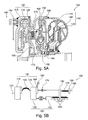
- FIG. 5 shows a further embodiment of the torque converter 100 of FIGS. 1 to 4 , As in the embodiment of FIG. 4 is attached to the second flywheel 135 second centrifugal pendulum 190 is provided while the turbine 140 carries no centrifugal pendulum. In contrast to FIG. 4 is at a third flange 192, the torque transmitted between the coupling unit 170 and the compression spring 175, connected by means of a double spring 195, the turbine 140 of the turbine assembly 150. As a result, the flywheel of the turbine wheel 140 can be used as a resiliently coupled damping mass. Such an arrangement is also called Turbin turbine.
- the double spring 195 may comprise a system of a plurality of springs, in particular a plurality of compressive bow springs, which allow the turbine wheel 140 to deflect with respect to the third flange 192 in both directions of rotation.
- the double spring 195 also include a system of a tension and a compression spring or a combined tension-compression spring.
- FIG. 6 shows a further embodiment of the torque converter 100 of FIGS. 1 to 5 ,
- the illustrated embodiment substantially corresponds to the embodiment of FIG. 3 with the difference that the second centrifugal pendulum 190 is mounted dry on the outside of the housing 128.
- FIG. 7 shows yet another embodiment of the torque converter 100 of FIGS. 1 to 6 , The embodiment shown corresponds to that of FIG. 3 with the difference that an additional bow spring 198 is provided to couple the coupling unit 170 with the turbine wheel 140.
- FIGS. 8 to 193 use the representation of the basic pictures of the FIGS. 1B to 7B ,
- the symbols and reference symbols of these principles are also used in the FIGS. 8 to 193 used, with individual elements can also be provided multiple times.
- a numeral having a numeric suffix suffixed by a dot is used, the suffix designating the particular instance of the element, for example, a first flywheel 115.1, a second flywheel 115.2, and so forth.
- FIGS. 8 to 88 show embodiments of the torque converter 100, in which the torque flow is transmitted from the input shaft 105 by means of the two-mass flywheel 130 to the impeller 135 of the turbine assembly 150.
- the two-mass flywheel 130 includes a first flywheel 115.1 and a second flywheel 105.2, which are coupled together by means of the bow spring 120.
- FIGS. 23 to 53 show embodiments of the torque converter 100, in which in addition to those in the FIGS. 143 to 157 In the embodiment shown, the second bow spring 120.2 is provided for transmitting the torque flow from the coupling unit 170 to the turbine wheel 140.
- FIGS. 54 to 84 Embodiments of the torque converter 100 are shown in which, in contrast to those in the FIGS. 158 to 188 illustrated embodiments, the bow spring 120 is designed for coupling the torque to the turbine wheel 140 as a parallel arrangement of two bow springs 120.
- torque converters 100 based on the principle of the two-mass converter are shown.
- a two-mass flywheel 130 as above with respect to the FIGS. 143 to 157 was described, formed by the fact that the impeller 135 of the turbine assembly 150 acts as a primary mass, which is coupled by means of the bow spring 120 with a lying in torque flow from the input shaft 105 to the output side 185 secondary flywheel 115.
- three or more centrifugal pendulums 160 are provided.
- FIGS. 220 to 234 Other embodiments of the torque converter 100 show the Figures 100 to 130 .
- a two-mass converter as described above with reference to FIGS. 220 to 234, is connected to the coupling unit 170, which introduces the torque by means of a compression spring 175 into the turbine wheel 140 of the turbine assembly 150, from where the torque is coupled out by means of a second compression spring 175 in the direction of the output side 120.
- FIGS. 131 to 193 Variants of the torque converter 100 are shown which combine the two-mass converter of Figures 220 to 234 with a turbine steamer.
- the turbine wheel 140 is coupled by means of the compression springs 175 to the first flywheel 115.1.
Landscapes
- Engineering & Computer Science (AREA)
- General Engineering & Computer Science (AREA)
- Mechanical Engineering (AREA)
- Physics & Mathematics (AREA)
- Acoustics & Sound (AREA)
- Aviation & Aerospace Engineering (AREA)
- Connection Of Motors, Electrical Generators, Mechanical Devices, And The Like (AREA)
- Hybrid Electric Vehicles (AREA)
Abstract
Description
Die Erfindung betrifft einen Drehmomentwandler. Insbesondere betrifft die Erfindung einen Drehmomentwandler mit einem Zwei-Massen-Schwungrad.The invention relates to a torque converter. In particular, the invention relates to a torque converter with a two-mass flywheel.
Zum Übertragen von Drehmoment von einem Antriebsmotor an ein Getriebe in einem Kraftfahrzeug kann ein Drehmomentwandler eingesetzt werden. Der Dr3hmomentwandler umfasst eine Turbine mit einem Pumpenrad und einem Turbinenrad, die wenigstens teilweise von einer Flüssigkeit umspült sind, so dass das sich drehende Pumpenrad das Turbinenrad antreibt. Zur Minimierung von Verlusten ist zusätzlich eine Wandlerkupplung vorgesehen, um bei Bedarf die Bewegung des Turbinenrads mechanisch an die des Pumpenrads zu koppeln. Die Drehmomentübertragung erfolgt beispielsweise während eines Anfahrvorgangs des Kraftfahrzeugs durch die hydrodynamische Kopplung mittels der Turbine und während eines normalen Fahrbetriebs durch die mechanische Kopplung mittels der Wandlerkupplung.For transmitting torque from a drive motor to a transmission in a motor vehicle, a torque converter can be used. The torque converter comprises a turbine having an impeller and a turbine wheel, which are at least partially surrounded by a liquid, so that the rotating impeller drives the turbine wheel. To minimize losses, a converter clutch is additionally provided in order to mechanically couple the movement of the turbine wheel to that of the impeller, if required. The torque transmission takes place, for example, during a starting process of the motor vehicle by the hydrodynamic coupling by means of the turbine and during a normal driving operation by the mechanical coupling by means of the converter clutch.
Um im Fahrbetrieb Torsionsschwingungen um eine Eingangsseite des Drehmomentwandlers möglichst abzubauen, bevor sie eine Ausgangswelle des Drehmomentwandlers erreichen, sind unterschiedliche Anordnungen am und im Drehmomentwandler bekannt, die ein Fliehkraftpendel und einen Torsionsdämpfer umfassen können.In order to minimize torsional vibrations around an input side of the torque converter when driving, before they reach an output shaft of the torque converter, different arrangements are known on and in the torque converter, which may include a centrifugal pendulum and a torsion damper.
Drehmomentwandler der beschriebenen Art stellen grundsätzlich ein Torsionsschwingungssystem dar, das beispielsweise durch Drehungleichmäßigkeiten eines die Antriebswelle antreibenden Motors in eine Torsionsschwingung (Drehschwingung) versetzt werden kann. Zur Verhinderung der Ausbreitung von Drehschwingungen von der Antriebswelle zur Ausgangswelle oder umgekehrt kann ein Zwei-Massen-Schwungrad verwendet werden. Durch das Zwei-Massen-Schwungrad können jedoch neue Schwingungsprobleme in bestimmten Betriebszuständen entstehen. Der Erfindung liegt daher die Aufgabe zu Grunde, einen Drehmomentwandler mit einem Zwei-Massen-Schwungrad anzugeben, der eine verbesserte Isolation von Drehschwingungen zwischen der Eingangs- und der Ausgangswelle realisiert.Torque transducers of the type described basically represent a torsional vibration system, which can be put into a torsional vibration (torsional vibration), for example, by rotational irregularities of an engine driving the drive shaft. To prevent the propagation of torsional vibrations from the drive shaft to the output shaft or vice versa, a two-mass flywheel may be used. However, the two-mass flywheel can create new vibration problems in certain operating conditions. The invention is therefore based on the object to provide a torque converter with a two-mass flywheel, which realizes an improved isolation of torsional vibrations between the input and the output shaft.
Die Erfindung löst dieses Problem mittels eines Drehmomentwandlers mit den Merkmalen von Anspruch 1. Unteransprüche geben bevorzugte Ausführungsformen wider.The invention solves this problem by means of a torque converter with the features of claim 1. Subclaims reflect preferred embodiments.
Ein Drehmomentwandler zur Übertragung von Drehmoment zwischen einer Eingangsseite und einer Ausgangsseite umfasst ein Zwei-Massen-Schwungrad mit einer ersten drehbaren Schwungmasse, die mittels eines Energiespeichersystems mit einer zweiten drehbaren Schwungmasse verbunden ist, ein mit der Ausgangsseite verbundenes weiteres Energiespeichersystem, ferner eine Turbinenanordnung und eine Kupplungseinheit, die zueinander parallel geschaltet sind, und ein Fliehkrattpendel zur Tilgung von Torsionsschwingungen.A torque converter for transmitting torque between an input side and an output side comprises a two-mass flywheel having a first rotatable flywheel, which is connected by means of an energy storage system with a second rotatable flywheel, connected to the output side further energy storage system, a turbine assembly and a Coupling unit, which are connected in parallel to each other, and a centrifugal pendulum for the eradication of torsional vibrations.
Dadurch kann eine verbesserte Isolierung von Torsionsschwingungen (Drehschwingungen) zwischen der Eingangsseite und der Ausgangsseite realisiert werden.As a result, an improved isolation of torsional vibrations (torsional vibrations) between the input side and the output side can be realized.
In einer ersten Variante ist das Zwei-Massen-Schwungrad zwischen der Eingangsseite und der Turbinenanordnung bzw. der Kupplungseinheit angeordnet. In diesem Fall kann das Zwei-Massen-Schwungrad Kraft zwischen der Eingangsseite und der Turbinenanordnung bzw. der Kupplungseinheit übertragen.In a first variant, the two-mass flywheel is arranged between the input side and the turbine arrangement or the coupling unit. In this case, the two-mass flywheel can transmit power between the input side and the turbine assembly or the clutch unit.
In einer zweiten Variante ist das Zwei-Massen-Schwungrad parallel zur Turbinenanordnung bzw. der Kupplungseinheit angeordnet.In a second variant, the two-mass flywheel is arranged parallel to the turbine arrangement or the coupling unit.
Es können ein erstes drehbares Element und ein zweites, dazu koaxial drehbares Element vorgesehen sein, wobei das erste Element dazu eingerichtet ist, Drehmoment zwischen der Eingangsseite und der Ausgangsseite zu übermitteln und das zweite Element mit dem ersten Element elastisch drehbar gekoppelt ist.A first rotatable element and a second element rotatable coaxially thereto may be provided, wherein the first element is adapted to transmit torque between the input side and the output side and the second element is elastically rotatably coupled to the first element.
Das zweite Element kann beispielsweise einen Teil der Turbinenanordnung umfassen, insbesondere das Turbinenrad, so dass von einem Turbinentilger gesprochen werden kann. Dadurch kann eine ohnehin vorhandene drehbare Masse vorteilhaft zur Dämpfung bzw. Tilgung von Drehschwingungen eingesetzt werden, so dass ein Torsionsschwingungsdämpfer gebildet wird, der insbesondere in einem Betriebszustand wirksam ist, in dem die Kupplungseinheit geschlossen ist und die Turbineneinheit nur ein geringes oder gar kein Drehmoment übermittelt. Dieser Betriebszustand kann einem Normalbetrieb entsprechen, der vorwiegend verwendet wird, so dass auf die Dämpfung bzw. Tilgung in einem anderen, weniger häufig verwendeten oder weniger wichtig erachteten Betriebszustand verzichtet werden kann.The second element may, for example, comprise a part of the turbine arrangement, in particular the turbine wheel, so that it is possible to speak of a turbine filter. As a result, an already existing rotatable mass can advantageously be used for damping or eradicating torsional vibrations, so that a torsional vibration damper is formed, which is effective in particular in an operating state in which the coupling unit is closed and the turbine unit transmits only little or no torque , This operating state may correspond to normal operation, which is predominantly used, so that the damping or eradication in another, less frequently used or less important operating state can be dispensed with.
An einem drehbaren Element, das mit einer Drehbewegung der Eingangsseite oder der Ausgangsseite gekoppelt ist, kann ein weiteres Fliehkraftpendel angebracht sein. Durch das weitere Fliehkraftpendel können beispielsweise Torsionsschwingungen, die auf Schwingungen der gleichen Grundfrequenz aber unterschiedlicher Ordnung zurückgehen, gezielt isoliert werden.A further centrifugal pendulum can be mounted on a rotatable element which is coupled with a rotational movement of the input side or the output side. By the further centrifugal pendulum, for example, torsional vibrations, which are due to vibrations of the same fundamental frequency but different order, can be selectively isolated.
Mindestens einer der Energiespeicher kann mehrere um einen Umfang um die Richtung des Drehmoments verteilte Federn umfassen. Man spricht dabei von einer Teilung des Energiespeicher- bzw. Federsystems. Üblich ist eine Teilung in zwei bis vier Federn auf einem Umfang.At least one of the energy storage devices may include a plurality of springs distributed around a circumference about the direction of the torque. This is called a division of the energy storage or spring system. It is customary to divide into two to four feathers on one circumference.
Einer oder mehrere Energiespeicher können mehrere Federn umfassen, die so angeordnet sind, dass eine Federkennlinie des Energiespeichers zwei oder mehrere unterschiedliche Abschnitte, umfasst. Die Anordnung kann also über den Federweg abschnittsweise unterschiedliche, insbesondere unterschiedlich steile Federkennlinien aufweisen. Man spricht hierbei von einer zwei- bzw. mehrstufigen Auslegung der Anordnung.One or more energy stores may include a plurality of springs arranged such that a spring characteristic of the energy store comprises two or more different sections. The arrangement may therefore have different spring characteristics in sections over the spring travel, in particular differently steeply. This is referred to as a two-stage or multi-stage design of the arrangement.
Für eine zweistufige Auslegung werden beispielsweise zwei unterschiedlich harte und unterschiedlich lange Federn parallel betätigt. Die Mehrstufigkeit kann in einer anderen Ausführungsform auch durch nur eine Schraubenfeder realisiert sein, die in einem ersten Abschnitt mit engem Abstand zwischen den Windungen und in einem zweiten Abschnitt mit weitem Abstand zwischen den Windungen gewickelt ist. Wird diese Feder über einen vorbestimmten Weg hinaus komprimiert, liegen die Windungen des eng gewickelten Abschnitts aneinander an und nur noch der zweite Abschnitt der Feder wirkt elastisch.For a two-stage design, for example, two differently hard and different lengths springs are operated in parallel. The multi-stage can be realized in another embodiment by only one coil spring, which in a first section is wound at a close distance between the turns and in a second section with a long distance between the turns. If this spring is compressed beyond a predetermined path, the turns of the tightly wound section abut each other and only the second section of the spring acts elastically.
Torsionsschwingungen, die beispielsweise in unterschiedlichen Betriebszuständen eines die Antriebswelle antreibenden Verbrennungsmotors auftreten, können mittels des mehrstufigen Federsystems verbessert abbaubar sein. Resonanzeffekte des Federsystems können unterdrückt werden.Torsional vibrations which occur, for example, in different operating states of an internal combustion engine driving the drive shaft can be degraded in an improved manner by means of the multistage spring system. Resonance effects of the spring system can be suppressed.
Einer der Energiespeicher kann eine Anordnung zweier paralleler Federn umfassen. Durch Verwendung von Federn mit unterschiedlichen Federkennlinien können Eigenfrequenzen des Federsystems abgeschwächt werden.One of the energy storage devices may comprise an arrangement of two parallel springs. By using springs with different spring characteristics, natural frequencies of the spring system can be weakened.
Einer der Energiespeicher kann auch eine Anordnung zweier in Serie angeordneter Federn umfassen. Zwischen den Federn kann eine Schwungmasse angeordnet sein. Feder- und Dämpfungseigenschaften der unterschiedlichen Federn des seriellen Federsystems können gleich oder gezielt ungleich gewählt werden, um die Schwingfähigkeit des Federsystems auf die abzubauenden Torsionsschwingungen abzustimmen.One of the energy storage devices can also comprise an arrangement of two springs arranged in series. Between the springs, a flywheel can be arranged. Spring and damping characteristics of the different springs of the serial spring system can be equal or deliberately unequal selected to tune the vibration of the spring system to the degraded torsional vibrations.
Die Energiespeicher können an gleichen oder unterschiedlichen Wirkradien bezüglich des Drehmoments liegen. Dadurch kann die Dimensionierung der Federn in Abhängigkeit des Wirkradius erfolgen. Außerdem kann so ein zur Verfügung stehender Bauraum im Drehmomentwandler verbessert nutzbar sein.The energy storage can be at the same or different effective radii with respect to the torque. As a result, the dimensioning of the springs can be effected as a function of the effective radius. In addition, such an available space in the torque converter can be used improved.
In den Ausführungsformen mit Federn kann jede der Federn eine Druckfeder oder eine Bogenfeder sein. Die Bogenfeder folgt im Wesentlichen einer Umfangslinie um die Drehachse, während die Druckfeder im Wesentlichen gerade ist.In the embodiments with springs, each of the springs may be a compression spring or a bow spring. The bow spring essentially follows a circumferential line about the axis of rotation, while the compression spring is substantially straight.
Eine Eigenfrequenz des Fliehkraftpendels kann einer Torsionsschwingung einer vorbestimmten Ordnung der Eingangsseite entsprechen. Somit kann das Fliehkraftpendel gezielt an die Grundschwingung oder eine entsprechende Schwingung höherer Ordnung anpassbar sein, die an der Antriebswelle erwartet wird.A natural frequency of the centrifugal pendulum may correspond to a torsional vibration of a predetermined order of the input side. Thus, the centrifugal pendulum can be selectively adapted to the fundamental vibration or a corresponding higher-order vibration expected at the drive shaft.
Mindestens eines der energiespeichernden Federsysteme kann dazu eingerichtet sein, nicht mehr als um einen vorbestimmten Winkel verdreht zu werden. Die Beschränkung kann beispielsweise durch Auslegung einer Feder, deren Windungen bei einer Kompression, die dem vorbestimmten Winkel entspricht, aneinander aufliegen, hergestellt sein. In anderen Ausführungsformen kann auch beispielsweise ein Anschlag, eine Kulisse oder ein Bolzen dem Zweck der Federwegsbeschränkung dienen.At least one of the energy-storing spring systems may be configured to be twisted no more than a predetermined angle. The restriction can be made, for example, by designing a spring whose turns rest on each other at a compression corresponding to the predetermined angle. In other embodiments, for example, a stop, a link or a bolt serve the purpose of the spring travel restriction.
In einer Ausführungsform kann eines der energiespeichernden Federsysteme mindestens ein Reibelement zur Erzeugung einer vorbestimmten Reibung während des Ein- bzw. Ausfederns umfassen. Die Reibung kann dazu beitragen, ein Dämpfungsverhalten des Federsystems zu verändern. Das Reibelement kann beispielsweise eine Tellerfeder umfassen.In one embodiment, one of the energy-storing spring systems may include at least one friction element for generating a predetermined friction during rebounding. The friction can help to change a damping behavior of the spring system. The friction element may comprise, for example, a plate spring.
Die Erfindung wird nun mit Bezug auf die beigefügten Figuren genauer beschrieben. In den
Die
Die im oberen Bereich dargestellte
Eine Eingangsseite des Drehmomentwandlers 100 ist durch eine Eingangswelle 105 bzw. einen Mitnehmer 110 gebildet, über den Drehmoment in den Drehmomentwandler 100 eingekoppelt wird. Mit der Eingangswelle 105 bzw. mit dem Mitnehmer 110 starr verbunden ist eine erste Schwungmasse 115. Die erste Schwungmasse 115 kann beispielsweise ein Gusselement oder ein beispielsweise durch Tiefziehen, Prägen oder Falzen entsprechend geformtes Blech sein. Eine Bogenfeder 120 dient als Energiespeichersystem und koppelt die erste Schwungmasse 115 mechanisch mit einer zweiten Schwungmasse 125, wodurch ein Zwei-Massen-Schwungrad gebildet ist. Die Bogenfeder 120 ist entlang eines Umfangs um die Eingangswelle 105 gekrümmt. Aneinander gegenüberliegende Enden der Bogenfeder 120 sind mit der ersten Schwungmasse 115 bzw. mit der zweiten Schwungmasse 125 verbunden, sodass ein über die Eingangswelle 105 eingeleitetes Drehmoment eine Kraft bewirkt, die bestrebt ist, die Bogenfeder 120 zu komprimieren. Die Bogenfeder 120 ist an der zweiten Schwungmasse 115 abgestützt und dazu bestrebt, die zweite Schwungmasse 125 in Drehung zu versetzen.An input side of the
In der dargestellten Ausführungsform ist die zweite Schwungmasse 125 durch ein Gehäuse 128 gebildet, das die im Folgenden beschriebene Teile des Drehmomentwandlers 100 umschließt und wenigstens teilweise mit einer Flüssigkeit, insbesondere Öl, gefüllt ist. In einer anderen Ausführungsform kann die zweite Schwungmasse 125 auch separat von dem Gehäuse 128 ausgeführt sein. Dabei kann die zweite Schwungmasse 125 innerhalb oder außerhalb des Gehäuses 128 liegen.In the illustrated embodiment, the
In der gezeigten Ausführungsform ist das Gehäuse 128 starr mit einem Pumpenrad 135 verbunden, dessen Masse somit zur zweiten Schwungmasse 125 gezählt werden kann. Durch die Flüssigkeit innerhalb des Gehäuses 128 kann ein Drehmoment vom Pumpenrad 135 auf ein Turbinenrad 140 übertragen werden. Zwischen dem Pumpenrad 135 und dem Turbinenrad 140 ist ein Leitrad 145 zur Herstellung vorbestimmter Strömungsverhältnisse angeordnet. Das Pumpenrad 135, das Turbinenrad 140 und das Leitrad 145 bilden eine Turbinenanordnung 150.In the embodiment shown, the
Das Leitrad 145 ist in
In
Eines oder mehrere Fliehkraftpendel 160 sind vorzugsweise gleichmäßig über einen Umfang des Flanschs 155 verteilt. Jedes Fliehkraftpendel 160 umfasst zwei Masseelemente, die sich bezüglich des Flanschs 155 gegenüber liegen. Die Masseelemente sind vorzugsweise deckungsgleich oder zueinander symmetrisch ausgebildet und mittels eines oder mehrerer Bolzen miteinander verbunden. Der Bolzen führt durch eine Aussparung im Flansch 155, wobei die Aussparung in der Drehebene länglich ist, so dass die Masseelemente des Fliehkraftpendels 160 nach Art einer Kulissenführung am Flansch 155 verschiebbar gelagert sind. In einer Ausführungsform kann zusätzlich eine Hülse oder ein anderer Wälzkörper als Rotationslager um den Bolzen angeordnet sein, um die Verschiebebewegung der Pendelmasse gegenüber der Flansch 155 zu erleichtern.One or more
Das Fliehkraftpendel 160 kann je nach Anzahl der Bolzen und Form der korrespondierenden Aussparungen im Flansch 155 unifilar oder bifilar gelagert sein, so dass das Fliehkraftpendel 160 um einen Drehpunkt am Flansch 155 gedreht oder als Trapezpendel zusätzlich um eine eigene Achse verschwenkt werden kann, wenn eine Rotationsbeschleunigung oder - verzögerung auf den Flansch 155 wirkt. Die Form der Aussparungen am Flansch 155 ist für die jeweilige Bewegung geeignet ausgeformt. Durch die Bewegung des Fliehkraftpendels 160 werden Drehschwingungen des Flanschs 155 verringert bzw. getilgt.The
In einer Ausführungsform kann eine der Aussparungen im Flansch 155 auch so geformt sein, dass in einem Abschnitt der möglichen Bewegung des Bolzens gegenüber dem Flansch 155 ein Spiel besteht, das eine weitere Verkippung des Fliehkraftpendels 160 erlaubt. Dadurch können beispielsweise Kollisionen zwischen benachbarten Fliehkraftpendein 160 vermieden werden.In one embodiment, one of the recesses in the
Mit der zweiten Schwungmasse 125 bzw. dem Pumpenrad 135 der Turbinenanordnung 150 ist ein zweiter Flansch 165 fest verbunden. Obwohl die Masse des zweiten Flanschs 165 üblicherweise relativ klein ist, ist sie Teil der zweiten Schwungmasse 125. Zwischen dem ersten Flansch 155 und dem zweiten Flansch 165 ist eine Kupplungseinheit 170 angebracht. Die Kupplungseinheit 170 umfasst eine Anzahl Reibscheiben und Lamellen, die zum Übertragen vom Drehmoment zwischen den Flanschen 155 und 165 in axialer Richtung aneinander gepresst werden können. In der dargestellten Ausführungsform liegt die Kupplungseinrichtung 170 innerhalb des Gehäuses 128 und kann von der Flüssigkeit umspült werden; es handelt sich somit um eine Nasskupplung. In einer anderen Ausführungsform kann die Kupplungseinheit 170 auch außerhalb des Gehäuses 128 liegen und die Kupplungseinheit 170 kann eine Trockenkupplung sein.With the
Das Turbinenrad 140 und die mit ihm fest verbundenen Elemente können mittels eines ersten Drehmomentflusses, der durch die Turbinenanordnung 150 verläuft, und/oder mittels eines zweiten Drehmomentflusses, der durch die Kupplungseinheit 170 verläuft, angetrieben werden. Üblicherweise wird die Kupplungseinheit 170 geöffnet, wenn das Turbinenrad 140 gegenüber dem Gehäuse 128 langsam läuft oder still steht. Besteht eine ausreichend große Drehzahldifferenz zwischen dem Turbinenrad 140 und dem Pumpenrad 135, das durch die Antriebswelle 105 antreibbar ist, so wird ein Drehmoment durch die Turbinenanordnung 150 übermittelt. Zur Vermeidung von Wandlungsverlusten innerhalb der Turbinenanordnung 150 kann die Kupplungseinheit 170 geschlossen werden. Dies erfolgt üblicherweise dann, wenn das Turbinenrad 140 eine ausreichend hohe Drehgeschwindigkeit gegenüber dem Gehäuse 128 erreicht hat.The
Von dem Turbinenrad 140 wird das übermittelte Drehmoment mittels einer Druckfeder 175 ausgekoppelt und an einen dritten Flansch 180 weitergeleitet, der mit der Ausgangswelle 185 verbunden ist. Dabei liegt die Druckfeder 175 mit ihren Enden bündig in zwei Fenstern, die im dritten Flansch 180 und einem weiteren Flansch, der mit dem ersten Flansch 155 verbunden ist, vorgesehen sind. So können der erste Flansch 115 und der dritte Flansch 180 vorwärts oder rückwärts um die Drehachse des Drehmomentwandlers 100 gegeneinander verdreht werden, wobei jeweils die Druckfeder 175 komprimiert wird. Die Druckfeder 175 wirkt dabei als ein weiteres Energiespeichersystem. Im Bereich der Fenster sind die Flansche jeweils so ausgeformt, dass die Druckfeder 175 in axialer Richtung abgestützt ist.From the
In
Zur Tilgung von Drehschwingungen wird bei einer Drehbeschleunigung das Masseelement gegenüber der Kupplungseinheit 170 rotatorisch ausgelenkt, wobei die Druckfeder 175 komprimiert wird. Bei Abklingen der Drehbeschleunigung stellt die Druckfeder 175 das Masseelement bezüglich der Kupplungseinheit 170 wieder zurück, wodurch die im Masseelement bzw. in der Druckfeder 175 gespeicherte Energie in eine Drehbewegung zurückgewandelt wird. Dadurch kann eine Verringerung der Amplitude der Drehschwingungen erreicht werden.For the eradication of torsional vibrations, the mass element is rotationally deflected relative to the
Die
Das Zwei-Massen-Schwungrad 130 umfasst eine erste Schwungmasse 115.1 und eine zweite Schwungmasse 105.2, die mittels der Bogenfeder 120 miteinander gekoppelt sind. Die Übertragung des Drehmoments vom Turbinenrad 140 zur Ausgangswelle 185 erfolgt mittels der Druckfeder 175.The two-
In den
In den
Weitere Ausführungsformen des Drehmomentwandlers 100 zeigen die
In den
- 100100
- Drehmomentwandlertorque converter
- 105105
- Eingangswelle (Eingangsseite)Input shaft (input side)
- 110110
- Mitnehmertakeaway
- 115115
- erste Schwungmassefirst flywheel
- 120120
- Bogenfederbow spring
- 125125
- zweite Schwungmassesecond flywheel
- 128128
- Gehäusecasing
- 130130
- Zwei-Massen-SchwungradTwo-mass flywheel
- 135135
- Pumpenradimpeller
- 140140
- Turbinenradturbine
- 145145
- Leitradstator
- 150150
- Turbinenanordnungturbine assembly
- 155155
- erster Flanschfirst flange
- 160160
- Fliehkraftpendelcentrifugal pendulum
- 165165
- zweiter Flanschsecond flange
- 170170
- Kupplungseinheitclutch unit
- 175175
- Druckfedercompression spring
- 180180
- dritter Flanschthird flange
- 185185
- Ausgangswelle (Ausgangsseite)Output shaft (output side)
- 190190
- Fliehkraftpendelcentrifugal pendulum
- 192192
- dritter Flanschthird flange
- 195195
- Doppelfederdouble spring
- 198198
- Bogenfederbow spring
Claims (14)
Applications Claiming Priority (1)
| Application Number | Priority Date | Filing Date | Title |
|---|---|---|---|
| DE102011087505 | 2011-12-01 |
Publications (2)
| Publication Number | Publication Date |
|---|---|
| EP2600030A2 true EP2600030A2 (en) | 2013-06-05 |
| EP2600030A3 EP2600030A3 (en) | 2018-01-03 |
Family
ID=47428459
Family Applications (1)
| Application Number | Title | Priority Date | Filing Date |
|---|---|---|---|
| EP12007802.7A Withdrawn EP2600030A3 (en) | 2011-12-01 | 2012-11-19 | Torque converter |
Country Status (1)
| Country | Link |
|---|---|
| EP (1) | EP2600030A3 (en) |
Cited By (90)
| Publication number | Priority date | Publication date | Assignee | Title |
|---|---|---|---|---|
| WO2013167345A1 (en) * | 2012-05-11 | 2013-11-14 | Zf Friedrichshafen Ag | Torsional vibration damping arrangement, in particular for the powertrain of a vehicle |
| CN104329410A (en) * | 2013-07-22 | 2015-02-04 | 舍弗勒技术有限两合公司 | Rotating-center-having crack protection device for friction clutch |
| WO2015018413A1 (en) * | 2013-08-05 | 2015-02-12 | Schaeffler Technologies Gmbh & Co. Kg | Torsional vibration damper |
| EP2853772A1 (en) * | 2013-09-27 | 2015-04-01 | ZF Friedrichshafen AG | Torsion vibration damper |
| EP2853773A1 (en) * | 2013-09-27 | 2015-04-01 | ZF Friedrichshafen AG | Torsion vibration damper |
| EP2853771A1 (en) * | 2013-09-27 | 2015-04-01 | ZF Friedrichshafen AG | Torsion vibration damper |
| WO2015049477A1 (en) * | 2013-10-03 | 2015-04-09 | Valeo Embrayages | Dual mass flywheel provided with a pendulum damper |
| FR3011602A1 (en) * | 2013-10-03 | 2015-04-10 | Valeo Embrayages | DOUBLE FLYWHEEL DAMPER EQUIPPED WITH A PENDULAR SHOCK ABSORBER |
| FR3011604A1 (en) * | 2013-10-03 | 2015-04-10 | Valeo Embrayages | DOUBLE FLYWHEEL DAMPER EQUIPPED WITH A PENDULAR SHOCK ABSORBER |
| FR3011603A1 (en) * | 2013-10-03 | 2015-04-10 | Valeo Embrayages | DOUBLE FLYWHEEL DAMPER EQUIPPED WITH A PENDULAR SHOCK ABSORBER |
| DE102013219505A1 (en) * | 2013-09-27 | 2015-04-16 | Zf Friedrichshafen Ag | absorber system |
| WO2015058757A1 (en) * | 2013-10-24 | 2015-04-30 | Schaeffler Technologies AG & Co. KG | Torsional vibration isolation device |
| WO2015090309A1 (en) * | 2013-12-18 | 2015-06-25 | Schaeffler Technologies AG & Co. KG | Powertrain comprising a dual mass flywheel and a torsion-damped clutch disk |
| WO2015149803A1 (en) * | 2014-04-02 | 2015-10-08 | Schaeffler Technologies AG & Co. KG | Torque transmission device |
| JP2015197178A (en) * | 2014-04-02 | 2015-11-09 | 株式会社エクセディ | Power transmission device |
| WO2015185272A1 (en) * | 2014-06-05 | 2015-12-10 | Zf Friedrichshafen Ag | Coupling assembly |
| DE102015208736A1 (en) | 2014-06-06 | 2015-12-10 | Schaeffler Technologies AG & Co. KG | Centrifugal pendulum device |
| WO2015186777A1 (en) * | 2014-06-05 | 2015-12-10 | ヴァレオユニシアトランスミッション株式会社 | Damper with integrated centrifugal pendulum-type vibration absorbing device |
| DE102015210228A1 (en) | 2014-06-11 | 2015-12-17 | Schaeffler Technologies AG & Co. KG | Fliekraftpendel |
| JPWO2013171871A1 (en) * | 2012-05-17 | 2016-01-07 | トヨタ自動車株式会社 | Power transmission device |
| FR3023341A1 (en) * | 2014-07-03 | 2016-01-08 | Valeo Embrayages | CLUTCH DEVICE, IN PARTICULAR FOR MOTOR VEHICLE |
| WO2016058762A1 (en) * | 2014-10-15 | 2016-04-21 | Zf Friedrichshafen Ag | Coupling arrangement having a vibration reduction device and having a coupler device |
| WO2016058763A1 (en) * | 2014-10-15 | 2016-04-21 | Zf Friedrichshafen Ag | Vibration reduction device |
| DE102015202422A1 (en) | 2015-02-11 | 2016-08-11 | Schaeffler Technologies AG & Co. KG | Torsional vibration damping arrangement with centrifugal pendulum |
| DE102015204329A1 (en) | 2015-03-11 | 2016-09-15 | Schaeffler Technologies AG & Co. KG | centrifugal pendulum |
| WO2016146122A1 (en) | 2015-03-19 | 2016-09-22 | Schaeffler Technologies AG & Co. KG | Centrifugal pendulum |
| DE102015206451A1 (en) | 2015-04-10 | 2016-10-13 | Schaeffler Technologies AG & Co. KG | centrifugal pendulum |
| EP3085990A1 (en) | 2015-04-23 | 2016-10-26 | Schaeffler Technologies AG & Co. KG | Centrifugal force pendulum |
| DE102016206114A1 (en) | 2015-04-22 | 2016-10-27 | Schaeffler Technologies AG & Co. KG | centrifugal pendulum |
| CN106151344A (en) * | 2015-05-14 | 2016-11-23 | 现代自动车株式会社 | For reducing the device of Vehicular vibration |
| DE102015211618A1 (en) | 2015-06-23 | 2016-12-29 | Schaeffler Technologies AG & Co. KG | centrifugal pendulum |
| DE102015212180A1 (en) | 2015-06-30 | 2017-01-05 | Schaeffler Technologies AG & Co. KG | centrifugal pendulum |
| DE102015215268A1 (en) | 2015-08-11 | 2017-02-16 | Schaeffler Technologies AG & Co. KG | centrifugal pendulum |
| WO2017025092A1 (en) | 2015-08-11 | 2017-02-16 | Schaeffler Technologies AG & Co. KG | Centrifugal force pendulum device |
| DE102015215880A1 (en) | 2015-08-20 | 2017-02-23 | Schaeffler Technologies AG & Co. KG | Centrifugal pendulum and hydrodynamic torque converter with centrifugal pendulum |
| WO2017028859A1 (en) | 2015-08-20 | 2017-02-23 | Schaeffler Technologies AG & Co. KG | Centrifugal pendulum absorber, and hydrodynamic torque converter with centrifugal pendulum absorber |
| DE102015215903A1 (en) | 2015-08-20 | 2017-02-23 | Schaeffler Technologies AG & Co. KG | Centrifugal pendulum and hydrodynamic torque converter with centrifugal pendulum |
| DE102015215902A1 (en) | 2015-08-20 | 2017-02-23 | Schaeffler Technologies AG & Co. KG | Centrifugal pendulum and hydrodynamic torque converter with centrifugal pendulum |
| WO2017028858A1 (en) | 2015-08-20 | 2017-02-23 | Schaeffler Technologies AG & Co. KG | Centrifugal pendulum absorber, and hydrodynamic torque converter with centrifugal pendulum absorber |
| DE102015215882A1 (en) | 2015-08-20 | 2017-02-23 | Schaeffler Technologies AG & Co. KG | Centrifugal pendulum device and hydrodynamic torque converter with centrifugal pendulum |
| DE102015215910A1 (en) | 2015-08-20 | 2017-02-23 | Schaeffler Technologies AG & Co. KG | Centrifugal pendulum and hydrodynamic torque converter with centrifugal pendulum |
| DE102015215888A1 (en) | 2015-08-20 | 2017-02-23 | Schaeffler Technologies AG & Co. KG | Centrifugal pendulum and hydrodynamic torque converter with centrifugal pendulum |
| DE102015215908A1 (en) | 2015-08-20 | 2017-02-23 | Schaeffler Technologies AG & Co. KG | Centrifugal pendulum and hydrodynamic torque converter with centrifugal pendulum |
| DE102015215883A1 (en) | 2015-08-20 | 2017-02-23 | Schaeffler Technologies AG & Co. KG | Centrifugal pendulum and hydrodynamic torque converter with centrifugal pendulum |
| DE102015216948A1 (en) | 2015-09-04 | 2017-03-09 | Schaeffler Technologies AG & Co. KG | centrifugal pendulum |
| WO2017067554A1 (en) * | 2015-10-22 | 2017-04-27 | Schaeffler Technologies AG & Co. KG | Torsional vibration damper and hybrid drive train |
| WO2017067553A1 (en) * | 2015-10-21 | 2017-04-27 | Schaeffler Technologies AG & Co. KG | Torsional vibration damper assembly |
| DE102016223192A1 (en) | 2015-11-24 | 2017-05-24 | Schaeffler Technologies AG & Co. KG | Centrifugal pendulum device |
| DE102016223172A1 (en) | 2015-11-23 | 2017-05-24 | Schaeffler Technologies AG & Co. KG | Centrifugal pendulum device |
| DE102015226222A1 (en) | 2015-12-21 | 2017-06-22 | Schaeffler Technologies AG & Co. KG | Double clutch with centrifugal pendulum |
| DE102017102335A1 (en) | 2016-03-04 | 2017-09-07 | Schaeffler Technologies AG & Co. KG | centrifugal pendulum |
| WO2017152899A1 (en) | 2016-03-11 | 2017-09-14 | Schaeffler Technologies AG & Co. KG | Centrifugal pendulum |
| US20170268575A1 (en) * | 2016-03-16 | 2017-09-21 | Schaeffler Technologies AG & Co. KG | Integrated slip clutch with drive plate for dry damper applications |
| DE102016208204A1 (en) | 2016-05-12 | 2017-11-16 | Schaeffler Technologies AG & Co. KG | centrifugal pendulum |
| WO2017202807A1 (en) * | 2016-05-23 | 2017-11-30 | Valeo Embrayages | Hydrokinetic torque coupling device with torsional vibration damper in combination with two vibration absorbers |
| DE102017117951A1 (en) | 2016-08-12 | 2018-02-15 | Schaeffler Technologies AG & Co. KG | Centrifugal pendulum and hydrodynamic torque converter with this |
| DE102016222019A1 (en) | 2016-11-09 | 2018-05-09 | Schaeffler Technologies AG & Co. KG | Powertrain with a centrifugal pendulum device and method for designing a centrifugal pendulum device |
| DE102016222379A1 (en) | 2016-11-15 | 2018-05-17 | Schaeffler Technologies AG & Co. KG | centrifugal pendulum |
| DE102016125088A1 (en) | 2016-12-21 | 2018-06-21 | Schaeffler Technologies AG & Co. KG | Centrifugal pendulum device |
| DE102016124622A1 (en) | 2016-12-16 | 2018-06-21 | Schaeffler Technologies AG & Co. KG | centrifugal pendulum |
| DE102017102055A1 (en) | 2017-02-02 | 2018-08-02 | Schaeffler Technologies AG & Co. KG | Centrifugal pendulum device and torque transmission device with this |
| WO2018153404A1 (en) | 2017-02-21 | 2018-08-30 | Schaeffler Technologies AG & Co. KG | Centrifugal pendulum mechanism |
| DE102017110832A1 (en) | 2017-05-18 | 2018-11-22 | Schaeffler Technologies AG & Co. KG | A torsional vibration damper |
| DE102017114453A1 (en) | 2017-06-29 | 2019-01-03 | Schaeffler Technologies AG & Co. KG | Torsional vibration isolation device with centrifugal pendulum |
| DE102017114519A1 (en) | 2017-06-29 | 2019-01-03 | Schaeffler Technologies AG & Co. KG | centrifugal pendulum |
| DE102017114896A1 (en) | 2017-07-04 | 2019-01-10 | Schaeffler Technologies AG & Co. KG | centrifugal pendulum |
| DE102017115075A1 (en) | 2017-07-06 | 2019-01-10 | Schaeffler Technologies AG & Co. KG | centrifugal pendulum |
| DE102017119244A1 (en) | 2017-08-23 | 2019-02-28 | Schaeffler Technologies AG & Co. KG | centrifugal pendulum |
| DE102017130544A1 (en) | 2017-12-19 | 2019-06-19 | Schaeffler Technologies AG & Co. KG | Ring shuttle |
| DE102019100378A1 (en) | 2018-01-17 | 2019-07-18 | Schaeffler Technologies AG & Co. KG | Ringtilgereinrichtung |
| DE102018100923A1 (en) | 2018-01-17 | 2019-07-18 | Schaeffler Technologies AG & Co. KG | Ringtilgereinrichtung |
| DE102018126752A1 (en) | 2018-01-17 | 2019-07-18 | Schaeffler Technologies AG & Co. KG | Ring pendulum with raceway insert |
| DE102018130818A1 (en) | 2018-01-17 | 2019-07-18 | Schaeffler Technologies AG & Co. KG | Ringtilgereinrichtung |
| DE102019100359A1 (en) | 2018-01-17 | 2019-07-18 | Schaeffler Technologies AG & Co. KG | Ringtilgereinrichtung |
| WO2019141309A1 (en) | 2018-01-17 | 2019-07-25 | Schaeffler Technologies AG & Co. KG | Annular vibration damper device |
| DE102018106272A1 (en) | 2018-03-19 | 2019-09-19 | Schaeffler Technologies AG & Co. KG | Ringtilgereinrichtung |
| DE102018108295A1 (en) | 2018-04-09 | 2019-10-10 | Schaeffler Technologies AG & Co. KG | Ring shuttle |
| DE102018108560A1 (en) | 2018-04-11 | 2019-10-17 | Schaeffler Technologies AG & Co. KG | Ring shuttle |
| WO2019223831A1 (en) | 2018-05-23 | 2019-11-28 | Schaeffler Technologies AG & Co. KG | Ring pendulum device |
| DE102018113592A1 (en) | 2018-06-07 | 2019-12-12 | Schaeffler Technologies AG & Co. KG | Ring shuttle |
| DE102018116456A1 (en) | 2018-07-06 | 2020-01-09 | Schaeffler Technologies AG & Co. KG | Ring shuttle |
| DE102018117448A1 (en) | 2018-07-19 | 2020-01-23 | Schaeffler Technologies AG & Co. KG | Speed-adaptive damper device |
| DE102018117446A1 (en) | 2018-07-19 | 2020-01-23 | Schaeffler Technologies AG & Co. KG | Speed-adaptive damper device |
| DE102018126532A1 (en) | 2018-10-24 | 2020-04-30 | Schaeffler Technologies AG & Co. KG | Torsional vibration damper |
| EP3337996B1 (en) | 2015-08-20 | 2020-07-29 | Schaeffler Technologies AG & Co. KG | Clutch device for a hybrid drive system |
| DE102020105597A1 (en) | 2020-03-03 | 2021-09-09 | Schaeffler Technologies AG & Co. KG | Centrifugal pendulum |
| DE102020211799A1 (en) | 2020-09-22 | 2022-03-24 | Zf Friedrichshafen Ag | power transmission device |
| DE102021101608A1 (en) | 2021-01-26 | 2022-07-28 | Schaeffler Technologies AG & Co. KG | centrifugal pendulum |
| DE102021127772A1 (en) | 2021-10-26 | 2023-04-27 | Schaeffler Technologies AG & Co. KG | centrifugal pendulum |
| DE102021129063A1 (en) | 2021-11-09 | 2023-05-11 | Schaeffler Technologies AG & Co. KG | centrifugal pendulum |
Citations (2)
| Publication number | Priority date | Publication date | Assignee | Title |
|---|---|---|---|---|
| DE102008057648A1 (en) | 2007-11-29 | 2009-06-04 | Luk Lamellen Und Kupplungsbau Beteiligungs Kg | Power transmission device, in particular for power transmission between a prime mover and an output |
| DE102009024743A1 (en) | 2008-07-04 | 2010-01-07 | Luk Lamellen Und Kupplungsbau Beteiligungs Kg | Hydrodynamic torque converter |
Family Cites Families (6)
| Publication number | Priority date | Publication date | Assignee | Title |
|---|---|---|---|---|
| DE102004004176A1 (en) * | 2004-01-28 | 2005-08-18 | Zf Friedrichshafen Ag | Torque converter for use in automatic transmission in road vehicle has housing containing impeller blades and turbine and has damping masses connected to spring strips on outside |
| DE102008031956A1 (en) * | 2007-08-02 | 2009-02-05 | Luk Lamellen Und Kupplungsbau Beteiligungs Kg | Torque transfer device |
| DE112009002416B4 (en) * | 2008-10-16 | 2018-11-22 | Schaeffler Technologies AG & Co. KG | Hydrodynamic torque converter |
| JP5316461B2 (en) * | 2010-03-30 | 2013-10-16 | トヨタ自動車株式会社 | Vibration reduction device |
| DE102010028849A1 (en) * | 2010-05-11 | 2011-11-17 | Zf Friedrichshafen Ag | vibration absorber |
| DE102011101156A1 (en) * | 2010-05-18 | 2011-11-24 | Schaeffler Technologies Gmbh & Co. Kg | Single-row standard damper with drive flange |
-
2012
- 2012-11-19 EP EP12007802.7A patent/EP2600030A3/en not_active Withdrawn
Patent Citations (2)
| Publication number | Priority date | Publication date | Assignee | Title |
|---|---|---|---|---|
| DE102008057648A1 (en) | 2007-11-29 | 2009-06-04 | Luk Lamellen Und Kupplungsbau Beteiligungs Kg | Power transmission device, in particular for power transmission between a prime mover and an output |
| DE102009024743A1 (en) | 2008-07-04 | 2010-01-07 | Luk Lamellen Und Kupplungsbau Beteiligungs Kg | Hydrodynamic torque converter |
Cited By (125)
| Publication number | Priority date | Publication date | Assignee | Title |
|---|---|---|---|---|
| US9765839B2 (en) | 2012-05-11 | 2017-09-19 | Zf Friedrichshafen Ag | Torsional vibration damping arrangement, in particular for the powertrain of a vehicle |
| WO2013167345A1 (en) * | 2012-05-11 | 2013-11-14 | Zf Friedrichshafen Ag | Torsional vibration damping arrangement, in particular for the powertrain of a vehicle |
| JPWO2013171871A1 (en) * | 2012-05-17 | 2016-01-07 | トヨタ自動車株式会社 | Power transmission device |
| CN104329410A (en) * | 2013-07-22 | 2015-02-04 | 舍弗勒技术有限两合公司 | Rotating-center-having crack protection device for friction clutch |
| CN104329410B (en) * | 2013-07-22 | 2019-03-15 | 舍弗勒技术股份两合公司 | The burst protection device with rotation center for friction clutch |
| WO2015018413A1 (en) * | 2013-08-05 | 2015-02-12 | Schaeffler Technologies Gmbh & Co. Kg | Torsional vibration damper |
| DE102013219505A1 (en) * | 2013-09-27 | 2015-04-16 | Zf Friedrichshafen Ag | absorber system |
| EP2853771B1 (en) | 2013-09-27 | 2018-02-28 | ZF Friedrichshafen AG | Torsion vibration damper |
| EP2853772A1 (en) * | 2013-09-27 | 2015-04-01 | ZF Friedrichshafen AG | Torsion vibration damper |
| EP2853773B1 (en) | 2013-09-27 | 2018-02-28 | ZF Friedrichshafen AG | Torsion vibration damper |
| EP2853772B1 (en) | 2013-09-27 | 2018-09-26 | ZF Friedrichshafen AG | Torsion vibration damper |
| EP2853773A1 (en) * | 2013-09-27 | 2015-04-01 | ZF Friedrichshafen AG | Torsion vibration damper |
| EP2853771A1 (en) * | 2013-09-27 | 2015-04-01 | ZF Friedrichshafen AG | Torsion vibration damper |
| WO2015049477A1 (en) * | 2013-10-03 | 2015-04-09 | Valeo Embrayages | Dual mass flywheel provided with a pendulum damper |
| FR3011602A1 (en) * | 2013-10-03 | 2015-04-10 | Valeo Embrayages | DOUBLE FLYWHEEL DAMPER EQUIPPED WITH A PENDULAR SHOCK ABSORBER |
| FR3011603A1 (en) * | 2013-10-03 | 2015-04-10 | Valeo Embrayages | DOUBLE FLYWHEEL DAMPER EQUIPPED WITH A PENDULAR SHOCK ABSORBER |
| FR3011604A1 (en) * | 2013-10-03 | 2015-04-10 | Valeo Embrayages | DOUBLE FLYWHEEL DAMPER EQUIPPED WITH A PENDULAR SHOCK ABSORBER |
| WO2015058757A1 (en) * | 2013-10-24 | 2015-04-30 | Schaeffler Technologies AG & Co. KG | Torsional vibration isolation device |
| CN105683617B (en) * | 2013-10-24 | 2018-06-29 | 舍弗勒技术股份两合公司 | Torsional oscillation isolating device |
| CN105683617A (en) * | 2013-10-24 | 2016-06-15 | 舍弗勒技术股份两合公司 | Torsional vibration isolation device |
| CN105829751A (en) * | 2013-12-18 | 2016-08-03 | 舍弗勒技术股份两合公司 | Powertrain Comprising A Dual Mass Flywheel And A Torsion-Damped Clutch Disk |
| WO2015090309A1 (en) * | 2013-12-18 | 2015-06-25 | Schaeffler Technologies AG & Co. KG | Powertrain comprising a dual mass flywheel and a torsion-damped clutch disk |
| CN105829751B (en) * | 2013-12-18 | 2019-06-18 | 舍弗勒技术股份两合公司 | Driving system with double mass flywheel and torsion damping formula clutch disk |
| EP3084262B1 (en) | 2013-12-18 | 2022-04-27 | Schaeffler Technologies AG & Co. KG | Powertrain comprising a dual mass flywheel and a torsion-damped clutch disk |
| JP2015197178A (en) * | 2014-04-02 | 2015-11-09 | 株式会社エクセディ | Power transmission device |
| WO2015149803A1 (en) * | 2014-04-02 | 2015-10-08 | Schaeffler Technologies AG & Co. KG | Torque transmission device |
| JPWO2015186777A1 (en) * | 2014-06-05 | 2017-04-20 | ヴァレオユニシアトランスミッション株式会社 | Centrifugal pendulum type vibration absorber integrated damper |
| US10323714B2 (en) | 2014-06-05 | 2019-06-18 | Valeo Unisia Transmissions K. K. | Damper with integrated centrifugal pendulum-type vibration absorbing device |
| WO2015186777A1 (en) * | 2014-06-05 | 2015-12-10 | ヴァレオユニシアトランスミッション株式会社 | Damper with integrated centrifugal pendulum-type vibration absorbing device |
| WO2015185272A1 (en) * | 2014-06-05 | 2015-12-10 | Zf Friedrichshafen Ag | Coupling assembly |
| DE102015208736A1 (en) | 2014-06-06 | 2015-12-10 | Schaeffler Technologies AG & Co. KG | Centrifugal pendulum device |
| DE102015210228A1 (en) | 2014-06-11 | 2015-12-17 | Schaeffler Technologies AG & Co. KG | Fliekraftpendel |
| FR3023341A1 (en) * | 2014-07-03 | 2016-01-08 | Valeo Embrayages | CLUTCH DEVICE, IN PARTICULAR FOR MOTOR VEHICLE |
| WO2016058763A1 (en) * | 2014-10-15 | 2016-04-21 | Zf Friedrichshafen Ag | Vibration reduction device |
| US10393223B2 (en) | 2014-10-15 | 2019-08-27 | Zf Friedrichshafen Ag | Coupling arrangement having a vibration reduction device and having a coupler device |
| CN106795956B (en) * | 2014-10-15 | 2019-03-12 | Zf腓特烈斯哈芬股份公司 | With vibration absorber and with the coupling assembly of arrangement of clutch |
| WO2016058762A1 (en) * | 2014-10-15 | 2016-04-21 | Zf Friedrichshafen Ag | Coupling arrangement having a vibration reduction device and having a coupler device |
| US20170219048A1 (en) * | 2014-10-15 | 2017-08-03 | ZF Friedrichshagen AG | Coupling Arrangement Having A Vibration Reduction Device And Having A Coupler Device |
| CN106795956A (en) * | 2014-10-15 | 2017-05-31 | Zf腓特烈斯哈芬股份公司 | Coupling assembly with vibration absorber and with arrangement of clutch |
| DE102015202422A1 (en) | 2015-02-11 | 2016-08-11 | Schaeffler Technologies AG & Co. KG | Torsional vibration damping arrangement with centrifugal pendulum |
| DE102015204329A1 (en) | 2015-03-11 | 2016-09-15 | Schaeffler Technologies AG & Co. KG | centrifugal pendulum |
| DE102015204994A1 (en) | 2015-03-19 | 2016-09-22 | Schaeffler Technologies AG & Co. KG | centrifugal pendulum |
| WO2016146122A1 (en) | 2015-03-19 | 2016-09-22 | Schaeffler Technologies AG & Co. KG | Centrifugal pendulum |
| DE102015204994B4 (en) * | 2015-03-19 | 2017-08-10 | Schaeffler Technologies AG & Co. KG | centrifugal pendulum |
| DE102015206451A1 (en) | 2015-04-10 | 2016-10-13 | Schaeffler Technologies AG & Co. KG | centrifugal pendulum |
| DE102016206114A1 (en) | 2015-04-22 | 2016-10-27 | Schaeffler Technologies AG & Co. KG | centrifugal pendulum |
| EP3085990A1 (en) | 2015-04-23 | 2016-10-26 | Schaeffler Technologies AG & Co. KG | Centrifugal force pendulum |
| DE102016205272A1 (en) | 2015-04-23 | 2016-10-27 | Schaeffler Technologies AG & Co. KG | centrifugal pendulum |
| CN106151344A (en) * | 2015-05-14 | 2016-11-23 | 现代自动车株式会社 | For reducing the device of Vehicular vibration |
| CN106151344B (en) * | 2015-05-14 | 2019-05-14 | 现代自动车株式会社 | For reducing the device of Vehicular vibration |
| DE102015211618A1 (en) | 2015-06-23 | 2016-12-29 | Schaeffler Technologies AG & Co. KG | centrifugal pendulum |
| WO2017000941A1 (en) | 2015-06-30 | 2017-01-05 | Schaeffler Technologies AG & Co. KG | Centrifugal pendulum |
| DE102015212180A1 (en) | 2015-06-30 | 2017-01-05 | Schaeffler Technologies AG & Co. KG | centrifugal pendulum |
| WO2017025091A1 (en) | 2015-08-11 | 2017-02-16 | Schaeffler Technologies AG & Co. KG | Centrifugal pendulum |
| WO2017025092A1 (en) | 2015-08-11 | 2017-02-16 | Schaeffler Technologies AG & Co. KG | Centrifugal force pendulum device |
| DE102015215269A1 (en) | 2015-08-11 | 2017-02-16 | Schaeffler Technologies AG & Co. KG | Centrifugal pendulum device |
| DE102015215268A1 (en) | 2015-08-11 | 2017-02-16 | Schaeffler Technologies AG & Co. KG | centrifugal pendulum |
| DE102015215882A1 (en) | 2015-08-20 | 2017-02-23 | Schaeffler Technologies AG & Co. KG | Centrifugal pendulum device and hydrodynamic torque converter with centrifugal pendulum |
| WO2017028859A1 (en) | 2015-08-20 | 2017-02-23 | Schaeffler Technologies AG & Co. KG | Centrifugal pendulum absorber, and hydrodynamic torque converter with centrifugal pendulum absorber |
| WO2017028858A1 (en) | 2015-08-20 | 2017-02-23 | Schaeffler Technologies AG & Co. KG | Centrifugal pendulum absorber, and hydrodynamic torque converter with centrifugal pendulum absorber |
| EP3337996B1 (en) | 2015-08-20 | 2020-07-29 | Schaeffler Technologies AG & Co. KG | Clutch device for a hybrid drive system |
| DE102015215902A1 (en) | 2015-08-20 | 2017-02-23 | Schaeffler Technologies AG & Co. KG | Centrifugal pendulum and hydrodynamic torque converter with centrifugal pendulum |
| DE102015215903A1 (en) | 2015-08-20 | 2017-02-23 | Schaeffler Technologies AG & Co. KG | Centrifugal pendulum and hydrodynamic torque converter with centrifugal pendulum |
| DE102015215910A1 (en) | 2015-08-20 | 2017-02-23 | Schaeffler Technologies AG & Co. KG | Centrifugal pendulum and hydrodynamic torque converter with centrifugal pendulum |
| DE102015215888A1 (en) | 2015-08-20 | 2017-02-23 | Schaeffler Technologies AG & Co. KG | Centrifugal pendulum and hydrodynamic torque converter with centrifugal pendulum |
| DE102015215908A1 (en) | 2015-08-20 | 2017-02-23 | Schaeffler Technologies AG & Co. KG | Centrifugal pendulum and hydrodynamic torque converter with centrifugal pendulum |
| DE102015215880A1 (en) | 2015-08-20 | 2017-02-23 | Schaeffler Technologies AG & Co. KG | Centrifugal pendulum and hydrodynamic torque converter with centrifugal pendulum |
| DE102015215889A1 (en) | 2015-08-20 | 2017-02-23 | Schaeffler Technologies AG & Co. KG | Centrifugal pendulum and hydrodynamic torque converter with centrifugal pendulum |
| DE102015215883A1 (en) | 2015-08-20 | 2017-02-23 | Schaeffler Technologies AG & Co. KG | Centrifugal pendulum and hydrodynamic torque converter with centrifugal pendulum |
| DE102015215891A1 (en) | 2015-08-20 | 2017-02-23 | Schaeffler Technologies AG & Co. KG | Centrifugal pendulum and hydrodynamic torque converter with centrifugal pendulum |
| DE102015216948A1 (en) | 2015-09-04 | 2017-03-09 | Schaeffler Technologies AG & Co. KG | centrifugal pendulum |
| WO2017067553A1 (en) * | 2015-10-21 | 2017-04-27 | Schaeffler Technologies AG & Co. KG | Torsional vibration damper assembly |
| CN108138900B (en) * | 2015-10-22 | 2020-04-28 | 舍弗勒技术股份两合公司 | Torsional vibration damper and hybrid drive train |
| CN108138900A (en) * | 2015-10-22 | 2018-06-08 | 舍弗勒技术股份两合公司 | Torsional vibration damper and hybrid drive train |
| WO2017067554A1 (en) * | 2015-10-22 | 2017-04-27 | Schaeffler Technologies AG & Co. KG | Torsional vibration damper and hybrid drive train |
| DE102016223172A1 (en) | 2015-11-23 | 2017-05-24 | Schaeffler Technologies AG & Co. KG | Centrifugal pendulum device |
| DE102016223192A1 (en) | 2015-11-24 | 2017-05-24 | Schaeffler Technologies AG & Co. KG | Centrifugal pendulum device |
| DE102015226222B4 (en) | 2015-12-21 | 2024-03-14 | Schaeffler Technologies AG & Co. KG | Double clutch with centrifugal pendulum |
| DE102015226222A1 (en) | 2015-12-21 | 2017-06-22 | Schaeffler Technologies AG & Co. KG | Double clutch with centrifugal pendulum |
| DE102017102335A1 (en) | 2016-03-04 | 2017-09-07 | Schaeffler Technologies AG & Co. KG | centrifugal pendulum |
| WO2017152899A1 (en) | 2016-03-11 | 2017-09-14 | Schaeffler Technologies AG & Co. KG | Centrifugal pendulum |
| DE102017102863A1 (en) | 2016-03-11 | 2017-09-14 | Schaeffler Technologies AG & Co. KG | centrifugal pendulum |
| US10563723B2 (en) * | 2016-03-16 | 2020-02-18 | Schaeffler Technologies AG & Co. KG | Integrated slip clutch with drive plate for dry damper applications |
| US20170268575A1 (en) * | 2016-03-16 | 2017-09-21 | Schaeffler Technologies AG & Co. KG | Integrated slip clutch with drive plate for dry damper applications |
| DE102016208204A1 (en) | 2016-05-12 | 2017-11-16 | Schaeffler Technologies AG & Co. KG | centrifugal pendulum |
| US11105405B2 (en) | 2016-05-23 | 2021-08-31 | Valeo Kapec Co., Ltd. | Hydrokinetic torque coupling device with torsional vibration damper in combination with two vibration absorbers |
| WO2017202807A1 (en) * | 2016-05-23 | 2017-11-30 | Valeo Embrayages | Hydrokinetic torque coupling device with torsional vibration damper in combination with two vibration absorbers |
| US10393247B2 (en) | 2016-05-23 | 2019-08-27 | Valeo Embrayages | Hydrokinetic torque coupling device with torsional vibration damper in combination with two vibration absorbers |
| DE102017117951A1 (en) | 2016-08-12 | 2018-02-15 | Schaeffler Technologies AG & Co. KG | Centrifugal pendulum and hydrodynamic torque converter with this |
| DE102016222019A1 (en) | 2016-11-09 | 2018-05-09 | Schaeffler Technologies AG & Co. KG | Powertrain with a centrifugal pendulum device and method for designing a centrifugal pendulum device |
| DE102016222379A1 (en) | 2016-11-15 | 2018-05-17 | Schaeffler Technologies AG & Co. KG | centrifugal pendulum |
| DE102016124622A1 (en) | 2016-12-16 | 2018-06-21 | Schaeffler Technologies AG & Co. KG | centrifugal pendulum |
| DE102016125088A1 (en) | 2016-12-21 | 2018-06-21 | Schaeffler Technologies AG & Co. KG | Centrifugal pendulum device |
| DE102017102055A1 (en) | 2017-02-02 | 2018-08-02 | Schaeffler Technologies AG & Co. KG | Centrifugal pendulum device and torque transmission device with this |
| WO2018153404A1 (en) | 2017-02-21 | 2018-08-30 | Schaeffler Technologies AG & Co. KG | Centrifugal pendulum mechanism |
| DE102017110832A1 (en) | 2017-05-18 | 2018-11-22 | Schaeffler Technologies AG & Co. KG | A torsional vibration damper |
| DE102017114519A1 (en) | 2017-06-29 | 2019-01-03 | Schaeffler Technologies AG & Co. KG | centrifugal pendulum |
| DE102017114453A1 (en) | 2017-06-29 | 2019-01-03 | Schaeffler Technologies AG & Co. KG | Torsional vibration isolation device with centrifugal pendulum |
| DE102017114896A1 (en) | 2017-07-04 | 2019-01-10 | Schaeffler Technologies AG & Co. KG | centrifugal pendulum |
| DE102017115075A1 (en) | 2017-07-06 | 2019-01-10 | Schaeffler Technologies AG & Co. KG | centrifugal pendulum |
| DE102017119244A1 (en) | 2017-08-23 | 2019-02-28 | Schaeffler Technologies AG & Co. KG | centrifugal pendulum |
| DE102017130544A1 (en) | 2017-12-19 | 2019-06-19 | Schaeffler Technologies AG & Co. KG | Ring shuttle |
| WO2019141309A1 (en) | 2018-01-17 | 2019-07-25 | Schaeffler Technologies AG & Co. KG | Annular vibration damper device |
| DE102019100359A1 (en) | 2018-01-17 | 2019-07-18 | Schaeffler Technologies AG & Co. KG | Ringtilgereinrichtung |
| DE102018130818A1 (en) | 2018-01-17 | 2019-07-18 | Schaeffler Technologies AG & Co. KG | Ringtilgereinrichtung |
| DE102019100378A1 (en) | 2018-01-17 | 2019-07-18 | Schaeffler Technologies AG & Co. KG | Ringtilgereinrichtung |
| DE102018100923A1 (en) | 2018-01-17 | 2019-07-18 | Schaeffler Technologies AG & Co. KG | Ringtilgereinrichtung |
| DE102018126752A1 (en) | 2018-01-17 | 2019-07-18 | Schaeffler Technologies AG & Co. KG | Ring pendulum with raceway insert |
| WO2019141308A1 (en) | 2018-01-17 | 2019-07-25 | Schaeffler Technologies AG & Co. KG | Ring damper device |
| DE102018106272A1 (en) | 2018-03-19 | 2019-09-19 | Schaeffler Technologies AG & Co. KG | Ringtilgereinrichtung |
| DE102018108295A1 (en) | 2018-04-09 | 2019-10-10 | Schaeffler Technologies AG & Co. KG | Ring shuttle |
| DE102018108560A1 (en) | 2018-04-11 | 2019-10-17 | Schaeffler Technologies AG & Co. KG | Ring shuttle |
| WO2019223831A1 (en) | 2018-05-23 | 2019-11-28 | Schaeffler Technologies AG & Co. KG | Ring pendulum device |
| DE102018113592A1 (en) | 2018-06-07 | 2019-12-12 | Schaeffler Technologies AG & Co. KG | Ring shuttle |
| DE102018116456A1 (en) | 2018-07-06 | 2020-01-09 | Schaeffler Technologies AG & Co. KG | Ring shuttle |
| WO2020015783A1 (en) | 2018-07-19 | 2020-01-23 | Schaeffler Technologies AG & Co. KG | Adaptive-speed absorber device |
| DE102018117446A1 (en) | 2018-07-19 | 2020-01-23 | Schaeffler Technologies AG & Co. KG | Speed-adaptive damper device |
| DE102018117448A1 (en) | 2018-07-19 | 2020-01-23 | Schaeffler Technologies AG & Co. KG | Speed-adaptive damper device |
| DE102018126532A1 (en) | 2018-10-24 | 2020-04-30 | Schaeffler Technologies AG & Co. KG | Torsional vibration damper |
| DE102020105597A1 (en) | 2020-03-03 | 2021-09-09 | Schaeffler Technologies AG & Co. KG | Centrifugal pendulum |
| DE102020211799A1 (en) | 2020-09-22 | 2022-03-24 | Zf Friedrichshafen Ag | power transmission device |
| DE102021101608A1 (en) | 2021-01-26 | 2022-07-28 | Schaeffler Technologies AG & Co. KG | centrifugal pendulum |
| DE102021101608B4 (en) | 2021-01-26 | 2024-04-18 | Schaeffler Technologies AG & Co. KG | Centrifugal pendulum |
| DE102021127772A1 (en) | 2021-10-26 | 2023-04-27 | Schaeffler Technologies AG & Co. KG | centrifugal pendulum |
| DE102021129063A1 (en) | 2021-11-09 | 2023-05-11 | Schaeffler Technologies AG & Co. KG | centrifugal pendulum |
Also Published As
| Publication number | Publication date |
|---|---|
| EP2600030A3 (en) | 2018-01-03 |
Similar Documents
| Publication | Publication Date | Title |
|---|---|---|
| EP2600030A2 (en) | Torque converter | |
| DE112008003167B4 (en) | Power transmission device with a speed adaptive absorber and method for improving the damping behavior | |
| EP2836737B1 (en) | Rotary vibration damping arrangement | |
| DE102009037481B4 (en) | Speed-adaptive absorber, in particular centrifugal pendulum device | |
| DE102012220278A1 (en) | Torque converter for transferring rotational torque of drive motor to gear box in passenger car, has centrifugal force pendulums arranged at rotatable element in rotational torque flux between input and output sides | |
| WO2014005903A1 (en) | Torsional vibration damper and arrangement and method for the damping of a drivetrain of a motor vehicle | |
| EP2702296B1 (en) | Torque transmission arrangement | |
| DE102008057648A1 (en) | Power transmission device, in particular for power transmission between a prime mover and an output | |
| WO2014161539A1 (en) | Torque transmission device | |
| DE112014000705T5 (en) | Lock-up device for a torque converter | |
| DE102008034557A1 (en) | Device for damping vibrations, in particular multistage torsional vibration dampers | |
| DE102012205761A1 (en) | torque converter | |
| DE102007057431B4 (en) | Hydrodynamic coupling device | |
| DE102008032459A1 (en) | Device for damping vibrations, in particular a multistage torsional vibration damper | |
| DE102012219965B4 (en) | Torsional vibration damper | |
| DE102012214680A1 (en) | Torque converter for transmission of rotational torque between e.g. multi-cylinder reciprocating engine and dual-clutch transmission in passenger car, has damping mass rotatably and coaxially supported with respect to rotation mass | |
| EP2909502A1 (en) | Torsional vibration damper assembly with pre-tensioning | |
| WO2015120849A1 (en) | Centrifugal pendulum and torque-transmitting device having a centrifugal pendulum of said type | |
| DE102009023337A1 (en) | Transmission unit i.e. six-gear transmission, for use in drive train of motor vehicle, has conversion device coupled with transmission inlet, and speed adaptive damper provided at transmission and directly connected with inlet | |
| EP2853772A1 (en) | Torsion vibration damper | |
| EP2753845B1 (en) | Torsional vibration damper arrangement, in particular for the drive train of a vehicle | |
| DE102005055795A1 (en) | Load transfer unit for auxiliary units of turbine has vibration damping device between input of load transfer unit and auxiliary drive side of auxiliary takeoff drive | |
| EP3607223B1 (en) | Absorber system | |
| DE102014226157B4 (en) | Continuously variable transmission and torque transmission device for a means of transportation | |
| DE102014204907A1 (en) | Torsional vibration damping arrangement for the drive train of a vehicle |
Legal Events
| Date | Code | Title | Description |
|---|---|---|---|
| PUAI | Public reference made under article 153(3) epc to a published international application that has entered the european phase |
Free format text: ORIGINAL CODE: 0009012 |
|
| AK | Designated contracting states |
Kind code of ref document: A2 Designated state(s): AL AT BE BG CH CY CZ DE DK EE ES FI FR GB GR HR HU IE IS IT LI LT LU LV MC MK MT NL NO PL PT RO RS SE SI SK SM TR |
|
| AX | Request for extension of the european patent |
Extension state: BA ME |
|
| RAP1 | Party data changed (applicant data changed or rights of an application transferred) |
Owner name: SCHAEFFLER TECHNOLOGIES GMBH & CO. KG |
|
| RAP1 | Party data changed (applicant data changed or rights of an application transferred) |
Owner name: SCHAEFFLER TECHNOLOGIES AG & CO. KG |
|
| PUAL | Search report despatched |
Free format text: ORIGINAL CODE: 0009013 |
|
| AK | Designated contracting states |
Kind code of ref document: A3 Designated state(s): AL AT BE BG CH CY CZ DE DK EE ES FI FR GB GR HR HU IE IS IT LI LT LU LV MC MK MT NL NO PL PT RO RS SE SI SK SM TR |
|
| AX | Request for extension of the european patent |
Extension state: BA ME |
|
| RIC1 | Information provided on ipc code assigned before grant |
Ipc: F16F 15/14 20060101ALI20171128BHEP Ipc: F16F 15/139 20060101ALI20171128BHEP Ipc: F16F 15/134 20060101AFI20171128BHEP |
|
| STAA | Information on the status of an ep patent application or granted ep patent |
Free format text: STATUS: THE APPLICATION IS DEEMED TO BE WITHDRAWN |
|
| 18D | Application deemed to be withdrawn |
Effective date: 20180704 |
|
| P01 | Opt-out of the competence of the unified patent court (upc) registered |
Effective date: 20230522 |