EP2599577A1 - Laser processing method - Google Patents
Laser processing method Download PDFInfo
- Publication number
- EP2599577A1 EP2599577A1 EP11812302.5A EP11812302A EP2599577A1 EP 2599577 A1 EP2599577 A1 EP 2599577A1 EP 11812302 A EP11812302 A EP 11812302A EP 2599577 A1 EP2599577 A1 EP 2599577A1
- Authority
- EP
- European Patent Office
- Prior art keywords
- laser light
- modified region
- discolored
- processing method
- etching
- Prior art date
- Legal status (The legal status is an assumption and is not a legal conclusion. Google has not performed a legal analysis and makes no representation as to the accuracy of the status listed.)
- Withdrawn
Links
Images









Classifications
-
- C—CHEMISTRY; METALLURGY
- C03—GLASS; MINERAL OR SLAG WOOL
- C03C—CHEMICAL COMPOSITION OF GLASSES, GLAZES OR VITREOUS ENAMELS; SURFACE TREATMENT OF GLASS; SURFACE TREATMENT OF FIBRES OR FILAMENTS MADE FROM GLASS, MINERALS OR SLAGS; JOINING GLASS TO GLASS OR OTHER MATERIALS
- C03C15/00—Surface treatment of glass, not in the form of fibres or filaments, by etching
-
- B—PERFORMING OPERATIONS; TRANSPORTING
- B23—MACHINE TOOLS; METAL-WORKING NOT OTHERWISE PROVIDED FOR
- B23K—SOLDERING OR UNSOLDERING; WELDING; CLADDING OR PLATING BY SOLDERING OR WELDING; CUTTING BY APPLYING HEAT LOCALLY, e.g. FLAME CUTTING; WORKING BY LASER BEAM
- B23K26/00—Working by laser beam, e.g. welding, cutting or boring
- B23K26/36—Removing material
- B23K26/38—Removing material by boring or cutting
- B23K26/382—Removing material by boring or cutting by boring
-
- B—PERFORMING OPERATIONS; TRANSPORTING
- B23—MACHINE TOOLS; METAL-WORKING NOT OTHERWISE PROVIDED FOR
- B23K—SOLDERING OR UNSOLDERING; WELDING; CLADDING OR PLATING BY SOLDERING OR WELDING; CUTTING BY APPLYING HEAT LOCALLY, e.g. FLAME CUTTING; WORKING BY LASER BEAM
- B23K26/00—Working by laser beam, e.g. welding, cutting or boring
- B23K26/36—Removing material
- B23K26/38—Removing material by boring or cutting
- B23K26/382—Removing material by boring or cutting by boring
- B23K26/384—Removing material by boring or cutting by boring of specially shaped holes
-
- B—PERFORMING OPERATIONS; TRANSPORTING
- B23—MACHINE TOOLS; METAL-WORKING NOT OTHERWISE PROVIDED FOR
- B23K—SOLDERING OR UNSOLDERING; WELDING; CLADDING OR PLATING BY SOLDERING OR WELDING; CUTTING BY APPLYING HEAT LOCALLY, e.g. FLAME CUTTING; WORKING BY LASER BEAM
- B23K26/00—Working by laser beam, e.g. welding, cutting or boring
- B23K26/36—Removing material
- B23K26/40—Removing material taking account of the properties of the material involved
-
- B—PERFORMING OPERATIONS; TRANSPORTING
- B23—MACHINE TOOLS; METAL-WORKING NOT OTHERWISE PROVIDED FOR
- B23K—SOLDERING OR UNSOLDERING; WELDING; CLADDING OR PLATING BY SOLDERING OR WELDING; CUTTING BY APPLYING HEAT LOCALLY, e.g. FLAME CUTTING; WORKING BY LASER BEAM
- B23K26/00—Working by laser beam, e.g. welding, cutting or boring
- B23K26/50—Working by transmitting the laser beam through or within the workpiece
- B23K26/55—Working by transmitting the laser beam through or within the workpiece for creating voids inside the workpiece, e.g. for forming flow passages or flow patterns
-
- B—PERFORMING OPERATIONS; TRANSPORTING
- B23—MACHINE TOOLS; METAL-WORKING NOT OTHERWISE PROVIDED FOR
- B23K—SOLDERING OR UNSOLDERING; WELDING; CLADDING OR PLATING BY SOLDERING OR WELDING; CUTTING BY APPLYING HEAT LOCALLY, e.g. FLAME CUTTING; WORKING BY LASER BEAM
- B23K26/00—Working by laser beam, e.g. welding, cutting or boring
- B23K26/60—Preliminary treatment
-
- C—CHEMISTRY; METALLURGY
- C03—GLASS; MINERAL OR SLAG WOOL
- C03C—CHEMICAL COMPOSITION OF GLASSES, GLAZES OR VITREOUS ENAMELS; SURFACE TREATMENT OF GLASS; SURFACE TREATMENT OF FIBRES OR FILAMENTS MADE FROM GLASS, MINERALS OR SLAGS; JOINING GLASS TO GLASS OR OTHER MATERIALS
- C03C23/00—Other surface treatment of glass not in the form of fibres or filaments
- C03C23/0005—Other surface treatment of glass not in the form of fibres or filaments by irradiation
- C03C23/0025—Other surface treatment of glass not in the form of fibres or filaments by irradiation by a laser beam
-
- C—CHEMISTRY; METALLURGY
- C03—GLASS; MINERAL OR SLAG WOOL
- C03C—CHEMICAL COMPOSITION OF GLASSES, GLAZES OR VITREOUS ENAMELS; SURFACE TREATMENT OF GLASS; SURFACE TREATMENT OF FIBRES OR FILAMENTS MADE FROM GLASS, MINERALS OR SLAGS; JOINING GLASS TO GLASS OR OTHER MATERIALS
- C03C23/00—Other surface treatment of glass not in the form of fibres or filaments
- C03C23/0005—Other surface treatment of glass not in the form of fibres or filaments by irradiation
- C03C23/003—Other surface treatment of glass not in the form of fibres or filaments by irradiation by X-rays
-
- H—ELECTRICITY
- H10—SEMICONDUCTOR DEVICES; ELECTRIC SOLID-STATE DEVICES NOT OTHERWISE PROVIDED FOR
- H10W—GENERIC PACKAGES, INTERCONNECTIONS, CONNECTORS OR OTHER CONSTRUCTIONAL DETAILS OF DEVICES COVERED BY CLASS H10
- H10W20/00—Interconnections in chips, wafers or substrates
- H10W20/01—Manufacture or treatment
- H10W20/021—Manufacture or treatment of interconnections within wafers or substrates
- H10W20/023—Manufacture or treatment of interconnections within wafers or substrates the interconnections being through-semiconductor vias
-
- H—ELECTRICITY
- H10—SEMICONDUCTOR DEVICES; ELECTRIC SOLID-STATE DEVICES NOT OTHERWISE PROVIDED FOR
- H10W—GENERIC PACKAGES, INTERCONNECTIONS, CONNECTORS OR OTHER CONSTRUCTIONAL DETAILS OF DEVICES COVERED BY CLASS H10
- H10W70/00—Package substrates; Interposers; Redistribution layers [RDL]
- H10W70/01—Manufacture or treatment
- H10W70/05—Manufacture or treatment of insulating or insulated package substrates, or of interposers, or of redistribution layers
- H10W70/095—Manufacture or treatment of insulating or insulated package substrates, or of interposers, or of redistribution layers of vias therein
-
- H—ELECTRICITY
- H10—SEMICONDUCTOR DEVICES; ELECTRIC SOLID-STATE DEVICES NOT OTHERWISE PROVIDED FOR
- H10W—GENERIC PACKAGES, INTERCONNECTIONS, CONNECTORS OR OTHER CONSTRUCTIONAL DETAILS OF DEVICES COVERED BY CLASS H10
- H10W70/00—Package substrates; Interposers; Redistribution layers [RDL]
- H10W70/60—Insulating or insulated package substrates; Interposers; Redistribution layers
- H10W70/62—Insulating or insulated package substrates; Interposers; Redistribution layers characterised by their interconnections
- H10W70/63—Vias, e.g. via plugs
- H10W70/635—Through-vias
-
- H—ELECTRICITY
- H10—SEMICONDUCTOR DEVICES; ELECTRIC SOLID-STATE DEVICES NOT OTHERWISE PROVIDED FOR
- H10W—GENERIC PACKAGES, INTERCONNECTIONS, CONNECTORS OR OTHER CONSTRUCTIONAL DETAILS OF DEVICES COVERED BY CLASS H10
- H10W70/00—Package substrates; Interposers; Redistribution layers [RDL]
- H10W70/60—Insulating or insulated package substrates; Interposers; Redistribution layers
- H10W70/67—Insulating or insulated package substrates; Interposers; Redistribution layers characterised by their insulating layers or insulating parts
- H10W70/69—Insulating materials thereof
- H10W70/692—Ceramics or glasses
-
- H—ELECTRICITY
- H10—SEMICONDUCTOR DEVICES; ELECTRIC SOLID-STATE DEVICES NOT OTHERWISE PROVIDED FOR
- H10W—GENERIC PACKAGES, INTERCONNECTIONS, CONNECTORS OR OTHER CONSTRUCTIONAL DETAILS OF DEVICES COVERED BY CLASS H10
- H10W70/00—Package substrates; Interposers; Redistribution layers [RDL]
- H10W70/60—Insulating or insulated package substrates; Interposers; Redistribution layers
- H10W70/67—Insulating or insulated package substrates; Interposers; Redistribution layers characterised by their insulating layers or insulating parts
- H10W70/69—Insulating materials thereof
- H10W70/698—Semiconductor materials that are electrically insulating, e.g. undoped silicon
-
- B—PERFORMING OPERATIONS; TRANSPORTING
- B23—MACHINE TOOLS; METAL-WORKING NOT OTHERWISE PROVIDED FOR
- B23K—SOLDERING OR UNSOLDERING; WELDING; CLADDING OR PLATING BY SOLDERING OR WELDING; CUTTING BY APPLYING HEAT LOCALLY, e.g. FLAME CUTTING; WORKING BY LASER BEAM
- B23K2103/00—Materials to be soldered, welded or cut
- B23K2103/50—Inorganic materials other than metals or composite materials
Definitions
- the present invention relates to a laser processing method and, in particular, to a laser processing method for forming a through hole in an object to be processed.
- a conventional laser processing method is one comprising converging a laser light into an object to be processed made of glass so as to form a modified region and etching the object so as to remove the modified region, thereby forming a through hole in the object (see, for example, Patent Literature 1).
- Patent Literature 1 Japanese Patent Application Laid-Open No. 2005-206401
- the transmittance of glass for the laser light is so high that the laser light is required to have a very short pulse or a short wavelength, for example, in order to converge the laser light at the object made of glass and form the modified region, whereby the modified region may be hard to form.
- the laser processing methods such as the one mentioned above to enhance the processability for the laser light in the object made of glass.
- This laser processing method is a laser processing method of converging a laser light into an object to be processed made of glass so as to form a modified region and etching the object along the modified region so as to form a through hole in the object, the method comprising a browning step of discoloring at least a part of the object by browning; a laser light converging step of forming the modified region in a discolored part of the object by converging the laser light into the object after the browning step; and an etching step of etching the object after the laser light converging step so as to advance the etching selectively along the modified region and form the through hole.
- This laser processing method can lower the transmittance for the laser light in the discolored part of the object discolored by browning, so as to induce absorption of the laser light. This makes it easier to form the modified region by convergence of the laser light in the discolored part of the object. Hence, the processability for the laser light can be enhanced in the object made of glass.
- the method may further comprise a color recovery step of recovering a color in at least a part of the discolored part in the object by heat-treating the object after the laser light converging step. This enables the discolored part in the object to regain its color before discoloring.
- the browning step may discolor a plurality of parts in the object, while the laser light converging step may irradiate the object with the laser light while relatively moving the laser light in one direction so as to traverse the plurality of discolored parts.
- each of the discolored parts is likely to absorb the laser light because of their low transmittance, whereby the modified region is formed easily.
- the parts not discolored exhibit high transmittance and thus are hard to form modified regions.
- a plurality of modified regions can easily be formed in the object without performing laser light irradiation in an on/off mode, whereby laser light irradiation condition control which is highly accurate and critical becomes unnecessary for forming a plurality of modified regions in the object.
- the discolored part may have a shade corresponding to a size of the modified region to be formed in the laser light converging step.
- the discolored part since the discolored part has a transmittance for the laser light corresponding to the shade, the size of the modified region formed by convergence of the laser light can be controlled by the shade of the discolored part of the object.
- the discolored part may have a gradation.
- the discolored part exhibits a transmittance changing stepwise according to the gradation. Therefore, a plurality of modified regions having different sizes can be formed collectively according to the gradation.
- the laser processing method of the present invention can enhance the processability for a laser light in an object to be processed made of glass.
- the laser processing method in accordance with an embodiment converges a laser light into an object to be processed, so as to form a modified region. Therefore, the forming of the modified region will firstly be explained in the following with reference to Figs. 1 to 6 .
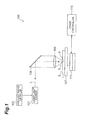
- a laser processing device 100 comprises a laser light source 101 which causes a laser light L to oscillate in a pulsating manner, a dichroic mirror 103 arranged such as to change the direction of the optical axis (optical path) of the laser light L by 90°, and a condenser lens 105 for converging the laser light L.
- the laser processing device 100 also comprises a support table 107 for supporting an object to be processed 1 irradiated with the laser light L converged by the condenser lens 105, a stage 111 for moving the support table 107, a laser light source controller 102 for controlling the laser light source 101 in order to regulate the output, pulse width, and the like of the laser light L, and a stage controller 115 for controlling the movement of the stage 111.
- the laser light L emitted from the laser light source 101 changes the direction of its optical axis by 90° with the dichroic mirror 103 and then is converged by the condenser lens 105 into the sheet-like object to be processed 1 mounted on the support table 107.
- the stage 111 is shifted, so that the object 1 moves relative to the laser light L along a part to form a modified region 5. This forms a modified region in the object 1 along the part 5.
- the part 5 is set in the object 1, for which a semiconductor material, a piezoelectric material, or the like is used.
- the part 5 is a virtual line extending straight.
- the laser light L is relatively moved along the part 5 (i.e., in the direction of arrow A in Fig. 2 ) while locating a converging point P within the object 1 as illustrated in Fig. 3 .
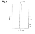
- This forms a modified region 7 within the object 1 along the part 5 as illustrated in Figs. 4 to 6 , whereby the modified region 7 becomes a removing region 8 to be removed by etching which will be explained later.
- the converging point P is a position at which the laser light L is converged.
- the part 5 may be curved instead of being straight, shaped into a three-dimensional form combining them, or specified in terms of coordinates.
- the modified region 7 may be formed either continuously or intermittently.
- the modified region 7 may be formed like lines or dots. It will be sufficient if the modified region 7 is formed at least within the object 1. There are cases where fractures are formed from the modified region 7 acting as a start point, and the fractures and modified region 7 may be exposed at outer surfaces (the front face, rear face, and outer peripheral face) of the object 1.
- the laser light L is absorbed in particular in the vicinity of the converging point P within the object 1 while being transmitted therethrough, whereby the modified region 7 is formed in the object 1 (i.e., internal absorption type laser processing).
- the processing region gradually progresses from the front face 3 side to the rear face side (i.e., surface absorption type laser processing) in general.
- the modified region 7 in accordance with this embodiment means regions whose physical characteristics such as density, refractive index, and mechanical strength have attained states different from those of their surroundings.
- Examples of the modified region 7 include molten processed regions, crack regions, dielectric breakdown regions, refractive index changed regions, and their mixed regions.
- Further examples of the modified region 7 include an area whose density region has changed from that of an unmodified region in a material of the object 1 and an area formed with a lattice defect (which may collectively be referred to as a high-density transitional region).
- the molten processed regions, refractive index changed regions, areas where the modified region has a density different from that of the unmodified region, or areas formed with a lattice defect may further incorporate a fracture (cut or microcrack) therewithin or at an interface between the modified region 7 and an unmodified region.
- the incorporated fracture may be formed over the whole surface of the modified region or in only a part or a plurality of parts thereof. Examples of the object 1 include those containing or constituted by glass (as will be explained later in detail).
- etching for example, a capillary action or the like is utilized so that fractures included in or extending from the modified region 7 are impregnated with an etchant, so as to advance the etching along fracture surfaces. This advances the etching selectively at a higher etching rate along the fractures in the object 1 and removes them. At the same time, by utilizing the characteristic feature that the etching rate of the modified region 7 itself is high, the etching is selectively advanced along the modified region 7, so as to remove the latter.
- Examples of the etching of this embodiment include a case where the object is immersed in the etchant (dipping) and a case where the object is coated with the etchant while being rotated (spin etching).
- the etching is isotropic etching.
- the etchant is used at a temperature ranging from ambient temperature to about 100°C, which is set appropriately according to a required etching rate or the like.
- a fluorine-based etchant examples of which include alkali solutions such as KOH (potassium hydroxide) which is an alkali etchant, HF (hydrofluoric acid), a mixed liquid of HF and H 2 O (water), and NH 4 F (saturated aqueous solution of ammonium bifluoride).
- alkali solutions such as KOH (potassium hydroxide) which is an alkali etchant, HF (hydrofluoric acid), a mixed liquid of HF and H 2 O (water), and NH 4 F (saturated aqueous solution of ammonium bifluoride).
- KOH potassium hydroxide
- HF hydrofluoric acid
- a mixed liquid of HF and H 2 O water
- NH 4 F saturated aqueous solution of ammonium bi
- the isotropic etching is applicable to relatively thin object to be processed (having a thickness of 10 ⁇ m to 100 ⁇ m, for example), so that the etching can advance isotropically independent of the crystal orientation and the modified region.
- the etchant travels through the fracture to wet the inside, so that the whole surface in the thickness direction becomes a start point for the modified region, whereby a chip etched such that its cut surface is depressed into a semicircular form can be taken out.
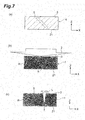
- Figs. 7 and 8 are flow diagrams illustrating the laser processing method in accordance with the first embodiment of the present invention.
- the following explanations will assume the thickness direction of the object 1 (the irradiation direction of the laser light L) to be the Z direction and one direction orthogonal to the thickness direction to be the X direction.
- this embodiment is a processing method for making a component (interposer or the like) for electrically connecting a semiconductor device and a printed wiring board or flexible substrate to each other, for example, and forms a through hole 24 (see Fig. 11 ) in the object 1 and inserts a conductor in the through hole 24, so as to produce a through-hole electrode.
- a component interposer or the like
- the object 1 is a glass substrate which can be discolored by browning and has a transparent color (transparency to visible light).
- a glass material other than silica glass (quartz) which has a high purity of SiO 2 . That is, the object 1 can be discolored by browning and is made of a glass material containing a predetermined amount or more of impurities which are compositions other than SiO 2 .
- the object 1 has front and rear faces 3, 21.
- a part to form a modified region 5 is programmably set along the part corresponding the through-hole 24 as being specified by three-dimensional coordinates.
- This part 5 is set such as to extend in a direction tilted with respect to the thickness direction of the object 1.
- the object 1 is irradiated with an X-ray 2 from the front face 3 side for a predetermined time as illustrated in Fig. 7(b) .
- This discolors the object 1 from the transparent color to dark yellowish brown by browning.
- a discolored part H exhibiting a low transmittance for the laser light L is formed throughout the object 1.
- the browning means a phenomenon in which glass is denatured upon irradiation with a fast neutron so as to be discolored (tinted).
- this embodiment discolors the object 1 such as to provide it with a shade corresponding to the size of a modified region 7 to be formed in a later stage.
- irradiation conditions such as the irradiation intensity of the X-ray and time are set so that the discolored part H is discolored by such a shade that the transmittance for the laser light L becomes a predetermined value.
- irradiation with the X-ray 2 is performed for a predetermined time under the irradiation conditions of 130 kV and 130 ⁇ A, so that the discolored part H exhibits a transmittance of several ten % (e.g., 20%) for the laser light L having a wavelength of 1064 nm.
- the object 1 is mounted and held on a mount table such that the front face 3 faces up, and the converging point of the laser light (hereinafter simply referred to as "converging point") is located on the rear face 21 side of the object 1. Then, while relatively moving the converging point in the X direction, the object 1 is irradiated (scanned) with the laser light L in an on/off mode from the front face 3 side. This forms a modified region 7 having a size corresponding to the shade of the discolored part H along the part 5 on the rear face 21 side of the discolored part H.
- the laser light L has an output of 0.6 W/pulse and a pulse width of 100 ns.
- the laser light L has a wavelength of 1064 nm, for example, and a pulse pitch of 0.25 ⁇ m (400 kHz_100 mm/s). Since a pulsed laser light is used as the laser light L for spot irradiation, the resulting modified region 7 is constituted by a modified spot.
- the modified region 7 incorporates therein fractures generated therefrom (as in modified regions which will follow).
- the above-mentioned scan is repeatedly performed while progressively changing the Z-direction position of the converging point from the rear face 21 side to the front face 3 side in the object 1.
- This forms modified regions 7 joining each other along the part corresponding to the through hole 24 in the object 1. That is, the modified region 7 of the object 1 is formed in the discolored part H within the object 1.
- the object 1 is etched. Specifically, the object 1 is infiltrated with an etchant from the front face 3 side and rear face 21 side to the modified region 7, such as to advance the etching selectively along the modified region 7 and fractures incorporated therein. This selectively removes the inside of the object 1 along the modified region 7, thereby forming the through hole 24 in the object 1.
- an etchant from the front face 3 side and rear face 21 side to the modified region 7, such as to advance the etching selectively along the modified region 7 and fractures incorporated therein. This selectively removes the inside of the object 1 along the modified region 7, thereby forming the through hole 24 in the object 1.
- the object 1 is heat-treated at about 400°C, so as to cause the discolored part H to regain its color. That is, the transparency of the object 1 is restored (resumed), so that the color of the object 1 is returned to the original transparent color before discoloring. Thereafter, the object 1 is oxidized by wet oxidation or the like, so as to produce an electrically insulating film on the inner face of the through hole 24, and a conductor is inserted into the through hole 24. Then, electrode pads are formed on the front face 3 and rear face 21 so as to connect electrically with the conductor, whereby a through-hole electrode is constructed.
- this embodiment discolors the object 1 by browning, so as to lower the transmittance for the laser light L in the discolored part H, whereby absorption of the laser light L is induced in the discolored part H, so that the modified region 7 is easily formed by convergence of the laser light L. Therefore, this embodiment can enhance the processability as easiness to process for the laser light L in the object 1 made of glass, thereby reducing the necessity for the laser light to attain a very short pulse or short wavelength.
- the productivity can be improved.
- this embodiment causes the discolored part H to regain its color by heat treatment and thus can inhibit the discoloring by browning from adversely affecting products.
- this embodiment discolors the object 1 such as to provide it with a shade corresponding to the size of the modified region 7 to be formed. That is, the intensity and time of irradiation with the X-ray 2 is controlled so as to adjust the shade of the discolored part H, whereby the absorptance of the laser light L in the object 1 is regulated.
- the processing size (the size of the modified region 7) can favorably be controlled by utilizing the difference in absorptance of the laser light L.
- darkening the discolored part H can form a larger modified region 7 by convergence of the laser light L, while brightening the discolored part H can form a smaller modified region 7 by convergence of the laser light L.
- This embodiment also yields the following operations and effects.
- the modified region 7 and fractures incorporated therein can be removed from the processed object 1 by etching, whereby its strength and quality can be improved. Since no cutting dust occurs during processing, an environment-friendly processing method can be achieved.
- interposers and the like made by this embodiment can attain very thin wiring pitches, easy designing of wirings, and lower electric resistance in wirings.
- This embodiment irradiates the object 1 with the X-ray 2 as mentioned above and thus may be hard to apply to a laser processing method for cutting the object 1 into semiconductor chips and the like.
- this embodiment is used for forming the through hole 24 in the object 1 and can be considered less likely to have such a problem.
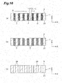
- Figs. 9 and 10 are flow diagrams illustrating the laser processing method in accordance with the second embodiment of the present invention. This embodiment will be explained mainly in terms of differences from the above-mentioned first embodiment.
- the laser processing method in accordance with this embodiment forms a mask 12 having a predetermined pattern on the front face 3 of the object 1.
- the mask 12 is constituted by a material (e.g., lead) which does not transmit the X-ray 2 therethrough and has a plurality of openings 12a arranged in a row along the X direction.
- the object 1 is surface-irradiated with the X-ray 2 for a predetermined time from the front face 3 side.
- This discolors the object 1 selectively according to the predetermined pattern of the mask 12.
- the X-ray 2 enters only the regions corresponding to the openings 12a of the mask 12 in the object 1, whereby a plurality of discolored parts H are arranged in a row along the X direction.
- the mask 12 is removed as illustrated in Fig. 9(c) , and then, as illustrated in Fig. 10(a) , the object 1 is continuously irradiated with the laser light L under a fixed laser condition while locating the converging point on the rear face 21 side and relatively moving (scanning) the laser light L in the X direction. That is, the laser light L is relatively moved in the X direction so as to traverse the plurality of discolored parts H while irradiating them. As a consequence, modified regions 7 are formed in the respective discolored parts H because of their low transparency, while no modified regions are formed in the undiscolored parts because of their high transparency even when the laser light L is converged.
- the above-mentioned scan is repeatedly performed while progressively changing the Z-direction position of the converging point from the rear face 21 side to the front face 3 side in the object 1.
- This forms modified regions 7 joining each other in the discolored parts H within the object 1 as illustrated in Fig. 10(b) .
- the object 1 is etched, so as to remove the inside of the object 1 selectively along the modified regions 7. This removes a plurality of discolored parts H, thereby forming a plurality of through holes 24 extending in the Z direction.
- this embodiment also achieves the above-mentioned operation and effect of enhancing the processability for the laser light L in the object 1 made of glass.
- this embodiment regulates regions with or without browning in the object 1 by using the mask 12, so as to discolor a plurality of parts of the object 1.
- it partly browns the object 1 through the mask 12, so as to produce regions transparent and nontransparent to the laser light L in the same object 1.
- the laser light L irradiates the object 1 while relatively moving so as to transverse a plurality of discolored parts H, thereby selectively modifying the discolored parts H. Therefore, a plurality of modified regions 7 can be formed accurately in the object 1 without being irradiated with the laser light L in an on/off mode.
- irradiation condition control of the laser light L which is highly accurate and critical becomes unnecessary for forming a plurality of modified regions 7 in the object 1.
- Figs. 11 and 12 are flow diagrams illustrating the laser processing method in accordance with the third embodiment of the present invention. This embodiment will be explained mainly in terms of differences from the above-mentioned first embodiment.
- the laser processing method of this embodiment forms a mask 12 having a predetermined pattern on the front face 3 of the object 1.
- the mask 12 masks both end parts of the object 1 and is formed with an opening 12a which widely opens from its one end side to the other end side.
- the object 1 is spot-irradiated (irradiated while being provided with an intensity distribution by utilizing diffraction) with the X-ray 2.
- the X-ray 2 has an intensity distribution 2a shaped like a quadratic curve which is higher on the center side and quadratically decreases therefrom to the outer sides.
- the object 1 is repeatedly scanned with the laser light L in an on/off mode under a fixed irradiation condition while relatively moving the converging point in the X direction and progressively changing the Z-direction position of the converging point from the rear face 21 side to the front face 3 side in the object 1.
- modified regions 7 having sizes corresponding to shades of the discolored part H1 are formed such as to join with each other along the parts corresponding to through holes 24 in the discolored part H1.
- the discolored part H has a gradation according to which the transmittance of the laser light varies as mentioned above, a plurality of modified regions 7 having sizes varying according to the gradation can be formed collectively by the above-mentioned scan. Specifically, the sizes of the plurality of modified regions 7 formed collectively become greater on the center side of the object 1 and smaller on the outer sides.
- the object 1 is etched, so as to remove the inside of the object 1 selectively along the modified regions 7.
- This collectively forms a plurality of through holes 24 having diameters different from each other in conformity to the sizes of the modified regions 7.
- the diameters of the through holes 24 correspond to the sizes of the modified regions 7, i.e., the gradation of the discolored part H1, so that the diameter of the through holes 24 is greater on the center side of the object 1 and becomes smaller on the outer sides.
- this embodiment also achieves the above-mentioned operation and effect of enhancing the processability for the laser light L in the object 1 made of glass.
- this embodiment can collectively form a plurality of modified regions 7 having different sizes according to the gradation under a fixed irradiation condition of the laser light L. That is, appropriately irradiating the object 1 in an on/off mode under a fixed laser condition while relatively moving the converging point can form greater and smaller modified regions 7 in darker and brighter regions in the discolored part H1.
- the discolored part H1 has a gradation which is darker on the center side and becomes brighter on the outer sides, the gradation of the discolored part is not limited thereto.
- Fig. 13 it may have a gradation which becomes brighter (or darker) from one end side to the other end side in the X direction of the object 1.
- an X-ray absorption filter 13 is disposed on the front face 3 of the object 1 as illustrated in Fig. 13(a) .
- the X-ray absorption filter 13 has a pattern corresponding to the gradation of the discolored part H, which gradually becomes greater (or smaller) from one end side to the other end side in the X direction of the object 1 here.
- the object 1 is surface-irradiated with the X-ray 2 through the X-ray absorption filter 13.
- the X-ray 2 incident on the object 1 attains an intensity distribution 2b in which the intensity gradually becomes smaller (greater) from one end side to the other end side in the X direction of the object 1.
- the object 1 is irradiated with the laser light L appropriately in an on/off mode under a fixed condition while relatively moving the converging point, whereby a plurality of modified regions 7 are formed in the discolored part H2 such as to reduce their sizes from one end side to the other end side in the X direction.
- a plurality of discolored parts H3 may be formed at given positions in the object 1, while having a gradation among them.
- an X-ray absorption mechanism 14 equipped with a plurality of switchable X-ray absorption filters having different transmittances is used such that a plurality of given positions are irradiated with the X-ray 2 so as to yield intensity distributions different from each other.
- the X-ray absorption filters of the X-ray absorption mechanism 14 are switched such that the intensity distribution 2c of the incident X-ray becomes greater than that upon irradiation with the X-ray 2 at a position on the other end side.
- a plurality of discolored parts H3 which become brighter from one end side to the other end side in the X direction of the object 1 are formed in the object 1 as illustrated in Fig. 14(b) .
- the laser light entrance surface for forming the modified regions is not limited to the front face 3 of the object 1, but may be the rear face 21 of the object 1.
- the above-mentioned embodiments emit the X-ray 2 for browning
- radiations other than the X-ray 2 may be emitted as long as the object can be discolored by browning.
- all the discolored parts H regain the color in the above-mentioned embodiments, at least a part of the modified regions may regain the color.
- the above-mentioned embodiments form a plurality of modified regions 7 by repeatedly performing a scan which moves the converging point along the front face 3 of the object 1 while changing the converging point position in the Z direction, in which the direction and order of scanning is not limited.
- irradiation with the laser light L while moving the converging point along a through hole 24 to form a modified region 7 may be repeated by the number of through holes 24.
- the on/off irradiation with the laser light L in the above-mentioned embodiments may be performed not only by controlling the on/off of the emission of the laser light L, but also by opening/closing a shutter disposed on the optical path of the laser light L or by masking on/off the front face 3 of the object 1, for example.
- the intensity of the laser light L may be controlled between an intensity at a threshold for forming the modified region 7 (processing threshold) or higher and an intensity lower than the processing threshold.
- the laser processing method in accordance with the present invention can enhance the processability for the laser light in the object made of glass.
Landscapes
- Engineering & Computer Science (AREA)
- Chemical & Material Sciences (AREA)
- Optics & Photonics (AREA)
- Physics & Mathematics (AREA)
- Plasma & Fusion (AREA)
- Mechanical Engineering (AREA)
- General Chemical & Material Sciences (AREA)
- Chemical Kinetics & Catalysis (AREA)
- Geochemistry & Mineralogy (AREA)
- Materials Engineering (AREA)
- Organic Chemistry (AREA)
- Life Sciences & Earth Sciences (AREA)
- Toxicology (AREA)
- Health & Medical Sciences (AREA)
- Oil, Petroleum & Natural Gas (AREA)
- Laser Beam Processing (AREA)
- Surface Treatment Of Glass (AREA)
- Re-Forming, After-Treatment, Cutting And Transporting Of Glass Products (AREA)
Abstract
Description
- The present invention relates to a laser processing method and, in particular, to a laser processing method for forming a through hole in an object to be processed.
- Known as a conventional laser processing method is one comprising converging a laser light into an object to be processed made of glass so as to form a modified region and etching the object so as to remove the modified region, thereby forming a through hole in the object (see, for example, Patent Literature 1).
- Patent Literature 1: Japanese Patent Application Laid-Open No.
2005-206401 - In laser processing methods such as the one mentioned above, the transmittance of glass for the laser light is so high that the laser light is required to have a very short pulse or a short wavelength, for example, in order to converge the laser light at the object made of glass and form the modified region, whereby the modified region may be hard to form. Hence, it has been desired for the laser processing methods such as the one mentioned above to enhance the processability for the laser light in the object made of glass.
- It is therefore an object of the present invention to provide a laser processing method which can enhance the processability for a laser light in an object to be processed made of glass.
- One aspect of the present invention relates to a laser processing method. This laser processing method is a laser processing method of converging a laser light into an object to be processed made of glass so as to form a modified region and etching the object along the modified region so as to form a through hole in the object, the method comprising a browning step of discoloring at least a part of the object by browning; a laser light converging step of forming the modified region in a discolored part of the object by converging the laser light into the object after the browning step; and an etching step of etching the object after the laser light converging step so as to advance the etching selectively along the modified region and form the through hole.
- This laser processing method can lower the transmittance for the laser light in the discolored part of the object discolored by browning, so as to induce absorption of the laser light. This makes it easier to form the modified region by convergence of the laser light in the discolored part of the object. Hence, the processability for the laser light can be enhanced in the object made of glass.
- The method may further comprise a color recovery step of recovering a color in at least a part of the discolored part in the object by heat-treating the object after the laser light converging step. This enables the discolored part in the object to regain its color before discoloring.
- The browning step may discolor a plurality of parts in the object, while the laser light converging step may irradiate the object with the laser light while relatively moving the laser light in one direction so as to traverse the plurality of discolored parts. In this case, when irradiated with the relatively moving laser light, each of the discolored parts is likely to absorb the laser light because of their low transmittance, whereby the modified region is formed easily. On the other hand, the parts not discolored exhibit high transmittance and thus are hard to form modified regions. Therefore, a plurality of modified regions can easily be formed in the object without performing laser light irradiation in an on/off mode, whereby laser light irradiation condition control which is highly accurate and critical becomes unnecessary for forming a plurality of modified regions in the object.
- The discolored part may have a shade corresponding to a size of the modified region to be formed in the laser light converging step. In this case, since the discolored part has a transmittance for the laser light corresponding to the shade, the size of the modified region formed by convergence of the laser light can be controlled by the shade of the discolored part of the object.
- The discolored part may have a gradation. In this case, for the laser light, the discolored part exhibits a transmittance changing stepwise according to the gradation. Therefore, a plurality of modified regions having different sizes can be formed collectively according to the gradation.
- The laser processing method of the present invention can enhance the processability for a laser light in an object to be processed made of glass.
-
- [
Fig. 1 ] is a schematic structural diagram of a laser processing device used for forming a modified region; - [
Fig. 2 ] is a plan view of an object to be processed in which the modified region is to be formed; - [
Fig. 3 ] is a sectional view of the object taken along the line III-III ofFig. 2 ; - [
Fig. 4 ] is a plan view of the object after laser processing; - [
Fig. 5 ] is a sectional view of the object taken along the line V-V ofFig. 4 ; - [
Fig. 6 ] is a sectional view of the object taken along the line VI-VI ofFig. 4 ; - [
Fig. 7 ] (a) is a flow diagram illustrating the laser processing method in accordance with a first embodiment of the present invention, (b) is a flow diagram illustrating a sequel toFig. 7(a), and (c) is a flow diagram illustrating a sequel toFig. 7(b) ; - [
Fig. 8 ] (a) is a flow diagram illustrating a sequel toFig. 7(c), (b) is a flow diagram illustrating a sequel toFig. 8(a), and (c) is a flow diagram illustrating a sequel toFig. 8(b) ; - [
Fig. 9 ] (a) is a flow diagram illustrating the laser processing method in accordance with a second embodiment of the present invention, (b) is a flow diagram illustrating a sequel toFig. 9(a), and (c) is a flow diagram illustrating a sequel toFig. 9(b) ; - [
Fig. 10 ] (a) is a flow diagram illustrating a sequel toFig. 9(c), (b) is a flow diagram illustrating a sequel toFig. 10(a), and (c) is a flow diagram illustrating a sequel toFig. 10(b) ; - [
Fig. 11 ] (a) is a flow diagram illustrating the laser processing method in accordance with a third embodiment of the present invention, while (b) is a flow diagram illustrating a sequel toFig. 11(a) ; - [
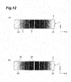
Fig. 12 ] (a) is a flow diagram illustrating a sequel to Fig. 11(c), while (b) is a flow diagram illustrating a sequel toFig. 12(a) ; - [
Fig. 13 ] (a) is a flow diagram illustrating the laser processing method in accordance with a modified example, (b) is a flow diagram illustrating a sequel toFig. 13(a), and (c) is a flow diagram illustrating a sequel toFig. 13(b) ; and - [
Fig. 14 ] (a) is a flow diagram illustrating the laser processing method in accordance with another modified example, (b) is a flow diagram illustrating a sequel toFig. 14(a), and (c) is a flow diagram illustrating a sequel toFig. 14(b) . - In the following, preferred embodiments of the present invention will be explained in detail with reference to the drawings. In the following explanations, the same or equivalent constituents will be referred to with the same signs while omitting their overlapping descriptions.
- The laser processing method in accordance with an embodiment converges a laser light into an object to be processed, so as to form a modified region. Therefore, the forming of the modified region will firstly be explained in the following with reference to
Figs. 1 to 6 . - As illustrated in
Fig. 1 , alaser processing device 100 comprises alaser light source 101 which causes a laser light L to oscillate in a pulsating manner, adichroic mirror 103 arranged such as to change the direction of the optical axis (optical path) of the laser light L by 90°, and acondenser lens 105 for converging the laser light L. Thelaser processing device 100 also comprises a support table 107 for supporting an object to be processed 1 irradiated with the laser light L converged by thecondenser lens 105, astage 111 for moving the support table 107, a laserlight source controller 102 for controlling thelaser light source 101 in order to regulate the output, pulse width, and the like of the laser light L, and astage controller 115 for controlling the movement of thestage 111. - In the
laser processing device 100, the laser light L emitted from thelaser light source 101 changes the direction of its optical axis by 90° with thedichroic mirror 103 and then is converged by thecondenser lens 105 into the sheet-like object to be processed 1 mounted on the support table 107. At the same time, thestage 111 is shifted, so that theobject 1 moves relative to the laser light L along a part to form a modifiedregion 5. This forms a modified region in theobject 1 along thepart 5. - As illustrated in
Fig. 2 , thepart 5 is set in theobject 1, for which a semiconductor material, a piezoelectric material, or the like is used. Here, thepart 5 is a virtual line extending straight. When forming a modified region within theobject 1, the laser light L is relatively moved along the part 5 (i.e., in the direction of arrow A inFig. 2 ) while locating a converging point P within theobject 1 as illustrated inFig. 3 . This forms a modifiedregion 7 within theobject 1 along thepart 5 as illustrated inFigs. 4 to 6 , whereby the modifiedregion 7 becomes a removingregion 8 to be removed by etching which will be explained later. - The converging point P is a position at which the laser light L is converged. The
part 5 may be curved instead of being straight, shaped into a three-dimensional form combining them, or specified in terms of coordinates. Themodified region 7 may be formed either continuously or intermittently. Themodified region 7 may be formed like lines or dots. It will be sufficient if the modifiedregion 7 is formed at least within theobject 1. There are cases where fractures are formed from the modifiedregion 7 acting as a start point, and the fractures and modifiedregion 7 may be exposed at outer surfaces (the front face, rear face, and outer peripheral face) of theobject 1. - Here, the laser light L is absorbed in particular in the vicinity of the converging point P within the
object 1 while being transmitted therethrough, whereby themodified region 7 is formed in the object 1 (i.e., internal absorption type laser processing). In the case of forming a removing part such as a hole or groove by melting it away from thefront face 3, the processing region gradually progresses from thefront face 3 side to the rear face side (i.e., surface absorption type laser processing) in general. - The modified
region 7 in accordance with this embodiment means regions whose physical characteristics such as density, refractive index, and mechanical strength have attained states different from those of their surroundings. Examples of the modifiedregion 7 include molten processed regions, crack regions, dielectric breakdown regions, refractive index changed regions, and their mixed regions. Further examples of the modifiedregion 7 include an area whose density region has changed from that of an unmodified region in a material of theobject 1 and an area formed with a lattice defect (which may collectively be referred to as a high-density transitional region). - The molten processed regions, refractive index changed regions, areas where the modified region has a density different from that of the unmodified region, or areas formed with a lattice defect may further incorporate a fracture (cut or microcrack) therewithin or at an interface between the modified
region 7 and an unmodified region. The incorporated fracture may be formed over the whole surface of the modified region or in only a part or a plurality of parts thereof. Examples of theobject 1 include those containing or constituted by glass (as will be explained later in detail). - Here, this embodiment forms the modified
region 7 in theobject 1 and then etches theobject 1, so as to advance the etching selectively along fractures (also known as cracks, microcracks, cuts, and the like; hereinafter simply referred to as "fractures") included in or extending from the modifiedregion 7, thereby removing a part extending along the modifiedregion 7 in theobject 1. - In the etching in this embodiment, for example, a capillary action or the like is utilized so that fractures included in or extending from the modified
region 7 are impregnated with an etchant, so as to advance the etching along fracture surfaces. This advances the etching selectively at a higher etching rate along the fractures in theobject 1 and removes them. At the same time, by utilizing the characteristic feature that the etching rate of the modifiedregion 7 itself is high, the etching is selectively advanced along the modifiedregion 7, so as to remove the latter. - Examples of the etching of this embodiment include a case where the object is immersed in the etchant (dipping) and a case where the object is coated with the etchant while being rotated (spin etching). Here, the etching is isotropic etching.
- The etchant is used at a temperature ranging from ambient temperature to about 100°C, which is set appropriately according to a required etching rate or the like. Employed as the etchant is a fluorine-based etchant, examples of which include alkali solutions such as KOH (potassium hydroxide) which is an alkali etchant, HF (hydrofluoric acid), a mixed liquid of HF and H2O (water), and NH4F (saturated aqueous solution of ammonium bifluoride). Employable as the etchant are not only liquids but also those in the form of a gel (jelly or semisolid).
- The isotropic etching is applicable to relatively thin object to be processed (having a thickness of 10 µm to 100 µm, for example), so that the etching can advance isotropically independent of the crystal orientation and the modified region. When a fracture is exposed to a front face in this case, the etchant travels through the fracture to wet the inside, so that the whole surface in the thickness direction becomes a start point for the modified region, whereby a chip etched such that its cut surface is depressed into a semicircular form can be taken out.
- The laser processing method in accordance with the first embodiment of the present invention will now be explained in detail.
Figs. 7 and8 are flow diagrams illustrating the laser processing method in accordance with the first embodiment of the present invention. The following explanations will assume the thickness direction of the object 1 (the irradiation direction of the laser light L) to be the Z direction and one direction orthogonal to the thickness direction to be the X direction. - As illustrated in
Figs. 7 and8 , this embodiment is a processing method for making a component (interposer or the like) for electrically connecting a semiconductor device and a printed wiring board or flexible substrate to each other, for example, and forms a through hole 24 (seeFig. 11 ) in theobject 1 and inserts a conductor in the throughhole 24, so as to produce a through-hole electrode. - As illustrated in
Fig. 7(a) , theobject 1 is a glass substrate which can be discolored by browning and has a transparent color (transparency to visible light). Employed as theobject 1 is a glass material other than silica glass (quartz) which has a high purity of SiO2. That is, theobject 1 can be discolored by browning and is made of a glass material containing a predetermined amount or more of impurities which are compositions other than SiO2. Theobject 1 has front andrear faces - In the
object 1, a part to form a modifiedregion 5 is programmably set along the part corresponding the through-hole 24 as being specified by three-dimensional coordinates. Thispart 5 is set such as to extend in a direction tilted with respect to the thickness direction of theobject 1. - First, when processing the
object 1 by the laser processing method of this embodiment, theobject 1 is irradiated with anX-ray 2 from thefront face 3 side for a predetermined time as illustrated inFig. 7(b) . This discolors theobject 1 from the transparent color to dark yellowish brown by browning. As a result, a discolored part H exhibiting a low transmittance for the laser light L is formed throughout theobject 1. The browning means a phenomenon in which glass is denatured upon irradiation with a fast neutron so as to be discolored (tinted). - During the tinting by browning, this embodiment discolors the
object 1 such as to provide it with a shade corresponding to the size of a modifiedregion 7 to be formed in a later stage. Specifically, irradiation conditions such as the irradiation intensity of the X-ray and time are set so that the discolored part H is discolored by such a shade that the transmittance for the laser light L becomes a predetermined value. For example, irradiation with theX-ray 2 is performed for a predetermined time under the irradiation conditions of 130 kV and 130 µA, so that the discolored part H exhibits a transmittance of several ten % (e.g., 20%) for the laser light L having a wavelength of 1064 nm. - Subsequently, as illustrated in
Fig. 7(c) , theobject 1 is mounted and held on a mount table such that thefront face 3 faces up, and the converging point of the laser light (hereinafter simply referred to as "converging point") is located on therear face 21 side of theobject 1. Then, while relatively moving the converging point in the X direction, theobject 1 is irradiated (scanned) with the laser light L in an on/off mode from thefront face 3 side. This forms a modifiedregion 7 having a size corresponding to the shade of the discolored part H along thepart 5 on therear face 21 side of the discolored part H. - Here, the laser light L has an output of 0.6 W/pulse and a pulse width of 100 ns. The laser light L has a wavelength of 1064 nm, for example, and a pulse pitch of 0.25 µm (400 kHz_100 mm/s). Since a pulsed laser light is used as the laser light L for spot irradiation, the resulting modified
region 7 is constituted by a modified spot. The modifiedregion 7 incorporates therein fractures generated therefrom (as in modified regions which will follow). - Next, as illustrated in
Fig. 8(a) , the above-mentioned scan is repeatedly performed while progressively changing the Z-direction position of the converging point from therear face 21 side to thefront face 3 side in theobject 1. This forms modifiedregions 7 joining each other along the part corresponding to the throughhole 24 in theobject 1. That is, the modifiedregion 7 of theobject 1 is formed in the discolored part H within theobject 1. - Subsequently, as illustrated in
Fig. 8(b) , theobject 1 is etched. Specifically, theobject 1 is infiltrated with an etchant from thefront face 3 side andrear face 21 side to the modifiedregion 7, such as to advance the etching selectively along the modifiedregion 7 and fractures incorporated therein. This selectively removes the inside of theobject 1 along the modifiedregion 7, thereby forming the throughhole 24 in theobject 1. - Next, as illustrated in
Fig. 8(c) , theobject 1 is heat-treated at about 400°C, so as to cause the discolored part H to regain its color. That is, the transparency of theobject 1 is restored (resumed), so that the color of theobject 1 is returned to the original transparent color before discoloring. Thereafter, theobject 1 is oxidized by wet oxidation or the like, so as to produce an electrically insulating film on the inner face of the throughhole 24, and a conductor is inserted into the throughhole 24. Then, electrode pads are formed on thefront face 3 andrear face 21 so as to connect electrically with the conductor, whereby a through-hole electrode is constructed. - As in the foregoing, this embodiment discolors the
object 1 by browning, so as to lower the transmittance for the laser light L in the discolored part H, whereby absorption of the laser light L is induced in the discolored part H, so that the modifiedregion 7 is easily formed by convergence of the laser light L. Therefore, this embodiment can enhance the processability as easiness to process for the laser light L in theobject 1 made of glass, thereby reducing the necessity for the laser light to attain a very short pulse or short wavelength. - As a result, it becomes unnecessary to modify irradiation conditions such as wavelength in the laser light L each time the material for the
object 1 is changed. Hence, not only theobject 1 made of glass, but also theobject 1 made of other materials such as silicon can be laser-processed by using the same laser light source, whereby the productivity can be improved. - As mentioned above, this embodiment causes the discolored part H to regain its color by heat treatment and thus can inhibit the discoloring by browning from adversely affecting products.
- As mentioned above, this embodiment discolors the
object 1 such as to provide it with a shade corresponding to the size of the modifiedregion 7 to be formed. That is, the intensity and time of irradiation with theX-ray 2 is controlled so as to adjust the shade of the discolored part H, whereby the absorptance of the laser light L in theobject 1 is regulated. Hence, under the same irradiation condition of the laser light L, the processing size (the size of the modified region 7) can favorably be controlled by utilizing the difference in absorptance of the laser light L. As a result, darkening the discolored part H can form a larger modifiedregion 7 by convergence of the laser light L, while brightening the discolored part H can form a smaller modifiedregion 7 by convergence of the laser light L. - This embodiment also yields the following operations and effects. For example, when forming the through
hole 24, the modifiedregion 7 and fractures incorporated therein can be removed from the processedobject 1 by etching, whereby its strength and quality can be improved. Since no cutting dust occurs during processing, an environment-friendly processing method can be achieved. For example, interposers and the like made by this embodiment can attain very thin wiring pitches, easy designing of wirings, and lower electric resistance in wirings. - This embodiment irradiates the
object 1 with theX-ray 2 as mentioned above and thus may be hard to apply to a laser processing method for cutting theobject 1 into semiconductor chips and the like. In this regard, this embodiment is used for forming the throughhole 24 in theobject 1 and can be considered less likely to have such a problem. - The second embodiment of the present invention will now be explained.
Figs. 9 and10 are flow diagrams illustrating the laser processing method in accordance with the second embodiment of the present invention. This embodiment will be explained mainly in terms of differences from the above-mentioned first embodiment. - First, as illustrated in
Fig. 9(a) , the laser processing method in accordance with this embodiment forms amask 12 having a predetermined pattern on thefront face 3 of theobject 1. Here, themask 12 is constituted by a material (e.g., lead) which does not transmit theX-ray 2 therethrough and has a plurality ofopenings 12a arranged in a row along the X direction. - Subsequently, as illustrated in
Fig. 9(b) , theobject 1 is surface-irradiated with theX-ray 2 for a predetermined time from thefront face 3 side. This discolors theobject 1 selectively according to the predetermined pattern of themask 12. Specifically, theX-ray 2 enters only the regions corresponding to theopenings 12a of themask 12 in theobject 1, whereby a plurality of discolored parts H are arranged in a row along the X direction. - Next, the
mask 12 is removed as illustrated inFig. 9(c) , and then, as illustrated inFig. 10(a) , theobject 1 is continuously irradiated with the laser light L under a fixed laser condition while locating the converging point on therear face 21 side and relatively moving (scanning) the laser light L in the X direction. That is, the laser light L is relatively moved in the X direction so as to traverse the plurality of discolored parts H while irradiating them. As a consequence, modifiedregions 7 are formed in the respective discolored parts H because of their low transparency, while no modified regions are formed in the undiscolored parts because of their high transparency even when the laser light L is converged. - Subsequently, the above-mentioned scan is repeatedly performed while progressively changing the Z-direction position of the converging point from the
rear face 21 side to thefront face 3 side in theobject 1. This forms modifiedregions 7 joining each other in the discolored parts H within theobject 1 as illustrated inFig. 10(b) . Then, as illustrated inFig. 10(c) , theobject 1 is etched, so as to remove the inside of theobject 1 selectively along the modifiedregions 7. This removes a plurality of discolored parts H, thereby forming a plurality of throughholes 24 extending in the Z direction. - As in the foregoing, this embodiment also achieves the above-mentioned operation and effect of enhancing the processability for the laser light L in the
object 1 made of glass. - As mentioned above, this embodiment regulates regions with or without browning in the
object 1 by using themask 12, so as to discolor a plurality of parts of theobject 1. In other words, it partly browns theobject 1 through themask 12, so as to produce regions transparent and nontransparent to the laser light L in thesame object 1. Then, under a fixed irradiation condition, the laser light L irradiates theobject 1 while relatively moving so as to transverse a plurality of discolored parts H, thereby selectively modifying the discolored parts H. Therefore, a plurality of modifiedregions 7 can be formed accurately in theobject 1 without being irradiated with the laser light L in an on/off mode. Hence, irradiation condition control of the laser light L which is highly accurate and critical becomes unnecessary for forming a plurality of modifiedregions 7 in theobject 1. - The third embodiment of the present invention will now be explained.
Figs. 11 and12 are flow diagrams illustrating the laser processing method in accordance with the third embodiment of the present invention. This embodiment will be explained mainly in terms of differences from the above-mentioned first embodiment. - First, as illustrated in
Fig. 11(a) , the laser processing method of this embodiment forms amask 12 having a predetermined pattern on thefront face 3 of theobject 1. Here, themask 12 masks both end parts of theobject 1 and is formed with anopening 12a which widely opens from its one end side to the other end side. - Subsequently, the
object 1 is spot-irradiated (irradiated while being provided with an intensity distribution by utilizing diffraction) with theX-ray 2. Here, theX-ray 2 has anintensity distribution 2a shaped like a quadratic curve which is higher on the center side and quadratically decreases therefrom to the outer sides. This forms theobject 1 with a discolored part H1 which is discolored such as to have a gradation as a stepwise shade which is darker on the center side and gradually becomes brighter on the outer sides as illustrated inFig. 11(b) . - Next, as illustrated in
Fig. 12(a) , theobject 1 is repeatedly scanned with the laser light L in an on/off mode under a fixed irradiation condition while relatively moving the converging point in the X direction and progressively changing the Z-direction position of the converging point from therear face 21 side to thefront face 3 side in theobject 1. As a consequence, modifiedregions 7 having sizes corresponding to shades of the discolored part H1 are formed such as to join with each other along the parts corresponding to throughholes 24 in the discolored part H1. - Here, since the discolored part H has a gradation according to which the transmittance of the laser light varies as mentioned above, a plurality of modified
regions 7 having sizes varying according to the gradation can be formed collectively by the above-mentioned scan. Specifically, the sizes of the plurality of modifiedregions 7 formed collectively become greater on the center side of theobject 1 and smaller on the outer sides. - Subsequently, as illustrated in
Fig. 12(b) , theobject 1 is etched, so as to remove the inside of theobject 1 selectively along the modifiedregions 7. This collectively forms a plurality of throughholes 24 having diameters different from each other in conformity to the sizes of the modifiedregions 7. Here, the diameters of the throughholes 24 correspond to the sizes of the modifiedregions 7, i.e., the gradation of the discolored part H1, so that the diameter of the throughholes 24 is greater on the center side of theobject 1 and becomes smaller on the outer sides. - As in the foregoing, this embodiment also achieves the above-mentioned operation and effect of enhancing the processability for the laser light L in the
object 1 made of glass. - As mentioned above, since the discolored part H1 has a gradation, this embodiment can collectively form a plurality of modified
regions 7 having different sizes according to the gradation under a fixed irradiation condition of the laser light L. That is, appropriately irradiating theobject 1 in an on/off mode under a fixed laser condition while relatively moving the converging point can form greater and smaller modifiedregions 7 in darker and brighter regions in the discolored part H1. - While the discolored part H1 has a gradation which is darker on the center side and becomes brighter on the outer sides, the gradation of the discolored part is not limited thereto.
- For example, as illustrated in
Fig. 13 , it may have a gradation which becomes brighter (or darker) from one end side to the other end side in the X direction of theobject 1. First, in this case, anX-ray absorption filter 13 is disposed on thefront face 3 of theobject 1 as illustrated inFig. 13(a) . TheX-ray absorption filter 13 has a pattern corresponding to the gradation of the discolored part H, which gradually becomes greater (or smaller) from one end side to the other end side in the X direction of theobject 1 here. - Subsequently, the
object 1 is surface-irradiated with theX-ray 2 through theX-ray absorption filter 13. As a consequence, theX-ray 2 incident on theobject 1 attains anintensity distribution 2b in which the intensity gradually becomes smaller (greater) from one end side to the other end side in the X direction of theobject 1. This forms a discolored part H2 in theobject 1 as illustrated inFig. 13(b) . - Thereafter, as illustrated in
Fig. 13(c) , theobject 1 is irradiated with the laser light L appropriately in an on/off mode under a fixed condition while relatively moving the converging point, whereby a plurality of modifiedregions 7 are formed in the discolored part H2 such as to reduce their sizes from one end side to the other end side in the X direction. - As illustrated in
Fig. 14 , for example, a plurality of discolored parts H3 may be formed at given positions in theobject 1, while having a gradation among them. In this case, as illustrated inFig. 14(a) , anX-ray absorption mechanism 14 equipped with a plurality of switchable X-ray absorption filters having different transmittances is used such that a plurality of given positions are irradiated with theX-ray 2 so as to yield intensity distributions different from each other. - Here, when irradiating the
object 1 with theX-ray 2 at a position on one end side in the X direction of theobject 1, the X-ray absorption filters of theX-ray absorption mechanism 14 are switched such that theintensity distribution 2c of the incident X-ray becomes greater than that upon irradiation with theX-ray 2 at a position on the other end side. As a result, a plurality of discolored parts H3 which become brighter from one end side to the other end side in the X direction of theobject 1 are formed in theobject 1 as illustrated inFig. 14(b) . - Thereafter, as illustrated in
Fig. 14(c) , scanning with the laser light appropriately in an on/off mode under a fixed laser condition while relatively moving the converging point forms a plurality of modifiedregions 7 in the respective discolored parts H3 such that their sizes become smaller from one end side to the other end side in the X direction. - Though preferred embodiments of the present invention have been explained in the foregoing, the present invention is not limited thereto but may be modified or applied to others within the scope not changing the gist recited in each claim.
- For example, the laser light entrance surface for forming the modified regions is not limited to the
front face 3 of theobject 1, but may be therear face 21 of theobject 1. Though the above-mentioned embodiments emit theX-ray 2 for browning, radiations other than theX-ray 2 may be emitted as long as the object can be discolored by browning. Though all the discolored parts H regain the color in the above-mentioned embodiments, at least a part of the modified regions may regain the color. - The above-mentioned embodiments form a plurality of modified
regions 7 by repeatedly performing a scan which moves the converging point along thefront face 3 of theobject 1 while changing the converging point position in the Z direction, in which the direction and order of scanning is not limited. For example, irradiation with the laser light L while moving the converging point along a throughhole 24 to form a modifiedregion 7 may be repeated by the number of throughholes 24. - The on/off irradiation with the laser light L in the above-mentioned embodiments may be performed not only by controlling the on/off of the emission of the laser light L, but also by opening/closing a shutter disposed on the optical path of the laser light L or by masking on/off the
front face 3 of theobject 1, for example. Further, the intensity of the laser light L may be controlled between an intensity at a threshold for forming the modified region 7 (processing threshold) or higher and an intensity lower than the processing threshold. - The laser processing method in accordance with the present invention can enhance the processability for the laser light in the object made of glass.
- 1...object. to be processed; 7...modified region; 24...through hole; H, H1, H2, H3...discolored part; L...laser light
Claims (5)
- A laser processing method of converging a laser light into an object to be processed made of glass so as to form a modified region and etching the object along the modified region so as to form a through hole in the object, the method comprising:a browning step of discoloring at least a part of the object by browning;a laser light converging step of forming the modified region in a discolored part of the object by converging the laser light into the object after the browning step; andan etching step of etching the object after the laser light converging step so as to advance the etching selectively along the modified region and form the through hole.
- A laser processing method according to claim 1, further comprising a color recovery step of recovering a color in at least a part of the discolored part in the object by heat-treating the object after the laser light converging step.
- A laser processing method according to claim 1 or 2, wherein the browning step discolors a plurality of parts in the object; and
wherein the laser light converging step irradiates the object with the laser light while relatively moving the laser light in one direction so as to traverse the plurality of discolored parts. - A laser processing method according to one of claims 1 to 3, wherein the discolored part has a shade corresponding to a size of the modified region to be formed in the laser light converging step.
- A laser processing method according to claim 4, wherein the discolored part has a gradation.
Applications Claiming Priority (2)
| Application Number | Priority Date | Filing Date | Title |
|---|---|---|---|
| JP2010167406 | 2010-07-26 | ||
| PCT/JP2011/066321 WO2012014710A1 (en) | 2010-07-26 | 2011-07-19 | Laser processing method |
Publications (2)
| Publication Number | Publication Date |
|---|---|
| EP2599577A1 true EP2599577A1 (en) | 2013-06-05 |
| EP2599577A4 EP2599577A4 (en) | 2016-06-15 |
Family
ID=45529926
Family Applications (1)
| Application Number | Title | Priority Date | Filing Date |
|---|---|---|---|
| EP11812302.5A Withdrawn EP2599577A4 (en) | 2010-07-26 | 2011-07-19 | LASER PROCESSING PROCESS |
Country Status (7)
| Country | Link |
|---|---|
| US (1) | US8591753B2 (en) |
| EP (1) | EP2599577A4 (en) |
| JP (1) | JP5554838B2 (en) |
| KR (1) | KR102035619B1 (en) |
| CN (1) | CN103025475B (en) |
| TW (1) | TWI531436B (en) |
| WO (1) | WO2012014710A1 (en) |
Families Citing this family (25)
| Publication number | Priority date | Publication date | Assignee | Title |
|---|---|---|---|---|
| TWI547454B (en) * | 2011-05-31 | 2016-09-01 | 康寧公司 | High-speed micro-hole fabrication in glass |
| US8997522B2 (en) * | 2012-06-26 | 2015-04-07 | Owens-Brockway Glass Container Inc. | Glass container having a graphic data carrier |
| EP3195706B2 (en) * | 2014-09-16 | 2025-05-14 | LPKF Laser & Electronics SE | Method for introducing at least one cutout or aperture into a sheetlike workpiece |
| CN106795044A (en) * | 2014-10-03 | 2017-05-31 | 日本板硝子株式会社 | Manufacturing method of glass substrate with through-hole electrode and glass substrate |
| JP6700201B2 (en) * | 2015-02-10 | 2020-05-27 | 日本板硝子株式会社 | Laser processing glass and method for manufacturing glass with holes using the same |
| TW201704177A (en) | 2015-06-10 | 2017-02-01 | 康寧公司 | Method for etching glass substrate and glass substrate |
| US10410883B2 (en) | 2016-06-01 | 2019-09-10 | Corning Incorporated | Articles and methods of forming vias in substrates |
| US10134657B2 (en) | 2016-06-29 | 2018-11-20 | Corning Incorporated | Inorganic wafer having through-holes attached to semiconductor wafer |
| US10794679B2 (en) | 2016-06-29 | 2020-10-06 | Corning Incorporated | Method and system for measuring geometric parameters of through holes |
| TWI877876B (en) | 2016-11-18 | 2025-03-21 | 美商山姆科技公司 | Lead-free material for filling and electrically conductive component |
| US11078112B2 (en) | 2017-05-25 | 2021-08-03 | Corning Incorporated | Silica-containing substrates with vias having an axially variable sidewall taper and methods for forming the same |
| US10580725B2 (en) | 2017-05-25 | 2020-03-03 | Corning Incorporated | Articles having vias with geometry attributes and methods for fabricating the same |
| US12180108B2 (en) | 2017-12-19 | 2024-12-31 | Corning Incorporated | Methods for etching vias in glass-based articles employing positive charge organic molecules |
| US11554984B2 (en) | 2018-02-22 | 2023-01-17 | Corning Incorporated | Alkali-free borosilicate glasses with low post-HF etch roughness |
| CN112154538A (en) | 2018-03-30 | 2020-12-29 | 申泰公司 | Conductive via and method of making same |
| TWI678342B (en) | 2018-11-09 | 2019-12-01 | 財團法人工業技術研究院 | Cutting method for forming chamfered corners |
| JP7230650B2 (en) * | 2019-04-05 | 2023-03-01 | Tdk株式会社 | Inorganic material substrate processing method, device, and device manufacturing method |
| TW202606057A (en) | 2019-09-30 | 2026-02-01 | 美商山姆科技公司 | Electrically conductive vias and methods for producing same |
| JP6818950B1 (en) * | 2020-02-21 | 2021-01-27 | 三菱電機株式会社 | Machining energy control method and laser machining equipment |
| CN112719628B (en) * | 2020-12-18 | 2023-08-29 | 浙江泰仑电力集团有限责任公司 | Device and method for removing multi-color laser foreign matters based on transparency of foreign matters |
| EP4060426B1 (en) | 2021-03-19 | 2025-02-19 | Omega SA | Method for manufacturing a trim part for a timepiece or jewellery item with ceramic base and structured decoration |
| KR20220158144A (en) | 2021-05-20 | 2022-11-30 | 삼성디스플레이 주식회사 | Window, display device including the same, and method of manufacturing window |
| KR20230154370A (en) * | 2022-04-29 | 2023-11-08 | 삼성디스플레이 주식회사 | Manufacturing method of display device and display device manufactured by the method |
| KR102813518B1 (en) * | 2024-04-04 | 2025-05-28 | 추명자 | Partial etching method for ultra-thin glass |
| DE102024136732A1 (en) * | 2024-12-09 | 2026-06-11 | Fraunhofer-Gesellschaft zur Förderung der angewandten Forschung eingetragener Verein | Lithography process for manufacturing an electrical component in a wafer, arrangement and use |
Family Cites Families (52)
| Publication number | Priority date | Publication date | Assignee | Title |
|---|---|---|---|---|
| JPH04150212A (en) | 1990-10-09 | 1992-05-22 | Seiko Epson Corp | Etching method for crystal substrate |
| JPH0574335A (en) * | 1991-09-11 | 1993-03-26 | Matsushita Electric Ind Co Ltd | Image display device |
| JPH0740482A (en) | 1993-07-27 | 1995-02-10 | Jsp Corp | Expanded polypropylene resin laminate and method for producing the laminate |
| JP2873937B2 (en) | 1996-05-24 | 1999-03-24 | 工業技術院長 | Optical microfabrication method for glass |
| JP3473668B2 (en) | 1997-01-23 | 2003-12-08 | セイコーエプソン株式会社 | Ink jet recording head |
| WO2000050198A1 (en) | 1999-02-25 | 2000-08-31 | Seiko Epson Corporation | Method for machining work by laser beam |
| JP2001105398A (en) * | 1999-03-04 | 2001-04-17 | Seiko Epson Corp | Processing method |
| JP2000313629A (en) * | 1999-04-27 | 2000-11-14 | Japan Science & Technology Corp | Micro perforated glass and method for producing the same |
| US6552301B2 (en) * | 2000-01-25 | 2003-04-22 | Peter R. Herman | Burst-ultrafast laser machining method |
| JP4659300B2 (en) | 2000-09-13 | 2011-03-30 | 浜松ホトニクス株式会社 | Laser processing method and semiconductor chip manufacturing method |
| JP4880820B2 (en) | 2001-01-19 | 2012-02-22 | 株式会社レーザーシステム | Laser assisted machining method |
| US6588340B2 (en) * | 2001-02-15 | 2003-07-08 | Kodak Polychrome Graphics Llc | Method for making a printing plate |
| CN101335235B (en) | 2002-03-12 | 2010-10-13 | 浜松光子学株式会社 | Method for dicing substrate |
| CA2428187C (en) | 2002-05-08 | 2012-10-02 | National Research Council Of Canada | Method of fabricating sub-micron structures in transparent dielectric materials |
| JP4329374B2 (en) | 2002-07-29 | 2009-09-09 | パナソニック電工株式会社 | LIGHT EMITTING ELEMENT AND MANUFACTURING METHOD THEREOF |
| JP4158481B2 (en) | 2002-10-21 | 2008-10-01 | セイコーエプソン株式会社 | Laser processing method and apparatus, and drilling method using the apparatus |
| JP2004160618A (en) | 2002-11-15 | 2004-06-10 | Seiko Epson Corp | Micromachine and method of manufacturing micromachine |
| JP2004223586A (en) | 2003-01-24 | 2004-08-12 | Institute Of Physical & Chemical Research | Processing method inside transparent material |
| JP2008207563A (en) * | 2003-01-28 | 2008-09-11 | Iwakura Yosetsu Kogyosho:Kk | Collar marking method by laser |
| JP2004304130A (en) | 2003-04-01 | 2004-10-28 | Seiko Epson Corp | Method for manufacturing semiconductor device |
| JP2004351494A (en) | 2003-05-30 | 2004-12-16 | Seiko Epson Corp | Drilling method of material transparent to laser |
| JP2004359475A (en) | 2003-06-02 | 2004-12-24 | Seiko Epson Corp | Method for manufacturing optical element and optical device |
| JP4385656B2 (en) | 2003-06-11 | 2009-12-16 | セイコーエプソン株式会社 | Liquid ejecting head and manufacturing method thereof |
| JP4182841B2 (en) | 2003-08-28 | 2008-11-19 | セイコーエプソン株式会社 | Single crystal substrate processing method |
| JP2005121916A (en) | 2003-10-16 | 2005-05-12 | Seiko Epson Corp | Method for manufacturing substrate with recess for lenticular lens, substrate with recess for lenticular lens, lenticular lens substrate, transmissive screen and rear projector |
| JP2005121915A (en) | 2003-10-16 | 2005-05-12 | Seiko Epson Corp | Manufacturing method of substrate with recess for microlens, substrate with recess for microlens, microlens substrate, counter substrate for liquid crystal panel, liquid crystal panel, and projection display device |
| JP2005144586A (en) | 2003-11-13 | 2005-06-09 | Seiko Epson Corp | Structure manufacturing method, droplet discharge head, and droplet discharge apparatus |
| JP2005144622A (en) * | 2003-11-18 | 2005-06-09 | Seiko Epson Corp | Structure manufacturing method, droplet discharge head, and droplet discharge apparatus |
| JP2005152693A (en) | 2003-11-20 | 2005-06-16 | Seiko Epson Corp | Method for manufacturing structure body, liquid drop delivery head and liquid drop delivery device |
| JP2005169993A (en) | 2003-12-15 | 2005-06-30 | Canon Inc | Ink jet recording head and method of manufacturing ink jet recording head |
| JP2005208175A (en) | 2004-01-20 | 2005-08-04 | Seiko Epson Corp | OPTICAL COMPONENT AND METHOD FOR MANUFACTURING THE SAME, OPTICAL MODULE, OPTICAL COMMUNICATION DEVICE, ELECTRONIC DEVICE |
| JP2005206401A (en) | 2004-01-21 | 2005-08-04 | Seiko Epson Corp | Structure manufacturing method, droplet discharge head, and droplet discharge apparatus |
| US7534733B2 (en) * | 2004-02-23 | 2009-05-19 | Corning Incorporated | Synthetic silica glass optical material having high resistance to laser induced damage |
| JP2005306702A (en) | 2004-04-26 | 2005-11-04 | Namiki Precision Jewel Co Ltd | Method for forming a microhole having a tapered shape |
| JP2005351774A (en) | 2004-06-10 | 2005-12-22 | Seiko Epson Corp | Microarray manufacturing head manufacturing method, microarray manufacturing head, and microarray manufacturing apparatus |
| JP4630971B2 (en) | 2004-12-21 | 2011-02-09 | 並木精密宝石株式会社 | Microstructure formation method using pulsed laser |
| JP2006290630A (en) | 2005-02-23 | 2006-10-26 | Nippon Sheet Glass Co Ltd | Processing method of glass using laser |
| JP4809632B2 (en) * | 2005-06-01 | 2011-11-09 | ルネサスエレクトロニクス株式会社 | Manufacturing method of semiconductor device |
| JP2007036758A (en) | 2005-07-27 | 2007-02-08 | Seiko Epson Corp | AT-cut crystal resonator element, method for manufacturing the same, and crystal device |
| JP2007048958A (en) * | 2005-08-10 | 2007-02-22 | Renesas Technology Corp | Semiconductor device manufacturing method and semiconductor device |
| JP2007069216A (en) * | 2005-09-02 | 2007-03-22 | Nippon Sheet Glass Co Ltd | Inorganic material working method |
| JP2007101833A (en) | 2005-10-04 | 2007-04-19 | Seiko Epson Corp | Microlens manufacturing method, microlens, spatial light modulator, screen and projector |
| EP1990125B1 (en) * | 2006-02-22 | 2011-10-12 | Nippon Sheet Glass Company, Limited | Glass processing method using laser |
| JP2008026437A (en) * | 2006-07-19 | 2008-02-07 | Covalent Materials Corp | Manufacturing method of glass microlens array, glass microlens array |
| DE112008001389B4 (en) * | 2007-05-25 | 2024-01-18 | Hamamatsu Photonics K.K. | Cutting processing method |
| JP5096903B2 (en) * | 2007-12-18 | 2012-12-12 | 国立大学法人埼玉大学 | 3D processing method of glass foil |
| JP5439738B2 (en) * | 2008-05-07 | 2014-03-12 | 東洋製罐株式会社 | Structure, laser processing method, and authentication method |
| JP2010024064A (en) * | 2008-07-15 | 2010-02-04 | Seiko Epson Corp | Method for manufacturing structure and droplet ejection head |
| JP2010142837A (en) * | 2008-12-18 | 2010-07-01 | Seiko Epson Corp | Laser processing method |
| JP2010155259A (en) | 2008-12-26 | 2010-07-15 | Seiko Epson Corp | Method of forming groove |
| US8729427B2 (en) * | 2009-03-27 | 2014-05-20 | Electro Scientific Industries, Inc. | Minimizing thermal effect during material removal using a laser |
| US20120181250A1 (en) * | 2011-01-17 | 2012-07-19 | Branson Ultrasonics Corporation | Infrared laser welding of plastic parts with one or more of the parts having a modified surface providing increased absorbtivity to infrared laser light |
-
2011
- 2011-07-19 KR KR1020137004727A patent/KR102035619B1/en not_active Expired - Fee Related
- 2011-07-19 JP JP2012526429A patent/JP5554838B2/en not_active Expired - Fee Related
- 2011-07-19 EP EP11812302.5A patent/EP2599577A4/en not_active Withdrawn
- 2011-07-19 WO PCT/JP2011/066321 patent/WO2012014710A1/en not_active Ceased
- 2011-07-19 CN CN201180036377.7A patent/CN103025475B/en not_active Expired - Fee Related
- 2011-07-19 US US13/388,739 patent/US8591753B2/en not_active Expired - Fee Related
- 2011-07-26 TW TW100126366A patent/TWI531436B/en not_active IP Right Cessation
Also Published As
| Publication number | Publication date |
|---|---|
| US20120131958A1 (en) | 2012-05-31 |
| KR102035619B1 (en) | 2019-12-16 |
| CN103025475A (en) | 2013-04-03 |
| JPWO2012014710A1 (en) | 2013-09-12 |
| EP2599577A4 (en) | 2016-06-15 |
| WO2012014710A1 (en) | 2012-02-02 |
| TWI531436B (en) | 2016-05-01 |
| JP5554838B2 (en) | 2014-07-23 |
| US8591753B2 (en) | 2013-11-26 |
| KR20130088146A (en) | 2013-08-07 |
| CN103025475B (en) | 2015-04-22 |
| TW201219141A (en) | 2012-05-16 |
Similar Documents
| Publication | Publication Date | Title |
|---|---|---|
| US8591753B2 (en) | Laser processing method | |
| EP2418041B1 (en) | Laser machining device and laser machining method | |
| EP2599576B1 (en) | Laser processing method | |
| US8961806B2 (en) | Laser processing method | |
| EP2468448B1 (en) | Laser machining method and chip | |
| KR101549271B1 (en) | Laser processing method | |
| US8541319B2 (en) | Laser processing method | |
| EP1990125B1 (en) | Glass processing method using laser | |
| US9012805B2 (en) | Laser working method | |
| CN106425129B (en) | The method for forming high density hole array in glass | |
| US8841213B2 (en) | Method for manufacturing interposer | |
| JP2011037707A (en) | Method and apparatus for processing glass by using laser | |
| WO2012164649A1 (en) | Laser machining method | |
| US20150298252A1 (en) | Laser machining method and laser machining device | |
| KR101942110B1 (en) | Laser processing method | |
| EP2600392B1 (en) | Laser processing method |
Legal Events
| Date | Code | Title | Description |
|---|---|---|---|
| PUAI | Public reference made under article 153(3) epc to a published international application that has entered the european phase |
Free format text: ORIGINAL CODE: 0009012 |
|
| 17P | Request for examination filed |
Effective date: 20130222 |
|
| AK | Designated contracting states |
Kind code of ref document: A1 Designated state(s): AL AT BE BG CH CY CZ DE DK EE ES FI FR GB GR HR HU IE IS IT LI LT LU LV MC MK MT NL NO PL PT RO RS SE SI SK SM TR |
|
| DAX | Request for extension of the european patent (deleted) | ||
| RA4 | Supplementary search report drawn up and despatched (corrected) |
Effective date: 20160519 |
|
| RIC1 | Information provided on ipc code assigned before grant |
Ipc: B23K 26/60 20140101ALI20160511BHEP Ipc: C03C 15/00 20060101ALI20160511BHEP Ipc: C03C 23/00 20060101ALI20160511BHEP Ipc: B23K 26/384 20140101ALI20160511BHEP Ipc: B23K 26/382 20140101ALI20160511BHEP Ipc: B23K 26/38 20140101AFI20160511BHEP Ipc: B23K 103/00 20060101ALI20160511BHEP Ipc: B23K 26/00 20140101ALI20160511BHEP Ipc: B23K 26/40 20140101ALI20160511BHEP |
|
| 17Q | First examination report despatched |
Effective date: 20190517 |
|
| RIC1 | Information provided on ipc code assigned before grant |
Ipc: H01L 23/498 20060101ALI20191129BHEP Ipc: H01L 23/14 20060101ALI20191129BHEP Ipc: B23K 26/384 20140101ALI20191129BHEP Ipc: B23K 26/382 20140101ALI20191129BHEP Ipc: H01L 23/15 20060101ALI20191129BHEP Ipc: B23K 26/60 20140101ALI20191129BHEP Ipc: B23K 10/00 20060101ALI20191129BHEP Ipc: H01L 21/768 20060101AFI20191129BHEP Ipc: B23K 26/55 20140101ALI20191129BHEP Ipc: B23K 103/00 20060101ALI20191129BHEP Ipc: H01L 21/48 20060101ALI20191129BHEP Ipc: C03C 15/00 20060101ALI20191129BHEP Ipc: C03C 23/00 20060101ALI20191129BHEP Ipc: B23K 26/40 20140101ALI20191129BHEP |
|
| GRAP | Despatch of communication of intention to grant a patent |
Free format text: ORIGINAL CODE: EPIDOSNIGR1 |
|
| INTG | Intention to grant announced |
Effective date: 20200129 |
|
| STAA | Information on the status of an ep patent application or granted ep patent |
Free format text: STATUS: THE APPLICATION IS DEEMED TO BE WITHDRAWN |
|
| 18D | Application deemed to be withdrawn |
Effective date: 20200609 |