EP2591612B1 - Earphone assembly - Google Patents
Earphone assembly Download PDFInfo
- Publication number
- EP2591612B1 EP2591612B1 EP11741715.4A EP11741715A EP2591612B1 EP 2591612 B1 EP2591612 B1 EP 2591612B1 EP 11741715 A EP11741715 A EP 11741715A EP 2591612 B1 EP2591612 B1 EP 2591612B1
- Authority
- EP
- European Patent Office
- Prior art keywords
- spout
- nozzle
- ring
- assembly
- housing
- Prior art date
- Legal status (The legal status is an assumption and is not a legal conclusion. Google has not performed a legal analysis and makes no representation as to the accuracy of the status listed.)
- Not-in-force
Links
Images


Classifications
-
- H—ELECTRICITY
- H04—ELECTRIC COMMUNICATION TECHNIQUE
- H04R—LOUDSPEAKERS, MICROPHONES, GRAMOPHONE PICK-UPS OR LIKE ACOUSTIC ELECTROMECHANICAL TRANSDUCERS; DEAF-AID SETS; PUBLIC ADDRESS SYSTEMS
- H04R1/00—Details of transducers, loudspeakers or microphones
- H04R1/10—Earpieces; Attachments therefor ; Earphones; Monophonic headphones
- H04R1/1058—Manufacture or assembly
-
- H—ELECTRICITY
- H04—ELECTRIC COMMUNICATION TECHNIQUE
- H04R—LOUDSPEAKERS, MICROPHONES, GRAMOPHONE PICK-UPS OR LIKE ACOUSTIC ELECTROMECHANICAL TRANSDUCERS; DEAF-AID SETS; PUBLIC ADDRESS SYSTEMS
- H04R11/00—Transducers of moving-armature or moving-core type
- H04R11/02—Loudspeakers
-
- H—ELECTRICITY
- H04—ELECTRIC COMMUNICATION TECHNIQUE
- H04R—LOUDSPEAKERS, MICROPHONES, GRAMOPHONE PICK-UPS OR LIKE ACOUSTIC ELECTROMECHANICAL TRANSDUCERS; DEAF-AID SETS; PUBLIC ADDRESS SYSTEMS
- H04R1/00—Details of transducers, loudspeakers or microphones
- H04R1/10—Earpieces; Attachments therefor ; Earphones; Monophonic headphones
- H04R1/1016—Earpieces of the intra-aural type
-
- H—ELECTRICITY
- H04—ELECTRIC COMMUNICATION TECHNIQUE
- H04R—LOUDSPEAKERS, MICROPHONES, GRAMOPHONE PICK-UPS OR LIKE ACOUSTIC ELECTROMECHANICAL TRANSDUCERS; DEAF-AID SETS; PUBLIC ADDRESS SYSTEMS
- H04R2460/00—Details of hearing devices, i.e. of ear- or headphones covered by H04R1/10 or H04R5/033 but not provided for in any of their subgroups, or of hearing aids covered by H04R25/00 but not provided for in any of its subgroups
- H04R2460/15—Determination of the acoustic seal of ear moulds or ear tips of hearing devices
-
- Y—GENERAL TAGGING OF NEW TECHNOLOGICAL DEVELOPMENTS; GENERAL TAGGING OF CROSS-SECTIONAL TECHNOLOGIES SPANNING OVER SEVERAL SECTIONS OF THE IPC; TECHNICAL SUBJECTS COVERED BY FORMER USPC CROSS-REFERENCE ART COLLECTIONS [XRACs] AND DIGESTS
- Y10—TECHNICAL SUBJECTS COVERED BY FORMER USPC
- Y10T—TECHNICAL SUBJECTS COVERED BY FORMER US CLASSIFICATION
- Y10T29/00—Metal working
- Y10T29/49—Method of mechanical manufacture
- Y10T29/4957—Sound device making
Definitions
- the disclosure herein relates to the field of sound reproduction, more specifically to the field of sound reproduction using an earphone. Aspects of the disclosure relate to earphones for in-ear listening devices ranging from hearing aids to high quality audio listening devices to consumer listening devices.
- In-ear monitoring systems are utilized by musicians, recording studio engineers, and live sound engineers to monitor performances on stage and in the recording studio.
- In-ear systems deliver a music mix directly to the musician's or engineer's ears without competing with other stage or studio sounds. These systems provide the musician or engineer with increased control over the balance and volume of instruments and tracks, and serve to protect the musician's or engineer's hearing through better sound quality at a lower volume setting.
- In-ear monitoring systems offer an improved alternative to conventional floor wedges or speakers, and in turn, have significantly changed the way musicians and sound engineers work on stage and in the studio.
- Hearing aids, in-ear systems, and consumer listening devices typically utilize earphones that are engaged at least partially inside of the ear of the listener.
- Typical earphones have one or more drivers or balanced armatures mounted within a housing.
- sound is conveyed from the output of the driver(s) through a cylindrical sound port or a nozzle.
- FIGS. 1A and 1B show a prior-art balanced armature driver 10 used in hearing aids, in-ear monitors ("IEMs"), audiometric tools, and consumer earphones.
- a metal case 12 (for example, mu-metal) is used for shielding the motor 50, the paddle 52, and the diaphragm support 54 of the armature.
- a top cup or lid 14 and a bottom cup or can 16 together form the metal case 12.
- a sound entry tube 18 must attach to a secondary or multiple outlet paths (ultimately to get to the ear) without any acoustic leaks. Acoustic leaks cause the sound quality to degrade, especially at low frequencies.
- the methods of sealing the sound entry tube to the secondary outlet paths are typically accomplished using tubes, elastomeric molds, adhesives, Poron (compressible visco-elastic reticulated foam), or combinations thereof.
- the bottom cup or can 16 acts as the base part of the assembly such that all above components are built into it.
- this is a feasible manufacturing method and may be used in conjunction with the present disclosure, there is less "open processing surface” or area to assemble the components for this type of base part (a box with an open top). Having an "open processing surface” makes line of sight checking of fit and alignment of mating features via human eye or camera more feasible.
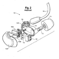
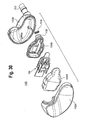
- a prior art earphone assembly 100 is shown in FIG. 2 .
- a first cover portion 102A and a second cover portion 102B form a housing for the internal components of the earphone.
- the housing contains a first balanced armature driver 104A and a second balanced armature driver 104B, a nozzle 112, and a coupling 118 for receiving a cable 116.
- the nozzle 112 mates with a sleeve 114, which is inserted into a user's ear.
- the cable 116 sends an audio signal to the drivers 104A, 104B, which create sound and output the sound into the nozzle 112.
- the nozzle 112 projects the sound directly into a user's ear canal.
- the balanced armature drivers 104A, 104B are held in place inside the first cover portion 102A and the second cover portion 102B by a set of ribs 106 located on the second cover portion 102B, a Poron seal 110, and a molded thermoplastic elastomer ("TPE") seal 108.
- the ribs 106 act to press the drivers 104A, 104B up against the Poron seal 110 and the TPE seal 108.
- the Poron seal 110 and the TPE seal 108 provide an acoustic seal between the nozzle 112 and the drivers 104A, 104B.
- a prior art hearing aid is disclosed in US 2006/0153418 .
- the hearing aid comprises a transducer comprising a sound outlet, the transducer being located in a housing of the hearing aid.
- a prior art earphone is disclosed in US 2009/0147981 .
- the earphone comprises an audio driver connected to an acoustic summation chamber connected to a nozzle.
- the present disclosure contemplates earphone driver assemblies.
- the following presents a simplified summary of the disclosure in order to provide a basic understanding of some aspects. It is not intended to identify key or critical elements of the invention or to delineate the scope of the invention.
- the following summary merely presents some concepts of the disclosure in a simplified form as a prelude to the more detailed description provided below.
- the present disclosure could be implemented in or in conjunction with the earphone assemblies, drivers, and methods disclosed in attorney docket nos. 010886.01321, titled “Earphone Driver and Method of Manufacture” and attorney docket no. 010886.01328, titled "Drive Pin Forming Method and Assembly for a Transducer”.
- the invention provides an earphone assembly comprising: an inner housing containing a balanced armature motor assembly, the inner housing comprising an inner cover portion and a spout base portion comprising a spout with a sound outlet, the spout comprising an o-ring and a recessed portion wherein the recessed portion receives the o-ring; an outer housing comprising an outer cover, and a primary case portion having a nozzle for transmitting sound, the primary case portion further comprising an internal recess, the nozzle extending from the internal recess wherein the internal recess receives the spout and the o-ring to form an acoustical seal between the spout and the nozzle to form a continuous passage to a user's ear canal.
- the balanced armature motor assembly may comprise a paddle, and the paddle may be acoustically sealed inside the inner housing.
- the nozzle may receive a sleeve adapted for placement into an ear canal of a user.
- the internal recess can comprise a counterbore for receiving the spout and the o-ring.
- the earphone assembly may comprise: an inner housing comprising a nozzle, configured to receive a sleeve for placement into a user's ear, and a balanced armature motor assembly, wherein the balanced armature motor assembly is mounted in the inner housing so as to form an acoustical seal between the inner housing and the balanced armature motor assembly; and an outer housing configured to receive the inner housing, wherein the nozzle of the inner housing extends through the outer housing.
- the inner housing can comprise a recess for receiving a paddle and at least one notch portion for receiving the pole piece.
- the inner housing may comprise a nozzle base and a cover. Alternatively one of the nozzle base or cover comprises a cavity housing the balanced armature motor assembly.
- the balanced armature motor assembly can comprise an armature, a pole piece containing an upper magnet and a lower magnet, a bobbin surrounded by a coil, a flex board mounted to the bobbin, and a drive pin, and the drive pin can be operatively connected to a paddle.
- the earphone assembly may comprise: an inner housing comprising a balanced armature motor assembly; wherein the balanced armature motor assembly is mounted in the inner housing so as to form an acoustical seal between the inner housing and the balanced armature motor assembly; and an outer housing comprising a nozzle configured to receive a sleeve for placement into a user's ear; wherein at least a portion of the inner housing is integrally formed together with the outer housing.
- the inner housing may comprise both a base portion formed together with the outer housing and an inner cover portion formed together with the outer housing.
- the inner housing may comprise a lid configured to be secured to the portion of the inner housing formed together with the outer housing.
- the invention provides a method of forming an earphone assembly comprising: joining an inner cover portion with a spout base portion having a spout to form an inner housing for housing a balanced armature motor assembly; forming the spout with a recessed portion; placing an o-ring in the recessed portion of the spout of the spout base portion; placing at least a portion of the spout and the o-ring into a recess in a primary case portion, the primary case portion further comprising a nozzle extending from the recess, the o-ring forming an acoustical seal between the spout and the nozzle to form a continuous passage to a user's ear canal; sealing an outer cover onto the primary case portion to form an outer housing, the outer housing containing the inner housing.
- the method may further comprise acoustically sealing a paddle to the spout base portion of the inner housing, and placing a sleeve onto the nozzle for placement into an ear canal of a user.
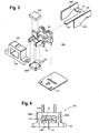
- a balanced armature motor assembly which generally consists of an armature 156, upper and lower magnets 158A, 158B, a pole piece 160, a bobbin 162, a coil 164, a drive pin 174, and a flex board 167.
- the magnets 158A, 158B can be secured to the pole piece 160 by one or more welds made between the magnets 158A, 158B and pole piece 160 while the magnets 158A, 158B are held into place by one or more glue dots 182.
- the flex board 167 is a flexible printed circuit board that mounts to the bobbin 162 and the free ends of the wire forming the coil 164 are secured to the flex board 167.
- the armature 156 is generally E-shaped from a top view. However, the armature 156 may have a U-shape or any other known, suitable shape.
- the armature has a flexible metal reed 166 which extends through the bobbin 162 and the coil 164 between the upper and lower magnets 158A, 158B.
- the armature 156 also has two outer legs 168A, 168B, lying generally parallel with each other and interconnected at one end by a connecting part 170. As illustrated in FIG. 4 , the reed 166 is positioned within an air gap 172 formed by the magnets 158A, 158B.
- the two outer armature legs 168A and 168B extend along the outer side along the bobbin 162, coil 164, and pole piece 160.
- the two outer armature legs 168A and 168B are affixed to the pole piece 160.
- the reed 166 can be connected to any paddle discussed herein, such as a paddle 252, shown in FIG. 5 , with the drive pin 174.
- the drive pin 174 can be formed of stainless steel wire or any other known suitable material.
- the electrical input signal is routed to the flex board 167 via a signal cable comprised of two conductors. Each conductor is terminated via a soldered connection to its respective pad on the flex board 167. Each of these pads is electrically connected to a corresponding lead on each end of the coil 164.
- signal current flows through the signal cable and into the coil's 164 windings, magnetic flux is induced into the soft magnetic reed 166 around which the coil 164 is wound.
- the signal current polarity determines the polarity of the magnetic flux induced in the reed 166.
- the free end of the reed is suspended between the two permanent magnets 158A, 158B.
- the magnetic axes of these two permanent magnets are both aligned perpendicular to the lengthwise axis of the reed 166.
- the lower face of the upper magnet 158A acts as a magnetic south pole while the upper face of the lower magnet 158B acts as a magnetic north pole.
- the free end of the reed 166 oscillates its behavior between that of a magnetic north pole and south pole, respectively.
- the free end of the reed 166 repels from the north-pole face of the lower magnet and attracts to the south-pole face of the upper magnet.
- the free end of the reed oscillates between north and south pole behavior, its physical location in the air gap 172 oscillates in kind, thus mirroring the waveform of the electrical input signal.
- the motion of the reed 166 by itself functions as an extremely inefficient acoustic radiator due to its minimal surface area and lack of an acoustic seal between its front and rear surfaces.
- the drive pin 174 is utilized to couple the mechanical motion of the free end of the reed to an acoustically sealed, lightweight paddle 152 of significantly larger surface area.
- the resulting acoustic volume velocity is then transmitted through the earphone nozzle 212 and ultimately into the user's ear canal, thus completing the transduction of the electrical input signal into the acoustical energy detected by the user.
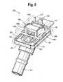
- FIGS. 5-9 depict an example of a balanced armature driver motor built into, or formed integral with the nozzle assembly 200.
- the balanced armature motor assembly 150 is built into the nozzle base 201.
- the nozzle base 201 is formed of a molded material, which may be rigid or somewhat resilient.
- the nozzle base 201 provides locating, mating, and resting features for subsequent sub-assemblies such as the paddle 252 and motor assembly 150 that mate to the nozzle base 201.
- a nozzle 212 is integrally formed with and projects from the nozzle base 201.
- the motor assembly 150 with the components discussed above mounts to a shelf 202 in the nozzle base 201.
- An outer rim 208 of the nozzle base 201 receives a cover 210 also formed of a molded material to form an inner housing.
- the inner housing can then be encased by an outer housing (not shown).
- the cover 210 can be secured to the outer rim 208 using any appropriate known method, such as gluing, mechanically fastened with clips, screws, mating parts, or snap-fit, etc.
- the nozzle base 201 is formed with a cutout or reservoir 234 for receiving the paddle 252 and has mating features for the pole piece 160 and the armature 156.
- the nozzle base comprises a substantially flat panel.
- a cavity 235 forms a portion of a front acoustic cavity in the transducer.
- the underside of the cover 210 forms a rear acoustic cavity in the transducer.
- the oscillation of the reed 166 through the drive pin 174 causes the paddle 252 to vibrate creating sound, which travels through port 219, shown in FIG. 6 in the nozzle base 201.
- the nozzle 212 then projects sound to the ear canal of the user through a sound port or opening in the end of the nozzle.
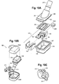
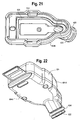
- FIGS. 10A-10C depict another example of a motor assembly 150 directly built into a box-shaped housing base 310 acting as a base part in the assembly 300.
- the assembly 300 includes a nozzle cover 301 with a nozzle 312 for outputting sound to a user's ear.
- the nozzle cover 301 is formed of a molded material and has a portion 303 adjacent to paddle 352.
- the paddle 352 and an outer rim portion 308 mount in a correspondingly shaped recess 307 in the base 310.
- the base 310 and the outer rim portion 308 can be joined using any known fastening method.
- the base 310 can also be formed of a molded material and can include a cutout 336 in the rear portion for receiving the flex board 167.
- the nozzle cover 301 and the base 310 form an enclosure or an inner housing for a balanced armature driver motor assembly 150 having the components discussed above.
- the nozzle cover 301 and the base 310 can be formed of a molded material.
- an outer cover 302A and a primary case portion 302B are assembled using any known fastening method to form an outer housing 302 enclosing the inner housing formed by the nozzle cover 301 and the base 310 to form an earphone assembly.
- a plastic sheath component 313 for a signal cable (not shown) can be mounted between the outer cover 302A and the primary case portion 302B.
- a sleeve (not shown) formed of foam, silicone, or other known suitable materials can be placed on the nozzle 312. The sleeve may be used to create a seal between the nozzle 312 and the listener's ear during use.
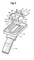
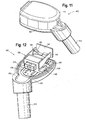
- FIGS. 11-15 depict another example of a balanced armature driver directly built into and integral with the nozzle assembly 400.
- the assembly 400 includes a nozzle base 401 with an integral nozzle 412, which can be formed of a molded material and configured to receive a sleeve, for placement into a user's ear canal to output sound to the user's ear.
- the nozzle base 401 provides locating, mating, and resting features for subsequent sub-assemblies such as the paddle 452 and motor assembly 150 that mate to the nozzle base 401. As shown in FIG.
- the nozzle base 401 also has a recess 434 with mating features for receiving a paddle 452 and a notch portion 414 for locating and mounting the pole piece 160 of the motor assembly 150 to the nozzle base 401.
- a lip or rim 408 is configured to receive the cover 410.
- the lip 408 and the cover 410 can be secured using any known fastening method.
- the cover 410 and the nozzle base 401 form an inner housing which can be enclosed by an outer housing (not shown).
- the nozzle base 401 is formed with a cutout or reservoir 434 for receiving the paddle 452.
- An additional cavity, (not shown, but similar to cavity 235 in FIG.
- the cover 410 forms a rear acoustic cavity in the transducer.
- the nozzle base 401 can also be provided with a cutout 436 in the rear portion for receiving the flex board 167.
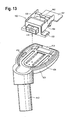
- FIGS. 16A and 16B depict a slight variation of the example shown in FIGS. 11-15 .
- the earphone assembly 500 has similar components to the example shown in FIGS. 11-15 (with like reference numerals depicting like components as those described in such figures).
- the assembly 500 includes a nozzle base 501 with integral nozzle 512 for receiving a sleeve and outputting sound to a user.
- the nozzle base 501 and a cover 510 form an enclosure or an inner housing for a motor assembly and can be secured using any known fastening method.
- the nozzle base 501 and the cover 510 can also be formed of a molded material.
- the nozzle base 501 additionally includes a recess 503 for receiving a projection 505 in an outer cover 502A for alignment and assembly purposes.
- the outer cover 502A and a primary case portion 502B mate to form an outer housing 502 enclosing the inner housing formed by the nozzle base 501 and the cover 510 to form an earphone assembly.
- the outer cover 502A and a primary case portion 502B can be joined together with the nozzle base 501 and cover 510 using any known fastening method.
- a front acoustic cavity consisting of a recess volume in the nozzle base that is under the paddle coupled directly to a geometric volume consisting of the internal features within the integral nozzle all within the same part has the benefit of a consistent geometric shape and frequency response resulting from the acoustic cavity. This also aids in reducing acoustic leaking and reducing the number of components for providing the acoustic seal resulting in a simplified design.
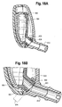
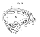
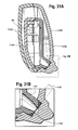
- FIGS. 17-25 depict an embodiment earphone assembly 600.
- the assembly comprises an outer cover 602A and a primary case portion 602B, which when joined together by any known fastening method form an outer housing 602 for the earphone assembly 600.
- an inner housing 604 containing a balanced armature motor assembly 150 similar to the motor assemblies described in reference to the other examples herein (with like reference numerals referring to like components thereof).
- the inner housing 604 is formed of an inner cover portion 604A and a spout base portion 604B. During assembly, the inner cover portion 604A and the spout base portion 604B are sealed together using any known fastening method.
- the inner housing 604 encloses the motor assembly 150.
- the spout base portion 604B includes a spout 620 having a recessed portion 622 for receiving an o-ring 624. As shown best in FIG. 21 , the spout base portion 604B also includes an internal recess 626 for locating and receiving a paddle 652. Additionally, the spout base portion 604B also has a notch portion 614 for locating and mounting the pole piece 160 of the motor assembly 150 to the spout base portion 604B. During assembly, the paddle 152 is acoustically sealed to the spout base portion 604B.
- the primary case portion 602B also includes an integral nozzle 612.
- the interior portion of the nozzle 612 includes an internal recess 628 for receiving the spout 620 and o-ring 624.
- a cross section of both the outer housing 602 and the inner housing 604 when coupled is depicted in FIGS. 18A and 18B .
- the spout together with the o-ring 624 creates an acoustical seal within the recess 628 of the outer housing 602.
- the outer housing 602 can be configured to additionally impart axial forces on the inner housing 604 so as to cause the spout 620 to maintain its acoustic seal with the nozzle 612.
- the spout 620 and the nozzle 612 form a continuous sound passage to a user's ear canal.
- the primary case portion 602B also includes a coupling 618 for receiving a signal cable (not shown).
- the nozzle 612 mates with a sleeve (not shown) placed over the end of the nozzle 612, which is inserted into a user's ear.
- a sleeve (not shown) placed over the end of the nozzle 612, which is inserted into a user's ear.
- the motor assembly 150 receives a signal, it in turn creates sound and outputs the sound into the spout 620. Because the spout is placed in the recess 628 within the nozzle 612, the sound travels directly from the spout into the nozzle 612, which projects the sound into a user's ear canal.
- the pole piece 160 and the bobbin 162 and coil 164 act as a locating and support mechanism for assembling the motor assembly 150 to the spout base portion 604B.
- the pole piece 160 in conjunction with a center post in the bobbin act as a support bracket, which functions as a mounting and support mechanism for the entire motor assembly 150 to mate locating features in the spout base portion 604B.
- the spout o-ring configuration provides a symmetrical "non-handed" design and provides for a higher quality and accuracy in manufacturing. More specifically, while the outer housing 602 must be specifically manufactured to be either a left ear housing or a right ear housing, the inner housing 604 may be configured to be universal, and capable of being mounted inside either a "left handed" outer housing 602 or a "right handed” outer housing 602. This design can also reduce the overall stress on the motor assembly by reducing the amount of internal forces placed in the motor housing and leads to improved shock absorption. It also allows for a more compact driver design. The design is also platformable and can be used in other earphone designs and devices.
- the spout o-ring sealing method maintains a complete seal without any preloads necessary on the driver.
- the drivers are preloaded against the ribs 106 of the outer housing 102 to provide the acoustic seal.
- the ribs 106 provide a compressive force on the armatures 104A, 104B so as maintain the acoustic seal by pressing the armatures 104A, 104B up against the Poron seal 110, the TPE seal 108, and the nozzle 112.
- the spout o-ring design also optimizes the part break up of the overall earphone transducer design. Because of the way the design breaks up into sub-assemblies and parts, it maximizes open processing surfaces, minimizes the number of necessary parts, minimizes tolerance stack up, and undesirable part interactions. This improves product quality by optimizing the parts locating and fitting together within the transducer in a robust fashion during assembly in a manufacturing and reduces the likelihood of acoustic leaking between the front and rear acoustic cavities within the transducer. Having a base part with locating features also enables Z-axis "pick and place" automation of sub-assemblies that mate to the spouted base portion in manufacturing.
- the nozzle bases can be placed into a holding carrier that moves through an assembly line where additional sub-assemblies such as the paddle, motor assembly, and cover parts can be picked and placed with robot vacuum arms.
- Z-axis "pick and place” means that gravity works to have the parts fall into their seated position without the need for additional hold down mechanisms.
- mating sub-assemblies can be added to the spout base portion without taking the base portion out of a holding fixture during transducer assembly in a manufacturing environment, resulting in less handling and reorientation of the work parts during manufacturing.
- the design also simplifies the mating interface between the spout base portion to the primary case portion by using an o-ring concentric sealing interface consisting of a recess or groove in a spout and a counterbore shaped collector. Additionally, the spout is not "handed" thus enabling the transducer assembly to be used in both a left earphone and a right earphone.
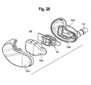
- FIG. 26 depicts an example earphone assembly 700.
- the assembly 700 is similar to the assembly 600 shown in FIGS. 17-25 , however, instead of having a spout base portion 604B, a base portion 704B is formed integral with the primary case portion 702B having a nozzle 712.
- the inner housing is formed of an inner cover portion 704A and a base portion 704B and contains the balanced armature driver motor assembly 150.
- the inner cover portion 704A and the base portion 704B are sealed together using any known fastening method and the outer cover 702A encloses the inner housing formed by the inner cover portion 704A and the base portion 704B.
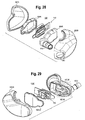
- FIGS. 27A and 27B depict an alternative earphone assembly 800.
- the assembly 800 is similar to the assembly 600 shown in FIGS. 17-25 , however, instead of having a spout base portion 604B, a base portion 804B is formed integral with the primary case portion 802B having a nozzle 812. Furthermore, instead of having an inner cover portion 604A separate from an outer cover 602A, an inner cover portion 804A is formed integral with an outer cover 802A.
- the motor assembly 150 is mounted in the inner cover portion 804A.
- the inner cover portion 804A, the base portion 804B are sealed together along with the outer cover portion 802A and the primary case portion 802B using any known fastening method to form the assembly 800.
- FIG. 28 depicts an alternative earphone assembly 900.
- the assembly 900 is similar to the assembly 600 shown in FIGS. 17-25 , however, instead of having a spout base portion 604B, a base portion 904B is formed with an integral nozzle 912 that extends through a hole 903 in a primary case portion 902B.
- the nozzle 912 is part of the base portion 904B rather than the primary case portion 902B.
- the balanced armature driver motor 150 is secured to the base portion 904B and an inner cover portion 904A is secured to the base portion 904B using any known fastening method.
- the base portion 904B can then be secured to the primary case portion 902B such that the nozzle 912 extends through hole 903.
- the outer cover 902A can be secured to the primary case portion 902B.
- FIG. 29 depicts an alternative earphone assembly 1000.
- the assembly 1000 is similar to the assembly 600 shown in FIGS. 17-25 , however, instead of having a spout base portion 604B, a base portion 1004B is formed integral with the primary case portion 1002B having a nozzle 1012. Additionally, the inner housing is formed of an inner lid portion 1004A and the base portion 1004B, which contains the balanced armature driver motor assembly 150. The inner lid portion 1004 is relatively flat. During assembly, the inner lid portion 1004A and the base portion 1004B are sealed together using any known fastening method, and the outer cover 1002A encloses the inner housing formed by the inner lid portion 1004A and the base portion 1004B.
- FIGS. 30-31B depict an alternative earphone assembly 1100.
- the assembly 1100 is similar to the assembly 600 shown in FIGS. 17-25 , however, the spout 1120 does not include a recessed portion for receiving the o-ring 1124 to create a radial force on the spout 1120. Rather as shown in FIG. 31B , the o-ring 1124 is sandwiched between an outer tapered rim portion of the spout 1120 and a top portion of the primary case portion 1102B near recess 1128.
- the assembly comprises an outer cover 1102A and a primary case portion 1102B having a nozzle 1112 configured to receive a sleeve.
- the primary case portion 1102B and the outer cover 1102A are joined together by any known fastening method to form an outer housing for the earphone assembly 1100.
- the inner housing is formed of an inner cover portion 1104A and a spout base portion 1104B and is placed within the outer housing and contains a balanced armature motor assembly 150 similar to the motor assemblies described in reference to the other examples herein.
- the inner cover portion 1104A and the spout base portion 1104B are sealed together using any known fastening method, and the inner housing encloses the motor assembly 150.
- the spout 1120 on spout base portion 1104B is then placed into contact with the o-ring 1124 which is sandwiched into recess 1128 to create an axial force on the inner housing such that an acoustic seal is formed between the inner housing components (inner cover portion 1104A, spout base portion 1104B) and the outer housing components (outer cover 1102A, primary case portion 1102B) and the inner housing is maintained in position.
Landscapes
- Engineering & Computer Science (AREA)
- Physics & Mathematics (AREA)
- Acoustics & Sound (AREA)
- Signal Processing (AREA)
- Manufacturing & Machinery (AREA)
- Electromagnetism (AREA)
- Electrostatic, Electromagnetic, Magneto- Strictive, And Variable-Resistance Transducers (AREA)
- Headphones And Earphones (AREA)
Applications Claiming Priority (2)
| Application Number | Priority Date | Filing Date | Title |
|---|---|---|---|
| US12/833,651 US8548186B2 (en) | 2010-07-09 | 2010-07-09 | Earphone assembly |
| PCT/US2011/042575 WO2012006211A1 (en) | 2010-07-09 | 2011-06-30 | Earphone assembly |
Publications (2)
| Publication Number | Publication Date |
|---|---|
| EP2591612A1 EP2591612A1 (en) | 2013-05-15 |
| EP2591612B1 true EP2591612B1 (en) | 2015-08-26 |
Family
ID=44532079
Family Applications (1)
| Application Number | Title | Priority Date | Filing Date |
|---|---|---|---|
| EP11741715.4A Not-in-force EP2591612B1 (en) | 2010-07-09 | 2011-06-30 | Earphone assembly |
Country Status (8)
| Country | Link |
|---|---|
| US (1) | US8548186B2 (ja) |
| EP (1) | EP2591612B1 (ja) |
| JP (1) | JP5793566B2 (ja) |
| KR (1) | KR101829419B1 (ja) |
| CN (1) | CN102986245B (ja) |
| SG (1) | SG186794A1 (ja) |
| TW (1) | TWI468028B (ja) |
| WO (1) | WO2012006211A1 (ja) |
Families Citing this family (38)
| Publication number | Priority date | Publication date | Assignee | Title |
|---|---|---|---|---|
| US8249287B2 (en) | 2010-08-16 | 2012-08-21 | Bose Corporation | Earpiece positioning and retaining |
| US8897463B2 (en) * | 2010-05-26 | 2014-11-25 | Jerry Harvey | Dual high frequency driver canalphone system |
| US8538061B2 (en) * | 2010-07-09 | 2013-09-17 | Shure Acquisition Holdings, Inc. | Earphone driver and method of manufacture |
| US8737669B2 (en) | 2011-07-28 | 2014-05-27 | Bose Corporation | Earpiece passive noise attenuating |
| US9210497B2 (en) * | 2012-09-06 | 2015-12-08 | Shure Acquisition Holdings, Inc. | Electrostatic earphone |
| JP5907274B2 (ja) * | 2012-09-11 | 2016-04-26 | オンキヨー株式会社 | イヤホン装置 |
| US9426558B2 (en) | 2012-09-14 | 2016-08-23 | Puma SE | Earphone with chassis enclosure |
| US9055366B2 (en) | 2013-01-22 | 2015-06-09 | Apple Inc. | Multi-driver earbud |
| USD752026S1 (en) * | 2014-12-30 | 2016-03-22 | Shenzhen Soundsoul Information Technology Co. Ltd. | Headphone |
| US10154331B2 (en) | 2015-02-10 | 2018-12-11 | Phazon Inc. | Wireless earbud |
| US9706290B2 (en) | 2015-02-27 | 2017-07-11 | Apple Inc. | Balanced armature based valve |
| USD777710S1 (en) * | 2015-07-22 | 2017-01-31 | Doppler Labs, Inc. | Ear piece |
| JP2017059988A (ja) * | 2015-09-16 | 2017-03-23 | アルプス電気株式会社 | 発音装置 |
| USD797079S1 (en) | 2015-10-20 | 2017-09-12 | Phazon Inc. | Wireless earbud |
| US9774941B2 (en) | 2016-01-19 | 2017-09-26 | Apple Inc. | In-ear speaker hybrid audio transparency system |
| CN108496373B (zh) * | 2016-02-01 | 2020-08-21 | 索尼公司 | 声音输出装置 |
| US10091576B2 (en) * | 2016-02-16 | 2018-10-02 | Campfire Audio Llc | In-ear monitor |
| USD801951S1 (en) * | 2016-04-20 | 2017-11-07 | Shenzhen Aerospace Golden Shine Technology Co., Ltd | Earphone |
| FR3054766B1 (fr) * | 2016-07-29 | 2019-07-12 | Custom Art - Piotr Granicki | Ensemble a haut-parleur a armature equilibree ameliore |
| US10469940B2 (en) | 2016-09-23 | 2019-11-05 | Apple Inc. | Valve for acoustic port |
| US11012786B2 (en) | 2016-10-17 | 2021-05-18 | Knowles Electronics, Llc | Armature-based acoustic receiver having improved output and method |
| USD806687S1 (en) * | 2016-11-11 | 2018-01-02 | Tunes, LLC | Headphones |
| US9860645B1 (en) | 2017-01-05 | 2018-01-02 | Ryan C. Tsui | Multi-driver air-tube earphone |
| KR101901408B1 (ko) * | 2017-04-20 | 2018-09-28 | 주식회사 이엠텍 | 개선된 후방 구조를 가지는 아마추어 스피커 |
| CN107071666A (zh) * | 2017-05-08 | 2017-08-18 | 佛山市川东磁电股份有限公司 | 一种直线移动双位稳态电磁开关 |
| USD852782S1 (en) * | 2017-06-26 | 2019-07-02 | Kanoa Inc. | Ear bud headset |
| US11582558B2 (en) | 2017-07-14 | 2023-02-14 | Knowles Electronics, Llc | Acoustic receiver and method of making same |
| DE102018221577A1 (de) | 2017-12-30 | 2019-07-04 | Knowles Electronics, Llc | Elektroakustischer wandler mit verbessertem stoss-schutz |
| USD868750S1 (en) * | 2018-05-07 | 2019-12-03 | Bin Zheng | Wireless earphone |
| USD864167S1 (en) * | 2018-07-02 | 2019-10-22 | Shenzhen Meilianfa Technology Co., Ltd. | Earphone |
| TWI687105B (zh) * | 2018-12-20 | 2020-03-01 | 英屬開曼群島商康而富控股股份有限公司 | 利用金屬料帶成型的內模組件 |
| US11076247B2 (en) * | 2018-12-31 | 2021-07-27 | Knowles Electronics, Llc | Acoustic receiver with b-stage seal and method of making same |
| US10924838B1 (en) * | 2019-09-11 | 2021-02-16 | Bose Corporation | Audio device |
| US11159890B2 (en) | 2019-10-18 | 2021-10-26 | Knowles Electronics, Llc | Acoustic receiver |
| KR102203295B1 (ko) * | 2019-12-11 | 2021-01-14 | 부전전자 주식회사 | 그릴 일체형 로우패스 필터 및 이를 포함하는 스피커 |
| USD975685S1 (en) * | 2021-08-05 | 2023-01-17 | Dreamus Company | Earphone |
| US11659337B1 (en) | 2021-12-29 | 2023-05-23 | Knowles Electronics, Llc | Balanced armature receiver having improved shock performance |
| USD1025007S1 (en) * | 2022-06-16 | 2024-04-30 | Audiolineout Llc | Pair of earphones |
Family Cites Families (126)
| Publication number | Priority date | Publication date | Assignee | Title |
|---|---|---|---|---|
| US2325590A (en) | 1940-05-11 | 1943-08-03 | Sonotone Corp | Earphone |
| US2430229A (en) | 1943-10-23 | 1947-11-04 | Zenith Radio Corp | Hearing aid earpiece |
| US2521414A (en) | 1947-12-01 | 1950-09-05 | Mayer B A Schier | Adjustable auditory insert |
| US2808468A (en) | 1952-02-07 | 1957-10-01 | Sonotone Corp | Magnetic insert earphone and inserts therefor |
| US2971065A (en) | 1956-10-10 | 1961-02-07 | Sonotone Corp | Ear insert hearing aid |
| US3068954A (en) | 1958-02-10 | 1962-12-18 | Charles W Strzalkowski | Hearing aid apparatus and method |
| US3265819A (en) | 1963-05-15 | 1966-08-09 | Sonotone Corp | Ear insert hearing aid |
| USRE26258E (en) | 1964-04-02 | 1967-08-29 | In-the-ear hearing aid | |
| GB1119445A (en) | 1965-03-26 | 1968-07-10 | Danavox Internat A S | Hearing aid |
| US3374318A (en) | 1965-04-01 | 1968-03-19 | Dahlberg Electronics | Wax guard for hearing aids |
| US3312789A (en) | 1966-02-03 | 1967-04-04 | Dahlberg Electronics | Ear canal hearing aid |
| NL7613904A (en) | 1976-12-15 | 1978-06-19 | Harmen Broersma | Transducer with electromagnetic converter for miniature hearing aid - has chamber with partition partly of foil with hole for push rod and damping |
| US4311206A (en) | 1978-05-15 | 1982-01-19 | Johnson Rubein V | Hearing aid ear mold with improved discrimination |
| DE2923865C2 (de) | 1979-06-13 | 1981-09-17 | Thyssen Edelstahlwerke AG, 4000 Düsseldorf | Verfahren zum Zusammensetzen der Einzelteile eines streufeldarmen Dauermagnetsystems für Lautsprecher |
| US4295066A (en) | 1980-01-11 | 1981-10-13 | Cts Corporation | Electromagnetic actuator |
| US4375016A (en) | 1980-04-28 | 1983-02-22 | Qualitone Hearing Aids Inc. | Vented ear tip for hearing aid and adapter coupler therefore |
| DE3023871A1 (de) | 1980-06-26 | 1982-01-14 | Robert Bosch Gmbh, 7000 Stuttgart | Hoergeraet |
| US4407389A (en) | 1981-01-19 | 1983-10-04 | Johnson Rubein V | Vented acoustic ear mold for hearing aids |
| US4443668A (en) | 1981-03-23 | 1984-04-17 | Warren James C | Earplug mounting device with audio passageway |
| JPH0312000Y2 (ja) * | 1981-04-20 | 1991-03-22 | ||
| US4420657A (en) | 1981-10-29 | 1983-12-13 | Acs Communications, Inc. | Adjustable headset |
| US4473722B1 (en) | 1982-06-07 | 1995-06-20 | Knowles Electronics Co | Electroacoustic transducers |
| US4592370A (en) | 1982-09-27 | 1986-06-03 | Minnesota Mining And Manufacturing Company | Ear canal electrode for auditory testing |
| US4532649A (en) | 1983-07-03 | 1985-07-30 | Gaspare Bellafiore | Hearing aid |
| US4520236A (en) | 1983-11-30 | 1985-05-28 | Nu-Bar Electronics | Sound transfer from a hearing aid to the human ear drum |
| GB2155276B (en) | 1984-03-02 | 1987-10-21 | Beltone Electronics Corp | Hearing aid ear piece with wax guard |
| AT380762B (de) | 1984-08-06 | 1986-07-10 | Viennatone Gmbh | Hoergeraet |
| IT209301Z2 (it) | 1984-12-15 | 1988-09-20 | Siemens Ag | Protesi uditiva. |
| DE3540579A1 (de) | 1985-11-15 | 1987-05-27 | Toepholm & Westermann | Im-ohr-hoergeraet |
| US4870688A (en) | 1986-05-27 | 1989-09-26 | Barry Voroba | Mass production auditory canal hearing aid |
| US4677408A (en) | 1986-07-28 | 1987-06-30 | G. General Electro-Components, Inc. | Solenoid coil connection |
| DE3723275A1 (de) | 1986-09-25 | 1988-03-31 | Temco Japan | Ohrmikrofon |
| US5002151A (en) | 1986-12-05 | 1991-03-26 | Minnesota Mining And Manufacturing Company | Ear piece having disposable, compressible polymeric foam sleeve |
| US4870689A (en) | 1987-04-13 | 1989-09-26 | Beltone Electronics Corporation | Ear wax barrier for a hearing aid |
| DE8713369U1 (ja) | 1987-10-05 | 1989-02-09 | Siemens Ag, 1000 Berlin Und 8000 Muenchen, De | |
| US5131128A (en) | 1987-10-14 | 1992-07-21 | Gn Danavox A/S | Protection element for all-in-the-ear hearing aid and tool for use in the replacement hereof |
| US4867267A (en) | 1987-10-14 | 1989-09-19 | Industrial Research Products, Inc. | Hearing aid transducer |
| US4969534A (en) | 1988-08-08 | 1990-11-13 | Minnesota Mining And Manufacturing Company | Hearing aid employing a viscoelastic material to adhere components to the casing |
| JP2546271Y2 (ja) | 1988-12-12 | 1997-08-27 | ソニー株式会社 | 電気音響変換器 |
| US4956868A (en) | 1989-10-26 | 1990-09-11 | Industrial Research Products, Inc. | Magnetically shielded electromagnetic acoustic transducer |
| GB8928899D0 (en) | 1989-12-21 | 1990-02-28 | Knowles Electronics Co | Coil assemblies |
| WO1994025957A1 (en) | 1990-04-05 | 1994-11-10 | Intelex, Inc., Dba Race Link Communications Systems, Inc. | Voice transmission system and method for high ambient noise conditions |
| US5068901A (en) | 1990-05-01 | 1991-11-26 | Knowles Electronics, Inc. | Dual outlet passage hearing aid transducer |
| US5319163A (en) | 1990-06-07 | 1994-06-07 | Scott Robert T | Waterproof earmold-to-earphone adapter |
| DE69233156T2 (de) | 1991-01-17 | 2004-07-08 | Adelman, Roger A. | Verbessertes hörgerät |
| US5193116A (en) | 1991-09-13 | 1993-03-09 | Knowles Electronics, Inc. | Hearing and output transducer with self contained amplifier |
| US5682020A (en) | 1991-12-09 | 1997-10-28 | Oliveira; Robert J. | Sealing of hearing aid to ear canal |
| US5220612A (en) | 1991-12-20 | 1993-06-15 | Tibbetts Industries, Inc. | Non-occludable transducers for in-the-ear applications |
| US5299176A (en) | 1991-12-20 | 1994-03-29 | Tibbetts Industries, Inc. | Balanced armature transducers with transverse gap |
| US5887070A (en) | 1992-05-08 | 1999-03-23 | Etymotic Research, Inc. | High fidelity insert earphones and methods of making same |
| DK170012B1 (da) | 1992-09-10 | 1995-04-24 | Peer Kuhlmann | Øremikrofon til indsætning i øre i forbindelse med mobiltelefoner og mobilradio |
| US5647013C1 (en) | 1992-10-29 | 2001-05-08 | Knowles Electronics Co | Electroacoustic transducer |
| USD360691S (en) | 1993-09-01 | 1995-07-25 | Knowles Electronics, Inc. | Hearing aid receiver |
| USD360949S (en) | 1993-09-01 | 1995-08-01 | Knowles Electronics, Inc. | Hearing aid receiver |
| USD360948S (en) | 1993-09-01 | 1995-08-01 | Knowles Electronics, Inc. | Hearing aid receiver |
| US5655026A (en) | 1993-12-23 | 1997-08-05 | Otto Engineering, Inc. | Ear receiver |
| US5692059A (en) | 1995-02-24 | 1997-11-25 | Kruger; Frederick M. | Two active element in-the-ear microphone system |
| US5661420A (en) | 1995-03-08 | 1997-08-26 | Etymotic Research, Inc. | Mounting configuration for monolithic integrated circuit |
| US5721783A (en) | 1995-06-07 | 1998-02-24 | Anderson; James C. | Hearing aid with wireless remote processor |
| DE19525865A1 (de) | 1995-07-15 | 1997-01-16 | Sennheiser Electronic | Hörhilfe mit einem elektrodynamischen Schallwandler |
| NL1000878C2 (nl) | 1995-07-24 | 1997-01-28 | Microtronic Nederland Bv | Transducer. |
| NL1000880C2 (nl) | 1995-07-24 | 1997-01-28 | Microtronic Nederland Bv | Transducer. |
| USD377796S (en) | 1995-09-13 | 1997-02-04 | Sony Corporation | Earphone combined with microphone |
| US5753870A (en) | 1995-10-23 | 1998-05-19 | Schlaegel; Norman D. | Continuous flow earmold tubing connector with a filter |
| US5687244A (en) | 1996-03-28 | 1997-11-11 | Stanton Magnetics, Inc. | Bone conduction speaker and mounting system |
| NL1004877C2 (nl) | 1996-12-23 | 1998-08-03 | Microtronic Nederland Bv | Elektroakoestische transducent. |
| US6041131A (en) | 1997-07-09 | 2000-03-21 | Knowles Electronics, Inc. | Shock resistant electroacoustic transducer |
| JP3314149B2 (ja) * | 1997-11-12 | 2002-08-12 | リオン株式会社 | 内装型イヤホンの取付構造 |
| US6205227B1 (en) | 1998-01-31 | 2001-03-20 | Sarnoff Corporation | Peritympanic hearing instrument |
| US5960093A (en) | 1998-03-30 | 1999-09-28 | Knowles Electronics, Inc. | Miniature transducer |
| DE19821860A1 (de) | 1998-05-15 | 1999-11-18 | Nokia Deutschland Gmbh | Treiber für flaches Klangpaneel |
| US6137889A (en) | 1998-05-27 | 2000-10-24 | Insonus Medical, Inc. | Direct tympanic membrane excitation via vibrationally conductive assembly |
| NL1011733C1 (nl) | 1999-04-06 | 2000-10-09 | Microtronic Nederland Bv | Elektroakoestische transducent met een membraan en werkwijze voor het bevestigen van een membraan in een dergelijke transducent. |
| USD468299S1 (en) | 1999-05-10 | 2003-01-07 | Peter V. Boesen | Communication device |
| US6658134B1 (en) | 1999-08-16 | 2003-12-02 | Sonionmicrotronic Nederland B.V. | Shock improvement for an electroacoustic transducer |
| WO2001026413A2 (en) | 1999-10-07 | 2001-04-12 | Knowles Electronics, Llc | Electro-acoustic transducer with resistance to shock-waves |
| DE19954880C1 (de) | 1999-11-15 | 2001-01-25 | Siemens Audiologische Technik | Elektromagnetischer Wandler zur Schallerzeugung in Hörhilfen, insbesondere miniaturisierten elektronischen Hörgeräten |
| US7164776B2 (en) | 2000-01-07 | 2007-01-16 | Knowles Electronics, Llc. | Vibration balanced receiver |
| JP4260333B2 (ja) | 2000-03-16 | 2009-04-30 | スター精密株式会社 | 電気音響変換器 |
| EP1302092A2 (en) | 2000-05-24 | 2003-04-16 | Sonionmicrotronic Nederland B.V. | An assembly comprising an electrical element |
| US7050602B2 (en) | 2000-08-14 | 2006-05-23 | Knowles Electronics Llc. | Low capacitance receiver coil |
| USD453119S1 (en) | 2000-11-14 | 2002-01-29 | Star Micronics Co., Ltd. | Audible signal for alarms |
| US7103196B2 (en) | 2001-03-12 | 2006-09-05 | Knowles Electronics, Llc. | Method for reducing distortion in a receiver |
| JP2002300698A (ja) | 2001-04-02 | 2002-10-11 | Star Micronics Co Ltd | レシーバおよび携帯用通信機器 |
| EP1248496A3 (en) | 2001-04-04 | 2005-11-02 | Sonionmicrotronic Nederland B.V. | Aucoustic receiver having improved mechanical suspension |
| US6727789B2 (en) * | 2001-06-12 | 2004-04-27 | Tibbetts Industries, Inc. | Magnetic transducers of improved resistance to arbitrary mechanical shock |
| USD468300S1 (en) | 2001-06-26 | 2003-01-07 | Peter V. Boesen | Communication device |
| USD468301S1 (en) | 2001-08-09 | 2003-01-07 | Star Micronics Co., Ltd. | Earphone |
| JP3768431B2 (ja) | 2001-10-31 | 2006-04-19 | スター精密株式会社 | 挿入型イヤホン |
| US7190803B2 (en) | 2002-04-09 | 2007-03-13 | Sonion Nederland Bv | Acoustic transducer having reduced thickness |
| US7206425B2 (en) | 2003-01-23 | 2007-04-17 | Adaptive Technologies, Inc. | Actuator for an active noise control system |
| USD490399S1 (en) | 2003-02-14 | 2004-05-25 | Star Micronics Co., Ltd. | Earphone with microphone |
| CN1771762A (zh) * | 2003-03-03 | 2006-05-10 | 舒尔.阿奎西什控股公司 | 具有隔音入耳式驱动器的头戴式通信送受话器 |
| US7415125B2 (en) | 2003-05-09 | 2008-08-19 | Knowles Electronics, Llc | Apparatus and method for creating acoustic energy in a receiver assembly with improved diaphragms-linkage arrangement |
| US7024010B2 (en) | 2003-05-19 | 2006-04-04 | Adaptive Technologies, Inc. | Electronic earplug for monitoring and reducing wideband noise at the tympanic membrane |
| TWM245708U (en) * | 2003-11-26 | 2004-10-01 | Wintecronics Ltd | Plug-in speakerphone and communication apparatus having the plug-in speakerphone |
| US7321664B2 (en) | 2004-01-13 | 2008-01-22 | Sonionmicrotronic Nederland B.V. | Receiver having an improved bobbin |
| JP2005278015A (ja) | 2004-03-26 | 2005-10-06 | Star Micronics Co Ltd | イヤホン |
| US7362878B2 (en) | 2004-06-14 | 2008-04-22 | Knowles Electronics, Llc. | Magnetic assembly for a transducer |
| JP2006033417A (ja) * | 2004-07-16 | 2006-02-02 | Rion Co Ltd | 内装型イヤホンの取付構造 |
| US7242788B2 (en) | 2004-08-16 | 2007-07-10 | Hpv Technologies, Llc | Securing magnets in high-efficiency planar magnetic transducers |
| US7317806B2 (en) | 2004-12-22 | 2008-01-08 | Ultimate Ears, Llc | Sound tube tuned multi-driver earpiece |
| US7194103B2 (en) | 2004-12-22 | 2007-03-20 | Ultimate Ears, Llc | In-ear monitor with hybrid diaphragm and armature design |
| US7194102B2 (en) | 2004-12-22 | 2007-03-20 | Ultimate Ears, Llc | In-ear monitor with hybrid dual diaphragm and single armature design |
| US7263195B2 (en) | 2004-12-22 | 2007-08-28 | Ultimate Ears, Llc | In-ear monitor with shaped dual bore |
| US7529379B2 (en) | 2005-01-04 | 2009-05-05 | Motorola, Inc. | System and method for determining an in-ear acoustic response for confirming the identity of a user |
| ATE515897T1 (de) | 2005-01-10 | 2011-07-15 | Sonion Nederland Bv | Hörgerät mit miniaturlautsprecher |
| EP1878305B1 (en) | 2005-03-28 | 2012-10-03 | Knowles Electronics, LLC | Acoustic assembly for a transducer |
| US7489794B2 (en) | 2005-09-07 | 2009-02-10 | Ultimate Ears, Llc | Earpiece with acoustic vent for driver response optimization |
| JP4210677B2 (ja) * | 2005-09-08 | 2009-01-21 | リオン株式会社 | 電気音響変換器及びこれを用いた補聴器 |
| US20070104340A1 (en) | 2005-09-28 | 2007-05-10 | Knowles Electronics, Llc | System and Method for Manufacturing a Transducer Module |
| WO2007089845A2 (en) | 2006-01-30 | 2007-08-09 | Etymotic Research, Inc. | Insert earphone using a moving coil driver |
| US8031900B2 (en) | 2006-02-27 | 2011-10-04 | Logitech International, S.A. | Earphone ambient eartip |
| US8208674B2 (en) | 2006-05-23 | 2012-06-26 | Rh Lyon Corp | Squeeze-stretch driver for earphone and the like |
| US8170249B2 (en) | 2006-06-19 | 2012-05-01 | Sonion Nederland B.V. | Hearing aid having two receivers each amplifying a different frequency range |
| USD567217S1 (en) | 2006-08-18 | 2008-04-22 | Star Micronics Co., Ltd. | Earphone |
| JP4921197B2 (ja) * | 2007-02-06 | 2012-04-25 | スター精密株式会社 | 挿入型イヤホン |
| US8194911B2 (en) | 2007-03-27 | 2012-06-05 | Logitech International, S.A. | Earphone integrated eartip |
| JP5167355B2 (ja) | 2007-07-23 | 2013-03-21 | エイシアス テクノロジーズ, エルエルシー | ダイアフォニック音響変換連結器およびイヤホン |
| US8135163B2 (en) | 2007-08-30 | 2012-03-13 | Klipsch Group, Inc. | Balanced armature with acoustic low pass filter |
| DE102008049932A1 (de) | 2007-10-02 | 2009-05-28 | Phitek Systems Ltd. | Bauteil für Kopfhörer mit Geräuschunterdrückung |
| JP2009153103A (ja) * | 2007-10-02 | 2009-07-09 | Phitek Systems Ltd | ノイズ低減イヤホン用の構成部分 |
| US8447059B2 (en) | 2007-10-31 | 2013-05-21 | Thx Ltd | Earphone device |
| US8238596B2 (en) | 2007-12-10 | 2012-08-07 | Klipsch Group, Inc. | In-ear headphones |
| EP2101512B1 (en) | 2008-03-12 | 2012-07-18 | AKG Acoustics GmbH | In-ear earphone with multiple transducers |
| US20090296971A1 (en) * | 2008-05-29 | 2009-12-03 | Siemens Hearing Instruments, Inc. | Hearing Instrument Receiver With Improved Low-Frequency Efficiency |
-
2010
- 2010-07-09 US US12/833,651 patent/US8548186B2/en active Active
-
2011
- 2011-06-30 CN CN201180033981.4A patent/CN102986245B/zh active Active
- 2011-06-30 KR KR1020137003344A patent/KR101829419B1/ko active IP Right Grant
- 2011-06-30 SG SG2012094520A patent/SG186794A1/en unknown
- 2011-06-30 EP EP11741715.4A patent/EP2591612B1/en not_active Not-in-force
- 2011-06-30 WO PCT/US2011/042575 patent/WO2012006211A1/en active Application Filing
- 2011-06-30 JP JP2013518703A patent/JP5793566B2/ja not_active Expired - Fee Related
- 2011-07-08 TW TW100124313A patent/TWI468028B/zh not_active IP Right Cessation
Also Published As
| Publication number | Publication date |
|---|---|
| KR20130041196A (ko) | 2013-04-24 |
| TW201208400A (en) | 2012-02-16 |
| CN102986245A (zh) | 2013-03-20 |
| KR101829419B1 (ko) | 2018-02-19 |
| JP2013534115A (ja) | 2013-08-29 |
| TWI468028B (zh) | 2015-01-01 |
| JP5793566B2 (ja) | 2015-10-14 |
| WO2012006211A1 (en) | 2012-01-12 |
| SG186794A1 (en) | 2013-02-28 |
| US20120008814A1 (en) | 2012-01-12 |
| US8548186B2 (en) | 2013-10-01 |
| EP2591612A1 (en) | 2013-05-15 |
| CN102986245B (zh) | 2016-06-01 |
Similar Documents
| Publication | Publication Date | Title |
|---|---|---|
| EP2591612B1 (en) | Earphone assembly | |
| US7822218B2 (en) | Electroacoustic transducer mounting in shells of hearing prostheses | |
| US20230100866A1 (en) | Bone conduction acoustic device, method for assembling bone conduction acoustic device and bone conduction earphone | |
| US7869610B2 (en) | Balanced armature bone conduction shaker | |
| US20070104340A1 (en) | System and Method for Manufacturing a Transducer Module | |
| JP5886126B2 (ja) | イヤホンとそれを用いた聴取装置 | |
| WO2010005039A1 (ja) | イヤホン | |
| US20070036378A1 (en) | Shock resistant and vibration isolated electroacoustical transducer assembly | |
| JP7451736B2 (ja) | イヤホン | |
| JP2001313989A (ja) | 骨導振動子及びこれを利用した骨導スピーカヘッドセット | |
| US20230087039A1 (en) | Bone conduction earphone and method for assembling bone conduction earphone | |
| EP1264514B1 (en) | Vibration-dampening receiver assembly | |
| WO2021063113A1 (zh) | 骨传导扬声器、骨传导耳机及骨传导助听器 | |
| US20220174384A1 (en) | Speaker device | |
| US20230362549A1 (en) | Systems, methods, and devices relating to audio transducers | |
| US20160227326A1 (en) | Electromagnetic Speaker | |
| WO2000027166A9 (en) | Transducer concepts for hearing aids and other devices | |
| KR20180042757A (ko) | 스피커 및 스피커의 제조방법 | |
| JPH0937536A (ja) | 音声伝達装置の振動変換器 | |
| EP3337192B1 (en) | A receiver assembly | |
| KR102116249B1 (ko) | 리니어 액츄에이터 | |
| JP2002165297A (ja) | 聴覚補助器 | |
| JPWO2010005039A1 (ja) | イヤホン | |
| CN220776077U (zh) | 传音组件、耳机装置和核磁共振设备 | |
| US11696077B2 (en) | Speaker device |
Legal Events
| Date | Code | Title | Description |
|---|---|---|---|
| PUAI | Public reference made under article 153(3) epc to a published international application that has entered the european phase |
Free format text: ORIGINAL CODE: 0009012 |
|
| 17P | Request for examination filed |
Effective date: 20121128 |
|
| AK | Designated contracting states |
Kind code of ref document: A1 Designated state(s): AL AT BE BG CH CY CZ DE DK EE ES FI FR GB GR HR HU IE IS IT LI LT LU LV MC MK MT NL NO PL PT RO RS SE SI SK SM TR |
|
| RIN1 | Information on inventor provided before grant (corrected) |
Inventor name: DEVLIN, JOHN, P. Inventor name: BRENEMAN, MARK, BUI Inventor name: ALWICKER, MICHAEL, JOSEPH |
|
| DAX | Request for extension of the european patent (deleted) | ||
| 17Q | First examination report despatched |
Effective date: 20131030 |
|
| GRAP | Despatch of communication of intention to grant a patent |
Free format text: ORIGINAL CODE: EPIDOSNIGR1 |
|
| INTG | Intention to grant announced |
Effective date: 20150304 |
|
| RIN1 | Information on inventor provided before grant (corrected) |
Inventor name: ALWICKER, MICHAEL, JOSEPH Inventor name: DEVLIN, JOHN, P. Inventor name: BRENEMAN, MARK, BUI |
|
| GRAS | Grant fee paid |
Free format text: ORIGINAL CODE: EPIDOSNIGR3 |
|
| GRAA | (expected) grant |
Free format text: ORIGINAL CODE: 0009210 |
|
| AK | Designated contracting states |
Kind code of ref document: B1 Designated state(s): AL AT BE BG CH CY CZ DE DK EE ES FI FR GB GR HR HU IE IS IT LI LT LU LV MC MK MT NL NO PL PT RO RS SE SI SK SM TR |
|
| REG | Reference to a national code |
Ref country code: GB Ref legal event code: FG4D |
|
| REG | Reference to a national code |
Ref country code: CH Ref legal event code: EP |
|
| REG | Reference to a national code |
Ref country code: AT Ref legal event code: REF Ref document number: 745851 Country of ref document: AT Kind code of ref document: T Effective date: 20150915 |
|
| REG | Reference to a national code |
Ref country code: IE Ref legal event code: FG4D |
|
| REG | Reference to a national code |
Ref country code: DE Ref legal event code: R096 Ref document number: 602011019179 Country of ref document: DE |
|
| REG | Reference to a national code |
Ref country code: LT Ref legal event code: MG4D |
|
| PG25 | Lapsed in a contracting state [announced via postgrant information from national office to epo] |
Ref country code: NO Free format text: LAPSE BECAUSE OF FAILURE TO SUBMIT A TRANSLATION OF THE DESCRIPTION OR TO PAY THE FEE WITHIN THE PRESCRIBED TIME-LIMIT Effective date: 20151126 Ref country code: GR Free format text: LAPSE BECAUSE OF FAILURE TO SUBMIT A TRANSLATION OF THE DESCRIPTION OR TO PAY THE FEE WITHIN THE PRESCRIBED TIME-LIMIT Effective date: 20151127 Ref country code: LT Free format text: LAPSE BECAUSE OF FAILURE TO SUBMIT A TRANSLATION OF THE DESCRIPTION OR TO PAY THE FEE WITHIN THE PRESCRIBED TIME-LIMIT Effective date: 20150826 Ref country code: LV Free format text: LAPSE BECAUSE OF FAILURE TO SUBMIT A TRANSLATION OF THE DESCRIPTION OR TO PAY THE FEE WITHIN THE PRESCRIBED TIME-LIMIT Effective date: 20150826 Ref country code: FI Free format text: LAPSE BECAUSE OF FAILURE TO SUBMIT A TRANSLATION OF THE DESCRIPTION OR TO PAY THE FEE WITHIN THE PRESCRIBED TIME-LIMIT Effective date: 20150826 |
|
| REG | Reference to a national code |
Ref country code: NL Ref legal event code: MP Effective date: 20150826 |
|
| PG25 | Lapsed in a contracting state [announced via postgrant information from national office to epo] |
Ref country code: RS Free format text: LAPSE BECAUSE OF FAILURE TO SUBMIT A TRANSLATION OF THE DESCRIPTION OR TO PAY THE FEE WITHIN THE PRESCRIBED TIME-LIMIT Effective date: 20150826 Ref country code: PL Free format text: LAPSE BECAUSE OF FAILURE TO SUBMIT A TRANSLATION OF THE DESCRIPTION OR TO PAY THE FEE WITHIN THE PRESCRIBED TIME-LIMIT Effective date: 20150826 Ref country code: ES Free format text: LAPSE BECAUSE OF FAILURE TO SUBMIT A TRANSLATION OF THE DESCRIPTION OR TO PAY THE FEE WITHIN THE PRESCRIBED TIME-LIMIT Effective date: 20150826 Ref country code: PT Free format text: LAPSE BECAUSE OF FAILURE TO SUBMIT A TRANSLATION OF THE DESCRIPTION OR TO PAY THE FEE WITHIN THE PRESCRIBED TIME-LIMIT Effective date: 20151228 Ref country code: HR Free format text: LAPSE BECAUSE OF FAILURE TO SUBMIT A TRANSLATION OF THE DESCRIPTION OR TO PAY THE FEE WITHIN THE PRESCRIBED TIME-LIMIT Effective date: 20150826 Ref country code: IS Free format text: LAPSE BECAUSE OF FAILURE TO SUBMIT A TRANSLATION OF THE DESCRIPTION OR TO PAY THE FEE WITHIN THE PRESCRIBED TIME-LIMIT Effective date: 20151226 Ref country code: SE Free format text: LAPSE BECAUSE OF FAILURE TO SUBMIT A TRANSLATION OF THE DESCRIPTION OR TO PAY THE FEE WITHIN THE PRESCRIBED TIME-LIMIT Effective date: 20150826 |
|
| PG25 | Lapsed in a contracting state [announced via postgrant information from national office to epo] |
Ref country code: NL Free format text: LAPSE BECAUSE OF FAILURE TO SUBMIT A TRANSLATION OF THE DESCRIPTION OR TO PAY THE FEE WITHIN THE PRESCRIBED TIME-LIMIT Effective date: 20150826 |
|
| PG25 | Lapsed in a contracting state [announced via postgrant information from national office to epo] |
Ref country code: SK Free format text: LAPSE BECAUSE OF FAILURE TO SUBMIT A TRANSLATION OF THE DESCRIPTION OR TO PAY THE FEE WITHIN THE PRESCRIBED TIME-LIMIT Effective date: 20150826 Ref country code: EE Free format text: LAPSE BECAUSE OF FAILURE TO SUBMIT A TRANSLATION OF THE DESCRIPTION OR TO PAY THE FEE WITHIN THE PRESCRIBED TIME-LIMIT Effective date: 20150826 Ref country code: DK Free format text: LAPSE BECAUSE OF FAILURE TO SUBMIT A TRANSLATION OF THE DESCRIPTION OR TO PAY THE FEE WITHIN THE PRESCRIBED TIME-LIMIT Effective date: 20150826 Ref country code: CZ Free format text: LAPSE BECAUSE OF FAILURE TO SUBMIT A TRANSLATION OF THE DESCRIPTION OR TO PAY THE FEE WITHIN THE PRESCRIBED TIME-LIMIT Effective date: 20150826 Ref country code: IT Free format text: LAPSE BECAUSE OF FAILURE TO SUBMIT A TRANSLATION OF THE DESCRIPTION OR TO PAY THE FEE WITHIN THE PRESCRIBED TIME-LIMIT Effective date: 20150826 |
|
| REG | Reference to a national code |
Ref country code: DE Ref legal event code: R097 Ref document number: 602011019179 Country of ref document: DE |
|
| PG25 | Lapsed in a contracting state [announced via postgrant information from national office to epo] |
Ref country code: RO Free format text: LAPSE BECAUSE OF FAILURE TO SUBMIT A TRANSLATION OF THE DESCRIPTION OR TO PAY THE FEE WITHIN THE PRESCRIBED TIME-LIMIT Effective date: 20150826 |
|
| PLBE | No opposition filed within time limit |
Free format text: ORIGINAL CODE: 0009261 |
|
| STAA | Information on the status of an ep patent application or granted ep patent |
Free format text: STATUS: NO OPPOSITION FILED WITHIN TIME LIMIT |
|
| 26N | No opposition filed |
Effective date: 20160530 |
|
| PG25 | Lapsed in a contracting state [announced via postgrant information from national office to epo] |
Ref country code: SI Free format text: LAPSE BECAUSE OF FAILURE TO SUBMIT A TRANSLATION OF THE DESCRIPTION OR TO PAY THE FEE WITHIN THE PRESCRIBED TIME-LIMIT Effective date: 20150826 |
|
| PG25 | Lapsed in a contracting state [announced via postgrant information from national office to epo] |
Ref country code: BE Free format text: LAPSE BECAUSE OF FAILURE TO SUBMIT A TRANSLATION OF THE DESCRIPTION OR TO PAY THE FEE WITHIN THE PRESCRIBED TIME-LIMIT Effective date: 20150826 |
|
| PG25 | Lapsed in a contracting state [announced via postgrant information from national office to epo] |
Ref country code: MC Free format text: LAPSE BECAUSE OF FAILURE TO SUBMIT A TRANSLATION OF THE DESCRIPTION OR TO PAY THE FEE WITHIN THE PRESCRIBED TIME-LIMIT Effective date: 20150826 |
|
| REG | Reference to a national code |
Ref country code: CH Ref legal event code: PL |
|
| REG | Reference to a national code |
Ref country code: IE Ref legal event code: MM4A |
|
| REG | Reference to a national code |
Ref country code: FR Ref legal event code: ST Effective date: 20170228 |
|
| PG25 | Lapsed in a contracting state [announced via postgrant information from national office to epo] |
Ref country code: CH Free format text: LAPSE BECAUSE OF NON-PAYMENT OF DUE FEES Effective date: 20160630 Ref country code: LI Free format text: LAPSE BECAUSE OF NON-PAYMENT OF DUE FEES Effective date: 20160630 Ref country code: FR Free format text: LAPSE BECAUSE OF NON-PAYMENT OF DUE FEES Effective date: 20160630 |
|
| PG25 | Lapsed in a contracting state [announced via postgrant information from national office to epo] |
Ref country code: IE Free format text: LAPSE BECAUSE OF NON-PAYMENT OF DUE FEES Effective date: 20160630 |
|
| REG | Reference to a national code |
Ref country code: AT Ref legal event code: UEP Ref document number: 745851 Country of ref document: AT Kind code of ref document: T Effective date: 20150826 |
|
| PGFP | Annual fee paid to national office [announced via postgrant information from national office to epo] |
Ref country code: AT Payment date: 20170601 Year of fee payment: 7 |
|
| PG25 | Lapsed in a contracting state [announced via postgrant information from national office to epo] |
Ref country code: HU Free format text: LAPSE BECAUSE OF FAILURE TO SUBMIT A TRANSLATION OF THE DESCRIPTION OR TO PAY THE FEE WITHIN THE PRESCRIBED TIME-LIMIT; INVALID AB INITIO Effective date: 20110630 Ref country code: CY Free format text: LAPSE BECAUSE OF FAILURE TO SUBMIT A TRANSLATION OF THE DESCRIPTION OR TO PAY THE FEE WITHIN THE PRESCRIBED TIME-LIMIT Effective date: 20150826 Ref country code: SM Free format text: LAPSE BECAUSE OF FAILURE TO SUBMIT A TRANSLATION OF THE DESCRIPTION OR TO PAY THE FEE WITHIN THE PRESCRIBED TIME-LIMIT Effective date: 20150826 |
|
| PG25 | Lapsed in a contracting state [announced via postgrant information from national office to epo] |
Ref country code: MT Free format text: LAPSE BECAUSE OF NON-PAYMENT OF DUE FEES Effective date: 20160630 Ref country code: MK Free format text: LAPSE BECAUSE OF FAILURE TO SUBMIT A TRANSLATION OF THE DESCRIPTION OR TO PAY THE FEE WITHIN THE PRESCRIBED TIME-LIMIT Effective date: 20150826 Ref country code: TR Free format text: LAPSE BECAUSE OF FAILURE TO SUBMIT A TRANSLATION OF THE DESCRIPTION OR TO PAY THE FEE WITHIN THE PRESCRIBED TIME-LIMIT Effective date: 20150826 Ref country code: LU Free format text: LAPSE BECAUSE OF NON-PAYMENT OF DUE FEES Effective date: 20160630 |
|
| PG25 | Lapsed in a contracting state [announced via postgrant information from national office to epo] |
Ref country code: BG Free format text: LAPSE BECAUSE OF FAILURE TO SUBMIT A TRANSLATION OF THE DESCRIPTION OR TO PAY THE FEE WITHIN THE PRESCRIBED TIME-LIMIT Effective date: 20150826 |
|
| PG25 | Lapsed in a contracting state [announced via postgrant information from national office to epo] |
Ref country code: AL Free format text: LAPSE BECAUSE OF FAILURE TO SUBMIT A TRANSLATION OF THE DESCRIPTION OR TO PAY THE FEE WITHIN THE PRESCRIBED TIME-LIMIT Effective date: 20150826 |
|
| REG | Reference to a national code |
Ref country code: AT Ref legal event code: MM01 Ref document number: 745851 Country of ref document: AT Kind code of ref document: T Effective date: 20180630 |
|
| PG25 | Lapsed in a contracting state [announced via postgrant information from national office to epo] |
Ref country code: AT Free format text: LAPSE BECAUSE OF NON-PAYMENT OF DUE FEES Effective date: 20180630 |
|
| REG | Reference to a national code |
Ref country code: DE Ref legal event code: R082 Ref document number: 602011019179 Country of ref document: DE |
|
| PGFP | Annual fee paid to national office [announced via postgrant information from national office to epo] |
Ref country code: DE Payment date: 20210629 Year of fee payment: 11 |
|
| PGFP | Annual fee paid to national office [announced via postgrant information from national office to epo] |
Ref country code: GB Payment date: 20210628 Year of fee payment: 11 |
|
| REG | Reference to a national code |
Ref country code: DE Ref legal event code: R119 Ref document number: 602011019179 Country of ref document: DE |
|
| GBPC | Gb: european patent ceased through non-payment of renewal fee |
Effective date: 20220630 |
|
| PG25 | Lapsed in a contracting state [announced via postgrant information from national office to epo] |
Ref country code: GB Free format text: LAPSE BECAUSE OF NON-PAYMENT OF DUE FEES Effective date: 20220630 Ref country code: DE Free format text: LAPSE BECAUSE OF NON-PAYMENT OF DUE FEES Effective date: 20230103 |