EP2589073B1 - Verfahren und vorrichtung zur kalibrierung eines wafertransportroboters - Google Patents
Verfahren und vorrichtung zur kalibrierung eines wafertransportroboters Download PDFInfo
- Publication number
- EP2589073B1 EP2589073B1 EP11743023.1A EP11743023A EP2589073B1 EP 2589073 B1 EP2589073 B1 EP 2589073B1 EP 11743023 A EP11743023 A EP 11743023A EP 2589073 B1 EP2589073 B1 EP 2589073B1
- Authority
- EP
- European Patent Office
- Prior art keywords
- wafer
- sensors
- gripper
- plates
- loading
- Prior art date
- Legal status (The legal status is an assumption and is not a legal conclusion. Google has not performed a legal analysis and makes no representation as to the accuracy of the status listed.)
- Not-in-force
Links
Images







Classifications
-
- H—ELECTRICITY
- H10—SEMICONDUCTOR DEVICES; ELECTRIC SOLID-STATE DEVICES NOT OTHERWISE PROVIDED FOR
- H10P—GENERIC PROCESSES OR APPARATUS FOR THE MANUFACTURE OR TREATMENT OF DEVICES COVERED BY CLASS H10
- H10P72/00—Handling or holding of wafers, substrates or devices during manufacture or treatment thereof
- H10P72/50—Handling or holding of wafers, substrates or devices during manufacture or treatment thereof for positioning, orientation or alignment
- H10P72/53—Handling or holding of wafers, substrates or devices during manufacture or treatment thereof for positioning, orientation or alignment using optical controlling means
-
- B—PERFORMING OPERATIONS; TRANSPORTING
- B25—HAND TOOLS; PORTABLE POWER-DRIVEN TOOLS; MANIPULATORS
- B25J—MANIPULATORS; CHAMBERS PROVIDED WITH MANIPULATION DEVICES
- B25J9/00—Program-controlled manipulators
- B25J9/16—Program controls
- B25J9/1679—Program controls characterised by the tasks executed
- B25J9/1692—Calibration of manipulator
-
- G—PHYSICS
- G05—CONTROLLING; REGULATING
- G05B—CONTROL OR REGULATING SYSTEMS IN GENERAL; FUNCTIONAL ELEMENTS OF SUCH SYSTEMS; MONITORING OR TESTING ARRANGEMENTS FOR SUCH SYSTEMS OR ELEMENTS
- G05B2219/00—Program-control systems
- G05B2219/30—Nc systems
- G05B2219/39—Robotics, robotics to robotics hand
- G05B2219/39024—Calibration of manipulator
-
- G—PHYSICS
- G05—CONTROLLING; REGULATING
- G05B—CONTROL OR REGULATING SYSTEMS IN GENERAL; FUNCTIONAL ELEMENTS OF SUCH SYSTEMS; MONITORING OR TESTING ARRANGEMENTS FOR SUCH SYSTEMS OR ELEMENTS
- G05B2219/00—Program-control systems
- G05B2219/30—Nc systems
- G05B2219/39—Robotics, robotics to robotics hand
- G05B2219/39047—Calibration plate mounted on robot, plate comprises sensors for measuring target
Definitions
- the present invention relates to a method and an apparatus for calibrating a wafer transport robot provided for loading wafers into a wafer boat.
- the wafer transport robot is particularly provided for one type of wafer boat, which consists of a plurality of plates arranged generally parallel to each other and opposing each other, and wherein a plurality of receptacles for receiving the wafers is provided between adjacently arranged plates.
- the wafer transport robot comprises a wafer gripper adapted for inserting a wafer in the receptacle between the plates and for removing the wafer therefrom.
- the invention is directed to a method and an apparatus for loading and/or unloading a wafer boat of the above type via a wafer transport robot.
- wafers disk-shaped substrates made from different materials, which are referred to as wafers in the following, to different processes.
- wafers are often subjected to individual processing as well as batch processing, i.e. processes in which several wafers are processed at the same time.
- wafers need to be transferred to a desired processing position.
- batch processing this is usually done by inserting wafers in so-called boats, which comprise receptacles for a plurality of wafers.
- the wafers are usually arranged parallel to each other.
- Such boats may be constructed in different ways, and often these boats provide for holding of the lower edges of each wafer only in such a way that the wafers are standing with the upper part free.
- Such boats may comprise e.g. inserting chamfers for facilitating insertion of the respective lower edges of the wafers into the boats.
- the wafer boat is formed by a plurality of electrically conductive plates which are usually made of graphite.
- the plates are arranged substantially parallel to each other, and receiving slots for receiving wafers are formed between adjacent plates.
- the sides of the plates facing each other each comprise corresponding holding elements for wafers such that a wafer may be held at each side of the plate comprising corresponding receiving elements. In this way, two wafers may be received entirely between the plates in each receiving slot.
- Adjacent plates of the wafer boat are electrically isolated and may be biased with different biasing voltages during the process. By this means, it is possible to form a plasma between the substrates held at each of the plates, in order to provide for plasma processing of the substrates, such as plasma nitriding.
- boats may be mechanically clamped in a defined position during loading/unloading and a wafer transport robot may be manually taught this position, or, as is also well-known in the art, specially trained persons may perform the loading/unloading.
- the quality of the loading process depends, on the one hand, on the accuracy of the wafer boat and, on the other hand, on the experience and the skills of the operator.
- the positions of the plate with respect to each other may change over time, e.g. due to loosening of clamping or chucking elements. From this fact, the problem arises that plates are not necessarily located in a precisely known position even if the boats are arranged in a determined initial position. In this case, the wafers cannot be loaded/unloaded sufficiently precise during loading and/or unloading via a wafer transport robot. Thus, damages to the substrates and/or the wafer boat may occur.
- the wafer boats should not be chucked, if possible, in order to avoid the results of mechanical and especially thermal stresses. Without chucking or clamping, however, further inaccuracy during positioning of the wafer boats may occur.
- Wafer transport robots used for such loading/unloading of a wafer boat usually have a pedestal or base, a wafer gripper, and a plurality of elements which are movable with respect to each other, especially arms connected via joints or axes, wherein the wafer gripper is connected to the base via these elements or arms and may be moved with respect to the base.
- such wafer transport robots usually have an internal coordinate system, which has an origin or fixed point at a well-defined position with respect to the robot (e.g. in the pedestal or base of the robot).
- additional coordinate systems may be programmed into the wafer transport robot in such a way that a reference between each of the coordinate systems and the coordinate system of the wafer transport robot is determined.
- such an approach is very complicated.
- the wafer transport robot may move the wafer gripper to certain points in the coordinate system via the elements movable with respect to each other, wherein usually a certain point of the wafer gripper, such as the central point thereof, is moved to a certain coordinate.
- Wafer transport robots of the type mentioned above usually comprise high resolution encoders connected to the movable elements thereof, especially at their joints or axes, and thus, these wafer robots may move to positions in a very precise manner.
- absolute precision and repetitive precision have to be distinguished.
- the precision with which the wafer transport robot can move the wafer gripper (specifically the central point thereof) to a predefined position in the coordinate system is refereed to as absolute precision.
- the precision between repetitive movements of the wafer gripper in the same position is referred to as repetitive precision. Due to the encoders having high resolution and due to consistent kinematics and mechanics, the repetitive precision of the wafer transport robot during unvarying operation is much better than the absolute precision.
- the absolute precision of the wafer transport robot results from tolerances of the mechanical components and transmissions thereof, which comprise a certain backlash or clearance.
- One possibility for improving the absolute preciseness is to measure a wafer transport robot within its working space and, if necessary, to store measured offsets in the robot control unit in order to compensate said offsets during operation.
- measuring of a wafer transport robot is a complex process and, therefore, is very expensive.
- US 2005 102 064 A1 relates to a method and apparatus for self-calibration of a substrate handling robot.
- the substrate-handling robot which serves a processing tool may be automatically controlled by a controller to perform a self-calibration procedure.
- an end effector of the robot is moved to interact with sensors provided on a calibration fixture that is positioned in a substrate placement location for which the calibration procedure is performed.
- the calibration fixture may have an opening formed therein to allow movement of the robot end effector within the calibration fixture.
- Sensor light beams generated by the sensors may interact with the end effector during the automatic calibration process so as to determine calibration data for the substrate placement location.
- a problem to be solved by the present invention is to provide a method for calibrating a wafer transport robot in order to ensure proper loading/unloading of a wafer boat in a simple manner.
- a further problem to be solved by the invention is to provide a method and an apparatus for loading/unloading a wafer boat.
- a method for calibrating a wafer transport robot for loading wafers into a wafer boat wherein the wafer boat is made of a plurality of plates, which are generally arranged parallel to each in an opposing manner, and wherein the wafer boat comprises a plurality of receptacles for receiving the wafers, the receptacles being arranged between adjacently located plates, and wherein the wafer transport robot comprises a wafer gripper which is adapted to insert a wafer into the receptacles between the plates and for removing the wafers therefrom.
- the wafer gripper is initially moved to a first position, which approximately corresponds to a theoretical loading position of the wafer boat. This theoretical loading position is e.g.
- the spatial position or location of the wafer gripper is determined by moving at least three sensors along predetermined movement paths perpendicular to the wafer gripper, wherein, during the movement, each of the sensors is directed to an edge region of the wafer gripper or to the edge region of a plate element supported by the wafer gripper in known manner.
- the positions of the sensors along the corresponding movement paths are determined and positions are detected, in which a corresponding edge region comes into the measuring range of a corresponding sensor and exits from the measuring range.
- An edge region in this context is meant to be the region of an edge of the wafer gripper or of a plate element supported by the wafer gripper in known manner, which comes into the field of view of the corresponding sensors during movement.
- at least one correction or compensation parameter for positioning the wafer gripper is determined based on a difference between a determined spatial position of the wafer gripper and the theoretical loading position. Thereafter, the operation may be repeated for additional theoretical loading positions.
- the above mentioned method allows for automatically measuring the wafer gripper in theoretical loading positions and the determination of compensation parameters in a simple way in order to allow for precise positioning of the wafer gripper during an actual loading/unloading operation of the wafers.
- the absolute precision of the wafer transport robot may be improved for the loading/unloading of wafers.
- the wafer gripper is moved to a new position after determining the at least one compensation parameter while taking into account the at least one compensation parameter, wherein the new position corresponds again approximately to the theoretical loading position of the wafer boat, and thereafter the spatial position of the wafer gripper is determined a second time, and from this determination, at least one new compensation parameter is determined.
- This operation may be repeated one time or several times, in case the difference between the determined spatial position of the wafer gripper and the theoretical loading position is not within a predetermined tolerance.
- calibration may be checked and corrected as long as positioning of the wafer gripper within predetermined tolerances is facilitated.
- a predetermined point of the wafer gripper e.g. the central point thereof, is moved to a first position within a theoretical loading zone for a wafer boat using a robot coordinate system.
- a theoretical loading zone in this context means a zone in which, during normal operation of the wafer transport robot, the loading/unloading positions of a wafer boat may be anticipated. This zone is determined by the size of the wafer boat and the maximum positional deviations thereof.
- the position may be chosen arbitrarily within the zone; however, the position may also correspond to a theoretical loading/unloading position, as was mentioned above.
- the spatial position of the wafer gripper is automatically determined by moving at least three sensors along predetermined movement paths across the wafer gripper, wherein the sensors are directed to an edge region of the wafer gripper or to the edge region of a plate element supported by the wafer gripper in a known manner during the movement.
- the position of the sensors along the corresponding movement paths is determined, the positions in which a corresponding edge region comes into the measuring region of a corresponding sensor or exits from the measuring region are detected, and the distance between the respective sensor and the respective edge region is measured.
- the wafer gripper is moved to different orientations by use of the robot coordinate system, while the predetermined point of the wafer gripper stays in the first position.
- the wafer gripper may be rotated about different axes, each passing through the first point.
- the spatial position of the wafer gripper is determined in the manner described above.
- the predetermined point of the wafer gripper is moved to at least one further position within the theoretical loading zone of the wafer boat by use of the robot coordinate system, and the spatial position of the wafer gripper is determined again for different orientations at this position and possible further positions.
- the corresponding coordinate data of the robot coordinate system are stored in relation to the corresponding determined spatial position of the wafer gripper.
- Such a method allows for spanning a theoretical space from the data wherein in the theoretical space each possible position and orientation of the wafer gripper may be specifically approached by use of the robot coordinate system. Intermediate positions, i.e. positions located between actually measured positions, may be approached e.g. by interpolation of data between actually measured positions.
- the absolute precision of the wafer transport robot for the loading/unloading of wafers may be improved in a simple manner. It will be obvious to the person skilled in the art that the accuracy of the method increases with an increasing number of measuring positions.
- a wafer transport robot is initially calibrated as described above. Thereafter, the spatial position of the plates of the wafer boat are determined for a corresponding loading or unloading operation by use of the at least three sensors, which were used for calibrating the wafer transport robot, and the spatial position of the plates determined in this way is relayed to the wafer transport robot.
- the wafer transport robot controls its wafer gripper according to the positional information in order to load and/or unload the wafer boat.
- the same array of sensors is used for calibrating the wafer transport robot as well as for determining the position of the plates of a wafer boat. Therefore a very high precision may be achieved during loading/unloading of the wafer boat. It is not necessary to determine the exact spatial position of the wafer grippers and the plates, but only the spatial position relative to the sensor array.
- the spatial position of the plates may be determined by moving the at least three sensors along the predetermined movement path across the plates, wherein at least a first movement path is located above the wafer boat, wherein a second movement path is located below the wafer boat, and wherein a third movement path is located laterally spaced with respect to the first or second movement path above or below the wafer boat, and wherein the sensors are directed to the edge region of the plates during the movement.
- the positions of the sensors along the respective movement path are continuously determined, the position, in which a respective edge region of the plates comes into the measurement region of one of the sensors and exits from this measurement region is determined, and the distance between each sensor and the corresponding edge region of the plates is measured.
- each of the sensors may be moved along the predetermined movement path across at least one reference plate During this movement it is measured in which position the sensors detect entering of respective reference edges of the at least one reference plate into the measurement region of the sensors and exiting of the respective reference edges out of the measurement region of the sensors along the movement path. Furthermore the distance between a respective sensor and the corresponding reference edge of the corresponding reference plate is measured.
- the sensor array may calibrate itself and may compensate e.g. changes in the sensors or in the support and movement unit for the sensors.
- At least two of the sensors detect respective edge regions and/or reference edge regions, respectively, during the movement of the sensors, which edge regions are arranged parallel to each other, and at least one sensor detects an inclined edge region and/or reference edge region, which is inclined in a known manner.
- the spatial position of the element to be detected may be derived in a simple way.
- each of the sensors is preferably moved by a common drive mechanism.
- the apparatus for loading and/or unloading a wafer boat or the above mentioned type comprises a wafer transport robot having a wafer gripper and a plurality of arms and joints/axes for positioning the wafer gripper.
- the apparatus comprises a sensor array having at least three sensors, wherein each of the sensors is adapted to measure along a measuring direction the distance between the sensor and an edge region of an element which comes into the measuring range of the sensor.
- the apparatus further comprises at least one support and drive unit for supporting and driving the sensor along predetermined movement paths and at least one unit for determining the position of the sensors along the movement paths, respectively.
- At least one control unit for controlling the movement of the wafer transport robot and the sensor array is provided, wherein the control unit is adapted to control the sensor array during a calibrating process as descried above in such a way that the sensor array may determine the spatial position of the wafer gripper within a loading and/or unloading zone and wherein the control unit is adapted to control the movement of the wafer transport robot during loading and/or unloading based on the determined spatial position.
- the apparatus allows for calibrating the wafer transport robot for loading and/or unloading of the wafer boat.
- the wafer gripper is a gripper having a flat plate shape, which may be directly measured by the above mentioned sensor array.
- the wafer gripper may also be formed in such a way that the wafer gripper may grip a plate element having known dimensions in a predetermined manner, and wherein the edges of the plate element may be measured by the sensor array in order to be able to determine the spatial position of the wafer gripper.
- the plate element may have a similar shape to the shape of a segment of the plate of the wafer boat.
- the plate element and/or the wafer gripper may comprise certain orientation structures.
- the controller may further be adapted to control the sensor array in such a way that the sensor array determines the spatial position of at least one plate of the wafer boat prior to the respective loading and/or unloading operation.
- the controller may control movement of the wafer transport robot based on the determined spatial position of the wafer boat.
- the positional information of the at least one plate may be used for loading/unloading a receptacle at this plate directly after it has been determined.
- determining the position of a plurality of plates may be carried out sequentially, and loading/unloading of the receptacles may be carried out thereafter.
- a reference plate is provided, the reference plate being arranged adjacent to a loading and/or unloading zone for the wafer boat and generally perpendicular to the predetermined movement paths of the sensors.
- the sensor device is also adapted for moving the sensor array across the reference plate prior to determining the spatial position of the wafer gripper and/or the at least one plate of the wafer boat in order to carry out a reference measurement for the sensor array.
- At least two of the sensors are directed to corresponding edge regions of the element to be measured, wherein the edge regions are arranged parallel to each other, and at least one sensor is directed to an oblique or chamfered edge region of the element to be detected.
- the spatial position of the element to be detected may be well-achieved in a simple manner.
- the respective movement paths of the sensors are arranged generally perpendicular to the element to be detected.
- top, bottom, left, and right used in the specification are related to the positions in the figures, and these terms should not be regarded as limiting. However, these terms may describe preferred embodiments.
- Figure 1 shows a schematic side view of an apparatus 1 for loading/unloading a special wafer boat 2.
- the apparatus 1 comprises a wafer transport robot 3, a measuring system 5, and a controller or control unit (not shown in detail) for controlling the wafer transport robot and the measuring system.
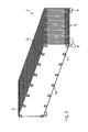
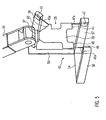
- the wafer boat 2 used in the apparatus 1 will be discussed with reference to Figures 2 and 3 , which show a perspective view and a schematic top view of the wafer boat 2, respectively.
- the wafer boat 2 is formed by a plurality of plates 6, a plurality of clamping or chucking and isolating units 7 and support feet 8.
- the shown wafer boat 2 is especially adapted for plasma treatment and specifically for plasma nitriding of wafers.
- Each of the plates 6 is formed of an electrically conductive material and especially the plates are formed as graphite plates.
- Each of the plates 6 has a parallel top edge 9 and a bottom edge 10, respectively.
- a plurality of V-formed grooves 12 is formed in the top edge 9, a plurality of V-formed grooves 12 is formed.
- each of the plates 6 has seven of these V-formed grooves 12.
- Each of the grooves 12 has a chamfer with respect to the upper surface, the chamfer generally being arranged at an angle of 45°, wherein also other angles may be provided.
- a total of twenty-three plates 6 are provided, the plates 6 being arranged substantially parallel to each other via corresponding clamping and isolating units 7, in order to form receiving or receptacle slits 15 therebetween. If twenty-three plates 6 are provided, twenty-two receptacle slots 15 are formed.
- the plates 6 comprise grooves of guiding elements (not shown) on a side facing an adjacent plate 6, the guiding elements having e.g. the form of three pins, which are provided for receiving wafers.
- a total of seven groups of guiding elements are arranged in the longitudinal direction of the plate elements, the guiding elements being provided for receiving a semiconductor wafer, as will be discussed in the following in more detail.
- the chuck and isolating units 7 generally consist of a bolt, spacers, and a nut each.
- the bolt and the spacers are made from an electrically isolating material.
- the nut may also be formed from an electrically isolating material, which is not necessary, however.
- the bolts as well as the spacers may be made e.g. from ceramic.
- Each of the spacers has preferably the same thickness, in order to arrange the plate elements parallel to each other.
- the bolt is sized in such a way that it may protrude through corresponding openings of the plates 6 as well as through corresponding spacers arranged between the plates 6.
- the plates 6 may be chucked or clamped via the nut.
- other chuck and isolating units are conceivable, which arrange the plates 6 generally parallel to each other in the above-mentioned manner.
- a total of sixteen of the chuck and isolating units 7 are provided, wherein eight units are provided adjacent to the top edge 9 of the plates 6 and wherein eight units are arranged adjacent to the bottom edge 10 of the plates 6.
- the chuck and isolating units 7 are equally distanced and divide the plates 6 into seven segments A-G in the longitudinal direction, each segment A-G corresponding to a group of guiding elements and grooves 12.
- the grooves 12 in the top edge 9 are located in an edge region of a corresponding segment A-G formed in this way.
- the segments A-G formed in this way are also aligned with groups of guiding elements on the corresponding plates 6.
- the twenty-two receptacle slots 15 between the twenty-three plates 6 as well as their segmentation into seven segments A-G along their longitudinal direction may best be seen in the top view according to Figure 3 .
- contact elements 20 at the wafer boat 2 may be perceived, the contact elements 20 being provided for electrically contacting the ends of the plates 6.
- the contact elements 20 are isolated with respect to each other, even though this is not shown in detail, and it is thus possible that adjacent plate elements are biased with inverse bias voltage, as is required for producing a plasma in the receptacle slots 15.
- the wafer transport robot 3 has a stationary pedestal or base 22, a drive unit 24, as well as a wafer gripper 26.
- the base 22 forms a firm base for the wafer transport robot 3 and especially for the drive unit 24.
- the drive unit 24 is formed by a plurality of arms 28 to 31 and a plurality of rotational joints 32 to 37, as is known in the art.
- One end of the drive unit 24 is connected to the base 22, while the other end supports the wafer gripper 26.
- a first rotational joint 32 of the drive unit 24 is connected to the base 22.
- the first rotational joint 32 is rotatable about a first axis perpendicular to the upper surface of the base 22.
- the first rotational joint 32 supports a second rotational joint 33 on the side not facing the base 22.
- the second rotational joint is rotatable about a second axis positioned perpendicular to the first axis.
- One end of a first arm 28 is connected to the second rotational joint 33.
- the first arm 28 may be arranged in an arbitrary rotational position and in an arbitrary angle with respect to the upper surface of the base via the first and second rotational joints 32, 33. The angle may be varied between 90° and about 0°.
- a third rotational joint 34 is provided at the other end of the first arm 28.
- the third rotational joint 34 is rotatable about a third axis, which is parallel to the second axis.
- the third rotational joint 34 is connected to one end of a second arm 29.
- the third rotational joint 34 supports the second arm in such a way that the angle between the first arm 28 and the second arm 29 may be adjusted.
- the other end of the second arm 29 is connected to a fourth rotational joint 35.
- the fourth rotational joint 35 is rotatable about a fourth axis which is perpendicular to the third axis and thus parallel to a longitudinal axis of the second arm 29.
- the fourth rotational joint 35 supports one end of a third arm 30. The rotational orientation of the third arm may be adjusted in relation to the second arm 29 via the fourth rotational joint 36.
- the other end of the third arm 30 supports a fifth rotational joint 36.
- the fifth rotational joint 36 is rotatable about a fifth axis which is arranged perpendicularly to the fourth axis.
- the fifth rotational joint 36 supports one end of a fourth arm 31 in such a way that the angle between the fourth arm 31 and the third arm 30 may be adjusted.
- the other end of the fourth arm supports a sixth rotational joint 37, which is rotatable about a sixth axis perpendicular to the fifth axis.
- the sixth rotational joint 37 supports the wafer gripper 26 on the side opposite the fourth arm 31.
- the sixth rotational joint 37 is able to adjust the rotational position of the wafer gripper 26 with respect to the fourth arm 31.
- Encoders are provided in the region of each rotational joint 32-37, the encoders being able to measure the rotational position of each rotational joint and to transmit the rotational position to a controller (not shown).
- the controller is adapted to control the movement of the rotational joints 32-37 in order to position the wafer gripper 26 in a desired position and orientation, as is known in the art.
- the controller usually starts from a coordinate system of the wafer transport robot 3, which has a fixed reference point (especially a point of origin) e.g. in the base 22. It is obvious that also another coordinate system may be the basis, the other coordinate system having a fixed reference system outside the base.
- Such wafer transport robots generally known per se, have an excellent repetition precision, but only have limited absolute precision as long as these wafer transport robots are not calibrated.
- the wafer gripper 26 is a gripper of the plate type having a support plate 38 and at least one vacuum suction device (not shown) for sucking a wafer to the support plate 38.
- the support plate 38 comprises a first edge region 39 adjacent to the connection to the sixth rotational joint 37.
- the support plate 38 comprises two spaced second edge regions 40 and 41, which are parallel to each other and are arranged in one plane at the end opposite to the sixth rotational joint 37. These edge regions may be formed by a straight bottom edge of the wafer gripper or by a contoured bottom edge, as is shown.
- the first edge region extends at an incline with respect to the second edge regions 40, 41, especially inclined at an angle of 45°, wherein also other angles may be provided. In any event, the inclination, i.e. the angle, is known.
- the wafer transport robot 3 described above is only an example, and it should be noted that also other wafer transport robots may be employed, which comprise e.g. a different drive unit for positioning a wafer gripper in a desired position and orientation.
- a drive unit which provides for positioning in two dimensions via rays, which are perpendicularly oriented with respect to each other (usually in a horizontal direction) and which provides for positioning in a third dimension (usually in a vertical direction) via a lifting device extending perpendicularly to the rays.
- a rotation tilt joint may be provided between the lifting device and the wafer gripper for orienting said wafer gripper in such a drive unit.
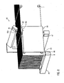
- FIG 4 shows a schematic perspective view of the measuring system 5 according to Figure 1 .
- the measuring system 5 is provided, on the one hand for measuring the spatial position of single plates 6 of the wafer boat 2, which was described above referring to Figures 2 and 3 and, on the other hand, for measuring the spatial position of a wafer gripper of the wafer transport robot 3, which will be explained in more detail in the following.
- the measuring system comprises a coordinate system having an origin or reference point in the area of a wafer boat.
- the measuring system 5 generally consists of a support element 42, a drive unit (not shown) therefore, as well as three sensors 45, 46, and 47, as well as an analyzing unit (not shown) for the sensor signals of the sensors.
- the drive unit for the support element 42 is a unit adapted for moving the support element 42 along a predetermined movement path. Alternatively, it is possible to provide a drive unit for the sensors 45, 46, and 47 in order to move these sensors along the support element 42.
- the support element 42 consists of a base element 50 as well as an auxiliary element 52.
- the base element 50 has a generally horizontal U-form, having a bottom wall 54 and two side legs 56, 57, extending perpendicular thereto.
- the side legs 56, 57 extend generally parallel with respect to each other.
- sensors 46, 47 are attached to the free ends, respectively.
- the auxiliary element 52 generally consists of a first L-shaped leg element 59 and a second leg element 60.
- the first leg element 59 is connected to the bottom wall 54 at one end in the area of the side leg 57 or may be formed in one piece therewith.
- the leg element 59 extends in a right angle with respect to the bottom wall 54 and the side leg 57 to the top.
- the leg element 59 is angled to an L-shape at the upper end.
- the second leg element 60 is connected to the first leg element 59 at this L-shaped angled region.
- the second leg element 60 extends perpendicularly to the first leg element 59 and thus generally parallel to the first and second side legs 56, 57.
- the second leg element 60 is connected to the first leg element 59 in such a way that an inclined wall surface for receiving the sensor 45 is formed. This inclined wall surface is angled by 45° with respect to the inner walls of the side legs 56, 57.
- leg element 56 is shown in Figure 4 as having a corresponding rotation
- the inclined wall surface may also be formed in another way, such as by machining a leg element 60, which is otherwise straightly orientated.
- the sensors 45, 46, and 47 are connected to the respective side legs 56, 57 and to the leg element 60 in such a way that they are generally located in one plane. However, the sensors may be mounted in such a way that they are not within one plane.
- the sensors 45, 46, 47 are laser distance sensors, which may measure a distance to an object in a corresponding measuring direction 45a, 46a, 47a, such as the distance to a corresponding edge region 39-41 of the holding plate or to a side edge 9 or 10 of a plate 6 of the wafer boat 2.
- Such sensors detect laser beams reflected from the respective object in a known way, wherein the sensors are preferably perpendicularly directed to the corresponding surface of the object.
- the sensors 46, 47 are laterally spaced by a distance corresponding approximately to the width of the corresponding segments of the wafer boat 2 according to Figures 2 and 3 (or corresponding to a width of the bottom edge of the holding plate 38 of the wafer gripper 26).
- the sensor 45 is inclined according to the inclination of the groove 12 (or according to the inclination of the edge region 39 to the edge regions 41, 42).
- Figure 5 shows a schematic perspective view of the measuring system 5 when measuring the spatial position of a wafer gripper 26 of the wafer transport robot.
- a measurement is carried out e.g. during a calibration routine which may be carried out one time prior to a start-up procedure of the wafer transport robot, in order to increase the absolute precision of the wafer transport robot.
- the calibrating routine may be repeated periodically or after certain events, such as after changing the wafer transport robot, after changing certain components of the wafer transport robot, or after an inadvertent collision, wherein a part of the wafer transport robot collides with an external object.
- An example of such a calibrating routine is explained in the following.
- the wafer transport robot 3 is controlled via the control unit in such a way that the control unit moves the wafer gripper 26 to a first position, which corresponds approximately to a theoretical loading position of the wafer boat 2, wherein no wafer boat 2 is present in a loading position at this point in time.
- the control unit or controller specifies a coordinate position stored as a theoretical loading position in the coordinate system of the wafer transport robot, wherein the wafer gripper 26 is to be moved to this coordinate position (usually a center point of the wafer gripper is moved to the position).
- a theoretical loading position may be e.g. a position in which a perfectly positioned ideal wafer boat 2 would receive a wafer.
- the wafer transport robot 3 Since the wafer transport robot 3 is not yet calibrated at this point in time, the wafer transport robot would usually not be able to move the wafer gripper to the exact theoretical loading position (which is a desired position). In this position, the encoder values of the individual rotational joints 32-37 will be sampled and the spatial position of the wafer gripper 26 will be determined automatically by the measuring system 5, as is indicated in Figure 5 .
- the wafer gripper 26 In the first position, the wafer gripper 26 is oriented within the limits of its absolute positioning precision in such a way, with respect to the measuring system 5, that the plane of the holding plate 38 of the wafer gripper 26 is generally perpendicular to the direction of movement of the supporting element 42. Furthermore, the first sensor 45 is oriented generally perpendicular to the edge region 39 of the holding plate 38, while the second and third sensors 46, 47 are oriented generally perpendicular to one of the edge regions 40, 41, at a bottom edge of the holding plate 38 of the wafer gripper 26. During the measuring of the wafer gripper 26, the sensors 45, 46, 47 are moved generally perpendicular to the plane of the holding plate 38 and beyond the holding plate 38 via the drive unit (not shown in detail) for the support element 42.
- the movement of the drive unit and thus the position of the respective sensors 45, 46, and 47 in the direction of movement is determined via one or more encoders.
- output signals depending on the encoder values of the sensors 45, 46, and 47 are produced.
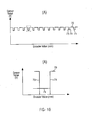
- Figure 10A shows an example of an output signal of a sensor depending on an encoder value, wherein the output signal according to Figure 10A has been generated during movement of the sensor across several plates 6 of a wafer boat 2. Such a signal is produced e.g. during determination of the spatial position of the plates 6 of the wafer boat 2, as is explained in more detail in the following.
- Figure 10B shows an enlarged sub-area of the sensor signal during movement of the sensors across a single plate 6.
- Such an output signal, according to Figure 10B would also result from measuring the wafer gripper 26, since only one single plate, i.e. the holding plate 38, would be detected in this case.
- the output signals of the sensors 45, 46, and 47 are located on the first (upper) level 70, if no plate is in the field of view of the respective sensor, and the signals are located on the second (lower) level 71, if a plate, such as a plate 6 of the wafer boat 2 or the holding plate 38 of the wafer gripper 26, is located in the field of view of the sensor.
- the transitions between the first and the second level are formed by the corresponding edges 73, 74 of the sensor signal, wherein the respective edge 73 indicates the entry of the plate 6/holding plate 38 into the field of view of a sensor, when transitioning from the first level 70 to the second level 71, and wherein the edge 74, when transitioning from the second level 71 to the first level 70, indicates exiting of the plate 6/holding plate 38 from the field of view of the sensor.
- each of the levels 70, 71 and the edges 73, 74 is illustrated in such a way that a perfect rectangular graph is formed, the person skilled in the art will appreciate that the signals will not be as straight as shown in reality. However, mean levels for each of the levels for determining a distance may be calculated.
- the edge recognition may be achieved e.g. via determining a threshold value.
- the distance between the corresponding edge of the plate 6/holding plate 38 and the sensor may be determined.
- the position of the edges along the direction of movement of the sensors may be determined.
- the spatial position of the plates 6/holding plate 38 may be clearly determined. Especially, the spatial position with respect to the theoretical loading position as a desired position may be determined.
- At least one adjustment or compensation parameter may be determined for controlling at least one of the rotational joints 32-37 of the wafer transport robot, such that the wafer transport robot positions the wafer gripper closer to the desired position when moving again to the theoretical loading position.
- the process mentioned above may be repeated one time or several times for the first position, wherein moving the wafer gripper 26 to the first position is carried out, taking into account the at least one compensation parameter during each further pass.
- the process may be repeated for the first position as long as the wafer transport robot positions the wafer gripper in the desired position within certain tolerances. In this way, the wafer transport robot automatically learns the theoretical loading position.
- each position corresponds to a respective theoretical loading position.
- each of the theoretical loading positions of an ideal wafer boat 2, which is placed in the ideal position i.e. a wafer boat having perfectly parallel, perfectly spaced, and non-distorted plates 6
- the previously determined compensation parameters may be taken into account already for the first position, such that the required iteration cycles for reaching a positioning within predetermined tolerances are reduced with progressing calibration.
- the wafer transport robot thus calibrated may be employed for loading/unloading operations of real wafer boats. Since the wafer boats are usually not perfectly positioned and are usually not of the ideal type, the wafer transport robot must move the wafer gripper to loading positions not corresponding to the measured positions. These positions will be approached via interpolation or via other processes based on the actually measured positions and taking into account the compensation parameters determined during measuring.
- the measuring system 5 is able to measure the wafer gripper 26 during calibrating of the wafer transport robot 3. During the measuring process, the measuring system directly measured the wafer gripper 26. In order to facilitate direct measuring, the holding plate 38 must have a certain form, which is shown e.g. in Figure 5 . However, the measuring system may also determine the spatial position of the wafer gripper indirectly via a plate element fixed to the wafer gripper in known manner, as will be explained in more detail in the following referring to Figure 6 .
- FIG. 6 shows a schematic perspective view of the measuring system 5 when determining the spatial position of an alternative wafer gripper 26.
- the wafer transport robot and the measuring system are constructed in the same way as described above. Only the wafer gripper 26 is different from the wafer gripper described above. Also in this embodiment, the wafer gripper 26 has a holding plate 38 having an integrated vacuum gripper (not shown) for sucking a wafer to the holding plate 38.
- the holding plate has a generally rectangular form and has dimensions which are smaller than those in the embodiment described above.
- the holding plate 38 receives a plate element 76 in a known, defined position for calibrating the wafer transport robot 3, the plate element 76 having known dimensions. Receiving the plate element in a known, defined position may be ensured via e.g. alignment contours (not shown) on the wafer gripper 26 and/or on the plate element 76.
- the plate element 76 has a straight top edge 77 as well as a straight bottom edge 78, extending parallel to the top edge.
- a groove 79 having a known chamfer or inclination is formed in the top edge.
- the dimensions of the plate element 76 are designed in such a way that the sensors 45, 46, and 47 may each detect a different edge region of the plate element 76 during one single movement of each sensor.
- the sensor 45 should be able to detect an edge region in the groove 79, while the sensors 46 and 47 are able to detect spaced edge regions of the bottom edge 78.
- the plate element 76 has the dimensions and the form of a segment of a plate 6 of the wafer boat 2.
- the plate element 76 has a known form and may be received in known, defined manner in the wafer gripper 26, it is possible to determine the spatial position of the wafer gripper 26 via corresponding measurement of the plate element 76 during calibration of the wafer transport robot. To this end, e.g. the same calibration routine as mentioned above may be used.
- the wafer transport robot 3 is controlled by the controller unit in such a way that the wafer transport robot 3 moves a predetermined point of the wafer gripper (e.g. the central point thereof) to a first position, which is located within a theoretical loading zone of the wafer boat 2, wherein no wafer boat 2 is present in the loading zone at this point in time.
- the controller specifies a corresponding coordinate position in the coordinate system of the wafer transport robot 3.
- a region or space in which, when taken into account imprecise positioning of a wafer boat 2, it may be expected that a loading operation may take place, is regarded as a theoretical loading zone. While defined theoretical loading positions had been approached during a fast calibration routine, an arbitrary position within the theoretical loading zone will be approached during the alternative calibration routine.
- the encoder values of the corresponding rotational joints 32-37 may be detected in this position and may be stored. Afterwards, the spatial location of the wafer gripper 26 is automatically determined in this position by use of the measuring system 5. Especially, the sensors 45, 46, and 47 will be moved along the predetermined movement paths across the plate element 76 on the wafer gripper 26. During this movement, the sensors detect the corresponding edge regions of the plate element. Particularly, the sensor 45 detects or scans an edge region of the groove 79, while the sensors 46 and 47 detect or scan adjacent edge regions at the bottom edge 78. Thus, the spatial position of the wafer gripper 26 may be determined and may be related to the coordinate approached and/or to the encoder values.
- the wafer gripper may be positioned in the first position in different orientations while maintaining the predetermined point of the wafer gripper. This may be achieved by rotating the wafer gripper about different axes extending through the first position. This is done by correspondingly controlling the rotational joints by use of the robot coordinate system. In the different orientations, the corresponding spatial position of the wafer gripper 26 is automatically determined in the way described above. This process is repeated for a plurality of other positions within the theoretical loading zone. Such different positions are indicated by dots in Figure 6 . Each of the approached coordinates and/or each of the encoder values and the correspondingly determined spatial position of the wafer gripper are stored.
- control data of the wafer transport robot 3 (coordinates/encoder values) are associated with the correspondingly determined spatial positions of the wafer gripper.
- the wafer transport robot 3 may derive corresponding control data of the wafer transport robot for moving the wafer gripper 26 to a desired loading/unloading position. This may be achieved e.g. by interpolating data between the measured positions, as may be obvious for the person skilled in the art.
- the spatial position of the wafer gripper is determined.
- the absolute spatial position is determined but only the position with respect to the measuring system.
- the absolute spatial position may be derived therefrom, however this is not necessary, as will be explained in the following.
- the spatial position of the plates 6 and thus of the receptacles for wafers located thereon is determined in advance by the measuring system 5. From this spatial position, a corresponding loading position may be determined, which needs to be approached by the wafer gripper 26 of the wafer transport robot 3. Since the same measuring system 5 is used for determining the spatial position of the plates 6 as is used for calibrating the wafer transport robot 3, the same reference coordinates (i.e. of the measuring system) are used, and the spatial position of a measured object does not need to be determined absolutely but only with respect to the measuring system.
- Figure 7 shows a schematic perspective view of the measuring system 5 while measuring the wafer boat 2, which is located in a loading/unloading position.
- Figure 7 shows the measuring system in a position, in which a first plate 7 located on the outer surface of the wafer boat 2 is measured in the region of a segment thereof, located on the outer side.
- the wafer boat 2 is aligned with respect to the measuring system 5 in such a way that the first sensor 45 is directed generally perpendicular to a chamfer or to the inclined part of the groove 12, while the second and third sensors 46, 47 are directed generally perpendicular to a bottom edge of the plates 6.
- the sensors 45, 46, 47 are moved generally perpendicular to the plane of the plates 6 across the plates 6 via the drive unit (not shown in detail) for the support element 42. Movement of the drive unit and thus the position of the corresponding sensors in the direction of movement is determined via one single encoder or a plurality of encoders. During movement of the sensors, output signals of the sensors depending on the encoder value may be yielded, as is illustrated e.g. in figure 10.
- Figure 10A shows an example of an output signal of a distance sensor as a function of an encoder value during movement of the sensor across several plates 6.
- Figure 10B shows an enlarged sub-area of the sensor signal during movement of the sensor across a plate 6.
- the spatial position of the plates 6 may be determined at least in the region of the correspondingly measured segments A-G. Especially, also the spatial position with respect to a desired position (i.e. a perfectly aligned position from which the theoretical loading positions of the calibrating process described above may be derived) may be determined. Thereafter, this position information will be transmitted to the control unit, wherein the control unit controls the wafer transport robot 3, which had been calibrated as described above, in order to carry out a loading/unloading operation.
- a desired position i.e. a perfectly aligned position from which the theoretical loading positions of the calibrating process described above may be derived
- Figure 8 shows a schematic perspective view of an alternative measuring system 5 for determining the spatial position of the plates 6 of a wafer boat 2.
- the same reference signs as were used above will be used in Figure 8 , as far as the same or similar features are described.
- the measuring system 5 has the same construction as was described above. However, the measuring system also comprises an additional element having the form of a reference plate 80, which is maintained in a predetermined position by a device not shown in detail.
- the reference plate 80 has a top edge 82 as well as a bottom edge 83 extending parallel to the top edge.
- the reference plate 80 has a width and a height corresponding to the width and the height of a segment of one plate 6. Of course, it is also possible to form a longer reference plate 80, e.g. corresponding to the length of a whole plate 6.
- a groove 85, corresponding to the groove 12 in the top edge 9 of the plate 6, is formed in the top edge 82.
- the reference plate 80 is positioned in a predefined position, it is possible to first measure the reference plate 80 prior to measuring the plates 6 of a wafer boat 2, and thereafter measure the corresponding segments of the plates 6. By this means, the relative position of the individual plates 6 with respect to the reference plate 80 may be determined. By measuring the reference plate 80, also the position of the support 42 as well as the position of the individual sensors 45-47 may be calibrated. It is also possible to determine the precise spatial position of the wafer boat on a carriage supporting or transporting the wafer boat 2 by use of such a reference plate 80. However, particularly e.g. temperature drifts of the sensors 45-47 may be compensated during such a calibration. Of course, the reference plate 80 may also be measured in the same way prior to a corresponding measuring of the wafer gripper 26 when carrying out a calibration of the wafer transport robot 3.
- FIG. 9A-9C Figures 9A-9C and Figures 11A and 11B will be referred to, these figures showing, on the one hand, schematic front views of the measuring system 5 for measuring different segments A-G of a wafer boat 2 and, on the other hand, a schematic front view of the measuring system while determining the spatial position of a laterally displaced plate segment of a wafer boat as well as an enlarged detailed view of a sensor signal of a sensor.
- a segment A-G of the plates 6 to be measured is aligned with the support element 42.
- the alignment is carried out in such a way that the sensor 45 moves across the top edge 9 in the region of the groove 12 during movement of the support element, perpendicularly to the plane of the plates 6.
- the sensors 46, 47 move across the bottom edge 10 of the plates in the region of a segment A-G to be measured during a corresponding movement.
- the sensor element 45 is located above and laterally with respect to the segment A-G to be measured while measuring a respective segment A-G.
- the wafer robot 3 has access to a corresponding receptacle slot 15 from above, directly during measuring of the corresponding plates 6, in order to insert a wafer into the group of guiding elements of the plate 6 being measured or in order to remove a wafer therefrom.
- the loading and unloading operations are carried out directly following the measuring of the plates 6, since the risk of position variations in the meantime may be reduced substantially in doing so.
- FIG. 11A shows a segment of a plate 6 which is shifted sideways with respect to a desired position but is otherwise precisely positioned. In this figure, the desired position is schematically shown in a dashed outline.
- the sensor signals of the sensors 46, 47 will correspond to the desired sensor signal if the wafer boat is laterally shifted in such a way but is otherwise precisely positioned. Particularly, the edges 73, 74 will occur corresponding to expected encoder values, and the second level 71 will be an expected level.
- the sensor signal of the sensor 45 will differ from an expected sensor signal. While the edges 73, 74 will appear at the expected point in time, i.e. will occur with respect to the expected encoder values, the second level will be on a different height, since the sensor 45 measures the distance to a different position of the groove 12 instead of the distance to the expected position. By this means, a different distance to the edge of the groove 12 will be determined, which is shown as a different height of the second level 71. This is shown in Figure 11B , wherein the dashed line of the level 71 indicates the expected height, while the solid line indicates the actual level 71.
- a distance variation may be measured, and based on the distance measurement, the lateral shift of the wafer boat 2 may be determined based on the known geometry.
- the position, determined in such a way will be transferred to the wafer transport robot 3 thereafter, wherein the wafer transport robot 3 is able to control the wafer gripper 26 so as to load/unload the receiving slots 15.
- loading and/or unloading of a receiving slot 15 adjacent to a plate 6 may be carried out directly after the determination of the position.
- loading and/or unloading of the receiving slots 15 may be carried out directly following the corresponding determination of the position of the plates 6, which form the receiving slot 15 in between.
- Figure 11 shows only one example, wherein the spatial position of the plates 6 may be determined with respect to an expected, desired position.
- a lateral shift of the wafer boat 2, i.e. a shift perpendicular to the plates 6, may be determined e.g. based on the position of the corresponding edges 73, 74 of the sensor signals of the sensors 45, 46, and 47.
- a vertical shift of the wafer boat 2 may be determined from distance information, i.e. the height of the second level 71 of the corresponding sensor signals of the sensors 45, 46, and 47.
- Vertical shifts on one side may also be determined based on distance information of the sensor signals of the sensors 45, 46, and 47.
- Diagonal shifts i.e. lateral to a longitudinal central plane of the wafer boat 2 may be determined based on the edges 73, 74 of the corresponding sensor signal from at least two laterally distance sensors, i.e. the sensors 45 and 46 or the sensors 46 and 47. Of course, also the edge information of all sensors may be used.
- a lateral tilt of the wafer boat 2 i.e. a tilt across the width of the wafer boat 2 may be determined e.g. based on the edge information of the corresponding sensors, since the edge information of the upper sensor 45 would indicate a shift to a first direction, while the edge information of the sensors 46 and 47 would show a lateral shift to the other direction.
- edge information of the sensors 46 and 47 would show a lateral shift to the other direction.
- more complex and super-imposed shifts may be determined.
- the reference plate may be employed for calibrating the measuring device prior to a corresponding series of measurements.
- the number of plates of the wafer boat and the subdivision in different segments may vary from the shown form. It is also possible to mount the sensors e.g. to a respective individual support element, the support element being movable along a predetermined movement path via corresponding drive units. Also, the wafer transport robot 3 may be constructed differently from the shown wafer transport robot.
- the wafer transport robot needs to be a type which is adapted to pick up a wafer at a first position and to transport the wafer from the first position to a second position.
Landscapes
- Engineering & Computer Science (AREA)
- Robotics (AREA)
- Mechanical Engineering (AREA)
- Container, Conveyance, Adherence, Positioning, Of Wafer (AREA)
Claims (14)
- Verfahren zum Kalibrieren eines Wafertransportroboters (3) zum Beladen eines Waferbootes (2) mit Wafern, wobei das Waferboot (2) eine Vielzahl von Platten (6) aufweist, die im Wesentlichen parallel zueinander, einander gegenüberliegend, angeordnet sind, und wobei das Waferboot (2) zwischen benachbart zueinander angeordneten Platten (6) eine Vielzahl von Aufnahmen zum Aufnehmen der Wafer aufweist, und wobei der Wafertransportroboter (3) einen Wafergreifer (26) aufweist, der geeignet ist, einen Wafer in die Aufnahmen (15) zwischen den Platten (6) einzusetzen und hieraus zu entnehmen,
wobei das Verfahren gekennzeichnet ist durch:a.) Bewegen des Wafergreifers (26) in eine erste Position, die annähernd einer theoretischen Beladeposition des Waferbootes (2) entspricht;b.) automatisches Bestimmen der räumlichen Lage des Wafergreifers (26) durch
Bewegen von wenigstens drei Sensoren (45, 46, 47) entlang vorbestimmter Bewegungspfade über den Wafergreifer (26) wobei die Sensoren (45, 46, 47) bei der Bewegung jeweils auf einen Kantenbereich (39, 40, 41) des Wafergreifers oder auf einen Kantenbereich (77, 78, 79) eines Plattenelements (76), das in einer bekannten Weise durch den Wafergreifer (26) getragen wird, gerichtet werden,
Bestimmen der Positionen der Sensoren (45, 46, 47) entlang ihrer jeweiligen Bewegungspfade und Erfassen der Positionen in welchen ein jeweiliger Kantenbereich (39, 40, 41; 77, 78, 79) in den Messbereich jeweils eines der Sensoren (45, 46, 47) gelangt und aus diesem austritt, und
Messen eines Abstands zwischen einem jeweiligen Sensor (45, 46, 47) und dem jeweiligen Kantenbereich (39, 40, 41; 77, 78, 79);c.) Bestimmen wenigstens eines Korrekturparameters zum Positionieren des Wafergreifers (26) anhand einer Differenz zwischen der ermittelten räumlichen Lage des Wafergreifers (26) und der theoretischen Beladeposition;d.) optionales Wiederholen der Schritte a.) bis c.) für weitere theoretische Beladepositionen. - Verfahren nach Anspruch 1, dadurch gekennzeichnet, dass der Wafergreifer (26) nach dem Ermitteln des wenigstens einen Korrekturparameters jeweils unter Berücksichtigung des wenigstens einen Korrekturparameters in eine neue Position bewegt wird, die annähernd der theoretischen Beladeposition des Waferbootes (2) entspricht und die räumlichen Lage des Wafergreifers (26) gemäß Schritt b.) neu bestimmt und wenigstens ein neuer Korrekturparameter gemäß Schritt c.) ermittelt wird, wobei dieser Vorgang wiederholt wird, falls die Differenz zwischen ermittelter räumlicher Lage des Wafergreifers (26) und theoretischer Beladeposition außerhalb vorbestimmter Toleranzen liegt.
- Verfahren zum Kalibrieren eines Wafertransportroboters (3) zum Beladen eines Waferbootes (2) mit Wafern, wobei das Waferboot (2) eine Vielzahl von Platten (6) aufweist, die im Wesentlichen parallel zueinander, einander gegenüberliegend, angeordnet sind, und wobei das Waferboot (2) zwischen benachbart zueinander angeordneten Platten (6) eine Vielzahl von Aufnahmen zum Aufnehmen der Wafer aufweist, und wobei der Wafertransportroboter (3) eine Vielzahl von Gelenken (32 bis 37) und einen Wafergreifer (26) aufweist, der geeignet ist, einen Wafer in die Aufnahmen (15) zwischen den Platten (6) einzusetzen und hieraus zu entnehmen,
wobei das Verfahren gekennzeichnet ist durch:a.) Bewegen eines vorbestimmten Punktes des Wafergreifers (26) an eine erste Position innerhalb einer theoretischen Beladezone für ein Waferboot (2) unter Verwendung eines Roboterkoordinatensystems;b.) automatisches Bestimmen der räumlichen Lage des Wafergreifers (22) durch
Bewegen von wenigstens drei Sensoren (45, 46, 47) entlang vorbestimmter Bewegungspfade über den Wafergreifer (26) wobei die Sensoren (45, 46, 47) bei der Bewegung jeweils auf einen Kantenbereich (39, 40, 41) des Wafergreifers oder auf einen Kantenbereich (77, 78, 79) eines Plattenelements (76), das in einer bekannten Weise durch den Wafergreifer (26) getragen wird, gerichtet werden,
Bestimmen der Positionen der Sensoren (45, 46, 47) entlang ihrer jeweiligen Bewegungspfade und Erfassen der Positionen in welchen ein jeweiliger Kantenbereich (39, 40, 41; 77, 78, 79) in den Messbereich jeweils eines der Sensoren (45, 46, 47) gelangt und aus diesem austritt, und
Messen eines Abstands zwischen einem jeweiligen Sensor (45, 46, 47) und dem jeweiligen Kantenbereich (39, 40, 41; 77, 78, 79);c.) Bewegen des Wafergreifers (26) in unterschiedliche Ausrichtungen unter Verwendung des Roboterkoordinatensystems, wobei der vorbestimmte Punkt des Wafergreifers (26) jeweils in der ersten Position beibehalten wird, und
automatisches Bestimmen der jeweiligen räumlichen Lage des Wafergreifers (26) in den unterschiedlichen Ausrichtungen gemäß Schritt b.);d.) Bewegen des vorbestimmten Punktes des Wafergreifers (26) an eine weitere Position innerhalb des theoretischen Beladebereichs des Waferbootes (2) unter Verwendung des Roboterkoordinatensystems und Wiederholen der Schritte b.) und c.) in den jeweiligen Positionen; unde.) Speichern der Koordinatendaten des Roboterkoordinatensystems entsprechend den jeweils Punkten zu denen der Wafergreifer (26) bewegt wurde und den entsprechenden räumlichen Lagen des Wafergreifers (26). - Verfahren zum Be- und/oder Entladen eines Waferbootes (26) mit einem Wafertransportroboter (3), wobei das Waferboot (2) eine Vielzahl von Platten (6) aufweist, die im Wesentlichen parallel zueinander, einander gegenüberliegend, angeordnet sind, und wobei das Waferboot (2) zwischen benachbart zueinander angeordneten Platten (6) eine Vielzahl von Aufnahmen zum Aufnehmen der Wafer aufweist, dadurch gekennzeichnet, dass der Wafertransportroboter nach einem der Ansprüche 1 bis 3 kalibriert ist,
wobei für einen jeweiligen Be- oder Entladevorgang die räumliche Lage der Platten (6) unter Verwendung der wenigstens drei Sensoren (45, 46, 47), die für die Kalibrierung des Wafertransportroboters (3) verwendet wurden, bestimmt wird,
die jeweils ermittelte räumliche Lage der Platten (6) an den Wafertransportroboter (3) übermittelt wird, und
der Wafertransportroboter (3) seinen Wafergreifer (26) entsprechend der Lageinformation steuert, um das Waferboot (2) zu be- und/oder entladen. - Verfahren nach Anspruch 4, dadurch gekennzeichnet, dass die räumliche Lage der Platten (6) durch die folgenden Schritte bestimmt wird:Bewegen der wenigstens drei Sensoren (45, 46, 47) entlang der vorbestimmten Bewegungspfade, wobei wenigstens ein erster Bewegungspfad oberhalb des Waferbootes (2), wenigstens ein zweiter Bewegungspfad unterhalb des Waferbootes (2) und ein dritter Bewegungspfad seitlich beabstandet zu dem ersten oder zweiten Bewegungspfad ober- oder unterhalb des Waferbootes (2) liegt, und wobei die Sensoren (45, 46, 47) bei der Bewegung jeweils auf einen Kantenbereich (9, 10, 12) der Platten (6) gerichtet werden;kontinuierliches Bestimmen der Position der Sensoren (45, 46, 47) entlang des jeweiligen Bewegungspfads und Erfassen der Position in welcher ein jeweiliger Kantenbereich (9, 10, 12) der Platten (6) in den Messbereich eines der Sensoren (45, 46, 47) gelangt und aus diesem austritt; undMessen des Abstands zwischen einem jeweiligen Sensor (45, 46, 47) und dem jeweiligen Kantenbereich (9, 10, 12) der Platten (6).
- Verfahren zum Kalibrieren eines Wafertransportroboters oder Verfahren zum Be- und/oder Entladen eines Waferbootes nach einem der vorhergehenden Ansprüche, dadurch gekennzeichnet, dass die Sensoren (45, 46, 47) für eine Kalibrierung der Sensoren (45, 46, 47) zunächst entlang der vorbestimmten Bewegungspfade über wenigstens eine Referenzplatte (80) bewegt werden,
wobei während der Bewegung erfasst wird, in welcher Position die Sensoren (45, 46, 47) entlang des jeweiligen Bewegungspfads den Eintritt und den Austritt jeweiliger Referenzkanten (82, 83, 85) der wenigstens einen Referenzplatte (80) in den Messbereich der Sensoren (45, 46, 47) detektieren und wobei der Abstand zwischen jedem Sensor (45, 46, 47) und der jeweiligen Referenzkanten (82, 83, 85) der Referenzplatte (80) gemessen wird. - Verfahren zum Kalibrieren eines Wafertransportroboters oder Verfahren zum Be- und/oder Entladen eines Waferbootes nach einem der vorhergehenden Ansprüche, dadurch gekennzeichnet, dass wenigstens zwei der Sensoren (46, 47) bei der Bewegung jeweils parallel zueinander angeordnete Kantenbereiche und/oder Referenzkantenbereiche erfassen und wenigstens ein Sensor (45) einen schrägen Kantenbereich und/oder Referenzkantenbereich, der eine bekannte Schräge bezüglich der Kantenbereiche und/oder Referenzkantenbereiche besitzt, erfassen.
- Verfahren zum Kalibrieren eines Wafertransportroboters oder Verfahren zum Be- und/oder Entladen eines Waferbootes nach einem der vorhergehenden Ansprüche, dadurch gekennzeichnet, dass die Sensoren (45, 46, 47) über einen gemeinsamen Bewegungsmechanismus bewegt werden.
- Vorrichtung (1) zum Be- und /oder Entladen eines Waferbootes (2), das eine Vielzahl von Platten (6) aufweist, die im Wesentlichen parallel zueinander, einander gegenüberliegend angeordnet sind und zwischen benachbarten Platten (6) Aufnahmeschlitze (15) zur Aufnahme von Wafern bilden, wobei die Vorrichtung (1) folgendes aufweist:einen Wafertransportroboter (3) mit einem Wafergreifer (26) und einer Vielzahl von Armen (28 bis 31) und Drehgelenken (32 bis 37) zum Positionieren des Wafergreifers (26);eine Sensoranordnung mit wenigstens drei Sensoren (45, 46, 47), wobei jeder der Sensoren (45, 46, 47) geeignet ist entlang einer Messrichtung einen Abstand zwischen dem Sensor (45, 46, 47) und einem Kantenbereich (9, 10, 12; 39, 40, 41; 77, 78, 79; 9, 10, 12; 82, 83, 85) eines in den Messbereich des Sensors (45, 46, 47) gelangenden Elements (38; 76; 6; 80) zu messen;wenigstens eine Trag- und Bewegungseinheit (42) zum Tragen und Bewegen der Sensoren (45, 46, 47) entlang vorbestimmter, bekannter Bewegungspfade;wenigstens eine Einheit zum Bestimmen der Position der Sensoren (45, 46, 47) entlang der jeweiligen Bewegungspfade; undwenigstens eine Steuervorrichtung zum Steuern der Bewegung des Wafertransportroboters (3) und der Sensoranordnung, wobei die Steuervorrichtung konfiguriert ist, die Sensoranordnung im Rahmen einer Kalibrierung nach einem der Ansprüche 1 bis 2 oder 3 so zu steuern,dass sie die räumliche Lage des Wafergreifers (26) innerhalb einer Be- und/oder Entladezone des Waferbootes (2) ermitteln kann, und die Bewegung des Wafertransportroboters (3) bei einer Be- und/oder Entladung aufgrund der ermittelten räumlichen Lage zu steuern.
- Vorrichtung nach Anspruch 9, dadurch gekennzeichnet, dass der Wafergreifer (26) ein plattenförmiger Wafergreifer ist.
- Vorrichtung nach Anspruch 9 oder 10, dadurch gekennzeichnet, dass die Steuervorrichtung geeignet ist,
einerseits die Sensoranordnung so zu steuern, dass sie vor einem jeweiligen Be- und/oder Entladungsvorgang die räumliche Lage einer Platte (6) des Waferbootes (2) ermittelt, und
andererseits die Bewegung des Wafertransportroboters (3) anhand der ermittelten räumlichen Lage des Waferbootes (2) zu steuern. - Vorrichtung nach einem der Ansprüche 9 bis 11, gekennzeichnet durch eine Referenzplatte (80), die benachbart zu einem Be- und/oder Entladebereich für das Waferboot (2) angeordnet ist und sich im wesentlichen senkrecht zu den vorbestimmten Bewegungspfaden erstreckt, wobei die Steuervorrichtung geeignet ist, die Sensoranordnung vor der Bestimmung der räumlichen Lage des Wafergreifers (26) und/oder der wenigstens einen Platte (6) des Waferbootes (2) an der Referenzplatte (80) vorbeizubewegen, um eine Referenzmessung für die Sensoren (45, 46, 47) der Sensoranordnung zu ermöglichen.
- Vorrichtung nach einem der Ansprüche 9 bis 12, dadurch gekennzeichnet, dass während der Bewegung entlang des vorbestimmten Bewegungspfades wenigstens zwei der Sensoren (46, 47) auf jeweilige Kantenbereich des zu detektierenden Elements gerichtet sind, die parallel zueinander sind, und dass wenigstens ein Sensor (45) auf einen schrägen Kantenbereich des zu detektierenden Elements gerichtet ist, wobei der schräge Kantenbereich eine bekannte Schräge bezüglich der parallelen Kantenbereiche besitzt.
- Vorrichtung nach einem der vorhergehenden Ansprüche, dadurch gekennzeichnet, dass die Bewegungspfade des Sensors (45, 46, 47) im Wesentlichen senkrecht zu einem zu detektierenden Element angeordnet sind.
Applications Claiming Priority (2)
| Application Number | Priority Date | Filing Date | Title |
|---|---|---|---|
| DE102010025483A DE102010025483A1 (de) | 2010-06-29 | 2010-06-29 | Verfahren und Vorrichtung zum Kalibrieren eines Wafertransportroboters |
| PCT/EP2011/003202 WO2012000663A1 (en) | 2010-06-29 | 2011-06-29 | Method and apparatus for calibrating a wafer transport robot |
Publications (2)
| Publication Number | Publication Date |
|---|---|
| EP2589073A1 EP2589073A1 (de) | 2013-05-08 |
| EP2589073B1 true EP2589073B1 (de) | 2015-09-23 |
Family
ID=44510849
Family Applications (1)
| Application Number | Title | Priority Date | Filing Date |
|---|---|---|---|
| EP11743023.1A Not-in-force EP2589073B1 (de) | 2010-06-29 | 2011-06-29 | Verfahren und vorrichtung zur kalibrierung eines wafertransportroboters |
Country Status (4)
| Country | Link |
|---|---|
| EP (1) | EP2589073B1 (de) |
| JP (1) | JP5943914B2 (de) |
| DE (1) | DE102010025483A1 (de) |
| WO (1) | WO2012000663A1 (de) |
Cited By (1)
| Publication number | Priority date | Publication date | Assignee | Title |
|---|---|---|---|---|
| EP4533029A4 (de) * | 2022-05-26 | 2026-01-21 | Abb Schweiz Ag | Verfahren und vorrichtung zur kalibrierung der thermischen drift eines roboters |
Families Citing this family (22)
| Publication number | Priority date | Publication date | Assignee | Title |
|---|---|---|---|---|
| DE102010026610A1 (de) | 2010-07-09 | 2012-01-12 | Centrotherm Thermal Solutions Gmbh + Co. Kg | Unterdruck-Saugeinheit und Greifer |
| DE102011109444A1 (de) | 2011-08-04 | 2013-02-07 | Centrotherm Photovoltaics Ag | Abstandselement für Platten eines Waferbootes |
| DE202012102503U1 (de) | 2012-07-06 | 2012-08-03 | Rena Gmbh | Vorrichtung zum mehrspurigen Transport von flachen Gegenständen |
| WO2014109027A1 (ja) * | 2013-01-10 | 2014-07-17 | 株式会社島津製作所 | 基板移載システム及び基板移載方法 |
| US10297481B2 (en) | 2013-03-21 | 2019-05-21 | Tokyo Electron Limited | Magnetic annealing apparatus |
| US9508914B2 (en) | 2013-03-21 | 2016-11-29 | Tokyo Electron Limited | Magnetic annealing apparatus |
| JP6134174B2 (ja) * | 2013-03-21 | 2017-05-24 | 東京エレクトロン株式会社 | 磁気アニール装置 |
| JP6134172B2 (ja) * | 2013-03-21 | 2017-05-24 | 東京エレクトロン株式会社 | 磁気アニール装置 |
| DE102015004430B4 (de) | 2015-04-02 | 2017-01-05 | Centrotherm Photovoltaics Ag | Vorrichtung und Verfahren zur Plasmabehandlung von Wafern |
| DE102015004419A1 (de) | 2015-04-02 | 2016-10-06 | Centrotherm Photovoltaics Ag | Waferboot und Plasma-Behandlungsvorrichtung für Wafer |
| DE102015004414A1 (de) | 2015-04-02 | 2016-10-06 | Centrotherm Photovoltaics Ag | Plasma-Behandlungsvorrichtung für Wafer |
| DE102015004352A1 (de) | 2015-04-02 | 2016-10-06 | Centrotherm Photovoltaics Ag | Waferboot und Behandlungsvorrichtung für Wafer |
| DE102015014903A1 (de) * | 2015-11-18 | 2017-05-18 | Centrotherm Photovoltaics Ag | Waferboot und Plasma-Behandlungsvorrichtung für Wafer |
| DE102017206612A1 (de) | 2017-04-19 | 2018-10-25 | Centrotherm Photovoltaics Ag | Verfahren und Vorrichtung zum Ausbilden einer Schicht auf einem Halbleitersubstrat sowie Halbleitersubstrat |
| KR102304577B1 (ko) * | 2018-11-29 | 2021-09-27 | 주식회사 탑 엔지니어링 | 기판 절단 장치 |
| KR102677461B1 (ko) * | 2019-10-10 | 2024-06-21 | 삼성전자주식회사 | 이송 로봇용 백래쉬 조절 장치 및 이를 이용한 이송 로봇의 백래쉬 조절 방법 |
| CN111640694B (zh) * | 2020-06-01 | 2021-09-28 | 上海精测半导体技术有限公司 | 一种晶圆上片系统的校准和监控方法及晶圆上片系统 |
| CN111933549B (zh) * | 2020-07-28 | 2023-12-22 | 北京北方华创微电子装备有限公司 | 半导体加工设备及检测滑片的方法 |
| CN112461134A (zh) * | 2020-11-30 | 2021-03-09 | 深圳市艾特自动化有限公司 | 一种在线式石墨舟偏移的补偿装置及补偿方法 |
| KR102628421B1 (ko) | 2020-12-18 | 2024-01-24 | 세메스 주식회사 | 반송 로봇의 정상 여부 판단 시스템, 반송 로봇의 정상 여부 판단 방법 및 기판 처리 장치 |
| KR102704356B1 (ko) * | 2022-01-06 | 2024-09-09 | 에스케이실트론 주식회사 | 하정반 마모도 자동 보정 시스템 및 이를 구비한 웨이퍼 래핑 장치 |
| CN114740334B (zh) * | 2022-04-22 | 2024-08-09 | 强一半导体(苏州)股份有限公司 | 一种用于多通道探针卡的电性测试装置及测试方法 |
Family Cites Families (16)
| Publication number | Priority date | Publication date | Assignee | Title |
|---|---|---|---|---|
| JPS59501062A (ja) * | 1982-05-24 | 1984-06-21 | プロコニクス・インタ−ナショナル・インコ−ポレ−テッド | ウェーハ設置装置 |
| JPH01161846A (ja) * | 1987-12-18 | 1989-06-26 | Hitachi Ltd | 移載装置 |
| JPH04196149A (ja) * | 1990-11-26 | 1992-07-15 | Seiko Epson Corp | 半導体ウエハの認識方法 |
| JPH0785469B2 (ja) * | 1991-09-05 | 1995-09-13 | 日新ハイボルテージ株式会社 | イオン注入装置におけるウエファ搬送装置 |
| JPH05343499A (ja) * | 1992-06-11 | 1993-12-24 | Tokyo Electron Tohoku Ltd | 被処理物の移載装置およびその駆動方法 |
| US5504345A (en) * | 1994-04-14 | 1996-04-02 | Hama Laboratories, Inc. | Dual beam sensor and edge detection system and method |
| JPH11330204A (ja) * | 1998-05-20 | 1999-11-30 | Mitsubishi Electric Corp | ウエハ平行度測定器 |
| US6300644B1 (en) * | 1998-12-21 | 2001-10-09 | Microtool, Inc. | Tool for aligning a robot arm to a cassette for holding semiconductor wafers |
| JP2000223551A (ja) * | 1999-01-28 | 2000-08-11 | Mitsubishi Electric Corp | ウエハ搬送ロボット及び半導体製造装置 |
| JP2002009135A (ja) * | 2000-06-22 | 2002-01-11 | Hitachi Kokusai Electric Inc | 基板搬送方法 |
| US20050086024A1 (en) * | 2003-09-19 | 2005-04-21 | Cyberoptics Semiconductor Inc. | Semiconductor wafer location sensing via non contact methods |
| US7319920B2 (en) * | 2003-11-10 | 2008-01-15 | Applied Materials, Inc. | Method and apparatus for self-calibration of a substrate handling robot |
| JP2007273683A (ja) * | 2006-03-31 | 2007-10-18 | Shibaura Mechatronics Corp | 基板移送装置、これを用いた表示パネルの製造装置、及び、基板移送方法、これを用いた表示パネルの製造方法 |
| JP4313824B2 (ja) * | 2007-03-23 | 2009-08-12 | 東京エレクトロン株式会社 | 基板移載装置及び基板移載方法並びに記憶媒体 |
| JP2010123638A (ja) * | 2008-11-17 | 2010-06-03 | Treasure Of Technology Kk | 搬送アームの位置調整方法及び搬送アームの調整治具並びにウェハ搬送装置 |
| DE102010018465B4 (de) | 2010-04-27 | 2020-02-06 | Centrotherm Photovoltaics Ag | Vorrichtung und Verfahren zum Ermitteln der räumlichen Lage von Plattenelementen eines Waferbootes sowie Beladevorrichtung und Verfahren zum Be- und/oder Entladen eines solchen Waferbootes |
-
2010
- 2010-06-29 DE DE102010025483A patent/DE102010025483A1/de not_active Withdrawn
-
2011
- 2011-06-29 EP EP11743023.1A patent/EP2589073B1/de not_active Not-in-force
- 2011-06-29 WO PCT/EP2011/003202 patent/WO2012000663A1/en not_active Ceased
- 2011-06-29 JP JP2013517079A patent/JP5943914B2/ja not_active Expired - Fee Related
Cited By (1)
| Publication number | Priority date | Publication date | Assignee | Title |
|---|---|---|---|---|
| EP4533029A4 (de) * | 2022-05-26 | 2026-01-21 | Abb Schweiz Ag | Verfahren und vorrichtung zur kalibrierung der thermischen drift eines roboters |
Also Published As
| Publication number | Publication date |
|---|---|
| WO2012000663A1 (en) | 2012-01-05 |
| JP5943914B2 (ja) | 2016-07-05 |
| EP2589073A1 (de) | 2013-05-08 |
| JP2013531379A (ja) | 2013-08-01 |
| DE102010025483A1 (de) | 2011-12-29 |
Similar Documents
| Publication | Publication Date | Title |
|---|---|---|
| EP2589073A1 (de) | Verfahren und vorrichtung zur kalibrierung eines wafertransportroboters | |
| US11908721B2 (en) | Tool auto-teach method and apparatus | |
| US7008802B2 (en) | Method and apparatus to correct water drift | |
| KR100969058B1 (ko) | 물체를 고속으로 핸들링하는 방법 및 장치 | |
| JP2681055B2 (ja) | ウェーハ移送方法及び装置 | |
| WO2000024551A1 (en) | Carrier system positioning method | |
| KR20090105819A (ko) | 웨이퍼 정렬 장치를 포함하는 웨이퍼 공정 장치 | |
| TWI752910B (zh) | 同步自動晶圓定心方法及設備 | |
| KR102099115B1 (ko) | 기판 이송 장치, 이를 포함하는 기판 처리 장치 및 기판 틀어짐 보정 방법 | |
| KR100802526B1 (ko) | 진공처리방법 또는 진공처리장치 | |
| EP0996963A1 (de) | Mehrstellungsabtastsystem | |
| WO2012004002A1 (en) | Vaccum suction unit and gripper | |
| KR102894580B1 (ko) | 반송 로봇의 교시 방법 및 기판 처리 시스템 | |
| US9865485B2 (en) | Apparatus and method for determining the location of plate elements of a wafer boat | |
| US7361920B2 (en) | Substrate processing apparatus and transfer positioning method thereof | |
| US12538745B2 (en) | Substrate transfer method and substrate transfer device | |
| JP7766665B2 (ja) | 基板搬送装置、基板処理装置および教示方法 | |
| US20260101717A1 (en) | Substrate transport robot system | |
| JP2002305224A (ja) | ウエハ収納ユニット | |
| TWI911609B (zh) | 搬送裝置及搬送裝置之使用方法 | |
| JP4824647B2 (ja) | 平坦度測定方法 | |
| KR20180071117A (ko) | 기판 처리 장치 및 기판 처리 장치의 변형 감지방법과 기판 이송로봇의 제어 방법 | |
| WO2025175110A1 (en) | Automatic blind hand-off to center wafer referring to heater pocket |
Legal Events
| Date | Code | Title | Description |
|---|---|---|---|
| PUAI | Public reference made under article 153(3) epc to a published international application that has entered the european phase |
Free format text: ORIGINAL CODE: 0009012 |
|
| 17P | Request for examination filed |
Effective date: 20121213 |
|
| AK | Designated contracting states |
Kind code of ref document: A1 Designated state(s): AL AT BE BG CH CY CZ DE DK EE ES FI FR GB GR HR HU IE IS IT LI LT LU LV MC MK MT NL NO PL PT RO RS SE SI SK SM TR |
|
| DAX | Request for extension of the european patent (deleted) | ||
| 17Q | First examination report despatched |
Effective date: 20131216 |
|
| GRAP | Despatch of communication of intention to grant a patent |
Free format text: ORIGINAL CODE: EPIDOSNIGR1 |
|
| RIC1 | Information provided on ipc code assigned before grant |
Ipc: H01L 21/68 20060101AFI20150223BHEP Ipc: B25J 9/16 20060101ALI20150223BHEP |
|
| RAP1 | Party data changed (applicant data changed or rights of an application transferred) |
Owner name: CENTROTHERM PHOTOVOLTAICS AG |
|
| INTG | Intention to grant announced |
Effective date: 20150401 |
|
| GRAS | Grant fee paid |
Free format text: ORIGINAL CODE: EPIDOSNIGR3 |
|
| GRAA | (expected) grant |
Free format text: ORIGINAL CODE: 0009210 |
|
| AK | Designated contracting states |
Kind code of ref document: B1 Designated state(s): AL AT BE BG CH CY CZ DE DK EE ES FI FR GB GR HR HU IE IS IT LI LT LU LV MC MK MT NL NO PL PT RO RS SE SI SK SM TR |
|
| REG | Reference to a national code |
Ref country code: GB Ref legal event code: FG4D |
|
| REG | Reference to a national code |
Ref country code: CH Ref legal event code: EP |
|
| REG | Reference to a national code |
Ref country code: AT Ref legal event code: REF Ref document number: 751631 Country of ref document: AT Kind code of ref document: T Effective date: 20151015 |
|
| REG | Reference to a national code |
Ref country code: IE Ref legal event code: FG4D |
|
| REG | Reference to a national code |
Ref country code: DE Ref legal event code: R096 Ref document number: 602011020019 Country of ref document: DE |
|
| REG | Reference to a national code |
Ref country code: NL Ref legal event code: FP |
|
| PG25 | Lapsed in a contracting state [announced via postgrant information from national office to epo] |
Ref country code: LV Free format text: LAPSE BECAUSE OF FAILURE TO SUBMIT A TRANSLATION OF THE DESCRIPTION OR TO PAY THE FEE WITHIN THE PRESCRIBED TIME-LIMIT Effective date: 20150923 Ref country code: GR Free format text: LAPSE BECAUSE OF FAILURE TO SUBMIT A TRANSLATION OF THE DESCRIPTION OR TO PAY THE FEE WITHIN THE PRESCRIBED TIME-LIMIT Effective date: 20151224 Ref country code: LT Free format text: LAPSE BECAUSE OF FAILURE TO SUBMIT A TRANSLATION OF THE DESCRIPTION OR TO PAY THE FEE WITHIN THE PRESCRIBED TIME-LIMIT Effective date: 20150923 Ref country code: FI Free format text: LAPSE BECAUSE OF FAILURE TO SUBMIT A TRANSLATION OF THE DESCRIPTION OR TO PAY THE FEE WITHIN THE PRESCRIBED TIME-LIMIT Effective date: 20150923 Ref country code: NO Free format text: LAPSE BECAUSE OF FAILURE TO SUBMIT A TRANSLATION OF THE DESCRIPTION OR TO PAY THE FEE WITHIN THE PRESCRIBED TIME-LIMIT Effective date: 20151223 |
|
| REG | Reference to a national code |
Ref country code: LT Ref legal event code: MG4D |
|
| REG | Reference to a national code |
Ref country code: AT Ref legal event code: MK05 Ref document number: 751631 Country of ref document: AT Kind code of ref document: T Effective date: 20150923 |
|
| PG25 | Lapsed in a contracting state [announced via postgrant information from national office to epo] |
Ref country code: HR Free format text: LAPSE BECAUSE OF FAILURE TO SUBMIT A TRANSLATION OF THE DESCRIPTION OR TO PAY THE FEE WITHIN THE PRESCRIBED TIME-LIMIT Effective date: 20150923 Ref country code: SE Free format text: LAPSE BECAUSE OF FAILURE TO SUBMIT A TRANSLATION OF THE DESCRIPTION OR TO PAY THE FEE WITHIN THE PRESCRIBED TIME-LIMIT Effective date: 20150923 Ref country code: RS Free format text: LAPSE BECAUSE OF FAILURE TO SUBMIT A TRANSLATION OF THE DESCRIPTION OR TO PAY THE FEE WITHIN THE PRESCRIBED TIME-LIMIT Effective date: 20150923 |
|
| PG25 | Lapsed in a contracting state [announced via postgrant information from national office to epo] |
Ref country code: IS Free format text: LAPSE BECAUSE OF FAILURE TO SUBMIT A TRANSLATION OF THE DESCRIPTION OR TO PAY THE FEE WITHIN THE PRESCRIBED TIME-LIMIT Effective date: 20160123 Ref country code: SK Free format text: LAPSE BECAUSE OF FAILURE TO SUBMIT A TRANSLATION OF THE DESCRIPTION OR TO PAY THE FEE WITHIN THE PRESCRIBED TIME-LIMIT Effective date: 20150923 Ref country code: CZ Free format text: LAPSE BECAUSE OF FAILURE TO SUBMIT A TRANSLATION OF THE DESCRIPTION OR TO PAY THE FEE WITHIN THE PRESCRIBED TIME-LIMIT Effective date: 20150923 Ref country code: ES Free format text: LAPSE BECAUSE OF FAILURE TO SUBMIT A TRANSLATION OF THE DESCRIPTION OR TO PAY THE FEE WITHIN THE PRESCRIBED TIME-LIMIT Effective date: 20150923 Ref country code: EE Free format text: LAPSE BECAUSE OF FAILURE TO SUBMIT A TRANSLATION OF THE DESCRIPTION OR TO PAY THE FEE WITHIN THE PRESCRIBED TIME-LIMIT Effective date: 20150923 |
|
| PG25 | Lapsed in a contracting state [announced via postgrant information from national office to epo] |
Ref country code: PL Free format text: LAPSE BECAUSE OF FAILURE TO SUBMIT A TRANSLATION OF THE DESCRIPTION OR TO PAY THE FEE WITHIN THE PRESCRIBED TIME-LIMIT Effective date: 20150923 Ref country code: RO Free format text: LAPSE BECAUSE OF FAILURE TO SUBMIT A TRANSLATION OF THE DESCRIPTION OR TO PAY THE FEE WITHIN THE PRESCRIBED TIME-LIMIT Effective date: 20150923 Ref country code: AT Free format text: LAPSE BECAUSE OF FAILURE TO SUBMIT A TRANSLATION OF THE DESCRIPTION OR TO PAY THE FEE WITHIN THE PRESCRIBED TIME-LIMIT Effective date: 20150923 Ref country code: PT Free format text: LAPSE BECAUSE OF FAILURE TO SUBMIT A TRANSLATION OF THE DESCRIPTION OR TO PAY THE FEE WITHIN THE PRESCRIBED TIME-LIMIT Effective date: 20160125 |
|
| REG | Reference to a national code |
Ref country code: DE Ref legal event code: R097 Ref document number: 602011020019 Country of ref document: DE |
|
| REG | Reference to a national code |
Ref country code: FR Ref legal event code: PLFP Year of fee payment: 6 |
|
| PLBE | No opposition filed within time limit |
Free format text: ORIGINAL CODE: 0009261 |
|
| STAA | Information on the status of an ep patent application or granted ep patent |
Free format text: STATUS: NO OPPOSITION FILED WITHIN TIME LIMIT |
|
| 26N | No opposition filed |
Effective date: 20160624 |
|
| PG25 | Lapsed in a contracting state [announced via postgrant information from national office to epo] |
Ref country code: DK Free format text: LAPSE BECAUSE OF FAILURE TO SUBMIT A TRANSLATION OF THE DESCRIPTION OR TO PAY THE FEE WITHIN THE PRESCRIBED TIME-LIMIT Effective date: 20150923 |
|
| PG25 | Lapsed in a contracting state [announced via postgrant information from national office to epo] |
Ref country code: SI Free format text: LAPSE BECAUSE OF FAILURE TO SUBMIT A TRANSLATION OF THE DESCRIPTION OR TO PAY THE FEE WITHIN THE PRESCRIBED TIME-LIMIT Effective date: 20150923 |
|
| PG25 | Lapsed in a contracting state [announced via postgrant information from national office to epo] |
Ref country code: BE Free format text: LAPSE BECAUSE OF FAILURE TO SUBMIT A TRANSLATION OF THE DESCRIPTION OR TO PAY THE FEE WITHIN THE PRESCRIBED TIME-LIMIT Effective date: 20150923 |
|
| PG25 | Lapsed in a contracting state [announced via postgrant information from national office to epo] |
Ref country code: MC Free format text: LAPSE BECAUSE OF FAILURE TO SUBMIT A TRANSLATION OF THE DESCRIPTION OR TO PAY THE FEE WITHIN THE PRESCRIBED TIME-LIMIT Effective date: 20150923 |
|
| REG | Reference to a national code |
Ref country code: CH Ref legal event code: PL |
|
| GBPC | Gb: european patent ceased through non-payment of renewal fee |
Effective date: 20160629 |
|
| REG | Reference to a national code |
Ref country code: IE Ref legal event code: MM4A |
|
| PG25 | Lapsed in a contracting state [announced via postgrant information from national office to epo] |
Ref country code: LI Free format text: LAPSE BECAUSE OF NON-PAYMENT OF DUE FEES Effective date: 20160630 Ref country code: CH Free format text: LAPSE BECAUSE OF NON-PAYMENT OF DUE FEES Effective date: 20160630 |
|
| PG25 | Lapsed in a contracting state [announced via postgrant information from national office to epo] |
Ref country code: GB Free format text: LAPSE BECAUSE OF NON-PAYMENT OF DUE FEES Effective date: 20160629 Ref country code: IE Free format text: LAPSE BECAUSE OF NON-PAYMENT OF DUE FEES Effective date: 20160629 |
|
| REG | Reference to a national code |
Ref country code: FR Ref legal event code: PLFP Year of fee payment: 7 |
|
| PG25 | Lapsed in a contracting state [announced via postgrant information from national office to epo] |
Ref country code: CY Free format text: LAPSE BECAUSE OF FAILURE TO SUBMIT A TRANSLATION OF THE DESCRIPTION OR TO PAY THE FEE WITHIN THE PRESCRIBED TIME-LIMIT Effective date: 20150923 Ref country code: SM Free format text: LAPSE BECAUSE OF FAILURE TO SUBMIT A TRANSLATION OF THE DESCRIPTION OR TO PAY THE FEE WITHIN THE PRESCRIBED TIME-LIMIT Effective date: 20150923 Ref country code: HU Free format text: LAPSE BECAUSE OF FAILURE TO SUBMIT A TRANSLATION OF THE DESCRIPTION OR TO PAY THE FEE WITHIN THE PRESCRIBED TIME-LIMIT; INVALID AB INITIO Effective date: 20110629 |
|
| REG | Reference to a national code |
Ref country code: FR Ref legal event code: PLFP Year of fee payment: 8 |
|
| PG25 | Lapsed in a contracting state [announced via postgrant information from national office to epo] |
Ref country code: MK Free format text: LAPSE BECAUSE OF FAILURE TO SUBMIT A TRANSLATION OF THE DESCRIPTION OR TO PAY THE FEE WITHIN THE PRESCRIBED TIME-LIMIT Effective date: 20150923 Ref country code: LU Free format text: LAPSE BECAUSE OF NON-PAYMENT OF DUE FEES Effective date: 20160629 Ref country code: TR Free format text: LAPSE BECAUSE OF FAILURE TO SUBMIT A TRANSLATION OF THE DESCRIPTION OR TO PAY THE FEE WITHIN THE PRESCRIBED TIME-LIMIT Effective date: 20150923 Ref country code: MT Free format text: LAPSE BECAUSE OF NON-PAYMENT OF DUE FEES Effective date: 20160630 |
|
| PG25 | Lapsed in a contracting state [announced via postgrant information from national office to epo] |
Ref country code: BG Free format text: LAPSE BECAUSE OF FAILURE TO SUBMIT A TRANSLATION OF THE DESCRIPTION OR TO PAY THE FEE WITHIN THE PRESCRIBED TIME-LIMIT Effective date: 20150923 |
|
| PG25 | Lapsed in a contracting state [announced via postgrant information from national office to epo] |
Ref country code: AL Free format text: LAPSE BECAUSE OF FAILURE TO SUBMIT A TRANSLATION OF THE DESCRIPTION OR TO PAY THE FEE WITHIN THE PRESCRIBED TIME-LIMIT Effective date: 20150923 |
|
| PGFP | Annual fee paid to national office [announced via postgrant information from national office to epo] |
Ref country code: FR Payment date: 20200629 Year of fee payment: 10 |
|
| PGFP | Annual fee paid to national office [announced via postgrant information from national office to epo] |
Ref country code: NL Payment date: 20200630 Year of fee payment: 10 |
|
| PGFP | Annual fee paid to national office [announced via postgrant information from national office to epo] |
Ref country code: IT Payment date: 20200630 Year of fee payment: 10 |
|
| PGFP | Annual fee paid to national office [announced via postgrant information from national office to epo] |
Ref country code: DE Payment date: 20210630 Year of fee payment: 11 |
|
| REG | Reference to a national code |
Ref country code: NL Ref legal event code: MM Effective date: 20210701 |
|
| PG25 | Lapsed in a contracting state [announced via postgrant information from national office to epo] |
Ref country code: NL Free format text: LAPSE BECAUSE OF NON-PAYMENT OF DUE FEES Effective date: 20210701 Ref country code: FR Free format text: LAPSE BECAUSE OF NON-PAYMENT OF DUE FEES Effective date: 20210630 |
|
| PG25 | Lapsed in a contracting state [announced via postgrant information from national office to epo] |
Ref country code: IT Free format text: LAPSE BECAUSE OF NON-PAYMENT OF DUE FEES Effective date: 20210629 |
|
| REG | Reference to a national code |
Ref country code: DE Ref legal event code: R119 Ref document number: 602011020019 Country of ref document: DE |
|
| PG25 | Lapsed in a contracting state [announced via postgrant information from national office to epo] |
Ref country code: DE Free format text: LAPSE BECAUSE OF NON-PAYMENT OF DUE FEES Effective date: 20230103 |