EP2587142A2 - Steuerungsvorrichtung für ein Speisewasserhilfsventil eines Dampferzeugers - Google Patents
Steuerungsvorrichtung für ein Speisewasserhilfsventil eines Dampferzeugers Download PDFInfo
- Publication number
- EP2587142A2 EP2587142A2 EP12189861.3A EP12189861A EP2587142A2 EP 2587142 A2 EP2587142 A2 EP 2587142A2 EP 12189861 A EP12189861 A EP 12189861A EP 2587142 A2 EP2587142 A2 EP 2587142A2
- Authority
- EP
- European Patent Office
- Prior art keywords
- auxiliary feedwater
- valve
- feedwater valve
- auxiliary
- water
- Prior art date
- Legal status (The legal status is an assumption and is not a legal conclusion. Google has not performed a legal analysis and makes no representation as to the accuracy of the status listed.)
- Granted
Links
Images

Classifications
-
- G—PHYSICS
- G21—NUCLEAR PHYSICS; NUCLEAR ENGINEERING
- G21C—NUCLEAR REACTORS
- G21C7/00—Control of nuclear reaction
- G21C7/32—Control of nuclear reaction by varying flow of coolant through the core by adjusting the coolant or moderator temperature
-
- F—MECHANICAL ENGINEERING; LIGHTING; HEATING; WEAPONS; BLASTING
- F22—STEAM GENERATION
- F22B—METHODS OF STEAM GENERATION; STEAM BOILERS
- F22B35/00—Control systems for steam boilers
- F22B35/004—Control systems for steam generators of nuclear power plants
-
- F—MECHANICAL ENGINEERING; LIGHTING; HEATING; WEAPONS; BLASTING
- F22—STEAM GENERATION
- F22B—METHODS OF STEAM GENERATION; STEAM BOILERS
- F22B37/00—Component parts or details of steam boilers
- F22B37/02—Component parts or details of steam boilers applicable to more than one kind or type of steam boiler
- F22B37/42—Applications, arrangements or dispositions of alarm or automatic safety devices
- F22B37/46—Applications, arrangements or dispositions of alarm or automatic safety devices responsive to low or high water level, e.g. for checking, suppressing or extinguishing combustion in boilers
-
- G—PHYSICS
- G21—NUCLEAR PHYSICS; NUCLEAR ENGINEERING
- G21C—NUCLEAR REACTORS
- G21C15/00—Cooling arrangements within the pressure vessel containing the core; Selection of specific coolants
- G21C15/18—Emergency cooling arrangements; Removing shut-down heat
- G21C15/182—Emergency cooling arrangements; Removing shut-down heat comprising powered means, e.g. pumps
-
- Y—GENERAL TAGGING OF NEW TECHNOLOGICAL DEVELOPMENTS; GENERAL TAGGING OF CROSS-SECTIONAL TECHNOLOGIES SPANNING OVER SEVERAL SECTIONS OF THE IPC; TECHNICAL SUBJECTS COVERED BY FORMER USPC CROSS-REFERENCE ART COLLECTIONS [XRACs] AND DIGESTS
- Y02—TECHNOLOGIES OR APPLICATIONS FOR MITIGATION OR ADAPTATION AGAINST CLIMATE CHANGE
- Y02E—REDUCTION OF GREENHOUSE GAS [GHG] EMISSIONS, RELATED TO ENERGY GENERATION, TRANSMISSION OR DISTRIBUTION
- Y02E30/00—Energy generation of nuclear origin
- Y02E30/30—Nuclear fission reactors
Definitions
- the present invention relates to an auxiliary feed water system provided as a protective system of a main feed water system that feeds secondary cooling water to a steam generator in a pressurized water reactor (PWR), and relates to an auxiliary feedwater valve control apparatus of a steam generator that controls a flow rate of feed water by operating an auxiliary feedwater valve in the auxiliary feed water system.
- PWR pressurized water reactor
- a main feed water system controlled according to a program is provided to maintain a water level of secondary cooling water in the steam generator.
- the main feed water system is backed up by an auxiliary feed water system and is automatically switched to the auxiliary feed water system when the main feed water system cannot maintain a minimum water level.
- Patent Document 1 Japanese Patent Application Laid-open No. S63-96405
- the auxiliary feed water system is a protective system including only a minimum control device, and does not automatically adjust a flow rate of water to the steam generator to maintain the water level according to a programmed procedure.
- the protective system including only a minimum control device means that, in control of an auxiliary feedwater valve, only an opening/closing signal is output, and only when an opening signal is ON, control is performed in an opening direction at a predetermined speed, and only When a closing signal is ON, control is performed in a closing direction at a predetermined speed. Therefore, it does not execute any feedback control on an aperture of the auxiliary feedwater valve corresponding to the water level.
- the auxiliary feedwater valve is operated by a manual operation of an operator to control so that the water level of the steam generator falls within a certain variation range.
- the water level control of the steam generator by the auxiliary feedwater valve is performed in a plant outage state when a plant is shut down at the time of an accident. Therefore, operations of other devices and monitoring of measuring gauges need to be performed frequently at the same time, and thus there is a large burden on the operator. Accordingly, there has been a demand for automatic water level control of a steam generator by an auxiliary feedwater valve.
- the present invention has been achieved in order to solve the above problems, and an object of the present invention is to provide an auxiliary feedwater valve control apparatus of a steam generator that can automatically control a water level by an auxiliary feedwater valve in an auxiliary feed water system.
- an auxiliary feedwater valve control apparatus of a steam generator that operates an auxiliary feedwater valve in an auxiliary feed water system provided as a protective system of a main feed water system that feeds secondary cooling water to a steam generator, includes: a water-level detection unit that detects a water level of secondary cooling water in the steam generator; a water-level-deviation calculation unit that calculates a deviation between a preset target water level and a water level detected by the water-level detection unit; a valve-operation setting unit that sets an aperture of the auxiliary feedwater valve corresponding to a deviation of the water level; and a valve drive unit that outputs a signal for driving the auxiliary feedwater valve corresponding to setting by the valve-operation setting unit.
- the auxiliary feedwater valve can be operated to perform water level control of secondary cooling water in the steam generator automatically without depending on operations by an operator.
- the valve-operation setting unit sets a driving time of the auxiliary feedwater valve corresponding to a set aperture of the auxiliary feedwater valve, based on an opening/closing operation speed of the auxiliary feedwater valve measured in advance.
- the driving time of the auxiliary feedwater valve for realizing the set aperture of the auxiliary feedwater valve is set based on the opening/closing operation speed of the auxiliary feedwater valve. Accordingly, the aperture of the auxiliary feedwater valve can be controlled corresponding to the performance of the auxiliary feedwater valve.
- the valve-operation setting unit sets a driving time of the auxiliary feedwater valve corresponding to a set aperture of the auxiliary feedwater valve, based on an opening/closing operation speed of the auxiliary feedwater valve measured in advance, and sets a driving cycle of the auxiliary feedwater valve corresponding to the set driving time of the auxiliary feedwater valve and the number of opening/closing operations per unit time of the auxiliary feedwater valve.
- the driving cycle of the auxiliary feedwater valve is set long (the number of times of driving is reduced).
- the water level can be controlled to reach the target water level more quickly.
- the driving cycle of the auxiliary feedwater valve is set short (the number of times of driving is increased).
- a of opening/closing operations per unit time and a total operating time in a unit time of the auxiliary feedwater valve defined, and the valve-operation setting unit sets a driving time of the auxiliary feedwater valve corresponding to a set aperture of the auxiliary feedwater valve, based on an opening/closing operation speed of the auxiliary feedwater valve measured in advance, and sets a driving cycle of the auxiliary feedwater valve corresponding to the set driving time of the auxiliary feedwater valve and the number of opening/closing operations per unit time of the auxiliary feedwater valve, and sets a longest driving time per driving cycle corresponding to the set driving cycle of the auxiliary feedwater valve and the total operating time in the unit time of the auxiliary feedwater valve.
- the driving cycle of the auxiliary feedwater valve is set long (the number of times of driving is reduced) and the longest driving time per driving cycle is relatively long.
- the water level can be controlled to reach the target water level more quickly.
- the driving cycle of the auxiliary feedwater valve is set short (the number of times of driving is increased) and the longest driving time per driving cycle is set relatively short.
- the water level can be controlled to reach the target water level, while stabilizing the water level by finely adjusting the aperture.
- the driving cycle of the auxiliary feedwater valve corresponding to the set driving time of the auxiliary feedwater valve and the number of opening/closing operations per unit time of the auxiliary feedwater valve in this manner, and by setting the longest driving time per driving cycle corresponding to the total operating time in the unit time of the auxiliary feedwater valve, appropriate water level control can be performed until the water level reaches the target water level.
- the valve-operation setting unit acquires water-level time-response information corresponding to an aperture of the auxiliary feedwater valve in advance, determines a parameter in a non-minimum phase transfer function, which approximates a response to the water level by an inverse response from a set aperture of the auxiliary feedwater valve, based on the water-level time-response information, and sets the aperture of the auxiliary feedwater valve, taking into consideration a gain margin and a phase margin of frequency characteristics of the non-minimum phase transfer function in which the parameter has been determined.
- auxiliary feedwater valve control apparatus of a steam generator water level variation at the time of an inverse response can be suppressed by setting the aperture of the auxiliary feedwater valve according to the inverse response.
- the valve-operation setting unit obtains an aperture of the auxiliary feedwater valve, respectively, under different temperature conditions of secondary cooling water in the steam generator included in the water-level time-response information, and selects a minimum value thereof.
- auxiliary feedwater valve control apparatus of a steam generator by setting the aperture of the auxiliary feedwater valve according to an inverse response accompanied by a temperature condition to the minimum amount, water level variation at the time of the inverse response can be suppressed even if there is a large temperature difference.
- FIG. 1 is a schematic configuration diagram of a nuclear power plant. As shown in FIG. 1 , in a containment 100 of a nuclear power plant, a pressurized water reactor (PWR) 101, a pressurizer 102, a steam generator 103, and a primary cooling water pump 104 are sequentially connected by a primary cooling water pipe 105, thereby constituting a circulation path of primary cooling water.
- PWR pressurized water reactor
- an inlet-side water chamber 103a and an outlet-side water chamber 103b are provided and divided by a partition plate 103c in a lower part thereof formed in a hemispherical shape.
- the inlet-side water chamber 103a and the outlet-side water chamber 103b are divided from an upper side of the steam generator 103 by a tube plate 103d provided on the ceiling of the inlet-side water chamber 103a and the outlet-side water chamber 103b.
- Heat transfer tubes 103e having an inverted U-shape are provided on the upper part of the steam generator 103.
- Ends of the heat transfer tubes 103e are supported by the tube plate 103d to connect the inlet-side water chamber 103a and the outlet-side water chamber 103b.
- the primary cooling water pipe 105 on an inlet side is connected to the inlet-side water chamber 103a, and the primary cooling water pipe 105 on an outlet side is connected to the outlet-side water chamber 103b.
- a secondary cooling water pipe 106a on an outlet side is connected to an upper end on the upper side of the steam generator 103 divided by the tube plate 103d, and a secondary cooling water pipe 106b on an inlet side is connected to the side of the steam generator 103 on the upper side.
- the steam generator 103 is connected to a steam turbine 107 outside of the containment 100 via the secondary cooling water pipes 106a and 106b, thereby constituting a circulation path of secondary cooling water.
- the steam turbine 107 includes a high pressure turbine 108 and a low pressure turbine 109, and a power generator 110 is connected thereto.
- a moisture separation heater 111 is branched from the secondary cooling water pipe 106a and connected to the high pressure turbine 108 and the low pressure turbine 109.
- the low pressure turbine 109 is connected to a condenser 112.
- the condenser 112 is connected to the secondary cooling water pipe 106b.
- the secondary cooling water pipe 106b is connected to the steam generator 103 as described above, extending from the condenser 112 to the steam generator 103, and is provided with a condensate pump 113, a low-pressure feed water heater 114, a deaerator 115, a main feed water pump 116, a high-pressure feed water heater 117, and a main feed check valve 118.
- primary cooling water is heated by the pressurized water reactor 101 to become high-temperature and high-pressure primary cooling water, and is pressurized by the pressurizer 102 and fed to the steam generator 103 via the primary cooling water pipe 105, with a constant pressure being maintained.
- heat exchange is performed between primary cooling water and secondary cooling water, so that secondary cooling water is evaporated to generate steam. Cooled primary cooling water after heat exchange is recovered on the primary cooling water pump 104 side via the primary cooling water pipe 105, and returned to the pressurized water reactor 101. Meanwhile, secondary cooling water that becomes steam by heat exchange is fed to the steam turbine 107.
- the moisture separation heater 111 of the steam turbine 107 feeds overheated flue gas to the low pressure turbine 109, after removing moisture from the flue gas from the high pressure turbine 108 and heating the flue gas so as to become an overheated state.
- the steam turbine 107 is driven by the steam of secondary cooling water, and the power thereof is transmitted to the power generator 110 to generate electricity.
- the steam used for driving the turbine is discharged to the condenser 112.
- the condenser 112 performs heat exchange between cooling water (for example, sea water) taken by a pump 112b via an intake pipe 112a and steam discharged from the low pressure turbine 109, and the steam is condensed and returned to low-pressure saturated liquid. Cooling water used for heat exchange is discharged from a discharge pipe 112c.
- Condensed saturated liquid becomes secondary cooling water, and is pumped to outside of the condenser 112 by the condensate pump 113 via the secondary cooling water pipe 106b.
- Secondary cooling water passing through the secondary cooling water pipe 106b is heated by, for example, low-pressure steam extracted from the low pressure turbine 109 in the low-pressure feed water heater 114, and impurities such as dissolved oxygen and non-condensable gas (ammonia gas) are removed therefrom by the deaerator 115. Thereafter, secondary cooling water is fed by the main feed water pump 116, heated by high-pressure steam extracted from the high pressure turbine 108 in the high-pressure feed water heater 117, for example, and returned to the steam generator 103.
- main feed water system A system that feeds secondary cooling water to the steam generator 103 is referred to as "main feed water system".
- the main feed water pump 116, the main feed check valve 118, and the like are controlled to maintain the water level of secondary cooling water in the steam generator 103.
- an auxiliary feed water system for maintaining the water level when the water level of secondary cooling water in the steam generator 103 cannot be maintained in the main feed water system.
- the auxiliary feed water system includes an auxiliary feed water pipe 120 connected to a subsequent stage of the main feed check valve 118 in the secondary cooling water pipe 106b, an auxiliary feed water pump 122 that feeds auxiliary cooling water (for example, saturated liquid condensed by the condenser 112) stored in an auxiliary feed water pit 121 to the auxiliary feed water pipe 120, and an auxiliary feedwater valve 123 that adjusts a flow rate of auxiliary cooling water passing through the auxiliary feed water pipe 120 and reaching the steam generator 103.
- auxiliary cooling water for example, saturated liquid condensed by the condenser 112
- the auxiliary feed water system is set on a safe side such that the auxiliary feedwater valve 123 can be opened during a normal operation of the plant to feed auxiliary cooling water to the steam generator 103 by driving the auxiliary feed water pump 122, and a check valve 124 is provided on a front stage of the auxiliary feedwater valve 123 in the auxiliary feed water pipe 120 for preventing secondary cooling from flowing into the auxiliary feed water pipe 120 from the secondary cooling water pipe 106b during normal operation of the plant. That is, in the auxiliary feed water system, when the water level of secondary cooling water in the steam generator 103 cannot be maintained in the main feed water system, the auxiliary feed water pump 122 is driven to feed auxiliary cooling water to the steam generator 103.
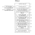
- FIG. 2 is a block diagram of the auxiliary feedwater valve control apparatus according to the present embodiment.
- the auxiliary feedwater valve control apparatus includes a water-level detection means 125 that detects a water level of secondary cooling water in the steam generator 103.
- the auxiliary feedwater valve control apparatus also includes a control means 1 that controls the auxiliary feedwater valve 123 based on the water level detected by the water-level detection means 125.
- the control means 1 is constituted by a microcomputer or the like, and includes a storage means 2, a water-level-deviation calculation means 3, a valve-operation setting means 4, and a valve drive means 5.
- the storage means 2 is constituted by a random access memory (RAM) or a read only memory (ROM), and programs and data are stored therein.
- the storage means 2 stores therein information of a preset target value (a target water level) of a water level to be maintained (target water level information).
- the storage means 2 also stores therein information specific to the auxiliary feedwater valve 123 (valve specific information).
- the valve specific information includes an opening/closing operation speed of the auxiliary feedwater valve 123, the number of opening/closing operations per unit time of the auxiliary feedwater valve 123, and a total operating time in the unit time of the auxiliary feedwater valve 123.
- the opening/closing operation speed of the auxiliary feedwater valve 123 is measured in advance in the auxiliary feedwater valve 123 to be used, and the number of opening/closing operations per unit time of the auxiliary feedwater valve, 123 and the total operating time in the unit time of the auxiliary feedwater valve 123 are mechanical restrictions according to a structure of the auxiliary feedwater valve 123 to be used.
- the storage means 2 also stores therein information of a time response of a water level corresponding to the aperture of the auxiliary feedwater valve 123 (water-level time-response information).
- the water-level time-response information is acquired by a simulation in which the nuclear power plant described above is simulated (for example, see Japanese Patent Application Laid-open No.
- the storage means 2 stores therein a non-minimum phase transfer function (see the following expression 1).
- s denotes a Laplace operator
- a, b, and k are parameters for determining a time response of a water level.
- the water-level-deviation calculation means 3 calculates a deviation between a target water level stored in the storage means 2 and a water level detected by the water-level detection means 125.
- the valve-operation setting means 4 includes a valve-aperture setting means 4a, a valve-driving-time setting means 4b, a valve-control-cycle setting means 4c, a one-cycle control-time setting means 4d, and an inverse-response-addition setting means 4e.
- the valve-aperture setting means 4a sets an aperture of the auxiliary feedwater valve 123 corresponding to a deviation of a water level calculated by the water-level-deviation calculation means 3.
- the aperture of the auxiliary feedwater valve 123 corresponds to a feed amount (a flow rate) of auxiliary cooling water passing through the auxiliary feedwater valve 123, while setting that a feeding amount of auxiliary cooling water fed by the auxiliary feed water pump 122 is constant.
- the valve-driving-time setting means 4b sets a driving time of the auxiliary feedwater valve 123 corresponding to the aperture of the auxiliary feedwater valve 123 set by the valve-aperture setting means 4a based on the opening/closing operation speed of the auxiliary feedwater valve 123 stored in the storage means 2. That is, the driving time of the auxiliary feedwater valve 123 is a time during which the auxiliary feedwater valve 123 is driven until the auxiliary feedwater valve 123 has the set aperture. Specifically, when a deviation between the target water level and the detected water level is large, the driving time of the auxiliary feedwater valve 123 becomes long, and when the deviation between the target water level and the detected water level is small, the driving time of the auxiliary feedwater valve 123 becomes short.
- the valve-control-cycle setting means 4c sets a driving cycle of the auxiliary feedwater valve 123 corresponding to the driving time of the auxiliary feedwater valve 123 set by the valve-driving-time setting means 4b and the number of opening/closing operations per unit time of the auxiliary feedwater valve 123 stored in the storage means 2. In this manner, the valve-control-cycle setting means 4c sets the driving cycle, that is, the number of times of driving of the auxiliary feedwater valve 123 until the water level reaches the target water level, under a restriction of the number of operations of the auxiliary feedwater valve 123.
- the one-cycle control-time setting means 4d sets the driving cycle of the auxiliary feedwater valve 123 corresponding to the driving time of the auxiliary feedwater valve 123 set by the valve-driving-time setting means 4b and the number of opening/closing operations per unit time of the auxiliary feedwater valve 123 stored in the storage means 2, and sets the longest driving time per driving cycle corresponding to the set driving cycle of the auxiliary feedwater valve 123 and the total operating time in the unit time of the auxiliary feedwater valve 123 stored in the storage means 2.
- the one-cycle control-time setting means 4d sets the driving cycle, that is, the number of times of driving of the auxiliary feedwater valve 123 until the water level reaches the target water level, under a restriction of the number of operations of the auxiliary feedwater valve 123, and sets the longest driving time per driving cycle, that is, the longest time during which the auxiliary feedwater valve 123 can be driven in one driving cycle, under a restriction of the total operating time in the unit time of the auxiliary feedwater valve 123.
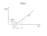
- FIG. 3 is a conceptual diagram of an inverse response.
- Xp denotes a maximum inverse response amount
- Tp denotes a maximum inverse response time
- Tr denotes an inverse response time
- V denotes a steady-water-level change speed.
- the inverse-response-addition setting means 4e acquires the water-level time-response information and the non-minimum phase transfer function stored in the storage means 2, determines a parameter in the non-minimum phase transfer function, which approximates a response to the water level from the aperture of the auxiliary feedwater valve 123 set by the valve-aperture setting means 4a by the inverse response, based on the water-level time-response information, and sets the aperture of the auxiliary feedwater valve 123, taking into consideration a gain margin and a phase margin of frequency characteristics of the non-minimum phase transfer function in which the parameter has been determined.
- Approximation of a response to the water level from the aperture of the auxiliary feedwater valve 123 is performed based on the following expression 2, while designating that Laplace-transformed temporal variation of the auxiliary feedwater valve 123 is H(s), and Laplace-transformed temporal variation of the water level of the steam generator 103 is L(s).
- Xp, Tp, and Tr increase with an increase in temperature, corresponding to the temperature of secondary cooling water in the steam, generator 103.
- the inverse-response-addition setting means 4e respectively obtains the aperture of the auxiliary feedwater valve 123 corresponding to the deviation of the water level under different temperature conditions of secondary cooling water in the steam generator 103 included in the water-level time-response information, and a minimum value thereof is selected.
- the valve drive means 5 outputs a signal for driving the auxiliary feedwater valve 123 corresponding to the setting by the valve-operation setting means 4.
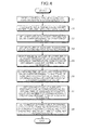
- FIG. 4 is a flowchart of an operation of the auxiliary feedwater valve control apparatus.
- the water-level detection means 125 first detects a water level of secondary cooling water in the steam generator 103 (Step S1).
- the water-level-deviation calculation means 3 then calculates a deviation between the target level the detected water level (Step S2).
- the valve-operation setting means 4 then sets the aperture of the auxiliary feedwater valve 123 corresponding to the deviation of the water level (Step S3).
- Step S3 the inverse-response-addition setting means 4e sets the aperture of the auxiliary feedwater valve 123 according to the inverse response (Step S4).
- the inverse-response-addition setting means 4e selects the minimum amount of the aperture of the auxiliary feedwater valve 123 based on the different temperature conditions of secondary cooling water in the steam generator 103 (Step S5).
- the valve-driving-time setting means 4b sets the driving time of the auxiliary feedwater valve 123 corresponding to the aperture of the auxiliary feedwater valve 123, based on the opening/closing operation speed of the auxiliary feedwater valve 123 (Step S6).
- the valve-control-cycle setting means 4c sets the driving cycle of the auxiliary feedwater valve 123 corresponding to the driving time of the auxiliary feedwater valve 123 and the number of opening/closing operations per unit time of the auxiliary feedwater valve 123 (Step S7).
- the driving time of the auxiliary feedwater valve 123 set by the valve-driving-time setting means 4b is relatively short (when the deviation between the target water level and the detected water level is relatively small)
- the water level reaches the target water level more quickly by extending the driving cycle (educing the number of times of driving) of the auxiliary feedwater valve 123.
- the driving time of the auxiliary feedwater valve 123 set by the valve-driving-time setting means 4b is relatively long (when the deviation between the target water level and the detected water level is relatively large), the water level reaches the target water level, while the water level is stabilized by finely adjusting the aperture, by shortening the driving cycle (increasing the number of times of driving) of the auxiliary feedwater valve 123.
- the one-cycle control-time setting means 4d sets the longest driving time per driving cycle corresponding to the driving cycle of the auxiliary feedwater valve 123 and the total operating time in the unit time of the auxiliary feedwater valve 123 (Step S8).
- the driving time of the auxiliary feedwater valve 123 set by the valve-driving-time setting means 4b is relatively short (when the deviation between the target water level and the detected water level is relatively small)
- the water level reaches the target water level more quickly by extending the driving cycle (reducing the number of times of driving) of the auxiliary feedwater valve 123 and setting the longest driving time per driving cycle relatively long.
- the driving time of the auxiliary feedwater valve 123 set by the valve-driving-time setting means 4b is relatively long (when the deviation between the target water level and the detected water level is relatively large), the water level reaches the target water level, while the water level is stabilized by finely adjusting the aperture, by shortening the driving cycle (increasing the number of times of driving) of the auxiliary feedwater valve 123 and setting the longest driving time per driving cycle relatively short.
- Step S8 the valve drive means 5 outputs a signal for driving the auxiliary feedwater valve 123, to finish the control.
- Step S6 If addition of the inverse response is not taken into consideration, subsequent to Step S3, the process proceeds to Step S6. If there is no influence of the temperature of secondary cooling water in the steam generator 103 in the inverse response, subsequent to Step S4, the process proceeds to Step S6. Furthermore, if the number of opening/closing operations per unit time of the auxiliary feedwater valve 123 and the total operating time in the unit time of the auxiliary feedwater valve 123 are not defined, the valve drive means 5 outputs a signal for driving the auxiliary feedwater valve 123 subsequent to Step S6, to finish the control. Further, if the total operating time in the unit time of the auxiliary feedwater valve 123 is not defined, subsequent to Step S7, the valve drive means 5 outputs a signal for driving the auxiliary feedwater valve 123, to finish the control.
- the auxiliary feedwater valve control apparatus of a steam generator includes the water-level detection means 125 that detects the water level of secondary cooling water in the steam generator 103, the water-level-deviation calculation means 3 that calculates a deviation between a preset target water level and a water level detected by the water-level detection means 125, the valve-operation setting means 4 (the valve-aperture setting means 4a) that sets the aperture of the auxiliary feedwater valve 123 corresponding to the deviation of the water level, and the valve drive means 5 that outputs a signal for driving the auxiliary feedwater valve 123 corresponding to the setting by the valve-operation setting means 4.
- the auxiliary feedwater valve 123 is operated without corresponding to operations of an operator and water level control of secondary cooling water in the steam generator 103 can be automatically performed.
- the valve-operation setting means 4 includes the valve-driving-time setting means 4b that sets the driving time of the auxiliary feedwater valve 123 corresponding to the aperture of the auxiliary feedwater valve 123 set by the valve-aperture setting means 4a or the inverse-response-addition setting means 4e based on an opening/closing operation speed of the auxiliary feedwater valve 123 measured in advance.
- the driving time of the auxiliary feedwater valve 123 for realizing the set aperture of the auxiliary feedwater valve 123 is set based on the opening/closing operation speed of the auxiliary feedwater valve 123. Accordingly, the aperture of the auxiliary feedwater valve 123 can be controlled corresponding to the performance of the auxiliary feedwater valve 123.
- the valve-operation setting means 4 includes the valve-driving-time setting means 4b that sets the driving time of the auxiliary feedwater valve 123 corresponding to the aperture of the auxiliary feedwater valve 123 set by the valve-aperture setting means 4a or the inverse-response-addition setting means 4e based on the opening/closing operation speed of the auxiliary feedwater valve 123 measured in advance, and the valve-control-cycle setting means 4c that sets the driving cycle of the auxiliary feedwater valve 123 corresponding to the set driving time of the auxiliary feedwater valve 123 and the number of opening/closing operations per unit time of the auxiliary feedwater valve 123.
- the driving cycle of the auxiliary feedwater valve 123 is set corresponding to the driving time of the auxiliary feedwater valve 123 set by the valve-driving-time setting means 4b and the number of opening/closing operations per unit time of the auxiliary feedwater valve 123, thereby enabling to perform appropriate water level control until the water level reaches the target water level.
- the valve-operation setting means 4 includes the valve-driving-time setting means 4b that sets the driving time of the auxiliary feedwater valve 123 corresponding to the aperture of the auxiliary feedwater valve 123 set by the valve-aperture setting means 4a or the inverse-response-addition setting means 4e based on the opening/closing operation speed of the auxiliary feedwater valve 123 measured in advance, the valve-control-cycle setting means 4c that sets the driving cycle of the auxiliary feedwater valve 123 corresponding to the set driving time of the auxiliary feedwater valve 123 and the number of opening/closing operations per unit time of the auxiliary feedwater valve 123, and the one-cycle control-time setting means 4d that sets the longest driving time per driving cycle corresponding to the set driving cycle of the auxiliary feedwater valve 123
- the driving cycle of the auxiliary feedwater valve 123 is set corresponding to the driving time of the auxiliary feedwater valve 123 set by the valve-driving-time setting means 4b and the number of opening/closing operations per unit time of the auxiliary feedwater valve 123, and the longest driving time per driving cycle is set corresponding to the set driving cycle of the auxiliary feedwater valve 123 and the total operating time in the unit time of the auxiliary feedwater valve 123, thereby enabling to perform appropriate water level control until the water level reaches the target water level.
- the valve-operation setting means 4 includes the inverse-response-addition setting means 4e that acquires the water-level time-response information corresponding to the aperture of the auxiliary feedwater valve 123 in advance, determines a parameter in the non-minimum phase transfer function, which approximates a response to the water level by the inverse response from the aperture of the auxiliary feedwater valve 123 set by the valve-aperture setting means 4a, based on the water-level time-response information, and sets the aperture of the auxiliary feedwater valve 123, taking into consideration a gain margin and a phase margin of frequency characteristics of the non-minimum phase transfer function in which the parameter has been determined.
- auxiliary feedwater valve control apparatus of a steam generator water level variation at the time of an inverse response can be suppressed by setting the aperture of the auxiliary feedwater valve 123 according to the inverse response.
- the inverse-response-addition setting means 4e of the valve-operation setting means 4 obtains the aperture of the auxiliary feedwater valve 123, respectively, under different temperature conditions of secondary cooling water in the steam generator 103 included in the water-level time-response information, and selects a minimum value thereof.
- a temperature detection means (not shown) that detects the temperature of secondary cooling water in the steam generator 103 can be provided, and the aperture of the auxiliary feedwater valve 123 can be set by matching the temperature detected by the temperature detection means with the temperature condition, thereby enabling to suppress water level variation at the time of an inverse response with any temperature.
Landscapes
- Engineering & Computer Science (AREA)
- Physics & Mathematics (AREA)
- Chemical & Material Sciences (AREA)
- General Engineering & Computer Science (AREA)
- Combustion & Propulsion (AREA)
- Thermal Sciences (AREA)
- Mechanical Engineering (AREA)
- Chemical Kinetics & Catalysis (AREA)
- Plasma & Fusion (AREA)
- High Energy & Nuclear Physics (AREA)
- Control Of Steam Boilers And Waste-Gas Boilers (AREA)
- Control Of Turbines (AREA)
Applications Claiming Priority (1)
| Application Number | Priority Date | Filing Date | Title |
|---|---|---|---|
| JP2011235475A JP5964029B2 (ja) | 2011-10-26 | 2011-10-26 | 蒸気発生器の補助給水弁制御装置 |
Publications (3)
| Publication Number | Publication Date |
|---|---|
| EP2587142A2 true EP2587142A2 (de) | 2013-05-01 |
| EP2587142A3 EP2587142A3 (de) | 2018-04-11 |
| EP2587142B1 EP2587142B1 (de) | 2020-09-09 |
Family
ID=47115496
Family Applications (1)
| Application Number | Title | Priority Date | Filing Date |
|---|---|---|---|
| EP12189861.3A Active EP2587142B1 (de) | 2011-10-26 | 2012-10-25 | Steuerungsvorrichtung für ein Speisewasserhilfsventil eines Dampferzeugers |
Country Status (3)
| Country | Link |
|---|---|
| US (1) | US9208905B2 (de) |
| EP (1) | EP2587142B1 (de) |
| JP (1) | JP5964029B2 (de) |
Cited By (1)
| Publication number | Priority date | Publication date | Assignee | Title |
|---|---|---|---|---|
| GB2535834A (en) * | 2015-01-08 | 2016-08-31 | China Nuclear Power Eng Co Ltd | Method for segmental control of auxillary feedwater flow |
Families Citing this family (4)
| Publication number | Priority date | Publication date | Assignee | Title |
|---|---|---|---|---|
| KR101481155B1 (ko) * | 2012-12-26 | 2015-01-09 | 한국전력기술 주식회사 | 원전 증기발생기의 수위 변화율에 따른 이득 조절장치 및 방법 |
| KR101654096B1 (ko) * | 2015-04-17 | 2016-09-07 | 한국원자력연구원 | 자가진단 사고대처 무인 원자로 |
| KR101881328B1 (ko) * | 2016-09-08 | 2018-07-24 | 한국남동발전 주식회사 | 발전소에서 pid제어기의 적분동작을 이용한 주밸브 조작요구량에 따른 보조밸브 제어방법 |
| CN114459013B (zh) * | 2022-01-27 | 2023-09-08 | 华能山东石岛湾核电有限公司 | 高温气冷堆蒸汽发生器的保护系统及方法 |
Citations (3)
| Publication number | Priority date | Publication date | Assignee | Title |
|---|---|---|---|---|
| JPS6396405A (ja) | 1986-09-29 | 1988-04-27 | ウエスチングハウス・エレクトリック・コーポレーション | 蒸気発生器への給水流量制御方法 |
| JPH06231109A (ja) | 1993-02-02 | 1994-08-19 | Mitsubishi Heavy Ind Ltd | 実機プラント運転支援システム |
| JPH086483A (ja) | 1994-06-21 | 1996-01-12 | Mitsubishi Heavy Ind Ltd | パートタスク運転の可能なフルスケール運転訓練シミュレータ |
Family Cites Families (35)
| Publication number | Priority date | Publication date | Assignee | Title |
|---|---|---|---|---|
| JPS4814083Y1 (de) * | 1969-02-26 | 1973-04-18 | ||
| US4123909A (en) * | 1976-12-20 | 1978-11-07 | Combustion Engineering, Inc. | Turbine trip system |
| US4104117A (en) * | 1977-02-07 | 1978-08-01 | Westinghouse Electric Corp. | Nuclear reactor power generation |
| US4231328A (en) * | 1978-07-18 | 1980-11-04 | Westinghouse Electric Corp. | Automatic steam generator feedwater realignment system |
| FR2476369B1 (fr) * | 1980-02-15 | 1985-06-14 | Framatome Sa | Procede de regulation de la puissance fournie par un reacteur nucleaire a eau sous pression a une turbine a vapeur |
| JPS56117196A (en) * | 1980-02-22 | 1981-09-14 | Hitachi Ltd | Nuclear reactor water level control device |
| JPS56149504A (en) * | 1980-04-21 | 1981-11-19 | Hitachi Ltd | Water level control of water feed heater |
| JPS57129301A (en) * | 1981-02-04 | 1982-08-11 | Hitachi Ltd | Auxiliary cooler for steam generator |
| JPS5864503A (ja) * | 1981-10-14 | 1983-04-16 | Hitachi Ltd | 装置の異常状態に対する原因推定方法 |
| JPS5924102A (ja) * | 1982-07-29 | 1984-02-07 | 三菱重工業株式会社 | 蒸気発生器の内部水位制御装置 |
| JPS60135899A (ja) * | 1983-12-26 | 1985-07-19 | 株式会社日立製作所 | 原子炉給水制御方法 |
| JPH0686922B2 (ja) * | 1984-08-17 | 1994-11-02 | 株式会社日立製作所 | ボイラドラムレベル制御装置 |
| JPS62293003A (ja) * | 1986-06-11 | 1987-12-19 | 三菱重工業株式会社 | 蒸気発生器の給水制御装置 |
| US4777009A (en) * | 1986-06-30 | 1988-10-11 | Combustion Engineering, Inc. | Automatic steam generator feedwater control over full power range |
| JPS6334405A (ja) * | 1986-07-28 | 1988-02-15 | 株式会社日立製作所 | 給水ポンプの再循環流量制御装置 |
| US4753770A (en) * | 1987-02-12 | 1988-06-28 | Institutul De Studii Si Proiectari Energetice | Control system for heat supply as hot water from nuclear power plants equipped with condensation units |
| US4847039A (en) * | 1987-10-13 | 1989-07-11 | Westinghouse Electric Corp. | Steam chest crossties for improved turbine operations |
| US4832898A (en) * | 1987-11-25 | 1989-05-23 | Westinghouse Electric Corp. | Variable delay reactor protection system |
| JPH036498A (ja) * | 1989-06-05 | 1991-01-11 | Toshiba Corp | 原子炉起動停止時水位制御装置 |
| JP2582437B2 (ja) * | 1989-06-09 | 1997-02-19 | 三菱重工業株式会社 | プラント運転ガイダンス装置 |
| JP2599026B2 (ja) * | 1990-10-12 | 1997-04-09 | 動力炉・核燃料開発事業団 | 給水調節弁切替時の蒸気ドラム水位制御方法 |
| JP2538894Y2 (ja) * | 1991-02-20 | 1997-06-18 | 三菱重工業株式会社 | 加圧器水位制御装置 |
| JPH05142390A (ja) * | 1991-11-19 | 1993-06-08 | Hitachi Ltd | 給水制御装置 |
| JP3333674B2 (ja) * | 1995-12-01 | 2002-10-15 | 株式会社日立製作所 | プラント運転計画作成方法および装置 |
| JP3649511B2 (ja) * | 1996-04-15 | 2005-05-18 | 三菱重工業株式会社 | スウェリング発生予知検出装置およびボイラ給水制御装置 |
| KR19980024802A (ko) * | 1996-09-30 | 1998-07-06 | 존 에이치. 물홀랜드 | 펌프 선택 논리 회로 |
| JPH10122506A (ja) | 1996-10-22 | 1998-05-15 | Mitsubishi Heavy Ind Ltd | 蒸気発生器の給水制御装置 |
| JPH11325407A (ja) * | 1998-05-08 | 1999-11-26 | Mitsubishi Heavy Ind Ltd | 蒸気発生器の水位制御装置 |
| FR2827997B1 (fr) * | 2001-07-24 | 2005-10-07 | Framatome Anp | Procede et dispositif d'alimentation d'au moins un generateur de vapeur d'un reacteur nucleaire a eau sous pression pendant les periodes d'arret du reacteur |
| JP2003139302A (ja) * | 2001-11-05 | 2003-05-14 | Toshiba Corp | 復水器の補給水供給装置 |
| US7120218B2 (en) * | 2002-09-25 | 2006-10-10 | Westinghouse Electric Co, Llc | Method for calibrating steam generator water level measurement |
| JP2007170814A (ja) * | 2007-03-19 | 2007-07-05 | Meidensha Corp | ボイラドラムの水位制御装置 |
| JP4982507B2 (ja) * | 2009-01-09 | 2012-07-25 | 株式会社日立製作所 | タービングランドシール蒸気減温制御装置および蒸気タービン発電設備におけるプラント制御方法 |
| JP5773565B2 (ja) * | 2009-10-29 | 2015-09-02 | 三菱重工業株式会社 | 原子力発電プラントの運転支援装置及び運転支援方法 |
| JP5276614B2 (ja) * | 2010-02-25 | 2013-08-28 | 株式会社日立製作所 | 貫流型ボイラ |
-
2011
- 2011-10-26 JP JP2011235475A patent/JP5964029B2/ja active Active
-
2012
- 2012-10-25 US US13/660,369 patent/US9208905B2/en active Active
- 2012-10-25 EP EP12189861.3A patent/EP2587142B1/de active Active
Patent Citations (3)
| Publication number | Priority date | Publication date | Assignee | Title |
|---|---|---|---|---|
| JPS6396405A (ja) | 1986-09-29 | 1988-04-27 | ウエスチングハウス・エレクトリック・コーポレーション | 蒸気発生器への給水流量制御方法 |
| JPH06231109A (ja) | 1993-02-02 | 1994-08-19 | Mitsubishi Heavy Ind Ltd | 実機プラント運転支援システム |
| JPH086483A (ja) | 1994-06-21 | 1996-01-12 | Mitsubishi Heavy Ind Ltd | パートタスク運転の可能なフルスケール運転訓練シミュレータ |
Cited By (2)
| Publication number | Priority date | Publication date | Assignee | Title |
|---|---|---|---|---|
| GB2535834A (en) * | 2015-01-08 | 2016-08-31 | China Nuclear Power Eng Co Ltd | Method for segmental control of auxillary feedwater flow |
| GB2535834B (en) * | 2015-01-08 | 2019-04-10 | China Nuclear Power Eng Co Ltd | Method for segmental control of auxillary feedwater flow |
Also Published As
| Publication number | Publication date |
|---|---|
| US20130108003A1 (en) | 2013-05-02 |
| JP5964029B2 (ja) | 2016-08-03 |
| EP2587142B1 (de) | 2020-09-09 |
| JP2013092476A (ja) | 2013-05-16 |
| EP2587142A3 (de) | 2018-04-11 |
| US9208905B2 (en) | 2015-12-08 |
Similar Documents
| Publication | Publication Date | Title |
|---|---|---|
| EP2587142B1 (de) | Steuerungsvorrichtung für ein Speisewasserhilfsventil eines Dampferzeugers | |
| US10208964B2 (en) | Steam cooking oven and method | |
| EP2390565B1 (de) | Abhitzedampferzeuger-System und Verfahren zur Regelung des Wasserstandes in einer Dampf-Trommel eines Abhitzedampferzeugers für ein Kombi-Kraftwerk | |
| US10060297B2 (en) | Apparatus and method for reactor power control of steam turbine power generation system | |
| CN112628721B (zh) | 锅炉湿态运行给水控制方法、装置及存储介质 | |
| US20110023487A1 (en) | Method for controlling a steam generator and control circuit for a steam generator | |
| CN103941763B (zh) | 锅炉给水除氧器的升温自动控制方法与系统 | |
| SE426756B (sv) | Syrsystem for matarvattnet vid ett kernkraftverk | |
| US10982567B2 (en) | Condensate and feedwater system of steam power plant and operation method for the same | |
| CN107590586B (zh) | 核电厂非核蒸汽冲转瞬态试验控制方法及控制装置 | |
| US4339410A (en) | Control for liquid plant | |
| JP2010159713A (ja) | タービングランドシール蒸気減温制御装置および蒸気タービン発電設備におけるプラント制御方法 | |
| CN114242284A (zh) | 一种核反应堆热工水力试验系统及调控方法 | |
| Palenzuela et al. | Operational improvements to increase the efficiency of an absorption heat pump connected to a multi-effect distillation unit | |
| CN105937413A (zh) | 一种利用非核蒸汽进行汽轮机冲转的系统及方法 | |
| CN110056849B (zh) | 废热回收锅炉的供水方法及废热回收锅炉 | |
| CN107543141A (zh) | 升温升压过程中蒸汽发生器模拟体给水系统及控制方法 | |
| CN111255531B (zh) | 核电站汽轮机的进汽门带负荷开关试验及其参数确定方法 | |
| KR102042653B1 (ko) | 열교환기의 유량조절장치 | |
| CN113191093B (zh) | 压水堆二回路汽水流动模型建立方法及多工况模拟方法 | |
| JP5705600B2 (ja) | 主蒸気湿分測定装置、主蒸気湿分測定方法及び原子力発電プラント | |
| JPS6124679B2 (de) | ||
| JP5737881B2 (ja) | 原子力発電プラント及び原子炉冷却材圧力制御装置 | |
| CN107817209A (zh) | 阻垢缓蚀剂性能测试动态模拟装置及其控制方法 | |
| JP2799506B2 (ja) | 貫流ボイラの起動制御装置 |
Legal Events
| Date | Code | Title | Description |
|---|---|---|---|
| PUAI | Public reference made under article 153(3) epc to a published international application that has entered the european phase |
Free format text: ORIGINAL CODE: 0009012 |
|
| AK | Designated contracting states |
Kind code of ref document: A2 Designated state(s): AL AT BE BG CH CY CZ DE DK EE ES FI FR GB GR HR HU IE IS IT LI LT LU LV MC MK MT NL NO PL PT RO RS SE SI SK SM TR |
|
| AX | Request for extension of the european patent |
Extension state: BA ME |
|
| PUAL | Search report despatched |
Free format text: ORIGINAL CODE: 0009013 |
|
| AK | Designated contracting states |
Kind code of ref document: A3 Designated state(s): AL AT BE BG CH CY CZ DE DK EE ES FI FR GB GR HR HU IE IS IT LI LT LU LV MC MK MT NL NO PL PT RO RS SE SI SK SM TR |
|
| AX | Request for extension of the european patent |
Extension state: BA ME |
|
| RIC1 | Information provided on ipc code assigned before grant |
Ipc: F22B 35/00 20060101AFI20180308BHEP Ipc: F22B 37/46 20060101ALI20180308BHEP |
|
| STAA | Information on the status of an ep patent application or granted ep patent |
Free format text: STATUS: REQUEST FOR EXAMINATION WAS MADE |
|
| 17P | Request for examination filed |
Effective date: 20180703 |
|
| RBV | Designated contracting states (corrected) |
Designated state(s): AL AT BE BG CH CY CZ DE DK EE ES FI FR GB GR HR HU IE IS IT LI LT LU LV MC MK MT NL NO PL PT RO RS SE SI SK SM TR |
|
| GRAP | Despatch of communication of intention to grant a patent |
Free format text: ORIGINAL CODE: EPIDOSNIGR1 |
|
| STAA | Information on the status of an ep patent application or granted ep patent |
Free format text: STATUS: GRANT OF PATENT IS INTENDED |
|
| INTG | Intention to grant announced |
Effective date: 20200617 |
|
| GRAS | Grant fee paid |
Free format text: ORIGINAL CODE: EPIDOSNIGR3 |
|
| GRAA | (expected) grant |
Free format text: ORIGINAL CODE: 0009210 |
|
| STAA | Information on the status of an ep patent application or granted ep patent |
Free format text: STATUS: THE PATENT HAS BEEN GRANTED |
|
| RAP1 | Party data changed (applicant data changed or rights of an application transferred) |
Owner name: MITSUBISHI HEAVY INDUSTRIES, LTD. |
|
| AK | Designated contracting states |
Kind code of ref document: B1 Designated state(s): AL AT BE BG CH CY CZ DE DK EE ES FI FR GB GR HR HU IE IS IT LI LT LU LV MC MK MT NL NO PL PT RO RS SE SI SK SM TR |
|
| REG | Reference to a national code |
Ref country code: GB Ref legal event code: FG4D |
|
| REG | Reference to a national code |
Ref country code: AT Ref legal event code: REF Ref document number: 1312026 Country of ref document: AT Kind code of ref document: T Effective date: 20200915 Ref country code: CH Ref legal event code: EP |
|
| REG | Reference to a national code |
Ref country code: DE Ref legal event code: R096 Ref document number: 602012072205 Country of ref document: DE |
|
| REG | Reference to a national code |
Ref country code: IE Ref legal event code: FG4D |
|
| REG | Reference to a national code |
Ref country code: LT Ref legal event code: MG4D |
|
| PG25 | Lapsed in a contracting state [announced via postgrant information from national office to epo] |
Ref country code: SE Free format text: LAPSE BECAUSE OF FAILURE TO SUBMIT A TRANSLATION OF THE DESCRIPTION OR TO PAY THE FEE WITHIN THE PRESCRIBED TIME-LIMIT Effective date: 20200909 Ref country code: BG Free format text: LAPSE BECAUSE OF FAILURE TO SUBMIT A TRANSLATION OF THE DESCRIPTION OR TO PAY THE FEE WITHIN THE PRESCRIBED TIME-LIMIT Effective date: 20201209 Ref country code: NO Free format text: LAPSE BECAUSE OF FAILURE TO SUBMIT A TRANSLATION OF THE DESCRIPTION OR TO PAY THE FEE WITHIN THE PRESCRIBED TIME-LIMIT Effective date: 20201209 Ref country code: FI Free format text: LAPSE BECAUSE OF FAILURE TO SUBMIT A TRANSLATION OF THE DESCRIPTION OR TO PAY THE FEE WITHIN THE PRESCRIBED TIME-LIMIT Effective date: 20200909 Ref country code: GR Free format text: LAPSE BECAUSE OF FAILURE TO SUBMIT A TRANSLATION OF THE DESCRIPTION OR TO PAY THE FEE WITHIN THE PRESCRIBED TIME-LIMIT Effective date: 20201210 Ref country code: HR Free format text: LAPSE BECAUSE OF FAILURE TO SUBMIT A TRANSLATION OF THE DESCRIPTION OR TO PAY THE FEE WITHIN THE PRESCRIBED TIME-LIMIT Effective date: 20200909 Ref country code: LT Free format text: LAPSE BECAUSE OF FAILURE TO SUBMIT A TRANSLATION OF THE DESCRIPTION OR TO PAY THE FEE WITHIN THE PRESCRIBED TIME-LIMIT Effective date: 20200909 |
|
| REG | Reference to a national code |
Ref country code: AT Ref legal event code: MK05 Ref document number: 1312026 Country of ref document: AT Kind code of ref document: T Effective date: 20200909 |
|
| REG | Reference to a national code |
Ref country code: NL Ref legal event code: MP Effective date: 20200909 |
|
| PG25 | Lapsed in a contracting state [announced via postgrant information from national office to epo] |
Ref country code: LV Free format text: LAPSE BECAUSE OF FAILURE TO SUBMIT A TRANSLATION OF THE DESCRIPTION OR TO PAY THE FEE WITHIN THE PRESCRIBED TIME-LIMIT Effective date: 20200909 Ref country code: PL Free format text: LAPSE BECAUSE OF FAILURE TO SUBMIT A TRANSLATION OF THE DESCRIPTION OR TO PAY THE FEE WITHIN THE PRESCRIBED TIME-LIMIT Effective date: 20200909 Ref country code: RS Free format text: LAPSE BECAUSE OF FAILURE TO SUBMIT A TRANSLATION OF THE DESCRIPTION OR TO PAY THE FEE WITHIN THE PRESCRIBED TIME-LIMIT Effective date: 20200909 |
|
| PG25 | Lapsed in a contracting state [announced via postgrant information from national office to epo] |
Ref country code: CZ Free format text: LAPSE BECAUSE OF FAILURE TO SUBMIT A TRANSLATION OF THE DESCRIPTION OR TO PAY THE FEE WITHIN THE PRESCRIBED TIME-LIMIT Effective date: 20200909 Ref country code: EE Free format text: LAPSE BECAUSE OF FAILURE TO SUBMIT A TRANSLATION OF THE DESCRIPTION OR TO PAY THE FEE WITHIN THE PRESCRIBED TIME-LIMIT Effective date: 20200909 Ref country code: NL Free format text: LAPSE BECAUSE OF FAILURE TO SUBMIT A TRANSLATION OF THE DESCRIPTION OR TO PAY THE FEE WITHIN THE PRESCRIBED TIME-LIMIT Effective date: 20200909 Ref country code: PT Free format text: LAPSE BECAUSE OF FAILURE TO SUBMIT A TRANSLATION OF THE DESCRIPTION OR TO PAY THE FEE WITHIN THE PRESCRIBED TIME-LIMIT Effective date: 20210111 Ref country code: RO Free format text: LAPSE BECAUSE OF FAILURE TO SUBMIT A TRANSLATION OF THE DESCRIPTION OR TO PAY THE FEE WITHIN THE PRESCRIBED TIME-LIMIT Effective date: 20200909 Ref country code: SM Free format text: LAPSE BECAUSE OF FAILURE TO SUBMIT A TRANSLATION OF THE DESCRIPTION OR TO PAY THE FEE WITHIN THE PRESCRIBED TIME-LIMIT Effective date: 20200909 |
|
| REG | Reference to a national code |
Ref country code: DE Ref legal event code: R119 Ref document number: 602012072205 Country of ref document: DE |
|
| PG25 | Lapsed in a contracting state [announced via postgrant information from national office to epo] |
Ref country code: AT Free format text: LAPSE BECAUSE OF FAILURE TO SUBMIT A TRANSLATION OF THE DESCRIPTION OR TO PAY THE FEE WITHIN THE PRESCRIBED TIME-LIMIT Effective date: 20200909 Ref country code: AL Free format text: LAPSE BECAUSE OF FAILURE TO SUBMIT A TRANSLATION OF THE DESCRIPTION OR TO PAY THE FEE WITHIN THE PRESCRIBED TIME-LIMIT Effective date: 20200909 Ref country code: IS Free format text: LAPSE BECAUSE OF FAILURE TO SUBMIT A TRANSLATION OF THE DESCRIPTION OR TO PAY THE FEE WITHIN THE PRESCRIBED TIME-LIMIT Effective date: 20210109 Ref country code: ES Free format text: LAPSE BECAUSE OF FAILURE TO SUBMIT A TRANSLATION OF THE DESCRIPTION OR TO PAY THE FEE WITHIN THE PRESCRIBED TIME-LIMIT Effective date: 20200909 |
|
| REG | Reference to a national code |
Ref country code: CH Ref legal event code: PL |
|
| PG25 | Lapsed in a contracting state [announced via postgrant information from national office to epo] |
Ref country code: LU Free format text: LAPSE BECAUSE OF NON-PAYMENT OF DUE FEES Effective date: 20201025 Ref country code: MC Free format text: LAPSE BECAUSE OF FAILURE TO SUBMIT A TRANSLATION OF THE DESCRIPTION OR TO PAY THE FEE WITHIN THE PRESCRIBED TIME-LIMIT Effective date: 20200909 Ref country code: SK Free format text: LAPSE BECAUSE OF FAILURE TO SUBMIT A TRANSLATION OF THE DESCRIPTION OR TO PAY THE FEE WITHIN THE PRESCRIBED TIME-LIMIT Effective date: 20200909 |
|
| REG | Reference to a national code |
Ref country code: BE Ref legal event code: MM Effective date: 20201031 |
|
| PLBE | No opposition filed within time limit |
Free format text: ORIGINAL CODE: 0009261 |
|
| STAA | Information on the status of an ep patent application or granted ep patent |
Free format text: STATUS: NO OPPOSITION FILED WITHIN TIME LIMIT |
|
| PG25 | Lapsed in a contracting state [announced via postgrant information from national office to epo] |
Ref country code: DE Free format text: LAPSE BECAUSE OF NON-PAYMENT OF DUE FEES Effective date: 20210501 |
|
| 26N | No opposition filed |
Effective date: 20210610 |
|
| GBPC | Gb: european patent ceased through non-payment of renewal fee |
Effective date: 20201209 |
|
| PG25 | Lapsed in a contracting state [announced via postgrant information from national office to epo] |
Ref country code: CH Free format text: LAPSE BECAUSE OF NON-PAYMENT OF DUE FEES Effective date: 20201031 Ref country code: BE Free format text: LAPSE BECAUSE OF NON-PAYMENT OF DUE FEES Effective date: 20201031 Ref country code: DK Free format text: LAPSE BECAUSE OF FAILURE TO SUBMIT A TRANSLATION OF THE DESCRIPTION OR TO PAY THE FEE WITHIN THE PRESCRIBED TIME-LIMIT Effective date: 20200909 Ref country code: SI Free format text: LAPSE BECAUSE OF FAILURE TO SUBMIT A TRANSLATION OF THE DESCRIPTION OR TO PAY THE FEE WITHIN THE PRESCRIBED TIME-LIMIT Effective date: 20200909 Ref country code: LI Free format text: LAPSE BECAUSE OF NON-PAYMENT OF DUE FEES Effective date: 20201031 |
|
| PG25 | Lapsed in a contracting state [announced via postgrant information from national office to epo] |
Ref country code: IT Free format text: LAPSE BECAUSE OF FAILURE TO SUBMIT A TRANSLATION OF THE DESCRIPTION OR TO PAY THE FEE WITHIN THE PRESCRIBED TIME-LIMIT Effective date: 20200909 Ref country code: IE Free format text: LAPSE BECAUSE OF NON-PAYMENT OF DUE FEES Effective date: 20201025 |
|
| PG25 | Lapsed in a contracting state [announced via postgrant information from national office to epo] |
Ref country code: GB Free format text: LAPSE BECAUSE OF NON-PAYMENT OF DUE FEES Effective date: 20201209 |
|
| PG25 | Lapsed in a contracting state [announced via postgrant information from national office to epo] |
Ref country code: IS Free format text: LAPSE BECAUSE OF FAILURE TO SUBMIT A TRANSLATION OF THE DESCRIPTION OR TO PAY THE FEE WITHIN THE PRESCRIBED TIME-LIMIT Effective date: 20210109 Ref country code: TR Free format text: LAPSE BECAUSE OF FAILURE TO SUBMIT A TRANSLATION OF THE DESCRIPTION OR TO PAY THE FEE WITHIN THE PRESCRIBED TIME-LIMIT Effective date: 20200909 Ref country code: MT Free format text: LAPSE BECAUSE OF FAILURE TO SUBMIT A TRANSLATION OF THE DESCRIPTION OR TO PAY THE FEE WITHIN THE PRESCRIBED TIME-LIMIT Effective date: 20200909 Ref country code: CY Free format text: LAPSE BECAUSE OF FAILURE TO SUBMIT A TRANSLATION OF THE DESCRIPTION OR TO PAY THE FEE WITHIN THE PRESCRIBED TIME-LIMIT Effective date: 20200909 |
|
| PG25 | Lapsed in a contracting state [announced via postgrant information from national office to epo] |
Ref country code: MK Free format text: LAPSE BECAUSE OF FAILURE TO SUBMIT A TRANSLATION OF THE DESCRIPTION OR TO PAY THE FEE WITHIN THE PRESCRIBED TIME-LIMIT Effective date: 20200909 |
|
| P01 | Opt-out of the competence of the unified patent court (upc) registered |
Effective date: 20230522 |
|
| PGFP | Annual fee paid to national office [announced via postgrant information from national office to epo] |
Ref country code: FR Payment date: 20250908 Year of fee payment: 14 |