EP2586888A1 - Bogenverdampfungsquelle mit hoher filmbildungsgeschwindigkeit, filmbildungsvorrichtung und herstellungsverfahren für einen beschichtungsfilm mit der bogenverdampfungsquelle - Google Patents
Bogenverdampfungsquelle mit hoher filmbildungsgeschwindigkeit, filmbildungsvorrichtung und herstellungsverfahren für einen beschichtungsfilm mit der bogenverdampfungsquelle Download PDFInfo
- Publication number
- EP2586888A1 EP2586888A1 EP11797792.6A EP11797792A EP2586888A1 EP 2586888 A1 EP2586888 A1 EP 2586888A1 EP 11797792 A EP11797792 A EP 11797792A EP 2586888 A1 EP2586888 A1 EP 2586888A1
- Authority
- EP
- European Patent Office
- Prior art keywords
- target
- magnet
- permanent magnet
- evaporation source
- arc
- Prior art date
- Legal status (The legal status is an assumption and is not a legal conclusion. Google has not performed a legal analysis and makes no representation as to the accuracy of the status listed.)
- Granted
Links
Images


Classifications
-
- C—CHEMISTRY; METALLURGY
- C23—COATING METALLIC MATERIAL; COATING MATERIAL WITH METALLIC MATERIAL; CHEMICAL SURFACE TREATMENT; DIFFUSION TREATMENT OF METALLIC MATERIAL; COATING BY VACUUM EVAPORATION, BY SPUTTERING, BY ION IMPLANTATION OR BY CHEMICAL VAPOUR DEPOSITION, IN GENERAL; INHIBITING CORROSION OF METALLIC MATERIAL OR INCRUSTATION IN GENERAL
- C23C—COATING METALLIC MATERIAL; COATING MATERIAL WITH METALLIC MATERIAL; SURFACE TREATMENT OF METALLIC MATERIAL BY DIFFUSION INTO THE SURFACE, BY CHEMICAL CONVERSION OR SUBSTITUTION; COATING BY VACUUM EVAPORATION, BY SPUTTERING, BY ION IMPLANTATION OR BY CHEMICAL VAPOUR DEPOSITION, IN GENERAL
- C23C14/00—Coating by vacuum evaporation, by sputtering or by ion implantation of the coating forming material
- C23C14/22—Coating by vacuum evaporation, by sputtering or by ion implantation of the coating forming material characterised by the process of coating
- C23C14/34—Sputtering
- C23C14/35—Sputtering by application of a magnetic field, e.g. magnetron sputtering
-
- B—PERFORMING OPERATIONS; TRANSPORTING
- B23—MACHINE TOOLS; METAL-WORKING NOT OTHERWISE PROVIDED FOR
- B23K—SOLDERING OR UNSOLDERING; WELDING; CLADDING OR PLATING BY SOLDERING OR WELDING; CUTTING BY APPLYING HEAT LOCALLY, e.g. FLAME CUTTING; WORKING BY LASER BEAM
- B23K9/00—Arc welding or cutting
-
- C—CHEMISTRY; METALLURGY
- C23—COATING METALLIC MATERIAL; COATING MATERIAL WITH METALLIC MATERIAL; CHEMICAL SURFACE TREATMENT; DIFFUSION TREATMENT OF METALLIC MATERIAL; COATING BY VACUUM EVAPORATION, BY SPUTTERING, BY ION IMPLANTATION OR BY CHEMICAL VAPOUR DEPOSITION, IN GENERAL; INHIBITING CORROSION OF METALLIC MATERIAL OR INCRUSTATION IN GENERAL
- C23C—COATING METALLIC MATERIAL; COATING MATERIAL WITH METALLIC MATERIAL; SURFACE TREATMENT OF METALLIC MATERIAL BY DIFFUSION INTO THE SURFACE, BY CHEMICAL CONVERSION OR SUBSTITUTION; COATING BY VACUUM EVAPORATION, BY SPUTTERING, BY ION IMPLANTATION OR BY CHEMICAL VAPOUR DEPOSITION, IN GENERAL
- C23C14/00—Coating by vacuum evaporation, by sputtering or by ion implantation of the coating forming material
- C23C14/22—Coating by vacuum evaporation, by sputtering or by ion implantation of the coating forming material characterised by the process of coating
- C23C14/24—Vacuum evaporation
- C23C14/32—Vacuum evaporation by explosion; by evaporation and subsequent ionisation of the vapours, e.g. ion-plating
- C23C14/325—Electric arc evaporation
-
- H—ELECTRICITY
- H01—ELECTRIC ELEMENTS
- H01J—ELECTRIC DISCHARGE TUBES OR DISCHARGE LAMPS
- H01J37/00—Discharge tubes with provision for introducing objects or material to be exposed to the discharge, e.g. for the purpose of examination or processing thereof
- H01J37/32—Gas-filled discharge tubes
- H01J37/32009—Arrangements for generation of plasma specially adapted for examination or treatment of objects, e.g. plasma sources
- H01J37/32055—Arc discharge
-
- H—ELECTRICITY
- H01—ELECTRIC ELEMENTS
- H01J—ELECTRIC DISCHARGE TUBES OR DISCHARGE LAMPS
- H01J37/00—Discharge tubes with provision for introducing objects or material to be exposed to the discharge, e.g. for the purpose of examination or processing thereof
- H01J37/32—Gas-filled discharge tubes
- H01J37/34—Gas-filled discharge tubes operating with cathodic sputtering
- H01J37/3402—Gas-filled discharge tubes operating with cathodic sputtering using supplementary magnetic fields
Definitions
- the present invention concerns a film formation apparatus used for improvement of wear resistance of mechanical parts, etc., and forming a thin film such as a ceramic film, for example, of a nitride and an oxide, and an amorphous carbon film. Further, the present invention concerns an arc evaporation source used for the film formation apparatus and a method for manufacturing a coating film using the arc evaporation source.
- physical vapor deposition methods such as an arc ion plating method and a sputtering method have been known generally as a technique of coating a thin film on the surface of a substrate such as mechanical parts, cutting tools, and sliding parts.
- a cathode discharge arc evaporation source is used.
- the cathode discharge arc evaporation source generates arc discharge on the surface of a target as a cathode.
- a material constituting the target is melted instantaneously and ionized.
- a thin film is formed by drawing the ionized material to the surface of the substrate as a work.
- the arc evaporation source has a fast evaporation speed and high ionization rate for the evaporated material constituting the target. Accordingly a dense coating film can be formed by applying a bias to the substrate upon film formation. Accordingly, the arc evaporation source is used industrially for forming a wear resistant coating film, for example, on a cutting tool.
- the amount of the molten target material (macro particle) released from the arc spot tends to be suppressed when the arc spot transfers at a high speed. It has been known that the transfer speed of the arc spot undergoes the effect of a magnetic field applied to the target.
- target atoms evaporated by arc discharge are electrolytically dissociated, that is, ionized in the arc plasma.
- the track of ions from the target to the substrate undergoes the effect of a magnetic field between the target and the substrate.
- compressive stress in a coating film obtained by PVD film formation such as film formation by cathode discharge type arc evaporation source, compressive stress remains in principle.
- the compressive stress tends to be increased as the thickness of the coating film is larger.
- -2 GPa compressive stress ⁇ -2 GPa
- adhesion of the coating film to the tool is lowered and tends to cause peeling.
- the thickness of the coating film covering the cutting tool can be increased, the life of the cutting tool can be extended.
- Patent literature 1 describes an arc evaporation source having a ring shaped magnetic force generation mechanism (permanent magnet, solenoid coil) disposed to the circumference of a target and applying a vertical magnetic field to the surface of the target.
- Patent literature 2 describes an ion plating device having a magnetic force generation mechanism (solenoid coil) disposed ahead of the target so as to converge the ionized material constituting the target efficiently in the direction of the substrate.
- Patent literature 3 describes an evaporation source for an arc ion plating device having a permanent magnet disposed to the central position at the rear surface of the target, a ring shaped magnet disposed at the rear surface of the target so as to surround the permanent magnet and having a polarity different from that of the permanent magnet, and a solenoid coil forming a magnetic field component so as to confine arc discharge and having a diameter substantially equal with that of the ring shaped magnet.
- Patent literature 4 describes an arc vapor deposition apparatus having a ring shaped magnet disposed to the circumference of a target and a solenoid coil disposed at the rear surface of the target and forming a magnetic field in parallel with the surface of the target by the solenoid coil.
- arc discharge tends to be generated preferentially at a point where the vertical component of the magnetic field (component in the vertical direction of the magnetic field to the surface of the target) is decreased to 0. Accordingly, even when the solenoid coil is used, the position where the arc discharge is generated is trapped substantially at an intermediate portion between the permanent magnet and the ring shaped magnet and it is difficult to control the position to a further inner circumferential portion. Accordingly, the efficiency of utilizing the target cannot be improved. Further, in the arrangement described in the Patent literature 3, there is no component of the lines of magnetic force extending forwardly from the target. Accordingly, ions emitted from the target are not efficiently converged to the substrate.
- the Patent literature 4 only describes an embodiment in which the inner diameter of the solenoid coil is smaller than the diameter of the target. In this case, the lines of magnetic force tend to be diverged from the target to the outside and it is considered that ions cannot be converged efficiently. Further, in the arc vapor deposition apparatus described in the Patent literature 4, discharge of arc plasma is transferred at a high speed in order to obtain a strength necessary for the magnetic field parallel to the surface of the target. Accordingly, in combination with the solenoid coil (or magnetic body yoke), it is necessary to supply a large current to a large-sized solenoid coil to increase the size of the evaporation source which is not preferred industrially.
- An object of the present invention is to provide an arc evaporation source having a high film-forming speed, a manufacturing method for a coating film and a film formation apparatus using the arc evaporation source.
- the present invention provides an arc evaporation source of generating arc discharge to the surface of a target thereby melting the target including, at least one circumference magnet disposed so as to surround the circumference of the target and such that the direction of magnetization thereof is in perpendicular to the surface of the target, a non-ring shaped first permanent magnet disposed on the side of the rear surface of the target, having a polarity in the same direction as the polarity of the circumference magnet, and such that the direction of magnetization thereof is in perpendicular to the surface of the target, a non-ring shaped second permanent magnet disposed between the first permanent magnet and the target or on the side of the rear surface of the first permanent magnet in a state of leaving a gap to the first permanent magnet, having a polarity in the same direction as the polarity of the circumference magnet, and such that the direction of magnetization thereof is in perpendicular to the surface of the target, and a magnetic body disposed between the first permanent magnet and the second permanent magnet.
- the present invention provides a method for manufacturing a coating film including a coating film forming step of forming a coating film by using the arc evaporation source.
- the present invention provides a film formation apparatus including the arc evaporation source and an arc power source that applies a voltage to the arc evaporation source for generating arc discharge.
- the film-forming speed of the film formation apparatus using the arc evaporation source can be increased.
- Fig. 1 shows a film formation apparatus 6 of a first embodiment having an arc evaporation sources 1 (hereinafter referred to as evaporation source 1) according to an embodiment of the invention.
- the film formation apparatus 6 has a vacuum chamber 11, a rotary base 12 disposed in the vacuum chamber 11 and supporting a substrate 7 as a work, an evaporation source 1 partially disposed in the vacuum chamber 11 and attached being directed to the substrate 7, an arc power source 15 for applying a negative bias to the evaporation source 1, and a bias power source 16 for applying a negative bias to the substrate 7.
- the vacuum chamber 11 is provided with a gas introduction port 13 for introducing a reaction gas into the vacuum chamber 11 and a gas exhaust port 14 for exhausting the reaction gas from the inside of the vacuum chamber 11.
- the arc power source 15 applies a negative bias to a target 2 of the evaporation source 1 to be described later.
- the positive electrode of the arc power source 15 and the positive side of the bias power source 16 are connected to the ground 18 respectively.
- the evaporation source 1 has a disk shaped (hereinafter "disk shaped" also means a cylindrical shape having a predetermined height) target 2, a magnetic field forming means 8 disposed near the target 2, and an anode 17 disposed to the circumference of the target 2.
- the anode 17 is connected to the ground 18, and also the vacuum chamber 11 at the same potential as that of the anode 17 can operate as the anode 17. That is, the evaporation source 1 is a cathode discharge type arc evaporation source.
- the target 2 comprises a material selected in accordance with a thin film to be formed on the substrate 7 (for example, chromium (Cr), titanium (Ti), titanium aluminum (TiAl), or carbon (C)).
- a material selected in accordance with a thin film to be formed on the substrate 7 for example, chromium (Cr), titanium (Ti), titanium aluminum (TiAl), or carbon (C)).
- the magnetic field forming means 8 has a circumference magnet 3 disposed so as to surround the circumference of the target 2, a rear surface magnet 4 and the magnetic body 5 disposed on the side of the rear surface of the target 2.
- the circumference magnet 3 and the rear surface magnet 4 are disposed such that the direction of the polarity of the circumference magnet 3 and the direction of the polarity of the rear surface magnet 4 are identical.
- the circumference magnet 3 is disposed in the vacuum chamber 11 and the rear surface magnet 4 and the magnetic body 5 are disposed outside of the vacuum chamber 11.
- the evaporation surface of the target 2 (surface on the side of the substrate 7) is referred to as “frontal surface” and the surface on the opposite side is referred to as “rear surface” (refer to Fig. 2 and Fig. 3 ).
- the circumference magnet 3 and the rear surface magnet 4 comprise a permanent magnet formed of a neodymium magnet having high coercivity.
- the circumference magnet 3 is ring shaped and disposed so as to be coaxial with the target 2.
- the circumference magnet 3 is disposed so that the direction is along the axis of the target 2 (perpendicular to the evaporation surface of a material constituting the target 2). Further, the circumference magnet 3 is disposed such that the projected plane in the radial direction of the circumference magnet 3 overlaps with the projected plane in the radial direction of the target 2. That is, the circumference magnet 3 is disposed such that shadows formed by projecting the circumference magnet 3 and the target 2 in the direction parallel to the evaporation surface of the target 2 overlap with each other.
- the circumference magnet 3 may be formed also by disposing a plurality of permanent magnets of a cylindrical shape or the like so as to surround the circumference of the target 2 (circular shape). That is, "ring shape” also includes a state of arranging a plurality of magnets along the circumference of the target 2.
- the rear surface magnet 4 is disposed such that the direction of magnetization thereof is along with the axis of the target 2 (perpendicular to the evaporation surface of the material constituting the target 2) and on the side of the rear surface of the target.
- the rear surface magnet 4 has a polarity in the same direction as the polarity of the circumference magnet 3. Specifically, for each of the circumference magnet 3 and the rear surface magnet 4 in Fig. 2 and Fig. 3 , the polarity on the side near the substrate 7 is an N-pole, and the polarity on the side remote from the substrate 7 is an S-pole. On the contrary, the circumference magnet 3 and the rear surface magnet 4 may be disposed such that the polarity on the side near the substrate 7 is the S-pole and the polarity on the side remote from the substrate 7 is the N-pole.
- the magnetic field forming means 8 has the configuration as described above. Therefore, it is possible to guide the lines of magnetic force in the direction of the substrate 7 by the combination of a magnetic field formed by the circumference magnet 3 disposed to the circumference of the target 2 and a magnetic field formed by the rear surface magnet 4 disposed on the side of the rear surface of the target 2.
- the rear surface magnet 4 in this embodiment is non-ring shaped as in disk shaped rear surface magnets 4A, 4B to be described later.
- Non-ring shape means those different from doughnut's shape not having a hole in the radial inside but those of solid shape filled with contents, and includes also disk shape, circular cylindrical shape, etc.
- non-ring shape means such a shape that none of normal lines directing from the surface to the outward intersect to each other.
- Fig. 2 shows a magnetic field forming means 8 of Example 1.
- the rear surface magnet 4 has a disk shaped rear surface magnet 4A (first permanent magnet) and another disk shaped rear surface magnet 4B (second permanent magnet) disposed at the rear surface of the disk shaped rear surface magnet 4A.
- the magnetic body 5 is disposed between the disk shaped rear surface magnet 4A and the disk shaped rear surface magnet 4B.
- Fig. 3 shows a magnetic field forming means 8 of Example 2.
- the arrangement of the first permanent magnet 4A and the second permanent magnet 4B is replaced while keeping the direction of the poles and the direction of magnetization.
- the inside of the vacuum chamber 11 is evacuated by depressurizing the inside of the vacuum chamber 11. Then, an argon gas (Ar) or the like is introduced from the gas introduction port 13. Then, impurities such as oxides on the target 2 and the substrate 7 are removed by sputtering and the inside of the vacuum chamber 11 is again evacuated. Then, a reaction gas is introduced from gas introduction port 13 into the vacuum chamber 11. In this state, arc discharge is generated on the target 2 disposed to the vacuum chamber 11 thereby evaporating and ionizing the material constituting the target 2 and reacting the same with the reaction gas. Thus, a nitride film, oxide film, carbide film, carbonitride film, or amorphous carbon film is formed on the substrate 7 placed on the rotary base 12.
- Ar argon gas
- reaction gas a nitrogen gas (N 2 ), an oxygen gas (O 2 ), or a hydrocarbon gas such as methane (CH 4 ) may be selected according to the application use.
- the pressure of the reaction gas in the vacuum chamber 11 is set to about 1 to 7 Pa.
- the arc discharge current during film formation is set to 100 to 200 A.
- a negative voltage at 10 to 200 V is applied to the substrate 7 from the bias power source 16.
- Example 1 using the evaporation source 1 according to the invention is to be described.
- the rear surface magnet 4 has a disk shaped (columnar) permanent magnet (hereinafter referred to as “disk shaped rear surface magnet 4A (first permanent magnet)”), and the other disk shaped permanent magnet (hereinafter referred to as “disk shaped rear surface magnet 4B (second permanent magnet)”) disposed on the side of the rear surface of the disk shaped rear surface magnet 4A (on the side opposite to the substrate 7) leaving a gap relative to the disk shaped rear surface magnet 4A.
- a disk shaped magnetic body 5 is provided between the disk shaped rear surface magnets 4A and 4B.
- shape of projected plane is similar to the shape of projected plane of the target 2. Further, the axial line of each of the disk shaped rear surface magnets 4A and 4B, the axial line of the magnetic body 5, and the axial line of the target 2 are situated respectively on one identical straight line.
- Each of the disk shaped rear surface magnets 4A and 4B is formed of a neodymium magnet of high coercivity. Accordingly, the entire magnetic field forming means 8 can be made compact.
- the magnetic body 5 is formed of easily available and inexpensive carbon steel, the material of the magnetic body is not restricted thereto but the magnetic body 5 can be formed, for example, of a material having a specific magnetic permeability of more than 1. This is because any material having a specific magnetic permeability more than 1 can be served as a magnetic guide.
- the magnetic body 5 is formed of the material having a specific magnetic permeability of 250 or more, the function of the magnetic body 5 as a magnetic guide is improved. Specifically, cobalt (specific magnetic permeability: 250), nickel (specific magnetic permeability: 600), carbon steel (specific magnetic permeability: 1,000), iron (specific magnetic permeability: 5,000), ferrosilicon (specific magnetic permeability: 7,000), pure iron (specific magnetic permeability: 200,000), etc. are preferably used as the material for the magnetic body 5.
- Both end faces of the magnetic body 5 axe in close contact with the end face of the disk shaped rear surface magnet 4A (first permanent magnet) on the side of the rear surface (opposite to the substrate 7) and the end face of the disk shaped rear surface magnet 4B (second permanent magnet) on the side of the substrate 7, respectively.
- Example 2 is different from Example 1 only in that the position for the first permanent magnet 4A and the position for the second permanent magnet 4B are replaced to each other. That is, each of the permanent magnets 4A and 4B has an identical shape.
- Example 2 is to be described together.
- the diameter of the target 2 is 100 mm.
- the thickness of the target 2 is 16 mm.
- the target 2 is formed of titanium aluminum (TiAl) with the atomic ratio of titanium (Ti) and aluminum (Al) of 1:1.
- the outer diameter of the circumference magnet 3 is 170 mm.
- the inner diameter of the circumference magnet 3 is 150 mm.
- the thickness of the circumference magnet 3 is 10 mm.
- Nitrogen (N 2 ) is selected as the reaction gas in Example 1.
- the pressure of the reaction gas is 4 Pa.
- the film formation time is 30 min.
- the arc discharge current is 150 A.
- a negative voltage at 30 V is applied to the substrate 7 by using the bias power source 16.
- the substrate 7 is a chip of a mirror polished super hard alloy sized 15 mm x 15 mm x 5 mm. Further, the substrate 7 is disposed at a position apart by about 180 mm from the surface of the target 2. The temperature of the substrate 7 is set to 500°C.
- Comparative Example 1 to Comparative Example 4 shown in Fig. 4 to Fig. 7 the conditions for the target 2, the circumference magnet 3, the arc current value, the reaction gas, the film formation time, the applied negative voltage, and the substrate 7 are identical.
- Comparative Example 1 is a comparative example not having the rear surface magnet 4 on the side of the rear surface of the target 2.
- Comparative Example 2 is a comparative example having two ring shaped permanent magnets disposed on the side of the rear surface of the target 2.
- the outer diameter of each of the two ring shaped permanent magnets disposed on the side of the rear surface of the target 2 is 100 mm.
- the inner diameter of each of the ring shaped permanent magnets is 80 mm.
- the thickness of each of the ring shaped permanent magnet is 10 mm.
- one of the ring shaped permanent magnets is disposed at a position of 60 mm from the surface of target 2 and the other of them is disposed at a position of 100 mm from the surface target 2.
- Comparative Example 3 is a comparative example having two ring shaped permanent magnets disposed on the side of the rear surface of the target 2 and carbon steel as a magnetic body disposed between each of the permanent magnets.
- the carbon steel as the magnetic body is disposed being in close contact with the two ring shaped permanent magnets.
- the shape of each of the permanent magnets and the distance of each of the permanent magnets from the surface of the target 2 are identical with those of Comparative Example 2.
- Comparative Example 4 is a comparative example having two disk shaped permanent magnets disposed on the side of the rear surface of the target 2. In Comparative Example 4, a magnetic body is not disposed between the two disk shaped permanent magnets.
- Table 1 shows the number of sheets of the rear surface magnets, the thickness of the rear surface magnets, the diameter for each of the magnets, the distance from the surface of the target 2, the value of current flowing to the substrate 7, evaluation for the film-forming speed, the value of film residual stress, and the result of evaluation for the residual film stress for Comparative Example 1 to Comparative Example 4 and Example 1 (also for Example 2).
- each of the magnets in the comparative examples are also defined as the first permanent magnet and the second permanent magnet for the sake of convenience.
- Example2 1010 - - 69,100 none 1.1 ⁇ -2.30 ⁇
- Example3 2 10,10 - - 60,100 present 12 ⁇ -2.25 x
- the film-forming speed is in proportion to an ionic current flowing to the substrate 7 by arc discharge. That is, as the value of current flowing to the substrate 7 is larger, the film-forming speed is higher.
- the current value in proportion to the film-forming speed is preferably 1.5 A or more. Accordingly, a current value of 1.5 A or more is evaluated as satisfactory.
- the residual stress in the thin film was calculated according to the Storney's equation shown in the formula (1). Specifically, film was formed on an Si wafer of 1 mm thickness, and the radius of curvature for the distortion of the substrate 7 after film formation was measured by utilizing an optical lever. The radius of curvature was used as the radius of curvature R in the formula (1). Assuming the peeling of a hard film for use in a cutting tool, the residual stress of the thin film at an absolute value of 2.0 GPa or less was evaluated as satisfactory.
- ⁇ f E s ⁇ t s 2 6 ⁇ R ⁇ 1 - v s ⁇ t f
- the distribution chart for lines of magnetic force of Comparative Example 1 is shown in Fig. 4 .
- the lines of magnetic force extending forward from the target 2 in Comparative Example 1 are greatly deviated from the frontal direction of the target 2 (that is, direction to the substrate 7).
- the distribution chart for lines of magnetic force in Comparative Example 2 is shown in Fig. 5 .
- the lines of magnetic force nearest to the axis of the target 2 are apart from the axis of the target 2 by about 24 mm already at a point where they progress by about 200 mm in the direction from the surface of the target 2 to the substrate 7 (refer to arrow B in Fig. 5 ).
- the distribution chart for lines of magnetic force of Comparative Example 3 is shown in Fig. 6 .
- the distribution chart for lines of magnetic force of Comparative Example 4 is shown in Fig. 7 .
- the lines of magnetic force nearest to the axis of the target 2 are apart by about 20 mm from the axis of the target 2 at a position of about 200 mm from the surface of the target 2 in the same manner as in Comparative Examples 1 and 2 (refer to arrow C in Fig. 6 and arrow D in Fig. 7 ).
- Comparative Examples 1 to 4 the track of ions is greatly deviated from the substrate 7 and the film-forming speed is slow. Accordingly, as shown in Table 1, the value of film residual stress in Comparative examples 1 to 4 show -2.40 GPa, -2.30 GPa, -2.25 GPa, and - 2.09 GPa, respectively. As a result, the film residual stress is also evaluated as failed. Accordingly, films with low film residual stress cannot be formed.
- Example 1 and Example 2 of the invention lines of magnetic force can be guided in the direction to the substrate 7 as shown in Fig. 8 .
- the lines of magnetic force nearest to the axis of the target 2 is not apart by 20 mm from the axis of the target 2 at a position progressing 200 mm in the direction from the surface of the target 2 to the substrate 7 (refer to arrow E in Fig. 8 ). Accordingly, a great amount of the lines of magnetic force can be guided to the substrate 7.
- Example 1 and Example 2 it takes a distance of about 1.30 mm in the direction from the surface of the target 2 to the substrate 7 for the lines of magnetic force most apart from the axis of the target 2 till they are apart by 200 mm from the axis of the target 2 (refer to arrow E' sin Fig. 7 ). Accordingly, a great amount of the lines of magnetic force extend in the direction from the target 2 to the substrate 7.
- both end faces of the magnetic body 5 are in close contact with end faces of the respective disk shaped rear surface magnets 4A and 4B.
- the lines of magnetic force extending from the end face of each of the disk shaped rear surface magnets 4A and 4B can be connected with no leakage.
- Example 1 and Example 2 absolute values of the film residual stress show 2.0 GPa or less. As a result, the film residual stress is evaluated as satisfactory. Accordingly, films of low residual stress can be formed.
- the diameter of the disk shaped rear surface magnets 4A and 4B and the magnetic body 5 may be 40 mm. That is, the area of the surface opposing the target 2 (hereinafter simply referred to as "surface") may be 400 ⁇ mm 2 . Thus, the surface are of the target 2 is 0.16 times (16/100) compared with the case where the diameter is 100 mm (in a case where the surface area is 2500 mm 2 ),
- the diameter of the disk shaped rear surface magnets 4A and 4B and the magnetic body 5 may be 80 mm. That is, the area of the surface of each of the magnets 4A and 4B, and the magnetic body 5 may be 1600 ⁇ mm 2 .
- the surface are of the target 2 is 0.64 times (64/100) compared with the case where the diameter is 100 mm (in a case where the surface area is 2500 ⁇ mm 2 ).
- the surface area of each of the disk shaped rear surface magnets 4A and 4B and the magnetic body 5 may be 0.25 times (1/4) or more of the surface area of the target 2. Also in this case, a larger amount of lines of magnetic force can be guided to the substrate 7 by suppressing deviation of the lines of magnetic force from the axis of the target 2. Thus, ions evaporated from the target 2 can be guided efficiently to the substrate 7.
- the surface area of the disk shaped rear surface magnets 4A and 4B and the magnetic body 5 is preferably 0.64 times (64/100) or more of the surface area of the target 2 and, more preferably, 1.0 times or more of the surface area of the target 2. Further, as a preferred upper limit, the diameter of the disk shaped rear surface magnets 4A and 4B is 1.5 times as large as the diameter of the target 2. That is, the surface area of the disk shaped rear surface magnets 4A and 4B is preferably 2.25 times (4/9) or less of the surface area of the target 2.
- the parallel component of the lines of magnetic force is increased at a position where the component of the lines of magnetic force perpendicular to the surface of the target 2 (hereinafter referred to as "vertical component") is at 0 (including values in the vicinity of 0 here and hereinafter). Further, arc discharge tends to be generated preferentially at the position where the vertical component of the line of magnetic force is at 0.
- the position where the vertical component is decreased to 0 is determined by the distance to the surface of the disk shaped rear surface magnet on the side near the surface of the target 2. Accordingly, when the distance is short, arc discharge tends to be generated at the circumferential portion and ions are generated at the outer side.
- the point where the vertical component of the lines of the magnetic force are at 0 is shifted to the central portion and the ions can reach the substrate 7 efficiently.
- a mechanism of moving each of the disk shaped rear surface magnets 4A and 4B and the magnetic body 5 forward and backward so as to approach or recede from the target 2 can be incorporated.
- the intensity of the parallel component of the lines of magnetic force can be controlled, as well as the point where the vertical component of the lines of magnetic force is at 0 can be controlled.
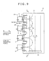
- Fig. 9 and Fig. 10 show a film formation apparatus 6 according to the second embodiment having a plurality of the arc evaporation sources 1 described above.
- each of the arc evaporation sources 1 is substantially identical with that of the first embodiment.
- the most prominent feature of the film formation apparatus 6 according to the second embodiment resides in the following points.
- a plurality (four sets) of arc evaporation sources 1 are provided (preparatory step). Then, for the plurality of the arc evaporation sources 1, a plurality (four sets) of evaporation sources 1 are disposed being arranged vertically so as to connect lines of magnetic force of adjacent arc evaporation sources 1 to each other (arrangement step). Specifically, the plurality of the evaporation sources 1 are disposed linearly or non-linearly (refer to Fig. 10(a), (b) ). Then, a coating film is formed by using the plurality of the arc evaporation sources 1 (coating film forming step).
- respective evaporation sources 1 are disposed such that the polarity (direction of pole) in the magnetic field forming means 8 (circumference magnet 3 and rear surface magnet 4) on the side near the substrate 7 are opposite between adjacent evaporation sources 1 to each other (opposite direction).
- the opposite arrangement is, for example, the following arrangement.
- a certain evaporation source 1 is disposed such that lines of magnetic force are directed in the direction to the substrate 7 (direction approaching from the target 2 to the substrate 7).
- an evaporation source 1 adjacent to the certain evaporation source 1 is disposed such that the lines of magnetic force are directed opposing the substrate 7 (direction receding from the substrate 7 to the target 2).
- the lines of magnetic force formed by the certain evaporation source 1 and the lines of magnetic force formed by the evaporation source 1 adjacent to the certain evaporation source 1 are connected to each other.
- the N-pole of the magnetic field forming means 8 of the uppermost evaporation source 1A is directed to the surface of the target 2 (side near the substrate 7) and the S-pole of the magnetic field forming means 8 of the second uppermost evaporation source 1B is directed to the surface of the target 2. Accordingly, lines of magnetic force from the uppermost evaporation source 1A to the second uppermost evaporation source 1B are generated between the uppermost evaporation source 1A and the second uppermost evaporation source 1B adjacent to each other (refer to Fig. 9 ).
- the lines of magnetic force between the uppermost evaporation source 1A and the second uppermost evaporation source 1B are in a closed state (closed region is referred to as "closed magnetic field region H"). Electrons emitted from the arc evaporation source 1 are trapped (confined) in the closed magnetic field region H. Thus, the emitted electrons are prevented from being drifted to the anode 17 or the vacuum chamber 11.
- the closed magnetic field region H is not restricted to the combination of the evaporation source 1A and the evaporation source 1B but is formed between other evaporation sources 1 adjacent to each other.
- the concentration of the emitted electrons increases in each of the closed magnetic field regions H and collision between the reaction gas and the emitted electrons in the vacuum chamber 11 increases at the periphery of the substrate 7.
- the reaction gas can be ionized at high efficiency.
- the film-forming speed is increased and the film can be formed further efficiently.
- Fig. 10 is a frontal projection view (on the side near the substrate 7) of arc evaporation sources 1 arranged in plurality (views along an arrow A-A in Fig. 9 ).
- a plurality of evaporation sources 1 can be arranged linearly in a vertical line.
- a plurality of evaporation sources 1 can be arranged non-linearly (for example, in a zigzag configuration).
- the left-to-right width of the closed magnetic field region H is narrowed. This can further increase the concentration of emitted electrons in the closed magnetic field region H and films can be formed to the substrate 7 at higher efficiency in the closed magnetic field region H.
- the width of the closed magnetic field region H is also increased by so much as a meandering width of the evaporation sources 1.
- films can be formed efficiently within the closed magnetic field region H.
- Linear arrangement includes not only the arrangement in one vertical row as described above but includes also an arrangement in one left-to-right row or arrangement in one oblique line in the inner surface of the vacuum chamber 11.
- the film formation apparatus 6 is configured such that the substrate 7 passes through the closed magnetic field region H described above.
- a plurality of substrates 7 are provided in plurality (for example, by the number of two in symmetrical with respect to the rotational axis) on the rotary base 12 in the vacuum chamber 11.
- substrates 7 on the rotary base 12 move so as to pass in front of the evaporation source 1 (on the frontal side of the target 2) successively.
- the configuration of passing the substrates 7 in the closed magnetic field region H is not restricted to the configuration of rotating the rotary base 12 or the substrate 7.
- the evaporation source 1 may be configured to go around the substrate 7. That is, it may suffice that the film formation apparatus 6 has means of relatively moving the substrate 7 to the closed magnetic field H successively.
- the film formation apparatus 6 according to the second embodiment may be in any other configuration. Further, the method for forming the film is identical with that in the first embodiment.
- Fig. 11 shows a film formation apparatus 6 according to a third embodiment having a plurality of the evaporation sources 1 described above.
- the third embodiment is different from the second embodiment in that a plurality (four sets) of evaporation sources 1 are arranged in a circular configuration (so as to surround the periphery of the substrates 7).
- the evaporation sources 1 adjacent to each other on a circumference are disposed such that the lines of magnetic force formed by respective evaporation source 1 are connected to each other.
- the direction of polarity (direction of pole) of magnetic field forming means 8 (circumference magnet 3, rear surface magnet 4, and magnetic body 5) of a certain evaporation source 1 is opposite to the direction of the polarity of the magnetic field forming means 8 of an evaporation source 1 adjacent to the certain evaporation source 1.
- the lines of magnetic force formed by the circumference magnet 3 and the rear surface magnet 4 are connected to each other by the arc evaporation sources 1 adjacent to each other.
- an N-pole of the magnetic field forming means 8 of an upper right evaporation source 1C in Fig. 11 is directed to the side of the surface of the target 2 (side near the substrate 7).
- An S pole of the magnetic field forming means 8 of the lower right evaporation source 1D of Fig. 11 is directed to the surface of the target 2. Accordingly, lines of magnetic force directing from the upper right evaporation source 1C to the lower right evaporation source 1D are generated.
- lines of magnetic force are connected also between other evaporation sources 1 adjacent to each other, other than the combination of the evaporation source 1C and the evaporation source 1D. Further, since the respective evaporation sources 1 are disposed circumferentially while surrounding the substrates 7, the lines of magnetic force from the respective sources are connected so as to surround the circumference of the substrates 7.
- the lines of magnetic force extending from each of the evaporation sources 1 are in a closed state surrounding a region including the substrates 7. Then, a closed magnetic field region H is generated in a wide range surrounding the substrates 7.
- "linear" arrangement includes not only the arrangement in one vertical row but also the following arrangements. Specifically, an arrangement of disposing a plurality of evaporation sources 1 at a predetermined height and disposing, in this state, the plurality of the evaporation sources 1 circumferentially so as to surround the substrates 7 is included. Further, “non-linear" arrangement in the third embodiment includes not only a vertically zigzag arrangement as described in the second embodiment but includes the following arrangement. Specifically, an arrangement of disposing a plurality of evaporation sources 1 such that the height from the bottom of the vacuum chamber 11 is different and disposing, in this state, the plurality of evaporation sources 1 circumferentially so as to surround the substrates 7 is included. Also in this embodiment, other portions than the rear surface magnet 4 and the magnetic body 5 of the plurality of evaporation sources 1 are disposed in the vacuum chamber 11.
- a plurality of substrates 7 are disposed (for example, by the number of two in symmetrical with respect to rotational axis) on a rotary base 12 in the vacuum chamber 11 such that the substrates 7 are situated in the wide closed magnet field region H as described above.
- the substrates 7 when the substrates 7 are rotated by the rotary base 12, the substrates 7 pass in front of each of the evaporation sources 1 successively. Therefore, films of identical or different composition and/or thickness can be formed successively over the substrates 7 by constituting the target 2 of each of the arc evaporation sources 1 with an identical or different material. As a result, when the material of the target 2 of each of the arc evaporation sources 1 is different, films of different materials can be formed in a multilayer.
- the film formation apparatus 6 according to the third embodiment may be in other configuration. Further, the method for forming the film is identical with that of the first embodiment.
- Fig. 12 shows a film formation apparatus 6 according to a fourth embodiment having a plurality of the arc evaporation sources 1 described above, and a plurality of sputtering evaporation sources 21 respectively.
- a plurality of evaporation sources 1 and 21 including two sets of arc evaporation sources 1 and two sets of sputtering evaporation sources 21 are provided (preparatory step). Then, the plurality of the evaporation sources 1 and 21 are disposed circumferentially such that lines of magnetic force of the adjacent evaporation sources 1 and 21 are connected to each other (arrangement step). Then, a film is formed by using the plurality of evaporation sources 1 and 21 (film forming step).
- the sputtering evaporation source 21 is a general sputtering evaporation source. Specifically, in the sputtering evaporation source.21, an inert gas (for example, argon (Ar), neon (Ne), or xenon (Xe)) introduced to the vacuum chamber 11 is ionized into plasmas by electric discharge and the plasma ions are caused to collide against (sputtered) the target 2 thereby flicking the target material to the substrate 7.
- an inert gas for example, argon (Ar), neon (Ne), or xenon (Xe)
- the magnetic field forming means 8 in the sputtering evaporation source 21 includes, as the rear surface magnet 4 of the target 2, a ring shaped magnet 4C (ring shaped permanent magnet) and a columnar magnet 4D (columnar permanent magnet) disposed inside the ring shaped magnet 4C and coaxially therewith.
- the ring shaped magnet 4C and the columnar magnet 4D are disposed such that the direction of the polarity of the ring shaped magnet 4C and the direction of the polarity of the columnar magnet 4D (direction of the pole) oppose to each other.
- lines of magnetic force are connected so as to surround the surface side of the target 2 between the ring shaped magnet 4C and the columnar magnet 4D to form a closed state near the surface of the target 2 (the closed region is referred to as "plasma closed magnetic field region H"').
- the adjacent evaporation sources 1 and 21 are disposed as below. Specifically, the polarity of the ring shaped magnet 4C of the sputtering evaporation source 21 and the direction of the pole of the magnetic field forming means 8 (circumference magnet 3 and rear surface magnet 4) of the arc evaporation source 1 adjacent to the sputtering evaporation source 21 are opposite to each other.
- the lines of magnetic force formed by the ring shaped magnet 4C of the sputtering evaporation source 21 and the magnetic field forming means 8 of the arc evaporation source 1 are connected to each other between the evaporation sources 1 and 21 adjacent to each other.
- the lines of magnetic force are connected so as to surround the circumference of the substrates 7 between each of the arc evaporation sources 1 and each of the sputtering evaporation sources 21.
- a closed magnetic field region H is generated separately from the plasma closed magnetic field region H' described above.
- the closed magnetic field region H is generated in a wide range surrounding the substrates 7.
- the concentration of the emitted electrons at the periphery of the substrates 7 can be increased in the closed magnetic field region while keeping a high plasma concentration near the sputtering evaporation source 21.
- a coating film can be formed on large size and large amount of the substrate simultaneously and at a high film-forming speed.
- a reaction gas such as nitrogen (N 2 ), methane (CH 4 ), and acetylene (C 2 H 2 ) is introduced into the vacuum chamber 11 or film formation is performed under a pressure of several Pa (about 1 to 7 Pa).
- an inert gas such as argon (Ar) is introduced into the vacuum chamber 11 and film formation is performed under a pressure of about several 0.1 Pa.
- a reaction gas such as nitrogen and an inert gas such as argon are used in admixture.
- the total pressure of the mixed atmosphere is set to about 2 to 4 Pa, and film is formed at a pressure lower than that in the film formation using only the arc evaporation source 1.
- the partial pressure of the reaction gas (nitrogen, etc.) is set to 0.5 to 2.65 Pa.
- the closed magnetic field region H and the plasma closed magnetic field region H' are separated by the lines of magnetic force respectively.
- the concentration of plasmas and the concentration of emitted electrons can be increased independently. Accordingly, the film-forming efficiency by the arc evaporation source 1 and the film-forming efficiency due to the sputtering evaporation source 21 can be improved simultaneously.
- the target 2 may be in any other shape than the disk shape.
- the shape of the projected plane of the target 2 may be a figure of a rotational symmetric body (square, hexagonal, etc.)
- the circumference magnet 3, the rear surface magnet 4, and the magnetic body 5 may not be disposed coaxially relative to the target 2.
- the circumference magnet 3, the rear surface magnet 4, and the magnetic body 5 are preferably disposed such that the central axis thereof (the rotational axis of the circumference magnet 3, the rear surface magnet 4, and the magnetic body 5 when they are rotational symmetric body) passes the target 2 .
- the target 2 may be of a figure where the shape of the projected plane has a longitudinal direction (elliptic, rectangular, etc.).
- the diameter can be read as a major diameter or a minor diameter.
- the shape of the projected plane of the target 2 is rectangular, the diameter can be read as a longer side or a shorter side.
- Any circumference magnet 3 that surrounds the circumference of the target 2 may be used.
- a ring shaped permanent magnet having a shape of the projected plane that can surround the shape of the projected plane of the target 2 can be adopted.
- a permanent magnet having an elliptic shape of the projected plane that can surround the target can be used.
- a circumference magnet 3 having the following shape may be used so long as it can surround the target 2.
- the circumference magnet 3 may be of a point symmetrical figure (square, hexagonal, etc.) or a figure having a longitudinal direction (elliptic, rectangular, etc.) corresponding to the shape of the projected plane of the target 2.
- the rear surface magnet 4 may be of any other shape than the disk-shape.
- the shape of the projected plane of the rear surface magnet 4 may be a point symmetric figure (square, hexagonal, etc.) or a figure having a longitudinal direction (elliptic, rectangular, etc.).
- the magnetic body 5 may be in any other shape than the disk shaped.
- the shape of the projected plane of the magnetic body 5 may be a point symmetric figure (square, hexagonal, etc.) or a figure having a longitudinal direction (elliptic, rectangular, etc.)
- the shape of projected plane of the rear surface magnet 4 and the magnetic body 5 is preferably similar to the shape of the projected plane of the target 2.
- circumference magnet 3, the rear surface magnet 4, and the magnetic body 5 may be disposed each in plurality.
- the evaporation source used for the film formation apparatus 6 is not restricted to the arc evaporation source 1 or the sputtering evaporation source 21 but may be a plasma beam evaporation source or an ohmic heating evaporation source.
- the present invention provides an arc evaporation source of generating arc discharge to the surface of a target thereby melting the target including, at least one circumference magnet disposed so as to surround the circumference of the target and such that the direction of magnetization thereof is in perpendicular to the surface of the target, a non-ring shaped first permanent magnet disposed on the side of the rear surface of the target, having a polarity in the same direction as the polarity of the circumference magnet, and disposed such that the direction of magnetization thereof is in perpendicular to the surface of the target, a non-ring shaped second permanent magnet disposed between the first permanent magnet and the target or on the side of the rear surface of the first permanent magnet in a state of leaving a gap to the first permanent magnet, having a polarity in the same direction as the polarity of the circumference magnet, and disposed such that the direction of magnetization thereof is in perpendicular to the surface of the target, and a magnetic body disposed between the first permanent magnet and the second permanent magnet.
- the circumference magnet is disposed to the circumference of the target, and magnets having the polarity in the same direction as the circumference magnet (first permanent magnet and the second permanent magnet) are disposed on the rear surface side of the target.
- a magnetic field of a large horizontal component is formed on the surface of the target (target evaporation surface), and repulsive magnetic fields are formed by both of the magnets on the surface of the target (both of the magnets of the circumference magnet, and the first permanent magnet and the second permanent magnet).
- the circumference magnet is disposed in order to surround the circumference of the target so that the horizontal component of the magnetic fields to be formed on the surface of the target is increased.
- a non-ring shaped permanent magnet having a polarity in the same direction as the polarity of the circumference magnet and disposed at the rear surface of the target (first permanent magnet) is provided. Then, a great amount of lines of magnetic force at high progression property extending from the central portion of the surface of the target to the substrate are generated.
- the direction of the magnetic pole of the first permanent magnet is made identical with the direction of the pole of the circumference magnet, and the shape of the first permanent magnet is formed as the non-ring shaped, in order to generate a great amount of lines of magnetic force at high straightness extending from the central portion at the surface (end face) of the target to the direction of the substrate.
- the particles evaporated and ionized from the target can be transported efficiently to the coating substrate. Therefore, the film-forming speed is improved.
- another permanent magnet (second permanent magnet) is disposed while leaving a gap relative to the first permanent magnet. This can improve the straightness of the lines of magnetic force generated from the central portion of the surface of the target.
- the first permanent magnet and the second permanent magnet are disposed at a gap as described above, in order to improve the degree of the straightness of the lines of magnetic force extending from the central portion of the surface of the target to the direction of the substrate.
- the most prominent feature of the invention is that a magnetic body is disposed between the first permanent magnet and the second permanent magnet. This can increase the number of lines of magnetic force at higher degree of straightness that are generated from the central portion of the surface of the target. That is, when the magnetic body is disposed between the first permanent magnet and the second permanent magnet, the lines of magnetic force extending from the surfaces (end faces) opposing to each other of each of the permanent magnets can be connected with no leakage and the number of lines of magnetic force at high straightness generated from the central portion of the surface of the target is further increased.
- ring shaped permanent magnet means not only the single permanent magnet having a ring shaped but also means a plurality of permanent magnets arranged in a ring shape. Further, “ring shape” is not restricted to a true circle but also includes an elliptic or polygonal shape.
- both end faces of the magnetic body are preferably adhered closely to the end face of the first permanent magnet and the end face of the second permanent magnet respectively.
- the lines of magnetic force extending from the end faces of the first permanent magnet and the second permanent magnet opposing to each other can be connected with no leakage.
- the target is disk shaped and the circumference magnet is a ring shaped permanent magnet.
- the direction of the lines of magnetic force ahead of the surface of the target can be directed to the substrate, the particles evaporated and ionized from the target can be transported efficiently to the coating substrate. Accordingly, the film-forming speed is improved.
- the shape of the plane formed by projecting the first permanent magnet and the second permanent magnet in the direction perpendicular to the surface thereof is preferably similar to the shape of the plane formed by projecting the target in the direction perpendicular to the surface thereof.
- the projected shapes of the first permanent magnet and the second permanent magnet are similar to the projected shape of the target.
- the lines of magnetic force extending from the first permanent magnet and the second permanent magnet to the target can be guided with no leakage to the target.
- the invention provides a method for manufacturing a coating film including a film forming step of forming a film by using the arc evaporation source.
- a coating film is formed by using the arc evaporation source in which a magnetic body is disposed between the first permanent magnet and the second permanent magnet.
- This can form a coating film in a state where a great amount of lines of magnetic force at high straightness is generated from the central portion of the surface of the target.
- electrons move while coiling around the lines of magnetic force and, at the same time, particles evaporated and ionized from the target move while being attracted to the electrons. Accordingly, particles evaporated and ionized from the target can be transported efficiently to the coating substrate by forming a coating film in a state of generating a great amount of lines of magnetic force at high straightness as described above. Accordingly, the film-forming speed can be improved.
- the method for manufacturing the coating film it is preferred to further include a preparatory step of providing a plurality of arc evaporation sources and an arrangement step of disposing the plurality of the arc evaporation sources so that the lines of magnetic force of the adjacent arc evaporation sources are connected to each other.
- the method for manufacturing the coating film it is preferred to further include a preparatory step of providing plural kinds of evaporation sources including the arc evaporation source, and an arrangement step of disposing the plural kinds of evaporation sources such that the lines of magnetic force of adj acent evaporation sources are connected to each other.
- a plurality of evaporation sources are disposed such that the lines of magnetic force of the adjacent evaporation sources are connected to each other. This provides a state in which the lines of magnetic force between adjacent evaporation sources are closed, and electrons emitted from the arc evaporation source can be confined within the closed region of the lines of magnetic force. As a result, the colliding probability of the electrons emitted from the arc evaporation source is increased to cause ionization of a reaction gas at high probability. Accordingly, the film-forming speed can be improved further by each of the embodiments described above.
- the plural kinds of arc evaporation sources can be disposed linearly or non-linearly.
- the plural kinds of arc evaporation sources can be disposed linearly or non-linearly.
- the present invention provides a film formation apparatus comprising the arc evaporation source and an arc power source that applies a voltage to the arc evaporation source for generating arc discharge.
- the film formation apparatus comprises an arc evaporation source in which a magnetic body is disposed between the first permanent magnet and the second permanent magnet, and an arc power source for applying a voltage to the arc evaporation source.
- This can generate a great amount of lines of magnetic force at high straightness from the central portion of the surface of the target.
- electrons move while coiling around the lines of magnetic force and, at the same time, particles evaporated and ionized from the target move while being attracted to the electrons. Accordingly, particles evaporated and ionized from the target can be transported efficiently to the coating substrate by generating a great amount of the lines of magnetic force at high straightness as described above. Accordingly, the film-forming step can be improved.
- the arc evaporation sources in plurality, in which the plurality of the arc evaporation sources are disposed such that the lines of magnetic force of the adjacent arc evaporation sources are connected to each other.
- evaporation sources including the arc evaporation source in which the plural kinds of evaporation sources are disposed such that the lines of magnetic force of adjacent evaporation sources are connected to each other.
- the plurality of evaporation sources are disposed such that the lines of magnetic force of adjacent evaporation sources are connected to each other. This provides a state where the lines of magnetic force between the adjacent evaporation sources are closed, and electrons emitted from the arc evaporation source can be confined within the closed region of the lines of magnetic force. As a result, the colliding probability of the electrons emitted from the arc evaporation source is increased and ionization of the reaction gas can be generated at high probability. Accordingly, the film-forming speed can be improved further according to each of the embodiments.
- the plurality of the arc evaporation sources can be disposed linearly or non-linearly.
- the plural kinds of the evaporation sources can be disposed linearly or non-linearly.
- the present inventions can be utilized as an arc evaporation source of a film formation apparatus for forming a thin film.
Landscapes
- Chemical & Material Sciences (AREA)
- Engineering & Computer Science (AREA)
- Physics & Mathematics (AREA)
- Plasma & Fusion (AREA)
- Mechanical Engineering (AREA)
- Analytical Chemistry (AREA)
- Chemical Kinetics & Catalysis (AREA)
- Materials Engineering (AREA)
- Metallurgy (AREA)
- Organic Chemistry (AREA)
- Physical Vapour Deposition (AREA)
Applications Claiming Priority (3)
| Application Number | Priority Date | Filing Date | Title |
|---|---|---|---|
| JP2010142614 | 2010-06-23 | ||
| JP2010201946A JP5318052B2 (ja) | 2010-06-23 | 2010-09-09 | 成膜速度が速いアーク式蒸発源、このアーク式蒸発源を用いた皮膜の製造方法及び成膜装置 |
| PCT/JP2011/003403 WO2011161903A1 (ja) | 2010-06-23 | 2011-06-15 | 成膜速度が速いアーク式蒸発源、このアーク式蒸発源を用いた皮膜の製造方法及び成膜装置 |
Publications (3)
| Publication Number | Publication Date |
|---|---|
| EP2586888A1 true EP2586888A1 (de) | 2013-05-01 |
| EP2586888A4 EP2586888A4 (de) | 2015-12-30 |
| EP2586888B1 EP2586888B1 (de) | 2016-11-23 |
Family
ID=45371110
Family Applications (1)
| Application Number | Title | Priority Date | Filing Date |
|---|---|---|---|
| EP11797792.6A Active EP2586888B1 (de) | 2010-06-23 | 2011-06-15 | Bogenverdampfungsquelle mit hoher filmbildungsgeschwindigkeit, filmbildungsvorrichtung und herstellungsverfahren für einen beschichtungsfilm mit der bogenverdampfungsquelle |
Country Status (10)
| Country | Link |
|---|---|
| US (1) | US9266180B2 (de) |
| EP (1) | EP2586888B1 (de) |
| JP (1) | JP5318052B2 (de) |
| KR (1) | KR101471269B1 (de) |
| CN (1) | CN102933738B (de) |
| BR (1) | BR112012033035B1 (de) |
| CA (1) | CA2801629C (de) |
| IL (1) | IL223408A (de) |
| PT (1) | PT2586888T (de) |
| WO (1) | WO2011161903A1 (de) |
Cited By (1)
| Publication number | Priority date | Publication date | Assignee | Title |
|---|---|---|---|---|
| WO2021001536A1 (en) * | 2019-07-03 | 2021-01-07 | Oerlikon Surface Solutions Ag, Pfäffikon | Cathodic arc source |
Families Citing this family (5)
| Publication number | Priority date | Publication date | Assignee | Title |
|---|---|---|---|---|
| JP5946337B2 (ja) * | 2012-06-20 | 2016-07-06 | 株式会社神戸製鋼所 | アーク式蒸発源 |
| JP2015040313A (ja) * | 2013-08-20 | 2015-03-02 | トヨタ自動車株式会社 | 成膜装置 |
| JP6403269B2 (ja) * | 2014-07-30 | 2018-10-10 | 株式会社神戸製鋼所 | アーク蒸発源 |
| JP7204196B2 (ja) * | 2019-01-25 | 2023-01-16 | ナノテック株式会社 | 成膜装置 |
| CN113993732A (zh) * | 2019-06-21 | 2022-01-28 | 加特可株式会社 | 车辆的电源装置及其控制方法 |
Family Cites Families (18)
| Publication number | Priority date | Publication date | Assignee | Title |
|---|---|---|---|---|
| JPS62207863A (ja) * | 1986-03-06 | 1987-09-12 | Matsushita Electric Ind Co Ltd | 高速スパツタリング装置 |
| JPS63446U (de) * | 1986-06-19 | 1988-01-05 | ||
| JP2537210B2 (ja) * | 1986-09-18 | 1996-09-25 | 株式会社東芝 | 高密度プラズマの発生装置 |
| DE4017111C2 (de) * | 1990-05-28 | 1998-01-29 | Hauzer Holding | Lichtbogen-Magnetron-Vorrichtung |
| JPH04236770A (ja) * | 1991-01-17 | 1992-08-25 | Kobe Steel Ltd | 真空アーク蒸着のアークスポットの制御方法及び蒸発源 |
| JPH063446U (ja) * | 1992-05-09 | 1994-01-18 | 株式会社佐竹製作所 | 揺動選別籾摺機の操作装置 |
| JPH063446A (ja) | 1992-06-23 | 1994-01-11 | Meidensha Corp | 位置センサ |
| JPH07180043A (ja) | 1993-12-22 | 1995-07-18 | Nissin Electric Co Ltd | マルチアーク放電方式のイオンプレーティング装置 |
| JP3728140B2 (ja) | 1999-05-21 | 2005-12-21 | 株式会社神戸製鋼所 | アーク蒸発源及び真空蒸着装置 |
| TWI242049B (en) * | 1999-01-14 | 2005-10-21 | Kobe Steel Ltd | Vacuum arc evaporation source and vacuum arc vapor deposition apparatus |
| US6440282B1 (en) * | 1999-07-06 | 2002-08-27 | Applied Materials, Inc. | Sputtering reactor and method of using an unbalanced magnetron |
| US20040112736A1 (en) * | 2001-03-27 | 2004-06-17 | Larrinaga Josu Goikoetxea | Arc evaporator with a poweful magnetic guide for targets having a large surface area |
| ATE372586T1 (de) * | 2002-12-19 | 2007-09-15 | Oc Oerlikon Balzers Ag | Vacuumarcquelle mit magnetfelderzeugungseinrichtung |
| JP4627201B2 (ja) * | 2005-03-11 | 2011-02-09 | 株式会社神戸製鋼所 | 硬質皮膜 |
| JP4548666B2 (ja) | 2005-08-26 | 2010-09-22 | 株式会社不二越 | アーク式イオンプレーティング装置用蒸発源 |
| EP2140476B1 (de) | 2007-04-17 | 2016-05-18 | Oerlikon Surface Solutions AG, Pfäffikon | Vakuum lichtbogenverdampfungsquelle, sowie eine lichtbogenverdampfungskammer mit einer vakuum lichtbogenverdampfungsquelle |
| DE102007019982B4 (de) * | 2007-04-23 | 2011-02-17 | Fraunhofer-Gesellschaft zur Förderung der angewandten Forschung e.V. | Anordnung zur Ausbildung von Beschichtungen auf Substraten im Vakuum |
| JP2009144236A (ja) * | 2007-11-21 | 2009-07-02 | Kobe Steel Ltd | アークイオンプレーティング装置用の蒸発源及びアークイオンプレーティング装置 |
-
2010
- 2010-09-09 JP JP2010201946A patent/JP5318052B2/ja active Active
-
2011
- 2011-06-15 BR BR112012033035A patent/BR112012033035B1/pt active IP Right Grant
- 2011-06-15 KR KR1020127033106A patent/KR101471269B1/ko active IP Right Grant
- 2011-06-15 WO PCT/JP2011/003403 patent/WO2011161903A1/ja active Application Filing
- 2011-06-15 CN CN201180027644.4A patent/CN102933738B/zh active Active
- 2011-06-15 EP EP11797792.6A patent/EP2586888B1/de active Active
- 2011-06-15 CA CA2801629A patent/CA2801629C/en active Active
- 2011-06-15 US US13/805,259 patent/US9266180B2/en active Active
- 2011-06-15 PT PT117977926T patent/PT2586888T/pt unknown
-
2012
- 2012-12-03 IL IL223408A patent/IL223408A/en active IP Right Grant
Cited By (1)
| Publication number | Priority date | Publication date | Assignee | Title |
|---|---|---|---|---|
| WO2021001536A1 (en) * | 2019-07-03 | 2021-01-07 | Oerlikon Surface Solutions Ag, Pfäffikon | Cathodic arc source |
Also Published As
| Publication number | Publication date |
|---|---|
| PT2586888T (pt) | 2017-01-03 |
| CA2801629C (en) | 2014-05-13 |
| KR20130029092A (ko) | 2013-03-21 |
| JP2012026026A (ja) | 2012-02-09 |
| BR112012033035A2 (pt) | 2016-12-20 |
| EP2586888A4 (de) | 2015-12-30 |
| KR101471269B1 (ko) | 2014-12-09 |
| JP5318052B2 (ja) | 2013-10-16 |
| US9266180B2 (en) | 2016-02-23 |
| CN102933738A (zh) | 2013-02-13 |
| US20130098881A1 (en) | 2013-04-25 |
| CN102933738B (zh) | 2014-10-15 |
| BR112012033035B1 (pt) | 2019-12-03 |
| IL223408A (en) | 2016-05-31 |
| EP2586888B1 (de) | 2016-11-23 |
| CA2801629A1 (en) | 2011-12-29 |
| WO2011161903A1 (ja) | 2011-12-29 |
Similar Documents
| Publication | Publication Date | Title |
|---|---|---|
| EP2426231B1 (de) | Bogenverdampfungsquelle und verfahren zur herstellung eines films damit | |
| EP2586888B1 (de) | Bogenverdampfungsquelle mit hoher filmbildungsgeschwindigkeit, filmbildungsvorrichtung und herstellungsverfahren für einen beschichtungsfilm mit der bogenverdampfungsquelle | |
| US10982318B2 (en) | Arc evaporation source | |
| JP5648532B2 (ja) | アークイオンプレーティング装置 | |
| JP4713853B2 (ja) | マグネトロンカソード電極及びマグネトロンカソード電極を用いたスパッタリング方法 | |
| JP5644676B2 (ja) | アークイオンプレーティング装置および成膜方法 | |
| CA2871419C (en) | Arc evaporation source | |
| JP5081320B2 (ja) | アーク式蒸発源 | |
| JP5644675B2 (ja) | アークイオンプレーティング装置および成膜方法 | |
| JP2013108136A (ja) | アークイオンプレーティング装置 | |
| JP2012188730A (ja) | アーク式蒸発源 |
Legal Events
| Date | Code | Title | Description |
|---|---|---|---|
| PUAI | Public reference made under article 153(3) epc to a published international application that has entered the european phase |
Free format text: ORIGINAL CODE: 0009012 |
|
| 17P | Request for examination filed |
Effective date: 20121218 |
|
| AK | Designated contracting states |
Kind code of ref document: A1 Designated state(s): AL AT BE BG CH CY CZ DE DK EE ES FI FR GB GR HR HU IE IS IT LI LT LU LV MC MK MT NL NO PL PT RO RS SE SI SK SM TR |
|
| DAX | Request for extension of the european patent (deleted) | ||
| RA4 | Supplementary search report drawn up and despatched (corrected) |
Effective date: 20151130 |
|
| RIC1 | Information provided on ipc code assigned before grant |
Ipc: H01J 37/34 20060101ALI20151124BHEP Ipc: C23C 14/35 20060101ALI20151124BHEP Ipc: H01J 37/32 20060101ALI20151124BHEP Ipc: C23C 14/24 20060101AFI20151124BHEP Ipc: C23C 14/32 20060101ALI20151124BHEP |
|
| GRAP | Despatch of communication of intention to grant a patent |
Free format text: ORIGINAL CODE: EPIDOSNIGR1 |
|
| INTG | Intention to grant announced |
Effective date: 20160603 |
|
| GRAJ | Information related to disapproval of communication of intention to grant by the applicant or resumption of examination proceedings by the epo deleted |
Free format text: ORIGINAL CODE: EPIDOSDIGR1 |
|
| GRAR | Information related to intention to grant a patent recorded |
Free format text: ORIGINAL CODE: EPIDOSNIGR71 |
|
| GRAS | Grant fee paid |
Free format text: ORIGINAL CODE: EPIDOSNIGR3 |
|
| GRAA | (expected) grant |
Free format text: ORIGINAL CODE: 0009210 |
|
| INTC | Intention to grant announced (deleted) | ||
| AK | Designated contracting states |
Kind code of ref document: B1 Designated state(s): AL AT BE BG CH CY CZ DE DK EE ES FI FR GB GR HR HU IE IS IT LI LT LU LV MC MK MT NL NO PL PT RO RS SE SI SK SM TR |
|
| INTG | Intention to grant announced |
Effective date: 20161018 |
|
| REG | Reference to a national code |
Ref country code: GB Ref legal event code: FG4D |
|
| REG | Reference to a national code |
Ref country code: CH Ref legal event code: NV Representative=s name: E. BLUM AND CO. AG PATENT- UND MARKENANWAELTE , CH Ref country code: CH Ref legal event code: EP |
|
| REG | Reference to a national code |
Ref country code: IE Ref legal event code: FG4D |
|
| REG | Reference to a national code |
Ref country code: AT Ref legal event code: REF Ref document number: 848005 Country of ref document: AT Kind code of ref document: T Effective date: 20161215 |
|
| REG | Reference to a national code |
Ref country code: PT Ref legal event code: SC4A Ref document number: 2586888 Country of ref document: PT Date of ref document: 20170103 Kind code of ref document: T Free format text: AVAILABILITY OF NATIONAL TRANSLATION Effective date: 20161227 |
|
| REG | Reference to a national code |
Ref country code: DE Ref legal event code: R096 Ref document number: 602011032751 Country of ref document: DE |
|
| PG25 | Lapsed in a contracting state [announced via postgrant information from national office to epo] |
Ref country code: LV Free format text: LAPSE BECAUSE OF FAILURE TO SUBMIT A TRANSLATION OF THE DESCRIPTION OR TO PAY THE FEE WITHIN THE PRESCRIBED TIME-LIMIT Effective date: 20161123 |
|
| REG | Reference to a national code |
Ref country code: SE Ref legal event code: TRGR |
|
| REG | Reference to a national code |
Ref country code: NL Ref legal event code: FP |
|
| REG | Reference to a national code |
Ref country code: LT Ref legal event code: MG4D |
|
| REG | Reference to a national code |
Ref country code: AT Ref legal event code: MK05 Ref document number: 848005 Country of ref document: AT Kind code of ref document: T Effective date: 20161123 |
|
| PG25 | Lapsed in a contracting state [announced via postgrant information from national office to epo] |
Ref country code: LT Free format text: LAPSE BECAUSE OF FAILURE TO SUBMIT A TRANSLATION OF THE DESCRIPTION OR TO PAY THE FEE WITHIN THE PRESCRIBED TIME-LIMIT Effective date: 20161123 Ref country code: GR Free format text: LAPSE BECAUSE OF FAILURE TO SUBMIT A TRANSLATION OF THE DESCRIPTION OR TO PAY THE FEE WITHIN THE PRESCRIBED TIME-LIMIT Effective date: 20170224 Ref country code: NO Free format text: LAPSE BECAUSE OF FAILURE TO SUBMIT A TRANSLATION OF THE DESCRIPTION OR TO PAY THE FEE WITHIN THE PRESCRIBED TIME-LIMIT Effective date: 20170223 |
|
| PG25 | Lapsed in a contracting state [announced via postgrant information from national office to epo] |
Ref country code: RS Free format text: LAPSE BECAUSE OF FAILURE TO SUBMIT A TRANSLATION OF THE DESCRIPTION OR TO PAY THE FEE WITHIN THE PRESCRIBED TIME-LIMIT Effective date: 20161123 Ref country code: FI Free format text: LAPSE BECAUSE OF FAILURE TO SUBMIT A TRANSLATION OF THE DESCRIPTION OR TO PAY THE FEE WITHIN THE PRESCRIBED TIME-LIMIT Effective date: 20161123 Ref country code: AT Free format text: LAPSE BECAUSE OF FAILURE TO SUBMIT A TRANSLATION OF THE DESCRIPTION OR TO PAY THE FEE WITHIN THE PRESCRIBED TIME-LIMIT Effective date: 20161123 Ref country code: PL Free format text: LAPSE BECAUSE OF FAILURE TO SUBMIT A TRANSLATION OF THE DESCRIPTION OR TO PAY THE FEE WITHIN THE PRESCRIBED TIME-LIMIT Effective date: 20161123 Ref country code: HR Free format text: LAPSE BECAUSE OF FAILURE TO SUBMIT A TRANSLATION OF THE DESCRIPTION OR TO PAY THE FEE WITHIN THE PRESCRIBED TIME-LIMIT Effective date: 20161123 Ref country code: ES Free format text: LAPSE BECAUSE OF FAILURE TO SUBMIT A TRANSLATION OF THE DESCRIPTION OR TO PAY THE FEE WITHIN THE PRESCRIBED TIME-LIMIT Effective date: 20161123 |
|
| PG25 | Lapsed in a contracting state [announced via postgrant information from national office to epo] |
Ref country code: EE Free format text: LAPSE BECAUSE OF FAILURE TO SUBMIT A TRANSLATION OF THE DESCRIPTION OR TO PAY THE FEE WITHIN THE PRESCRIBED TIME-LIMIT Effective date: 20161123 Ref country code: SK Free format text: LAPSE BECAUSE OF FAILURE TO SUBMIT A TRANSLATION OF THE DESCRIPTION OR TO PAY THE FEE WITHIN THE PRESCRIBED TIME-LIMIT Effective date: 20161123 Ref country code: RO Free format text: LAPSE BECAUSE OF FAILURE TO SUBMIT A TRANSLATION OF THE DESCRIPTION OR TO PAY THE FEE WITHIN THE PRESCRIBED TIME-LIMIT Effective date: 20161123 Ref country code: CZ Free format text: LAPSE BECAUSE OF FAILURE TO SUBMIT A TRANSLATION OF THE DESCRIPTION OR TO PAY THE FEE WITHIN THE PRESCRIBED TIME-LIMIT Effective date: 20161123 Ref country code: DK Free format text: LAPSE BECAUSE OF FAILURE TO SUBMIT A TRANSLATION OF THE DESCRIPTION OR TO PAY THE FEE WITHIN THE PRESCRIBED TIME-LIMIT Effective date: 20161123 |
|
| REG | Reference to a national code |
Ref country code: DE Ref legal event code: R097 Ref document number: 602011032751 Country of ref document: DE |
|
| PG25 | Lapsed in a contracting state [announced via postgrant information from national office to epo] |
Ref country code: BG Free format text: LAPSE BECAUSE OF FAILURE TO SUBMIT A TRANSLATION OF THE DESCRIPTION OR TO PAY THE FEE WITHIN THE PRESCRIBED TIME-LIMIT Effective date: 20170223 Ref country code: SM Free format text: LAPSE BECAUSE OF FAILURE TO SUBMIT A TRANSLATION OF THE DESCRIPTION OR TO PAY THE FEE WITHIN THE PRESCRIBED TIME-LIMIT Effective date: 20161123 Ref country code: BE Free format text: LAPSE BECAUSE OF FAILURE TO SUBMIT A TRANSLATION OF THE DESCRIPTION OR TO PAY THE FEE WITHIN THE PRESCRIBED TIME-LIMIT Effective date: 20161123 |
|
| PLBE | No opposition filed within time limit |
Free format text: ORIGINAL CODE: 0009261 |
|
| STAA | Information on the status of an ep patent application or granted ep patent |
Free format text: STATUS: NO OPPOSITION FILED WITHIN TIME LIMIT |
|
| 26N | No opposition filed |
Effective date: 20170824 |
|
| PG25 | Lapsed in a contracting state [announced via postgrant information from national office to epo] |
Ref country code: SI Free format text: LAPSE BECAUSE OF FAILURE TO SUBMIT A TRANSLATION OF THE DESCRIPTION OR TO PAY THE FEE WITHIN THE PRESCRIBED TIME-LIMIT Effective date: 20161123 |
|
| PG25 | Lapsed in a contracting state [announced via postgrant information from national office to epo] |
Ref country code: MC Free format text: LAPSE BECAUSE OF FAILURE TO SUBMIT A TRANSLATION OF THE DESCRIPTION OR TO PAY THE FEE WITHIN THE PRESCRIBED TIME-LIMIT Effective date: 20161123 |
|
| GBPC | Gb: european patent ceased through non-payment of renewal fee |
Effective date: 20170615 |
|
| REG | Reference to a national code |
Ref country code: IE Ref legal event code: MM4A |
|
| REG | Reference to a national code |
Ref country code: FR Ref legal event code: ST Effective date: 20180228 |
|
| PG25 | Lapsed in a contracting state [announced via postgrant information from national office to epo] |
Ref country code: IE Free format text: LAPSE BECAUSE OF NON-PAYMENT OF DUE FEES Effective date: 20170615 Ref country code: LU Free format text: LAPSE BECAUSE OF NON-PAYMENT OF DUE FEES Effective date: 20170615 Ref country code: GB Free format text: LAPSE BECAUSE OF NON-PAYMENT OF DUE FEES Effective date: 20170615 |
|
| PG25 | Lapsed in a contracting state [announced via postgrant information from national office to epo] |
Ref country code: FR Free format text: LAPSE BECAUSE OF NON-PAYMENT OF DUE FEES Effective date: 20170630 |
|
| PG25 | Lapsed in a contracting state [announced via postgrant information from national office to epo] |
Ref country code: MT Free format text: LAPSE BECAUSE OF NON-PAYMENT OF DUE FEES Effective date: 20170615 |
|
| PG25 | Lapsed in a contracting state [announced via postgrant information from national office to epo] |
Ref country code: HU Free format text: LAPSE BECAUSE OF FAILURE TO SUBMIT A TRANSLATION OF THE DESCRIPTION OR TO PAY THE FEE WITHIN THE PRESCRIBED TIME-LIMIT; INVALID AB INITIO Effective date: 20110615 |
|
| PG25 | Lapsed in a contracting state [announced via postgrant information from national office to epo] |
Ref country code: CY Free format text: LAPSE BECAUSE OF NON-PAYMENT OF DUE FEES Effective date: 20161123 |
|
| PG25 | Lapsed in a contracting state [announced via postgrant information from national office to epo] |
Ref country code: MK Free format text: LAPSE BECAUSE OF FAILURE TO SUBMIT A TRANSLATION OF THE DESCRIPTION OR TO PAY THE FEE WITHIN THE PRESCRIBED TIME-LIMIT Effective date: 20161123 |
|
| PG25 | Lapsed in a contracting state [announced via postgrant information from national office to epo] |
Ref country code: TR Free format text: LAPSE BECAUSE OF FAILURE TO SUBMIT A TRANSLATION OF THE DESCRIPTION OR TO PAY THE FEE WITHIN THE PRESCRIBED TIME-LIMIT Effective date: 20161123 |
|
| PG25 | Lapsed in a contracting state [announced via postgrant information from national office to epo] |
Ref country code: AL Free format text: LAPSE BECAUSE OF FAILURE TO SUBMIT A TRANSLATION OF THE DESCRIPTION OR TO PAY THE FEE WITHIN THE PRESCRIBED TIME-LIMIT Effective date: 20161123 Ref country code: IS Free format text: LAPSE BECAUSE OF FAILURE TO SUBMIT A TRANSLATION OF THE DESCRIPTION OR TO PAY THE FEE WITHIN THE PRESCRIBED TIME-LIMIT Effective date: 20170323 |
|
| PGFP | Annual fee paid to national office [announced via postgrant information from national office to epo] |
Ref country code: SE Payment date: 20230314 Year of fee payment: 13 |
|
| P01 | Opt-out of the competence of the unified patent court (upc) registered |
Effective date: 20230523 |
|
| PGFP | Annual fee paid to national office [announced via postgrant information from national office to epo] |
Ref country code: NL Payment date: 20230417 Year of fee payment: 13 |
|
| PGFP | Annual fee paid to national office [announced via postgrant information from national office to epo] |
Ref country code: PT Payment date: 20230616 Year of fee payment: 13 Ref country code: IT Payment date: 20230510 Year of fee payment: 13 Ref country code: DE Payment date: 20230418 Year of fee payment: 13 |
|
| PGFP | Annual fee paid to national office [announced via postgrant information from national office to epo] |
Ref country code: CH Payment date: 20230702 Year of fee payment: 13 |