EP2573449A1 - Verdampfer für bei niedriger temperatur verflüssigtes gas - Google Patents
Verdampfer für bei niedriger temperatur verflüssigtes gas Download PDFInfo
- Publication number
- EP2573449A1 EP2573449A1 EP11795325A EP11795325A EP2573449A1 EP 2573449 A1 EP2573449 A1 EP 2573449A1 EP 11795325 A EP11795325 A EP 11795325A EP 11795325 A EP11795325 A EP 11795325A EP 2573449 A1 EP2573449 A1 EP 2573449A1
- Authority
- EP
- European Patent Office
- Prior art keywords
- tube
- inter
- vaporizing
- block
- liquefied gas
- Prior art date
- Legal status (The legal status is an assumption and is not a legal conclusion. Google has not performed a legal analysis and makes no representation as to the accuracy of the status listed.)
- Granted
Links
Images





Classifications
-
- F—MECHANICAL ENGINEERING; LIGHTING; HEATING; WEAPONS; BLASTING
- F16—ENGINEERING ELEMENTS AND UNITS; GENERAL MEASURES FOR PRODUCING AND MAINTAINING EFFECTIVE FUNCTIONING OF MACHINES OR INSTALLATIONS; THERMAL INSULATION IN GENERAL
- F16L—PIPES; JOINTS OR FITTINGS FOR PIPES; SUPPORTS FOR PIPES, CABLES OR PROTECTIVE TUBING; MEANS FOR THERMAL INSULATION IN GENERAL
- F16L55/00—Devices or appurtenances for use in, or in connection with, pipes or pipe systems
- F16L55/04—Devices damping pulsations or vibrations in fluids
-
- F—MECHANICAL ENGINEERING; LIGHTING; HEATING; WEAPONS; BLASTING
- F17—STORING OR DISTRIBUTING GASES OR LIQUIDS
- F17C—VESSELS FOR CONTAINING OR STORING COMPRESSED, LIQUEFIED OR SOLIDIFIED GASES; FIXED-CAPACITY GAS-HOLDERS; FILLING VESSELS WITH, OR DISCHARGING FROM VESSELS, COMPRESSED, LIQUEFIED, OR SOLIDIFIED GASES
- F17C9/00—Methods or apparatus for discharging liquefied or solidified gases from vessels not under pressure
- F17C9/02—Methods or apparatus for discharging liquefied or solidified gases from vessels not under pressure with change of state, e.g. vaporisation
-
- F—MECHANICAL ENGINEERING; LIGHTING; HEATING; WEAPONS; BLASTING
- F25—REFRIGERATION OR COOLING; COMBINED HEATING AND REFRIGERATION SYSTEMS; HEAT PUMP SYSTEMS; MANUFACTURE OR STORAGE OF ICE; LIQUEFACTION SOLIDIFICATION OF GASES
- F25B—REFRIGERATION MACHINES, PLANTS OR SYSTEMS; COMBINED HEATING AND REFRIGERATION SYSTEMS; HEAT PUMP SYSTEMS
- F25B39/00—Evaporators; Condensers
- F25B39/02—Evaporators
-
- F—MECHANICAL ENGINEERING; LIGHTING; HEATING; WEAPONS; BLASTING
- F28—HEAT EXCHANGE IN GENERAL
- F28D—HEAT-EXCHANGE APPARATUS, NOT PROVIDED FOR IN ANOTHER SUBCLASS, IN WHICH THE HEAT-EXCHANGE MEDIA DO NOT COME INTO DIRECT CONTACT
- F28D3/00—Heat-exchange apparatus having stationary conduit assemblies for one heat-exchange medium only, the media being in contact with different sides of the conduit wall, in which the other heat-exchange medium flows in a continuous film, or trickles freely, over the conduits
- F28D3/02—Heat-exchange apparatus having stationary conduit assemblies for one heat-exchange medium only, the media being in contact with different sides of the conduit wall, in which the other heat-exchange medium flows in a continuous film, or trickles freely, over the conduits with tubular conduits
-
- F—MECHANICAL ENGINEERING; LIGHTING; HEATING; WEAPONS; BLASTING
- F28—HEAT EXCHANGE IN GENERAL
- F28D—HEAT-EXCHANGE APPARATUS, NOT PROVIDED FOR IN ANOTHER SUBCLASS, IN WHICH THE HEAT-EXCHANGE MEDIA DO NOT COME INTO DIRECT CONTACT
- F28D3/00—Heat-exchange apparatus having stationary conduit assemblies for one heat-exchange medium only, the media being in contact with different sides of the conduit wall, in which the other heat-exchange medium flows in a continuous film, or trickles freely, over the conduits
- F28D3/04—Distributing arrangements
-
- F—MECHANICAL ENGINEERING; LIGHTING; HEATING; WEAPONS; BLASTING
- F28—HEAT EXCHANGE IN GENERAL
- F28D—HEAT-EXCHANGE APPARATUS, NOT PROVIDED FOR IN ANOTHER SUBCLASS, IN WHICH THE HEAT-EXCHANGE MEDIA DO NOT COME INTO DIRECT CONTACT
- F28D7/00—Heat-exchange apparatus having stationary tubular conduit assemblies for both heat-exchange media, the media being in contact with different sides of a conduit wall
- F28D7/0041—Heat-exchange apparatus having stationary tubular conduit assemblies for both heat-exchange media, the media being in contact with different sides of a conduit wall the conduits for only one medium being tubes having parts touching each other or tubes assembled in panel form
-
- F—MECHANICAL ENGINEERING; LIGHTING; HEATING; WEAPONS; BLASTING
- F28—HEAT EXCHANGE IN GENERAL
- F28F—DETAILS OF HEAT-EXCHANGE AND HEAT-TRANSFER APPARATUS, OF GENERAL APPLICATION
- F28F27/00—Control arrangements or safety devices specially adapted for heat-exchange or heat-transfer apparatus
- F28F27/02—Control arrangements or safety devices specially adapted for heat-exchange or heat-transfer apparatus for controlling the distribution of heat-exchange media between different channels
-
- F—MECHANICAL ENGINEERING; LIGHTING; HEATING; WEAPONS; BLASTING
- F28—HEAT EXCHANGE IN GENERAL
- F28F—DETAILS OF HEAT-EXCHANGE AND HEAT-TRANSFER APPARATUS, OF GENERAL APPLICATION
- F28F9/00—Casings; Header boxes; Auxiliary supports for elements; Auxiliary members within casings
- F28F9/02—Header boxes; End plates
- F28F9/026—Header boxes; End plates with static flow control means, e.g. with means for uniformly distributing heat exchange media into conduits
-
- F—MECHANICAL ENGINEERING; LIGHTING; HEATING; WEAPONS; BLASTING
- F28—HEAT EXCHANGE IN GENERAL
- F28F—DETAILS OF HEAT-EXCHANGE AND HEAT-TRANSFER APPARATUS, OF GENERAL APPLICATION
- F28F9/00—Casings; Header boxes; Auxiliary supports for elements; Auxiliary members within casings
- F28F9/02—Header boxes; End plates
- F28F9/026—Header boxes; End plates with static flow control means, e.g. with means for uniformly distributing heat exchange media into conduits
- F28F9/027—Header boxes; End plates with static flow control means, e.g. with means for uniformly distributing heat exchange media into conduits in the form of distribution pipes
- F28F9/0275—Header boxes; End plates with static flow control means, e.g. with means for uniformly distributing heat exchange media into conduits in the form of distribution pipes with multiple branch pipes
-
- F—MECHANICAL ENGINEERING; LIGHTING; HEATING; WEAPONS; BLASTING
- F17—STORING OR DISTRIBUTING GASES OR LIQUIDS
- F17C—VESSELS FOR CONTAINING OR STORING COMPRESSED, LIQUEFIED OR SOLIDIFIED GASES; FIXED-CAPACITY GAS-HOLDERS; FILLING VESSELS WITH, OR DISCHARGING FROM VESSELS, COMPRESSED, LIQUEFIED, OR SOLIDIFIED GASES
- F17C2205/00—Vessel construction, in particular mounting arrangements, attachments or identifications means
- F17C2205/01—Mounting arrangements
- F17C2205/0123—Mounting arrangements characterised by number of vessels
- F17C2205/013—Two or more vessels
- F17C2205/0134—Two or more vessels characterised by the presence of fluid connection between vessels
- F17C2205/0142—Two or more vessels characterised by the presence of fluid connection between vessels bundled in parallel
-
- F—MECHANICAL ENGINEERING; LIGHTING; HEATING; WEAPONS; BLASTING
- F17—STORING OR DISTRIBUTING GASES OR LIQUIDS
- F17C—VESSELS FOR CONTAINING OR STORING COMPRESSED, LIQUEFIED OR SOLIDIFIED GASES; FIXED-CAPACITY GAS-HOLDERS; FILLING VESSELS WITH, OR DISCHARGING FROM VESSELS, COMPRESSED, LIQUEFIED, OR SOLIDIFIED GASES
- F17C2221/00—Handled fluid, in particular type of fluid
- F17C2221/01—Pure fluids
- F17C2221/016—Noble gases (Ar, Kr, Xe)
- F17C2221/017—Helium
-
- F—MECHANICAL ENGINEERING; LIGHTING; HEATING; WEAPONS; BLASTING
- F17—STORING OR DISTRIBUTING GASES OR LIQUIDS
- F17C—VESSELS FOR CONTAINING OR STORING COMPRESSED, LIQUEFIED OR SOLIDIFIED GASES; FIXED-CAPACITY GAS-HOLDERS; FILLING VESSELS WITH, OR DISCHARGING FROM VESSELS, COMPRESSED, LIQUEFIED, OR SOLIDIFIED GASES
- F17C2221/00—Handled fluid, in particular type of fluid
- F17C2221/03—Mixtures
- F17C2221/032—Hydrocarbons
- F17C2221/033—Methane, e.g. natural gas, CNG, LNG, GNL, GNC, PLNG
-
- F—MECHANICAL ENGINEERING; LIGHTING; HEATING; WEAPONS; BLASTING
- F17—STORING OR DISTRIBUTING GASES OR LIQUIDS
- F17C—VESSELS FOR CONTAINING OR STORING COMPRESSED, LIQUEFIED OR SOLIDIFIED GASES; FIXED-CAPACITY GAS-HOLDERS; FILLING VESSELS WITH, OR DISCHARGING FROM VESSELS, COMPRESSED, LIQUEFIED, OR SOLIDIFIED GASES
- F17C2221/00—Handled fluid, in particular type of fluid
- F17C2221/03—Mixtures
- F17C2221/032—Hydrocarbons
- F17C2221/035—Propane butane, e.g. LPG, GPL
-
- F—MECHANICAL ENGINEERING; LIGHTING; HEATING; WEAPONS; BLASTING
- F17—STORING OR DISTRIBUTING GASES OR LIQUIDS
- F17C—VESSELS FOR CONTAINING OR STORING COMPRESSED, LIQUEFIED OR SOLIDIFIED GASES; FIXED-CAPACITY GAS-HOLDERS; FILLING VESSELS WITH, OR DISCHARGING FROM VESSELS, COMPRESSED, LIQUEFIED, OR SOLIDIFIED GASES
- F17C2223/00—Handled fluid before transfer, i.e. state of fluid when stored in the vessel or before transfer from the vessel
- F17C2223/01—Handled fluid before transfer, i.e. state of fluid when stored in the vessel or before transfer from the vessel characterised by the phase
- F17C2223/0146—Two-phase
- F17C2223/0153—Liquefied gas, e.g. LPG, GPL
-
- F—MECHANICAL ENGINEERING; LIGHTING; HEATING; WEAPONS; BLASTING
- F17—STORING OR DISTRIBUTING GASES OR LIQUIDS
- F17C—VESSELS FOR CONTAINING OR STORING COMPRESSED, LIQUEFIED OR SOLIDIFIED GASES; FIXED-CAPACITY GAS-HOLDERS; FILLING VESSELS WITH, OR DISCHARGING FROM VESSELS, COMPRESSED, LIQUEFIED, OR SOLIDIFIED GASES
- F17C2223/00—Handled fluid before transfer, i.e. state of fluid when stored in the vessel or before transfer from the vessel
- F17C2223/01—Handled fluid before transfer, i.e. state of fluid when stored in the vessel or before transfer from the vessel characterised by the phase
- F17C2223/0146—Two-phase
- F17C2223/0153—Liquefied gas, e.g. LPG, GPL
- F17C2223/0161—Liquefied gas, e.g. LPG, GPL cryogenic, e.g. LNG, GNL, PLNG
-
- F—MECHANICAL ENGINEERING; LIGHTING; HEATING; WEAPONS; BLASTING
- F17—STORING OR DISTRIBUTING GASES OR LIQUIDS
- F17C—VESSELS FOR CONTAINING OR STORING COMPRESSED, LIQUEFIED OR SOLIDIFIED GASES; FIXED-CAPACITY GAS-HOLDERS; FILLING VESSELS WITH, OR DISCHARGING FROM VESSELS, COMPRESSED, LIQUEFIED, OR SOLIDIFIED GASES
- F17C2223/00—Handled fluid before transfer, i.e. state of fluid when stored in the vessel or before transfer from the vessel
- F17C2223/03—Handled fluid before transfer, i.e. state of fluid when stored in the vessel or before transfer from the vessel characterised by the pressure level
- F17C2223/033—Small pressure, e.g. for liquefied gas
-
- F—MECHANICAL ENGINEERING; LIGHTING; HEATING; WEAPONS; BLASTING
- F17—STORING OR DISTRIBUTING GASES OR LIQUIDS
- F17C—VESSELS FOR CONTAINING OR STORING COMPRESSED, LIQUEFIED OR SOLIDIFIED GASES; FIXED-CAPACITY GAS-HOLDERS; FILLING VESSELS WITH, OR DISCHARGING FROM VESSELS, COMPRESSED, LIQUEFIED, OR SOLIDIFIED GASES
- F17C2225/00—Handled fluid after transfer, i.e. state of fluid after transfer from the vessel
- F17C2225/01—Handled fluid after transfer, i.e. state of fluid after transfer from the vessel characterised by the phase
- F17C2225/0107—Single phase
- F17C2225/0123—Single phase gaseous, e.g. CNG, GNC
-
- F—MECHANICAL ENGINEERING; LIGHTING; HEATING; WEAPONS; BLASTING
- F17—STORING OR DISTRIBUTING GASES OR LIQUIDS
- F17C—VESSELS FOR CONTAINING OR STORING COMPRESSED, LIQUEFIED OR SOLIDIFIED GASES; FIXED-CAPACITY GAS-HOLDERS; FILLING VESSELS WITH, OR DISCHARGING FROM VESSELS, COMPRESSED, LIQUEFIED, OR SOLIDIFIED GASES
- F17C2225/00—Handled fluid after transfer, i.e. state of fluid after transfer from the vessel
- F17C2225/03—Handled fluid after transfer, i.e. state of fluid after transfer from the vessel characterised by the pressure level
- F17C2225/035—High pressure, i.e. between 10 and 80 bars
-
- F—MECHANICAL ENGINEERING; LIGHTING; HEATING; WEAPONS; BLASTING
- F17—STORING OR DISTRIBUTING GASES OR LIQUIDS
- F17C—VESSELS FOR CONTAINING OR STORING COMPRESSED, LIQUEFIED OR SOLIDIFIED GASES; FIXED-CAPACITY GAS-HOLDERS; FILLING VESSELS WITH, OR DISCHARGING FROM VESSELS, COMPRESSED, LIQUEFIED, OR SOLIDIFIED GASES
- F17C2227/00—Transfer of fluids, i.e. method or means for transferring the fluid; Heat exchange with the fluid
- F17C2227/03—Heat exchange with the fluid
- F17C2227/0302—Heat exchange with the fluid by heating
- F17C2227/0309—Heat exchange with the fluid by heating using another fluid
- F17C2227/0316—Water heating
- F17C2227/0318—Water heating using seawater
-
- F—MECHANICAL ENGINEERING; LIGHTING; HEATING; WEAPONS; BLASTING
- F17—STORING OR DISTRIBUTING GASES OR LIQUIDS
- F17C—VESSELS FOR CONTAINING OR STORING COMPRESSED, LIQUEFIED OR SOLIDIFIED GASES; FIXED-CAPACITY GAS-HOLDERS; FILLING VESSELS WITH, OR DISCHARGING FROM VESSELS, COMPRESSED, LIQUEFIED, OR SOLIDIFIED GASES
- F17C2227/00—Transfer of fluids, i.e. method or means for transferring the fluid; Heat exchange with the fluid
- F17C2227/03—Heat exchange with the fluid
- F17C2227/0367—Localisation of heat exchange
- F17C2227/0388—Localisation of heat exchange separate
- F17C2227/0393—Localisation of heat exchange separate using a vaporiser
-
- F—MECHANICAL ENGINEERING; LIGHTING; HEATING; WEAPONS; BLASTING
- F17—STORING OR DISTRIBUTING GASES OR LIQUIDS
- F17C—VESSELS FOR CONTAINING OR STORING COMPRESSED, LIQUEFIED OR SOLIDIFIED GASES; FIXED-CAPACITY GAS-HOLDERS; FILLING VESSELS WITH, OR DISCHARGING FROM VESSELS, COMPRESSED, LIQUEFIED, OR SOLIDIFIED GASES
- F17C2265/00—Effects achieved by gas storage or gas handling
- F17C2265/05—Regasification
-
- F—MECHANICAL ENGINEERING; LIGHTING; HEATING; WEAPONS; BLASTING
- F17—STORING OR DISTRIBUTING GASES OR LIQUIDS
- F17C—VESSELS FOR CONTAINING OR STORING COMPRESSED, LIQUEFIED OR SOLIDIFIED GASES; FIXED-CAPACITY GAS-HOLDERS; FILLING VESSELS WITH, OR DISCHARGING FROM VESSELS, COMPRESSED, LIQUEFIED, OR SOLIDIFIED GASES
- F17C2270/00—Applications
- F17C2270/01—Applications for fluid transport or storage
- F17C2270/0134—Applications for fluid transport or storage placed above the ground
- F17C2270/0136—Terminals
-
- F—MECHANICAL ENGINEERING; LIGHTING; HEATING; WEAPONS; BLASTING
- F28—HEAT EXCHANGE IN GENERAL
- F28D—HEAT-EXCHANGE APPARATUS, NOT PROVIDED FOR IN ANOTHER SUBCLASS, IN WHICH THE HEAT-EXCHANGE MEDIA DO NOT COME INTO DIRECT CONTACT
- F28D21/00—Heat-exchange apparatus not covered by any of the groups F28D1/00 - F28D20/00
- F28D2021/0019—Other heat exchangers for particular applications; Heat exchange systems not otherwise provided for
- F28D2021/0061—Other heat exchangers for particular applications; Heat exchange systems not otherwise provided for for phase-change applications
- F28D2021/0064—Vaporizers, e.g. evaporators
-
- F—MECHANICAL ENGINEERING; LIGHTING; HEATING; WEAPONS; BLASTING
- F28—HEAT EXCHANGE IN GENERAL
- F28F—DETAILS OF HEAT-EXCHANGE AND HEAT-TRANSFER APPARATUS, OF GENERAL APPLICATION
- F28F2265/00—Safety or protection arrangements; Arrangements for preventing malfunction
- F28F2265/30—Safety or protection arrangements; Arrangements for preventing malfunction for preventing vibrations
Definitions
- the present invention relates to a vaporizer for vaporizing a low-temperature liquefied gas such as liquefied natural gas (LNG), liquefied petroleum gas (LPG) or liquid nitrogen (LN 2 ) by exchanging heat with a heat transfer medium such as seawater.
- a low-temperature liquefied gas such as liquefied natural gas (LNG), liquefied petroleum gas (LPG) or liquid nitrogen (LN 2 )
- LNG liquefied natural gas
- LPG liquefied petroleum gas
- LN 2 liquid nitrogen
- Patent Document 1 A vaporizer described in Patent Document 1 is known in the prior art as an example of an open rack vaporizer (ORV) that vaporizes liquefied natural gas (LNG) by exchanging heat with seawater.
- ORV open rack vaporizer
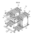
- this vaporizer is provided with a plurality of vaporizing tube blocks 102, a dispensing tube 104 that dispenses a low-temperature liquefied gas to each of the vaporizing tube blocks 102, and a collecting tube 106 that collects liquefied gas that has vaporized in each of the vaporizing tube blocks 102.
- the dispensing tube 104 refers to a site where the vaporizing tube blocks 102 are connected to each other in a piping that supplies LNG sent from a supply pump to each of the vaporizing tube blocks 102.
- the dispensing tube 104 is a site extending from a location where it branches from a main tube (not shown) to each of the vaporizing tube blocks 102.
- the dispensing tube is composed of connecting tubes 104c connected from the main tube to each of the vaporizing tube blocks 102, and a site of main tube (portion of the main tube) 104b that communicates the connecting tubes 104c.
- the collecting tube 106 refers to a site that communicates the vaporizing tube blocks 102 to each other in a piping that sends out low-temperature liquefied gas vaporized in each of the vaporizing tube blocks 102 to a consumption site and the like.
- the collecting tube 106 is a site extending from the location of merging of each of the vaporizing tube blocks 102 to the main tube.
- the collecting tube is composed of connecting tubes 106c connected from each of the vaporizing tube blocks 102 to the main tube, and a site of the main tube (portion of the main tube) 106b that communicates the connecting tubes 106c.
- each of the vaporizing tube blocks 102 has a plurality of vaporizing tube panels 108, supply side manifolds 110 that dispense low-temperature liquefied gas from the dispensing tube 104 to each of the vaporizing tube panels 108, and delivery side manifolds 112 that collect liquefied gas vaporized in each of the vaporizing tube panels 108 and send it out to the collecting tube 106.
- the plurality of vaporizing tube panels 108 are arranged in a direction perpendicular to the panel surfaces in a mutually parallel alignment.
- Each of the supply side manifolds 110 is respectively connected to the dispensing tube 104, and each of the delivery side manifolds 112 is respectively connected to the collecting tube 106.
- the vaporizing tube panels 108 have a plurality of vaporizing tubes (heat transfer tubes) 114 arranged in a specific vertical plane in a mutually parallel alignment, supply side headers 116 that dispense low-temperature liquefied gas from the supply side manifolds 110 to each of the vaporizing tubes 114, and delivery side headers 118 that collect liquefied gas vaporized in each of the vaporizing tubes 114 and send it out to the delivery side manifolds 112.
- the supply side headers 116 are connected to the lower end of each of the vaporizing tubes 114 contained in a common vaporizing panel 108 and to the supply side manifolds 110.
- the delivery side headers 118 are connected to the upper end of each of the vaporizing tubes 114 contained in a common vaporizing tube panel 108 and to the delivery side manifolds 112.
- low-temperature liquefied gas is vaporized by heat exchange between low-temperature liquefied gas flowing through the vaporizing tubes 114 and seawater flowing down over the surface of each of the vaporizing tube panels 108. More specifically, low-temperature liquefied gas supplied to the dispensing tube 104 is dispensed to each of the vaporizing tube blocks 102 by the dispensing tube 104, and is supplied from the lower end of each of the vaporizing tubes 114 into the vaporizing tubes 114 by passing through the supply side manifolds 110 and the supply side headers 116. This low-temperature liquefied gas flows through the vaporizing tubes 114 from the lower end to the upper end of the vaporizing tubes 114.
- the low-temperature liquefied gas is vaporized by exchanging, by means of those tube walls, heat with seawater that has flown down along the outer peripheral surfaces of the tube walls of the vaporizing tubes 114.
- Liquefied gas that has been vaporized in each of the vaporizing tubes 114 is collected in the collecting tube 106 after passing through the delivery side headers 118 and the delivery side manifolds 112, after which it is sent out to consumption sites and the like by passing through a piping system (not shown) connected to the collecting tube 106.
- vaporizer 100 there are cases in which vibrations occur in the vaporizer 100 and the piping system connected to the vaporizer 100 depending on operating conditions such as the pressure within each of the vaporizing tubes 114 or the flow rate or temperature of the low-temperature liquefied gas flowing the vaporizing tubes 114. These vibrations generate high stress and cause metal fatigue and the like to accumulate in each site that composes the vaporizer 100, thereby having the risk of causing damage or malfunctions.
- An object of the present invention is to provide a vaporizer for low-temperature liquefied gas capable of effectively suppressing the propagation of vibrations generated in each of the vaporizing tubes thereof caused by vaporization of low-temperature liquefied gas without causing an accompanying increase in thermal stress.
- thermohydraulic destabilizing phenomenon occurs during the course of vaporization of low-temperature liquefied gas, and that there are cases in which this causes the generation of vibrations in the vaporizer and the like.
- the present invention is provided with: a plurality of vaporizing tube blocks, each having a plurality of vaporizing tube panels in which a plurality of vaporizing tubes for vaporizing a low-temperature liquefied gas flowing therethrough by exchanging heat with the outside is arranged in a vertical plane, each of the vaporizing tube panels being arranged in a direction perpendicular to the vertical plane; an inter-block dispensing tube that is connected to each of the vaporizing tube blocks and dispenses the low-temperature liquefied gas to each of the vaporizing tube blocks; an inter-block collecting tube that is connected to each of the vaporizing tube blocks and collects and sends out the low-temperature liquefied gas vaporized in the vaporizing tube block; and an inter-block pulsation suppression unit that suppresses propagation of pressure pulsation between vaporizing tube blocks mutually connected by the inter-block dispensing tube and the inter-block collecting tube.
- the inter-block dispensing tube is a site that communicates the vaporizing tube blocks in a piping through which low-temperature liquefied gas is supplied from a supply source.
- the inter-block dispensing tube is a site extending from the location of branching from the main tube to each of the vaporizing tube blocks.
- the inter-block dispensing tube is composed of connecting tubes connected to each of the vaporizing tube blocks by being branched from the main tube and the site of the main tube that communicates these connecting tubes to each other.
- the inter-block collecting tube is a site that communicates the vaporizing tube blocks to each other in a piping that sends out the low-temperature liquefied gas vaporized in each of the vaporizing tube blocks to a consumption site and the like.
- the inter-block collecting tube is a site extending from the location of branching from the main tube to each of the vaporizing tube blocks.
- the inter-block collecting tube is composed of connecting tubes connected to the main tube from each of the vaporizing tube blocks and a site of the main tube that communicates these connecting tubes.
- a vaporizer for low-temperature liquefied gas according to the present embodiment is a so-called open rack vaporizer (ORV) that vaporizes low-temperature liquefied gas by exchanging heat between the supplied low-temperature liquefied gas and external seawater.
- ORV open rack vaporizer
- LNG liquefied natural gas
- the vaporizer is provided with a plurality (two in the present embodiment) of vaporizing tube blocks 11, a dispensing tube (inter-block dispensing tube) 12 that dispenses LNG to each of the vaporizing tube blocks 11, supply side inter-block diaphragms 13, a collecting tube (inter-block collecting tube) 14 that collects natural gas (NG) in the form of vaporized LNG that has been vaporized in each of the vaporizing tube blocks 11, delivery side inter-block diaphragms 15, and a seawater supply unit 30 that supplies seawater so as to allow the seawater to flow down along the surfaces of each of the vaporizing tube panels 16.
- NG natural gas
- Each of the vaporizing tube blocks 11 respectively has a plurality (five in the present embodiment) of vaporizing tube panels 16, a supply side manifold (inter-panel dispensing tube) 17 that dispenses LNG from the dispensing tube 12 to each of the vaporizing tube panels 16, supply side inter-panel diaphragms 18, a delivery side manifold (inter-panel dispensing tube) 19 that collects LNG vaporized in each of the vaporizing tube panels 16 (namely, NG) and sends it out to the a collecting tube 14, and delivery side inter-panel diaphragms 20.
- the surface of each of the vaporizing tube blocks 11 composed in this manner is spray coated to prevent corrosion caused by contact with seawater.
- the number of vaporizing tube panels 16 contained in a single vaporizing tube block 11 is not limited to five, but rather may also be another number.
- Each of the vaporizing tube panels 16 respectively has a plurality (90 in the present embodiment) of vaporizing tubes (heat transfer tubes) 21 arranged in a vertical plane in a mutually parallel alignment, a supply side header 22 that dispenses LNG from the supply side manifold 17 to each of the vaporizing tubes 21, a plurality of supply side inter-vaporizing tube diaphragms 23 respectively connected to the ends of each of the vaporizing tubes 21 on the side of the supply side header 22, a delivery side header 24 that collects LNG vaporized in each of the vaporizing tubes 21 and sends it out to the delivery side manifold 19, and a plurality of delivery side inter-vaporizing tube diaphragms 25 respectively connected to the ends of each of the vaporizing tubes 21 on the side of the delivery side header 24.
- the number of vaporizing tubes contained in a single vaporizing tube panel 16 is not limited to 90, but rather may also be another number.
- Each of the vaporizing tubes 21 is formed from a metal material having high thermal conductivity such as aluminum or aluminum alloy, and extends in the vertical direction.
- the supply side header 22 is a tube that extends in the horizontal direction along the above-mentioned vertical plane in which the vaporizing tubes 21 are arranged. This supply side header 22 connects the lower end of each vaporizing tube 21 contained in a common vaporizing tube panel 16 with the supply side manifold 17.
- the supply side inter-vaporizing tube diaphragms (inter-vaporizing tube pulsation suppression units provided on the LNG supply side with respect to the vaporizing tubes 21) 23 are respectively provided at each connection of the supply side header 22 to the vaporizing tubes 21.
- the supply side inter-vaporizing tube diaphragms 23 suppress the propagation of pressure pulsation between the vaporizing tubes 21 on the supply side of LNG with respect to the vaporizing tubes 21 (namely, the upstream side of the flow of LNG in the vaporizer 10). More specifically, the inside of each vaporizing tube 21 is communicated with the inside of the supply side header 22 via each of the supply side inter-vaporizing tube diaphragms 23. Each of the supply side inter-vaporizing tube diaphragms 23 suppresses the mutual propagation of pressure pulsation between the vaporizing tubes 21 that propagates through the LNG in the tubes.
- the supply side inter-vaporizing tube diaphragms 23 locally reduce the cross-sectional area of the flow path of LNG in the supply side header 22 and the vaporizing tubes 21 (to also be simply referred to as the "flow path cross-sectional area"). As a result of this local reduction in flow path cross-sectional area, pressure pulsation that passes through the supply side inter-vaporizing tube diaphragms 23 decreases due to attenuation effects based on a pressure loss of the LNG when passing through the supply side inter-vaporizing tube diaphragms 23.
- the supply side inter-vaporizing tube diaphragms 23 of the present embodiment are orifices.
- the delivery side header 24 is a tube that extends parallel to the supply side header 22. This delivery side header 24 connects the upper end of each of the vaporizing tubes 21 contained in a common vaporizing tube panel 16 with the delivery side manifold 19.
- the delivery side inter-vaporizing tube diaphragms (inter-vaporizing tube pulsation suppression units provided on the delivery side of NG (vaporized LNG) with respect to the vaporizing tubes 21) 25 are respectively provided at each connection of the delivery side header 24 to the vaporizing tubes 21.
- the delivery side inter-vaporizing tube diaphragms 25 suppress the propagation of pressure pulsation between the vaporizing tubes 21 on the delivery side of LNG with respect to the vaporizing tubes 21 (namely, the downstream side of the flow of NG in the vaporizer 10). More specifically, the inside of each vaporizing tube 21 is communicated with the inside of the delivery side header 24 via each of the delivery side inter-vaporizing tube diaphragms 25. Each of the delivery side inter-vaporizing tube diaphragms 25 suppresses the mutual propagation of pressure pulsation between the vaporizing tubes 21 that propagates through the NG in the tubes.
- the delivery side inter-vaporizing tube diaphragms 25 locally reduce the flow path cross-sectional area of NG in the delivery side header 24 and the vaporizing tubes 21. As a result of this local reduction in flow path cross-sectional area, pressure pulsation that passes through the delivery side inter-vaporizing tube diaphragms 25 decreases due to attenuation effects based on a pressure loss of the NG when passing through the delivery side inter-vaporizing tube diaphragms 25 in the same manner as the supply side inter-vaporizing tube diaphragms 23.
- the delivery side inter-vaporizing tube diaphragms 25 of the present embodiment are orifices.
- cross-sectional area of the flow path (flow path cross-sectional area) of NG within the delivery side inter-vaporizing tube diaphragms 25 is larger than the cross-sectional area of the flow path (flow path cross-sectional area) of LNG within the supply side inter-vaporizing tube diaphragms 23.
- the plurality of vaporizing tube panels 16 composed in this manner are arranged in a direction (right-left direction in Fig. 1 ) perpendicular to the panel surfaces (the above-mentioned specific vertical plane in which the vaporizing tubes 21 are arranged) in a mutually parallel alignment.
- the supply side manifold 17 is a tube that extends in a direction that intersects with the supply side headers 22 (roughly perpendicular direction in the present embodiment: direction perpendicular to the page in Fig. 2 ), and connects each supply side header 22 contained in a common vaporizing tube block 11 with the dispensing tube 12.
- the supply side inter-panel diaphragms (inter-panel pulsation suppression units provided on the supply side of LNG with respect to the vaporizing tube panels 16) 18 are respectively provided at each connection with the supply side headers 22 in the supply side manifold 17.
- the supply side inter-panel diaphragms 18 suppress the propagation of pressure pulsation between the vaporizing tube panels 16 on the supply side of LNG with respect to the vaporizing tube panels 16. More specifically, the inside of each vaporizing tube panel 16 is communicated with the inside of the supply side manifold 17 via each of the supply side inter-panel diaphragms 18. Each of the supply side inter-panel diaphragms 18 suppresses the mutual propagation of pressure pulsation between the vaporizing tube panels 16 that propagates through the LNG in the tubes.
- the supply side inter-panel diaphragms 18 locally reduce the cross-sectional area of the flow path of LNG in the supply side manifold 17 and the supply side headers 22.
- the supply side inter-panel diaphragms 18 of the present embodiment are orifices.
- the delivery side manifold 19 is a tube that extends in a direction that intersects with the delivery side headers 24 (roughly perpendicular direction in the present embodiment: direction perpendicular to the page in Fig. 2 ), and is connected to each delivery side header 24 contained in a common vaporizing tube block 11 and to the collecting tube 14.
- the delivery side inter-panel diaphragms inter-panel pulsation suppression units provided on the delivery side of NG (vaporized LNG) with respect to the vaporizing tube panels 16) 20 are respectively provided at each connection with the delivery side headers 24 in the delivery side manifold 19.
- the delivery side inter-panel diaphragms 20 suppress the propagation of pressure pulsation between the vaporizing tube panels 16 on the delivery side of NG with respect to the vaporizing tube panels 16. More specifically, the inside of each vaporizing tube panel 16 is communicated with the inside of the delivery side manifold 19 via each of the delivery side inter-panel diaphragms 20. Each of the delivery side inter-panel diaphragms 20 suppresses the mutual propagation of pressure pulsation between the vaporizing tube panels 16 that propagates through the NG in the tubes. The delivery side inter-panel diaphragms 20 locally reduce the flow path cross-sectional area of NG in the delivery side manifold 19 and the delivery side headers 24.
- the delivery side inter-panel diaphragms 20 of the present embodiment are orifices.
- the cross-sectional area of the flow path (flow path cross-sectional area) of NG within the delivery side inter-panel diaphragms 20 is larger than the cross-sectional area of the flow path (flow path cross-sectional area) of LNG within the supply side inter-panel diaphragms 18.
- the dispensing tube 12 is a tube that extends roughly parallel to the supply side manifolds 17, and is connected to each of the supply side manifolds 17.
- a supply side connection 12a is provided in the dispensing tube 12 that connects a pipe P1 for supplying LNG to the vaporizer 10 from the outside.
- Supply side inter-block diaphragms (inter-block pulsation suppression units provided on the supply side of LNG with respect to the vaporizing tube blocks 11) 13 are respectively provided at each of the connections of the dispensing tube 12 with the supply side manifolds 17.
- the dispensing tube 12 is a site that communicates the vaporizing tube blocks 11 to each other in a pipe by which LNG is supplied from a supply source such as a supply pump.
- a dispensing tube 12 of the present embodiment is composed of a pipe for dispensing LNG supplied from the pipe P1 to each of the supply side manifolds 17, it is not limited thereto.
- a dispensing tube may be composed of connecting tubes that branch from the pipe P1 and are connected to each of the supply side manifolds 17 and a site of the pipe P1 that connects these connecting pipes. Namely, this dispensing tube may be composed such that LNG is dispensed (supplied) directly to the supply side manifolds 17 from the pipe P1.
- the supply side inter-block diaphragms 13 suppress the propagation of pressure pulsation between the vaporizing tube blocks 11 on the supply side of LNG with respect to the vaporizing tube blocks 11. More specifically, the inside of each vaporizing tube block 11 is communicated with the inside of the dispensing tube 12 via each of the supply side inter-block diaphragms 13. Each of the supply side inter-block diaphragms 13 suppresses the mutual propagation of pressure pulsation between the vaporizing tube blocks 11 that propagates through the LNG in the tubes.
- the supply side inter-block diaphragms 13 locally reduce the flow path cross-sectional area of LNG in the dispensing tube 12 and the supply side manifolds 17.
- the supply side inter-block diaphragms 13 of the present embodiment are orifices.
- the collecting tube 14 is a tube that extends roughly parallel to the delivery side manifolds 19, and is connected to each of the delivery side manifolds 19.
- a delivery side connection 14a is provided in the collecting tube 14 that connects a pipe P2 for sending out NG to the outside such as a consumption site.
- Delivery side inter-block diaphragms inter-block pulsation suppression units provided on the delivery side of NG (vaporized LNG) with respect to the vaporizing tube blocks 11) 15 are respectively provided at each of the connections of the collecting tube 14 with the delivery side manifolds 19.
- the collecting tube 14 is a site that communicates the vaporizing tube blocks 11 to each other in a pipe that sends out LNG vaporized in each of the vaporizing tube blocks 11 to a consumption site and the like.
- the collecting tube 14 of the present embodiment is composed of a pipe that collects NG from each of the delivery side manifolds 19 and sends it out to the pipe P2, it is not limited thereto.
- a collecting tube may be composed of connecting tubes that branch from the pipe P2 and are connected to each of the delivery side manifolds 19 and a site of the pipe P2 that communicates these connecting pipes to each other. Namely, this collecting tube may be composed such that NG is sent out directly to the pipe P2 from each of the delivery side manifolds 19.
- the delivery side inter-block diaphragms 15 suppress the propagation of pressure pulsation between the vaporizing tube blocks 11 on the delivery side of NG with respect to the vaporizing tube blocks 11. More specifically, the inside of each vaporizing tube block 11 is communicated with the inside of the collecting tube 14 via each of the delivery side inter-block diaphragms 15. Each of the delivery side inter-block diaphragms 15 suppresses the mutual propagation of pressure pulsation between the vaporizing tube blocks 11 that propagates through the NG in the tubes.
- the delivery side inter-block diaphragms 15 locally reduce the flow path cross-sectional area of NG in the collecting tube 14 and the delivery side manifolds 19.
- the delivery side inter-block diaphragms 15 of the present embodiment are orifices.
- the cross-sectional area of the flow path (flow path cross-sectional area) of NG within the delivery side inter-block diaphragms 15 is larger than the cross-sectional area of the flow path (flow path cross-sectional area) of LNG within the supply side inter-block diaphragms 13.
- a seawater supply unit 30 is provided with a trough 31 arranged in the vicinity of the upper ends of each of the vaporizing tube panels 16, a seawater header 32 that supplies seawater to each trough 31, and a seawater manifold 33 that dispenses seawater to each seawater header 32.
- the trough 31 dispenses seawater to the upper end of each vaporizing tube panel 16 so that the seawater flows down along the surfaces of the vaporizing tube panels 16 (and more precisely, each of the vaporizing tubes 21 that compose the panels 16).
- Seawater supplied from this trough 31 that flows down the surfaces of the vaporizing tube panels 16 and LNG flowing within each of the vaporizing tubes 21 exchange heat through the tube walls of the vaporizing tubes 21 resulting in vaporization of LNG into NG.
- the vaporizer 10 configured in this manner vaporizes LNG in the manner described below.
- Seawater is supplied to the surfaces of each of the vaporizing tube panels 16 from the trough 31.
- LNG is supplied from a supply pump and the like to the dispensing tube 12 through the pipe P1 connected at the supply side connection 12a.
- the dispensing tube 12 dispenses LNG supplied by a supply pump and the like to each of the supply side manifolds 17 connected to the dispensing tube 12, and each of the supply side manifolds 17 dispenses LNG from the dispensing tube 12 to each of the supply side headers 22 connected to the supply side manifolds 17.
- Each of the supply side headers 22 dispenses the supplied LNG to each of the vaporizing tubes 21 connected to the supply side headers 22.
- LNG supplied from the supply side headers 22 flows therethrough from the lower end to the upper end thereof.
- LNG flowing through the vaporizing tubes 21 exchanges heat with seawater flowing downward along the surfaces of the vaporizing tubes 21 through the tube walls of the vaporizing tubes 21.
- LNG is vaporized to NG as a result of this heat exchange.
- LNG vaporized in each of the vaporizing tubes 21 in this manner is then collected by the delivery side headers 24, and is sent out to the delivery side manifolds 19.
- the NG sent to the delivery side manifolds 19 then passes through the collecting tube 14 and is sent out to a consumption site and the like through the pipe P2 connected at the delivery side connection 14a.
- the vaporizer 10 of the present embodiment there are cases in which LNG is vaporized at a high-pressure state in which internal pressure of each of the vaporizing tubes 21 is 70 bar to 80 bar.
- a high-pressure state if the flow volume of LNG flowing through the vaporizer 10 is low, a thermohydraulic destabilizing phenomenon occurs during the course of LNG vaporization, causing the occurrence of pressure pulsation in each of the vaporizing tubes 21.
- Pressure pulsation that has occurred in each of the vaporizing tubes 21 interacts while propagating through the LNG (or NG), eventually expanding throughout the vaporizing tube blocks 11, and resulting in the generation of pressure pulsation in the individual vaporizing tube panels 16 and vaporizing tube blocks 11.
- pressure pulsation propagates between the vaporizing tube panels via the supply side manifolds or delivery side manifolds while in this state of increased amplitude, the pressure pulsation in each of the vaporizing tube panels interacts resulting in an increase in amplitude thereof. If the amplitude of that pressure pulsation increases in each of the vaporizing tube panels, the amplitude of pressure pulsation also increases in the individual vaporizing tube blocks composed by these vaporizing tube panels. Pressure pulsation is then propagated in the vaporizing tube blocks via the dispensing tube or collecting tube while in this state of increased amplitude, and the pressure pulsation that has been generated in each of the vaporizing tube panels interacts. As a result, the pressure pulsation having increased amplitude generates an exciting force in the form of vibrations in the vaporizer and piping system connected thereto.
- vibrations attributable to the flow of LNG (or NG) through the piping is effectively suppressed by each of the supply side inter-block diaphragms 13, delivery side inter-block diaphragms 15, the supply side inter-panel diaphragms 18, the delivery side inter-panel diaphragms 20, the supply side inter-vaporizing tube diaphragms 23 and the delivery side inter-vaporizing tube diaphragms 25.
- the propagation of pressure pulsation between the vaporizing tube blocks 11 is effectively suppressed by the supply side inter-block diaphragms 13 and the delivery side inter-block diaphragms 15, and as a result thereof, increases in the amplitude of pressure pulsation occurring in the individual vaporizing tube blocks 11 that have a considerable effect on vibration of the vaporizer 10 and the like can be suppressed.
- the supply side inter-vaporizing tube diaphragms 23 and the delivery side inter-vaporizing tube diaphragms 25 suppress increases in the amplitude of pressure pulsation occurring in the individual vaporizing tubes 21.
- the supply side inter-vaporizing tube diaphragms 23 and the delivery side inter-vaporizing tube diaphragms 25 suppress the amplitude of pressure pulsation in the individual vaporizing tube panels 16 and the individual vaporizing tube blocks 11 caused by pressure pulsation that has propagated from the vaporizing tubes 21.
- each of the diaphragms 13, 15, 18 and 20 respectively suppress increases in amplitude caused by interaction of pressure pulsation in the individual vaporizing tube panels 16 as well as increases in amplitude caused by interaction of pressure pulsation in the individual vaporizing tube blocks 11.
- the collecting tube 14 each of the manifolds 17 and 19 and each of the headers 22 and 24 suppress vibrations attributable to the flow of LNG or NG in the piping, it is not necessary to specially enhance the rigidity of the entire vaporizer 10 to suppress those vibrations. Accordingly, increases in thermal stress in the vaporizer 10 caused by increased rigidity can also be avoided.
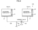
- a vaporizer 10A is provided with a plurality of the vaporizing tube blocks 11 (two vaporizing tube blocks 11A and 11B in the present embodiment) and a dispensing tube 12A.
- this vaporizer 10A differs from the vaporizer 10 of the first embodiment in that is it not provided with the supply side inter-block diaphragms 13, the delivery side inter-block diaphragms 15, the supply side inter-panel diaphragms 18, the delivery side inter-panel diaphragms 20, the supply side inter-vaporizing tube diaphragms 23 or the delivery side inter-vaporizing tube diaphragms 25.
- An inter-block pulsation suppression unit in the form of a variable valve 40 is provided in the dispensing tube 12A.
- This variable valve 40 is provided in the flow path of LNG to a specific vaporizing tube block 11A in the dispensing tube 12A. More specifically, the variable valve 40 is provided between a supply side connection 12a in the dispensing tube 12A and the supply side manifold 17 of the specific vaporizing tube block 11A (vaporizing tube block on the left side of Fig. 4 ), and is able to change the cross-sectional area of the flow path (flow path cross-sectional area) of the site where the variable valve 40 is provided.
- variable valve 40 is able to locally reduce the cross-sectional area of the flow path (flow path cross-sectional area) formed from the supply side connection 12a to the specific vaporizing tube block 11A in the dispensing tube 12A by being operated so as to narrow the flow path.
- variable valve 40 is operated based on the flow volume of LNG supplied to the vaporizer 10A from a supply pump and the like. More specifically, the variable valve 40 is reduced in opening area when the flow volume of LNG supplied to the vaporizer 10A is small. As a result, the cross-sectional area of the flow path (flow path cross-sectional area) in the dispensing tube 12A that connects the vaporizing tube blocks 11 is locally reduced. This is because there is increased susceptibility to the occurrence of a thermohydraulic destabilizing phenomenon in the vaporizing tubes 21 when the flow volume of LNG to the vaporizing tubes 21 in a high-pressure state is small.
- variable valve 40 is reduced in opening area when the flow volume of LNG supplied to the vaporizer 10A is small.
- the variable valve 40 effectively suppresses the propagation of pressure pulsation between the vaporizing tube blocks 11 by locally reducing the cross-sectional area of the flow path within the dispensing tube 12A.
- the variable valve 40 suppresses increases in amplitude of pressure pulsation occurring in the individual vaporizing tube blocks 11 that have a considerable effect on vibration of the vaporizer 10A and the like. In this manner, vibrations occurring attributable to vaporization of LNG can be effectively suppressed in the vaporizer 10A.
- variable valve 40 provided in the dispensing tube 12A suppresses vibrations attributable to the flow of LNG through the piping, it is not necessary to specially enhance the rigidity of the entire vaporizer 10A in order to suppress those vibrations. Accordingly, increases in thermal stress in the vaporizer caused by increased rigidity can also be avoided.
- the degree of this reduction in thickness of the spray coating varies according operating conditions such as the flow rate of LNG (NG) flowing through the vaporizing tubes 21 or the surface temperature thereof. Consequently, if LNG is supplied to only one of the vaporizing tube blocks 11, the service life of the spray coating becomes shorter for that single vaporizing tube block 11 only. Therefore, the temperature difference between both blocks 11 can be inhibited by supplying LNG to both of the vaporizing tube blocks 11 even when the flow volume of LNG supplied to the vaporizer 10A is small, thereby making it possible to suppress the difference in service life of the spray coating carried out on the surfaces of each of the vaporizing tube blocks 11. As a result, recoating work based on the service life of the spray coating can be carried out simultaneously on both of the blocks 11.
- NG flow rate of LNG
- variable valve 40 is opened when the flow volume of LNG supplied to the vaporizer 10A is large, and is operated so as to increase the flow path cross-sectional area in the variable valve 40. This is because there is less likelihood of the generation of pressure pulsation in the piping of the vaporizer 10A (such as the vaporizing tubes 21, the headers 22 and 24, the manifolds 17 and 29, the dispensing tube 12A or the collecting tube 14) when the flow volume of LNG supplied to the vaporizer 10A is large.
- variable valve 40 By opening the variable valve 40 in the manner described above at this time, in addition to pressure loss within the dispensing tube 12A being reduced, the flow volume of LNG supplied to a specific vaporizing tube block 11 increases, thereby improving vaporization efficiency of the vaporizer 10A as a result thereof.
- Control of opening and closing of the variable valve 40 based on the flow volume of LNG as described above may be carried out manually or may be carried out automatically by a controller and the like based on the flow volume of LNG supplied to the vaporizer 10A.
- variable valve 40 may not only be provided between the supply side connection 12a of the dispensing tube 12A and the supply side manifold 17 of the specific vaporizing tube block 11A, but may also be respectively provided between the supply side connection 12a and the supply side manifold 17 of each of the vaporizing tube blocks 11A and 11B.
- the variable valve 40 may also be provided in the collecting tube 14 (see Fig. 1 ).
- the variable valve 40 may be provided between the delivery side connection 14a and the delivery side manifold 19 of the specific vaporizing tube block 11A, or may be respectively provided between the delivery side connection 14a and the delivery side manifold 19 of each of the vaporizing tube blocks 11 A and 11B.
- the dispensing tube 12A in the present embodiment is configured with a tube that dispenses LNG supplied from the pipe (main pipe) P1 to each of the vaporizing tube blocks 11, as shown in Figs. 5A and 5B , for example, the dispensing tube 12A may also be configured so that LNG is supplied directly from the pipe P1 to each of the vaporizing tube blocks 11.
- the dispensing tube 12A may be configured with connecting tubes C 1 and C2 branched from the pipe P1 and a site of the pipe P1 that connects these connecting tubes C 1 and C2.
- variable valve 40 may be respectively provided in each of the connecting tubes C1 and C2, or may only be provided in one of the connecting tubes C1 (or C2). In addition, the variable valve 40 may also be provided between the upstream side connecting tube C 1 and the downstream side connecting tube C2 in the pipe P1 (see Fig. 5B ).
- the collecting tube 14 may also be configured with connecting tubes branched from the pipe P2 and connected to each of the vaporizing tube blocks 11 and a site of the pipe P2 that connects these connecting tubes. In this case as well, the variable valve 40 may be respectively provided in each of the connecting tubes, or may only be provided in one of the connecting tubes. In addition, the variable valve 40 may also be provided between the upstream side connecting tube and the downstream side connecting tube in the pipe P2.
- a vaporizer 10B according to the present embodiment is provided with a dispensing tube 12B.
- An inter-block pulsation suppression unit in the form of an on-off valve (on-off member) 41 and a bypass tube 42 are provided in this dispending tube 12B.
- the on-off valve 41 is provided in the flow path of LNG to the specific vaporizing tube block 11A (the vaporizing tube block on the right side in Fig. 6A ) in the dispensing tube 12B. More specifically, the on-off valve 41 is provided between the supply side connection 12a in the dispensing tube 12B and the supply side manifold 17 of the specific vaporizing tube block 11A, and opens and closes the flow path at the site where the on-off valve 41 is provided.
- the bypass tube 42 forms a flow path that branches from the dispensing tube 12B upstream from the on-off valve 41 and allows LNG to flow into the above-mentioned specific vaporizing tube block 11A while bypassing the on-off valve 41.
- the bypass tube 42 of the present embodiment branches from the dispensing tube 12B upstream from the on-off valve 41, and is connected to the dispensing tube 12B downstream from the on-off valve 41 after having bypassed the on-off valve 41.
- the bypass tube 42 may also branch from the dispensing tube 12B upstream from the on-off valve 41 and be connected directly to the vaporizing tube block 11A downstream from the on-off valve 41 (and more precisely, to the supply side manifold 17).
- the bypass tube 42 has a diaphragm (bypass diaphragm) 43.
- This diaphragm 43 locally reduces the cross-sectional area of the flow path (flow path cross-sectional area) formed in the bypass tube 42.
- the diaphragm 43 of the present embodiment is an orifice.
- the on-off valve 41 is operated based on the flow volume of LNG supplied to the vaporizer 10B from a supply pump and the like. More specifically, the on-off valve 41 is closed when the flow volume of LNG supplied to the vaporizer 10B is small. As a result, LNG is allowed to be supplied to the specific vaporizing tube block 11A through the bypass tube 42. As a result, the specific vaporizing tube block 11A and the other vaporizing tube block 11B are mutually communicated only through the bypass tube 42 in which the cross-sectional area of the flow path formed therein has been locally reduced by the diaphragm 43.
- vibrations occurring attributable to vaporizing of LNG can be effectively suppressed in the vaporizer 10B.
- vibrations attributable to the flow of LNG through the piping are suppressed by the on-off valve 41 and the bypass tube 42, it is not necessary to enhance rigidity of the entire vaporizer 10B in order to suppress vibrations, and there is also no occurrence of increases in thermal stress in the vaporizer 10B attributable thereto.
- the on-off valve 41 is opened when the flow volume of LNG supplied to the vaporizer 10B is large since there is less likelihood of the generation of pressure pulsation in the piping of the vaporizer 10B (such as the vaporizing tubes 21, the headers 22 and 24, the manifolds 17 and 29, the dispensing tube 12B and the collecting tube 14).
- the flow volume of LNG supplied to a specific vaporizing tube block 11 A increases, thereby improving vaporization efficiency of the vaporizer 10B.
- Control of opening and closing of the on-off valve 41 based on the flow volume of LNG as described above may be carried out manually or may be carried out automatically by a controller and the like based on the flow volume of the supplied LNG.
- the dispensing tube 12B in the present embodiment is configured with a tube that dispenses LNG supplied from the pipe P1 to each of the vaporizing tube blocks 11, as shown in Fig. 6B , for example, the dispensing tube 12B may also be configured with the connecting tubes C 1 and C2 branched from the pipe P1 and a site of the pipe P1 that connects these connecting tubes C1 and C2.
- the bypass tube 42 may be arranged so as to mutually connect the upstream connecting tube C 1 and the downstream connecting tube C2, and the on-off valve 41 may be provided upstream from the connection between the connecting tube C2 and the bypass tube 42 in the downstream connecting tube C2.
- the on-off valve 41 and the bypass tube 42 may also be respectively provided between the supply side connection 12a of the dispensing tube 12B and each of the vaporizing tube blocks 11A and 11 B in the manner of a vaporizer 10C shown in Fig. 7A .
- the on-off valve 41 may be respectively provided in each of the connecting tubes C1 and C2
- the bypass tube 42 may be respectively provided between the pipe P1 and each of the vaporizing tube blocks 11 as shown in Fig. 7B .
- the on-off valve 41 and the bypass tube 42 may also be provided in the collecting tube 14 (see Fig. 1 ).
- the on-off valve 41 and the bypass tube 42 may be provided between the delivery side connection 14a and the specific vaporizing tube block 11A, or may be respectively provided between the delivery side connection 14a and each of the vaporizing tube blocks 11A and 11B.
- the collecting tube 14 is composed of connecting tubes branched from the pipe P2 and connected to each of the vaporizing tube blocks 11 and a site of the pipe P2 that connects these connecting tubes
- the on-off valve 41 may be respectively provided in each of the connecting tubes
- the bypass tube 42 may be respectively provided between the pipe P2 and each of the vaporizing tube blocks 11.
- a vaporizer 10D according to the present embodiment is provided with a dispensing tube 12D and an interconnecting tube 44.
- This dispensing tube 12D has an on-off valve (on-off member) 45.
- This on-off valve 45 composes an inter-block pulsation suppression unit in the vaporizer 10D together with the interconnecting tube 44.
- the on-off valve 45 is provided in the flow path of LNG to the specific vaporizing tube block 11A in the dispensing tube 12B. More specifically, the on-off valve 45 is provided in the dispensing tube 12D between the supply side connection 12a and the supply side manifold 17 of the specific vaporizing tube block 11A, and opens and closes the flow path at the site where the on-off valve 41 is provided.
- the interconnecting tube 44 connects the specific vaporizing tube block 11A with the other vaporizing tube block 11B. More specifically, the interconnecting tube 44 connects the supply side manifold 17 of the specific vaporizing tube block 11A with the supply side manifold 17 of the other vaporizing tube block 11B, and as a result thereof, the supply sides of both of the blocks 11A and 11B are mutually communicated.
- the above-mentioned on-off valve 45 is closed while in this state, the specific vaporizing tube block 11A and the other vaporizing tube block 11B are only communicated by the interconnecting tube 44.
- a diaphragm (interconnecting diaphragm) 46 is provided in the interconnecting tube 44.
- the diaphragm 46 locally reduces the cross-sectional area of the flow path (flow path cross-sectional area) formed in the interconnecting tube 44.
- the diaphragm 46 of the present embodiment is an orifice.
- the on-off valve 45 is opened and closed based on the flow volume of LNG supplied to the vaporizer 10D from a supply pump and the like. More specifically, the on-off valve 45 is closed when the flow volume of LNG supplied to the vaporizer 10D is small. Whereupon, the supply of LNG from the dispensing tube 12D to the specific vaporizing tube block 11A is stopped, and LNG is essentially only supplied to the vaporizing tube block 11B from the dispensing tube 12D.
- LNG supplied to the supply side manifold 17 of this vaporizing tube block 11B is dispensed to each of the vaporizing tube panels 16 (and more precisely, each of the supply side headers 22) contained in the other vaporizing tube block 11B, and is also supplied to the specific vaporizing tube block 11A only through the interconnecting tube 44 in which the cross-sectional area of the flow path formed therein is locally reduced by the diaphragm 46.
- the on-off valve 45 is opened when the flow volume of LNG supplied to the vaporizer 10D is large. Since there is less likelihood of the generation of pressure pulsation in the piping of the vaporizer 10D (such as the vaporizing tubes 21, the headers 22 and 24, the manifolds 17 and 29, the dispensing tube 12B and the collecting tube 14) at this time, by opening the on-off valve 45 and allowing LNG to be supplied directly to the vaporizing tube block 11A from the dispensing tube 12D, pressure loss in the vaporizer 10D can be reduced, and the flow volume of LNG supplied to the specific vaporizing tube block 11A can be increased, thereby making it possible to improve vaporization efficiency of the vaporizer 10D.
- Control of opening and closing of the on-off valve 45 based on the flow volume of LNG as described above may be carried out manually or may be carried out automatically by a controller and the like based on the flow volume of the supplied LNG.
- the interconnecting tube 44 may also be provided so as to connect the delivery side manifold 19 of the other vaporizing tube block 11B (see Fig. 1 ) with the delivery side manifold 19 of the specific vaporizing tube block 11A.
- the on-off valve 45 is provided in the collecting tube 14 between the delivery side connection 14a and the specific vaporizing tube block 11A (or the other vaporizing tube block 11B).
- the on-off valve 45 and the interconnecting tube 44 are provided at such locations, by closing the on-off valve 45, the propagation of pressure pulsation between the vaporizing tube blocks 11 can be effectively suppressed in at least one of the interconnecting tube 44 that connects the supply side manifolds 17 or the interconnecting tube 44 that connects the delivery side manifolds 19.
- the vaporizer of the present invention is not limited to the above-mentioned first to fourth embodiments, but rather various modifications can naturally be added within a range that does not deviate from the gist of the present invention.
- the diaphragms 23, 25, 18, 20, 13 and 15 are provided at all connections consisting of the connections between the vaporizing tubes 21 and the headers 22 (or headers 24), the connections between the headers 22 (or the headers 24) and the manifolds 17 (or the manifolds 19), and the connections between the manifolds 17 (or the manifolds 19) and the dispensing tube 12 (or the collecting tube 14) in the first embodiment
- the arranged locations of the diaphragms are not limited thereto, but rather are at least only required to be arranged so as to be able to suppress the transmission of pressure pulsation between the vaporizing tube blocks 11, and increases in amplitude of pressure pulsation occurring in the individual vaporizing tube blocks 11 that have a considerable effect on vibration of the vaporizer 10 and the like.
- the inter-block diaphragms 13 (or 15) are at least required to be provided in the vaporizer 10.
- variable valve 40 is provided in the second embodiment is not limited to the dispensing tube 12A or the collecting tube 14.
- the variable valve 40 may also be provided between the manifolds 17 and 19 and the headers 22 and 24, or may be provided between the headers 22 and 24 and the vaporizing tubes 21.
- the vaporizer for low-temperature liquefied gas is provided with a plurality of vaporizing tube blocks each having a plurality of vaporizing tube panels in which a plurality of vaporizing tubes for vaporizing a low-temperature liquefied gas flowing therethrough by exchanging heat with the outside is arranged in a specific vertical plane, each of the vaporizing tube panels being arranged in a direction perpendicular to the vertical plane; an inter-block dispensing tube (dispensing tube) that is connected to each of the vaporizing tube blocks and dispenses the low-temperature liquefied gas to each of the vaporizing tube blocks; an inter-block collecting tube (collecting tube) that is connected to each of the vaporizing tube blocks and collects and sends out the low-temperature liquefied gas vaporized in the vaporizing tube block; and an inter-block pulsation suppression unit that suppresses propagation of pressure pulsation in vaporizing tube blocks
- the above-mentioned inter-block pulsation suppression unit may be an inter-block diaphragm provided in at least one of the above-mentioned inter-block dispensing tube and inter-block collecting tube that locally reduces a cross-sectional area of a flow path (flow path cross-sectional area) of the above-mentioned low-temperature liquefied gas within that tube.
- This inter-block diaphragm reduces pressure pulsation that passes through the diaphragm due to attenuation effects based on pressure loss of the low-temperature liquefied gas when passing through the diaphragm. Consequently, by providing this inter-block diaphragm in the inter-block dispensing tube or inter-block collecting tube, the propagation of pressure pulsation between the vaporizing tube blocks via the inter-block dispensing tube or inter-block collecting tube can be effectively suppressed.
- the vaporizer may also be provided with an inter-panel dispensing tube, which is connected to each of the vaporizing tube panels contained in a common vaporizing tube block and is connected to the above-mentioned inter-block dispensing tube, and dispenses the above-mentioned low-temperature liquefied gas from the inter-block dispensing tube to each of the above-mentioned vaporizing tube panels; an inter-panel collecting tube, which is connected to each of the vaporizing tube panels contained in the above-mentioned common vaporizing tube block and is connected to the above-mentioned inter-block collecting tube, and collects the low-temperature liquefied gas vaporized in the vaporizing tube panel and sends out the gas to the above-mentioned inter-block collecting tube; and an inter-panel pulsation suppression unit that suppresses propagation of pressure pulsation between vaporizing tube panels mutually connected by the inter-panel dispensing tube and the inter-panel collecting tube.
- the propagation of pressure pulsation that has increased in amplitude in the vaporizing tube panels and increases in amplitude of the pressure pulsation in the individual vaporizing tube blocks can be suppressed while also suppressing increases in the amplitude of pressure pulsation generated in the individual vaporizing tube blocks that have a considerable effect on vibration of the vaporizer and the like by the inter-block pulsation suppression means, thereby making it possible to more effectively suppress vibrations caused by the flow of low-temperature liquefied gas through the piping.
- the above-mentioned inter-panel pulsation suppression unit may be an inter-panel diaphragm provided in at least one of the above-mentioned inter-panel dispensing tube and inter-panel collecting tube that locally reduces a cross-sectional area of a flow path of the above-mentioned low-temperature liquefied gas within that tube.
- pressure pulsation that passes through the inter-panel diaphragm can be reduced due to attenuation effects based on pressure loss of the low-temperature liquefied gas when passing through the inter-panel diaphragm. Consequently, by providing this inter-panel diaphragm in the inter-panel dispensing tube or inter-panel collecting tube, the propagation of pressure pulsation between the vaporizing tube panels via the inter-panel dispensing tube or inter-panel collecting tube can be effectively suppressed.
- the vaporizer may also be provided with an inter-vaporizing tube dispensing tube, which is connected to each of the vaporizing tubes contained in a common vaporizing tube panel and is connected to the above-mentioned inter-panel dispensing tube, and dispenses the above-mentioned low-temperature liquefied gas from the inter-panel dispensing tube to each of the above-mentioned vaporizing tubes; an inter-vaporizing tube collecting tube, which is connected to each of the vaporizing tubes contained in the above-mentioned common vaporizing tube panel and is connected to the above-mentioned inter-panel collecting tube, and collects the low-temperature liquefied gas vaporized in the vaporizing tubes and sends out the gas to the above-mentioned inter-panel collecting tube; and an inter-vaporizing tube pulsation suppression unit that suppresses propagation of pressure pulsation between vaporizing tubes mutually connected by the above-mentioned inter-vaporizing tube dispensing tube and inter-vaporizing
- the propagation of pressure pulsation that has increased in amplitude in the vaporizing tubes and increases in amplitude of the pressure pulsation in the individual vaporizing tube panels and individual vaporizing tube blocks can be suppressed while also respectively suppressing increases in the amplitude of pressure pulsation in the individual vaporizing tube panels and increases in the amplitude of pressure pulsation in the individual vaporizing tube blocks with the inter-panel pulsation suppression unit and inter-block pulsation suppression unit, thereby making it possible to more effectively suppress vibrations caused by the flow of low-temperature liquefied gas through the piping.
- the above-mentioned inter-vaporizing tube pulsation suppression unit may be an inter-vaporizing tube diaphragm provided in at least one of the above-mentioned inter-vaporizing tube dispensing tube and inter-vaporizing tube collecting tube that locally reduces a cross-sectional area of a flow path of the above-mentioned low-temperature liquefied gas within that tube.
- pressure pulsation that passes through the inter-vaporizing tube diaphragm can be reduced due to attenuation effects based on pressure loss of the low-temperature liquefied gas when passing through the inter-vaporizing tube diaphragm. Consequently, by providing this inter-vaporizing tube diaphragm in the inter-vaporizing tube dispensing tube or inter-vaporizing tube collecting tube, the propagation of pressure pulsation between the vaporizing tubes via the inter-vaporizing tube dispensing tube or inter-vaporizing tube collecting tube can be effectively suppressed.
- the vaporizer may also be provided with inter-vaporizing tube dispensing tubes, which are connected to each of the vaporizing tubes contained in a common vaporizing tube panel, and dispense the above-mentioned low-temperature liquefied gas to each of the above-mentioned vaporizing tubes; inter-vaporizing tube collecting tubes, which are connected to each of the vaporizing tubes contained in the above-mentioned common vaporizing tube panel, and collect and send out the low-temperature liquefied gas vaporized in the vaporizing tubes; an inter-panel dispensing tube, which is connected to each of the inter-vaporizing tube dispensing tubes contained in a common vaporizing tube block and is connected to the above-mentioned inter-block dispensing tube, and dispenses low-temperature liquefied gas from the above-mentioned inter-block dispensing tube to each of the above-mentioned inter-vaporizing tube dispensing tubes; an inter-panel collecting tube, which is connected to each of the inter
- the propagation of pressure pulsation that has increased in amplitude in the vaporizing tubes and increases in amplitude of the pressure pulsation in the individual vaporizing tube panels and individual vaporizing tube blocks can be suppressed while also suppressing increases in the amplitude of pressure pulsation generated in individual vaporizing tube blocks that have a considerable effect on vibration of the vaporizer and the like by the inter-block pulsation suppression unit, thereby making it possible to more effectively suppress vibrations caused by the flow of low-temperature liquefied gas through the piping.
- the above-mentioned inter-vaporizing tube pulsation suppression unit may be an inter-vaporizing tube diaphragm which is provided in either or both of the above-mentioned inter-vaporizing tube dispensing tubes and inter-vaporizing tube collecting tubes and locally reduces a cross-sectional area of a flow path of the above-mentioned low-temperature liquefied gas within those tubes.
- pressure pulsation that passes through the inter-vaporizing tube diaphragm can be reduced due to attenuation effects based on pressure loss of the low-temperature liquefied gas when passing through the inter-vaporizing tube diaphragm. Consequently, by providing this inter-vaporizing tube diaphragm in the inter-vaporizing tube dispensing tubes or inter-vaporizing tube collecting tubes, the propagation of pressure pulsation in the vaporizing tubes via the inter-vaporizing tube dispensing tubes or inter-vaporizing tube collecting tubes can be effectively suppressed.
- the above-mentioned inter-block diaphragm may be respectively provided in the above-mentioned inter-block dispensing tube and the above-mentioned inter-block collecting tube, and a flow path cross-sectional area of the inter-block diaphragm provided in the above-mentioned inter-block collecting tube may be larger than a flow path cross-sectional area of the inter-block diaphragm provided in the above-mentioned inter-block dispensing tube.
- the above-mentioned inter-panel diaphragm may be respectively provided in the above-mentioned inter-panel dispensing tube and the above-mentioned inter-panel collecting tube, and a flow path cross-sectional area of the inter-panel diaphragm provided in the above-mentioned inter-panel collecting tube may be larger than a flow path cross-sectional area of the inter-panel diaphragm provided in the above-mentioned inter-panel dispensing tube.
- the above-mentioned inter-vaporizing tube diaphragm may be respectively provided in the above-mentioned inter-vaporizing tube dispensing tube and the above-mentioned inter-vaporizing tube collecting tube, and a flow path cross-sectional area of the inter-vaporizing tube diaphragm provided in the above-mentioned inter-vaporizing tube collecting tube may be larger than a flow path cross-sectional area of the inter-vaporizing tube diaphragm provided in the above-mentioned inter-vaporizing tube dispensing tube.
- the above-mentioned inter-block diaphragm may also be a variable valve that is able to change a flow path cross-sectional area in this inter-block diaphragm.
- the cross-sectional area of the flow path of low-temperature liquefied gas formed within the tube can be locally reduced.
- the propagation of pressure pulsation between the vaporizing tube blocks can be effectively suppressed, and increases in the amplitude thereof can be suppressed.
- there is less susceptibility to the occurrence of pressure pulsation when the flow volume of the low-temperature liquefied gas is large by making the flow path cross-sectional area in the variable valve larger than in the above-mentioned reduced in opening state, pressure loss in the variable valve can be reduced.
- the above-mentioned inter-block pulsation suppression unit may have a first on-off member, which is provided in the above-mentioned inter-block dispensing tube and opens and closes the flow path of the above-mentioned low-temperature liquefied gas to a specific vaporizing tube block in the inter-block dispensing tube; and a first bypass tube, which branches from the above-mentioned inter-block dispensing tube upstream from the first on-off member and forms a flow path that allows the above-mentioned low-temperature liquefied gas to flow into the above-mentioned specific vaporizing tube block by bypassing the first on-off member; and the above-mentioned first bypass tube may be provided with a first bypass diaphragm that locally reduces a cross-sectional area of the flow path of the above-mentioned low-temperature liquefied gas formed in the tube.
- the above-mentioned inter-block pulsation suppression unit may have a second on-off member, which is provided in the above-mentioned inter-block collecting tube and opens and closes the flow path of the above-mentioned vaporized low-temperature liquefied gas from a specific vaporizing tube block in the inter-block collecting tube; and a second bypass tube, which bypasses the above-mentioned second on-off member from the above-mentioned specific vaporizing tube block and forms a flow path of the above-mentioned vaporized low-temperature liquefied gas that merges with the above-mentioned inter-block collecting tube downstream from the second on-off member; and the above-mentioned second bypass tube may be provided with a second bypass diaphragm that locally reduces a cross-sectional area of the flow path of the above-mentioned low-temperature liquefied gas formed in the tube.
- the bypass diaphragms provided in the bypass tubes are able to effectively suppress the propagation of pressure pulsation between the vaporizing tube blocks by closing the on-off members and allowing the low-temperature liquefied gas to bypass through the bypass tubes.
- interaction of pressure pulsation occurring in each of the vaporizing tube blocks and increases in amplitude thereof can be suppressed.
- there is less susceptibility to the occurrence of pressure pulsation when the flow volume of the low-temperature liquefied gas is large by opening the on-off member and allowing the low-temperature liquefied gas to flow through the flow path that had been closed by the on-off member, pressure loss throughout the entire vaporizer can be reduced.
- Each of the vaporizing tube blocks may be provided with an inter-panel dispensing tube, which is connected to each of the vaporizing tube panels contained in the vaporizing tube block and is connected to the above-mentioned inter-block dispensing tube, and dispenses the above-mentioned low-temperature liquefied gas from the above-mentioned inter-block dispensing tube to each of the above-mentioned vaporizing tube panels;
- the above-mentioned inter-block pulsation suppression unit may have a third on-off member, which is provided in the above-mentioned inter-block dispensing tube and opens and closes the flow path of the above-mentioned low-temperature liquefied gas to a specific vaporizing tube block in the above-mentioned inter-block dispensing tube, and a supply side interconnecting tube that connects the inter-panel dispensing tube of the above-mentioned specific vaporizing tube block with the inter-panel dispensing tube of another
- each of the above-mentioned vaporizing tube blocks may be provided with an inter-panel collecting tube, which is connected to each of the vaporizing tube panels contained in the vaporizing tube block and is connected to the above-mentioned inter-block collecting tube, and collects the liquefied gas vaporized in each of the above-mentioned vaporizing tube panels and sends out the gas to the above-mentioned inter-block collecting tube;
- the above-mentioned inter-block pulsation suppression unit may have a fourth on-off member, which is provided in the above-mentioned inter-block collecting tube and opens and closes the flow path of the above-mentioned vaporized low-temperature liquefied gas from a specific vaporizing tube block in the inter-block collecting tube, and a delivery side interconnecting tube that connects the inter-panel collecting tube of the above-mentioned specific vaporizing tube block with the inter-panel collecting tube of another vaporizing tube block; and the above-mentioned delivery
- the on-off member provided in the inter-block dispensing tube is closed and the flow path that connects the inter-block dispensing tube and the specific vaporizing tube block is closed, low-temperature liquefied gas supplied to another vaporizing tube block from the inter-block dispensing tube is supplied to the specific vaporizing tube block via the supply side interconnecting tube.
- the on-off member provided in the inter-block collecting tube is closed and the flow path that connects the inter-block collecting tube and the specific vaporizing tube block is closed, the low-temperature liquefied gas vaporized in the specific vaporizing tube block is sent out to the inter-block collecting tube via the delivery side interconnecting tube and another vaporizing tube block in that order.
- the vaporizer for low-temperature liquefied gas according to the present invention is useful as a vaporizer for vaporizing a low-temperature liquefied gas such as liquefied natural gas (LNG), liquefied petroleum gas (LPG) or liquid nitrogen (LN 2 ) by exchanging heat with a heat transfer medium such as seawater, and a vaporizer for low-temperature liquefied gas can be provided that is capable of effectively suppressing the propagation of vibrations generated in each of the vaporizing tubes thereof caused by vaporization of low-temperature liquefied gas without causing an accompanying increase in thermal stress.
- LNG liquefied natural gas
- LPG liquefied petroleum gas
- LN 2 liquid nitrogen
Landscapes
- Engineering & Computer Science (AREA)
- General Engineering & Computer Science (AREA)
- Mechanical Engineering (AREA)
- Physics & Mathematics (AREA)
- Thermal Sciences (AREA)
- Filling Or Discharging Of Gas Storage Vessels (AREA)
- Pipe Accessories (AREA)
Priority Applications (1)
| Application Number | Priority Date | Filing Date | Title |
|---|---|---|---|
| EP17167335.3A EP3225901A1 (de) | 2010-06-18 | 2011-04-13 | Verdampfer für bei niedriger temperatur verflüssigtes gas |
Applications Claiming Priority (2)
| Application Number | Priority Date | Filing Date | Title |
|---|---|---|---|
| JP2010139208A JP5363427B2 (ja) | 2010-06-18 | 2010-06-18 | 低温液化ガスの気化装置 |
| PCT/JP2011/002183 WO2011158417A1 (ja) | 2010-06-18 | 2011-04-13 | 低温液化ガスの気化装置 |
Related Child Applications (2)
| Application Number | Title | Priority Date | Filing Date |
|---|---|---|---|
| EP17167335.3A Division EP3225901A1 (de) | 2010-06-18 | 2011-04-13 | Verdampfer für bei niedriger temperatur verflüssigtes gas |
| EP17167335.3A Division-Into EP3225901A1 (de) | 2010-06-18 | 2011-04-13 | Verdampfer für bei niedriger temperatur verflüssigtes gas |
Publications (3)
| Publication Number | Publication Date |
|---|---|
| EP2573449A1 true EP2573449A1 (de) | 2013-03-27 |
| EP2573449A4 EP2573449A4 (de) | 2016-11-23 |
| EP2573449B1 EP2573449B1 (de) | 2020-06-24 |
Family
ID=45347835
Family Applications (2)
| Application Number | Title | Priority Date | Filing Date |
|---|---|---|---|
| EP11795325.7A Active EP2573449B1 (de) | 2010-06-18 | 2011-04-13 | Verdampfer für bei niedriger temperatur verflüssigtes gas |
| EP17167335.3A Withdrawn EP3225901A1 (de) | 2010-06-18 | 2011-04-13 | Verdampfer für bei niedriger temperatur verflüssigtes gas |
Family Applications After (1)
| Application Number | Title | Priority Date | Filing Date |
|---|---|---|---|
| EP17167335.3A Withdrawn EP3225901A1 (de) | 2010-06-18 | 2011-04-13 | Verdampfer für bei niedriger temperatur verflüssigtes gas |
Country Status (7)
| Country | Link |
|---|---|
| EP (2) | EP2573449B1 (de) |
| JP (1) | JP5363427B2 (de) |
| KR (2) | KR101412263B1 (de) |
| CN (1) | CN102947637B (de) |
| ES (1) | ES2802625T3 (de) |
| MY (1) | MY173937A (de) |
| WO (1) | WO2011158417A1 (de) |
Cited By (2)
| Publication number | Priority date | Publication date | Assignee | Title |
|---|---|---|---|---|
| CN104565812A (zh) * | 2014-12-31 | 2015-04-29 | 无锡冠云铝业有限公司 | 天然气蒸发器 |
| EP4368934A1 (de) * | 2022-11-14 | 2024-05-15 | Doosan Enerbility Co., Ltd. | Einmaldurchlaufwärmetauscher und kombiniertes stromerzeugungssystem damit |
Families Citing this family (6)
| Publication number | Priority date | Publication date | Assignee | Title |
|---|---|---|---|---|
| JP2014202320A (ja) * | 2013-04-08 | 2014-10-27 | 株式会社神戸製鋼所 | 低温液化ガスの気化装置 |
| CN104089499B (zh) * | 2014-06-27 | 2017-03-15 | 山东诺维科轻量化装备有限公司 | 液化天然气汽化器及其生产设备和方法 |
| JP6420223B2 (ja) * | 2015-10-14 | 2018-11-07 | 株式会社神戸製鋼所 | ガス気化器 |
| WO2021081985A1 (en) * | 2019-11-01 | 2021-05-06 | Cryostar Sas | Vaporizer for vaporization of liquefied gases and method of vaporizing liquefied gas |
| CN112044205B (zh) * | 2020-08-14 | 2021-10-01 | 中材株洲水泥有限责任公司 | 一种防堵塞熟料水泥生产线废气处理装置 |
| EP4707715A2 (de) | 2021-01-21 | 2026-03-11 | Parker-Hannifin Corporation | Wärmetauscher mit progressiv geteiltem strömungskreis, struktureller lasttragender konstruktion |
Family Cites Families (15)
| Publication number | Priority date | Publication date | Assignee | Title |
|---|---|---|---|---|
| JPS5114120B1 (de) * | 1971-05-06 | 1976-05-07 | ||
| JPS6262094A (ja) * | 1985-09-06 | 1987-03-18 | Chiyoda Chem Eng & Constr Co Ltd | ベ−パ−ライザ−の運転方法 |
| JPH028599A (ja) * | 1987-12-21 | 1990-01-12 | Linde Ag | 液化天然ガスの蒸発方法 |
| JP2649091B2 (ja) * | 1989-09-05 | 1997-09-03 | 株式会社 豊田中央研究所 | 高圧液体供給装置 |
| JPH05203098A (ja) * | 1991-05-28 | 1993-08-10 | Osaka Gas Co Ltd | 液化天然ガスの気化装置 |
| JPH05164482A (ja) | 1991-12-12 | 1993-06-29 | Kobe Steel Ltd | 液化天然ガスの気化装置 |
| JPH06101794A (ja) * | 1992-09-21 | 1994-04-12 | Fuji Electric Co Ltd | 流体圧力脈動吸収器 |
| JPH06323783A (ja) * | 1993-05-17 | 1994-11-25 | Tokyo Electric Power Co Inc:The | オープンラック式気化器パネルの洗浄方法 |
| JPH08176563A (ja) * | 1994-12-22 | 1996-07-09 | Tokyo Gas Co Ltd | オープンラック式液化天然ガス気化器 |
| JP4796362B2 (ja) * | 2005-09-13 | 2011-10-19 | 株式会社神戸製鋼所 | Lng気化器用伝熱管およびその製造方法 |
| JP5114120B2 (ja) * | 2007-07-11 | 2013-01-09 | 株式会社ミマキエンジニアリング | 印刷装置の調整方法及び光軸調整方法 |
| JP5156929B2 (ja) * | 2007-08-29 | 2013-03-06 | 住友精密工業株式会社 | 低温流体の加熱・気化装置およびその運転方法 |
| JP2010038330A (ja) * | 2008-08-07 | 2010-02-18 | Kobe Steel Ltd | 温水バス式気化器 |
| JP5120567B2 (ja) * | 2009-04-22 | 2013-01-16 | 昭和電工アルミ販売株式会社 | 空温式液化ガス気化器 |
| JP2011137608A (ja) * | 2009-12-28 | 2011-07-14 | Creative Techno Solution Co Ltd | 液化燃料ガス気化装置 |
-
2010
- 2010-06-18 JP JP2010139208A patent/JP5363427B2/ja active Active
-
2011
- 2011-04-13 MY MYPI2012005175A patent/MY173937A/en unknown
- 2011-04-13 KR KR1020137001341A patent/KR101412263B1/ko active Active
- 2011-04-13 CN CN201180030135.7A patent/CN102947637B/zh active Active
- 2011-04-13 EP EP11795325.7A patent/EP2573449B1/de active Active
- 2011-04-13 EP EP17167335.3A patent/EP3225901A1/de not_active Withdrawn
- 2011-04-13 ES ES11795325T patent/ES2802625T3/es active Active
- 2011-04-13 KR KR1020147009684A patent/KR101495484B1/ko active Active
- 2011-04-13 WO PCT/JP2011/002183 patent/WO2011158417A1/ja not_active Ceased
Cited By (3)
| Publication number | Priority date | Publication date | Assignee | Title |
|---|---|---|---|---|
| CN104565812A (zh) * | 2014-12-31 | 2015-04-29 | 无锡冠云铝业有限公司 | 天然气蒸发器 |
| CN104565812B (zh) * | 2014-12-31 | 2018-01-30 | 山东奥扬新能源科技股份有限公司 | 天然气蒸发器 |
| EP4368934A1 (de) * | 2022-11-14 | 2024-05-15 | Doosan Enerbility Co., Ltd. | Einmaldurchlaufwärmetauscher und kombiniertes stromerzeugungssystem damit |
Also Published As
| Publication number | Publication date |
|---|---|
| KR20140050758A (ko) | 2014-04-29 |
| WO2011158417A1 (ja) | 2011-12-22 |
| EP3225901A1 (de) | 2017-10-04 |
| JP2012002310A (ja) | 2012-01-05 |
| EP2573449B1 (de) | 2020-06-24 |
| KR20130020923A (ko) | 2013-03-04 |
| KR101412263B1 (ko) | 2014-06-25 |
| KR101495484B1 (ko) | 2015-02-23 |
| CN102947637A (zh) | 2013-02-27 |
| CN102947637B (zh) | 2014-09-10 |
| JP5363427B2 (ja) | 2013-12-11 |
| EP2573449A4 (de) | 2016-11-23 |
| MY173937A (en) | 2020-02-27 |
| ES2802625T3 (es) | 2021-01-20 |
Similar Documents
| Publication | Publication Date | Title |
|---|---|---|
| EP2573449B1 (de) | Verdampfer für bei niedriger temperatur verflüssigtes gas | |
| US7152629B2 (en) | Fluid control device | |
| JP5156929B2 (ja) | 低温流体の加熱・気化装置およびその運転方法 | |
| NO333597B1 (no) | Undervannskjoler | |
| US10663072B2 (en) | Valve block having minimal deadleg | |
| JP2023502422A5 (de) | ||
| KR102084549B1 (ko) | 가스 기화기 | |
| JP6074073B2 (ja) | 低温液化ガスの気化装置 | |
| CN105102876A (zh) | 低温液化气的气化装置 | |
| JP5523944B2 (ja) | 低温液化ガスの気化装置 | |
| JP5918178B2 (ja) | 低温液化ガスの気化装置 | |
| JP5841979B2 (ja) | 低温液化ガスの気化装置 | |
| JP5841980B2 (ja) | 低温液化ガスの気化装置 | |
| JP5473720B2 (ja) | タービン装置及びそのタービン装置を備えた冷熱発電システム | |
| JP2005021952A (ja) | 熱間圧延鋼板の冷却装置および冷却方法 | |
| CN201909405U (zh) | 无需冷媒介质水的超高层建筑制冷空调系统 | |
| WO2025258288A1 (ja) | 熱交換器 | |
| CN223512320U (zh) | 分集液装置及冷却系统 | |
| CN220038191U (zh) | 管道汇流结构和空分管线系统 | |
| EP4502525A1 (de) | Wärmetauschersystem | |
| WO2012120581A1 (ja) | 低温液化ガスの気化装置 | |
| JP5030649B2 (ja) | 低温液化ガスの気化方法 | |
| JP2003065499A (ja) | バルク供給装置 | |
| JP2012145205A (ja) | 流体供給システム | |
| JP5750251B2 (ja) | Lng気化設備 |
Legal Events
| Date | Code | Title | Description |
|---|---|---|---|
| PUAI | Public reference made under article 153(3) epc to a published international application that has entered the european phase |
Free format text: ORIGINAL CODE: 0009012 |
|
| 17P | Request for examination filed |
Effective date: 20121217 |
|
| AK | Designated contracting states |
Kind code of ref document: A1 Designated state(s): AL AT BE BG CH CY CZ DE DK EE ES FI FR GB GR HR HU IE IS IT LI LT LU LV MC MK MT NL NO PL PT RO RS SE SI SK SM TR |
|
| DAX | Request for extension of the european patent (deleted) | ||
| RA4 | Supplementary search report drawn up and despatched (corrected) |
Effective date: 20161025 |
|
| RIC1 | Information provided on ipc code assigned before grant |
Ipc: F16L 55/04 20060101ALI20161019BHEP Ipc: F28F 9/02 20060101ALI20161019BHEP Ipc: F17C 9/02 20060101AFI20161019BHEP Ipc: F28D 21/00 20060101ALI20161019BHEP Ipc: F25B 39/02 20060101ALI20161019BHEP |
|
| STAA | Information on the status of an ep patent application or granted ep patent |
Free format text: STATUS: EXAMINATION IS IN PROGRESS |
|
| 17Q | First examination report despatched |
Effective date: 20180608 |
|
| GRAP | Despatch of communication of intention to grant a patent |
Free format text: ORIGINAL CODE: EPIDOSNIGR1 |
|
| STAA | Information on the status of an ep patent application or granted ep patent |
Free format text: STATUS: GRANT OF PATENT IS INTENDED |
|
| RIC1 | Information provided on ipc code assigned before grant |
Ipc: F17C 9/02 20060101AFI20200113BHEP Ipc: F25B 39/02 20060101ALI20200113BHEP Ipc: F28F 27/02 20060101ALI20200113BHEP Ipc: F28D 3/02 20060101ALI20200113BHEP Ipc: F28D 21/00 20060101ALI20200113BHEP Ipc: F16L 55/04 20060101ALI20200113BHEP Ipc: F28D 7/00 20060101ALI20200113BHEP Ipc: F28F 9/02 20060101ALI20200113BHEP Ipc: F28D 3/04 20060101ALI20200113BHEP |
|
| INTG | Intention to grant announced |
Effective date: 20200206 |
|
| GRAS | Grant fee paid |
Free format text: ORIGINAL CODE: EPIDOSNIGR3 |
|
| GRAA | (expected) grant |
Free format text: ORIGINAL CODE: 0009210 |
|
| STAA | Information on the status of an ep patent application or granted ep patent |
Free format text: STATUS: THE PATENT HAS BEEN GRANTED |
|
| AK | Designated contracting states |
Kind code of ref document: B1 Designated state(s): AL AT BE BG CH CY CZ DE DK EE ES FI FR GB GR HR HU IE IS IT LI LT LU LV MC MK MT NL NO PL PT RO RS SE SI SK SM TR |
|
| REG | Reference to a national code |
Ref country code: GB Ref legal event code: FG4D |
|
| REG | Reference to a national code |
Ref country code: CH Ref legal event code: EP |
|
| REG | Reference to a national code |
Ref country code: DE Ref legal event code: R096 Ref document number: 602011067469 Country of ref document: DE |
|
| REG | Reference to a national code |
Ref country code: AT Ref legal event code: REF Ref document number: 1284244 Country of ref document: AT Kind code of ref document: T Effective date: 20200715 |
|
| REG | Reference to a national code |
Ref country code: IE Ref legal event code: FG4D |
|
| REG | Reference to a national code |
Ref country code: NL Ref legal event code: FP |
|
| PG25 | Lapsed in a contracting state [announced via postgrant information from national office to epo] |
Ref country code: SE Free format text: LAPSE BECAUSE OF FAILURE TO SUBMIT A TRANSLATION OF THE DESCRIPTION OR TO PAY THE FEE WITHIN THE PRESCRIBED TIME-LIMIT Effective date: 20200624 Ref country code: NO Free format text: LAPSE BECAUSE OF FAILURE TO SUBMIT A TRANSLATION OF THE DESCRIPTION OR TO PAY THE FEE WITHIN THE PRESCRIBED TIME-LIMIT Effective date: 20200924 Ref country code: GR Free format text: LAPSE BECAUSE OF FAILURE TO SUBMIT A TRANSLATION OF THE DESCRIPTION OR TO PAY THE FEE WITHIN THE PRESCRIBED TIME-LIMIT Effective date: 20200925 Ref country code: FI Free format text: LAPSE BECAUSE OF FAILURE TO SUBMIT A TRANSLATION OF THE DESCRIPTION OR TO PAY THE FEE WITHIN THE PRESCRIBED TIME-LIMIT Effective date: 20200624 Ref country code: LT Free format text: LAPSE BECAUSE OF FAILURE TO SUBMIT A TRANSLATION OF THE DESCRIPTION OR TO PAY THE FEE WITHIN THE PRESCRIBED TIME-LIMIT Effective date: 20200624 |
|
| REG | Reference to a national code |
Ref country code: LT Ref legal event code: MG4D |
|
| PG25 | Lapsed in a contracting state [announced via postgrant information from national office to epo] |
Ref country code: LV Free format text: LAPSE BECAUSE OF FAILURE TO SUBMIT A TRANSLATION OF THE DESCRIPTION OR TO PAY THE FEE WITHIN THE PRESCRIBED TIME-LIMIT Effective date: 20200624 Ref country code: BG Free format text: LAPSE BECAUSE OF FAILURE TO SUBMIT A TRANSLATION OF THE DESCRIPTION OR TO PAY THE FEE WITHIN THE PRESCRIBED TIME-LIMIT Effective date: 20200924 Ref country code: HR Free format text: LAPSE BECAUSE OF FAILURE TO SUBMIT A TRANSLATION OF THE DESCRIPTION OR TO PAY THE FEE WITHIN THE PRESCRIBED TIME-LIMIT Effective date: 20200624 Ref country code: RS Free format text: LAPSE BECAUSE OF FAILURE TO SUBMIT A TRANSLATION OF THE DESCRIPTION OR TO PAY THE FEE WITHIN THE PRESCRIBED TIME-LIMIT Effective date: 20200624 |
|
| REG | Reference to a national code |
Ref country code: AT Ref legal event code: MK05 Ref document number: 1284244 Country of ref document: AT Kind code of ref document: T Effective date: 20200624 |
|
| PG25 | Lapsed in a contracting state [announced via postgrant information from national office to epo] |
Ref country code: AL Free format text: LAPSE BECAUSE OF FAILURE TO SUBMIT A TRANSLATION OF THE DESCRIPTION OR TO PAY THE FEE WITHIN THE PRESCRIBED TIME-LIMIT Effective date: 20200624 |
|
| REG | Reference to a national code |
Ref country code: ES Ref legal event code: FG2A Ref document number: 2802625 Country of ref document: ES Kind code of ref document: T3 Effective date: 20210120 |
|
| PG25 | Lapsed in a contracting state [announced via postgrant information from national office to epo] |
Ref country code: IT Free format text: LAPSE BECAUSE OF FAILURE TO SUBMIT A TRANSLATION OF THE DESCRIPTION OR TO PAY THE FEE WITHIN THE PRESCRIBED TIME-LIMIT Effective date: 20200624 Ref country code: EE Free format text: LAPSE BECAUSE OF FAILURE TO SUBMIT A TRANSLATION OF THE DESCRIPTION OR TO PAY THE FEE WITHIN THE PRESCRIBED TIME-LIMIT Effective date: 20200624 Ref country code: SM Free format text: LAPSE BECAUSE OF FAILURE TO SUBMIT A TRANSLATION OF THE DESCRIPTION OR TO PAY THE FEE WITHIN THE PRESCRIBED TIME-LIMIT Effective date: 20200624 Ref country code: AT Free format text: LAPSE BECAUSE OF FAILURE TO SUBMIT A TRANSLATION OF THE DESCRIPTION OR TO PAY THE FEE WITHIN THE PRESCRIBED TIME-LIMIT Effective date: 20200624 Ref country code: PT Free format text: LAPSE BECAUSE OF FAILURE TO SUBMIT A TRANSLATION OF THE DESCRIPTION OR TO PAY THE FEE WITHIN THE PRESCRIBED TIME-LIMIT Effective date: 20201026 Ref country code: RO Free format text: LAPSE BECAUSE OF FAILURE TO SUBMIT A TRANSLATION OF THE DESCRIPTION OR TO PAY THE FEE WITHIN THE PRESCRIBED TIME-LIMIT Effective date: 20200624 Ref country code: CZ Free format text: LAPSE BECAUSE OF FAILURE TO SUBMIT A TRANSLATION OF THE DESCRIPTION OR TO PAY THE FEE WITHIN THE PRESCRIBED TIME-LIMIT Effective date: 20200624 |
|
| PG25 | Lapsed in a contracting state [announced via postgrant information from national office to epo] |
Ref country code: SK Free format text: LAPSE BECAUSE OF FAILURE TO SUBMIT A TRANSLATION OF THE DESCRIPTION OR TO PAY THE FEE WITHIN THE PRESCRIBED TIME-LIMIT Effective date: 20200624 Ref country code: PL Free format text: LAPSE BECAUSE OF FAILURE TO SUBMIT A TRANSLATION OF THE DESCRIPTION OR TO PAY THE FEE WITHIN THE PRESCRIBED TIME-LIMIT Effective date: 20200624 Ref country code: IS Free format text: LAPSE BECAUSE OF FAILURE TO SUBMIT A TRANSLATION OF THE DESCRIPTION OR TO PAY THE FEE WITHIN THE PRESCRIBED TIME-LIMIT Effective date: 20201024 |
|
| REG | Reference to a national code |
Ref country code: DE Ref legal event code: R097 Ref document number: 602011067469 Country of ref document: DE |
|
| PG25 | Lapsed in a contracting state [announced via postgrant information from national office to epo] |
Ref country code: DK Free format text: LAPSE BECAUSE OF FAILURE TO SUBMIT A TRANSLATION OF THE DESCRIPTION OR TO PAY THE FEE WITHIN THE PRESCRIBED TIME-LIMIT Effective date: 20200624 |
|
| PLBE | No opposition filed within time limit |
Free format text: ORIGINAL CODE: 0009261 |
|
| STAA | Information on the status of an ep patent application or granted ep patent |
Free format text: STATUS: NO OPPOSITION FILED WITHIN TIME LIMIT |
|
| 26N | No opposition filed |
Effective date: 20210325 |
|
| PG25 | Lapsed in a contracting state [announced via postgrant information from national office to epo] |
Ref country code: SI Free format text: LAPSE BECAUSE OF FAILURE TO SUBMIT A TRANSLATION OF THE DESCRIPTION OR TO PAY THE FEE WITHIN THE PRESCRIBED TIME-LIMIT Effective date: 20200624 |
|
| PG25 | Lapsed in a contracting state [announced via postgrant information from national office to epo] |
Ref country code: MC Free format text: LAPSE BECAUSE OF FAILURE TO SUBMIT A TRANSLATION OF THE DESCRIPTION OR TO PAY THE FEE WITHIN THE PRESCRIBED TIME-LIMIT Effective date: 20200624 |
|
| GBPC | Gb: european patent ceased through non-payment of renewal fee |
Effective date: 20210413 |
|
| PG25 | Lapsed in a contracting state [announced via postgrant information from national office to epo] |
Ref country code: LU Free format text: LAPSE BECAUSE OF NON-PAYMENT OF DUE FEES Effective date: 20210413 |
|
| REG | Reference to a national code |
Ref country code: BE Ref legal event code: MM Effective date: 20210430 |
|
| PG25 | Lapsed in a contracting state [announced via postgrant information from national office to epo] |
Ref country code: GB Free format text: LAPSE BECAUSE OF NON-PAYMENT OF DUE FEES Effective date: 20210413 Ref country code: CH Free format text: LAPSE BECAUSE OF NON-PAYMENT OF DUE FEES Effective date: 20210430 Ref country code: LI Free format text: LAPSE BECAUSE OF NON-PAYMENT OF DUE FEES Effective date: 20210430 |
|
| PG25 | Lapsed in a contracting state [announced via postgrant information from national office to epo] |
Ref country code: IE Free format text: LAPSE BECAUSE OF NON-PAYMENT OF DUE FEES Effective date: 20210413 |
|
| PG25 | Lapsed in a contracting state [announced via postgrant information from national office to epo] |
Ref country code: IS Free format text: LAPSE BECAUSE OF FAILURE TO SUBMIT A TRANSLATION OF THE DESCRIPTION OR TO PAY THE FEE WITHIN THE PRESCRIBED TIME-LIMIT Effective date: 20201024 |
|
| PG25 | Lapsed in a contracting state [announced via postgrant information from national office to epo] |
Ref country code: BE Free format text: LAPSE BECAUSE OF NON-PAYMENT OF DUE FEES Effective date: 20210430 |
|
| PG25 | Lapsed in a contracting state [announced via postgrant information from national office to epo] |
Ref country code: HU Free format text: LAPSE BECAUSE OF FAILURE TO SUBMIT A TRANSLATION OF THE DESCRIPTION OR TO PAY THE FEE WITHIN THE PRESCRIBED TIME-LIMIT; INVALID AB INITIO Effective date: 20110413 Ref country code: CY Free format text: LAPSE BECAUSE OF FAILURE TO SUBMIT A TRANSLATION OF THE DESCRIPTION OR TO PAY THE FEE WITHIN THE PRESCRIBED TIME-LIMIT Effective date: 20200624 |
|
| P01 | Opt-out of the competence of the unified patent court (upc) registered |
Effective date: 20230523 |
|
| PG25 | Lapsed in a contracting state [announced via postgrant information from national office to epo] |
Ref country code: MK Free format text: LAPSE BECAUSE OF FAILURE TO SUBMIT A TRANSLATION OF THE DESCRIPTION OR TO PAY THE FEE WITHIN THE PRESCRIBED TIME-LIMIT Effective date: 20200624 |
|
| PG25 | Lapsed in a contracting state [announced via postgrant information from national office to epo] |
Ref country code: TR Free format text: LAPSE BECAUSE OF FAILURE TO SUBMIT A TRANSLATION OF THE DESCRIPTION OR TO PAY THE FEE WITHIN THE PRESCRIBED TIME-LIMIT Effective date: 20200624 |
|
| PG25 | Lapsed in a contracting state [announced via postgrant information from national office to epo] |
Ref country code: MT Free format text: LAPSE BECAUSE OF FAILURE TO SUBMIT A TRANSLATION OF THE DESCRIPTION OR TO PAY THE FEE WITHIN THE PRESCRIBED TIME-LIMIT Effective date: 20200624 |
|
| PGFP | Annual fee paid to national office [announced via postgrant information from national office to epo] |
Ref country code: DE Payment date: 20250305 Year of fee payment: 15 |
|
| PGFP | Annual fee paid to national office [announced via postgrant information from national office to epo] |
Ref country code: ES Payment date: 20250506 Year of fee payment: 15 |
|
| PGFP | Annual fee paid to national office [announced via postgrant information from national office to epo] |
Ref country code: NL Payment date: 20260317 Year of fee payment: 16 |
|
| PGFP | Annual fee paid to national office [announced via postgrant information from national office to epo] |
Ref country code: FR Payment date: 20260309 Year of fee payment: 16 |