EP2573023B1 - Garnwickelmaschine und Garnwickeleinheit - Google Patents
Garnwickelmaschine und Garnwickeleinheit Download PDFInfo
- Publication number
- EP2573023B1 EP2573023B1 EP20120182390 EP12182390A EP2573023B1 EP 2573023 B1 EP2573023 B1 EP 2573023B1 EP 20120182390 EP20120182390 EP 20120182390 EP 12182390 A EP12182390 A EP 12182390A EP 2573023 B1 EP2573023 B1 EP 2573023B1
- Authority
- EP
- European Patent Office
- Prior art keywords
- yarn
- package
- winding
- joint
- joining
- Prior art date
- Legal status (The legal status is an assumption and is not a legal conclusion. Google has not performed a legal analysis and makes no representation as to the accuracy of the status listed.)
- Not-in-force
Links
Images


Classifications
-
- B—PERFORMING OPERATIONS; TRANSPORTING
- B65—CONVEYING; PACKING; STORING; HANDLING THIN OR FILAMENTARY MATERIAL
- B65H—HANDLING THIN OR FILAMENTARY MATERIAL, e.g. SHEETS, WEBS, CABLES
- B65H54/00—Winding, coiling, or depositing filamentary material
- B65H54/02—Winding and traversing material on to reels, bobbins, tubes, or like package cores or formers
- B65H54/22—Automatic winding machines, i.e. machines with servicing units for automatically performing end-finding, interconnecting of successive lengths of material, controlling and fault-detecting of the running material and replacing or removing of full or empty cores
- B65H54/26—Automatic winding machines, i.e. machines with servicing units for automatically performing end-finding, interconnecting of successive lengths of material, controlling and fault-detecting of the running material and replacing or removing of full or empty cores having one or more servicing units moving along a plurality of fixed winding units
-
- B—PERFORMING OPERATIONS; TRANSPORTING
- B65—CONVEYING; PACKING; STORING; HANDLING THIN OR FILAMENTARY MATERIAL
- B65H—HANDLING THIN OR FILAMENTARY MATERIAL, e.g. SHEETS, WEBS, CABLES
- B65H61/00—Applications of devices for metering predetermined lengths of running material
- B65H61/005—Applications of devices for metering predetermined lengths of running material for measuring speed of running yarns
-
- B—PERFORMING OPERATIONS; TRANSPORTING
- B65—CONVEYING; PACKING; STORING; HANDLING THIN OR FILAMENTARY MATERIAL
- B65H—HANDLING THIN OR FILAMENTARY MATERIAL, e.g. SHEETS, WEBS, CABLES
- B65H63/00—Warning or safety devices, e.g. automatic fault detectors, stop-motions ; Quality control of the package
- B65H63/06—Warning or safety devices, e.g. automatic fault detectors, stop-motions ; Quality control of the package responsive to presence of irregularities in running material, e.g. for severing the material at irregularities ; Control of the correct working of the yarn cleaner
- B65H63/062—Electronic slub detector
- B65H63/064—Electronic slub detector using capacitor sensing means, i.e. the defect signal is a variation of impedance
-
- B—PERFORMING OPERATIONS; TRANSPORTING
- B65—CONVEYING; PACKING; STORING; HANDLING THIN OR FILAMENTARY MATERIAL
- B65H—HANDLING THIN OR FILAMENTARY MATERIAL, e.g. SHEETS, WEBS, CABLES
- B65H67/00—Replacing or removing cores, receptacles, or completed packages at paying-out, winding, or depositing stations
- B65H67/08—Automatic end-finding and material-interconnecting arrangements
- B65H67/081—Automatic end-finding and material-interconnecting arrangements acting after interruption of the winding process, e.g. yarn breakage, yarn cut or package replacement
- B65H67/085—Automatic end-finding and material-interconnecting arrangements acting after interruption of the winding process, e.g. yarn breakage, yarn cut or package replacement end-finding at the take-up package, e.g. by suction and reverse package rotation
-
- B—PERFORMING OPERATIONS; TRANSPORTING
- B65—CONVEYING; PACKING; STORING; HANDLING THIN OR FILAMENTARY MATERIAL
- B65H—HANDLING THIN OR FILAMENTARY MATERIAL, e.g. SHEETS, WEBS, CABLES
- B65H69/00—Methods of, or devices for, interconnecting successive lengths of material; Knot-tying devices ;Control of the correct working of the interconnecting device
- B65H69/06—Methods of, or devices for, interconnecting successive lengths of material; Knot-tying devices ;Control of the correct working of the interconnecting device by splicing
- B65H69/061—Methods of, or devices for, interconnecting successive lengths of material; Knot-tying devices ;Control of the correct working of the interconnecting device by splicing using pneumatic means
-
- B—PERFORMING OPERATIONS; TRANSPORTING
- B65—CONVEYING; PACKING; STORING; HANDLING THIN OR FILAMENTARY MATERIAL
- B65H—HANDLING THIN OR FILAMENTARY MATERIAL, e.g. SHEETS, WEBS, CABLES
- B65H2701/00—Handled material; Storage means
- B65H2701/30—Handled filamentary material
- B65H2701/31—Textiles threads or artificial strands of filaments
Definitions
- the present invention relates to a technique for inspecting a yarn joint formed by a yarn joining device.
- Yarn winding machines that wind a yarn onto a bobbin to form a package are known in the art.
- Examples of such a yarn winding machine include a spinning machine disclosed in Japanese Patent Application Laid-open No. 2007-284812 .
- the spinning machine disclosed in Japanese Patent Application Laid-open No. 2007-284812 includes a spinning section that forms a spun yarn by twisting a fiber bundle and a winding section that winds the spun yarn formed by the spinning section onto a bobbin to form a package.
- the spinning machine disclosed in Japanese Patent Application Laid-open No. 2007-284812 includes a yarn-joining carrier that, when the spun yarn is broken between the spinning section and the package, connects (joins) a yarn end of the yarn coming from the spinning section and a yarn end of the yarn coming from the package.
- the yarn-joining carrier includes a yarn joining device that joins the yarn end coming from the spinning section and the yarn end coming from the package and forms a joint.
- the yarn-joining carrier includes a yarn-end catcher that catches the yarn end coming from the spinning section and the yarn end coming from the package and guides the yarn ends to the yarn joining device, and a reverse-rotating section that rotates the package in a yarn unwinding direction.
- Yarn-joint monitoring devices are known in the art.
- the yarn-joint monitoring device monitors, in real time, the quality of yarn joints formed by the yarn joining device to detect a defective yarn joint before the yarn with the defective yarn joint is wound into a package.
- an inspection device that examines a tensile strength and a yarn dimension (yarn diameter) of a yarn joint (twist-joint portion) formed by a yarn joining device (twist-joining device) is disclosed in Japanese Patent Application Laid-open No. S55-101561 .
- CH 699599 discloses an apparatus for inspecting a yarn joint.
- the inventors of the present application found out that winding motion of the winding section causes the yarn with a yarn joint to run.
- the yarn joint passes through the yarn-joint monitoring device.
- the yarn-joint monitoring device inspects the yarn joint passing therethrough.
- the yarn-joint monitoring device inspects the yarn joint of the running yarn. Therefore, information about a running speed of the yarn is necessary to determine the quality of the yarn joint accurately.
- the yarn joining device performs yarn joining in a state where yarn winding performed by the winding section is stopped and yarn running is suspended.
- the yarn winding by the winding section is resumed after the yarns have been joined.
- the yarn joint then passes through the yarn-joint monitoring device. That is, the yarn joint passes through the yarn-joint monitoring device immediately after resumption of yarn winding.
- the yarn running speed changes continuously.
- the manner in which the yarn running speed changes varies widely depending on various conditions including a mass of the package (i.e., the inertia of the package) and/or whether wax is applied onto the yarn. Consequently, the speed at which the yarn joint passes through the yarn-joint monitoring device varies depending on the conditions.
- the actual yarn running speed is calculated by using an empirical equation obtained by performing experiments in advance.
- Such experiments involve measuring a yarn running speed at which a yarn joint passes through the yarn-joint monitoring device with a special measuring device for each of various conditions including the mass of a package and/or presence/absence of wax on a yarn.
- the empirical equation is applicable to all the conditions; there remains a doubt as to whether the calculated yarn running speed is accurate under every condition. For this reason, accuracy of yarn joint inspection performed by the yarn-joint monitoring device is considered to be insufficient and thus there is a room for improvement.
- an apparatus for inspecting a yarn joint of a yarn wound in a yarn winding unit comprising a winding section adapted to wind a yarn to form a package, the winding section including a winding drum adapted to rotate the package in a direction in which the yarn is wound onto the package, and a yarn supplying section adapted to supply the yarn to the winding section, comprises a contact roller arranged independently from the winding drum and adapted to make contact with the freely rotating package to be rotated by the package, a speed detecting section adapted to detect and output a speed result indicative of detected rotational speed of the contact roller, a yarn joining device adapted to join a yarn end of the yarn from the yarn supplying section and a yarn end of the yarn from the package to form a yarn joint, a yarn-joint monitoring device arranged downstream of the yarn joining device in a running direction of the yarn and adapted to monitor the yarn joint and to output a monitoring result, and a judging section adapted to judge whether
- the winding section includes a winding drum adapted to rotate the package in a direction in which the yarn is wound onto the package and is adapted to wind the yarn to form the package.
- the yarn supplying section is adapted to supply the yarn to the winding section.
- the contact roller is arranged independently from the winding drum and adapted to make contact with the freely rotating package to be rotated by the package.
- the speed detecting section is adapted to detect and output a speed result indicative of detected rotational speed of the contact roller.
- the yarn joining device is adapted to join a yarn end of the yarn coming from the yarn supplying section and a yarn end of the yarn coming from the package to form a yarn joint.
- the yarn-joint monitoring device is arranged downstream of the yarn joining device in a running direction of the yarn, and adapted to monitor the yarn joint and output a monitoring result.
- the judging section is adapted to judge whether the yarn joint formed by the yarn joining device is normal based on the speed result output from the speed detecting section and the monitoring result output from the yarn-joint monitoring device.
- a yarn winding unit adapted to wind a yarn to form a package includes a winding section, a yarn supplying section, a contact roller, a speed detecting section, a yarn joining device, a yarn-joint monitoring device, and a judging section.
- the winding section includes a winding drum adapted to rotate the package in a direction in which the yarn is wound onto the package and is adapted to wind the yarn to form the package.
- the yarn supplying section is adapted to supply the yarn to the winding section.
- the contact roller is arranged independently from the winding drum and adapted to make contact with the freely rotating package to be rotated by the package.
- the speed detecting section is adapted to detect and output a speed result indicative of detected rotational speed of the contact roller.
- the yarn joining device is adapted to join a yarn end of the yarn coming from the yarn supplying section and a yarn end of the yarn coming from the package and forms a yarn joint.
- the yarn-joint monitoring device is arranged downstream of the yarn joining device in a running direction of the yarn, and adapted to monitor the yarn joint and output a monitoring result.
- the judging section is adapted to judge whether the yarn joint formed by the yarn joining device is normal based on the speed result output from the speed detecting section and the monitoring result output from the yarn-joint monitoring device.
- a spinning frame (spinning machine) 1 shown in FIG. 1 includes a plurality of spinning units (yarn winding units) 2 arranged side by side, a yarn-joining carrier 3, a blower box 80, and a motor box 5.
- the blower box 80 includes therein a negative pressure source that generates a negative pressure for each of the spinning units 2, and the like.
- the motor box 5 includes therein a driving source shared among the spinning units 2.
- each of the spinning units 2 includes a drafting device 7, a spinning device (yarn supplying section) 9, a yarn pooling device 12, and a winding device (winding section) 13 arranged from an upstream side to a downstream side in this order.
- the spinning device 9 spins a fiber bundle 8 supplied from the drafting device 7 to form a spun yarn 10; the winding device 13 winds the spun yarn 10 onto a bobbin 48.
- the bobbin 48 onto which the spun yarn 10 has been wound is referred to as a package 45.
- "Upstream” and “downstream” used herein are upstream and downstream, respectively, relative to a running direction of the fiber bundle 8 and the spun yarn 10 during normal winding.
- "During normal winding" denotes a state where the spun yarn 10 between the spinning device 9 and the winding device 13 is continuous and the package 45 that is rotated at a substantially constant circumferential velocity causes the spun yarn 10 to be wound at a substantially constant speed.
- the drafting device 7 is arranged near a top end of a frame 6 of the spinning frame 1.
- the drafting device 7 includes four draft rollers, which are a back roller 16, a third roller 17, a middle roller 19 around which a rubber apron belt 18 is stretched, and a front roller 20, arranged in this order from the upstream side.
- Each of the draft rollers is rotated at a predetermined rotational speed.
- the drafting device 7 includes opposing rollers each of which is arranged to oppose one of the draft rollers 16, 17, 19, and 20.
- the drafting device 7 supplies a sliver 15, which is a material for producing the fiber bundle 8, by pinching the sliver 15 between the rotating draft rollers 16, 17, 19, and 20 and the opposing rollers, thereby drawing out (drafting) the sliver 15 into a predetermined width to obtain the fiber bundle 8.
- a sliver 15 which is a material for producing the fiber bundle 8
- the spinning device 9 is arranged immediately downstream of the front roller 20.
- the fiber bundle 8 drafted by the drafting device 7 is supplied to the spinning device 9.
- the spinning device 9 forms the spun yarn 10 by twisting the fiber bundle 8 supplied from the drafting device 7.
- the spun yarn 10 formed by the spinning device 9 is wound by the winding device 13 which will be described later. Accordingly, the spinning device 9 can be regarded as a yarn supplying section that supplies the spun yarn 10 to the winding device 13.
- the spinning frame 1 employs as the spinning device 9 an air spinning device that twists the fiber bundle 8 utilizing a swirling airflow.
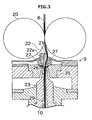
- the spinning device 9 includes a nozzle block 35, a hollow guide shaft member 23, and a fiber guiding member 22.
- a spinning chamber 26 is formed between the nozzle block 35 and the hollow guide shaft member 23.
- An air ejection nozzle 27 from which air is ejected into the spinning chamber 26 is formed in the nozzle block 35.
- An inlet 21 through which the fiber bundle 8 is introduced into the spinning chamber 26 is formed in the fiber guiding member 22.
- the air ejection nozzle 27 can generate a swirling airflow by ejecting air into the spinning chamber 26.
- the fiber guiding member 22 that has the inlet 21 guides the fiber bundle 8 supplied from the drafting device 7 into the spinning chamber 26.
- the fiber bundle 8 is twisted into the spun yarn 10 by being swirled around the hollow guide shaft member 23 by the swirling airflow in the spinning chamber 26.
- the formed spun yarn 10 passes through a yarn passage 29 provided at a shaft center of the hollow guide shaft member 23 to be delivered to the outside of the spinning device 9 via a not shown yarn outlet on a downstream side.
- a guide needle 22a is arranged in the inlet 21 such that the tip of the guide needle 22a points the inside of the spinning chamber 26.
- the fiber bundle 8 introduced through the inlet 21 is guided into the spinning chamber 26 so as to be wound onto the guide needle 22a.
- the fiber bundle 8 guided in this way is introduced into the spinning chamber 26 stably.
- a portion of the fiber bundle 8 upstream than the fiber guiding member 22 is prevented from being twisted even when the fiber bundle 8 is being twisted in the spinning chamber 26.
- the drafting device 7 is prevented from being influenced by a twisting motion imparted by the spinning device 9.
- a configuration in which a downstream end portion of the fiber guiding member 22 is formed to serve as the guide needle 22a and the guide needle 22a is omitted can be employed.
- the winding device 13 is arranged downstream of the spinning device 9.
- the winding device 13 includes a cradle arm 71, a winding drum 72, and a traverse device 75.
- the winding drum 72 is rotated in one direction at a fixed rotational speed.
- the cradle arm 71 can rotatably support the bobbin 48 onto which the spun yarn 10 is to be wound.
- the cradle arm 71 is supported on a support shaft 73 and swingable thereabout.
- the cradle arm 71 swings about the support shaft 73 while supporting the bobbin 48 (or the package 45), thereby causing an outer peripheral surface of the bobbin 48 (or the package 45) to come into contact with or be separated from the winding drum 72.
- the spun yarn 10 can be wound onto the bobbin 48 (or the package 45) in this way.
- the direction in which the winding drum 72 rotates the package 45 is referred to as "winding direction”.
- the winding drums 72 of the winding devices 13 of the spinning units 2 are rotated in unison by the not shown driving source that is shared among the spinning units 2.
- This driving source is arranged in the motor box 5. Accordingly, the spinning units 2 can cause the packages 45 to rotate in unison at the same circumferential velocity to wind the spun yarns 10 in unison.
- the traverse device 75 includes a traverse guide 76 on which the spun yarn 10 can be hooked.
- the traverse guide 76 is reciprocated in a direction parallel to the axial direction of the winding drum 72 by a not shown driving section.
- the driving section is arranged in the motor box 5.
- the traverse guide 76 on which the spun yarn 10 is hooked is reciprocated while the winding drum 72 is rotated. As a result, the spun yarn 10 is wound to form the package 45 while being traversed.
- the yarn pooling device 12 is arranged between the spinning device 9 and the winding device 13. As shown in FIG. 2 , the yarn pooling device 12 includes a yarn pooling roller 14 and an electric motor 25 that rotates the yarn pooling roller 14.
- the yarn pooling roller 14 can pool a certain amount of the spun yarn 10 by winding the spun yarn 10 on its outer peripheral surface.
- the yarn pooling roller 14 is rotated at a predetermined rotational speed in a state where the spun yarn 10 is wound on its outer peripheral surface.
- the yarn pooling device 12 functions as a buffer between the spinning device 9 and the winding device 13 because the yarn pooling device 12 temporarily pools the spun yarn 10 on the outer peripheral surface of the yarn pooling roller 14.
- the yarn pooling roller 14 can resolve a problem of a difference between a spinning speed of the spinning device 9 and a winding speed of the winding device 13 caused by some reason (e.g., slack in the spun yarn 10).
- a yarn-quality measuring device 59 is arranged at a position between the spinning device 9 and the yarn pooling device 12.
- the spun yarn 10 spun by the spinning device 9 passes through the yarn-quality measuring device 59 before the spun yarn 10 is wound onto the yarn pooling device 12.
- the yarn-quality measuring device 59 monitors the thickness of the running spun yarn 10 using a not shown electrical capacitance sensor.
- the yarn-quality measuring device 59 detects a yarn defect (a portion where the thickness or the like of the spun yarn 10 is anomalous) in the spun yarn 10, the yarn-quality measuring device 59 transmits a yarn-defect detection signal to a not shown unit controller.
- a sensor is not limited to an electrical capacitance sensor, but can be a light transmission sensor, for example.
- the yarn-quality measuring device 59 can also be made to detect whether a foreign material is contained in the spun yarn 10 as a yarn defect.
- a not shown cutter is arranged near the yarn-quality measuring device 59.
- the cutter cuts the spun yarn 10 immediately when the yarn-quality measuring device 59 detects a yarn defect in the spun yarn 10.
- the spun yarn 10 can be cut by suspending generation of the spun yarn 10 by stopping an air supply to the spinning device 9.
- a yarn-joining-carrier rail 41 extending in a direction along which the spinning units 2 are arranged side by side is arranged on the frame 6 of the spinning frame 1.
- the yarn-joining carrier 3 can travel on the yarn-joining-carrier rail 41. Therefore, the yarn-joining carrier 3 can move among positions corresponding to a plurality of the spinning units 2.
- the yarn-joining carrier 3 includes a yarn joining device 43, a yarn catching section (a suction pipe 44 and a suction mouth 46), a yarn joint monitor (yarn-joint monitoring device) 47, a reverse driving mechanism 49, and a moving mechanism 30.
- the yarn-joining carrier 3 includes a not shown carrier controller for controlling various components of the yarn-joining carrier 3.
- the suction pipe 44 and the suction mouth 46 are pivotable up and down about respective shafts.
- the suction pipe 44 can suck and catch a yarn end of the spun yarn 10 delivered from the spinning device 9 by generating a suction airflow at a distal end of the suction pipe 44 (see FIG. 5 ).
- the suction mouth 46 can suck and catch a yarn end of the spun yarn 10 coming from the package 45 supported on the winding device 13 by generating a suction airflow at a distal end of the suction mouth 46 (see FIG. 5 ).
- the suction pipe 44 and the suction mouth 46 pivot while sucking and catching the yarn ends of the spun yarn 10, thereby guiding the yarn ends of the spun yarn 10 to a position where the yarn ends face a front surface (on the left side in FIG. 6 ) of the yarn joining device 43 (as shown in FIG. 6 ).
- the carrier controller controls movements of the suction pipe 44 and the suction mouth 46.
- the yarn joining device 43 can join (connect) the yarn end of the spun yarn 10 guided by the suction pipe 44 and coming from the spinning device 9 and the yarn end of the spun yarn 10 guided by the suction mouth 46 and coming from the package 45.
- the yarn joining device 43 is configured as a splicer that forms a yarn joint by twisting the yarn ends using a swirling airflow.
- the yarn joining device 43 need not necessarily be a splicer, but can be a mechanical knotter, for example.
- the carrier controller controls the yarn joining by the yarn joining device 43. When the yarn-joining carrier 3 has stopped at a position corresponding to one of the spinning units 2, the yarn joining device 43 is positioned between the winding device 13 and the yarn pooling device 12 in the running direction of the spun yarn 10.
- the moving mechanism 30 can move the yarn joining device 43 toward or away from the yarn path (the running path of the spun yarn 10; the yarn path extends vertically in FIG. 2 ) during normal winding.
- the yarn joining device 43 performs a yarn joining operation at a position (the position shown in FIG. 7 , for example) where the yarn joining device 43 has approached the yarn path during normal winding. This position of the yarn joining device 43 is referred to as "the yarn joining position”.
- the yarn joining device 43 recedes to a position (the position shown in FIG. 2 , for example) where the yarn joining device 43 is away from the yarn path during normal winding when the yarn joining device 43 does not perform the yarn joining operation. This position of the yarn joining device 43 is referred to as "the receded position".
- the moving mechanism 30 includes a rail 37 and an air cylinder 38.
- the rail 37 is arranged on a carrier section of the yarn-joining carrier 3 and is linearly elongated such that a longitudinal direction of the rail 37 is a direction (a front-to-rear direction of the spinning unit 2, which corresponds to the lateral direction in FIG. 2 ) substantially orthogonal to the yarn path during normal winding.
- the yarn joining device 43 is mounted on a support bracket 36.
- the support bracket 36 is supported on the rail 37 to be movable along the longitudinal direction of the rail 37. Accordingly, the yarn joining device 43 mounted on the support bracket 36 is movable in the direction substantially orthogonal to the yarn path during normal winding.
- the air cylinder 38 is a driving source for driving the yarn joining device 43 along the rail 37.
- the air cylinder 38 is attached at its one end to the carrier section of the yarn-joining carrier 3.
- the air cylinder 38 is attached at the other end to the support bracket 36.
- the yarn joining device 43 is linearly movable in the direction (the direction orthogonal to the yarn path during normal winding) along the rail 37 responsive to an extending/retracting motion of the air cylinder 38.
- the carrier controller controls the extending/retracting motion of the air cylinder 38.
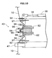
- the yarn joining device 43 includes a yarn joining nozzle 94, clamping sections 97, yarn-path regulating members (a yarn handling lever 96 and a yarn holding lever 98), cutters 92, and untwisting pipes 82.
- the yarn joining nozzle (twisting section) 94 is arranged on the front side of the yarn joining device 43.
- the yarn joining nozzle 94 has a yarn joining hole 90 through which the spun yarn 10 can pass.
- the yarn joining hole 90 internally has a not shown discharge jetting port through which compressed air is to be jetted.
- the yarn joining nozzle 94 generates a swirling airflow inside the yarn joining hole 90 by jetting compressed air into the yarn joining hole 90 through the discharge jetting port.
- the yarn joining device 43 includes the two untwisting pipes (untwisting sections) 82.
- the untwisting pipes 82 extend parallel to each other in the front-to-rear direction of the yarn joining device 43.
- the two untwisting pipes 82 are arranged side by side to form a row in a direction substantially parallel to the running direction of the spun yarn.
- Each of the untwisting pipes 82 has an end that is open toward the front surface of the yarn joining device 43.
- Each of the untwisting pipes 82 includes an air blow hole, through which compressed air is to be jetted into the untwisting pipe 82 to generate an airflow that flows toward a back side (the side opposite to the yarn path).
- the yarn joining nozzle 94 and the untwisting pipes 82 are fixed onto a body of the yarn joining device 43. Accordingly, the yarn joining nozzle 94 and the untwisting pipes 82 move in one piece with the yarn joining device 43 when the yarn joining device 43 is moved by the moving mechanism 30.
- the yarn-path regulating members are lever-like members that are pivotably mounted on the body of the yarn joining device 43. Only cross sections of the yarn handling lever 96 and the yarn holding lever 98 are shown in FIGS. 8 to 10 and 12 .
- the yarn handling lever 96 and the yarn holding lever 98 are arranged so as to come into contact with the spun yarn 10 to regulate the yarn path of the spun yarn 10.
- FIG. 8 and other drawings show how the yarn handling lever 96 and the yarn holding lever 98 regulate the yarn path.
- Each of the yarn handling lever 96 and the yarn holding lever 98 is pivotable to a position where the yarn handling lever 96 or the yarn holding lever 98 does not contact the spun yarn 10. As a result of this pivoting, the spun yarn 10 is released from the regulation imposed by the yarn handling lever 96 and the yarn holding lever 98.
- Each of the two clamping sections 97 is arranged above and below the yarn joining nozzle 94, respectively, in the yarn running direction.
- the clamping sections 97 are operable to open and close and capable of holding the spun yarn 10 in a closed state.
- Each of the two cutters 92 is arranged above and below the yarn joining nozzle 94, respectively, in the yarn running direction. Each of the cutters 92 can cut the spun yarn 10.
- the yarn joining device 43 includes a not shown cam mechanism for causing the yarn handling lever 96 and the yarn holding lever 98 to pivot, for opening and closing the clamping sections 97, and for causing the cutters 92 to perform cutting.
- the yarn joining device 43 includes an electric motor 60 that is a driving source for the cam mechanism. It is possible to hold and cut the spun yarn 10 and regulate the yarn path of the spun yarn 10 at a desired timing by appropriately controlling driving of the electric motor 60.
- the carrier controller controls driving of the electric motor 60. As shown in FIG. 2 and other drawings, the electric motor 60 is arranged near the body of the yarn joining device 43 and fixed to the body of the yarn joining device 43.
- the yarn joint monitor 47 that measures quality of the spun yarn 10 joined by the yarn joining device 43 is arranged immediately downstream of the yarn joining device 43.
- the yarn joint monitor 47 monitors the thickness of a yarn joint formed by the yarn joining device 43 using an electrical capacitance sensor.
- the yarn joint monitor 47 does not necessarily use an electrical capacitance sensor, but can monitor the thickness of the yarn joint using a light transmission sensor, for example.
- the yarn joint monitor 47 transmits a detection signal indicative of the detection result to the carrier controller.
- the reverse driving mechanism 49 includes a first support arm 61 and a second support arm 62, a reverse-rotating roller (contact roller) 63, a linking rod 64, and a reverse-rotating-roller extending/retracting air cylinder 66.
- the reverse driving mechanism 49 includes a reverse-rotating-roller driving motor 67, which is a driving source for the reverse-rotating roller 63.
- the first support arm 61 is swingably coupled to a cabinet section of the yarn-joining carrier 3.
- the second support arm 62 is swingably coupled to the other end of the first support arm 61.
- the reverse-rotating roller 63 is rotatably mounted on a distal end of the second support arm 62.
- the linking rod 64 has a basal end that is pivotable relative to the cabinet section of the yarn-joining carrier 3.
- the linking rod 64 is coupled at its distal end to the second support arm 62.
- the reverse-rotating-roller extending/retracting air cylinder 66 is attached to the linking rod 64.
- the linking rod 64 is pivotable responsive to an extending/retracting motion of the reverse-rotating-roller extending/retracting air cylinder 66.
- the first support arm 61, the second support arm 62, and the linking rod 64 form a link mechanism.
- the reverse-rotating roller 63 at the distal end of the second support arm 62 is advanced or retreated responsive to the extending/retracting motion, which is controlled, of the reverse-rotating-roller extending/retracting air cylinder 66 connected to the link mechanism.
- the reverse-rotating roller 63 can be moved between the "receded position" (the position shown in FIG. 2 , for example) where the reverse-rotating roller 63 does not contact the package 45 and the "contact position" (the position shown in FIG. 5 , for example) where the reverse-rotating roller 63 contacts the package 45.
- the reverse-rotating-roller extending/retracting air cylinder 66 can be regarded as a roller moving mechanism. Meanwhile, the carrier controller controls the motion of the reverse-rotating-roller extending/retracting air cylinder 66.
- a driving force from the reverse-rotating-roller driving motor 67 is input to a pivot support of the first support arm 61.
- the driving force from the reverse-rotating-roller driving motor 67 is input to an intermediate pulley 69, which is at a pivot support of the second support arm 62, via a first transmission belt 68 arranged inside the first support arm 61.
- the driving force input to the intermediate pulley 69 is further input to a driving input pulley 50 via a second transmission belt 70 arranged inside the second support arm 62.
- a clutch 51 is arranged between the driving input pulley 50 and the reverse-rotating roller 63.
- the reverse-rotating roller 63 When the clutch 51 is engaged, the reverse-rotating roller 63 is rotated by the driving force from the reverse-rotating-roller driving motor 67. When the clutch 51 is disengaged, the reverse-rotating roller 63 is separated from the reverse-rotating-roller driving motor 67, allowing the reverse-rotating roller 63 to rotate freely.
- the carrier controller controls such a motion of the clutch 51.
- the reverse driving mechanism 49 includes a rotary encoder mechanism 52 that detects a rotational speed of the reverse-rotating roller 63.
- the rotary encoder mechanism 52 includes a plurality of magnets 53 arranged at equal intervals along the circumference of the reverse-rotating roller 63 and a Hall effect sensor 54 that outputs a pulse signal upon detection of the magnets 53.
- the magnets 53 rotate in one piece with the reverse-rotating roller 63.
- the Hall effect sensor 54 is attached to the second support arm 62.
- the Hall effect sensor 54 outputs a pulse signal responsive to rotation of the reverse-rotating roller 63.
- a detection result (the pulse signal output from the Hall effect sensor 54) is output from the rotary encoder mechanism 52 to the carrier controller.
- the yarn joining operation performed by the yarn-joining carrier 3 is explained below. This yarn joining operation is performed when the spun yarn 10 is broken between the spinning device 9 and the package 45 in one of the spinning units 2 for some reason.
- the unit controller of this target spinning unit 2 drives the cradle arm 71 to swing and exerts control to move the package 45 away from the winding drum 72 and also activates a not shown braking mechanism of the winding device 13. As a result, the package 45 stops rotating.
- the unit controller transmits a control signal to the yarn-joining carrier 3.
- the yarn-joining carrier 3 moves on the yarn-joining-carrier rail 41 to the target spinning unit 2 and stops.
- the moving mechanism 30 maintains the yarn joining device 43 at the receded position when the yarn-joining carrier 3 moves to a position corresponding to the target spinning unit 2 among the spinning units 2.
- the carrier controller causes the suction pipe 44 and the suction mouth 46 to pivot as shown in FIG. 5 and suck and catch the yarn end coming from the spinning device 9 and the yarn end coming from the package 45, respectively.
- the carrier controller brings the reverse-rotating roller 63 into contact with the package 45 by controlling the reverse-rotating-roller extending/retracting air cylinder 66 to cause the reverse-rotating roller 63 to advance to the contact position. Furthermore, the carrier controller engages the clutch 51 and drives the reverse-rotating-roller driving motor 67 to rotate the reverse-rotating roller 63 in the direction opposite to the rotation of the winding drum 72. As a result, the package 45 is rotated in the direction (hereinafter, "the unwinding direction") opposite to the winding direction.
- the unwinding direction opposite to the winding direction.
- the carrier controller causes the suction pipe 44 and the suction mouth 46 that are holding the yarn ends of the spun yarn 10 to pivot in the opposite directions, thereby guiding the caught yarn ends of the spun yarn 10 to the position where the yarn ends face the front surface of the yarn joining device 43 (as shown in FIG. 6 ).
- the carrier controller causes the reverse-rotating-roller driving motor 67 to stop rotation.
- the carrier controller disengages the clutch 51 to decouple the reverse-rotating roller 63 from the reverse-rotating-roller driving motor 67. As a result, rotation of the reverse-rotating roller 63 is stopped, and the package 45 is brought to rest.
- the carrier controller controls the reverse-rotating-roller extending/retracting air cylinder 66 so that even after the reverse-rotating roller 63 stops rotating the package 45 in the reverse direction, the reverse-rotating roller 63 does not recede but keeps a contact state where the reverse-rotating roller 63 is in contact with the outer peripheral surface of the package 45.
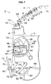
- the moving mechanism 30 causes the air cylinder 38 to extend to move the yarn joining device 43 toward the yarn path until the yarn joining device 43 is advanced to the yarn joining position.
- the yarn joining device 43 is advanced to the yarn joining position, the yarn end of the spun yarn 10 caught by the suction pipe 44 and coming from the spinning device 9 and the yarn end of the spun yarn 10 caught by the suction mouth 46 and coming from the package 45 are introduced into the yarn joining device 43 (as shown in FIG. 7 ).
- the yarn joint monitor 47 is arranged such that the spun yarn 10 is introduced into the yarn joint monitor 47 when the moving mechanism 30 has moved the yarn joining device 43 to the yarn joining position. Accordingly, when the yarn joining device 43 has advanced to the yarn joining position, the yarn joint monitor 47 can inspect the spun yarn 10.
- the yarn joining device 43 advanced to the yarn joining position causes the yarn handling lever 96 to pivot into contact with the spun yarn 10.
- the yarn path is regulated so as to introduce the spun yarn 10 into the yarn joining hole 90 in the yarn joining nozzle 94 (as shown in FIG. 8 ).
- the yarn joining device 43 causes the clamping sections 97 to hold the spun yarn 10 in this state by closing the clamping sections 97.
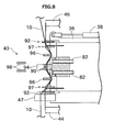
- the carrier controller causes jetting of compressed air into the untwisting pipes 82 to start.
- an airflow that flows toward a back side (the right side in FIG. 8 ) of the yarn joining device 43 is generated in the untwisting pipes 82.
- a suction airflow is generated at openings on a front side (the left side in FIG. 8 ) of the untwisting pipes 82.
- the carrier controller activates the cutters 92 to cut the spun yarn 10 between the suction pipe 44 and the yarn joining device 43 and the spun yarn 10 between the suction mouth 46 and the yarn joining device 43.
- Yarn ends resulting from this cutting are independently sucked by the untwisting pipes 82 and drawn inside the untwisting pipes 82.
- the yarn ends sucked into the untwisting pipes 82 are untwisted by actions of the airflows in the untwisting pipes 82 (see FIG. 9 ).
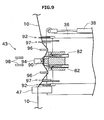
- the carrier controller causes compressed air jetting into the untwisting pipes 82 to discontinue. Furthermore, the carrier controller causes the yarn handling lever 96 and the yarn holding lever 98 to further bend the yarn path of the spun yarn 10, thereby drawing out the untwisted yarn ends from the untwisting pipes 82.
- the yarn ends drawn out from the untwisting pipes 82 are set in the yarn joining hole 90 in the yarn joining nozzle 94 in a state where the yarn ends are overlaid on each other (see FIG. 10 ). Compressed air is jetted into the yarn joining hole 90 in this state so that a swirling airflow is generated in the yarn joining hole 90 to twist fibers of the yarn ends.
- the carrier controller causes compressed air jetting into the yarn joining hole 90 to discontinue. Furthermore, the carrier controller releases the spun yarn 10 held by the clamping sections 97 by opening the clamping sections 97 and also releases the yarn path from the regulation imposed by the yarn handling lever 96 and the yarn holding lever 98. Substantially concurrently therewith, the unit controller of the spinning unit 2 causes the cradle arm 71 to pivot to bring the outer peripheral surface of the package 45 into contact with the rotating winding drum 72 (as shown in FIG. 11 ).
- the package 45 is moved toward the winding drum 72.
- the reverse driving mechanism 49 of the yarn-joining carrier 3 causes the reverse-rotating roller 63 to follow the moving package 45 to maintain the contact state where the reverse-rotating roller 63 is in contact with the package 45.
- Winding of the spun yarn 10 is resumed because the package 45 is brought into contact with the winding drum 72 to resume rotating.
- the reverse-rotating roller 63 that is in contact with the package 45 is rotated by the rotation of the package 45.
- the rotary encoder mechanism 52 inputs a pulse signal responsive to the rotation of the reverse-rotating roller 63 to the carrier controller.
- the carrier controller determines the rotational speed of the reverse-rotating roller 63 based on the pulse signal.
- the carrier controller determines the rotational speed of the package 45 from the rotational speed of the reverse-rotating roller 63 obtained based on the pulse signal fed from the rotary encoder mechanism 52.
- the rotational speed of the package 45 can be determined accurately based on the rotational speed of the reverse-rotating roller 63 because the reverse-rotating roller 63 is rotated (to make free rotation) by the rotation of the package 45.
- the rotational speed of the package 45 is determined based on a result of detection output from the rotary encoder mechanism 52 in this way. Accordingly, the rotary encoder mechanism 52 can be regarded as a speed detecting section.
- the "rotational speed" of the package 45 to be obtained by the carrier controller can be any information indicating the rotational speed of the package 45 and is not limited to a specific form. Examples of the information include an angular velocity of the package 45, a circumferential velocity of the package 45, and the number of rotations of the package 45 per unit time.
- the circumferential velocity of the package 45 is obtained easily based on the rotational speed of the reverse-rotating roller 63 because the reverse-rotating roller 63 is in contact with the outer peripheral surface of the package 45 and is rotated by the package 45.
- the carrier controller according to the present embodiment obtains the circumferential velocity of the package 45 as the rotational speed of the package 45.
- a yarn joint 99 formed by the yarn joining device 43 passes through the yarn joint monitor 47 as shown in FIG. 12 .
- the yarn joint monitor 47 inspects the yarn joint 99 when the yarn joint 99 passes therethrough and outputs an inspection result.
- the carrier controller judges the quality of the yarn joint 99 based on the inspection result. Accordingly, the carrier controller can be regarded as a judging section.
- the yarn-joining carrier 3 cuts and removes the defective joint using a not shown cutter and causes the yarn joining device 43 to perform yarn joining again, for example.
- the carrier controller When determining, for example, the length of the yarn joint 99, the carrier controller requires information about time spent by the yarn joint 99 to pass through the yarn joint monitor 47 and information about the velocity (in other words, the running speed of the spun yarn 10) at which the yarn joint 99 passes through the yarn joint monitor 47.
- the carrier controller calculates the running speed of the spun yarn 10 based on the circumferential velocity of the package 45 obtained as described above.
- the spun yarn 10 is run by being wound onto the outer peripheral surface of the package 45. Accordingly, the running speed (yarn speed) of the spun yarn 10 can be calculated easily from the circumferential velocity of the package 45.
- the carrier controller judges the quality of the yarn joint 99 based on the running speed of the spun yarn 10 obtained as described above and the inspection result output from the yarn joint monitor 47.
- the quality of the yarn joint 99 is judged based on the running speed of the spun yarn 10 obtained based on the actually-measured rotational speed of the package 45. Therefore, the quality of the yarn joint 99 can be determined accurately.
- the rotational speed of the package 45 based on the rotational speed of the winding drum 72 because the package 45 is rotating also in contact with the winding drum 72.
- the winding drums 72 in multiple spinning units 2 are continuously rotated together by the one driving source at a constant rotational speed. Bringing the package 45, which is in a rotation-stopped state, into contact with the winding drum 72, which is continuously rotating at a constant speed, causes slippage to occur between the package 45 and the winding drum 72. For this reason, it is not preferable to obtain the rotational speed of the package 45 from the rotational speed of the winding drum 72 immediately after resumption of winding.
- the rotational speed of the package 45 is calculated based on the rotational speed of the other roller (the reverse-rotating roller 63) than the winding drum 72. Accordingly, even in the spinning frame 1 in which the winding drums 72 in multiple spinning units 2 are driven together, the rotational speed of the package 45 can be accurately obtained on an individual package basis.
- the moving mechanism 30 causes the yarn joining device 43 to recede to its receded position.
- the carrier controller controls the reverse-rotating-roller extending/retracting air cylinder 66 so as to move the reverse-rotating roller 63 away from the package 45 to its receded position. This permits the yarn-joining carrier 3 to move to another spinning unit 2.
- the spinning frame 1 includes the winding devices 13, the spinning devices 9, the rotary encoder mechanism 52, the yarn joining device 43, the yarn joint monitor 47, and the carrier controller.
- Each of the winding devices 13 winds the spun yarn 10 to form the package 45.
- Each of the spinning devices 9 supplies the spun yarn 10 to the winding device 13.
- the rotary encoder mechanism 52 detects and outputs the rotational speed of the package 45.
- the yarn joining device 43 joins the yarn end of the spun yarn 10 coming from the spinning device 9 and the yarn end of the spun yarn 10 coming from package 45 and forms the yarn joint 99.
- the yarn joint monitor 47 arranged downstream of the yarn joining device 43 in the running direction of the spun yarn 10 monitors the yarn joint 99 and outputs a monitoring result.
- the carrier controller judges whether the yarn joint 99 formed by the yarn joining device 43 is normal based on the monitoring result output from the yarn joint monitor 47 and the running speed of the spun yarn 10 obtained based on the rotational speed output from the rotary encoder mechanism 52.
- the yarn speed at resumption of winding can be obtained accurately based on the actually-measured value of the rotational speed of the package 45 as described above. Judging the quality of the yarn joint 99 based on the yarn speed obtained in this way leads to accurate determination of the quality of the yarn joint 99.
- the spinning frame 1 includes the reverse-rotating roller 63 that comes into contact with the package 45 to be rotated by the package 45.
- the rotary encoder mechanism 52 detects the rotational speed of the reverse-rotating roller 63.
- the rotational speed of the package 45 can be obtained accurately based on the rotational speed of the reverse-rotating roller 63 that is in contact with the package 45 and rotated thereby.
- the spinning frame 1 includes a plurality of the spinning units 2 each of which includes the spinning device 9 and the winding device 13.
- the winding device 13 of the spinning unit 2 includes the winding drum 72 that rotates the package 45 in the direction in which the spun yarn 10 is wound onto the package 45.
- the spinning frame 1 includes the driving source that drives the winding drums 72 of multiple spinning units 2 together.
- the driving source is arranged in the motor box 5.
- the reverse-rotating roller 63 is arranged as a separate member from the winding drum 72.
- the packages 45 are rotated, as described above, by the winding drums 72 of multiple spinning units 2 that are driven together. Accordingly, the spinning units 2 can wind the spun yarns 10 simultaneously.
- the rotational speeds of the packages 45 cannot be obtained on an individual package basis from the rotational speeds of the winding drums 72 because the winding drums 72 of multiple spinning units 2 are driven together.
- the rotational speed of the package 45 is detected based on the rotational speed of the reverse-rotating roller 63 that is separate from the winding drum 72. Accordingly, an actually-measured value of the rotational speed of the package 45 can be obtained from each yarn winding unit 2 for judgment of the quality of the yarn joint 99.
- the reverse-rotating roller 63 rotates the package 45 in the direction in which the spun yarn 10 is unwound from the package 45.
- the reverse-rotating roller 63 performs two functions: a function of detecting the rotational speed of the package 45 and a function of rotating the package 45 in the reverse direction. Accordingly, the configuration of the spinning frame 1 is simplified.
- the spinning frame 1 includes the reverse-rotating-roller extending/retracting air cylinder 66 and the carrier controller.
- the reverse-rotating-roller extending/retracting air cylinder 66 moves the reverse-rotating roller 63 between the position where the reverse-rotating roller 63 contacts the package 45 and the position where the reverse-rotating roller 63 is separated from the package 45.
- the carrier controller controls rotation of the reverse-rotating roller 63, formation of a yarn joint performed by the yarn joining device 43, and movement of the reverse-rotating roller 63 performed by the reverse-rotating-roller extending/retracting air cylinder 66.
- the carrier controller controls the reverse-rotating-roller extending/retracting air cylinder 66 such that the reverse-rotating-roller extending/retracting air cylinder 66 brings the reverse-rotating roller 63 into contact with the package 45, and simultaneously controls the rotation of the reverse-rotating roller 63 such that the reverse-rotating roller 63 causes the package 45 to rotate in the direction in which the spun yarn 10 is unwound from the package 45.
- the carrier controller controls the yarn joining device 43 such that the yarn joining device 43 forms the yarn joint 99 by joining the yarn end of the spun yarn 10 unwound from the package 45 that is rotated by the reverse-rotating roller 63 and the yarn end of the spun yarn 10 coming from the spinning device 9.
- the carrier controller controls the reverse-rotating-roller extending/retracting air cylinder 66 such that the reverse-rotating-roller extending/retracting air cylinder 66 maintains the state in which the reverse-rotating roller 63 is in contact with the package 45 at least until the yarn joint 99 has passed through the yarn joint monitor 47 after completion of the yarn joining.
- the rotational speed of the package 45 when the yarn joint 99 passes through the yarn joint monitor 47 can be obtained from the rotational speed of the reverse-rotating roller 63 by maintaining the contact state between the reverse-rotating roller 63 and the package 45 after completion of the yarn joining in this way. Therefore, the quality of the yarn joint 99 can be judged accurately.
- the spinning frame 1 includes the reverse-rotating-roller driving motor 67 and the clutch 51 that is engaged or disengaged to control drive transmission linkage between the reverse-rotating roller 63 and the reverse-rotating-roller driving motor 67.
- the clutch 51 performs control such that the drive transmission linkage is decoupled while the yarn joint 99 passes through the yarn joint monitor 47.
- This control allows rotating the reverse-rotating roller 63 without resistance while the yarn joint 99 passes through the yarn joint monitor 47. As a result, the rotational speed of the package 45 can be obtained accurately using the reverse-rotating roller 63.
- the spinning frame 1 includes the yarn-joining carrier 3 that includes the yarn joining device 43, the yarn joint monitor 47, and the reverse-rotating roller 63.
- the yarn-joining carrier 3 is capable of moving among positions corresponding to the spinning units 2.
- the yarn-joining carrier 3 moves and stops near the target spinning unit 2 in which the spun yarn 10 is broken among the spinning units 2 and causes the yarn joining device 43 to perform yarn joining on the spinning unit 2.
- the spinning frame 1 by arranging the yarn-joining carrier 3 that moves while carrying the components necessary for yarn joining thereon, a configuration of the entire spinning frame 1 is simplified, thereby achieving cost reduction, as compared with a spinning frame in which each of the spinning units 2 includes the components necessary for yarn joining.
- the spinning device 9 of the spinning frame 1 is an air spinning device that generates the spun yarn 10 by twisting the fiber bundle 8 using a swirling airflow.
- the winding device 13 winds the spun yarn 10 at a high speed because typical air spinning devices can perform high-speed spinning. For this reason, the spun yarn 10 is accelerated suddenly at resumption of winding, and it is difficult to estimate the running speed of the spun yarn 10 using an empirical equation or the like.
- the spinning frame 1 that includes such an air spinning device can obtain the running speed of the spun yarn 10 accurately by adopting the configuration according to the present embodiment that detects the running speed of the spun yarn 10 based on the actually-measured value of the rotational speed of the package 45.
- the rotational speed of the package 45 is detected using the reverse-rotating roller 63.
- a modification may be made such that a contact roller to be brought into contact with and rotated by the package 45 for detection of the rotational speed of the package 45 is additionally provided separate from the reverse-rotating roller 63.
- the carrier controller of the yarn-joining carrier 3 judges the quality of the yarn joint 99.
- a modification may be made such that the unit controller of the spinning unit 2 and/or a central control section that controls the entire spinning frame 1, for example, judges the quality of the yarn joint 99.
- the yarn-joining carrier 3 includes the yarn joining device 43 and the like.
- a modification may be made such that the spinning unit 2 includes the winding device 13, the spinning device 9, the rotary encoder mechanism 52, the yarn joining device 43, the yarn joint monitor 47, and a unit controller.
- the winding device 13 winds the spun yarn 10 to form the package 45.
- the spinning device 9 supplies the spun yarn 10 to the winding device 13.
- the rotary encoder mechanism 52 detects and outputs the rotational speed of the package 45.
- the yarn joining device 43 joins the spun yarn 10 between the spinning device 9 and the package 45 and forms the yarn joint 99.
- the yarn joint monitor 47 arranged downstream of the yarn joining device 43 in the running direction of the spun yarn 10 monitors the yarn joint 99 and outputs a monitoring result.
- the unit controller judges whether the yarn joint 99 formed by the yarn joining device 43 is normal based on the monitoring result output from the yarn joint monitor 47 and the running speed of the spun yarn 10 obtained based on the rotational speed output from the rotary encoder mechanism 52.
- a modification may be made such that the components that are provided in the yarn-joining carrier 3 in the present embodiment are provided in each of the spinning units 2 rather than in the yarn-joining carrier 3.
- the spun yarn 10 runs downward in the vertical direction.
- the direction in which the spun yarn 10 runs is not limited to a specific direction. A modification may be made such that the spun yarn 10 runs upward, for example.
- the yarn path of the spun yarn 10 runs substantially in a vertical direction in FIG. 2 and other drawings.
- a modification may be made such that in a case where the winding device 13 is arranged on a back side of the spinning unit 2 with respect to the position shown in FIG. 2 , for example, the yarn path is inclined from the front surface side toward the back side.
- the spinning frame 1 includes one yarn-joining carrier 3 in FIG. 1 and other drawings; alternatively, the spinning frame 1 may include multiple yarn-joining carriers 3 depending on the number of the spinning units 2.
- the roller moving mechanism for advancing or retreating the reverse-rotating roller 63 is not necessarily the air cylinder (the reverse-rotating-roller extending/retracting air cylinder 66), but may be another actuator such as a motor.
- the timing when the clutch 51 is to be disengaged is not limited to the timing when the reverse-rotating roller 63 has stopped reverse rotation of the package 45, but may be disengaged at any time before the yarn joint 99 passes through the yarn joint monitor 47.
- the clutch 51 may be kept being engaged while the yarn joint 99 passes through the yarn joint monitor 47 in a case where a resistance is not given to rotation of the reverse-rotating roller 63 even when a drive transmission linkage from the reverse-rotating-roller driving motor 67 to the reverse-rotating roller 63 is connected. In such a case, the clutch 51 can be omitted.
- a modification may be made such that the reverse-rotating roller 63 is temporarily separated from the package 45 at a point in time where the reverse rotation of the package 45 ends, and thereafter, the reverse-rotating roller 63 is brought into contact with the package 45 again immediately before rotation of the package 45 is resumed.
- the yarn speed at which the yarn joint 99 passes through the yarn joint monitor 47 can be obtained based on the rotational speed of the reverse-rotating roller 63 so long as the reverse-rotating roller 63 is in contact with the package 45 when the yarn joint 99 passes through the yarn joint monitor 47.
- the reverse-rotating roller 63 is separated from the package 45 after inspection of the yarn joint 99 is completed (that is, after the yarn joint 99 has passed through the yarn joint monitor 47). Whether the yarn joint 99 has passed through the yarn joint monitor 47 can be determined based on the monitoring result output from the yarn joint monitor 47. Accordingly, a modification may be made such that the reverse-rotating roller 63 is separated from the package 45 based on the monitoring result output from the yarn joint monitor 47. Another modification may be made such that the reverse-rotating roller 63 is separated from the package 45 when a time period that is sufficiently long for the yarn joint 99 to pass through the yarn joint monitor 47 has elapsed after winding of the spun yarn 10 is resumed by the winding device 13.
- Detection of the rotational speed of the reverse-rotating roller 63 needs not necessarily be performed by the rotary encoder mechanism 52, but can be performed by utilizing any appropriate component.
- the winding drums 72 of multiple spinning units 2 are driven together.
- the winding drums 72 of the spinning units 2 can be driven separately.
- the spinning units 2 can drive the winding drums 72 at different rotational speeds.
- the winding drums 72 are driven at different rotational speeds, it is possible to rotate each of the winding drums 72 in a manner to avoid slippage between the package 45 and the winding drum 72. Therefore, a modification which is not according to the invention may be made in this case so as to obtain the rotational speed of the package 45 based on the rotational speed of the winding drum 72.
- this modification it is also possible to perform control so as to rotate the package 45 in the reverse direction by rotating the winding drum 72 in reverse.
- the spun yarn 10 is pulled out from the spinning device 9 by rotating the yarn pooling roller 14 of the yarn pooling device 12.
- a yarn feeding device can be provided that rotates while pinching the spun yarn between a delivery roller and a nip roller to thereby pull out the spun yarn from a spinning device.
- Components that allow the yarn joining device 43 to move relative to the yarn path can be omitted.
- the spinning device need not necessarily be a spinning device that performs spinning using air, but may be a spinning device of another scheme.
- the yarn winding machine is not limited to the spinning frame 1 but may be a yarn winding machine of another type, such as an automatic winder.
- the winding section includes a winding drum adapted to rotate the package in a direction in which the yarn is wound onto the package and is adapted to wind the yarn to form the package.
- the yarn supplying section is adapted to supply the yarn to the winding section.
- the contact roller is arranged independently from the winding drum and adapted to make contact with the freely rotating package to be rotated by the package.
- the speed detecting section is adapted to detect and output a speed result indicative of detected rotational speed of the contact roller.
- the yarn joining device is adapted to join a yarn end of the yarn coming from the yarn supplying section and a yarn end of the yarn coming from the package to form a yarn joint.
- the yarn-joint monitoring device is arranged downstream of the yarn joining device in a running direction of the yarn and adapted to monitor the yarn joint and output a monitoring result.
- the judging section is adapted to judge whether the yarn joint formed by the yarn joining device is normal based on the speed result output from the speed detecting section and the monitoring result output from the yarn-joint monitoring device.
- the yarn speed at resumption of winding can be obtained accurately based on the actually-measured value of the rotational speed of the package as described above. Judging the quality of the yarn joint based on the yarn speed obtained in this way leads to accurate determination of the quality of the yarn joint.
- the contact roller of the yarn winding machine is a reverse-rotating roller adapted to rotate the package in a direction in which the yarn is unwound from the package.
- the contact roller performs two functions: a function of detecting the rotational speed of the package and a function of rotating the package in the reverse direction. Accordingly, the configuration of the yarn winding machine is simplified.
- the yarn winding machine includes a roller moving mechanism and a control section.
- the roller moving mechanism is adapted to move the contact roller between a position where the contact roller is in contact with the package and a position where the contact roller is separated from the package.
- the control section is adapted to control at least rotation of the contact roller, formation of the yarn joint performed by the yarn joining device, and movement of the contact roller performed by the roller moving mechanism.
- the control section is adapted to control the movement of the contact roller such that the roller moving mechanism brings the contact roller into contact with the package, and simultaneously controls the rotation of the contact roller such that the contact roller rotates the package in a direction in which the yarn is unwound from the package.
- the control section is adapted to control the formation of the yarn joint such that the yarn joining device forms the yarn joint by joining the yarn end of the yarn unwound from the package rotated by the contact roller and the yarn end of the yarn coming from the yarn supplying section.
- the control section is adapted to control the movement of the contact roller such that the roller moving mechanism maintains a state in which the contact roller is in contact with the package at least until the yarn joint has passed through the yarn-joint monitoring device after completion of the yarn joining.
- the rotational speed of the package when the yarn joint passes through the yarn-joint monitoring device can be obtained from the rotational speed of the contact roller by maintaining the state in which the contact roller is in contact with the package after completion of the yarn joining as described above. As a result, the quality of the yarn joint can be judged accurately.
- the yarn winding machine includes a rotation driving source adapted to drive the contact roller and a clutch adapted to be engaged or disengaged to control drive transmission linkage between the contact roller and the rotation driving source.
- the clutch is adapted to perform control such that the drive transmission linkage is decoupled while the yarn joint passes through the yarn-joint monitoring device.
- This control allows rotating the contact roller without resistance while the yarn joint passes through the yarn-joint monitoring device. As a result, the rotational speed of the package can be obtained accurately using the contact roller.
- the yarn winding machine includes a plurality of the yarn winding units, each of which includes the yarn supplying section and the winding section.
- the yarn winding machine further includes a driving source adapted to drive the winding drums of multiple yarn winding units together.
- the winding drums of the yarn winding units that are driven together rotate the packages in this way. Accordingly, the yarn winding units wind the yarns simultaneously.
- the rotational speeds of the packages cannot be obtained on an individual package basis from the rotational speeds of the winding drums because the winding drums of multiple yarn winding units are driven together.
- an actually-measured value of the rotational speed of the package can be obtained from each yarn winding unit for judgment of the quality of the yarn joint when the rotational speed of the package is detected based on the rotational speed of the contact roller that is separate from the winding drum as described above.
- the yarn winding machine further includes a yarn-joining carrier that includes the yarn joining device, the yarn-joint monitoring device, and the contact roller.
- the yarn-joining carrier is capable of moving among positions corresponding to the yarn winding units.
- the yarn-joining carrier is adapted to move and stop near a target yarn winding unit in which the yarn is broken among the yarn winding units, and to cause the yarn joining device to perform yarn joining on the target yarn winding unit.
- the yarn supplying section of the yarn winding machine is an air spinning device adapted to generate a spun yarn by twisting a fiber bundle using a swirling airflow.
- the winding section generally winds the yarn at a high speed because typical air spinning devices are capable of performing high-speed spinning. For this reason, the yarn is accelerated suddenly at resumption of winding, and it is difficult to estimate the running speed of the yarn using an empirical equation or the like.
- the yarn winding machine that includes such an air spinning device can obtain the running speed of the yarn accurately when the yarn winding machine employs the configuration according to the aspect of the present invention that detects the running speed of the yarn based on an actually-measured value of the rotational speed of the package.
- a yarn winding unit adapted to wind a yarn to form a package includes a winding section, a yarn supplying section, a contact roller, a speed detecting section, a yarn joining device, a yarn-joint monitoring device, and a judging section.
- the winding section includes a winding drum adapted to rotate the package in a direction in which the yarn is wound onto the package and is adapted to wind the yarn to form the package.
- the yarn supplying section is adapted to supply the yarn to the winding section.
- the contact roller is arranged independently from the winding drum and is adapted to make contact with the freely rotating package to be rotated by the package.
- the speed detecting section is adapted to detect and output a speed result indicative of detected rotational speed of the contact roller.
- the yarn joining device is adapted to join a yarn end of the yarn coming from the yarn supplying section and a yarn end of the yarn coming from the package and forms a yarn joint.
- the yarn-joint monitoring device is arranged downstream of the yarn joining device in a running direction of the yarn and adapted to monitor the yarn joint and output a monitoring result.
- the judging section is adapted to judge whether the yarn joint formed by the yarn joining device is normal based on the speed result output from the speed detecting section and the monitoring result output from the yarn-joint monitoring device.
- the yarn speed at resumption of winding can be obtained accurately based on the actually-measured value of the rotational speed of the package as described above. Judging the quality of the yarn joint based on the yarn speed obtained in this way leads to accurate determination of the quality of the yarn joint.
Landscapes
- Engineering & Computer Science (AREA)
- Textile Engineering (AREA)
- Quality & Reliability (AREA)
- Spinning Or Twisting Of Yarns (AREA)
Claims (8)
- Eine Vorrichtung zum Prüfen einer Garnverbindung eines in einer Garnaufwickeleinheit aufgewickelten Garns, wobei die Garnaufwickeleinheit einen Aufwickelabschnitt (13) umfasst, der dazu angepasst ist, ein Garn (10) aufzuwickeln, um einen Garnkörper (45) zu bilden, wobei der Aufwickelabschnitt (13) eine Aufwickelwalze (72), die dazu angepasst ist, den Garnkörper (45) in einer Richtung zu drehen, in der das Garn (10) auf den Garnkörper (45) aufgewickelt wird, und einen Garnzuführabschnitt (9), der dazu angepasst ist, das Garn (10) dem Aufwickelabschnitt (13) zuzuführen, umfasst, wobei die Vorrichtung dadurch gekennzeichnet ist, dass sie folgende Merkmale aufweist:eine Kontaktrolle (63), die unabhängig von der Aufwickelwalze (72) angeordnet ist und dazu angepasst ist, mit dem sich frei drehenden Garnkörper (45) in Kontakt zu gelangen, um durch den Garnkörper (45) gedreht zu werden;einen Geschwindigkeitserfassungsabschnitt (52), der dazu angepasst ist, ein Geschwindigkeitsergebnis, das eine erfasste Drehgeschwindigkeit der Kontaktrolle (63) angibt, zu erfassen und auszugeben;eine Garnverbindungsvorrichtung (43), die dazu angepasst ist, ein Garnende des Garns (10) von dem Garnzuführabschnitt (9) und ein Garnende des Garns (10) von dem Garnkörper (45) zu verbinden, um eine Aufwickelwalze (99) zu bilden;eine Garnverbindungsüberwachungsvorrichtung (47), die in Verarbeitungsrichtung nach der Garnverbindungsvorrichtung (43) in einer Laufrichtung des Garns (10) angeordnet ist und dazu angepasst ist, die Aufwickelwalze (99) zu überwachen und ein Überwachungsergebnis auszugeben; undeinen Bewertungsabschnitt, der dazu angepasst ist, auf der Basis des aus dem Geschwindigkeitserfassungsabschnitt (52) ausgegebenen Geschwindigkeitsergebnisses und des aus der Garnverbindungsüberwachungsvorrichtung (47) ausgegebenen Überwachungsergebnisses zu bewerten, ob die durch die Garnverbindungsvorrichtung (43) gebildete Aufwickelwalze (99) normal ist.
- Die Vorrichtung gemäß Anspruch 1, bei der die Kontaktrolle (63) eine sich entgegengesetzt drehende Rolle (63) ist, die dazu angepasst ist, den Garnkörper (45) in einer Richtung zu drehen, in der das Garn (10) von dem Garnkörper (45) abgewickelt wird.
- Die Vorrichtung gemäß Anspruch 1 oder 2, die ferner folgende Merkmale aufweist:einen Rollenbewegungsmechanismus (66), der dazu angepasst ist, die Kontaktrolle (63) zwischen einer Position, in der die Kontaktrolle (63) in Kontakt mit dem Garnkörper (45) ist, und einer Position, in der die Kontaktrolle (63) von dem Garnkörper (45) getrennt ist, zu bewegen; undeinen Steuerabschnitt, der dazu angepasst ist, zumindest eine Drehung der Kontaktrolle (63), eine durch die Garnverbindungsvorrichtung (43) durchgeführte Bildung der Aufwickelwalze (99) und eine Bewegung der Kontaktrolle (63), die durch den Rollenbewegungsmechanismus (66) durchgeführt wird, zu steuern, wobeider Steuerabschnitt dann, wenn das Garn (10) zwischen dem Garnzuführabschnitt (9) und dem Garnkörper (45) gebrochen wird, dazu angepasst ist, die Bewegung der Kontaktrolle (63) derart zu steuern, dass der Rollenbewegungsmechanismus (66) die Kontaktrolle (63) in Kontakt mit dem Garnkörper (45) bringt, und dazu, gleichzeitig die Drehung der Kontaktrolle (63) zu steuern, sodass die Kontaktrolle (63) den Garnkörper (45) in einer Richtung dreht, in der das Garn (10) von dem Garnkörper (45) abgewickelt wird,der Steuerabschnitt dazu angepasst ist, die Bildung der Aufwickelwalze (99) derart zu steuern, dass die Garnverbindungsvorrichtung (43) die Aufwickelwalze (99) bildet, indem sie das Garnende des Garns (10), das von dem durch die Kontaktrolle (63) gedrehten Garnkörper (45) abgewickelt wird, und das Garnende des Garns (10) von dem Garnzuführabschnitt (9) verbindet, undder Steuerabschnitt dazu angepasst ist, die Bewegung der Kontaktrolle (63) derart zu steuern, dass der Rollenbewegungsmechanismus (66) einen Zustand aufrecht erhält, in dem die Kontaktrolle (63) zumindest so lange in Kontakt mit dem Garnkörper (45) ist, bis die Aufwickelwalze (99) nach Abschluss des Garnverbindungsvorgangs die Garnverbindungsüberwachungsvorrichtung (47) passiert hat.
- Die Vorrichtung gemäß einem der Ansprüche 1 bis 3, die ferner folgende Merkmale aufweist:eine Drehantriebsquelle (67), die dazu angepasst ist, die Kontaktrolle (63) anzutreiben; undeine Kupplung (51), die dazu angepasst ist, eingekuppelt oder ausgekuppelt zu werden, um eine Antriebsübertragungsverknüpfung zwischen der Kontaktrolle (63) und der Drehantriebsquelle (67) zu steuern, wobeidie Kupplung (51) dazu angepasst ist, zumindest so lange eine Steuerung der Entkopplung der An-triebsübertragungsverknüpfung durchzuführen, wie die Aufwickelwalze (99) die Garnverbindungsüberwachungsvorrichtung (47) passiert.
- Eine Garnaufwickeleinheit, die folgende Merkmale aufweist:einen Aufwickelabschnitt (13), der dazu angepasst ist, ein Garn (10) aufzuwickeln, um einen Garnkörper (45) zu bilden, wobei der Aufwickelabschnitt (13) eine Aufwickelwalze (72), die dazu angepasst ist, den Garnkörper (45) in einer Richtung zu drehen, in der das Garn (10) auf den Garnkörper (45) aufgewickelt wird;einen Garnzuführabschnitt (9), der dazu angepasst ist, das Garn (10) dem Aufwickelabschnitt (13) zuzuführen; undeine Vorrichtung gemäß einem der Ansprüche 1 bis 4.
- Die Garnaufwickeleinheit gemäß Anspruch 5, bei der der Garnzuführabschnitt (9) eine Luftspinnvorrichtung ist, die dazu angepasst ist, ein gesponnenes Garn (10) zu erzeugen, indem sie ein Faserbündel (8) unter Verwendung eines Luftdralls verdrillt.
- Eine Garnaufwickelmaschine, die folgende Merkmale aufweist:eine oder mehrere Garnaufwickeleinheiten (2) gemäß Anspruch 5 oder 6, wobei jede der Garnaufwickeleinheiten (2) den Garnzuführabschnitt (9) und den Aufwickelabschnitt (13) umfasst; undeine Antriebsquelle, die dazu angepasst ist, die Aufwickelwalzen (72) der einen oder der mehreren Garnaufwickeleinheiten (2) zusammen anzutreiben.
- Die Garnaufwickelmaschine gemäß Anspruch 7, die eine Mehrzahl von Garnaufwickeleinheiten (2) und einen Garnverbindungsträger (3) aufweist, bei der
der Garnverbindungsträger (3) die Garnverbindungsvorrichtung (43), die Garnverbindungsüberwachungsvorrichtung (47) und die Kontaktrolle (63) umfasst,
der Garnverbindungsträger (3) dazu angepasst ist, in der Lage zu sein, sich zwischen Positionen zu bewegen, die den Garnaufwickeleinheiten (2) entsprechen, und
der Garnverbindungsträger (3) dazu angepasst ist, sich in der Nähe einer Zielgarnaufwickeleinheit (2) zu bewegen und anzuhalten, bei der das Garn (10) zwischen den Garnaufwickeleinheiten (2) gebrochen wird, und zu bewirken, dass die Garnverbindungsvorrichtung (43) an der Zielgarnaufwickeleinheit (2) einen Garnverbindungsvorgang durchführt.
Applications Claiming Priority (1)
| Application Number | Priority Date | Filing Date | Title |
|---|---|---|---|
| JP2011206504A JP2013067892A (ja) | 2011-09-21 | 2011-09-21 | 糸巻取機及び糸巻取ユニット |
Publications (3)
| Publication Number | Publication Date |
|---|---|
| EP2573023A2 EP2573023A2 (de) | 2013-03-27 |
| EP2573023A3 EP2573023A3 (de) | 2013-11-13 |
| EP2573023B1 true EP2573023B1 (de) | 2014-08-27 |
Family
ID=46924253
Family Applications (1)
| Application Number | Title | Priority Date | Filing Date |
|---|---|---|---|
| EP20120182390 Not-in-force EP2573023B1 (de) | 2011-09-21 | 2012-08-30 | Garnwickelmaschine und Garnwickeleinheit |
Country Status (3)
| Country | Link |
|---|---|
| EP (1) | EP2573023B1 (de) |
| JP (1) | JP2013067892A (de) |
| CN (1) | CN103010843B (de) |
Families Citing this family (11)
| Publication number | Priority date | Publication date | Assignee | Title |
|---|---|---|---|---|
| ITPD20130115A1 (it) * | 2013-04-30 | 2014-10-31 | Savio Macchine Tessili Spa | Roccatrice |
| JP2015078474A (ja) * | 2013-10-18 | 2015-04-23 | 村田機械株式会社 | 繊維機械 |
| JP2015140252A (ja) * | 2014-01-30 | 2015-08-03 | 村田機械株式会社 | 糸状態表示装置、糸処理装置、及び、糸状態表示方法 |
| JP2016016959A (ja) * | 2014-07-10 | 2016-02-01 | 村田機械株式会社 | 糸巻取機及び糸巻取方法 |
| JP2016016958A (ja) | 2014-07-10 | 2016-02-01 | 村田機械株式会社 | 糸巻取機及び糸巻取方法 |
| DE102015102457A1 (de) * | 2015-02-20 | 2016-08-25 | Rieter Ingolstadt Gmbh | Verfahren zur Steuerung eines Ansetzprozesses |
| JP2016166067A (ja) * | 2015-03-10 | 2016-09-15 | 村田機械株式会社 | 糸継装置、紡績機、及び自動ワインダ |
| CN105019077B (zh) * | 2015-07-10 | 2017-07-28 | 陈伟雄 | 环锭细纱断头自动智能接头方法与装置 |
| JP2018177389A (ja) * | 2017-04-04 | 2018-11-15 | 村田機械株式会社 | 糸巻取機 |
| CN109335871A (zh) * | 2018-11-22 | 2019-02-15 | 卓郎(江苏)纺织机械有限公司 | 具有纱卷倒转驱动装置的纺织机械及其纺纱方法 |
| CN111226616A (zh) * | 2020-03-02 | 2020-06-05 | 安徽中科智能感知产业技术研究院有限责任公司 | 一种基于磁力传感器的打捆机打捆数量实时在线检测方法 |
Family Cites Families (12)
| Publication number | Priority date | Publication date | Assignee | Title |
|---|---|---|---|---|
| US3648026A (en) * | 1969-11-18 | 1972-03-07 | Burlington Industries Inc | Data monitoring system |
| DE2902988A1 (de) | 1979-01-26 | 1980-08-07 | Schlafhorst & Co W | Spleissvorrichtung |
| CS251339B1 (en) * | 1984-09-26 | 1987-06-11 | Frantisek Burysek | Spinning-in process control device in spinning units |
| CH675132A5 (de) * | 1987-09-01 | 1990-08-31 | Zellweger Uster Ag | |
| JPH058946A (ja) * | 1991-07-01 | 1993-01-19 | Murata Mach Ltd | 自動ワインダの糸継制御装置 |
| JP3006562B2 (ja) * | 1997-09-16 | 2000-02-07 | 村田機械株式会社 | 糸巻取機の停電処理システム |
| JP3952023B2 (ja) | 2004-02-06 | 2007-08-01 | 村田機械株式会社 | 繊維機械 |
| JP2007137571A (ja) * | 2005-11-16 | 2007-06-07 | Murata Mach Ltd | 繊維機械 |
| JP2007284812A (ja) | 2006-04-14 | 2007-11-01 | Murata Mach Ltd | 糸継ぎ装置および糸継ぎ方法 |
| JP2007284196A (ja) * | 2006-04-17 | 2007-11-01 | Murata Mach Ltd | 自動ワインダー |
| JP5126590B2 (ja) * | 2008-02-14 | 2013-01-23 | 村田機械株式会社 | 糸品質測定器及び糸巻取機 |
| CH699599A1 (de) * | 2008-09-29 | 2010-03-31 | Uster Technologies Ag | Verfahren und vorrichtung zur überwachung von spleissen in einem länglichen textilen prüfgut. |
-
2011
- 2011-09-21 JP JP2011206504A patent/JP2013067892A/ja not_active Withdrawn
-
2012
- 2012-08-10 CN CN201210286632.XA patent/CN103010843B/zh active Active
- 2012-08-30 EP EP20120182390 patent/EP2573023B1/de not_active Not-in-force
Also Published As
| Publication number | Publication date |
|---|---|
| JP2013067892A (ja) | 2013-04-18 |
| EP2573023A2 (de) | 2013-03-27 |
| CN103010843A (zh) | 2013-04-03 |
| EP2573023A3 (de) | 2013-11-13 |
| CN103010843B (zh) | 2016-12-21 |
Similar Documents
| Publication | Publication Date | Title |
|---|---|---|
| EP2573023B1 (de) | Garnwickelmaschine und Garnwickeleinheit | |
| EP2573232A2 (de) | Vorrichtung zur Verbindung eines Garns und Garnwickelmaschine und Einheit damit | |
| EP2573017B1 (de) | Garnwickeleinheit, Garnwickelvorrichtung und Spinnmaschine | |
| EP2876192B1 (de) | Druckluftspinnvorrichtung und Spinnmaschine | |
| EP2573235B1 (de) | Spinnmaschine | |
| EP2573030B1 (de) | Garnwickelmaschine | |
| EP2573223A2 (de) | Pneumatische Spinnmaschine, Spinneinheit, Spinnmaschine und pneumatisches Spinnverfahren | |
| EP2573231B1 (de) | Spinnmaschine | |
| CN106567170B (zh) | 纺织机以及控制装置 | |
| JP2019026980A (ja) | 空気紡績機 | |
| EP3075890B1 (de) | Streckvorrichtung und spinnmaschine | |
| CN105253710B (zh) | 纱线卷绕机及纱线卷绕方法 | |
| EP2949793B1 (de) | Spinnmaschine und spinnverfahren | |
| EP3040458B1 (de) | Core-garnzuführvorrichtung, spinnmaschine und verfahren zum zuführen von core-garn | |
| EP2749517B1 (de) | Spinnmaschine | |
| EP2985371B1 (de) | Spinnmaschine | |
| CN110158207B (zh) | 空气纺纱机和空气纺纱方法 | |
| EP3095742A1 (de) | Garnwicklungsmaschine | |
| CN208008981U (zh) | 一种纺纱机 | |
| CN108286093B (zh) | 一种纺纱机 | |
| JP2016166067A (ja) | 糸継装置、紡績機、及び自動ワインダ | |
| EP2949794B1 (de) | Spinnmaschine und spinnverfahren | |
| EP2966199B1 (de) | Spinnmaschine und spinnverfahren | |
| JP2017036524A (ja) | 空気紡績装置及びキャップ部材 | |
| CN111793863A (zh) | 纺纱方法以及纺纱机械 |
Legal Events
| Date | Code | Title | Description |
|---|---|---|---|
| PUAI | Public reference made under article 153(3) epc to a published international application that has entered the european phase |
Free format text: ORIGINAL CODE: 0009012 |
|
| AK | Designated contracting states |
Kind code of ref document: A2 Designated state(s): AL AT BE BG CH CY CZ DE DK EE ES FI FR GB GR HR HU IE IS IT LI LT LU LV MC MK MT NL NO PL PT RO RS SE SI SK SM TR |
|
| AX | Request for extension of the european patent |
Extension state: BA ME |
|
| PUAL | Search report despatched |
Free format text: ORIGINAL CODE: 0009013 |
|
| AK | Designated contracting states |
Kind code of ref document: A3 Designated state(s): AL AT BE BG CH CY CZ DE DK EE ES FI FR GB GR HR HU IE IS IT LI LT LU LV MC MK MT NL NO PL PT RO RS SE SI SK SM TR |
|
| AX | Request for extension of the european patent |
Extension state: BA ME |
|
| RIC1 | Information provided on ipc code assigned before grant |
Ipc: B65H 67/08 20060101ALI20131008BHEP Ipc: B65H 54/26 20060101AFI20131008BHEP Ipc: B65H 69/06 20060101ALI20131008BHEP Ipc: B65H 61/00 20060101ALI20131008BHEP Ipc: B65H 63/06 20060101ALI20131008BHEP |
|
| 17P | Request for examination filed |
Effective date: 20131212 |
|
| RBV | Designated contracting states (corrected) |
Designated state(s): AL AT BE BG CH CY CZ DE DK EE ES FI FR GB GR HR HU IE IS IT LI LT LU LV MC MK MT NL NO PL PT RO RS SE SI SK SM TR |
|
| GRAP | Despatch of communication of intention to grant a patent |
Free format text: ORIGINAL CODE: EPIDOSNIGR1 |
|
| INTG | Intention to grant announced |
Effective date: 20140311 |
|
| GRAS | Grant fee paid |
Free format text: ORIGINAL CODE: EPIDOSNIGR3 |
|
| GRAA | (expected) grant |
Free format text: ORIGINAL CODE: 0009210 |
|
| AK | Designated contracting states |
Kind code of ref document: B1 Designated state(s): AL AT BE BG CH CY CZ DE DK EE ES FI FR GB GR HR HU IE IS IT LI LT LU LV MC MK MT NL NO PL PT RO RS SE SI SK SM TR |
|
| REG | Reference to a national code |
Ref country code: GB Ref legal event code: FG4D |
|
| REG | Reference to a national code |
Ref country code: CH Ref legal event code: EP |
|
| REG | Reference to a national code |
Ref country code: AT Ref legal event code: REF Ref document number: 684416 Country of ref document: AT Kind code of ref document: T Effective date: 20140915 |
|
| REG | Reference to a national code |
Ref country code: IE Ref legal event code: FG4D |
|
| REG | Reference to a national code |
Ref country code: DE Ref legal event code: R096 Ref document number: 602012002873 Country of ref document: DE Effective date: 20141009 |
|
| REG | Reference to a national code |
Ref country code: AT Ref legal event code: MK05 Ref document number: 684416 Country of ref document: AT Kind code of ref document: T Effective date: 20140827 |
|
| REG | Reference to a national code |
Ref country code: LT Ref legal event code: MG4D |
|
| REG | Reference to a national code |
Ref country code: NL Ref legal event code: VDEP Effective date: 20140827 |
|
| PG25 | Lapsed in a contracting state [announced via postgrant information from national office to epo] |
Ref country code: BG Free format text: LAPSE BECAUSE OF FAILURE TO SUBMIT A TRANSLATION OF THE DESCRIPTION OR TO PAY THE FEE WITHIN THE PRESCRIBED TIME-LIMIT Effective date: 20141127 Ref country code: FI Free format text: LAPSE BECAUSE OF FAILURE TO SUBMIT A TRANSLATION OF THE DESCRIPTION OR TO PAY THE FEE WITHIN THE PRESCRIBED TIME-LIMIT Effective date: 20140827 Ref country code: ES Free format text: LAPSE BECAUSE OF FAILURE TO SUBMIT A TRANSLATION OF THE DESCRIPTION OR TO PAY THE FEE WITHIN THE PRESCRIBED TIME-LIMIT Effective date: 20140827 Ref country code: SE Free format text: LAPSE BECAUSE OF FAILURE TO SUBMIT A TRANSLATION OF THE DESCRIPTION OR TO PAY THE FEE WITHIN THE PRESCRIBED TIME-LIMIT Effective date: 20140827 Ref country code: GR Free format text: LAPSE BECAUSE OF FAILURE TO SUBMIT A TRANSLATION OF THE DESCRIPTION OR TO PAY THE FEE WITHIN THE PRESCRIBED TIME-LIMIT Effective date: 20141128 Ref country code: NO Free format text: LAPSE BECAUSE OF FAILURE TO SUBMIT A TRANSLATION OF THE DESCRIPTION OR TO PAY THE FEE WITHIN THE PRESCRIBED TIME-LIMIT Effective date: 20141127 Ref country code: PT Free format text: LAPSE BECAUSE OF FAILURE TO SUBMIT A TRANSLATION OF THE DESCRIPTION OR TO PAY THE FEE WITHIN THE PRESCRIBED TIME-LIMIT Effective date: 20141229 Ref country code: LT Free format text: LAPSE BECAUSE OF FAILURE TO SUBMIT A TRANSLATION OF THE DESCRIPTION OR TO PAY THE FEE WITHIN THE PRESCRIBED TIME-LIMIT Effective date: 20140827 |
|
| PG25 | Lapsed in a contracting state [announced via postgrant information from national office to epo] |
Ref country code: IS Free format text: LAPSE BECAUSE OF FAILURE TO SUBMIT A TRANSLATION OF THE DESCRIPTION OR TO PAY THE FEE WITHIN THE PRESCRIBED TIME-LIMIT Effective date: 20141227 Ref country code: AT Free format text: LAPSE BECAUSE OF FAILURE TO SUBMIT A TRANSLATION OF THE DESCRIPTION OR TO PAY THE FEE WITHIN THE PRESCRIBED TIME-LIMIT Effective date: 20140827 Ref country code: LV Free format text: LAPSE BECAUSE OF FAILURE TO SUBMIT A TRANSLATION OF THE DESCRIPTION OR TO PAY THE FEE WITHIN THE PRESCRIBED TIME-LIMIT Effective date: 20140827 Ref country code: HR Free format text: LAPSE BECAUSE OF FAILURE TO SUBMIT A TRANSLATION OF THE DESCRIPTION OR TO PAY THE FEE WITHIN THE PRESCRIBED TIME-LIMIT Effective date: 20140827 Ref country code: RS Free format text: LAPSE BECAUSE OF FAILURE TO SUBMIT A TRANSLATION OF THE DESCRIPTION OR TO PAY THE FEE WITHIN THE PRESCRIBED TIME-LIMIT Effective date: 20140827 Ref country code: CY Free format text: LAPSE BECAUSE OF FAILURE TO SUBMIT A TRANSLATION OF THE DESCRIPTION OR TO PAY THE FEE WITHIN THE PRESCRIBED TIME-LIMIT Effective date: 20140827 |
|
| PG25 | Lapsed in a contracting state [announced via postgrant information from national office to epo] |
Ref country code: NL Free format text: LAPSE BECAUSE OF FAILURE TO SUBMIT A TRANSLATION OF THE DESCRIPTION OR TO PAY THE FEE WITHIN THE PRESCRIBED TIME-LIMIT Effective date: 20140827 |
|
| PG25 | Lapsed in a contracting state [announced via postgrant information from national office to epo] |
Ref country code: IT Free format text: LAPSE BECAUSE OF FAILURE TO SUBMIT A TRANSLATION OF THE DESCRIPTION OR TO PAY THE FEE WITHIN THE PRESCRIBED TIME-LIMIT Effective date: 20140827 Ref country code: SK Free format text: LAPSE BECAUSE OF FAILURE TO SUBMIT A TRANSLATION OF THE DESCRIPTION OR TO PAY THE FEE WITHIN THE PRESCRIBED TIME-LIMIT Effective date: 20140827 Ref country code: RO Free format text: LAPSE BECAUSE OF FAILURE TO SUBMIT A TRANSLATION OF THE DESCRIPTION OR TO PAY THE FEE WITHIN THE PRESCRIBED TIME-LIMIT Effective date: 20140827 Ref country code: EE Free format text: LAPSE BECAUSE OF FAILURE TO SUBMIT A TRANSLATION OF THE DESCRIPTION OR TO PAY THE FEE WITHIN THE PRESCRIBED TIME-LIMIT Effective date: 20140827 Ref country code: DK Free format text: LAPSE BECAUSE OF FAILURE TO SUBMIT A TRANSLATION OF THE DESCRIPTION OR TO PAY THE FEE WITHIN THE PRESCRIBED TIME-LIMIT Effective date: 20140827 Ref country code: BE Free format text: LAPSE BECAUSE OF NON-PAYMENT OF DUE FEES Effective date: 20140831 |
|
| REG | Reference to a national code |
Ref country code: DE Ref legal event code: R097 Ref document number: 602012002873 Country of ref document: DE |
|
| PG25 | Lapsed in a contracting state [announced via postgrant information from national office to epo] |
Ref country code: PL Free format text: LAPSE BECAUSE OF FAILURE TO SUBMIT A TRANSLATION OF THE DESCRIPTION OR TO PAY THE FEE WITHIN THE PRESCRIBED TIME-LIMIT Effective date: 20140827 Ref country code: MC Free format text: LAPSE BECAUSE OF FAILURE TO SUBMIT A TRANSLATION OF THE DESCRIPTION OR TO PAY THE FEE WITHIN THE PRESCRIBED TIME-LIMIT Effective date: 20140827 |
|
| REG | Reference to a national code |
Ref country code: IE Ref legal event code: MM4A |
|
| PLBE | No opposition filed within time limit |
Free format text: ORIGINAL CODE: 0009261 |
|
| STAA | Information on the status of an ep patent application or granted ep patent |
Free format text: STATUS: NO OPPOSITION FILED WITHIN TIME LIMIT |
|
| 26N | No opposition filed |
Effective date: 20150528 |
|
| REG | Reference to a national code |
Ref country code: FR Ref legal event code: ST Effective date: 20150715 |
|
| PG25 | Lapsed in a contracting state [announced via postgrant information from national office to epo] |
Ref country code: IE Free format text: LAPSE BECAUSE OF NON-PAYMENT OF DUE FEES Effective date: 20140830 |
|
| PG25 | Lapsed in a contracting state [announced via postgrant information from national office to epo] |
Ref country code: FR Free format text: LAPSE BECAUSE OF NON-PAYMENT OF DUE FEES Effective date: 20141027 Ref country code: SI Free format text: LAPSE BECAUSE OF FAILURE TO SUBMIT A TRANSLATION OF THE DESCRIPTION OR TO PAY THE FEE WITHIN THE PRESCRIBED TIME-LIMIT Effective date: 20140827 |
|
| PGFP | Annual fee paid to national office [announced via postgrant information from national office to epo] |
Ref country code: TR Payment date: 20150731 Year of fee payment: 4 |
|
| PG25 | Lapsed in a contracting state [announced via postgrant information from national office to epo] |
Ref country code: SM Free format text: LAPSE BECAUSE OF FAILURE TO SUBMIT A TRANSLATION OF THE DESCRIPTION OR TO PAY THE FEE WITHIN THE PRESCRIBED TIME-LIMIT Effective date: 20140827 |
|
| PG25 | Lapsed in a contracting state [announced via postgrant information from national office to epo] |
Ref country code: MT Free format text: LAPSE BECAUSE OF FAILURE TO SUBMIT A TRANSLATION OF THE DESCRIPTION OR TO PAY THE FEE WITHIN THE PRESCRIBED TIME-LIMIT Effective date: 20140827 |
|
| PG25 | Lapsed in a contracting state [announced via postgrant information from national office to epo] |
Ref country code: LU Free format text: LAPSE BECAUSE OF NON-PAYMENT OF DUE FEES Effective date: 20140830 Ref country code: BE Free format text: LAPSE BECAUSE OF FAILURE TO SUBMIT A TRANSLATION OF THE DESCRIPTION OR TO PAY THE FEE WITHIN THE PRESCRIBED TIME-LIMIT Effective date: 20140827 Ref country code: HU Free format text: LAPSE BECAUSE OF FAILURE TO SUBMIT A TRANSLATION OF THE DESCRIPTION OR TO PAY THE FEE WITHIN THE PRESCRIBED TIME-LIMIT; INVALID AB INITIO Effective date: 20120830 |
|
| GBPC | Gb: european patent ceased through non-payment of renewal fee |
Effective date: 20160830 |
|
| PG25 | Lapsed in a contracting state [announced via postgrant information from national office to epo] |
Ref country code: GB Free format text: LAPSE BECAUSE OF NON-PAYMENT OF DUE FEES Effective date: 20160830 |
|
| PG25 | Lapsed in a contracting state [announced via postgrant information from national office to epo] |
Ref country code: MK Free format text: LAPSE BECAUSE OF FAILURE TO SUBMIT A TRANSLATION OF THE DESCRIPTION OR TO PAY THE FEE WITHIN THE PRESCRIBED TIME-LIMIT Effective date: 20140827 |
|
| PG25 | Lapsed in a contracting state [announced via postgrant information from national office to epo] |
Ref country code: AL Free format text: LAPSE BECAUSE OF FAILURE TO SUBMIT A TRANSLATION OF THE DESCRIPTION OR TO PAY THE FEE WITHIN THE PRESCRIBED TIME-LIMIT Effective date: 20140827 |
|
| PGFP | Annual fee paid to national office [announced via postgrant information from national office to epo] |
Ref country code: CZ Payment date: 20190724 Year of fee payment: 8 Ref country code: DE Payment date: 20190822 Year of fee payment: 8 |
|
| PGFP | Annual fee paid to national office [announced via postgrant information from national office to epo] |
Ref country code: CH Payment date: 20190821 Year of fee payment: 8 |
|
| REG | Reference to a national code |
Ref country code: DE Ref legal event code: R119 Ref document number: 602012002873 Country of ref document: DE |
|
| REG | Reference to a national code |
Ref country code: CH Ref legal event code: PL |
|
| PG25 | Lapsed in a contracting state [announced via postgrant information from national office to epo] |
Ref country code: LI Free format text: LAPSE BECAUSE OF NON-PAYMENT OF DUE FEES Effective date: 20200831 Ref country code: CH Free format text: LAPSE BECAUSE OF NON-PAYMENT OF DUE FEES Effective date: 20200831 Ref country code: CZ Free format text: LAPSE BECAUSE OF NON-PAYMENT OF DUE FEES Effective date: 20200830 |
|
| PG25 | Lapsed in a contracting state [announced via postgrant information from national office to epo] |
Ref country code: DE Free format text: LAPSE BECAUSE OF NON-PAYMENT OF DUE FEES Effective date: 20210302 |
|
| PG25 | Lapsed in a contracting state [announced via postgrant information from national office to epo] |
Ref country code: TR Free format text: LAPSE BECAUSE OF NON-PAYMENT OF DUE FEES Effective date: 20160830 |