EP2966199B1 - Spinnmaschine und spinnverfahren - Google Patents
Spinnmaschine und spinnverfahren Download PDFInfo
- Publication number
- EP2966199B1 EP2966199B1 EP15167295.3A EP15167295A EP2966199B1 EP 2966199 B1 EP2966199 B1 EP 2966199B1 EP 15167295 A EP15167295 A EP 15167295A EP 2966199 B1 EP2966199 B1 EP 2966199B1
- Authority
- EP
- European Patent Office
- Prior art keywords
- air
- spinning
- roller pair
- front roller
- jet
- Prior art date
- Legal status (The legal status is an assumption and is not a legal conclusion. Google has not performed a legal analysis and makes no representation as to the accuracy of the status listed.)
- Not-in-force
Links
Images


Classifications
-
- D—TEXTILES; PAPER
- D01—NATURAL OR MAN-MADE THREADS OR FIBRES; SPINNING
- D01H—SPINNING OR TWISTING
- D01H5/00—Drafting machines or arrangements ; Threading of roving into drafting machine
- D01H5/18—Drafting machines or arrangements without fallers or like pinned bars
- D01H5/60—Arrangements maintaining drafting elements free of fibre accumulations
- D01H5/66—Suction devices exclusively
-
- D—TEXTILES; PAPER
- D01—NATURAL OR MAN-MADE THREADS OR FIBRES; SPINNING
- D01H—SPINNING OR TWISTING
- D01H1/00—Spinning or twisting machines in which the product is wound-up continuously
- D01H1/11—Spinning by false-twisting
- D01H1/115—Spinning by false-twisting using pneumatic means
-
- D—TEXTILES; PAPER
- D01—NATURAL OR MAN-MADE THREADS OR FIBRES; SPINNING
- D01H—SPINNING OR TWISTING
- D01H1/00—Spinning or twisting machines in which the product is wound-up continuously
- D01H1/14—Details
- D01H1/20—Driving or stopping arrangements
- D01H1/22—Driving or stopping arrangements for rollers of drafting machines; Roller speed control
Definitions
- the present invention principally relates to a spinning machine that includes an air-jet spinning device that twists a fiber bundle to form a yarn.
- the present invention specifically relates to a method for removing fibers left behind in the air-jet spinning device.
- a spinning machine that can suck and remove unnecessary fibers generated in an air-jet spinning device or a drafting device is known in the art. Such a spinning machine is disclosed in Japanese Patent Application Laid-open No. 2003-193339 (Patent Document 1).
- the spinning machine disclosed in Patent Document 1 includes a dust collector that is arranged below a front roller pair that is a drafting roller pair on the extreme downstream side.
- the dust collector generates a suction air current to suck and remove fibers that fall from the front roller pair or a fiber guiding opening, etc. of the air-jet spinning device.
- the fiber bundle that is guided into the fiber guiding opening is not very much affected by the suction air current of the dust collector.
- fluff can get into the drafting device, and the like, and form slub, which is a portion of the fiber bundle that is thicker than the rest of the fiber bundle.
- slub which is a portion of the fiber bundle that is thicker than the rest of the fiber bundle.
- the dust collector is configured such that the suction air current does not very much affect the traveling of the fiber bundle guided into the fiber guiding opening.
- the spinning machine disclosed in Patent Document 1 it is difficult to suck and remove the fibers clogging the fiber guiding opening with the dust collector. It therefore becomes necessary for an operator to manually remove the fibers clogging the fiber guiding opening frequently, which leads to reduced production efficiency.
- the spinning machine includes the features of claim 1.
- a fiber removal method includes the features of claim 10.
- upstream and downstream refer to upstream and downstream in a traveling direction of a fiber bundle and a spun yarn during spinning.
- the spinning machine includes plural spinning units 2 arranged side by side and a not shown main control device that performs centralized management of the spinning units 2.
- an air-jet spinning device 9 spins a fiber bundle 8 conveyed from a drafting device 7 to form a spun yarn 10, and a winding section 26 winds the spun yarn 10 to form a package 50.
- each spinning unit 2 includes, sequentially from upstream to downstream, the drafting device 7, the air-jet spinning device 9, a yarn pooling device 22, a yarn joining device 23, a yarn monitoring device 25, and the winding section 26. All the parts of the spinning unit 2 are controlled by a not shown unit controller arranged in the spinning unit 2. All the parts of the spinning unit 2 can instead be controlled by the main control device.
- the drafting device 7 includes four drafting rollers, namely, sequentially from upstream, a back roller 16, a third roller 17, a middle roller 19 with a rubber apron belt 18 stretched over it, and a front roller 20.
- the drafting device 7 includes an opposing roller arranged opposed to each of the drafting rollers.
- the drafting device 7 includes a first driving section 31 and a second driving section 32 that serve as driving sections for driving the drafting roller pairs.
- the first driving section 31 is a driving device, such as a motor, that drives the front roller 20.
- the second driving section 32 is a driving device, such as a motor, that drives the back roller 16, the third roller 17, and the middle roller 19 while appropriately changing a rotation speed of each drafting roller.
- only the front roller 20 can be independently driven.
- the front roller 20 and the opposing roller arranged opposed to the front roller 20 together shall be referred to as a front roller pair 30.
- the drafting device 7 draws (drafts) a sliver 15 supplied from a not shown sliver case via a sliver guide by sandwiching and conveying the sliver 15 between the drafting rollers and the opposing rollers to form the fiber bundle 8 having a predetermined fiber amount (or thickness).
- the air-jet spinning device 9 is arranged immediately downstream of the front roller 20.
- the fiber bundle 8 drafted by the drafting device 7 is supplied to the air-jet spinning device 9.
- the air-jet spinning device 9 twists the fiber bundle 8 supplied from the drafting device 7 and forms the spun yarn 10.
- a sucking and removing device 29 is arranged below the front roller 20 and the air-jet spinning device 9 (the side where the front roller 20 is arranged with respect to a yarn path and not the side where the opposing roller is arranged with respect to the yarn path).
- the sucking and removing device 29 sucks and removes the fibers that fall during drafting and/or the fibers that fall while unclogging the air-jet spinning device 9.
- a structure of the air-jet spinning device 9 and a method for unclogging the air-jet spinning device 9 shall be explained in detail later.
- a delivery roller 21 and a movable nip roller that can be moved for contacting with and separating from the delivery roller 21 are arranged downstream of the air-jet spinning device 9.
- the delivery roller 21 is driven to rotate, the spun yarn 10 discharged from the air-jet spinning device 9 is sandwiched between the delivery roller 21 and the nip roller and is conveyed toward the winding section 26.
- a first guide 46 that guides the spun yarn 10 is arranged downstream of the delivery roller 21.
- the first guide 46 guides the spun yarn 10 to the yarn pooling device 22.
- the first guide 46 is movable and can be moved to draw the spun yarn 10 to the yarn pooling device 22 when performing yarn joining, and the like.
- the yarn pooling device 22 is arranged downstream of the first guide 46.
- the yarn pooling device 22 includes a yarn pooling roller 41, an electric motor 42 that drives the yarn pooling roller 41 to rotate, and a yarn hooking member 43.
- the yarn pooling device 22 temporarily pools the spun yarn 10 by winding the spun yarn 10 on an outer peripheral surface of the yarn pooling roller 41.
- the yarn hooking member 43 is attached to the downstream end of the yarn pooling roller 41.
- the yarn hooking member 43 is held rotatably relative to the yarn pooling roller 41.
- a permanent magnet is attached to one of the yarn hooking member 43 and the yarn pooling roller 41 and a magnetic hysteresis material is attached to the other one of the yarn hooking member 43 and the yarn pooling roller 41.
- the yarn hooking member 43 can rotate relative to the yarn pooling roller 41 to enable the spun yarn 10 wound on the yarn pooling roller 41 to be unwound only when a force that overcomes this torque (greater than or equal to a predetermined yarn tension) is applied on the yarn hooking member 43.
- a force that is unable to overcome the torque is applied on the yarn hooking member 43, the yarn hooking member 43 rotates integrally with the yarn pooling roller 41 enabling the spun yarn 10 to be pooled on the yarn pooling roller 41.
- the yarn pooling device 22 thus unwinds the spun yarn 10 when the yarn tension on the downstream side increases and stops the unwinding of the spun yarn 10 when the yarn tension on the downstream side decreases (when the spun yarn 10 is likely to slacken). By this operation, the yarn pooling device 22 removes slack in the spun yarn 10 and applies an appropriate tension on the spun yarn 10.
- the yarn hooking member 43 absorbs any variation in the tension applied on the spun yarn 10 between the yarn pooling device 22 and the winding section 26, thereby preventing the variation in the tension from affecting the spun yarn 10 running between the air-jet spinning device 9 and the yarn pooling device 22.
- the traveling direction of the spun yarn 10 is substantially horizontal upstream of the yarn pooling device 22 and slanting upward downstream of the yarn pooling device 22.
- the yarn path of the spun yarn 10 during winding is significantly bent (by greater than or equal to 90 degrees) at the position of the yarn pooling device 22.
- a second guide 47 that regulates the spun yarn 10 unwound from the yarn pooling roller 41 is arranged downstream of the yarn pooling roller 41.
- the yarn joining device 23 is arranged downstream of the second guide 47.
- the yarn joining device 23 joins the spun yarn 10 from the air-jet spinning device 9 (first yarn) and the spun yarn 10 from the package 50 (second yarn) when breakage of the spun yarn 10 occurs between the air-jet spinning device 9 and the package 50 due to some reason.
- the yarn joining device 23 is a splicer device that twists and joins the yarn ends by the action of a swirling air current generated by compressed air.
- the yarn joining device 23, however, is not limited to the splicer device, and can be, for example, a mechanical knotter and the like.
- the spinning unit 2 includes a guiding device that guides the spun yarn 10 up to the yarn joining device 23.
- the guiding device includes a first guiding member 27 that carries the first yarn to the yarn joining device 23 and a second guiding member 28 that carries the second yarn to the yarn joining device 23.
- a base part of the first guiding member 27 is swingably supported.
- the first guiding member 27 can swing upward and downward about the base part.
- the first guiding member 27 is hollow, connected to a not shown blower, and capable of generating a suction air current.
- the first guiding member 27 swings downward to catch the end of the first yarn conveyed by the delivery roller 21 (as indicated by the dotted lines in FIG. 1 ).
- the delivery roller 21 and the nip roller are in contact with each other.
- the delivery roller 21 and the nip roller can be separated from each other.
- the first guiding member 27 swings upward to convey the first yarn to the yarn joining device 23.
- a base part of the second guiding member 28 is swingably supported.
- the second guiding member 28 can swing upward and downward about the base part.
- the second guiding member 28 is also hollow, connected to a not shown blower, and capable of generating a suction air current.
- the second guiding member 28 swings upward to catch the end of the second yarn (as indicated by the dotted lines in FIG. 1 ). After catching the second yarn, the second guiding member 28 swings downward to convey the second yarn to the yarn joining device 23.
- the yarn joining device 23 joins the first yarn and the second yarn to make the spun yarn 10 continuous between the air-jet spinning device 9 and the package 50.
- the winding of the spun yarn 10 into the package 50 can hence be resumed.
- the yarn monitoring device 25 is arranged downstream of the yarn joining device 23.
- the yarn monitoring device 25 monitors the thickness of the traveling spun yarn 10 with a not shown electrostatic capacitive sensor.
- the yarn monitoring device 25 Upon detecting a yarn defect (a portion of the spun yarn 10 having abnormal thickness, and the like), the yarn monitoring device 25 transmits a yarn defect detection signal to the unit controller.
- the unit controller drives a cutter 24 (yarn cutting device) arranged near the yarn monitoring device 25 to cut the spun yarn 10.
- the yarn monitoring device 25 can monitor the thickness of the spun yarn 10 with, for example, a photo-transmissive sensor instead of the electrostatic capacitive sensor.
- the yarn defect monitored by the yarn monitoring device 25 can also include presence of a foreign substance in the spun yarn 10.
- the winding section 26 is arranged downstream of the yarn pooling device 22.
- the winding section 26 includes a cradle arm 52 and a winding drum 53.
- the yarn path from the yarn pooling device 22 to the winding section 26 is bent and guided by a downstream guide 48.
- the cradle arm 52 rotatably supports a winding tube 51 around which the spun yarn 10 is wound.
- the cradle arm 52 is swingable about a base part thereof. This allows the winding of the spun yarn 10 to be continued properly even if a diameter of the package 50 increases as the spun yarn 10 is wound around the winding tube 51.
- the winding drum 53 is rotated while being in contact with an outer peripheral surface of the winding tube 51 or the package 50 by a driving force of a not shown winding drum driving motor.
- a not shown traverse groove that enables the spun yarn 10 to be traversed over a predetermined width is formed on an outer peripheral surface of the winding drum 53.
- a structure of the air-jet spinning device 9 is explained below with reference to FIGS. 2 and 3 .
- the air-jet spinning device 9 includes a first holder (nozzle block) 60 and a second holder 70.
- the first holder 60 is arranged on the upstream end of the air-jet spinning device 9.
- the first holder 60 includes a fiber guide 61, a spinning chamber 62, and a nozzle 63.
- the fiber guide 61 guides the fiber bundle 8 drafted by the drafting device 7 to the interior of the air-jet spinning device 9.
- the fiber guide 61 includes a fiber guiding opening 61a and a guide needle 61b.
- the fiber bundle 8 drafted by the drafting device 7 is guided from the fiber guiding opening 61a into the spinning chamber 62 in a state of being wound over the guide needle 61b.
- air-jet spinning device 9 air is blown into the spinning chamber 62 from the nozzle 63 to generate a swirling air current that acts on the fiber bundle 8 present inside the spinning chamber 62.
- the second holder 70 includes a hollow guide shaft 71 and a yarn passageway 72.
- the yarn passageway 72 is formed at the shaft center of the hollow guide shaft 71.
- the trailing ends of the fibers of the fiber bundle 8 are swung around the tip of the hollow guide shaft 71 by the action of the swirling air current generated by the air blown through the nozzle 63. Accordingly, twists are applied to the fiber bundle 8 and the spun yarn 10 is formed.
- the spun yarn 10 passes through the yarn passageway 72 and is conveyed to the outside of the air-jet spinning device 9 through a not shown yarn outlet located on the downstream side.
- the air-jet spinning device 9 includes a first arm 65, a second arm 75, a swing shaft 80, a cylinder (moving member) 81, a first urging member 82, a second urging member 83, and a stopper member 84.
- the first arm 65 is an elongated member.
- the first holder 60 is fixed to one end of the first arm 65 in the length direction thereof.
- the second arm 75 is also an elongated member.
- the second holder 70 is fixed to one end of the second arm 75 in the length direction thereof.
- the other ends of the first arm 65 and the second arm 75 in the length directions thereof are coupled to the swing shaft 80.
- the first arm 65 and the second arm 75 are swingable about the swing shaft 80.
- the cylinder 81 includes a piston 81a and a rod 81b.
- the piston 81a is fixed to a part of a not shown frame, and the like.
- the rod 81b is movable away from the piston 81a when air is supplied to the cylinder 81 from a not shown air supplying source.
- the tip of the rod 81b is rotatably coupled to the second arm 75.
- first urging member 82 One end of the first urging member 82 is fixed to a part of the not shown frame, and the like, and the other end of the first urging member 82 is rotatably coupled to the second arm 75.
- the first urging member 82 urges the second arm 75 toward the first arm 65.
- the second urging member 83 couples the first arm 65 and the second arm 75.
- the stopper member 84 prevents the first arm 65 from rotating by more than or equal to a predetermined degree.
- the second arm 75 swings away from the first arm 65 when the air is supplied to the cylinder 81 and the rod 81b moves away from the piston 81a (as shown by the dotted lines in FIG. 3 ). Because the first arm 65 and the second arm 75 are coupled by the second urging member 83, the first arm 65 also swings following the swinging of the second arm 75. However, after the first arm 65 comes into contact with the stopper member 84, only the second arm 75 swings. With this action, the front roller pair 30 and the first holder 60 can be separated from each other and also the first holder 60 and the second holder 70 can be separated from each other.
- a method for removing the fibers clogging the air-jet spinning device 9 is explained below with reference to FIGS. 4A to 7B .
- the process explained below is performed in all the spinning units 2 regardless of whether the fibers clog any particular air-jet spinning device 9.
- the fibers that are left behind in the air-jet spinning device 9, and the like, at the end of spinning shall be referred to as waste fibers 8a in the following explanation.
- FIG. 4A The state after the end of spinning is schematically shown in FIG. 4A .
- the fiber bundle 8 is discontinuous between the air-jet spinning device 9 and the drafting device 7. It is assumed here that the fiber guide 61 of the air-jet spinning device 9 is clogged with the waste fibers 8a.
- the air-jet spinning device 9 is brought closer to the front roller pair 30 by operating the cylinder 81 (see FIG. 4B ). By this action, the waste fibers 8a clogging the air-jet spinning device 9 can be brought closer to the front roller pair 30.
- the above action can be omitted or only the first holder 60 can be brought closer to the front roller pair 30.
- the third roller 17, the middle roller 19, and the front roller 20 can be made to rotate in a direction of rotation during spinning (first direction).
- the fiber bundle 8 that is left behind between the middle roller 19 and the front roller 20 when spinning is stopped can be discharged.
- the first driving section 31 drives the front roller pair 30 to rotate in a direction opposite to the direction of rotation during spinning (second direction) (hereinafter, "reverse rotation”).
- the rotation speed of the front roller pair 30 during the reverse rotation is slower than the rotation speed during spinning (during drafting).
- the waste fibers 8a clogging the air-jet spinning device 9 are drawn and gripped by the front roller pair 30.
- the waste fibers 8a can be drawn out from the air-jet spinning device 9.
- the waste fibers 8a that fall at this stage are sucked and removed by the sucking and removing device 29.
- the front roller pair 30 is excessively reverse-rotated, the waste fibers 8a will be unfavorably conveyed into the drafting device 7. Hence, it is preferable that the reverse rotation of the front roller pair 30 is stopped after an appropriate duration.
- the front roller pair 30 can be stopped after a fixed duration that is set beforehand or a duration that is calculated according to the fiber length, the fiber type, and the like.
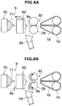
- the air-jet spinning device 9 moves away from the front roller pair 30 that has come to a stop (see FIG. 5B ). Even if the waste fibers 8a are not yet drawn out from the air-jet spinning device 9, by the movement of the air-jet spinning device 9 while the waste fibers 8a are gripped at one end by the front roller pair 30, the waste fibers 8a are drawn out from the air-jet spinning device 9. Further movement of the air-jet spinning device 9 away from the front roller pair 30 causes separation of the second holder 70 from the first holder 60 (see FIG. 6A ). In the present embodiment, the air-jet spinning device 9 is moved along the fiber traveling direction. However, the air-jet spinning device 9 can be moved in a perpendicular direction to the fiber traveling direction (in upward and downward directions in FIGS. 6A and 6B or toward front and back of the sheet surface).
- the front roller pair 30 rotates in the direction of rotation during spinning (hereinafter, "forward rotation").
- forward rotation the waste fibers 8a drawn out from the air-jet spinning device 9 are conveyed to the outside of the drafting device 7.
- the waste fibers 8a conveyed to the outside of the drafting device 7 are sucked and removed by the sucking and removing device 29.
- the air-jet spinning device 9 injects compressed air from the nozzle 63.
- the waste fibers 8a are drawn out from the air-jet spinning device 9 by the front roller pair 30.
- the compressed air injected from the nozzle 63 substantially thoroughly removes the waste fibers 8a left behind in the fiber guide 61, and the like.
- the air-jet spinning device 9 moves toward the front roller pair 30 (see FIG. 7A ). Thereafter, the front roller pair 30 and the other drafting roller pairs rotate forward to draft the sliver 15, and the air-jet spinning device 9 spins the fiber bundle 8 (see FIG. 7B ). With this action, the spinning is started.
- the spinning machine includes the drafting device 7, the air-jet spinning device 9, and the first driving section 31.
- the drafting device 7 includes the plural drafting roller pairs, including the front roller pair 30, that draft the fiber bundle 8.
- the air-jet spinning device 9 carries out spinning to twist the fiber bundle 8 drafted by the drafting device 7 to form the spun yarn 10.
- the first driving section 31 reverse-rotates (rotates in the second direction) the front roller pair 30 when the fiber bundle 8 is discontinuous between the drafting device 7 and the air-jet spinning device 9 before the start of spinning.
- the reverse-rotation of the front roller pair 30 enables the front roller pair 30 to grip and draw out the waste fibers 8a clogging the air-jet spinning device 9. Hence, even when the waste fibers 8a clog the air-jet spinning device 9 when the spinning has stopped, the waste fibers 8a are automatically removed and spinning is started, and thereby productivity can be enhanced.
- the air-jet spinning device 9 includes the fiber guide 61 with the fiber guiding opening 61a that guides the fiber bundle 8 into the air-jet spinning device 9.
- the fiber guide 61 is located near the front roller pair 30. Therefore, even if the waste fibers 8a are clogging the fiber guiding opening 61a, the waste fibers 8a can be easily drawn out from the air-jet spinning device 9.
- the first driving section 31 rotates the front roller pair 30 forward.
- the front roller pair 30 can convey the waste fibers 8a to the outside of the drafting device 7.
- the spinning machine includes the cylinder 81 that causes the air-jet spinning device 9 to move toward or away from the front roller pair 30. After the reverse rotation of the front roller pair 30, the cylinder 81 causes the air-jet spinning device 9 to move away from the front roller pair 30.
- the front roller pair 30 is rotated forward after it is reverse-rotated.
- the waste fibers 8a can be removed from the air-jet spinning device 9 by only reverse-rotating the front roller pair 30.
- the front roller 20 and the apron belt 18 are located away from each other by a longer distance, the waste fibers 8a that are drawn out cannot easily clog the apron belt 18, and hence the forward rotation of the front roller pair 30 can be omitted.
- movement of the air-jet spinning device 9 is realized by the swinging of the first arm 65 and the second arm 75.
- the movement of the air-jet spinning device 9, however, can be realized, for example, by moving along a rail in a parallel manner.
- the present invention is applied to the air-jet spinning device 9 that performs spinning with the nozzle 63 and the hollow guide shaft 71.
- the present invention can, however, be applied to air-jet spinning devices that perform air-jet spinning by other methods.
- the present invention can be applied to the air-jet spinning device disclosed in Patent Application No. 2011-38210 that performs air-jet spinning by the action of swirling air currents from two different directions.
- the unclogging process of the air-jet spinning device 9 is performed in all the spinning units 2, regardless of whether clogging has actually occurred.
- a sensor that detects clogging in the air-jet spinning device 9 can be arranged, and the above process can be performed only in the spinning unit 2 in which clogging has occurred.
- the rotation of the drafting roller pair (front roller pair 30) of each spinning unit 2 is controlled separately.
- spinning instead of performing the unclogging process, spinning can be first restarted, and the unclogging process can be performed only when the spinning fails to restart successively for a predetermined number of times, after which spinning can be restarted.
- the front roller pair 30 is reverse-rotated and thereafter the air-jet spinning device 9 is moved and the waste fibers 8a are removed by blowing air from the nozzle 63.
- the air-jet spinning device 9 can be moved first and the waste fibers 8a can be removed by blowing air from the nozzle 63, and thereafter the air-jet spinning device 9 can be moved back and the front roller pair 30 can be reverse-rotated to unclog the air-jet spinning device 9.
- the movement of the air-jet spinning device 9 can be omitted altogether and the front roller pair 30 can be reverse-rotated and thereafter rotated forward.
- the back roller 16, the third roller 17, and the middle roller 19 are driven by a single driving section (the second driving section 32).
- a separate driving section can be used to drive each drafting roller.
- the back roller 16 and the third roller 17 can be driven by a common driving section, and the middle roller 19 can be driven by a separate driving section.
- the guide needle 61b can be omitted, and the function of the guide needle 61b can be realized with the downstream end of the fiber guide 61.
- a configuration can be adopted in which a work carrier is arranged that is capable of moving among the spinning units 2 to perform yarn joining wherever required.
- a configuration can be adopted in which the yarn path from the drafting device 7 to the winding section 26 is linear.
- Another configuration can be adopted in which the yarn path runs from top to bottom in a height direction of the spinning machine.
- the spun yarn 10 formed by the air-jet spinning device 9 is wound by the winding section 26 to form the package 50.
- a configuration can be adopted in which a knitting machine, and the like, is arranged downstream of the air-jet spinning device 9.
- the spinning machine includes a drafting device, an air-jet spinning device, and a first driving member.
- the drafting device includes plural drafting roller pairs, including a front roller pair, and drafts a fiber bundle.
- the air-jet spinning device carries out spinning to twist the fiber bundle drafted by the drafting device to form a yarn.
- the first driving member rotates, when the fiber bundle is discontinuous between the drafting device and the air-jet spinning device before start of the spinning, the front roller pair in a second direction that is opposite to a first direction that is a rotational direction during the spinning.
- the fibers clogging the air-jet spinning device can be gripped by the front roller pair and drawn out. Hence, even when the fibers clog the air-jet spinning device when the spinning has stopped, the fibers clogging the air-jet spinning device are automatically removed and the spinning is started, and thereby productivity can be enhanced.
- the air-jet spinning device includes a fiber guide with a fiber guiding opening that guides the fiber bundle into the air-jet spinning device.
- the fiber guide is located near the front roller pair, even if the fibers clog the fiber guide opening, the fibers can be easily drawn out from the air-jet spinning device.
- the first driving section rotates the front roller pair in the first direction after the front roller pair is rotated in the second direction and before the spinning is started by the air-jet spinning device.
- the spinning machine further includes a second driving section that drives the drafting roller pairs other than the front roller pair.
- the front roller pair can be rotated independently of the other drafting roller pairs. Consequently, the front roller pair can be rotated while the back roller pair, and such like, is stopped.
- the spinning machine includes a moving member capable of moving the air-jet spinning device away from or toward the front roller pair.
- the moving member moves the air-jet spinning device away from the front roller pair after the first driving section rotates the front roller pair in the second direction.
- the air-jet spinning device includes a nozzle block and a hollow guide shaft.
- the nozzle block includes a nozzle through which the air that is to be injected into the spinning chamber for generating a swirling air current passes.
- the fiber bundle that is twisted by the swirling air current in the spinning chamber passes through the hollow guide shaft.
- the fibers left behind in the air-jet spinning device can be removed.
- the moving member causes the air-jet spinning device to move closer to the front roller pair before the first driving section rotates the front roller pair in the second direction.
- the fibers clogging the air-jet spinning device can be more reliably gripped and drawn out by the front roller pair.
- a rotation speed of the front roller pair in the second direction is slower than a rotation speed of the front roller pair in the first direction during the spinning.
- the fibers clogging the air-jet spinning device can be drawn out at a speed that does not cause the fibers to break.
- the spinning machine further includes a sucking and removing device that sucks and removes the fibers drawn out by the rotation of the front roller pair in the second direction.
- the fibers drawn out from the air-jet spinning device can be prevented from adhering to other members.
- the spinning machine includes plural spinning units.
- Each of the spinning units includes the plural drafting roller pairs, the air-jet spinning device, and the first driving member.
- the front roller pair can be rotated in the second direction only in the spinning unit in which there is a possibility of the fibers clogging the air-jet spinning device.
- a fiber removal method draws out fibers clogging the air-jet spinning device by causing the front roller pair of the drafting device to rotate, when the fiber bundle between the drafting device and the air-jet spinning device is discontinuous before the start of spinning, in the direction opposite to the rotational direction during the spinning.
- the fibers clogging the air-jet spinning device can be gripped and drawn out by the front roller pair. Hence, even when the fibers clog the air-jet spinning device when the spinning has stopped, the fibers clogging the air-jet spinning device are automatically removed and the spinning is started, and thereby productivity can be enhanced.
Landscapes
- Engineering & Computer Science (AREA)
- Mechanical Engineering (AREA)
- Textile Engineering (AREA)
- Spinning Or Twisting Of Yarns (AREA)
Claims (10)
- Spinnmaschine umfassend:eine Streckvorrichtung (7), die mehrere Streckrollenpaare einschließlich eines vorderen Rollenpaars (30) einschließt und angepasst ist, um ein Faserbündel (15) zu ziehen;eine Luftspinnvorrichtung (9), die angepasst ist, ein Spinnen durchzuführen, um das von der Streckvorrichtung (7) gezogene Faserbündel (8) zu verdrehen, um ein Garn (10) zu bilden; undeinen ersten Antriebsabschnitt (31), der angeordnet ist, um, wenn das Faserbündel (8) zwischen der Streckvorrichtung (7) und der Luftspinnvorrichtung (9) vor Beginn des Spinnens nicht kontinuierlich ist, das vordere Rollenpaar (30) in einer zweiten Richtung zu drehen, die entgegengesetzt zu einer ersten Richtung ist, die eine Drehrichtung während des Spinnens ist,dadurch gekennzeichnet,dass sie weiter ein Bewegungselement (81) umfasst, das in der Lage ist, die Luftspinnvorrichtung (9) von dem vorderen Rollenpaar (30) weg oder zu diesem hin zu bewegen, wobei das Bewegungselement (81) angeordnet ist, um die Luftspinnvorrichtung (9) von dem vorderen Rollenpaar (30) weg zu bewegen, nachdem der erste Antriebsabschnitt (31) begonnen hat, das vordere Rollenpaar (30) in der zweiten Richtung zu drehen,wobei das Bewegungselement (81) angeordnet ist, um zu bewirken, dass sich die Luftspinnvorrichtung (9) näher zu dem vorderen Rollenpaar (30) bewegt, bevor der erste Antriebsabschnitt (31) das vordere Rollenpaar (30) in der zweiten Richtung dreht.
- Spinnmaschine nach Anspruch 1, wobei die Luftspinnvorrichtung (9) eine Faserführung (61) mit einer Faserführungsöffnung (61a) einschließt, die angepasst ist, um das Faserbündel (8) in die Luftspinnvorrichtung (9) zu führen.
- Spinnmaschine nach Anspruch 1 oder Anspruch 2, wobei der erste Antriebsabschnitt (31) angeordnet ist, um das vordere Rollenpaar (30) in der ersten Richtung zu drehen, nachdem das vordere Rollenpaar (30) in der zweiten Richtung gedreht worden ist und bevor das Drehen durch die Luftspinnvorrichtung (9) begonnen wird.
- Spinnmaschine nach einem der Ansprüche 1 bis 3, weiter einen zweiten Antriebsabschnitt (32) umfassend, der angepasst ist, um die anderen Streckrollenpaare als das vordere Rollenpaar (30) anzutreiben.
- Spinnmaschine nach einem der vorstehenden Ansprüche, wobei die Luftspinnvorrichtung (9) Folgendes einschließt
einen Düsenblock (60), der eine Düse (63) aufweist, durch die zu injizierende Luft in eine Spinnkammer (62) zum Erzeugen eines Wirbelluftstroms hindurchströmen kann; und
eine hohle Führungswelle (71), durch die das in der Spinnkammer (62) durch den Wirbelluftstrom verdrehte Faserbündel (8) hindurchströmen kann,
wobei die Luft von der Düse (63) injiziert wird, nachdem das Bewegungselement (81) bewirkt hat, dass sich die Luftspinnvorrichtung (9) von dem vorderen Rollenpaar (30) wegbewegt und der Düsenblock (60) und die hohle Führungswelle (71) sich voneinander trennen. - Spinnmaschine nach einem der Ansprüche 1 bis 5, wobei eine Drehgeschwindigkeit des vorderen Rollenpaars (30) in der zweiten Richtung eingestellt wird, um während des Spinnens langsamer als eine Drehgeschwindigkeit des vorderen Rollenpaars (30) in der ersten Richtung zu sein.
- Spinnmaschine nach einem der Ansprüche 1 bis 6, weiter umfassend eine Saug- und Entfernungsvorrichtung (29), die angepasst ist, um durch die Drehung des vorderen Rollenpaars (30) in der zweiten Richtung herausgezogene Fasern anzusaugen und zu entfernen.
- Spinnmaschine nach einem der Ansprüche 1 bis 7, umfassend mehrere Spinneinheiten (2), wobei jede Spinneinheit (2) mehrere Streckrollenpaare, die Luftspinnvorrichtung (9) und den ersten Antriebsabschnitt (31) einschließt.
- Spinnmaschine nach einem der vorstehenden Ansprüche, wobei das Bewegungselement (81) angeordnet ist, um die Luftspinnvorrichtung (9) von dem vorderen Rollenpaar (30) weg zu bewegen, nachdem der erste Antriebsabschnitt (31) die Drehung des vorderen Rollenpaars (30) in der zweiten Richtung gestoppt hat.
- Faserentfernungsverfahren zum Ausziehen von Fasern, die eine Luftspinnvorrichtung (9) verstopfen, indem ein vorderes Rollenpaar (30) einer Streckvorrichtung (7) in Drehung versetzt wird, wenn ein Faserbündel (8) zwischen der Streckvorrichtung (7) und der Luftspinnvorrichtung (9) vor dem Spinnbeginn in einer Richtung entgegengesetzt zu einer Drehrichtung während des Spinnens nicht kontinuierlich ist, wobei das Verfahren weiter umfasst, dass die Luftspinnvorrichtung (9) vor dem Drehen des vorderen Rollenpaars in einer Richtung entgegengesetzt zu einer Drehrichtung während des Drehens näher zu dem vorderen Rollenpaar (30) bewegt wird und dass die Luftspinnvorrichtung (9) von dem vorderen Rollenpaar (30) wegbewegt wird, nachdem die Drehung des vorderen Rollenpaars (30) in der Richtung entgegengesetzt zu der Drehrichtung während des Drehens begonnen hat.
Applications Claiming Priority (1)
| Application Number | Priority Date | Filing Date | Title |
|---|---|---|---|
| JP2014141876A JP2016017253A (ja) | 2014-07-10 | 2014-07-10 | 紡績機及び紡績方法 |
Publications (3)
| Publication Number | Publication Date |
|---|---|
| EP2966199A2 EP2966199A2 (de) | 2016-01-13 |
| EP2966199A3 EP2966199A3 (de) | 2016-03-02 |
| EP2966199B1 true EP2966199B1 (de) | 2018-12-05 |
Family
ID=53298125
Family Applications (1)
| Application Number | Title | Priority Date | Filing Date |
|---|---|---|---|
| EP15167295.3A Not-in-force EP2966199B1 (de) | 2014-07-10 | 2015-05-12 | Spinnmaschine und spinnverfahren |
Country Status (3)
| Country | Link |
|---|---|
| EP (1) | EP2966199B1 (de) |
| JP (1) | JP2016017253A (de) |
| CN (1) | CN105274667B (de) |
Families Citing this family (1)
| Publication number | Priority date | Publication date | Assignee | Title |
|---|---|---|---|---|
| JP2018065638A (ja) * | 2016-10-18 | 2018-04-26 | 村田機械株式会社 | 糸巻取装置及びパッケージ減速方法 |
Family Cites Families (6)
| Publication number | Priority date | Publication date | Assignee | Title |
|---|---|---|---|---|
| JP3196706B2 (ja) * | 1997-09-22 | 2001-08-06 | 村田機械株式会社 | 紡績機の運転方法 |
| EP1207225B2 (de) * | 2000-11-16 | 2011-08-31 | Murata Kikai Kabushiki Kaisha | Spinnvorrichtung |
| JP3956689B2 (ja) | 2001-12-19 | 2007-08-08 | 村田機械株式会社 | 紡績装置 |
| DE102004047582A1 (de) * | 2004-09-22 | 2006-04-06 | Wilhelm Stahlecker Gmbh | Verfahren und Vorrichtung zum Vorbereiten eines Ansetzvorganges an einer Luftdüsenspinnvorrichtung |
| JP2011038210A (ja) | 2009-08-11 | 2011-02-24 | Murata Machinery Ltd | 空気紡績装置及びこの空気紡績装置を備える紡績機 |
| JP2013067895A (ja) * | 2011-09-21 | 2013-04-18 | Murata Mach Ltd | 紡績ユニット及び紡績機 |
-
2014
- 2014-07-10 JP JP2014141876A patent/JP2016017253A/ja active Pending
-
2015
- 2015-05-12 EP EP15167295.3A patent/EP2966199B1/de not_active Not-in-force
- 2015-06-16 CN CN201510333414.0A patent/CN105274667B/zh active Active
Non-Patent Citations (1)
| Title |
|---|
| None * |
Also Published As
| Publication number | Publication date |
|---|---|
| JP2016017253A (ja) | 2016-02-01 |
| EP2966199A2 (de) | 2016-01-13 |
| CN105274667B (zh) | 2019-07-26 |
| EP2966199A3 (de) | 2016-03-02 |
| CN105274667A (zh) | 2016-01-27 |
Similar Documents
| Publication | Publication Date | Title |
|---|---|---|
| CN101994176B (zh) | 纺纱机械 | |
| EP2573017B1 (de) | Garnwickeleinheit, Garnwickelvorrichtung und Spinnmaschine | |
| EP2361867A2 (de) | Garnwicklungsmaschine | |
| EP2727870A2 (de) | Garnwickelmaschine und Garnwickelverfahren | |
| EP3072840B1 (de) | Garnwickelmaschine und garnwickelverfahren | |
| CN109385703B (zh) | 气流纺纱机 | |
| JP2013067475A (ja) | 糸巻取機及び糸巻取ユニット | |
| EP2573030B1 (de) | Garnwickelmaschine | |
| EP2966200B1 (de) | Spinnmaschine und spinnverfahren | |
| CN105253703B (zh) | 纱线卷取机以及纱线卷取方法 | |
| JP2007284812A (ja) | 糸継ぎ装置および糸継ぎ方法 | |
| EP2949793B1 (de) | Spinnmaschine und spinnverfahren | |
| CN110158207B (zh) | 空气纺纱机和空气纺纱方法 | |
| EP1726695B1 (de) | Verfahren und Vorrichtung zur Herstellung eines Kerngarns | |
| EP2749517A1 (de) | Spinnmaschine | |
| EP3025996B1 (de) | Garnwickelmaschine mit einer garnverbindungsvorrichtung, und garnverbindungsverfahren | |
| EP2985371B1 (de) | Spinnmaschine | |
| EP2966199B1 (de) | Spinnmaschine und spinnverfahren | |
| CN106939451B (zh) | 纺纱机械 | |
| CN211171024U (zh) | 一种纱线的纺纱机构 | |
| CN108286093B (zh) | 一种纺纱机 | |
| CN106167201A (zh) | 纱线卷取机 | |
| JP2017036524A (ja) | 空気紡績装置及びキャップ部材 | |
| CN113774526A (zh) | 气流纺纱机 | |
| CN114575005A (zh) | 纺纱机和纺纱方法 |
Legal Events
| Date | Code | Title | Description |
|---|---|---|---|
| PUAI | Public reference made under article 153(3) epc to a published international application that has entered the european phase |
Free format text: ORIGINAL CODE: 0009012 |
|
| AK | Designated contracting states |
Kind code of ref document: A2 Designated state(s): AL AT BE BG CH CY CZ DE DK EE ES FI FR GB GR HR HU IE IS IT LI LT LU LV MC MK MT NL NO PL PT RO RS SE SI SK SM TR |
|
| AX | Request for extension of the european patent |
Extension state: BA ME |
|
| PUAL | Search report despatched |
Free format text: ORIGINAL CODE: 0009013 |
|
| AK | Designated contracting states |
Kind code of ref document: A3 Designated state(s): AL AT BE BG CH CY CZ DE DK EE ES FI FR GB GR HR HU IE IS IT LI LT LU LV MC MK MT NL NO PL PT RO RS SE SI SK SM TR |
|
| AX | Request for extension of the european patent |
Extension state: BA ME |
|
| RIC1 | Information provided on ipc code assigned before grant |
Ipc: D01H 1/115 20060101AFI20160127BHEP Ipc: D01H 11/00 20060101ALI20160127BHEP Ipc: D01H 5/66 20060101ALI20160127BHEP Ipc: D01H 1/22 20060101ALI20160127BHEP |
|
| 17P | Request for examination filed |
Effective date: 20160804 |
|
| RBV | Designated contracting states (corrected) |
Designated state(s): AL AT BE BG CH CY CZ DE DK EE ES FI FR GB GR HR HU IE IS IT LI LT LU LV MC MK MT NL NO PL PT RO RS SE SI SK SM TR |
|
| GRAP | Despatch of communication of intention to grant a patent |
Free format text: ORIGINAL CODE: EPIDOSNIGR1 |
|
| STAA | Information on the status of an ep patent application or granted ep patent |
Free format text: STATUS: GRANT OF PATENT IS INTENDED |
|
| INTG | Intention to grant announced |
Effective date: 20180727 |
|
| GRAS | Grant fee paid |
Free format text: ORIGINAL CODE: EPIDOSNIGR3 |
|
| GRAA | (expected) grant |
Free format text: ORIGINAL CODE: 0009210 |
|
| GRAA | (expected) grant |
Free format text: ORIGINAL CODE: 0009210 |
|
| STAA | Information on the status of an ep patent application or granted ep patent |
Free format text: STATUS: THE PATENT HAS BEEN GRANTED |
|
| AK | Designated contracting states |
Kind code of ref document: B1 Designated state(s): AL AT BE BG CH CY CZ DE DK EE ES FI FR GB GR HR HU IE IS IT LI LT LU LV MC MK MT NL NO PL PT RO RS SE SI SK SM TR |
|
| REG | Reference to a national code |
Ref country code: GB Ref legal event code: FG4D |
|
| REG | Reference to a national code |
Ref country code: CH Ref legal event code: EP |
|
| REG | Reference to a national code |
Ref country code: AT Ref legal event code: REF Ref document number: 1073192 Country of ref document: AT Kind code of ref document: T Effective date: 20181215 |
|
| REG | Reference to a national code |
Ref country code: DE Ref legal event code: R096 Ref document number: 602015020715 Country of ref document: DE |
|
| REG | Reference to a national code |
Ref country code: IE Ref legal event code: FG4D |
|
| REG | Reference to a national code |
Ref country code: NL Ref legal event code: MP Effective date: 20181205 |
|
| REG | Reference to a national code |
Ref country code: AT Ref legal event code: MK05 Ref document number: 1073192 Country of ref document: AT Kind code of ref document: T Effective date: 20181205 |
|
| REG | Reference to a national code |
Ref country code: LT Ref legal event code: MG4D |
|
| PG25 | Lapsed in a contracting state [announced via postgrant information from national office to epo] |
Ref country code: ES Free format text: LAPSE BECAUSE OF FAILURE TO SUBMIT A TRANSLATION OF THE DESCRIPTION OR TO PAY THE FEE WITHIN THE PRESCRIBED TIME-LIMIT Effective date: 20181205 Ref country code: LT Free format text: LAPSE BECAUSE OF FAILURE TO SUBMIT A TRANSLATION OF THE DESCRIPTION OR TO PAY THE FEE WITHIN THE PRESCRIBED TIME-LIMIT Effective date: 20181205 Ref country code: HR Free format text: LAPSE BECAUSE OF FAILURE TO SUBMIT A TRANSLATION OF THE DESCRIPTION OR TO PAY THE FEE WITHIN THE PRESCRIBED TIME-LIMIT Effective date: 20181205 Ref country code: BG Free format text: LAPSE BECAUSE OF FAILURE TO SUBMIT A TRANSLATION OF THE DESCRIPTION OR TO PAY THE FEE WITHIN THE PRESCRIBED TIME-LIMIT Effective date: 20190305 Ref country code: AT Free format text: LAPSE BECAUSE OF FAILURE TO SUBMIT A TRANSLATION OF THE DESCRIPTION OR TO PAY THE FEE WITHIN THE PRESCRIBED TIME-LIMIT Effective date: 20181205 Ref country code: LV Free format text: LAPSE BECAUSE OF FAILURE TO SUBMIT A TRANSLATION OF THE DESCRIPTION OR TO PAY THE FEE WITHIN THE PRESCRIBED TIME-LIMIT Effective date: 20181205 Ref country code: NO Free format text: LAPSE BECAUSE OF FAILURE TO SUBMIT A TRANSLATION OF THE DESCRIPTION OR TO PAY THE FEE WITHIN THE PRESCRIBED TIME-LIMIT Effective date: 20190305 Ref country code: FI Free format text: LAPSE BECAUSE OF FAILURE TO SUBMIT A TRANSLATION OF THE DESCRIPTION OR TO PAY THE FEE WITHIN THE PRESCRIBED TIME-LIMIT Effective date: 20181205 |
|
| PG25 | Lapsed in a contracting state [announced via postgrant information from national office to epo] |
Ref country code: AL Free format text: LAPSE BECAUSE OF FAILURE TO SUBMIT A TRANSLATION OF THE DESCRIPTION OR TO PAY THE FEE WITHIN THE PRESCRIBED TIME-LIMIT Effective date: 20181205 Ref country code: SE Free format text: LAPSE BECAUSE OF FAILURE TO SUBMIT A TRANSLATION OF THE DESCRIPTION OR TO PAY THE FEE WITHIN THE PRESCRIBED TIME-LIMIT Effective date: 20181205 Ref country code: RS Free format text: LAPSE BECAUSE OF FAILURE TO SUBMIT A TRANSLATION OF THE DESCRIPTION OR TO PAY THE FEE WITHIN THE PRESCRIBED TIME-LIMIT Effective date: 20181205 Ref country code: GR Free format text: LAPSE BECAUSE OF FAILURE TO SUBMIT A TRANSLATION OF THE DESCRIPTION OR TO PAY THE FEE WITHIN THE PRESCRIBED TIME-LIMIT Effective date: 20190306 |
|
| PG25 | Lapsed in a contracting state [announced via postgrant information from national office to epo] |
Ref country code: NL Free format text: LAPSE BECAUSE OF FAILURE TO SUBMIT A TRANSLATION OF THE DESCRIPTION OR TO PAY THE FEE WITHIN THE PRESCRIBED TIME-LIMIT Effective date: 20181205 |
|
| PG25 | Lapsed in a contracting state [announced via postgrant information from national office to epo] |
Ref country code: PT Free format text: LAPSE BECAUSE OF FAILURE TO SUBMIT A TRANSLATION OF THE DESCRIPTION OR TO PAY THE FEE WITHIN THE PRESCRIBED TIME-LIMIT Effective date: 20190405 Ref country code: IT Free format text: LAPSE BECAUSE OF FAILURE TO SUBMIT A TRANSLATION OF THE DESCRIPTION OR TO PAY THE FEE WITHIN THE PRESCRIBED TIME-LIMIT Effective date: 20181205 Ref country code: PL Free format text: LAPSE BECAUSE OF FAILURE TO SUBMIT A TRANSLATION OF THE DESCRIPTION OR TO PAY THE FEE WITHIN THE PRESCRIBED TIME-LIMIT Effective date: 20181205 |
|
| PGFP | Annual fee paid to national office [announced via postgrant information from national office to epo] |
Ref country code: CZ Payment date: 20190502 Year of fee payment: 5 Ref country code: DE Payment date: 20190521 Year of fee payment: 5 |
|
| PG25 | Lapsed in a contracting state [announced via postgrant information from national office to epo] |
Ref country code: SK Free format text: LAPSE BECAUSE OF FAILURE TO SUBMIT A TRANSLATION OF THE DESCRIPTION OR TO PAY THE FEE WITHIN THE PRESCRIBED TIME-LIMIT Effective date: 20181205 Ref country code: RO Free format text: LAPSE BECAUSE OF FAILURE TO SUBMIT A TRANSLATION OF THE DESCRIPTION OR TO PAY THE FEE WITHIN THE PRESCRIBED TIME-LIMIT Effective date: 20181205 Ref country code: IS Free format text: LAPSE BECAUSE OF FAILURE TO SUBMIT A TRANSLATION OF THE DESCRIPTION OR TO PAY THE FEE WITHIN THE PRESCRIBED TIME-LIMIT Effective date: 20190405 Ref country code: EE Free format text: LAPSE BECAUSE OF FAILURE TO SUBMIT A TRANSLATION OF THE DESCRIPTION OR TO PAY THE FEE WITHIN THE PRESCRIBED TIME-LIMIT Effective date: 20181205 Ref country code: SM Free format text: LAPSE BECAUSE OF FAILURE TO SUBMIT A TRANSLATION OF THE DESCRIPTION OR TO PAY THE FEE WITHIN THE PRESCRIBED TIME-LIMIT Effective date: 20181205 |
|
| REG | Reference to a national code |
Ref country code: DE Ref legal event code: R097 Ref document number: 602015020715 Country of ref document: DE |
|
| PGFP | Annual fee paid to national office [announced via postgrant information from national office to epo] |
Ref country code: CH Payment date: 20190521 Year of fee payment: 5 |
|
| PLBE | No opposition filed within time limit |
Free format text: ORIGINAL CODE: 0009261 |
|
| STAA | Information on the status of an ep patent application or granted ep patent |
Free format text: STATUS: NO OPPOSITION FILED WITHIN TIME LIMIT |
|
| PG25 | Lapsed in a contracting state [announced via postgrant information from national office to epo] |
Ref country code: DK Free format text: LAPSE BECAUSE OF FAILURE TO SUBMIT A TRANSLATION OF THE DESCRIPTION OR TO PAY THE FEE WITHIN THE PRESCRIBED TIME-LIMIT Effective date: 20181205 Ref country code: SI Free format text: LAPSE BECAUSE OF FAILURE TO SUBMIT A TRANSLATION OF THE DESCRIPTION OR TO PAY THE FEE WITHIN THE PRESCRIBED TIME-LIMIT Effective date: 20181205 |
|
| 26N | No opposition filed |
Effective date: 20190906 |
|
| GBPC | Gb: european patent ceased through non-payment of renewal fee |
Effective date: 20190512 |
|
| PG25 | Lapsed in a contracting state [announced via postgrant information from national office to epo] |
Ref country code: MC Free format text: LAPSE BECAUSE OF FAILURE TO SUBMIT A TRANSLATION OF THE DESCRIPTION OR TO PAY THE FEE WITHIN THE PRESCRIBED TIME-LIMIT Effective date: 20181205 |
|
| REG | Reference to a national code |
Ref country code: BE Ref legal event code: MM Effective date: 20190531 |
|
| PG25 | Lapsed in a contracting state [announced via postgrant information from national office to epo] |
Ref country code: LU Free format text: LAPSE BECAUSE OF NON-PAYMENT OF DUE FEES Effective date: 20190512 |
|
| PG25 | Lapsed in a contracting state [announced via postgrant information from national office to epo] |
Ref country code: TR Free format text: LAPSE BECAUSE OF FAILURE TO SUBMIT A TRANSLATION OF THE DESCRIPTION OR TO PAY THE FEE WITHIN THE PRESCRIBED TIME-LIMIT Effective date: 20181205 |
|
| PG25 | Lapsed in a contracting state [announced via postgrant information from national office to epo] |
Ref country code: GB Free format text: LAPSE BECAUSE OF NON-PAYMENT OF DUE FEES Effective date: 20190512 Ref country code: IE Free format text: LAPSE BECAUSE OF NON-PAYMENT OF DUE FEES Effective date: 20190512 |
|
| PG25 | Lapsed in a contracting state [announced via postgrant information from national office to epo] |
Ref country code: BE Free format text: LAPSE BECAUSE OF NON-PAYMENT OF DUE FEES Effective date: 20190531 |
|
| PG25 | Lapsed in a contracting state [announced via postgrant information from national office to epo] |
Ref country code: FR Free format text: LAPSE BECAUSE OF NON-PAYMENT OF DUE FEES Effective date: 20190531 |
|
| REG | Reference to a national code |
Ref country code: DE Ref legal event code: R119 Ref document number: 602015020715 Country of ref document: DE |
|
| PG25 | Lapsed in a contracting state [announced via postgrant information from national office to epo] |
Ref country code: LI Free format text: LAPSE BECAUSE OF NON-PAYMENT OF DUE FEES Effective date: 20200531 Ref country code: CZ Free format text: LAPSE BECAUSE OF NON-PAYMENT OF DUE FEES Effective date: 20200512 Ref country code: CH Free format text: LAPSE BECAUSE OF NON-PAYMENT OF DUE FEES Effective date: 20200531 |
|
| PG25 | Lapsed in a contracting state [announced via postgrant information from national office to epo] |
Ref country code: DE Free format text: LAPSE BECAUSE OF NON-PAYMENT OF DUE FEES Effective date: 20201201 Ref country code: CY Free format text: LAPSE BECAUSE OF FAILURE TO SUBMIT A TRANSLATION OF THE DESCRIPTION OR TO PAY THE FEE WITHIN THE PRESCRIBED TIME-LIMIT Effective date: 20181205 |
|
| PG25 | Lapsed in a contracting state [announced via postgrant information from national office to epo] |
Ref country code: MT Free format text: LAPSE BECAUSE OF FAILURE TO SUBMIT A TRANSLATION OF THE DESCRIPTION OR TO PAY THE FEE WITHIN THE PRESCRIBED TIME-LIMIT Effective date: 20181205 Ref country code: HU Free format text: LAPSE BECAUSE OF FAILURE TO SUBMIT A TRANSLATION OF THE DESCRIPTION OR TO PAY THE FEE WITHIN THE PRESCRIBED TIME-LIMIT; INVALID AB INITIO Effective date: 20150512 |
|
| PG25 | Lapsed in a contracting state [announced via postgrant information from national office to epo] |
Ref country code: MK Free format text: LAPSE BECAUSE OF FAILURE TO SUBMIT A TRANSLATION OF THE DESCRIPTION OR TO PAY THE FEE WITHIN THE PRESCRIBED TIME-LIMIT Effective date: 20181205 |