EP2572916A2 - Dispositif de commande de transmission de puissance pour véhicule - Google Patents
Dispositif de commande de transmission de puissance pour véhicule Download PDFInfo
- Publication number
- EP2572916A2 EP2572916A2 EP12184944A EP12184944A EP2572916A2 EP 2572916 A2 EP2572916 A2 EP 2572916A2 EP 12184944 A EP12184944 A EP 12184944A EP 12184944 A EP12184944 A EP 12184944A EP 2572916 A2 EP2572916 A2 EP 2572916A2
- Authority
- EP
- European Patent Office
- Prior art keywords
- vehicle
- speed
- gear position
- state
- output shaft
- Prior art date
- Legal status (The legal status is an assumption and is not a legal conclusion. Google has not performed a legal analysis and makes no representation as to the accuracy of the status listed.)
- Granted
Links
- 230000005540 biological transmission Effects 0.000 title claims abstract description 42
- 230000008859 change Effects 0.000 claims description 43
- 230000009467 reduction Effects 0.000 claims description 14
- 238000002485 combustion reaction Methods 0.000 claims description 11
- 230000001133 acceleration Effects 0.000 claims description 4
- 230000009471 action Effects 0.000 description 38
- 230000007423 decrease Effects 0.000 description 8
- 239000000446 fuel Substances 0.000 description 3
- 102100031102 C-C motif chemokine 4 Human genes 0.000 description 2
- 102100026620 E3 ubiquitin ligase TRAF3IP2 Human genes 0.000 description 2
- 101710140859 E3 ubiquitin ligase TRAF3IP2 Proteins 0.000 description 2
- 101000777470 Mus musculus C-C motif chemokine 4 Proteins 0.000 description 2
- 238000010586 diagram Methods 0.000 description 2
- 230000004044 response Effects 0.000 description 2
- 230000003247 decreasing effect Effects 0.000 description 1
- 230000005764 inhibitory process Effects 0.000 description 1
- 238000002347 injection Methods 0.000 description 1
- 239000007924 injection Substances 0.000 description 1
- 230000004048 modification Effects 0.000 description 1
- 238000012986 modification Methods 0.000 description 1
- 230000007935 neutral effect Effects 0.000 description 1
- 230000008929 regeneration Effects 0.000 description 1
- 238000011069 regeneration method Methods 0.000 description 1
- 230000000452 restraining effect Effects 0.000 description 1
- 230000001360 synchronised effect Effects 0.000 description 1
- 230000007704 transition Effects 0.000 description 1
Images


Classifications
-
- B—PERFORMING OPERATIONS; TRANSPORTING
- B60—VEHICLES IN GENERAL
- B60W—CONJOINT CONTROL OF VEHICLE SUB-UNITS OF DIFFERENT TYPE OR DIFFERENT FUNCTION; CONTROL SYSTEMS SPECIALLY ADAPTED FOR HYBRID VEHICLES; ROAD VEHICLE DRIVE CONTROL SYSTEMS FOR PURPOSES NOT RELATED TO THE CONTROL OF A PARTICULAR SUB-UNIT
- B60W10/00—Conjoint control of vehicle sub-units of different type or different function
- B60W10/10—Conjoint control of vehicle sub-units of different type or different function including control of change-speed gearings
-
- B—PERFORMING OPERATIONS; TRANSPORTING
- B60—VEHICLES IN GENERAL
- B60K—ARRANGEMENT OR MOUNTING OF PROPULSION UNITS OR OF TRANSMISSIONS IN VEHICLES; ARRANGEMENT OR MOUNTING OF PLURAL DIVERSE PRIME-MOVERS IN VEHICLES; AUXILIARY DRIVES FOR VEHICLES; INSTRUMENTATION OR DASHBOARDS FOR VEHICLES; ARRANGEMENTS IN CONNECTION WITH COOLING, AIR INTAKE, GAS EXHAUST OR FUEL SUPPLY OF PROPULSION UNITS IN VEHICLES
- B60K6/00—Arrangement or mounting of plural diverse prime-movers for mutual or common propulsion, e.g. hybrid propulsion systems comprising electric motors and internal combustion engines ; Control systems therefor, i.e. systems controlling two or more prime movers, or controlling one of these prime movers and any of the transmission, drive or drive units Informative references: mechanical gearings with secondary electric drive F16H3/72; arrangements for handling mechanical energy structurally associated with the dynamo-electric machine H02K7/00; machines comprising structurally interrelated motor and generator parts H02K51/00; dynamo-electric machines not otherwise provided for in H02K see H02K99/00
- B60K6/20—Arrangement or mounting of plural diverse prime-movers for mutual or common propulsion, e.g. hybrid propulsion systems comprising electric motors and internal combustion engines ; Control systems therefor, i.e. systems controlling two or more prime movers, or controlling one of these prime movers and any of the transmission, drive or drive units Informative references: mechanical gearings with secondary electric drive F16H3/72; arrangements for handling mechanical energy structurally associated with the dynamo-electric machine H02K7/00; machines comprising structurally interrelated motor and generator parts H02K51/00; dynamo-electric machines not otherwise provided for in H02K see H02K99/00 the prime-movers consisting of electric motors and internal combustion engines, e.g. HEVs
- B60K6/42—Arrangement or mounting of plural diverse prime-movers for mutual or common propulsion, e.g. hybrid propulsion systems comprising electric motors and internal combustion engines ; Control systems therefor, i.e. systems controlling two or more prime movers, or controlling one of these prime movers and any of the transmission, drive or drive units Informative references: mechanical gearings with secondary electric drive F16H3/72; arrangements for handling mechanical energy structurally associated with the dynamo-electric machine H02K7/00; machines comprising structurally interrelated motor and generator parts H02K51/00; dynamo-electric machines not otherwise provided for in H02K see H02K99/00 the prime-movers consisting of electric motors and internal combustion engines, e.g. HEVs characterised by the architecture of the hybrid electric vehicle
- B60K6/48—Parallel type
-
- B—PERFORMING OPERATIONS; TRANSPORTING
- B60—VEHICLES IN GENERAL
- B60W—CONJOINT CONTROL OF VEHICLE SUB-UNITS OF DIFFERENT TYPE OR DIFFERENT FUNCTION; CONTROL SYSTEMS SPECIALLY ADAPTED FOR HYBRID VEHICLES; ROAD VEHICLE DRIVE CONTROL SYSTEMS FOR PURPOSES NOT RELATED TO THE CONTROL OF A PARTICULAR SUB-UNIT
- B60W10/00—Conjoint control of vehicle sub-units of different type or different function
- B60W10/02—Conjoint control of vehicle sub-units of different type or different function including control of driveline clutches
-
- B—PERFORMING OPERATIONS; TRANSPORTING
- B60—VEHICLES IN GENERAL
- B60W—CONJOINT CONTROL OF VEHICLE SUB-UNITS OF DIFFERENT TYPE OR DIFFERENT FUNCTION; CONTROL SYSTEMS SPECIALLY ADAPTED FOR HYBRID VEHICLES; ROAD VEHICLE DRIVE CONTROL SYSTEMS FOR PURPOSES NOT RELATED TO THE CONTROL OF A PARTICULAR SUB-UNIT
- B60W10/00—Conjoint control of vehicle sub-units of different type or different function
- B60W10/10—Conjoint control of vehicle sub-units of different type or different function including control of change-speed gearings
- B60W10/11—Stepped gearings
-
- B—PERFORMING OPERATIONS; TRANSPORTING
- B60—VEHICLES IN GENERAL
- B60W—CONJOINT CONTROL OF VEHICLE SUB-UNITS OF DIFFERENT TYPE OR DIFFERENT FUNCTION; CONTROL SYSTEMS SPECIALLY ADAPTED FOR HYBRID VEHICLES; ROAD VEHICLE DRIVE CONTROL SYSTEMS FOR PURPOSES NOT RELATED TO THE CONTROL OF A PARTICULAR SUB-UNIT
- B60W20/00—Control systems specially adapted for hybrid vehicles
- B60W20/30—Control strategies involving selection of transmission gear ratio
-
- B—PERFORMING OPERATIONS; TRANSPORTING
- B60—VEHICLES IN GENERAL
- B60W—CONJOINT CONTROL OF VEHICLE SUB-UNITS OF DIFFERENT TYPE OR DIFFERENT FUNCTION; CONTROL SYSTEMS SPECIALLY ADAPTED FOR HYBRID VEHICLES; ROAD VEHICLE DRIVE CONTROL SYSTEMS FOR PURPOSES NOT RELATED TO THE CONTROL OF A PARTICULAR SUB-UNIT
- B60W30/00—Purposes of road vehicle drive control systems not related to the control of a particular sub-unit, e.g. of systems using conjoint control of vehicle sub-units
- B60W30/18—Propelling the vehicle
- B60W30/18009—Propelling the vehicle related to particular drive situations
- B60W30/18072—Coasting
-
- B—PERFORMING OPERATIONS; TRANSPORTING
- B60—VEHICLES IN GENERAL
- B60K—ARRANGEMENT OR MOUNTING OF PROPULSION UNITS OR OF TRANSMISSIONS IN VEHICLES; ARRANGEMENT OR MOUNTING OF PLURAL DIVERSE PRIME-MOVERS IN VEHICLES; AUXILIARY DRIVES FOR VEHICLES; INSTRUMENTATION OR DASHBOARDS FOR VEHICLES; ARRANGEMENTS IN CONNECTION WITH COOLING, AIR INTAKE, GAS EXHAUST OR FUEL SUPPLY OF PROPULSION UNITS IN VEHICLES
- B60K6/00—Arrangement or mounting of plural diverse prime-movers for mutual or common propulsion, e.g. hybrid propulsion systems comprising electric motors and internal combustion engines ; Control systems therefor, i.e. systems controlling two or more prime movers, or controlling one of these prime movers and any of the transmission, drive or drive units Informative references: mechanical gearings with secondary electric drive F16H3/72; arrangements for handling mechanical energy structurally associated with the dynamo-electric machine H02K7/00; machines comprising structurally interrelated motor and generator parts H02K51/00; dynamo-electric machines not otherwise provided for in H02K see H02K99/00
- B60K6/20—Arrangement or mounting of plural diverse prime-movers for mutual or common propulsion, e.g. hybrid propulsion systems comprising electric motors and internal combustion engines ; Control systems therefor, i.e. systems controlling two or more prime movers, or controlling one of these prime movers and any of the transmission, drive or drive units Informative references: mechanical gearings with secondary electric drive F16H3/72; arrangements for handling mechanical energy structurally associated with the dynamo-electric machine H02K7/00; machines comprising structurally interrelated motor and generator parts H02K51/00; dynamo-electric machines not otherwise provided for in H02K see H02K99/00 the prime-movers consisting of electric motors and internal combustion engines, e.g. HEVs
- B60K6/42—Arrangement or mounting of plural diverse prime-movers for mutual or common propulsion, e.g. hybrid propulsion systems comprising electric motors and internal combustion engines ; Control systems therefor, i.e. systems controlling two or more prime movers, or controlling one of these prime movers and any of the transmission, drive or drive units Informative references: mechanical gearings with secondary electric drive F16H3/72; arrangements for handling mechanical energy structurally associated with the dynamo-electric machine H02K7/00; machines comprising structurally interrelated motor and generator parts H02K51/00; dynamo-electric machines not otherwise provided for in H02K see H02K99/00 the prime-movers consisting of electric motors and internal combustion engines, e.g. HEVs characterised by the architecture of the hybrid electric vehicle
- B60K6/48—Parallel type
- B60K2006/4808—Electric machine connected or connectable to gearbox output shaft
-
- B—PERFORMING OPERATIONS; TRANSPORTING
- B60—VEHICLES IN GENERAL
- B60W—CONJOINT CONTROL OF VEHICLE SUB-UNITS OF DIFFERENT TYPE OR DIFFERENT FUNCTION; CONTROL SYSTEMS SPECIALLY ADAPTED FOR HYBRID VEHICLES; ROAD VEHICLE DRIVE CONTROL SYSTEMS FOR PURPOSES NOT RELATED TO THE CONTROL OF A PARTICULAR SUB-UNIT
- B60W2510/00—Input parameters relating to a particular sub-units
- B60W2510/02—Clutches
- B60W2510/0208—Clutch engagement state, e.g. engaged or disengaged
-
- B—PERFORMING OPERATIONS; TRANSPORTING
- B60—VEHICLES IN GENERAL
- B60W—CONJOINT CONTROL OF VEHICLE SUB-UNITS OF DIFFERENT TYPE OR DIFFERENT FUNCTION; CONTROL SYSTEMS SPECIALLY ADAPTED FOR HYBRID VEHICLES; ROAD VEHICLE DRIVE CONTROL SYSTEMS FOR PURPOSES NOT RELATED TO THE CONTROL OF A PARTICULAR SUB-UNIT
- B60W2520/00—Input parameters relating to overall vehicle dynamics
- B60W2520/10—Longitudinal speed
-
- B—PERFORMING OPERATIONS; TRANSPORTING
- B60—VEHICLES IN GENERAL
- B60W—CONJOINT CONTROL OF VEHICLE SUB-UNITS OF DIFFERENT TYPE OR DIFFERENT FUNCTION; CONTROL SYSTEMS SPECIALLY ADAPTED FOR HYBRID VEHICLES; ROAD VEHICLE DRIVE CONTROL SYSTEMS FOR PURPOSES NOT RELATED TO THE CONTROL OF A PARTICULAR SUB-UNIT
- B60W2710/00—Output or target parameters relating to a particular sub-units
- B60W2710/02—Clutches
- B60W2710/027—Clutch torque
-
- B—PERFORMING OPERATIONS; TRANSPORTING
- B60—VEHICLES IN GENERAL
- B60W—CONJOINT CONTROL OF VEHICLE SUB-UNITS OF DIFFERENT TYPE OR DIFFERENT FUNCTION; CONTROL SYSTEMS SPECIALLY ADAPTED FOR HYBRID VEHICLES; ROAD VEHICLE DRIVE CONTROL SYSTEMS FOR PURPOSES NOT RELATED TO THE CONTROL OF A PARTICULAR SUB-UNIT
- B60W2710/00—Output or target parameters relating to a particular sub-units
- B60W2710/06—Combustion engines, Gas turbines
- B60W2710/0666—Engine torque
-
- B—PERFORMING OPERATIONS; TRANSPORTING
- B60—VEHICLES IN GENERAL
- B60W—CONJOINT CONTROL OF VEHICLE SUB-UNITS OF DIFFERENT TYPE OR DIFFERENT FUNCTION; CONTROL SYSTEMS SPECIALLY ADAPTED FOR HYBRID VEHICLES; ROAD VEHICLE DRIVE CONTROL SYSTEMS FOR PURPOSES NOT RELATED TO THE CONTROL OF A PARTICULAR SUB-UNIT
- B60W2710/00—Output or target parameters relating to a particular sub-units
- B60W2710/08—Electric propulsion units
- B60W2710/083—Torque
-
- Y—GENERAL TAGGING OF NEW TECHNOLOGICAL DEVELOPMENTS; GENERAL TAGGING OF CROSS-SECTIONAL TECHNOLOGIES SPANNING OVER SEVERAL SECTIONS OF THE IPC; TECHNICAL SUBJECTS COVERED BY FORMER USPC CROSS-REFERENCE ART COLLECTIONS [XRACs] AND DIGESTS
- Y02—TECHNOLOGIES OR APPLICATIONS FOR MITIGATION OR ADAPTATION AGAINST CLIMATE CHANGE
- Y02T—CLIMATE CHANGE MITIGATION TECHNOLOGIES RELATED TO TRANSPORTATION
- Y02T10/00—Road transport of goods or passengers
- Y02T10/60—Other road transportation technologies with climate change mitigation effect
- Y02T10/62—Hybrid vehicles
-
- Y—GENERAL TAGGING OF NEW TECHNOLOGICAL DEVELOPMENTS; GENERAL TAGGING OF CROSS-SECTIONAL TECHNOLOGIES SPANNING OVER SEVERAL SECTIONS OF THE IPC; TECHNICAL SUBJECTS COVERED BY FORMER USPC CROSS-REFERENCE ART COLLECTIONS [XRACs] AND DIGESTS
- Y10—TECHNICAL SUBJECTS COVERED BY FORMER USPC
- Y10S—TECHNICAL SUBJECTS COVERED BY FORMER USPC CROSS-REFERENCE ART COLLECTIONS [XRACs] AND DIGESTS
- Y10S903/00—Hybrid electric vehicles, HEVS
- Y10S903/902—Prime movers comprising electrical and internal combustion motors
- Y10S903/903—Prime movers comprising electrical and internal combustion motors having energy storing means, e.g. battery, capacitor
- Y10S903/904—Component specially adapted for hev
- Y10S903/909—Gearing
-
- Y—GENERAL TAGGING OF NEW TECHNOLOGICAL DEVELOPMENTS; GENERAL TAGGING OF CROSS-SECTIONAL TECHNOLOGIES SPANNING OVER SEVERAL SECTIONS OF THE IPC; TECHNICAL SUBJECTS COVERED BY FORMER USPC CROSS-REFERENCE ART COLLECTIONS [XRACs] AND DIGESTS
- Y10—TECHNICAL SUBJECTS COVERED BY FORMER USPC
- Y10S—TECHNICAL SUBJECTS COVERED BY FORMER USPC CROSS-REFERENCE ART COLLECTIONS [XRACs] AND DIGESTS
- Y10S903/00—Hybrid electric vehicles, HEVS
- Y10S903/902—Prime movers comprising electrical and internal combustion motors
- Y10S903/903—Prime movers comprising electrical and internal combustion motors having energy storing means, e.g. battery, capacitor
- Y10S903/945—Characterized by control of gearing, e.g. control of transmission ratio
-
- Y—GENERAL TAGGING OF NEW TECHNOLOGICAL DEVELOPMENTS; GENERAL TAGGING OF CROSS-SECTIONAL TECHNOLOGIES SPANNING OVER SEVERAL SECTIONS OF THE IPC; TECHNICAL SUBJECTS COVERED BY FORMER USPC CROSS-REFERENCE ART COLLECTIONS [XRACs] AND DIGESTS
- Y10—TECHNICAL SUBJECTS COVERED BY FORMER USPC
- Y10S—TECHNICAL SUBJECTS COVERED BY FORMER USPC CROSS-REFERENCE ART COLLECTIONS [XRACs] AND DIGESTS
- Y10S903/00—Hybrid electric vehicles, HEVS
- Y10S903/902—Prime movers comprising electrical and internal combustion motors
- Y10S903/903—Prime movers comprising electrical and internal combustion motors having energy storing means, e.g. battery, capacitor
- Y10S903/946—Characterized by control of driveline clutch
Definitions
- the present invention relates to a power transmission control device for a vehicle, and more particularly, to a power transmission control device applied to a vehicle provided with an internal combustion engine and an electric motor as power sources, and also provided with a clutch.
- a power transmission control device including a multiple gear ratio transmission having a plurality of gear positions and not having a torque converter, a clutch interposed between an output shaft of an internal combustion engine and an input shaft of the multiple gear ratio transmission and capable of adjusting a clutch torque (the maximum value of the torque which the clutch can transmit), and control means for controlling, depending on a travel state of a vehicle, by using actuators, the clutch torque and a gear position of the multiple gear ratio transmission has been developed (for example, see Japanese Patent Application Laid-open No. 2006-97740 ).
- This power transmission control device is also referred to as automated manual transmission (AMT).
- hybrid vehicle provided with an engine and an electric motor (an electric motor and an electric power generator) as power sources has been developed (for example, see Japanese Patent Application Laid-open No. 2000-224710 ).
- an output shaft of the electric motor is connected to any one of an output shaft of the internal combustion engine, an input shaft of a transmission, and an output shaft of the transmission.
- a driving torque of the output shaft of the internal combustion engine is referred to as “internal-combustion-engine driving torque”
- a driving torque of the output shaft of the electric motor is referred to as “electric-motor driving torque”.
- hybrid vehicle with an AMT having a configuration in which an AMT is installed and the output shaft of the electric motor is connected to the output shaft of the transmission.
- hybrid vehicle with the AMT "an electric-motor travel mode” for traveling, in a state in which the clutch torque is maintained to zero, by using only the electric-motor driving torque, and "an internal-combustion-engine travel mode” for traveling, in a state in which the clutch torque is adjusted to a value larger than zero, by using only the internal-combustion-engine driving torque or "both the internal-combustion-engine driving torque and the electric-motor driving torque" can be selectively realized.
- the electric-motor driving torque is transmitted, without intermediation of the multiple gear ratio transmission, from the output shaft of the electric motor to the output shaft of the transmission (thus, to drive wheels).
- the necessity of sequentially changing "the gear position to be realized” is low.
- an action sound is unavoidably generated by the change. Due to this action sound, occupants can feel a sense of discomfort.
- a power transmission control device for a vehicle applied to a hybrid vehicle with an AMT has a feature in that control means is configured, in a state in which an electric-motor travel mode is selected, to change a gear position to be realized depending on a travel state of the vehicle when it is determined that a speed of the vehicle is higher than a predetermined speed, and to maintain the gear position to be realized to a current gear position independently of the travel state of the vehicle when it is determined that the speed of the vehicle is equal to or lower than the predetermined speed.
- the noise level in a cabin when a noise level in a cabin is high, it is hard for occupants to sense an action sound generated in the cabin, and when the noise level in the cabin is low, it is easy for the occupants to sense the action sound generated in the cabin. On this occasion; the noise level in the cabin increases as the vehicle speed Increases. According to the above-mentioned configuration, when the vehicle speed is high (thus, the noise level in the cabin is high), without the action sound caused by a change in gear position being sensed by the occupants, "the gear position to be realized" is properly changed depending on the travel state of the vehicle.
- the control means be configured, in the state in which the electric-motor travel mode is selected, based on a condition that the vehicle which has been traveling stops, to set the gear position to be realized to a gear position having the largest speed reduction ratio (typically, "1st speed") out of a plurality of gear positions.
- a gear position having the largest speed reduction ratio typically, "1st speed”
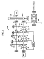
- FIG. 1 illustrates a schematic configuration of a vehicle equipped with a power transmission control device (hereinafter referred to as "this device") according to an embodiment of the present invention.
- This vehicle is a hybrid vehicle provided with an internal combustion engine and a motor/generator as power sources, and also provided with a so-called automated manual transmission (AMT) using a clutch and a multiple gear ratio transmission without a torque converter.
- AMT automated manual transmission
- This vehicle is provided with an engine E/G, a transmission T/M, a clutch C/D, and a motor/generator M/G.
- the E/G is one of well-known internal combustion engines, and is, for example, a gasoline engine using gasoline as a fuel or a diesel engine using light oil as a fuel.
- An output shaft A1 of the E/G is connected, via a flywheel F/W and a clutch disk C/D, to an input shaft A2 of the transmission T/M.
- the transmission T/M is one of well-known multiple gear ratio transmissions without a torque converter having a plurality of (for example, five) gear positions (shift positions) for forward travel, one gear position (shift position) for backward travel, and a neutral position.
- An output shaft A3 of the T/M is connected, via a differential gear DIF, to drive wheels of the vehicle.
- the T/M includes:
- the change/setting of the gear position in the T/M is carried out by a transmission actuator ACT2 (see FIG. 1 ) driving the sleeves S1, S2, and S3, thereby controlling axial positions of the sleeves S1, S2, and S3.
- the speed reduction ratio (ratio of the rotation speed Ni of the input shaft A2 to the rotation speed No of the output shaft A3) is adjusted by changing the gear position.
- the "speed reduction ratio" of an "N-th” speed is represented by "(number of teeth of GNo)/(number of teeth of GNi)" (N: 1, 2, 3, 4, and 5).
- the speed reduction ratio gradually decreases from "1st speed" to "5th speed".
- the clutch C/D is a friction clutch disk which includes one of well-known configurations and is provided so as to integrally rotate with the input shaft A2 of the transmission T/M. More specifically, to the flywheel F/W provided so as to integrally rotate with the output shaft A1 of the engine E/G, the clutch C/D (more precisely, clutch disk) is coaxially arranged so as to be opposed thereto. The axial position of the clutch C/D (more precisely, clutch disk) with respect to the flywheel F/W is adjustable. The axial position of the clutch C/D is adjusted by the clutch actuator ACT1 (see FIG. 1 ). Note that, the clutch C/D is not provided with a clutch pedal operated by a driver.
- clutch stroke CSt a travel amount in the axial direction from an original position (a position at which the clutch disk is furthest from the flywheel) toward the engaging direction (pressed direction) of the clutch C/D.
- the clutch stroke CSt is "0".
- the maximum torque (clutch torque Tc) which the clutch C/D can transfer, is adjusted.
- the motor/generator M/G has one of known structures (such as AC synchronous motor), and, for example, a rotor (not shown) is configured so as to integrally rotate with the output shaft of the M/G.
- a rotor not shown
- the output shaft of the M/G may be connected to the output shaft A3 of the T/M via a predetermined gear train.
- the driving torque of the output shaft of the M/G is transmitted, without intermediation of the T/M, to the output shaft A3 (namely, drive wheels) of the T/M.
- This device includes an accelerator opening sensor S1 for detecting an operated amount (accelerator opening) of the accelerator pedal AP, a shift position sensor S2 for detecting a position of a shift lever SF, and a brake sensor S3 for detecting absence/presence of an operation of a brake pedal BP.
- an accelerator opening sensor S1 for detecting an operated amount (accelerator opening) of the accelerator pedal AP
- a shift position sensor S2 for detecting a position of a shift lever SF
- a brake sensor S3 for detecting absence/presence of an operation of a brake pedal BP.
- this device includes an electronic control unit ECU.
- the ECU based on information from the sensors S1 to S3 and other sensors and the like, and other such information, controls the actuators ACT1 and ACT2, thereby controlling the clutch stroke CSt (and hence clutch torque Tc) of the C/D and the gear position of the T/M.
- the ECU controls a fuel injection amount of the E/G (opening of a throttle valve), thereby controlling the driving torque of the output shaft A1 of the E/G, and controls an inverter (not shown), thereby controlling the driving torque of the output shaft of the M/G.
- this vehicle is "the hybrid vehicle with the AMT", which is equipped with the AMT and is provided with the configuration in which the output shaft of the M/G is connected to the output shaft A3 of the T/M.
- the driving torque generated on the output shaft A1 by the combustion of the E/G is referred to as "EG torque Te”
- MG torque Tm the driving torque on the output shaft of the M/G
- Te and Tm take positive values in the acceleration direction of the vehicle, and take negative values in the deceleration direction.
- an EV travel mode, an EG travel mode, and an HV travel mode are selectively realized. Which of the EV travel mode, the EG travel mode, and the HV travel mode is realized is determined based on the travel state of the vehicle such as the vehicle speed and the accelerator opening.
- the MG torque Tm In the EG travel mode, the MG torque Tm is maintained to zero, the clutch C/D is adjusted to the engaged state (Tc>0), and the vehicle travels by using only the EG torque Te (>0).
- the clutch C/D In the HV travel mode, the clutch C/D is adjusted to the engaged state (Tc>0), and the vehicle travels by using both the EG torque Te (>0) and the MG torque Tm (>0).
- Tm is adjusted based on the travel state of the vehicle such as the accelerator opening.
- Te is adjusted based on the travel state of the vehicle such as the accelerator opening.
- the shift lever SL when the shift lever SL is in a position (such as a D range) corresponding to "an automatic mode", based on a gear change map (see FIG. 4 ) stored in the ROM in the ECU, and the travel state of the vehicle such as the vehicle speed and the accelerator opening, the shift position (gear position to be selected/realized) is selected. For example, when the current vehicle speed is ⁇ , and the current accelerator opening is ⁇ , "3rd speed" is selected as the shift position. On the other hand, when the shift lever SL is in a position (such as an M (manual) range) corresponding to a "manual mode", the shift position is selected based on the position of the shift lever SL.
- a gear position corresponding to a selected shift position is realized.
- the gear change action action when the gear position is changed
- the start of the gear change action corresponds to a start of a movement of the members (specifically, the sleeves) moving in relation to the change in the gear position
- the end of the gear change action corresponds to an end of the movement of the members.
- the shift position (namely, the gear position to be realized) is selected/changed based on the above-mentioned gear change map and the travel state of the vehicle (such as accelerator opening and the vehicle speed).
- the MG torque Tm is transmitted, without intermediation of the inside of the T/M, from the output shaft of the M/G to the output shaft A3 (namely, drive wheels) of the TIM.
- the necessity of sequentially changing "the gear position to be realized” based on the above-mentioned gear change map (see FIG. 4 ) is low.
- the action sound caused by "the gear change action” is unavoidably generated. Due to this action sound, occupants may feel a sense of discomfort.
- the noise level in the cabin when the noise level in the cabin is high, it is hard for the occupants to sense the action sound generated in the cabin, and when the noise level in the cabin is low, it is easy for the occupants to sense the action sound generated in the cabin. On this occasion, the noise level in the cabin increases as the vehicle speed increases.
- the gear position to be realized is changed in accordance with the above-mentioned gear change map and the travel state of the vehicle (vehicle speed and the accelerator opening).
- the gear position to be realized is maintained to the current gear position independently of the travel state of the vehicle. In other words, the change of the gear position is inhibited.
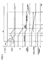
- FIG. 5 an example of the case where "the automatic mode" (D range) is selected/maintained by the SL, a travel mode other than the EV travel mode (specifically, the EG travel mode) is selected before a time t1, and, the EV travel mode is selected after the time t1 is shown.
- a broken line represents a case where the above-mentioned "change in gear position” is not inhibited
- a solid line represents a case where "the change in gear position” is inhibited by this device.
- the clutch torque Tc is maintained to zero (namely, the clutch C/D is maintained in the disengaged state). In other words, after the time t2, the vehicle travels by using only the MG torque.
- the accelerator opening is maintained constant until a time t3, and, after the time t3, decreases toward zero.
- the MG torque Tm decreases, and, after a time immediately before the time T4, Tm transitions through negative values (so-called regeneration state).
- the vehicle speed is also maintained constant until the time t3, and, after the time t3, decreases toward zero.
- the gear position to be realized is, in accordance with the gear change map (see FIG. 4 ), maintained to a "4th speed” until the time t3. From the time t3 to the time t4, in response to the decreases in the vehicle speed and the accelerator opening, in accordance with the gear change map (see FIG. 4 ), the gear change action (change in gear position) from the "4th speed” to the "3rd speed” is carried out. This is, in this stage, based on the condition that the vehicle speed is higher than the predetermined speed Vth. In other words, in this stage, the noise level in the cabin is high, and thus, the action sound caused by the gear change action is hardly sensed by the occupants. Thus, while the action sound caused by the gear change action is not sensed by the occupants, "the gear position to be realized" is properly changed depending on the travel state of the vehicle.
- the gear position to be realized is properly changed depending on the travel state of the vehicle.
- the vehicle speed is equal to or lower than the predetermined speed Vth (namely, the noise level in the cabin is low)
- the gear position is not changed, and the action sound caused by the change in the gear position is not generated.
- the gear position to be realized is changed to the "1st speed” (gear position having the largest speed reduction ratio).
- the present invention is not limited to the above-mentioned embodiment, and various modifications can be employed within the scope of the present invention.
- the three types of travel modes that is, the EV travel mode, the EG travel mode, and the HV travel mode
- the three types of travel modes are selectively realized.
- two types of travel modes that is, the EV travel mode and the EG travel mode
- may be selectively realized namely, that the HV travel mode cannot be realized).
Landscapes
- Engineering & Computer Science (AREA)
- Transportation (AREA)
- Mechanical Engineering (AREA)
- Chemical & Material Sciences (AREA)
- Combustion & Propulsion (AREA)
- Automation & Control Theory (AREA)
- Hybrid Electric Vehicles (AREA)
- Electric Propulsion And Braking For Vehicles (AREA)
- Control Of Transmission Device (AREA)
Applications Claiming Priority (1)
| Application Number | Priority Date | Filing Date | Title |
|---|---|---|---|
| JP2011204076A JP5918953B2 (ja) | 2011-09-20 | 2011-09-20 | 車両の動力伝達制御装置 |
Publications (3)
| Publication Number | Publication Date |
|---|---|
| EP2572916A2 true EP2572916A2 (fr) | 2013-03-27 |
| EP2572916A3 EP2572916A3 (fr) | 2015-07-15 |
| EP2572916B1 EP2572916B1 (fr) | 2017-05-10 |
Family
ID=46888941
Family Applications (1)
| Application Number | Title | Priority Date | Filing Date |
|---|---|---|---|
| EP12184944.2A Not-in-force EP2572916B1 (fr) | 2011-09-20 | 2012-09-19 | Dispositif de commande de transmission de puissance pour véhicule |
Country Status (4)
| Country | Link |
|---|---|
| US (1) | US8725336B2 (fr) |
| EP (1) | EP2572916B1 (fr) |
| JP (1) | JP5918953B2 (fr) |
| CN (1) | CN103010205B (fr) |
Families Citing this family (9)
| Publication number | Priority date | Publication date | Assignee | Title |
|---|---|---|---|---|
| DE102014213080A1 (de) * | 2013-09-20 | 2015-04-16 | Robert Bosch Gmbh | Verfahren zum Abstellen einer Brennkraftmaschine |
| JP2015074294A (ja) * | 2013-10-07 | 2015-04-20 | 日野自動車株式会社 | 車両および制御方法 |
| US9315190B2 (en) | 2014-04-30 | 2016-04-19 | Ford Global Technologies, Llc | Hybrid electric vehicle preferred mode |
| JP6197956B2 (ja) * | 2014-07-25 | 2017-09-20 | 日産自動車株式会社 | 車両の制御装置、及びその制御方法 |
| JP6373164B2 (ja) * | 2014-10-28 | 2018-08-15 | アイシン・エーアイ株式会社 | 車両の動力伝達制御装置 |
| US11062344B2 (en) | 2015-05-13 | 2021-07-13 | Abl Ip Holding, Llc | Systems and methods for POP display and wireless beacon execution with wireless network gateways |
| CN109863600B (zh) | 2016-11-02 | 2023-06-20 | 索尼半导体解决方案公司 | 成像器件、成像装置以及电子设备 |
| JP6748060B2 (ja) * | 2017-12-28 | 2020-08-26 | 本田技研工業株式会社 | 車両の制御装置 |
| JP7513881B2 (ja) | 2020-09-24 | 2024-07-10 | スズキ株式会社 | 自動変速制御装置 |
Citations (2)
| Publication number | Priority date | Publication date | Assignee | Title |
|---|---|---|---|---|
| JP2000224710A (ja) | 1999-01-27 | 2000-08-11 | Mitsubishi Motors Corp | ハイブリッド車 |
| JP2006097740A (ja) | 2004-09-28 | 2006-04-13 | Aisin Seiki Co Ltd | 自動変速機の変速制御装置 |
Family Cites Families (18)
| Publication number | Priority date | Publication date | Assignee | Title |
|---|---|---|---|---|
| JPH06255389A (ja) * | 1991-02-26 | 1994-09-13 | Mitsubishi Electric Corp | 車両の走行制御装置 |
| JP3550067B2 (ja) * | 2000-01-17 | 2004-08-04 | 本田技研工業株式会社 | ハイブリッド車両の制御装置 |
| JP4108265B2 (ja) * | 2000-11-22 | 2008-06-25 | 本田技研工業株式会社 | 車両用クラッチの接続状態判定装置およびこれを用いた変速制御装置 |
| JP3491620B2 (ja) * | 2000-12-15 | 2004-01-26 | 日産自動車株式会社 | 四輪駆動車両 |
| JP3499852B2 (ja) * | 2001-12-03 | 2004-02-23 | 本田技研工業株式会社 | 動力伝達機構 |
| JP4265564B2 (ja) * | 2004-11-09 | 2009-05-20 | トヨタ自動車株式会社 | 車両およびその制御方法 |
| JP2006214454A (ja) * | 2005-02-01 | 2006-08-17 | Hitachi Ltd | 自動車の変速機制御装置及び自動変速装置 |
| JP2007022148A (ja) * | 2005-07-12 | 2007-02-01 | Honda Motor Co Ltd | ハイブリッド車両における変速制御装置 |
| DE102006049995A1 (de) * | 2006-10-24 | 2008-05-08 | Zf Friedrichshafen Ag | Verfahren zum Steuern und/oder Regeln eines Automatgetriebes |
| JP5055990B2 (ja) * | 2006-12-08 | 2012-10-24 | トヨタ自動車株式会社 | 車両用駆動装置の制御装置 |
| US8204659B2 (en) * | 2007-03-12 | 2012-06-19 | Nissan Motor Co., Ltd. | Engine start control system for hybrid vehicle |
| JP4412346B2 (ja) * | 2007-04-20 | 2010-02-10 | トヨタ自動車株式会社 | ハイブリッド車両の駆動制御装置 |
| JP2010083351A (ja) * | 2008-09-30 | 2010-04-15 | Mazda Motor Corp | 車両用駆動装置の制御方法 |
| US8374760B2 (en) * | 2008-12-31 | 2013-02-12 | Mark Snyder | Control of multi-speed transmission |
| JP5340790B2 (ja) * | 2009-04-08 | 2013-11-13 | アイシン・エーアイ株式会社 | 車両の動力伝達制御装置 |
| JP2010247689A (ja) * | 2009-04-16 | 2010-11-04 | Aisin Ai Co Ltd | 車両の動力伝達制御装置 |
| JP5462057B2 (ja) * | 2010-04-08 | 2014-04-02 | アイシン・エーアイ株式会社 | 車両の動力伝達制御装置 |
| JP2012020619A (ja) * | 2010-07-13 | 2012-02-02 | Aisin Ai Co Ltd | 車両の動力伝達制御装置 |
-
2011
- 2011-09-20 JP JP2011204076A patent/JP5918953B2/ja active Active
-
2012
- 2012-08-17 CN CN201210294991.XA patent/CN103010205B/zh not_active Expired - Fee Related
- 2012-09-19 EP EP12184944.2A patent/EP2572916B1/fr not_active Not-in-force
- 2012-09-20 US US13/623,293 patent/US8725336B2/en not_active Expired - Fee Related
Patent Citations (2)
| Publication number | Priority date | Publication date | Assignee | Title |
|---|---|---|---|---|
| JP2000224710A (ja) | 1999-01-27 | 2000-08-11 | Mitsubishi Motors Corp | ハイブリッド車 |
| JP2006097740A (ja) | 2004-09-28 | 2006-04-13 | Aisin Seiki Co Ltd | 自動変速機の変速制御装置 |
Also Published As
| Publication number | Publication date |
|---|---|
| CN103010205A (zh) | 2013-04-03 |
| US20130073131A1 (en) | 2013-03-21 |
| JP2013063715A (ja) | 2013-04-11 |
| EP2572916B1 (fr) | 2017-05-10 |
| CN103010205B (zh) | 2016-02-24 |
| US8725336B2 (en) | 2014-05-13 |
| JP5918953B2 (ja) | 2016-05-18 |
| EP2572916A3 (fr) | 2015-07-15 |
Similar Documents
| Publication | Publication Date | Title |
|---|---|---|
| EP2572916B1 (fr) | Dispositif de commande de transmission de puissance pour véhicule | |
| US8540603B2 (en) | Vehicle power transmission control device | |
| US8712622B2 (en) | Power transmission control device for vehicle | |
| US20180186230A1 (en) | Device for controlling driving force of hybrid vehicle | |
| WO2013008858A1 (fr) | Appareil de commande de la transmission de l'énergie motrice pour véhicule | |
| WO2013145896A1 (fr) | Dispositif de commande de la propulsion d'un véhicule hybride | |
| US8210985B2 (en) | Vehicular power transmission control apparatus | |
| EP3222454A1 (fr) | Dispositif de transmission pour véhicule hybride | |
| EP2574829A1 (fr) | Système d'instruction de changement de vitesse pour véhicules | |
| US20140083247A1 (en) | Manual transmission | |
| JP2017114337A (ja) | 車両用駆動装置の制御装置 | |
| EP2653364A1 (fr) | Dispositif de commande de transmission de puissance pour véhicule | |
| EP2548780A2 (fr) | Dispositif de commande de transmission de puissance pour véhicule | |
| US10279795B2 (en) | Control device | |
| US8758194B2 (en) | Power transmission control device for vehicle | |
| JP5715848B2 (ja) | 車両の動力伝達制御装置 | |
| JP5462057B2 (ja) | 車両の動力伝達制御装置 | |
| JP5990023B2 (ja) | 車両の動力伝達制御装置 | |
| JP2016011075A (ja) | 車両の動力伝達制御装置 | |
| JP6109581B2 (ja) | 車両の動力伝達制御装置 | |
| CN110312627B (zh) | 用于控制混合动力机动车辆半自动变速箱的方法和装置 | |
| JP6491051B2 (ja) | 車両の動力伝達制御装置 | |
| JP6017324B2 (ja) | 車両の動力伝達制御装置 | |
| WO2012077382A1 (fr) | Dispositif de commande de transmission de puissance de véhicule | |
| JP2012126317A (ja) | 車両の動力伝達制御装置 |
Legal Events
| Date | Code | Title | Description |
|---|---|---|---|
| PUAI | Public reference made under article 153(3) epc to a published international application that has entered the european phase |
Free format text: ORIGINAL CODE: 0009012 |
|
| AK | Designated contracting states |
Kind code of ref document: A2 Designated state(s): AL AT BE BG CH CY CZ DE DK EE ES FI FR GB GR HR HU IE IS IT LI LT LU LV MC MK MT NL NO PL PT RO RS SE SI SK SM TR |
|
| AX | Request for extension of the european patent |
Extension state: BA ME |
|
| PUAL | Search report despatched |
Free format text: ORIGINAL CODE: 0009013 |
|
| AK | Designated contracting states |
Kind code of ref document: A3 Designated state(s): AL AT BE BG CH CY CZ DE DK EE ES FI FR GB GR HR HU IE IS IT LI LT LU LV MC MK MT NL NO PL PT RO RS SE SI SK SM TR |
|
| AX | Request for extension of the european patent |
Extension state: BA ME |
|
| RIC1 | Information provided on ipc code assigned before grant |
Ipc: B60W 10/02 20060101ALI20150605BHEP Ipc: B60W 10/11 20120101ALI20150605BHEP Ipc: B60W 30/18 20120101ALI20150605BHEP Ipc: B60K 6/48 20071001AFI20150605BHEP |
|
| 17P | Request for examination filed |
Effective date: 20151126 |
|
| RBV | Designated contracting states (corrected) |
Designated state(s): AL AT BE BG CH CY CZ DE DK EE ES FI FR GB GR HR HU IE IS IT LI LT LU LV MC MK MT NL NO PL PT RO RS SE SI SK SM TR |
|
| REG | Reference to a national code |
Ref country code: DE Ref legal event code: R079 Ref document number: 602012032182 Country of ref document: DE Free format text: PREVIOUS MAIN CLASS: B60K0006480000 Ipc: B60W0020300000 |
|
| GRAP | Despatch of communication of intention to grant a patent |
Free format text: ORIGINAL CODE: EPIDOSNIGR1 |
|
| RIC1 | Information provided on ipc code assigned before grant |
Ipc: B60W 10/11 20120101ALI20161206BHEP Ipc: B60K 6/48 20071001ALI20161206BHEP Ipc: B60W 20/30 20160101AFI20161206BHEP Ipc: B60W 10/02 20060101ALI20161206BHEP Ipc: B60W 30/18 20120101ALI20161206BHEP |
|
| INTG | Intention to grant announced |
Effective date: 20170104 |
|
| GRAS | Grant fee paid |
Free format text: ORIGINAL CODE: EPIDOSNIGR3 |
|
| GRAA | (expected) grant |
Free format text: ORIGINAL CODE: 0009210 |
|
| AK | Designated contracting states |
Kind code of ref document: B1 Designated state(s): AL AT BE BG CH CY CZ DE DK EE ES FI FR GB GR HR HU IE IS IT LI LT LU LV MC MK MT NL NO PL PT RO RS SE SI SK SM TR |
|
| REG | Reference to a national code |
Ref country code: GB Ref legal event code: FG4D |
|
| REG | Reference to a national code |
Ref country code: AT Ref legal event code: REF Ref document number: 891982 Country of ref document: AT Kind code of ref document: T Effective date: 20170515 Ref country code: CH Ref legal event code: EP |
|
| REG | Reference to a national code |
Ref country code: IE Ref legal event code: FG4D |
|
| REG | Reference to a national code |
Ref country code: DE Ref legal event code: R096 Ref document number: 602012032182 Country of ref document: DE |
|
| REG | Reference to a national code |
Ref country code: FR Ref legal event code: PLFP Year of fee payment: 6 |
|
| REG | Reference to a national code |
Ref country code: NL Ref legal event code: MP Effective date: 20170510 |
|
| REG | Reference to a national code |
Ref country code: LT Ref legal event code: MG4D |
|
| REG | Reference to a national code |
Ref country code: AT Ref legal event code: MK05 Ref document number: 891982 Country of ref document: AT Kind code of ref document: T Effective date: 20170510 |
|
| PG25 | Lapsed in a contracting state [announced via postgrant information from national office to epo] |
Ref country code: NO Free format text: LAPSE BECAUSE OF FAILURE TO SUBMIT A TRANSLATION OF THE DESCRIPTION OR TO PAY THE FEE WITHIN THE PRESCRIBED TIME-LIMIT Effective date: 20170810 Ref country code: GR Free format text: LAPSE BECAUSE OF FAILURE TO SUBMIT A TRANSLATION OF THE DESCRIPTION OR TO PAY THE FEE WITHIN THE PRESCRIBED TIME-LIMIT Effective date: 20170811 Ref country code: AT Free format text: LAPSE BECAUSE OF FAILURE TO SUBMIT A TRANSLATION OF THE DESCRIPTION OR TO PAY THE FEE WITHIN THE PRESCRIBED TIME-LIMIT Effective date: 20170510 Ref country code: LT Free format text: LAPSE BECAUSE OF FAILURE TO SUBMIT A TRANSLATION OF THE DESCRIPTION OR TO PAY THE FEE WITHIN THE PRESCRIBED TIME-LIMIT Effective date: 20170510 Ref country code: FI Free format text: LAPSE BECAUSE OF FAILURE TO SUBMIT A TRANSLATION OF THE DESCRIPTION OR TO PAY THE FEE WITHIN THE PRESCRIBED TIME-LIMIT Effective date: 20170510 Ref country code: HR Free format text: LAPSE BECAUSE OF FAILURE TO SUBMIT A TRANSLATION OF THE DESCRIPTION OR TO PAY THE FEE WITHIN THE PRESCRIBED TIME-LIMIT Effective date: 20170510 Ref country code: ES Free format text: LAPSE BECAUSE OF FAILURE TO SUBMIT A TRANSLATION OF THE DESCRIPTION OR TO PAY THE FEE WITHIN THE PRESCRIBED TIME-LIMIT Effective date: 20170510 |
|
| PG25 | Lapsed in a contracting state [announced via postgrant information from national office to epo] |
Ref country code: RS Free format text: LAPSE BECAUSE OF FAILURE TO SUBMIT A TRANSLATION OF THE DESCRIPTION OR TO PAY THE FEE WITHIN THE PRESCRIBED TIME-LIMIT Effective date: 20170510 Ref country code: PL Free format text: LAPSE BECAUSE OF FAILURE TO SUBMIT A TRANSLATION OF THE DESCRIPTION OR TO PAY THE FEE WITHIN THE PRESCRIBED TIME-LIMIT Effective date: 20170510 Ref country code: NL Free format text: LAPSE BECAUSE OF FAILURE TO SUBMIT A TRANSLATION OF THE DESCRIPTION OR TO PAY THE FEE WITHIN THE PRESCRIBED TIME-LIMIT Effective date: 20170510 Ref country code: IS Free format text: LAPSE BECAUSE OF FAILURE TO SUBMIT A TRANSLATION OF THE DESCRIPTION OR TO PAY THE FEE WITHIN THE PRESCRIBED TIME-LIMIT Effective date: 20170910 Ref country code: LV Free format text: LAPSE BECAUSE OF FAILURE TO SUBMIT A TRANSLATION OF THE DESCRIPTION OR TO PAY THE FEE WITHIN THE PRESCRIBED TIME-LIMIT Effective date: 20170510 Ref country code: BG Free format text: LAPSE BECAUSE OF FAILURE TO SUBMIT A TRANSLATION OF THE DESCRIPTION OR TO PAY THE FEE WITHIN THE PRESCRIBED TIME-LIMIT Effective date: 20170810 Ref country code: SE Free format text: LAPSE BECAUSE OF FAILURE TO SUBMIT A TRANSLATION OF THE DESCRIPTION OR TO PAY THE FEE WITHIN THE PRESCRIBED TIME-LIMIT Effective date: 20170510 |
|
| PG25 | Lapsed in a contracting state [announced via postgrant information from national office to epo] |
Ref country code: SK Free format text: LAPSE BECAUSE OF FAILURE TO SUBMIT A TRANSLATION OF THE DESCRIPTION OR TO PAY THE FEE WITHIN THE PRESCRIBED TIME-LIMIT Effective date: 20170510 Ref country code: CZ Free format text: LAPSE BECAUSE OF FAILURE TO SUBMIT A TRANSLATION OF THE DESCRIPTION OR TO PAY THE FEE WITHIN THE PRESCRIBED TIME-LIMIT Effective date: 20170510 Ref country code: DK Free format text: LAPSE BECAUSE OF FAILURE TO SUBMIT A TRANSLATION OF THE DESCRIPTION OR TO PAY THE FEE WITHIN THE PRESCRIBED TIME-LIMIT Effective date: 20170510 Ref country code: RO Free format text: LAPSE BECAUSE OF FAILURE TO SUBMIT A TRANSLATION OF THE DESCRIPTION OR TO PAY THE FEE WITHIN THE PRESCRIBED TIME-LIMIT Effective date: 20170510 Ref country code: EE Free format text: LAPSE BECAUSE OF FAILURE TO SUBMIT A TRANSLATION OF THE DESCRIPTION OR TO PAY THE FEE WITHIN THE PRESCRIBED TIME-LIMIT Effective date: 20170510 |
|
| REG | Reference to a national code |
Ref country code: DE Ref legal event code: R097 Ref document number: 602012032182 Country of ref document: DE |
|
| PG25 | Lapsed in a contracting state [announced via postgrant information from national office to epo] |
Ref country code: SM Free format text: LAPSE BECAUSE OF FAILURE TO SUBMIT A TRANSLATION OF THE DESCRIPTION OR TO PAY THE FEE WITHIN THE PRESCRIBED TIME-LIMIT Effective date: 20170510 |
|
| PLBE | No opposition filed within time limit |
Free format text: ORIGINAL CODE: 0009261 |
|
| STAA | Information on the status of an ep patent application or granted ep patent |
Free format text: STATUS: NO OPPOSITION FILED WITHIN TIME LIMIT |
|
| 26N | No opposition filed |
Effective date: 20180213 |
|
| REG | Reference to a national code |
Ref country code: CH Ref legal event code: PL |
|
| PG25 | Lapsed in a contracting state [announced via postgrant information from national office to epo] |
Ref country code: SI Free format text: LAPSE BECAUSE OF FAILURE TO SUBMIT A TRANSLATION OF THE DESCRIPTION OR TO PAY THE FEE WITHIN THE PRESCRIBED TIME-LIMIT Effective date: 20170510 Ref country code: MC Free format text: LAPSE BECAUSE OF FAILURE TO SUBMIT A TRANSLATION OF THE DESCRIPTION OR TO PAY THE FEE WITHIN THE PRESCRIBED TIME-LIMIT Effective date: 20170510 |
|
| REG | Reference to a national code |
Ref country code: IE Ref legal event code: MM4A |
|
| REG | Reference to a national code |
Ref country code: BE Ref legal event code: MM Effective date: 20170930 |
|
| PG25 | Lapsed in a contracting state [announced via postgrant information from national office to epo] |
Ref country code: LU Free format text: LAPSE BECAUSE OF NON-PAYMENT OF DUE FEES Effective date: 20170919 |
|
| PG25 | Lapsed in a contracting state [announced via postgrant information from national office to epo] |
Ref country code: LI Free format text: LAPSE BECAUSE OF NON-PAYMENT OF DUE FEES Effective date: 20170930 Ref country code: CH Free format text: LAPSE BECAUSE OF NON-PAYMENT OF DUE FEES Effective date: 20170930 Ref country code: IE Free format text: LAPSE BECAUSE OF NON-PAYMENT OF DUE FEES Effective date: 20170919 |
|
| REG | Reference to a national code |
Ref country code: FR Ref legal event code: PLFP Year of fee payment: 7 |
|
| PG25 | Lapsed in a contracting state [announced via postgrant information from national office to epo] |
Ref country code: BE Free format text: LAPSE BECAUSE OF NON-PAYMENT OF DUE FEES Effective date: 20170930 |
|
| PG25 | Lapsed in a contracting state [announced via postgrant information from national office to epo] |
Ref country code: MT Free format text: LAPSE BECAUSE OF NON-PAYMENT OF DUE FEES Effective date: 20170919 |
|
| RIC2 | Information provided on ipc code assigned after grant |
Ipc: B60W 20/30 20160101AFI20161206BHEP Ipc: B60K 6/48 20071001ALI20161206BHEP Ipc: B60W 10/11 20120101ALI20161206BHEP Ipc: B60W 30/18 20120101ALI20161206BHEP Ipc: B60W 10/02 20060101ALI20161206BHEP |
|
| PG25 | Lapsed in a contracting state [announced via postgrant information from national office to epo] |
Ref country code: HU Free format text: LAPSE BECAUSE OF FAILURE TO SUBMIT A TRANSLATION OF THE DESCRIPTION OR TO PAY THE FEE WITHIN THE PRESCRIBED TIME-LIMIT; INVALID AB INITIO Effective date: 20120919 |
|
| PG25 | Lapsed in a contracting state [announced via postgrant information from national office to epo] |
Ref country code: CY Free format text: LAPSE BECAUSE OF NON-PAYMENT OF DUE FEES Effective date: 20170510 |
|
| PGFP | Annual fee paid to national office [announced via postgrant information from national office to epo] |
Ref country code: IT Payment date: 20190917 Year of fee payment: 8 Ref country code: FR Payment date: 20190815 Year of fee payment: 8 Ref country code: DE Payment date: 20190903 Year of fee payment: 8 |
|
| PG25 | Lapsed in a contracting state [announced via postgrant information from national office to epo] |
Ref country code: MK Free format text: LAPSE BECAUSE OF FAILURE TO SUBMIT A TRANSLATION OF THE DESCRIPTION OR TO PAY THE FEE WITHIN THE PRESCRIBED TIME-LIMIT Effective date: 20170510 |
|
| PGFP | Annual fee paid to national office [announced via postgrant information from national office to epo] |
Ref country code: GB Payment date: 20190920 Year of fee payment: 8 |
|
| PG25 | Lapsed in a contracting state [announced via postgrant information from national office to epo] |
Ref country code: TR Free format text: LAPSE BECAUSE OF FAILURE TO SUBMIT A TRANSLATION OF THE DESCRIPTION OR TO PAY THE FEE WITHIN THE PRESCRIBED TIME-LIMIT Effective date: 20170510 |
|
| PG25 | Lapsed in a contracting state [announced via postgrant information from national office to epo] |
Ref country code: PT Free format text: LAPSE BECAUSE OF FAILURE TO SUBMIT A TRANSLATION OF THE DESCRIPTION OR TO PAY THE FEE WITHIN THE PRESCRIBED TIME-LIMIT Effective date: 20170510 |
|
| PG25 | Lapsed in a contracting state [announced via postgrant information from national office to epo] |
Ref country code: AL Free format text: LAPSE BECAUSE OF FAILURE TO SUBMIT A TRANSLATION OF THE DESCRIPTION OR TO PAY THE FEE WITHIN THE PRESCRIBED TIME-LIMIT Effective date: 20170510 |
|
| REG | Reference to a national code |
Ref country code: DE Ref legal event code: R119 Ref document number: 602012032182 Country of ref document: DE |
|
| GBPC | Gb: european patent ceased through non-payment of renewal fee |
Effective date: 20200919 |
|
| PG25 | Lapsed in a contracting state [announced via postgrant information from national office to epo] |
Ref country code: DE Free format text: LAPSE BECAUSE OF NON-PAYMENT OF DUE FEES Effective date: 20210401 Ref country code: FR Free format text: LAPSE BECAUSE OF NON-PAYMENT OF DUE FEES Effective date: 20200930 |
|
| PG25 | Lapsed in a contracting state [announced via postgrant information from national office to epo] |
Ref country code: GB Free format text: LAPSE BECAUSE OF NON-PAYMENT OF DUE FEES Effective date: 20200919 |
|
| PG25 | Lapsed in a contracting state [announced via postgrant information from national office to epo] |
Ref country code: IT Free format text: LAPSE BECAUSE OF NON-PAYMENT OF DUE FEES Effective date: 20200919 |