EP2555429A1 - Semiconductor circuit - Google Patents
Semiconductor circuit Download PDFInfo
- Publication number
- EP2555429A1 EP2555429A1 EP12275101A EP12275101A EP2555429A1 EP 2555429 A1 EP2555429 A1 EP 2555429A1 EP 12275101 A EP12275101 A EP 12275101A EP 12275101 A EP12275101 A EP 12275101A EP 2555429 A1 EP2555429 A1 EP 2555429A1
- Authority
- EP
- European Patent Office
- Prior art keywords
- signal
- semiconductor circuit
- voltage
- inverter
- circuit according
- Prior art date
- Legal status (The legal status is an assumption and is not a legal conclusion. Google has not performed a legal analysis and makes no representation as to the accuracy of the status listed.)
- Withdrawn
Links
Images


Classifications
-
- H—ELECTRICITY
- H03—ELECTRONIC CIRCUITRY
- H03K—PULSE TECHNIQUE
- H03K5/00—Manipulating of pulses not covered by one of the other main groups of this subclass
- H03K5/13—Arrangements having a single output and transforming input signals into pulses delivered at desired time intervals
- H03K5/133—Arrangements having a single output and transforming input signals into pulses delivered at desired time intervals using a chain of active delay devices
-
- H—ELECTRICITY
- H03—ELECTRONIC CIRCUITRY
- H03K—PULSE TECHNIQUE
- H03K5/00—Manipulating of pulses not covered by one of the other main groups of this subclass
- H03K5/125—Discriminating pulses
- H03K5/1252—Suppression or limitation of noise or interference
- H03K5/1254—Suppression or limitation of noise or interference specially adapted for pulses generated by closure of switches, i.e. anti-bouncing devices
-
- H—ELECTRICITY
- H03—ELECTRONIC CIRCUITRY
- H03K—PULSE TECHNIQUE
- H03K5/00—Manipulating of pulses not covered by one of the other main groups of this subclass
- H03K5/125—Discriminating pulses
- H03K5/1252—Suppression or limitation of noise or interference
-
- H—ELECTRICITY
- H03—ELECTRONIC CIRCUITRY
- H03K—PULSE TECHNIQUE
- H03K5/00—Manipulating of pulses not covered by one of the other main groups of this subclass
- H03K5/13—Arrangements having a single output and transforming input signals into pulses delivered at desired time intervals
Definitions
- the present invention relates to a semiconductor circuit mounted in electronic devices, and more particularly, to a semiconductor circuit capable of removing noise mixed in an input signal.
- noise occurs in a power line or a signal line, and there is a problem of malfunction of a semiconductor circuit mounted in the electronic device due to influence of noise.
- noise when noise is mixed in a signal input to the semiconductor circuit, it may be a main cause of interfering with a normal operation of the electronic device and the malfunction of the electronic device since the noise may be determined as the input signal.
- the present invention has been invented in order to overcome the above-described problems and it is, therefore, an object of the present invention to provide a semiconductor circuit capable of more effectively removing low level noise mixed in a high level input signal and high level noise mixed in a low level input signal.
- a semiconductor circuit including: a delay unit for delaying an input signal by a predetermined time to output the delayed signal; a voltage adjusting unit for charging and discharge voltage according to a level of the input signal; and a combination unit for controlling the charging and discharging operations of the voltage adjusting unit according to signals generated using the level of the input signal and a level of the signal output from the delay unit.
- the delay unit may include a plurality of inverters which invert the level of the input signal to output the inverted signal.
- the delay unit may include first and second inverters connected in series, and the voltage adjusting unit may be connected between a connection point of the first and second inverters and a ground.
- the first inverter may include first and second switches which selectively perform a switching operation according to the level of the input signal.
- the first and second switches may consist of PMOS and NMOS, respectively.
- the first inverter may include first and second current sources which are connected to the first and second switches, respectively.
- the voltage adjusting unit may consist of a condenser which charges and discharges the voltage according to the switching operation of the first and second switches.
- the first inverter may open the first switch and close the second switch when the input signal varies from low level to high level, and the voltage adjusting unit may discharge the voltage according to the closing operation of the second switch.
- the second inverter may output a high level signal when the voltage discharged from the voltage adjusting unit is lower than a preset reference voltage and output a low level signal when the voltage discharged from the voltage adjusting unit is not lower than the preset reference voltage.
- the first inverter may close the first switch and open the second switch when the input signal varies from high level to low level, and the voltage adjusting unit may charge the voltage according to the closing operation of the first switch.
- the second inverter may output a low level signal when the voltage charged in the voltage adjusting unit is higher than the preset reference voltage and output a high level signal when the voltage charged in the voltage adjusting unit is not higher than the preset reference voltage.
- the combination unit may include first and second operators which perform a logic operation by combining the input signal and the signal output from the delay unit; and third and fourth switches which perform a switching operation according to levels of signals generated by the first and second operators.
- the first and second operators may consist of an OR gate and an AND gate, respectively.
- the delay unit may include first to sixth inverters sequentially connected in series, and the voltage adjusting unit may be connected between a connection point of the third and fourth inverters and the ground.
- the third inverter may include first and second switches which selectively perform a switching operation according to the level of the input signal; and first and second current sources which are connected to the first and second switches, respectively.
- the combination unit may control the charging and discharging operations of the voltage adjusting unit according to signals generated by combining a signal input to the second inverter and a signal output from the fifth inverter.
- the combination unit may include first and second operators which perform a logic operation by combining the signal input to the second inverter and the signal output from the fifth inverter; and third and fourth switches which perform a switching operation according to levels of signals generated by the first and second operators.
- the first and second operators may consist of a NAND gate and a NOR gate, respectively.
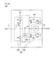
- FIG. 1 is a configuration diagram of a semiconductor circuit in accordance with an embodiment of the present invention
- FIG. 2 is a timing diagram showing an operation of the semiconductor circuit for removing noise
- FIG. 3a is a configuration diagram of the semiconductor circuit in which first and second resistors are connected instead of first and second current sources of FIG. 1 .
- FIG. 3b is a configuration diagram of the semiconductor circuit from which a first switch of FIG. 1 is removed;
- FIG. 3c is a configuration diagram of the semiconductor circuit from which a second switch of FIG. 1 is removed;
- FIG. 4 is a configuration diagram of a semiconductor circuit in accordance with another embodiment of the present invention.
- FIG. 5 is a configuration diagram of a semiconductor circuit in accordance with still another embodiment of the present invention.
- FIG. 1 is a configuration diagram of a semiconductor circuit in accordance with an embodiment of the present invention
- FIG. 2 is a timing diagram showing an operation of the semiconductor circuit for removing noise.
- a semiconductor circuit 100 includes a delay unit 120, a voltage adjusting unit 140, and a combination unit 160.
- the delay unit 120 which is a means of delaying a signal P1 input to an input terminal IN of the semiconductor circuit 100 by a predetermined time to output the delayed signal, may consist of a plurality of (in detail, even number) inverters which invert a level of the input signal to output the inverted signal.
- the delay unit 120 shown in FIG 1 may consist of first and second inverters 122 and 124 connected in series, and the first inverter 122 may include first and second switches Q1 and Q2 which selectively perform a switching operation according to the level of the input signal P1 and first and second current sources S1 and S2 which are respectively connected to the first and second switches Q1 and Q2 to supply current to the first and second switches Q1 and Q2.
- first inverter 122 is a CMOS inverter, it is preferred that the first and second switches Q1 and Q2 consist of PMOS and NMOS, respectively.
- the first inverter 122 When the input signal P1 varies from low level to high level, the first switch Q1, PMOS, is opened (OFF) and on the contrary, the second switch Q2, NMOS, is closed (ON) so that current flows to a ground through the second switch Q2 and the second current source S2.
- the first switch Q1, PMOS is closed (ON) and on the contrary, the second switch Q2, NMOS, is opened (OFF) so that current output from the first current source S1 flows to the first switch Q1.
- the voltage adjusting unit 140 which is a means of charging or discharging voltage according to the level of the input signal P1, may consist of a condenser C1 positioned between a connection point A of the first and second inverters 122 and 124 and the ground.
- the voltage adjusting unit 140 charges or discharges voltage according to the switching operations of the first and second switches Q1 and Q2 of the first inverter 122. For example, as in FIG. 2 , when the signal P1 input to the input terminal IN varies from low level to high level, the first switch Q1, PMOS, is opened (OFF) and on the contrary, the second switch Q2, NMOS, is closed (ON) so that the voltage charged in the condenser C1 is discharged through the second switch Q2 and the second current source S2.
- the voltage charged in the condenser C1 is reduced with a predetermined slope, and the second inverter 124 outputs a high level signal P3 when the discharged voltage (voltage of a signal P2) is lower than a reference voltage of the second inverter 124.
- the second inverter 124 outputs the low level signal P3 by determining that high level noise is mixed in the low level input signal P1 when the discharged voltage (voltage of the signal P2) is not lower than the reference voltage of the second inverter 124.
- a time until the input signal P1 varies from low level to high level and the output signal P3 is output becomes a noise filtering time t0 of removing the high level noise mixed in the low level input signal P1 as shown in FIG. 2 , and a high level signal t1 with a pulse width shorter than the noise filtering time t0 is recognized as noise and removed.
- the first switch Q1, PMOS is closed (ON) and on the contrary, the second switch Q2, NMOS, is opened (OFF) so that the condenser C1 is charged through the first current source S1 and the first switch Q1.
- the voltage charged in the condenser C1 is increased with a predetermined slope, and the second inverter 124 outputs the low level signal P3 when the charged voltage (voltage of the signal P2) is higher than the reference voltage of the second inverter 124.
- the second inverter 124 outputs the high level signal P3 as it is by determining that low level noise is mixed in the high level input signal when the charged voltage (voltage of the signal P2) is not higher than the reference voltage of the second inverter 124.
- the combination unit 160 which is a means of controlling charging and discharging operations of the voltage adjusting unit 140 according to signals generated using the level of the signal P1 input to the input terminal P1 and the level of the signal P3 output from an output terminal OUT, controls the charging and discharging operations of the voltage adjusting unit 140 according to signals P4 and P5 generated by combining the signal P1 input to the input terminal IN and the signal P3 output from the output terminal OUT and may consist of first and second operators G1 and G2 and third and fourth switches Q3 and Q4.
- the first and second operators G1 and G2 may consist of an OR gate and an AND gate, which perform logic (OR, AND) operations by combining the input signal P1 and the output signal P3, respectively.
- the first operator G1 which consists of an OR gate, outputs the low level signal P4 only when the levels of the input signal P1 and the output signal P3 are all low and outputs the high level signal P4 in the remaining cases.
- the second operator G2 which consists of an AND gate, outputs the high level signal P5 only when the levels of the input signal P1 and the output signal P3 are all high and outputs the low level signal P5 in the remaining cases.
- the third and four switches Q3 and Q4 which are means of performing a switching operation according to levels of the signals P4 and P5 output from the first and second operators G1 and G2, may consist of PMOS and NMOS, respectively.
- the combination unit 160 prevents malfunction of the semiconductor circuit 100 due to superimposed application of noises on the input signal P1 in a state in which the condenser C1 of the voltage adjusting unit 140 is not completely charged or discharged.
- the second inverter 124 may output a normal signal as noise by mistake since the voltage charged in the condenser C1 is increased than the reference voltage.
- the first switch Q1, PMOS When high level noise is mixed in a low level input signal input to the input terminal IN so that the input signal varies from low level to high level like P1, the first switch Q1, PMOS, is opened (OFF) and on the contrary, the second switch Q2, NMOS, is closed (ON) so that the voltage charged in the condenser C1 is discharged through the second switch Q2 and the second current source S2.
- the voltage charged in the condenser C1 is reduced with a predetermined slope.
- the second switch Q2, NMOS is opened (OFF) and on the contrary, the first switch Q1, PMOS, is closed (ON) so that the discharged voltage is charged in the condenser C1 through the first switch Q1 and the first current source S1 and the second inverter 124 maintains the low level signal P3.
- the first operator G1 performs an OR operation of the low level input signal P1 and the low level output signal P3 to output the low level signal P4, and the third switch Q3 is closed (ON) according to the low level signal P4 output from the first operator G1.
- the second operator G2 performs an AND operation of the high level noise signal P1 and the low level output signal P3 to output the low level signal P5, and the fourth switch Q4 is opened (OFF) according to the low level signal P5 output from the second operator G2.
- the first switch Q1, PMOS is closed (ON) and on the contrary, the second switch Q2, NMOS, is opened (OFF) so that the condenser C1 is charged through the first current source S1 and the first switch Q1.
- the voltage charged in the condenser C1 is increased with a predetermined slope.
- the first switch Q1, PMOS is opened (OFF) and on the contrary, the second switch Q2, NMOS, is closed (ON) so that the voltage charged in the condenser C1 is discharged through the second switch Q2 and the second current source S2 and the second inverter 124 maintains the high level signal P3.
- the first operator G1 performs an OR operation of the low level input signal P1 and the high level output signal P3 to output the high level signal P4, and the third switch Q3 is opened (OFF) according to the high level signal P4 output from the first operator G1.
- the second operator G2 performs an AND operation of the high level noise signal P1 and the high level output signal P3 to output the high level signal P5, and the fourth switch Q4 is closed (ON) according to the high level signal P5 output from the second operator G2.
- FIG. 3a is a configuration diagram of the semiconductor circuit in which first and second resistors are connected instead of first and second current sources of FIG. 1
- FIG. 3b is a configuration diagram of the semiconductor circuit from which a first switch of FIG. 1 is removed
- FIG. 3c is a configuration diagram of the semiconductor circuit from which a second switch of FIG. 1 is removed.
- the semiconductor circuit 100 in accordance with an embodiment of the present invention may use a method in which first and second resistors R1 and R2 are connected instead of the first and second current sources S1 and S2.
- FIG. 4 is a configuration diagram of a semiconductor circuit in accordance with another embodiment of the present invention.
- a semiconductor circuit 200 includes a delay unit 220, a voltage adjusting unit 240, and a combination unit 260.
- the delay unit 220 may consist of first and second inverters 222 and 224 connected in series, and the first inverter 222 may consist of first and second switches Q21 and Q22 except first and second current sources S1 and S2 shown in FIG. 1 .
- first inverter 222 may use various methods in addition to a method in which the first and second switch Q21 and Q22 are connected in series as shown in FIG. 4 .
- the voltage charged in the condenser C21 is reduced with a predetermined slope, and the second inverter 224 outputs a high level signal P23 when the discharged voltage (voltage of a signal P22) is lower than a reference voltage of the second inverter 224.
- a first operator G21 performs an OR operation of the high level input signal P21 and the high level output signal P23 to output a high level signal P24, and a third switch Q23 is opened (OFF) according to the high level signal P24 output from the first operator G21.
- a second operator G22 performs an AND operation of the high level input signal P21 and the high level output signal P23 to output a high level signal P25, and a fourth switch Q24 is closed (ON) according to the high level signal P25 output from the second operator G22.
- the noise filtering time t2 may be determined by sizes of the condenser C21 and the first switch Q21, and a size of the fourth switch Q24, which discharges the charged voltage of the condenser due to noise to have the constant noise filtering time, is determined to discharge the condenser without delay.
- the first switch Q21 PMOS
- the second switch Q22 NMOS
- the voltage charged in the condenser C21 is increased with a predetermined slope, and when the charged voltage (voltage of the signal P22) is higher than the reference voltage of the second inverter 224, the second inverter 224 outputs the low level signal P23.
- the first operator G21 performs an OR operation of the low level input signal P21 and the low level output signal P23 to output the low level signal P24, and the third switch Q23 is closed (ON) according to the low level signal P24 output from the first operator G21.
- the second operator G22 performs an AND operation of the low level input signal P21 and the low level output signal P23 to output the low level signal P25, and the fourth switch Q24 is opened (OFF) according to the low level signal P25 output from the second operator G22.
- the noise filtering time t0 may be determined by sizes of the condenser C21 and the second switch Q22, and a size of the third switch Q23, which charges the discharged voltage of the condenser due to noise to have the constant noise filtering time, is determined to charge the condenser without delay.
- FIG. 5 is a configuration diagram of a semiconductor circuit in accordance with still another embodiment of the present invention.
- a semiconductor circuit 300 includes a delay unit 320, a voltage adjusting unit 340, and a combination unit 360.
- the delay unit 320 may consist of first to sixth inverters 321 to 326 connected in series, and the third inverter 323 may include first and second switches Q31 and Q32 which selectively perform a switching operation according to a level of an input signal P31 and first and second current sources S31 and S32 which are respectively connected to the first and second switches Q31 and Q32 to supply current to the first and second switches Q31 and Q32.
- the voltage adjusting unit 340 may include a condenser C31 connected between a connection point A of the third and fourth inverter 323 and 324 and a ground.
- the combination unit 360 which is a means of controlling charging and discharging operations of the voltage adjusting unit 340 according to signals generated using a level of a signal input to an input terminal IN and a level of a signal output from an output terminal OUT, more particularly, controls the operation of the voltage adjusting unit 340 according to signals P34 and P35 generated by combining a signal P31a output from the first inverter 321 and a signal P33a output from the fifth inverter 325 and may consist of first and second operators G31 and G32 and third and fourth switches Q33 and Q34.
- the first and second operators G31 and G32 may consist of a NAND gate and a NOR gate, respectively.
- the first operator G31 which consists of a NAND gate, outputs the low level signal P34 only when levels of the signal P31 a output from the first inverter 321 and the signal P33a output from the fifth inverter 325 are all high and outputs the high level signal P34 in the remaining cases.
- the second operator G32 which consists of a NOR gate, outputs the high level signal P35 only when the levels of the signal P31a output from the first inverter 321 and the signal P33a output from the fifth inverter 325 are all low and outputs the low level signal P35 in the remaining cases.
- the semiconductor circuit 300 of FIG. 5 An operation of the semiconductor circuit 300 of FIG. 5 will be described.
- the first inverter 321 outputs the low level signal P31a
- the second inverter 322 outputs a high level signal P31 b.
- the first switch Q31, PMOS is opened (OFF) and on the contrary, the second switch Q32, NMOS, is closed (ON) so that the voltage charged in the condenser C31 is discharged through the second switch Q32 and the second current source S32.
- the voltage charged in the condenser C31 is reduced with a predetermined slope, and when the discharged voltage (voltage of a signal P32) is lower than a reference voltage of the fourth inverter 324, the fourth inverter 324 outputs a high level signal P33b and the fifth inverter 325 outputs the low level signal P33a.
- the first operator G31 performs a NAND operation of the low level input signal P31a output from the first inverter 321 and the low level output signal P33a output from the fifth inverter 325 to output the high level signal P34, and the third switch Q33 is opened (OFF) according to the high level signal P34 output from the first operator G31.
- the second operator G32 performs a NOR operation of the low level input signal P31 a output from the first inverter 321 and the low level output signal P33a output from the fifth inverter 325 to output the high level signal P35, and the fourth switch Q34 is closed (ON) according to the high level signal P35 output from the second operator G32.
- the first inverter 321 outputs the high level signal P31a and the second inverter 322 outputs the low level signal P31b. Accordingly, the first switch Q31, PMOS, is closed (ON) and on the contrary, the second switch Q32, NMOS, is opened (OFF) so that the condenser C31 is charged.
- the voltage charged in the condenser C31 is increased with a predetermined slope, and when the charged voltage (voltage of the signal P32) is higher than the reference voltage of the fourth inverter 324, the fourth inverter 324 outputs the low level signal P33b and the fifth inverter 325 outputs the high level signal P33a.
- the first operator G31 performs a NAND operation of the high level input signal P31a output from the first inverter 321 and the high level output signal P33a output from the fifth operator 325 to output the low level signal P34, and the third operator Q33 is closed (ON) according to the low level signal P34 output from the first operator G31.
- the second operator G32 performs a NOR operation of the high level input signal P31a output from the first inverter 321 and the high level output signal P33a output from the fifth inverter 325 to output the low level signal P35, and the fourth switch Q34 is opened (OFF) according to the low level signal P35 output from the second operator G32.
- the delay unit consists of two or six inverters, it is possible to implement the delay unit by using a various number of inverters without being limited thereto.
Landscapes
- Physics & Mathematics (AREA)
- Nonlinear Science (AREA)
- Electronic Switches (AREA)
- Semiconductor Integrated Circuits (AREA)
- Logic Circuits (AREA)
- Manipulation Of Pulses (AREA)
Applications Claiming Priority (1)
| Application Number | Priority Date | Filing Date | Title |
|---|---|---|---|
| KR1020110077782A KR101273753B1 (ko) | 2011-08-04 | 2011-08-04 | 반도체 회로 |
Publications (1)
| Publication Number | Publication Date |
|---|---|
| EP2555429A1 true EP2555429A1 (en) | 2013-02-06 |
Family
ID=46507937
Family Applications (1)
| Application Number | Title | Priority Date | Filing Date |
|---|---|---|---|
| EP12275101A Withdrawn EP2555429A1 (en) | 2011-08-04 | 2012-07-04 | Semiconductor circuit |
Country Status (5)
| Country | Link |
|---|---|
| US (1) | US8674740B2 (zh) |
| EP (1) | EP2555429A1 (zh) |
| JP (1) | JP2013038779A (zh) |
| KR (1) | KR101273753B1 (zh) |
| CN (1) | CN102916688B (zh) |
Families Citing this family (10)
| Publication number | Priority date | Publication date | Assignee | Title |
|---|---|---|---|---|
| US8723575B1 (en) * | 2012-07-20 | 2014-05-13 | Altera Corporation | Configurable delay circuitry with compensated delay |
| JP2014167681A (ja) | 2013-02-28 | 2014-09-11 | Fanuc Ltd | 着脱可能な操作盤を備えた制御システム |
| CN103647545A (zh) * | 2013-11-29 | 2014-03-19 | 无锡中星微电子有限公司 | 一种延迟单元电路 |
| KR101942726B1 (ko) * | 2014-03-17 | 2019-01-28 | 삼성전기 주식회사 | 액티브 노이즈 필터 장치 및 이를 갖는 게이트 구동 장치 |
| CN106936411B (zh) * | 2015-12-30 | 2021-07-27 | 格科微电子(上海)有限公司 | 抗噪声干扰的数字触发器 |
| CN108233914A (zh) * | 2016-12-22 | 2018-06-29 | 电信科学技术研究院 | 一种随机噪声电流扰动电路 |
| JP2020004119A (ja) * | 2018-06-28 | 2020-01-09 | ルネサスエレクトロニクス株式会社 | 半導体装置およびそれを用いた制御システム |
| US10873325B2 (en) * | 2018-10-12 | 2020-12-22 | Texas Instruments Incorporated | Robust noise immune, low-skew, pulse width retainable glitch-filter |
| US20230318588A1 (en) * | 2022-03-31 | 2023-10-05 | Texas Instruments Incorporated | Signal chatter mitigation |
| US20230421156A1 (en) * | 2022-06-24 | 2023-12-28 | Qualcomm Incorporated | Glitch absorbing buffer for digital circuits |
Citations (8)
| Publication number | Priority date | Publication date | Assignee | Title |
|---|---|---|---|---|
| JPH0795022A (ja) | 1993-09-22 | 1995-04-07 | Toshiba Corp | 遅延回路 |
| EP0687065A2 (en) * | 1994-06-06 | 1995-12-13 | Ramtron International Corporation | Noise and glitch suppressing filter with feedback |
| JPH11145798A (ja) * | 1997-11-07 | 1999-05-28 | Nec Ic Microcomput Syst Ltd | 遅延回路 |
| US20050122152A1 (en) * | 2003-12-09 | 2005-06-09 | Mitsubishi Denki Kabushiki Kaisha | Semiconductor circuit |
| JP2007096661A (ja) * | 2005-09-28 | 2007-04-12 | Ricoh Co Ltd | 遅延回路、遅延回路におけるコンデンサの充放電方法及び遅延回路を使用した電源システム装置 |
| JP2008092271A (ja) * | 2006-10-02 | 2008-04-17 | Mitsubishi Electric Corp | 遅延回路 |
| US7397292B1 (en) * | 2006-06-21 | 2008-07-08 | National Semiconductor Corporation | Digital input buffer with glitch suppression |
| WO2008120473A1 (ja) * | 2007-03-29 | 2008-10-09 | Fujitsu Ten Limited | 遅延回路、及び電子機器 |
Family Cites Families (6)
| Publication number | Priority date | Publication date | Assignee | Title |
|---|---|---|---|---|
| JPH09238073A (ja) * | 1996-03-01 | 1997-09-09 | Nec Ic Microcomput Syst Ltd | 位相同期回路 |
| JP3134991B2 (ja) | 1998-08-05 | 2001-02-13 | 日本電気株式会社 | ディレィ回路 |
| JP3857542B2 (ja) | 2001-06-06 | 2006-12-13 | 株式会社東芝 | 遅延回路 |
| JP4245466B2 (ja) * | 2003-12-04 | 2009-03-25 | Necエレクトロニクス株式会社 | ノイズ除去回路 |
| JP2009278476A (ja) | 2008-05-16 | 2009-11-26 | Seiko Epson Corp | 半導体集積回路 |
| JP2010056677A (ja) | 2008-08-26 | 2010-03-11 | Fujitsu Ltd | デューティ可変回路 |
-
2011
- 2011-08-04 KR KR1020110077782A patent/KR101273753B1/ko active IP Right Grant
-
2012
- 2012-06-25 US US13/532,645 patent/US8674740B2/en not_active Expired - Fee Related
- 2012-07-04 EP EP12275101A patent/EP2555429A1/en not_active Withdrawn
- 2012-07-25 JP JP2012164514A patent/JP2013038779A/ja active Pending
- 2012-08-03 CN CN201210276340.8A patent/CN102916688B/zh not_active Expired - Fee Related
Patent Citations (8)
| Publication number | Priority date | Publication date | Assignee | Title |
|---|---|---|---|---|
| JPH0795022A (ja) | 1993-09-22 | 1995-04-07 | Toshiba Corp | 遅延回路 |
| EP0687065A2 (en) * | 1994-06-06 | 1995-12-13 | Ramtron International Corporation | Noise and glitch suppressing filter with feedback |
| JPH11145798A (ja) * | 1997-11-07 | 1999-05-28 | Nec Ic Microcomput Syst Ltd | 遅延回路 |
| US20050122152A1 (en) * | 2003-12-09 | 2005-06-09 | Mitsubishi Denki Kabushiki Kaisha | Semiconductor circuit |
| JP2007096661A (ja) * | 2005-09-28 | 2007-04-12 | Ricoh Co Ltd | 遅延回路、遅延回路におけるコンデンサの充放電方法及び遅延回路を使用した電源システム装置 |
| US7397292B1 (en) * | 2006-06-21 | 2008-07-08 | National Semiconductor Corporation | Digital input buffer with glitch suppression |
| JP2008092271A (ja) * | 2006-10-02 | 2008-04-17 | Mitsubishi Electric Corp | 遅延回路 |
| WO2008120473A1 (ja) * | 2007-03-29 | 2008-10-09 | Fujitsu Ten Limited | 遅延回路、及び電子機器 |
Also Published As
| Publication number | Publication date |
|---|---|
| US20130033297A1 (en) | 2013-02-07 |
| JP2013038779A (ja) | 2013-02-21 |
| KR20130015662A (ko) | 2013-02-14 |
| CN102916688A (zh) | 2013-02-06 |
| KR101273753B1 (ko) | 2013-06-12 |
| US8674740B2 (en) | 2014-03-18 |
| CN102916688B (zh) | 2015-04-29 |
Similar Documents
| Publication | Publication Date | Title |
|---|---|---|
| EP2555429A1 (en) | Semiconductor circuit | |
| US6897696B2 (en) | Duty-cycle adjustable buffer and method and method for operating same | |
| US8390339B2 (en) | Radio-frequency semiconductor switch | |
| EP0212584A2 (en) | Output circuit device with stabilized potential | |
| US7427882B2 (en) | Method and apparatus for switching on a voltage supply of a semiconductor circuit and corresponding semiconductor circuit | |
| US8854108B1 (en) | Signal transmission circuit, semiconductor integrated circuit, and signal transmission circuit adjustment method | |
| JP3935925B2 (ja) | 出力バッファ回路 | |
| CN108023577B (zh) | 脉宽滤波电路 | |
| KR101987881B1 (ko) | 고속 전압 레벨 시프터 | |
| GB2469634A (en) | Transient overvoltage protection for cascode transistors in CMOS output circuits | |
| US9287873B2 (en) | Level shifter for a time-varying input | |
| US20130176062A1 (en) | Time delay circuit and method of generating time delayed signal | |
| US7468616B1 (en) | Circuit for and method of generating a delay in an input/output port of an integrated circuit device | |
| US11258432B1 (en) | Deglitcher circuit with integrated non-overlap function | |
| CN106797217B (zh) | 自适应动态保持器电路 | |
| CN106027013B (zh) | 用于模拟功率开关的控制装置和控制方法 | |
| US7663407B2 (en) | Semiconductor device having transfer gate between pre-buffer and main buffer | |
| US20140132326A1 (en) | Pulse noise suppression circuit and pulse noise suppression method thereof | |
| JP2011124689A (ja) | バッファ回路 | |
| CN102790610B (zh) | 电容器控制的开关系统 | |
| CN102224678A (zh) | 计数器电路以及保护电路 | |
| CN104734690A (zh) | 实现cpad缓和效应的装置和方法 | |
| TWI595363B (zh) | 具有用於饋通式電容的分離之前置驅動器之裝置、系統及其方法 | |
| CN108809291B (zh) | 电平转换电路以及电子设备 | |
| US7830179B2 (en) | Multi-functional logic gate device and programmable integrated circuit device using the same |
Legal Events
| Date | Code | Title | Description |
|---|---|---|---|
| PUAI | Public reference made under article 153(3) epc to a published international application that has entered the european phase |
Free format text: ORIGINAL CODE: 0009012 |
|
| 17P | Request for examination filed |
Effective date: 20120704 |
|
| AK | Designated contracting states |
Kind code of ref document: A1 Designated state(s): AL AT BE BG CH CY CZ DE DK EE ES FI FR GB GR HR HU IE IS IT LI LT LU LV MC MK MT NL NO PL PT RO RS SE SI SK SM TR |
|
| AX | Request for extension of the european patent |
Extension state: BA ME |
|
| STAA | Information on the status of an ep patent application or granted ep patent |
Free format text: STATUS: THE APPLICATION HAS BEEN WITHDRAWN |
|
| 18W | Application withdrawn |
Effective date: 20170926 |