EP2553289B2 - Bremssattelkörper einer scheibenbremse - Google Patents
Bremssattelkörper einer scheibenbremse Download PDFInfo
- Publication number
- EP2553289B2 EP2553289B2 EP11717762.6A EP11717762A EP2553289B2 EP 2553289 B2 EP2553289 B2 EP 2553289B2 EP 11717762 A EP11717762 A EP 11717762A EP 2553289 B2 EP2553289 B2 EP 2553289B2
- Authority
- EP
- European Patent Office
- Prior art keywords
- bridge
- disc
- mounting
- bridges
- central
- Prior art date
- Legal status (The legal status is an assumption and is not a legal conclusion. Google has not performed a legal analysis and makes no representation as to the accuracy of the status listed.)
- Active
Links
Images






Classifications
-
- F—MECHANICAL ENGINEERING; LIGHTING; HEATING; WEAPONS; BLASTING
- F16—ENGINEERING ELEMENTS AND UNITS; GENERAL MEASURES FOR PRODUCING AND MAINTAINING EFFECTIVE FUNCTIONING OF MACHINES OR INSTALLATIONS; THERMAL INSULATION IN GENERAL
- F16D—COUPLINGS FOR TRANSMITTING ROTATION; CLUTCHES; BRAKES
- F16D65/00—Parts or details
- F16D65/005—Components of axially engaging brakes not otherwise provided for
- F16D65/0068—Brake calipers
-
- F—MECHANICAL ENGINEERING; LIGHTING; HEATING; WEAPONS; BLASTING
- F16—ENGINEERING ELEMENTS AND UNITS; GENERAL MEASURES FOR PRODUCING AND MAINTAINING EFFECTIVE FUNCTIONING OF MACHINES OR INSTALLATIONS; THERMAL INSULATION IN GENERAL
- F16D—COUPLINGS FOR TRANSMITTING ROTATION; CLUTCHES; BRAKES
- F16D55/00—Brakes with substantially-radial braking surfaces pressed together in axial direction, e.g. disc brakes
- F16D55/02—Brakes with substantially-radial braking surfaces pressed together in axial direction, e.g. disc brakes with axially-movable discs or pads pressed against axially-located rotating members
- F16D55/22—Brakes with substantially-radial braking surfaces pressed together in axial direction, e.g. disc brakes with axially-movable discs or pads pressed against axially-located rotating members by clamping an axially-located rotating disc between movable braking members, e.g. movable brake discs or brake pads
- F16D55/228—Brakes with substantially-radial braking surfaces pressed together in axial direction, e.g. disc brakes with axially-movable discs or pads pressed against axially-located rotating members by clamping an axially-located rotating disc between movable braking members, e.g. movable brake discs or brake pads with a separate actuating member for each side
-
- F—MECHANICAL ENGINEERING; LIGHTING; HEATING; WEAPONS; BLASTING
- F16—ENGINEERING ELEMENTS AND UNITS; GENERAL MEASURES FOR PRODUCING AND MAINTAINING EFFECTIVE FUNCTIONING OF MACHINES OR INSTALLATIONS; THERMAL INSULATION IN GENERAL
- F16D—COUPLINGS FOR TRANSMITTING ROTATION; CLUTCHES; BRAKES
- F16D65/00—Parts or details
- F16D65/005—Components of axially engaging brakes not otherwise provided for
- F16D65/0068—Brake calipers
- F16D65/0075—Brake calipers assembled from a plurality of parts
-
- F—MECHANICAL ENGINEERING; LIGHTING; HEATING; WEAPONS; BLASTING
- F16—ENGINEERING ELEMENTS AND UNITS; GENERAL MEASURES FOR PRODUCING AND MAINTAINING EFFECTIVE FUNCTIONING OF MACHINES OR INSTALLATIONS; THERMAL INSULATION IN GENERAL
- F16D—COUPLINGS FOR TRANSMITTING ROTATION; CLUTCHES; BRAKES
- F16D55/00—Brakes with substantially-radial braking surfaces pressed together in axial direction, e.g. disc brakes
- F16D2055/0004—Parts or details of disc brakes
- F16D2055/0016—Brake calipers
-
- F—MECHANICAL ENGINEERING; LIGHTING; HEATING; WEAPONS; BLASTING
- F16—ENGINEERING ELEMENTS AND UNITS; GENERAL MEASURES FOR PRODUCING AND MAINTAINING EFFECTIVE FUNCTIONING OF MACHINES OR INSTALLATIONS; THERMAL INSULATION IN GENERAL
- F16D—COUPLINGS FOR TRANSMITTING ROTATION; CLUTCHES; BRAKES
- F16D55/00—Brakes with substantially-radial braking surfaces pressed together in axial direction, e.g. disc brakes
- F16D2055/0075—Constructional features of axially engaged brakes
- F16D2055/0091—Plural actuators arranged side by side on the same side of the rotor
-
- F—MECHANICAL ENGINEERING; LIGHTING; HEATING; WEAPONS; BLASTING
- F16—ENGINEERING ELEMENTS AND UNITS; GENERAL MEASURES FOR PRODUCING AND MAINTAINING EFFECTIVE FUNCTIONING OF MACHINES OR INSTALLATIONS; THERMAL INSULATION IN GENERAL
- F16D—COUPLINGS FOR TRANSMITTING ROTATION; CLUTCHES; BRAKES
- F16D2250/00—Manufacturing; Assembly
- F16D2250/0007—Casting
Definitions
- the present invention refers to a caliper body for a disc brake, for example for a motor vehicle, as well as to a caliper for a disc brake that comprises such a body.
- the brake caliper is arranged astride of the outer peripheral edge of a brake disc.
- the brake caliper usually comprises a body having two elongated elements that are arranged so as to face opposite braking surfaces of a disc. Friction pads are foreseen arranged between each elongated element of the caliper and the braking surfaces of the brake disc. At least one of the elongated elements of the body of the caliper has cylinders suitable for receiving hydraulic pistons capable of exerting a thrusting action on the pads abutting them against the braking surfaces of the disc to exert a braking action on the vehicle.
- the brake calipers are usually fixedly connected to a support structure that stays still on the vehicle, like for example a stub axle of a suspension of a vehicle.
- one of the two elongated elements has two or more mounting portions of the body of the caliper to the support structure, for example foreseeing slots or eyelets, for example arranged axially, or through-holes, for example arranged radially, suitable for receiving screws for attaching the caliper that, with their ends, are received in threaded holes foreseen on the support of the caliper.
- the elongated elements arranged facing the braking surfaces of the disc are connected together by bridge elements arranged astride of the disc.
- a caliper body of this type is described in EP-A-2022999 .
- a caliper body of the type with a fixed caliper is shown in figure 1 of EP-A-2022999 .
- This caliper body is of the monoblock type comprising two elongated elements the ends of which are connected together by bridges. Stiffening shafts extend between the elongated elements and between the two bridges forming a cross-type structure.
- the caliper comprises different components mounted on the body such as pistons, gaskets, draining devices and brake fluid supply ducts.
- the body of the caliper is made from metal like for example aluminium, or aluminium alloy or cast iron.
- the body of the caliper can be obtained by fusion, but also by mechanical chip-removal, as well as by forging.
- the body of the caliper can be produced both in a single piece or monoblock, but also in two half-calipers typically connected together along a plane that usually coincides with the middle plane of the disc on which the caliper is arranged astride.
- the pressure action of the brake fluid is also exerted on the bottom wall of the cylinder determining a reaction in the body of the caliper that deforms it away from the surfaces of the disc.
- This deformation of the body of the caliper leads to an increase in the stroke of the pistons and thus to an increase in the stroke of the brake pedal.
- the body of the caliper also deforms as a function of the torque exerted by the action of the piston that, abutting the pads against the braking surfaces of the disc, applies a deformation moment in directions that form torque arms with respect to the attachment points of the caliper body to its support. These torques deform the caliper body also in a tangential and radial direction with respect to the disc, as well as in an axial direction.
- the caliper body must therefore have a sufficient structural rigidity, so as to ensure that this deformation of the body of the caliper caused by the braking action is kept within tolerable values, which, as well as avoiding damage to the braking system, do not create the feeling of a poor braking system for the driver, determining an extra stroke of the lever or pedal of the braking system creating the feeling of a "spongy" system.
- This requirement pushes towards having extremely rigid structures for the bodies of the calipers and therefore towards increasing their bulk and weight.
- the body of the caliper since it is fixedly connected to the suspension of the vehicle and is arranged astride of the disc, is one of the unsuspended masses that it is wished to reduce as much as possible in order to increase the performance of the vehicle.
- the caliper body is of the symmetrical type according to planes passing through the axis of the disc or through the middle of the disc. In other solutions the caliper body has big and distributed windows that form elongated reinforcement elements arranged longitudinally to the body of the caliper.
- Document DE 102008029582 discloses a caliper body according to the preamble of claim 1.
- each connection bridge between said elongated portions comprises:
- each bridge is connected to the adjacent bridge through a further bridge transversal to it or tangential bridge, said tangential bridge defining two windows passing through the body of the caliper between the bridge and the adjacent bridge.
- an entry-side tangential bridge that forms a mounting-side disc entry bridge window and a non mounting-side disc entry bridge window.
- intermediate bridge Between the intermediate bridge and an adjacent central or middle bridge there is an intermediate tangential bridge that forms a window between intermediate bridge and central or middle bridge on the mounting side and a window between intermediate bridge and central or middle bridge on the non mounting side.
- central tangential bridge that forms a window between central bridge and central bridge on the mounting side and a window between central bridge and central bridge on the non mounting side.
- an intermediate tangential bridge that forms a window between central bridge and intermediate bridge on the mounting side and a window between central bridge and intermediate bridge on the non mounting side.
- two adjacent bridges define a through-window that crosses the caliper body in the axial direction A-A.
- said end bridges have a foil-shaped bridge body that lies substantially parallel to a plane, preferably, but not necessarily, the same plane.
- said mounting-side elongated portion and said non mounting-side elongated portion extend in the tangential direction T-T substantially in an arc of circle, housing or forming the cylinders so that they project from said mounting-side elongated portion and said non mounting-side elongated portion in the radial outward direction RO and in the opposite radial direction.
- two central or middle bridges are connected together by a central tangential bridge directed tangentially T-T, which together with said central or middle bridges defines two through-windows that, in the radial direction R-R, have an edge curved in a bulb.
- said intermediate bridges house mounting portions of the caliper body to a support for the caliper body, for example a stub axle.
- said central or middle bridges have a portion that projects to the non mounting-side elongated portion with a radially outer surface in which a lightening groove is formed.
- said mounting-side non mounting-side elongated portions house or form each three cylinders and they are connected together by six bridges and by tangential bridges that define ten through-windows in the radial direction to the caliper body and in the axial direction to the caliper body.
- a caliper body as described above is used in a caliper for a disc brake.
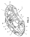
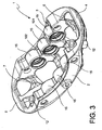
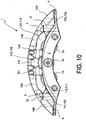
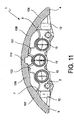
- a caliper body 1 for a disc brake is suitable for being arranged astride of a disc 40 for a disc brake.
- Said disc 40 has a first braking surface 41 and a second braking surface 42, opposite the first braking surface.
- the disc 40 defines an axial direction, indicated in the figures with the axis A-A, parallel to a rotation axis thereof, indicated in the figures with a-a, as well as a tangential or circumferential direction, indicated in the figures with T-T and parallel to one of its braking surfaces 41, 42.
- a disc-entry travel direction is defined, indicated in the figures with reference letter "I”, as well as defining an opposite disc exit direction indicated in the figures or in the references with "U”.
- Said disc 40 also defines a radial direction, indicated in the figures with R-R, arranged perpendicular to the axial direction A-A and to the circumferential or tangential direction T-T. Also for the radial direction it is possible to define a radial outward direction RO when this direction is followed away from the rotation axis of the disc a-a.
- the caliper body 1 comprises a mounting-side elongated portion 2, equipped with at least one mounting portion 12, for example but not necessarily a portion defining a through-hole suitable for receiving means for fixing the caliper body to a support structure of the caliper body, for example a stub axle of a suspension of a vehicle.
- Said mounting-side elongated portion 2 comprises a disc entry-side first tangential end 21 and a disc exit-side second tangential end 22.
- Said mounting-side elongated portion 2 has an axial inner surface thereof 13 suitable for facing the first braking surface 41 of the disc 40.
- Said mounting-side elongated portion 2 houses, or forms, three cylinders 15, suitable for each receiving a pressure on a pad 8 arranged, or housed, between said elongated mounting portion 2 and said braking surface 41 of the disc 40.
- Said caliper body 1 also comprises a non mounting-side elongated portion 3.
- Said non mounting-side elongated portion 3 has an axial inner surface 14 suitable for facing the second braking surface 42 of the disc 40.
- Said non mounting-side elongated portion has a disc entry-side first tangential end 23 and a disc exit-side second tangential end 24.
- Said non mounting-side elongated portion 3 houses, or forms, three cylinders 15, suitable for each receiving a piston to exert a pressure on a pad 9 housed between said non mounting-side elongated portion 3 of the caliper 39 and said braking surface 42 of the disc 40.
- Said elongated portions 2, 3 are connected together by a first end bridge 4 that connects the two disc entry-side tangential ends 21, 23 of the elongated mounting portion 2 and of the elongated non mounting portion 3.
- said bridge is suitable for being arranged astride of the disc 40.
- said end bridge 4 has a band-like or substantially flat body.
- Said elongated portions 2, 3 are also connected together by a second end bridge 5 that connects them at the two disc exit-side tangential ends 22, 24.
- Said second end bridge 5 is suitable for being arranged astride of the disc 40.
- said end bridge 5 has a band-like or substantially flat body.
- Said caliper body 1 also comprises further bridges, two central or middle bridges 101 and 102, and two intermediate bridges 6, 7 connecting the two elongated mounting and non mounting portions 2, 3 in their regions arranged inside or between the two end bridges, or else inside the disc entry-side first tangential end and the disc exit-side second end.
- said mounting-side and non mounting-side elongated portions 2, 3 are connected together by at least two bridges 5 and 7 or else 4 and 6 arranged circumferentially or tangentially outside the cylinders 15.
- said mounting-side and non mounting-side elongated portions 2,3 are connected together at both the disc entry and exit ends 21, 22, 23 and 24 by at least two bridges 5, 7 and 4, 6 for each end.
- each of said bridges 6, 7, 100 connects to said elongated portions at the side of said cylinders 15.
- every bridge at least those centrally arranged between said end bridges 4,5, connects to the elongated portion where it comprises a cylinder 15 and in particular on a side of a cylinder, for example engaging, in a radial view, at most half of the cylinder.
- the connection portion between a bridge 6, 7, 100 and the elongated portion comprising a cylinder 15 engages at most half of the body portion that forms the wall that defines a cylinder 15.
- each of said bridges 6, 7, 100 connects to said elongated portions at the side of said cylinders 15 so as not to radially cover more than half the cylinder.
- connection between a bridge and the elongated portion that is limited to the side of a cylinder, it is possible to leave at least one portion of an elongated element free, in particular a portion of the wall that defines a free cylinder, so as to facilitate the cooling of the wall that defines the chamber that receives the brake fluid for thrusting pistons received in said cylinder.
- said two bridges 101, 102 are adjacent without the interposition of cylinders.
- the non mounting side and mounting side elongated bodies 3, 2 define pockets 27 suitable for receiving the pads 8, 9 so that they are arranged between the pistons housed in the cylinders 15 and the braking surfaces 41, 42 of the disc 40 ( figure 8 ).
- the thickness evaluated in the tangential direction T-T of the central or middle bridges 101 and 102 is variable along the longitudinal or axial direction A-A of said central bridges 101, 102.
- At least one of the central bridges 6, 7 has a portion thereof close to the non mounting-side elongated element 3 equipped with a lightening undercut or groove 121 and 122.
- both of the central bridges 6, 7 have a portion close to the non mounting-side elongated element 3 equipped with a groove, for example but not necessarily longitudinal, or directed in the axial direction A-A, for lightening 121 and 122.
- the mounting-side and non mounting-side elongated portion 4, 3 have a longitudinal portion thereof extending according to the tangential direction T-T that is outside with respect to the body of the caliper 1, or on the opposite side with respect to the disc 40, with a low thickness or smaller than the thickness at the mounting points between the mounting-side and non mounting-side elongated portion 2, 3 and the end bridges 4, 5, as well as the intermediate and central bridges 6, 7; 101, 102.
- the mounting-side elongated portion 2 and the non mounting-side elongated portion 3, between at least one intermediate bridge 6, 7 and at least one central bridge 101, 102 have at least two recessed or undercut portions forming portions of said mounting-side elongated portion 2 and said non mounting-side elongated portion 3 with low thickness or smaller than the radial thickness evaluated at said intermediate bridge 6, 7 and said central bridge 101, 102.
- said window in said mounting-side elongated portion 2 and in said non mounting-side elongated portion 3, there are at least one window that opens in the axial direction A-A arranged between at least one bridge and the adjacent bridge, said window placing the inside of the body of the caliper, or a plate of the pad 8, in communication in the axial direction with the outside of the caliper.
- the non mounting-side elongated element 3 has a radial thickness outside of the shape of the cylinders that remains substantially constant along its entire longitudinal extension or parallel to the circumferential direction T-T.
- said non mounting-side elongated element 3 extends outside of the shape of the cylinders with a constant thickness forming an arc of circle-shaped portion, from which, for example, but not necessarily, at the bottom, i.e. in its side facing towards the axis of the disc a-a, portions project at the cylinders 15 to house the pistons for biasing the pad 9.
- every undercut portion or axial window of the mounting-side elongated portion 2 is axially faced by a portion of similar radial thickness of the non mounting-side elongated portion 3.
- the mounting-side elongated portion 2 has an upper surface thereof facing radially outwards with respect to the axis of the disc a-a, which is shaped following the profile of the cylinders 15 that are made in it, forming for example recessed and projecting loops.
- the mounting-side elongated portion 2 has a lower surface thereof facing radially inwards towards the axis of the disc a-a, shaped following the profile of the cylinders that are made in it, forming for example recessed and projecting loops.
- the mounting portions 12 foreseen in the mounting-side elongated portion 2 of the caliper 39 are two in number, or, alternatively, but not necessarily, there are four of them, where two of said four mounting portions 12 are preferably, but not necessarily arranged close to the intermediate bridges 6, 7.
- the mounting portions 12 are foreseen in accordance with an embodiment, close to the intermediate bridges 6, 7 all of the stresses coming from the non mounting-side elongated portion 3 are transferred to the support of the caliper passing through the intermediate bridges 6, 7 coming together directly through the mounting portions 12 to the connection means and to the support of the caliper, limiting the deformation of the body of the caliper 1.
- said non mounting-side elongated portion 3 has a radially upper surface facing in the radial outward direction away from the axis of the disc a-a and is shaped so as to follow the progression of the cylinders 15 foreseen in said non mounting-side elongated portion 3, forming for example recessed or projecting loops.
- said non mounting-side elongated portion 3 has an inner radial surface facing towards the axis of the disc a-a, shaped so as to follow the profile of the cylinders 15, foreseen in said non mounting-side elongated portion 3, forming for example recessed or projecting loops.
- a caliper body 1 for a disc brake is suitable for being arranged astride of a disc 40 for a disc brake.
- Said disc 40 comprises a first braking surface 41 and a second braking surface 42 opposite the first.
- Said disc 40 defines an axial direction A-A parallel to a rotation axis thereof a-a, the latter defining an axial outward direction AO when facing away from the vehicle, a tangential or circumferential direction T-T parallel to one of its braking surfaces, the latter defining an outward tangential direction TO when facing away from the caliper body, with disc entry direction I and disc exit direction U, and a radial direction R-R perpendicular to the axial direction A-A and to the circumferential or tangential direction T-T, the latter defining a radial outward direction RO when facing away from the rotation axis of the disc.
- Said caliper body comprises a mounting-side elongated portion 2 equipped with at least one mounting portion 12 suitable for being connected to a support for the caliper.
- Said mounting-side elongated portion 2 comprises a disc entry-side first tangential end 21 and a disc exit-side second tangential end 22.
- Said mounting-side elongated portion 2 is suitable for facing with an axial inner surface thereof 13 towards the first braking surface 41 of the disc.
- Said body also comprises a non mounting-side elongated portion 3 facing with an axial inner surface thereof 14 towards the second braking surface 42 of the disc and comprises a disc entry-side first tangential end 23 and a disc exit-side second end 24.
- Each elongated portion 2, 3 houses or forms at least two cylinders 15 each suitable for receiving a piston to exert a pressure on at least one pad 8, 9 housed between said elongated portion 2, 3 of the caliper 1 and said braking surface 41, 42 of the disc 40.
- Said elongated portions 2, 3 are connected together by a first end bridge 4 that connects the two disc entry-side tangential ends 21, 23.
- Said bridge is suitable for being arranged astride of the disc.
- Said elongated portions 2, 3 are connected by a second end bridge 5 that connects the two disc exit-side tangential ends 22, 24, said second bridge being suitable for being arranged astride of the disc.
- Said caliper body also comprises central bridges at the end bridges 6, 7, 100 connecting the two elongated portions 2, 3 in their regions arranged inside the two end bridges 4, 5.
- Each of said central bridges 6, 7, 100 connects to said elongated portions at the side of said cylinders 15 forming at least four through-windows in said caliper body 1.
- said caliper body 1 comprises four central bridges 6, 7, 101, 102, in particular two intermediate bridges 6, 7 and two middle or central bridges 101, 102, said bridges being arranged in to connect the two elongated portions 2, 3 in their regions arranged inside the two end bridges 4, 5.
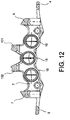
- Each of said central bridges 6, 7, 101, 102 at the end bridges connects to said elongated portions at the side of three cylinders 15 foreseen for each elongated portion 2, 3, together with the elongated portions 2, 3 forming at least five windows 111, 113, 115, 117, 119 passing through said caliper body 1.
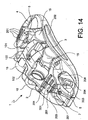
- each bridge 4, 5, 6, 7, 101, 102 connecting between said elongated portions 2, 3 comprises a first joining portion 103 joined to the mounting-side elongated portion 2 arranged substantially in the radial direction R-R, a second joining portion 104 joined to the non mounting-side elongated portion 3 arranged substantially in the radial direction R-R, a third bridge portion 105 joined to the first joining portion 103 and to the second joining portion 104 and arranged substantially in the axial direction A-A.
- At least two bridges 4, 5, 6, 7, 101, 102 are connected to the adjacent bridge through a further bridge transversal to it or tangential bridge 106, 107, 108, 109, 110 that, between the bridge and the adjacent bridge, defines two windows 111, 112; 113, 114; 115, 116; 117, 118; 119, 120 passing through the body of the caliper 1.
- an entry-side tangential bridge 106 that forms a mounting-side disc entry bridge window 111 and a non mounting-side disc entry bridge window 112.
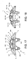
- said entry-side tangential bridge 106 is substantially V-shaped when observed in the radial direction. In accordance with an embodiment, said entry-side tangential bridge 106 is substantially V-shaped with rounded edges. In accordance with an embodiment, said entry-side tangential bridge 106 has, for example radially outside, grooves 201, for example but not necessarily extending in the axial direction A-A, for example but not necessarily a plurality of grooves 201 that are parallel to one another.
- an intermediate tangential bridge 108 that forms a window between intermediate bridge and central bridge on the mounting side 113 and a window between intermediate bridge and central bridge on the non mounting side 114.
- central bridge 101 between the central bridge 101 and an adjacent further central bridge 102 there is a central tangential bridge 110 that forms a window between central bridge and central bridge on the mounting side 115 and a window between central bridge and central bridge on the non mounting side 116.
- an intermediate tangential bridge 109 that forms a window between central bridge and intermediate bridge on the mounting side 117 and a window between central bridge and intermediate bridge on the non mounting side 118.
- a tangential end bridge 107 that forms a window between intermediate bridge and disc exit-side bridge on the mounting side 119 and a window between intermediate bridge and disc exit-side bridge on the non mounting side 120.
- said exit-side tangential bridge 107 is substantially V-shaped when observed in the radial direction. In accordance with an embodiment, said exit-side tangentiai bridge 107 is substantially V-shaped with rounded edges. In accordance with an embodiment, said exit-side tangential bridge 107 has, for example radially on the outside, grooves 201, ad for example but not necessarily extending in the axial direction A-A, for example but not necessarily a plurality of grooves 201 that are parallel to one another.
- two adjacent bridges 4, 6; 6, 101; 101, 102; 102, 7; 7, 5 define a through-window 120 and 119; 118 and 117; 116 and 115; 114 and 113; 112 and 111 that crosses the caliper body 1 in the axial direction A-A.
- said end bridges 4 and 5 have a foil-shaped bridge body that lies substantially parallel to a plane P.
- the end bridges 4 and 5 lie substantially parallel to the same plane P and advantageously are aligned with one another.
- said mounting-side elongated portion 2 and said non mounting-side elongated portion 3 extend in the tangential direction T-T substantially in an arc of circle housing or forming the cylinders 15.
- said cylinders project from said mounting-side elongated portion 2 and said non mounting-side elongated portion 3 in the radial outward direction RO and in the opposite radial direction.
- said non mounting-side elongated portion 3 externally or axially externally has a groove 201 extending tangentially.
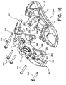
- said mounting-side elongated portion 2 has at least one, preferably two, connection brackets 203 for the connection of the caliper to a stub axle.
- said connection brackets 203 extend in a substantially radial direction and, for example but not necessarily, at the end form seats 204 for the connection of the caliper to the stub axle, for example but not necessarily, seats extending in a substantially axial direction.
- two central bridges 101 and 102 are connected together by a central tangential bridge 110 directed tangentially T-T and together with said central bridges 101, 102 defining two through-windows 115, 116 that in the radial direction R-R have an edge curved in a bulb.
- tangential bridge directed tangentially T-T that together with said central and intermediate bridges 101, 102; 6, 7 defines two through-windows 113, 114; 117, 118 that in the radial direction R-R have a U-shaped edge with a flat base towards the elongated body 2, 3.
- a tangential bridge directed tangentially T-T that together with said intermediate and end bridges 6, 7; 4, 5 defines two through-windows 111, 112; 119, 120 that in the radial direction R-R have a triangular edge with the side facing the edge of the intermediate bridge curved towards the end bridges.
- said intermediate bridges 6, 7 house or form mounting portions 12 of the caliper body to the stub axle.
- said central bridges 101 and 102 have a portion that projects to the non mounting-side elongated portion 3 with a radially outer surface in which a lightening groove 121, 122 is formed.
- said mounting-side and non mounting-side elongated portions 2, 3 each house or form three cylinders 15 and are connected together by six bridges 4, 5, 6, 7, 101, 102 and each pair of adjacent bridges is connected by tangential bridges 106, 107, 108, 109, 110, defining ten through-windows in the radial direction to the caliper body.
- said mounting-side and non mounting-side elongated portions 2, 3 each house or form three cylinders 15 and are connected together by six bridges 4, 5, 6, 7, 101, 102 and each pair of adjacent bridges is connected by tangential bridges 106, 107, 108, 109, 110, defining ten through-windows in the axial direction to the caliper body.
- said caliper body 1 is a monoblock or a body in a single piece.
- inverted U-shaped bridges it is possible to drastically reduce the weight of the caliper and, at the same time, to drastically limit the deformation of the body of the caliper during the braking actions in both directions of travel of the vehicle. Thanks to the provision of a caliper body as described above, it is possible to obtain a structure that is particularly resistant to the high stresses generated by sudden braking, for example like in racing vehicles.
- the caliper biased with the maximum braking will have an extremely small deformation that avoids undesired strokes of the brake pedal lever, giving the user the sensation of extremely good responsivity of the braking system.
- the overall weight of the caliper is low.
- the caliper displays an increased rigidity of 2-4% and even of 8-9% with respect to a caliper not equipped with intermediate bridges and at least one central bridge, together with a weight reduction of about 5-8%.
Landscapes
- Engineering & Computer Science (AREA)
- General Engineering & Computer Science (AREA)
- Mechanical Engineering (AREA)
- Braking Arrangements (AREA)
Claims (16)
- Sattelkörper (1) für eine Scheibenbremse, der zum Anordnen über einer Scheibe (40) pro Scheibenbremse geeignet ist,wobei die Scheibe (40) eine erste Bremsoberfläche (41) und eine der ersten entgegengesetzte zweite Bremsoberfläche (42) aufweist;wobei die Scheibe (40) definiert: eine Achsrichtung (A-A) parallel zu ihrer Drehachse (a-a), wobei die letztere eine bei Betrachtung vom Fahrzeug weg axial auswärtige Richtung (AO) definiert, eine tangentiale oder Umfangsrichtung (T-T) parallel zu einer ihrer Bremsoberflächen, wobei die letztere bei Betrachtung vom Sattelkörper weg eine tangential auswärtige Richtung (TO) definiert, mit einer Scheibeneintrittsrichtung (I) und einer Scheibenaustrittsrichtung (U), sowie eine radiale Richtung (R-R) senkrecht zur Achsrichtung (A-A) und zur tangentialen oder Umfangsrichtung (T-T), wobei die Letztere bei Betrachtung von der Drehachse der Scheibe weg eine radial auswärtige Richtung (RO) definiert;wobei der Sattelkörper umfasst:
einen länglichen montageseitigen Abschnitt (2), der mit zumindest einem Montageabschnitt (12) ausgestattet ist, der zur Verbindung mit einem Träger für den Sattel geeignet ist;wobei der längliche montageseitige Abschnitt (2) ein scheibeneintrittsseitiges erstes tangentiales Ende (21) und ein scheibenaustrittsseitiges zweites tangentiales Ende (22) aufweist;wobei der längliche montageseitige Abschnitt (2) dafür geeignet ist, mit seiner axialen Innenoberfläche (13) zur ersten Bremsoberfläche (41) der Scheibe zu weisen;wobei der Körper auch einen nicht-montageseitigen länglichen Abschnitt (3) aufweist, der mit seiner axialen Innenoberfläche (14) zu der zweiten Bremsoberfläche (42) der Scheibe weist und ein scheibeneintrittsseitiges tangentiales Ende (23) und ein scheibenaustrittsseitiges zweites Ende (24) aufweist;wobei jeder längliche Abschnitt (2, 3) zumindest zwei Zylinder (15) aufnimmt oder bildet, die jeweils zur Aufnahme eines Kolbens geeignet sind, um einen Druck auf zumindest einen Belag (8, 9) auszuüben, der zwischen dem länglichen Abschnitt (2, 3) des Sattels (1) und der Bremsoberfläche (41, 42) der Scheibe (40) aufgenommen ist;wobei die länglichen Abschnitte (2, 3) durch eine erste Endbrücke (4) miteinander verbunden sind, welche die zwei scheibeneintrittsseitigen tangentialen Enden (21, 23) verbindet, wobei die Brücke zur Anordnung über der Scheibe geeignet ist;wobei die länglichen Abschnitte (2, 3) durch eine zweite Endbrücke (5) verbunden sind, die die zwei scheibenaustrittsseitigen tangentialen Enden (22, 24) verbindet, wobei die zweite Brücke zur Anordnung über der Scheibe geeignet ist;wobei der Sattelkörper (1) auch zumindest drei zentrale Brücken (6, 7, 100) aufweist, die die zwei länglichen Abschnitte (2, 3) in ihren innerhalb der zwei Endbrücken (4, 5) angeordneten Bereichen verbindet;worin jede der zentralen Brücken (6, 7, 100) mit den länglichen Abschnitten an der Seite der zumindest zwei Zylinder (15) verbunden ist, um nicht mehr als die Hälfte des Zylinders radial zu überdecken, und zumindest vier Fenster bildet, welche durch den Sattelkörper (1) hindurchgehen,worin zumindest zwei Brücken (4, 6 oder 5, 7), welche die länglichen Abschnitte (2, 3) verbinden, in den länglichen Abschnitten (2, 3) vorausschauend, tangential außerhalb der zumindest zwei Zylinder (15) angeordnet sind, zur Vermeidung, dass zwischen diesen Brücken (4, 6 oder 5, 7) Zylinder (15) vorhanden sind;und worin der Sattelkörper (1) ein Monoblock oder ein einstückiger Körper ist;dadurch gekennzeichnet, dass der Sattelkörper (1) vier zentrale Brücken (6, 7, 101, 102), zwei Zwischenbrücken (6, 7) und zwei mittlere Brücken (101, 102) aufweist, wobei die zentralen Brücken so angeordnet sind, dass sie die länglichen Abschnitte (2, 3) in ihren Bereichen verbinden, die innerhalb der zwei Endbrücken (4, 5) angeordnet sind; wobei jede der zentralen Brücken (6, 7, 101, 102), für jeden länglichen Abschnitt (2, 3) vorausschauend, mit den länglichen Abschnitten an den Seiten eines Zylinders (15) der drei Zylinder (15) verbunden sind, wobei sie zusammen mit den länglichen Abschnitten (2, 3) zumindest fünf Fenster bilden, welche durch den Sattelkörper (1) hindurchgehen. - Sattelkörper nach einem der vorhergehenden Ansprüche, worin jede Brücke (4, 5, 6, 7, 101, 102), welche eine Verbindung zwischen den länglichen Abschnitten (2, 3) bildet, umfasst:einen ersten Verbindungsabschnitt (103), der mit dem länglichen montageseitigen Abschnitt (2) verbunden ist, der im Wesentlichen in der radialen Richtung (R-R) angeordnet ist;einen zweiten Verbindungsabschnitt (104), der mit dem länglichen nicht-montageseitigen Abschnitt (3) verbunden ist, der im Wesentlichen in der radialen Richtung (R-R) angeordnet ist,einen dritten Brückenabschnitt (105), der mit dem ersten Verbindungsabschnitt (103) und mit dem zweiten Verbindungsabschnitt (104) verbunden ist und im Wesentlichen in der Achsrichtung (A-A) angeordnet ist,wobei die Abschnitte (103, 104 und 105) die Brücke im Wesentlichen in einem "U" konfigurieren, das zur Anordnung über der Scheibe (40) geeignet ist.
- Sattelkörper nach einem der vorhergehenden Ansprüche, worin jede Brücke (4, 5, 6, 7, 101, 102) mit der benachbarten Brücke durch eine zu ihr quer verlaufende weitere Brücke oder tangentiale Brücke (106, 107, 108, 109, 110) verbunden ist, die zwischen der Brücke und der benachbarten Brücke zwei Durchgangsfenster (111, 112, 113, 114, 115, 116, 117, 118, 119, 120) durch den Körper des Sattels (1) hindurch definiert.
- Sattelkörper nach Anspruch 3, worin zwischen einer Scheibeneintrittsbrücke (4) und einer benachbarten Zwischenbrücke (6) eine eintrittsseitige tangentiale Brücke (106) vorhanden ist, die ein montageseitiges Scheibeneintrittsbrückenfenster (111) und ein nicht-montageseitiges Scheibeneintrittsbrückenfenster (112) bildet;zwischen der Zwischenbrücke (6) und einer benachbarten zentralen Brücke (101) eine Zwischen-Tangentialbrücke (108) vorhanden ist, die ein Fenster zwischen der Zwischenbrücke und der zentralen Brücke an der Montageseite (113) und ein Fenster zwischen der Zwischenbrücke und der zentralen Brücke an der Nicht-Montageseite (114) bildet;zwischen der zentralen Brücke (101) und einer benachbarten zentralen Brücke (102) eine zentrale tangentiale Brücke (110) vorhanden ist, die ein Fenster zwischen der zentralen Brücke und der zentralen Brücke an der Montageseite (115) sowie ein Fenster zwischen der zentralen Brücke und der zentralen Brücke an der Nicht-Montageseite (116) bildet;zwischen der zentralen Brücke (102) und einer benachbarten Zwischenbrücke (7) eine Zwischen-Tangentialbrücke (109) vorhanden ist, die ein Fenster zwischen der zentralen Brücke und der Zwischenbrücke an der Montageseite (117) sowie ein Fenster zwischen der zentralen Brücke und der Zwischenbrücke an der Nicht-Montageseite (118) bildet;zwischen der Zwischenbrücke (107) und einer benachbarten austrittsseitigen Endbrücke (5) eine tangentiale Endbrücke (107) vorhanden ist, die ein Fenster zwischen der Zwischenbrücke und der scheibenaustrittsseitigen Brücke an der Montageseite (119) sowie ein Fenster zwischen der Zwischenbrücke und der scheibenaustrittsseitigen Brücke an der Nicht-Montageseite (120) bildet.
- Sattelkörper nach einem der vorhergehenden Ansprüche, worin zwei benachbarte Brücken (4, 6; 6, 101; 101, 102; 102, 7; 7, 5) ein Durchgangsfenster (120 und 119; 118 und 117; 116 und 115; 114 und 113; 112 und 111) definieren, das den Sattelkörper (1) in der axialen Richtung (A-A) durchsetzt.
- Sattelkörper nach einem der vorhergehenden Ansprüche, worin die Endbrücken (4 und 5) einen flügelförmigen Brückenkörper aufweisen, der im Wesentlichen parallel zu einer Ebene (P) liegt.
- Sattelköper nach einem der vorhergehenden Ansprüche, worin die Endbrücken (4 und 5) im Wesentlichen in der gleichen Ebene (P) liegen.
- Sattelköper nach einem der vorhergehenden Ansprüche, worin der längliche montageseitige Abschnitt (2) und der längliche nicht-montageseitige Abschnitt (3) sich in der tangentialen Richtung (T-T) im Wesentlichen auf einem Kreisbogen erstrecken, der die Zylinder (15) aufnimmt oder bildet, die von dem länglichen montageseitigen Abschnitt (2) und dem länglichen nicht-montageseitigen Abschnitt (3) in radial auswärtiger Richtung (RO) und in der entgegengesetzten radialen Richtung vorstehen.
- Sattelköper nach einem der vorhergehenden Ansprüche, worin zwei zentrale Brücken (101 und 102) durch eine zentrale tangentiale Brücke (110), die tangential (T-T) ausgerichtet ist, miteinander verbunden sind, und zusammen mit den zentralen Brücken (101, 102) zwei Durchgangsfenster (115, 116) definieren, die in der radialen Richtung (R-R) einen birnenförmig gekrümmten Rand aufweisen.
- Sattelköper nach einem der vorhergehenden Ansprüche, worin die Zwischenbrücken (6, 7) Montageabschnitte (12) des Sattelkörpers zum Achsschenkel aufnehmen oder bilden.
- Sattelköper nach einem der vorhergehenden Ansprüche, worin die zentralen Brücken (101 und 102) einen Abschnitt haben, der zu dem länglichen nicht-montageseitigen Abschnitt (3) vorsteht, mit einer radialen Außenoberfläche, in der eine Erleichterungsnut (121, 122) ausgebildet ist.
- Sattelköper nach einem der vorhergehenden Ansprüche, worin die länglichen montageseitigen und nicht-montageseitigen Abschnitte (2, 3) jeweils drei Zylinder (15) aufnehmen oder bilden und sie durch sechs Brücken (4, 5, 6, 7, 101, 102) und durch tangentiale Brücken (106, 107, 108, 109, 110) miteinander verbunden sind, die zehn Durchgangsfenster in der radialen Richtung zum Sattelkörper und in der axialen Richtung zum Sattelkörper definieren.
- Sattelköper nach einem der vorhergehenden Ansprüche, worin zwischen den zumindest zwei Zylindern (15) für den länglichen Abschnitt (2, 3) zwei benachbarte Brücken (101, 102) ohne den Einbau von Zylindern zwischen diesen vorhanden sind.
- Sattelköper nach dem vorhergehenden Anspruch, worin zwischen den zumindest zwei Brücken (101, 102) zumindest eine sich tangential erstreckende Brücke (110) vorhanden ist.
- Sattelköper nach einem der vorhergehenden Ansprüche, worin zwischen einer Scheibeneintrittsbrücke (4 oder 5) und einer benachbarten Zwischenbrücke (6 oder 7) eine tangentiale Brücke (106 oder 107) vorhanden ist, die in der radialen Richtung im Wesentlichen V-förmig ist, und/oder worin die tangentiale Brücke (106 oder 107) im Wesentlichen V-förmig mit gerundeten Rändern ist.
- Sattel für eine Bremsscheibe, der einen Sattelkörper aufweist, wie er in einem der vorhergehenden Ansprüche beschrieben ist.
Applications Claiming Priority (2)
| Application Number | Priority Date | Filing Date | Title |
|---|---|---|---|
| ITMI2010A000537A IT1399203B1 (it) | 2010-03-31 | 2010-03-31 | Corpo pinza di un freno a disco |
| PCT/IB2011/051351 WO2011121553A1 (en) | 2010-03-31 | 2011-03-30 | Caliper body of a disc brake |
Publications (4)
| Publication Number | Publication Date |
|---|---|
| EP2553289A1 EP2553289A1 (de) | 2013-02-06 |
| EP2553289B1 EP2553289B1 (de) | 2015-01-14 |
| EP2553289B9 EP2553289B9 (de) | 2017-04-12 |
| EP2553289B2 true EP2553289B2 (de) | 2021-09-01 |
Family
ID=43037615
Family Applications (1)
| Application Number | Title | Priority Date | Filing Date |
|---|---|---|---|
| EP11717762.6A Active EP2553289B2 (de) | 2010-03-31 | 2011-03-30 | Bremssattelkörper einer scheibenbremse |
Country Status (5)
| Country | Link |
|---|---|
| US (1) | US9291224B2 (de) |
| EP (1) | EP2553289B2 (de) |
| CN (1) | CN102906444B (de) |
| IT (1) | IT1399203B1 (de) |
| WO (1) | WO2011121553A1 (de) |
Families Citing this family (40)
| Publication number | Priority date | Publication date | Assignee | Title |
|---|---|---|---|---|
| ITTO20120140A1 (it) * | 2012-02-16 | 2013-08-17 | Freni Brembo Spa | Corpo pinza per freni a disco |
| ITMI20132215A1 (it) * | 2013-12-30 | 2015-07-01 | Freni Brembo Spa | Corpo pinza di un freno a disco |
| USD790417S1 (en) * | 2014-08-05 | 2017-06-27 | Freni Brembo S.P.A. | Disc brake calliper body |
| JP6446275B2 (ja) * | 2015-01-19 | 2018-12-26 | 曙ブレーキ工業株式会社 | 対向ピストン型ディスクブレーキ用キャリパ |
| CN104747623A (zh) * | 2015-04-10 | 2015-07-01 | 江苏佰瑞克汽配有限公司 | 一种汽车盘式制动器连接桥 |
| USD785520S1 (en) * | 2015-07-20 | 2017-05-02 | Freni Brembo S.P.A. | Disc brake calliper |
| ITUB20155107A1 (it) * | 2015-11-02 | 2017-05-02 | Freni Brembo Spa | Corpo pinza di freno a disco |
| USD805012S1 (en) * | 2015-11-17 | 2017-12-12 | Freni Brembo S.P.A | Disc brake caliper |
| ITUB20155653A1 (it) * | 2015-11-17 | 2017-05-17 | Freni Brembo Spa | Pinza per freno a disco, metodo di fabbricazione di una pinza e molla per pinza |
| ITUB20159801A1 (it) * | 2015-12-30 | 2017-06-30 | Freni Brembo Spa | Corpo pinza di freno a disco |
| USD804375S1 (en) * | 2016-05-17 | 2017-12-05 | Freni Brembo S.P.A. | Disc brake caliper |
| USD892007S1 (en) * | 2016-06-30 | 2020-08-04 | Freni Brembo S.P.A. | Disc brake calliper |
| USD862327S1 (en) * | 2016-06-30 | 2019-10-08 | Freni Brembo S.P.A. | Disc brake calliper |
| USD861559S1 (en) | 2016-06-30 | 2019-10-01 | Freni Brembo S.P.A. | Disc brake calliper |
| TWD186984S (zh) * | 2016-07-08 | 2017-12-01 | 佛雷尼布蘭柏股份有限公司 | 碟煞卡鉗 |
| USD856229S1 (en) | 2016-08-02 | 2019-08-13 | Akebono Brake Industry Co., Ltd. | Caliper body of a disc brake for vehicles |
| USD831551S1 (en) | 2016-08-30 | 2018-10-23 | Akebono Brake Industry Co., Ltd | Brake caliper |
| JP6794238B2 (ja) * | 2016-12-09 | 2020-12-02 | 曙ブレーキ工業株式会社 | 対向ピストン型ディスクブレーキ用キャリパ |
| TWD193554S (zh) * | 2016-12-19 | 2018-10-21 | A P 賽車股份有限公司 | 碟剎卡鉗 |
| IT201600130165A1 (it) * | 2016-12-22 | 2018-06-22 | Freni Brembo Spa | Corpo pinza per freno a disco, pinza freno e freno a disco |
| US10280995B2 (en) | 2017-01-05 | 2019-05-07 | Akebono Brake Industry Co., Ltd | Reinforced caliper housing |
| US10539199B2 (en) | 2017-01-20 | 2020-01-21 | Akebono Brake Industry Co., Ltd | Multi-piston caliper |
| US20180363717A1 (en) | 2017-06-14 | 2018-12-20 | Akebono Brake Industry Co., Ltd | Hollow bridge caliper with filled core |
| JP6871829B2 (ja) * | 2017-09-06 | 2021-05-12 | 曙ブレーキ工業株式会社 | 対向ピストン型ディスクブレーキ用キャリパ |
| DE202017107807U1 (de) | 2017-12-21 | 2018-02-05 | Akebono Brake Industry Co., Ltd. | Mehrkolben-Bremssattel |
| DE202018100060U1 (de) | 2018-01-05 | 2018-01-22 | Akebono Brake Industry Co., Ltd. | Verstärktes Bremssattelgehäuse |
| IT201800006547A1 (it) * | 2018-06-21 | 2019-12-21 | Corpo pinza di freno a disco | |
| USD902097S1 (en) * | 2018-10-15 | 2020-11-17 | Wooshin Industries Co., Ltd. | Disk brake caliper for automobile |
| US10948035B2 (en) * | 2018-11-29 | 2021-03-16 | Advics Co., Ltd. | Brake half-caliper and method of making brake half-caliper |
| IT201800020251A1 (it) * | 2018-12-20 | 2020-06-20 | Freni Brembo Spa | Corpo pinza e pinza freno con detto corpo |
| USD938871S1 (en) * | 2019-11-01 | 2021-12-21 | Mando Corporation | Disc brake caliper for vehicle |
| USD991857S1 (en) * | 2021-03-19 | 2023-07-11 | Brembo S.P.A. | Caliper for disc brake |
| USD991856S1 (en) * | 2021-03-19 | 2023-07-11 | Brembo S.P.A. | Caliper for disc brake |
| USD992472S1 (en) * | 2021-04-23 | 2023-07-18 | Wooshin Industries Co., Ltd | Monoblock brake caliper |
| WO2023064269A1 (en) * | 2021-10-11 | 2023-04-20 | Lewis Designs, LLC | Sphere braking system with slide-in brake pads |
| USD1044636S1 (en) * | 2021-12-24 | 2024-10-01 | A.P. Racing Ltd | Brake caliper |
| JP1734899S (ja) * | 2022-03-21 | 2023-01-18 | ブレーキディスク用キャリパー | |
| IT202200006218A1 (it) | 2022-03-30 | 2023-09-30 | Brembo Spa | Corpo pinza per pinza freno, pinza freno e freno a disco |
| USD1042270S1 (en) * | 2022-05-05 | 2024-09-17 | Nio Co., Ltd. | Braking caliper used for braking wheels of automobile |
| IT202200012473A1 (it) * | 2022-06-13 | 2023-12-13 | Brembo Spa | Corpo pinza di pinza freno e pinza freno |
Family Cites Families (13)
| Publication number | Priority date | Publication date | Assignee | Title |
|---|---|---|---|---|
| GB1050263A (de) | 1962-12-28 | |||
| US4512317A (en) | 1984-02-27 | 1985-04-23 | Allied Corporation | Extended range throttle body fuel injection system |
| JPH09257063A (ja) | 1996-03-21 | 1997-09-30 | Aisin Seiki Co Ltd | 車両用ディスクブレーキ |
| ES2284673T3 (es) | 2000-06-07 | 2007-11-16 | Lucas Automotive Gmbh | Pinza flotante para un freno de disco y freno de disco. |
| ITTO20020248A1 (it) * | 2001-03-21 | 2003-09-22 | Tokico Ltd | Freno a disco. |
| US20070170020A1 (en) * | 2004-02-13 | 2007-07-26 | Continental Teves Ag & Co. Ohg | Floating-caliper disk brake, especially for high braking power |
| DE102007006472A1 (de) * | 2006-04-20 | 2007-11-08 | Continental Teves Ag & Co. Ohg | Scheibenbremse |
| US20070278049A1 (en) * | 2006-06-05 | 2007-12-06 | Akebono Brake Industry Co., Ltd. | Opposed piston type disc brake |
| GB0617474D0 (en) * | 2006-09-06 | 2006-10-18 | A P Racing Ltd | A disc brake caliper and a method of manufacturing a disc brake caliper |
| ITMI20061973A1 (it) * | 2006-10-13 | 2008-04-14 | Freni Brembo Spa | Pinza per freno a disco |
| DE102006052177A1 (de) * | 2006-11-02 | 2008-05-08 | Continental Teves Ag & Co. Ohg | Scheibenbremse und Betätigungsvorrichtung dafür |
| GB2451690B (en) * | 2007-08-10 | 2009-08-05 | Ap Racing Ltd | A disc brake caliper body and a disc brake caliper comprising such a body |
| DE102008029582A1 (de) * | 2007-10-19 | 2009-04-23 | Continental Teves Ag & Co. Ohg | Scheibenbremse |
-
2010
- 2010-03-31 IT ITMI2010A000537A patent/IT1399203B1/it active
-
2011
- 2011-03-30 CN CN201180024540.8A patent/CN102906444B/zh not_active Expired - Fee Related
- 2011-03-30 EP EP11717762.6A patent/EP2553289B2/de active Active
- 2011-03-30 US US13/637,995 patent/US9291224B2/en active Active
- 2011-03-30 WO PCT/IB2011/051351 patent/WO2011121553A1/en not_active Ceased
Also Published As
| Publication number | Publication date |
|---|---|
| CN102906444A (zh) | 2013-01-30 |
| EP2553289A1 (de) | 2013-02-06 |
| EP2553289B1 (de) | 2015-01-14 |
| WO2011121553A1 (en) | 2011-10-06 |
| US9291224B2 (en) | 2016-03-22 |
| CN102906444B (zh) | 2016-06-08 |
| IT1399203B1 (it) | 2013-04-11 |
| US20130092481A1 (en) | 2013-04-18 |
| EP2553289B9 (de) | 2017-04-12 |
| ITMI20100537A1 (it) | 2011-10-01 |
Similar Documents
| Publication | Publication Date | Title |
|---|---|---|
| EP2553289B1 (de) | Bremssattelkörper einer scheibenbremse | |
| EP2516879B1 (de) | Bremssattelkörper einer scheibenbremse | |
| EP2591248B1 (de) | Bremssattelkörper einer scheibenbremse | |
| EP3087291B1 (de) | Scheibenbremssattelkörper und scheibenbremssattel | |
| EP2635823B1 (de) | Anordnung eines bremssattels einer scheibenbremse und nabenklammer | |
| EP2435722B1 (de) | Sattelkörper | |
| US11821476B2 (en) | Disc brake caliper body | |
| JP4067689B2 (ja) | 対向ピストン型ディスクブレーキ | |
| JP6794238B2 (ja) | 対向ピストン型ディスクブレーキ用キャリパ | |
| US7234568B2 (en) | High performance disk brake | |
| JP7384744B2 (ja) | 対向ピストン型ディスクブレーキ用キャリパ | |
| CN113272570A (zh) | 卡钳本体和具有所述本体的制动器卡钳 | |
| US12385534B2 (en) | Caliper body and brake caliper with said body | |
| JP4818307B2 (ja) | ラジアルマウント式車両用ディスクブレーキ | |
| JP7845908B2 (ja) | 対向ピストン型ディスクブレーキ用キャリパ | |
| JPH06235431A (ja) | 車両用ディスクブレーキのキャリパボディ取付け構造 |
Legal Events
| Date | Code | Title | Description |
|---|---|---|---|
| PUAI | Public reference made under article 153(3) epc to a published international application that has entered the european phase |
Free format text: ORIGINAL CODE: 0009012 |
|
| 17P | Request for examination filed |
Effective date: 20120927 |
|
| AK | Designated contracting states |
Kind code of ref document: A1 Designated state(s): AL AT BE BG CH CY CZ DE DK EE ES FI FR GB GR HR HU IE IS IT LI LT LU LV MC MK MT NL NO PL PT RO RS SE SI SK SM TR |
|
| RIN1 | Information on inventor provided before grant (corrected) |
Inventor name: PREDA, MASSIMO Inventor name: CESANI, PAOLO Inventor name: CRIPPA, CRISTIAN |
|
| DAX | Request for extension of the european patent (deleted) | ||
| GRAP | Despatch of communication of intention to grant a patent |
Free format text: ORIGINAL CODE: EPIDOSNIGR1 |
|
| INTG | Intention to grant announced |
Effective date: 20130919 |
|
| GRAS | Grant fee paid |
Free format text: ORIGINAL CODE: EPIDOSNIGR3 |
|
| GRAP | Despatch of communication of intention to grant a patent |
Free format text: ORIGINAL CODE: EPIDOSNIGR1 |
|
| INTG | Intention to grant announced |
Effective date: 20140618 |
|
| RIN1 | Information on inventor provided before grant (corrected) |
Inventor name: CESANI, PAOLO Inventor name: PREDA, MASSIMO Inventor name: CRIPPA, CRISTIAN |
|
| INTG | Intention to grant announced |
Effective date: 20140623 |
|
| GRAS | Grant fee paid |
Free format text: ORIGINAL CODE: EPIDOSNIGR3 |
|
| GRAA | (expected) grant |
Free format text: ORIGINAL CODE: 0009210 |
|
| AK | Designated contracting states |
Kind code of ref document: B1 Designated state(s): AL AT BE BG CH CY CZ DE DK EE ES FI FR GB GR HR HU IE IS IT LI LT LU LV MC MK MT NL NO PL PT RO RS SE SI SK SM TR |
|
| REG | Reference to a national code |
Ref country code: GB Ref legal event code: FG4D |
|
| REG | Reference to a national code |
Ref country code: CH Ref legal event code: EP |
|
| REG | Reference to a national code |
Ref country code: IE Ref legal event code: FG4D |
|
| REG | Reference to a national code |
Ref country code: AT Ref legal event code: REF Ref document number: 707234 Country of ref document: AT Kind code of ref document: T Effective date: 20150215 |
|
| REG | Reference to a national code |
Ref country code: DE Ref legal event code: R096 Ref document number: 602011013136 Country of ref document: DE Effective date: 20150226 |
|
| REG | Reference to a national code |
Ref country code: FR Ref legal event code: PLFP Year of fee payment: 5 |
|
| REG | Reference to a national code |
Ref country code: NL Ref legal event code: VDEP Effective date: 20150114 |
|
| REG | Reference to a national code |
Ref country code: AT Ref legal event code: MK05 Ref document number: 707234 Country of ref document: AT Kind code of ref document: T Effective date: 20150114 |
|
| REG | Reference to a national code |
Ref country code: LT Ref legal event code: MG4D |
|
| PG25 | Lapsed in a contracting state [announced via postgrant information from national office to epo] |
Ref country code: LT Free format text: LAPSE BECAUSE OF FAILURE TO SUBMIT A TRANSLATION OF THE DESCRIPTION OR TO PAY THE FEE WITHIN THE PRESCRIBED TIME-LIMIT Effective date: 20150114 Ref country code: SE Free format text: LAPSE BECAUSE OF FAILURE TO SUBMIT A TRANSLATION OF THE DESCRIPTION OR TO PAY THE FEE WITHIN THE PRESCRIBED TIME-LIMIT Effective date: 20150114 Ref country code: FI Free format text: LAPSE BECAUSE OF FAILURE TO SUBMIT A TRANSLATION OF THE DESCRIPTION OR TO PAY THE FEE WITHIN THE PRESCRIBED TIME-LIMIT Effective date: 20150114 Ref country code: HR Free format text: LAPSE BECAUSE OF FAILURE TO SUBMIT A TRANSLATION OF THE DESCRIPTION OR TO PAY THE FEE WITHIN THE PRESCRIBED TIME-LIMIT Effective date: 20150114 Ref country code: ES Free format text: LAPSE BECAUSE OF FAILURE TO SUBMIT A TRANSLATION OF THE DESCRIPTION OR TO PAY THE FEE WITHIN THE PRESCRIBED TIME-LIMIT Effective date: 20150114 Ref country code: BG Free format text: LAPSE BECAUSE OF FAILURE TO SUBMIT A TRANSLATION OF THE DESCRIPTION OR TO PAY THE FEE WITHIN THE PRESCRIBED TIME-LIMIT Effective date: 20150414 Ref country code: NO Free format text: LAPSE BECAUSE OF FAILURE TO SUBMIT A TRANSLATION OF THE DESCRIPTION OR TO PAY THE FEE WITHIN THE PRESCRIBED TIME-LIMIT Effective date: 20150414 |
|
| PG25 | Lapsed in a contracting state [announced via postgrant information from national office to epo] |
Ref country code: NL Free format text: LAPSE BECAUSE OF FAILURE TO SUBMIT A TRANSLATION OF THE DESCRIPTION OR TO PAY THE FEE WITHIN THE PRESCRIBED TIME-LIMIT Effective date: 20150114 Ref country code: IS Free format text: LAPSE BECAUSE OF FAILURE TO SUBMIT A TRANSLATION OF THE DESCRIPTION OR TO PAY THE FEE WITHIN THE PRESCRIBED TIME-LIMIT Effective date: 20150514 Ref country code: AT Free format text: LAPSE BECAUSE OF FAILURE TO SUBMIT A TRANSLATION OF THE DESCRIPTION OR TO PAY THE FEE WITHIN THE PRESCRIBED TIME-LIMIT Effective date: 20150114 Ref country code: GR Free format text: LAPSE BECAUSE OF FAILURE TO SUBMIT A TRANSLATION OF THE DESCRIPTION OR TO PAY THE FEE WITHIN THE PRESCRIBED TIME-LIMIT Effective date: 20150415 Ref country code: LV Free format text: LAPSE BECAUSE OF FAILURE TO SUBMIT A TRANSLATION OF THE DESCRIPTION OR TO PAY THE FEE WITHIN THE PRESCRIBED TIME-LIMIT Effective date: 20150114 Ref country code: PL Free format text: LAPSE BECAUSE OF FAILURE TO SUBMIT A TRANSLATION OF THE DESCRIPTION OR TO PAY THE FEE WITHIN THE PRESCRIBED TIME-LIMIT Effective date: 20150114 Ref country code: RS Free format text: LAPSE BECAUSE OF FAILURE TO SUBMIT A TRANSLATION OF THE DESCRIPTION OR TO PAY THE FEE WITHIN THE PRESCRIBED TIME-LIMIT Effective date: 20150114 |
|
| REG | Reference to a national code |
Ref country code: DE Ref legal event code: R026 Ref document number: 602011013136 Country of ref document: DE |
|
| PLBI | Opposition filed |
Free format text: ORIGINAL CODE: 0009260 |
|
| PG25 | Lapsed in a contracting state [announced via postgrant information from national office to epo] |
Ref country code: DK Free format text: LAPSE BECAUSE OF FAILURE TO SUBMIT A TRANSLATION OF THE DESCRIPTION OR TO PAY THE FEE WITHIN THE PRESCRIBED TIME-LIMIT Effective date: 20150114 Ref country code: RO Free format text: LAPSE BECAUSE OF FAILURE TO SUBMIT A TRANSLATION OF THE DESCRIPTION OR TO PAY THE FEE WITHIN THE PRESCRIBED TIME-LIMIT Effective date: 20150114 Ref country code: LU Free format text: LAPSE BECAUSE OF FAILURE TO SUBMIT A TRANSLATION OF THE DESCRIPTION OR TO PAY THE FEE WITHIN THE PRESCRIBED TIME-LIMIT Effective date: 20150330 Ref country code: EE Free format text: LAPSE BECAUSE OF FAILURE TO SUBMIT A TRANSLATION OF THE DESCRIPTION OR TO PAY THE FEE WITHIN THE PRESCRIBED TIME-LIMIT Effective date: 20150114 Ref country code: CZ Free format text: LAPSE BECAUSE OF FAILURE TO SUBMIT A TRANSLATION OF THE DESCRIPTION OR TO PAY THE FEE WITHIN THE PRESCRIBED TIME-LIMIT Effective date: 20150114 Ref country code: SK Free format text: LAPSE BECAUSE OF FAILURE TO SUBMIT A TRANSLATION OF THE DESCRIPTION OR TO PAY THE FEE WITHIN THE PRESCRIBED TIME-LIMIT Effective date: 20150114 Ref country code: MC Free format text: LAPSE BECAUSE OF FAILURE TO SUBMIT A TRANSLATION OF THE DESCRIPTION OR TO PAY THE FEE WITHIN THE PRESCRIBED TIME-LIMIT Effective date: 20150114 |
|
| REG | Reference to a national code |
Ref country code: CH Ref legal event code: PL |
|
| PLAF | Information modified related to communication of a notice of opposition and request to file observations + time limit |
Free format text: ORIGINAL CODE: EPIDOSCOBS2 |
|
| PLAX | Notice of opposition and request to file observation + time limit sent |
Free format text: ORIGINAL CODE: EPIDOSNOBS2 |
|
| 26 | Opposition filed |
Opponent name: ALCON COMPONENTS LIMITED Effective date: 20151014 |
|
| REG | Reference to a national code |
Ref country code: IE Ref legal event code: MM4A |
|
| PG25 | Lapsed in a contracting state [announced via postgrant information from national office to epo] |
Ref country code: IE Free format text: LAPSE BECAUSE OF NON-PAYMENT OF DUE FEES Effective date: 20150330 Ref country code: CH Free format text: LAPSE BECAUSE OF NON-PAYMENT OF DUE FEES Effective date: 20150331 Ref country code: LI Free format text: LAPSE BECAUSE OF NON-PAYMENT OF DUE FEES Effective date: 20150331 |
|
| PG25 | Lapsed in a contracting state [announced via postgrant information from national office to epo] |
Ref country code: SI Free format text: LAPSE BECAUSE OF FAILURE TO SUBMIT A TRANSLATION OF THE DESCRIPTION OR TO PAY THE FEE WITHIN THE PRESCRIBED TIME-LIMIT Effective date: 20150114 |
|
| PLAF | Information modified related to communication of a notice of opposition and request to file observations + time limit |
Free format text: ORIGINAL CODE: EPIDOSCOBS2 |
|
| REG | Reference to a national code |
Ref country code: FR Ref legal event code: PLFP Year of fee payment: 6 |
|
| PLBB | Reply of patent proprietor to notice(s) of opposition received |
Free format text: ORIGINAL CODE: EPIDOSNOBS3 |
|
| PG25 | Lapsed in a contracting state [announced via postgrant information from national office to epo] |
Ref country code: BE Free format text: LAPSE BECAUSE OF FAILURE TO SUBMIT A TRANSLATION OF THE DESCRIPTION OR TO PAY THE FEE WITHIN THE PRESCRIBED TIME-LIMIT Effective date: 20150114 |
|
| PG25 | Lapsed in a contracting state [announced via postgrant information from national office to epo] |
Ref country code: MT Free format text: LAPSE BECAUSE OF FAILURE TO SUBMIT A TRANSLATION OF THE DESCRIPTION OR TO PAY THE FEE WITHIN THE PRESCRIBED TIME-LIMIT Effective date: 20150114 |
|
| REG | Reference to a national code |
Ref country code: FR Ref legal event code: PLFP Year of fee payment: 7 |
|
| PG25 | Lapsed in a contracting state [announced via postgrant information from national office to epo] |
Ref country code: HU Free format text: LAPSE BECAUSE OF FAILURE TO SUBMIT A TRANSLATION OF THE DESCRIPTION OR TO PAY THE FEE WITHIN THE PRESCRIBED TIME-LIMIT; INVALID AB INITIO Effective date: 20110330 Ref country code: SM Free format text: LAPSE BECAUSE OF FAILURE TO SUBMIT A TRANSLATION OF THE DESCRIPTION OR TO PAY THE FEE WITHIN THE PRESCRIBED TIME-LIMIT Effective date: 20150114 |
|
| PG25 | Lapsed in a contracting state [announced via postgrant information from national office to epo] |
Ref country code: CY Free format text: LAPSE BECAUSE OF FAILURE TO SUBMIT A TRANSLATION OF THE DESCRIPTION OR TO PAY THE FEE WITHIN THE PRESCRIBED TIME-LIMIT Effective date: 20150114 |
|
| PG25 | Lapsed in a contracting state [announced via postgrant information from national office to epo] |
Ref country code: PT Free format text: LAPSE BECAUSE OF FAILURE TO SUBMIT A TRANSLATION OF THE DESCRIPTION OR TO PAY THE FEE WITHIN THE PRESCRIBED TIME-LIMIT Effective date: 20150514 |
|
| PG25 | Lapsed in a contracting state [announced via postgrant information from national office to epo] |
Ref country code: TR Free format text: LAPSE BECAUSE OF FAILURE TO SUBMIT A TRANSLATION OF THE DESCRIPTION OR TO PAY THE FEE WITHIN THE PRESCRIBED TIME-LIMIT Effective date: 20150114 |
|
| APBM | Appeal reference recorded |
Free format text: ORIGINAL CODE: EPIDOSNREFNO |
|
| APBP | Date of receipt of notice of appeal recorded |
Free format text: ORIGINAL CODE: EPIDOSNNOA2O |
|
| APAH | Appeal reference modified |
Free format text: ORIGINAL CODE: EPIDOSCREFNO |
|
| APBM | Appeal reference recorded |
Free format text: ORIGINAL CODE: EPIDOSNREFNO |
|
| APBP | Date of receipt of notice of appeal recorded |
Free format text: ORIGINAL CODE: EPIDOSNNOA2O |
|
| REG | Reference to a national code |
Ref country code: FR Ref legal event code: PLFP Year of fee payment: 8 |
|
| APBQ | Date of receipt of statement of grounds of appeal recorded |
Free format text: ORIGINAL CODE: EPIDOSNNOA3O |
|
| PGFP | Annual fee paid to national office [announced via postgrant information from national office to epo] |
Ref country code: IT Payment date: 20180309 Year of fee payment: 8 Ref country code: FR Payment date: 20180329 Year of fee payment: 8 |
|
| PG25 | Lapsed in a contracting state [announced via postgrant information from national office to epo] |
Ref country code: MK Free format text: LAPSE BECAUSE OF FAILURE TO SUBMIT A TRANSLATION OF THE DESCRIPTION OR TO PAY THE FEE WITHIN THE PRESCRIBED TIME-LIMIT Effective date: 20150114 |
|
| PG25 | Lapsed in a contracting state [announced via postgrant information from national office to epo] |
Ref country code: AL Free format text: LAPSE BECAUSE OF FAILURE TO SUBMIT A TRANSLATION OF THE DESCRIPTION OR TO PAY THE FEE WITHIN THE PRESCRIBED TIME-LIMIT Effective date: 20150114 |
|
| REG | Reference to a national code |
Ref country code: DE Ref legal event code: R119 Ref document number: 602011013136 Country of ref document: DE |
|
| GBPC | Gb: european patent ceased through non-payment of renewal fee |
Effective date: 20190330 |
|
| PG25 | Lapsed in a contracting state [announced via postgrant information from national office to epo] |
Ref country code: DE Free format text: LAPSE BECAUSE OF NON-PAYMENT OF DUE FEES Effective date: 20191001 Ref country code: GB Free format text: LAPSE BECAUSE OF NON-PAYMENT OF DUE FEES Effective date: 20190330 |
|
| APBY | Invitation to file observations in appeal sent |
Free format text: ORIGINAL CODE: EPIDOSNOBA2O |
|
| PG25 | Lapsed in a contracting state [announced via postgrant information from national office to epo] |
Ref country code: FR Free format text: LAPSE BECAUSE OF NON-PAYMENT OF DUE FEES Effective date: 20190331 Ref country code: IT Free format text: LAPSE BECAUSE OF NON-PAYMENT OF DUE FEES Effective date: 20190330 |
|
| REG | Reference to a national code |
Ref country code: DE Ref legal event code: R073 Ref document number: 602011013136 Country of ref document: DE |
|
| APCA | Receipt of observations in appeal recorded |
Free format text: ORIGINAL CODE: EPIDOSNOBA4O |
|
| REG | Reference to a national code |
Ref country code: DE Ref legal event code: R074 Ref document number: 602011013136 Country of ref document: DE |
|
| REG | Reference to a national code |
Ref country code: GB Ref legal event code: S28 Free format text: APPLICATION FILED |
|
| PG25 | Lapsed in a contracting state [announced via postgrant information from national office to epo] |
Ref country code: DE Free format text: LAPSE BECAUSE OF NON-PAYMENT OF DUE FEES Effective date: 20191001 |
|
| PGRI | Patent reinstated in contracting state [announced from national office to epo] |
Ref country code: DE Effective date: 20200512 |
|
| REG | Reference to a national code |
Ref country code: GB Ref legal event code: S28 Free format text: RESTORATION ALLOWED Effective date: 20200715 |
|
| APBU | Appeal procedure closed |
Free format text: ORIGINAL CODE: EPIDOSNNOA9O |
|
| PUAH | Patent maintained in amended form |
Free format text: ORIGINAL CODE: 0009272 |
|
| STAA | Information on the status of an ep patent application or granted ep patent |
Free format text: STATUS: PATENT MAINTAINED AS AMENDED |
|
| 27A | Patent maintained in amended form |
Effective date: 20210901 |
|
| AK | Designated contracting states |
Kind code of ref document: B2 Designated state(s): AL AT BE BG CH CY CZ DE DK EE ES FI FR GB GR HR HU IE IS IT LI LT LU LV MC MK MT NL NO PL PT RO RS SE SI SK SM TR |
|
| REG | Reference to a national code |
Ref country code: DE Ref legal event code: R102 Ref document number: 602011013136 Country of ref document: DE |
|
| REG | Reference to a national code |
Ref country code: DE Ref legal event code: R081 Ref document number: 602011013136 Country of ref document: DE Owner name: BREMBO S.P.A., CURNO, IT Free format text: FORMER OWNER: FRENI BREMBO S.P.A., CURNO, BERGAMO, IT |
|
| P01 | Opt-out of the competence of the unified patent court (upc) registered |
Effective date: 20230526 |
|
| PGFP | Annual fee paid to national office [announced via postgrant information from national office to epo] |
Ref country code: GB Payment date: 20260324 Year of fee payment: 16 |
|
| PGFP | Annual fee paid to national office [announced via postgrant information from national office to epo] |
Ref country code: DE Payment date: 20260325 Year of fee payment: 16 |