EP2549498A1 - Kontaktschaltvorrichtung - Google Patents
Kontaktschaltvorrichtung Download PDFInfo
- Publication number
- EP2549498A1 EP2549498A1 EP11756235A EP11756235A EP2549498A1 EP 2549498 A1 EP2549498 A1 EP 2549498A1 EP 11756235 A EP11756235 A EP 11756235A EP 11756235 A EP11756235 A EP 11756235A EP 2549498 A1 EP2549498 A1 EP 2549498A1
- Authority
- EP
- European Patent Office
- Prior art keywords
- movable
- contact
- switching device
- iron core
- view
- Prior art date
- Legal status (The legal status is an assumption and is not a legal conclusion. Google has not performed a legal analysis and makes no representation as to the accuracy of the status listed.)
- Withdrawn
Links
Images


Classifications
-
- H—ELECTRICITY
- H01—ELECTRIC ELEMENTS
- H01H—ELECTRIC SWITCHES; RELAYS; SELECTORS; EMERGENCY PROTECTIVE DEVICES
- H01H1/00—Contacts
- H01H1/12—Contacts characterised by the manner in which co-operating contacts engage
- H01H1/36—Contacts characterised by the manner in which co-operating contacts engage by sliding
-
- H—ELECTRICITY
- H01—ELECTRIC ELEMENTS
- H01H—ELECTRIC SWITCHES; RELAYS; SELECTORS; EMERGENCY PROTECTIVE DEVICES
- H01H1/00—Contacts
- H01H1/64—Protective enclosures, baffle plates, or screens for contacts
- H01H1/66—Contacts sealed in an evacuated or gas-filled envelope, e.g. magnetic dry-reed contacts
-
- H—ELECTRICITY
- H01—ELECTRIC ELEMENTS
- H01H—ELECTRIC SWITCHES; RELAYS; SELECTORS; EMERGENCY PROTECTIVE DEVICES
- H01H50/00—Details of electromagnetic relays
-
- H—ELECTRICITY
- H01—ELECTRIC ELEMENTS
- H01H—ELECTRIC SWITCHES; RELAYS; SELECTORS; EMERGENCY PROTECTIVE DEVICES
- H01H50/00—Details of electromagnetic relays
- H01H50/02—Bases; Casings; Covers
-
- H—ELECTRICITY
- H01—ELECTRIC ELEMENTS
- H01H—ELECTRIC SWITCHES; RELAYS; SELECTORS; EMERGENCY PROTECTIVE DEVICES
- H01H50/00—Details of electromagnetic relays
- H01H50/02—Bases; Casings; Covers
- H01H50/04—Mounting complete relay or separate parts of relay on a base or inside a case
- H01H50/041—Details concerning assembly of relays
- H01H50/045—Details particular to contactors
-
- H—ELECTRICITY
- H01—ELECTRIC ELEMENTS
- H01H—ELECTRIC SWITCHES; RELAYS; SELECTORS; EMERGENCY PROTECTIVE DEVICES
- H01H50/00—Details of electromagnetic relays
- H01H50/16—Magnetic circuit arrangements
- H01H50/18—Movable parts of magnetic circuits, e.g. armature
- H01H50/30—Mechanical arrangements for preventing or damping vibration or shock, e.g. by balancing of armature
-
- H—ELECTRICITY
- H01—ELECTRIC ELEMENTS
- H01H—ELECTRIC SWITCHES; RELAYS; SELECTORS; EMERGENCY PROTECTIVE DEVICES
- H01H50/00—Details of electromagnetic relays
- H01H50/16—Magnetic circuit arrangements
- H01H50/36—Stationary parts of magnetic circuit, e.g. yoke
-
- H—ELECTRICITY
- H01—ELECTRIC ELEMENTS
- H01H—ELECTRIC SWITCHES; RELAYS; SELECTORS; EMERGENCY PROTECTIVE DEVICES
- H01H50/00—Details of electromagnetic relays
- H01H50/16—Magnetic circuit arrangements
- H01H50/36—Stationary parts of magnetic circuit, e.g. yoke
- H01H50/40—Branched or multiple-limb main magnetic circuits
-
- H—ELECTRICITY
- H01—ELECTRIC ELEMENTS
- H01H—ELECTRIC SWITCHES; RELAYS; SELECTORS; EMERGENCY PROTECTIVE DEVICES
- H01H50/00—Details of electromagnetic relays
- H01H50/44—Magnetic coils or windings
- H01H50/443—Connections to coils
-
- H—ELECTRICITY
- H01—ELECTRIC ELEMENTS
- H01H—ELECTRIC SWITCHES; RELAYS; SELECTORS; EMERGENCY PROTECTIVE DEVICES
- H01H50/00—Details of electromagnetic relays
- H01H50/54—Contact arrangements
-
- H—ELECTRICITY
- H01—ELECTRIC ELEMENTS
- H01H—ELECTRIC SWITCHES; RELAYS; SELECTORS; EMERGENCY PROTECTIVE DEVICES
- H01H50/00—Details of electromagnetic relays
- H01H50/54—Contact arrangements
- H01H50/546—Contact arrangements for contactors having bridging contacts
-
- H—ELECTRICITY
- H01—ELECTRIC ELEMENTS
- H01H—ELECTRIC SWITCHES; RELAYS; SELECTORS; EMERGENCY PROTECTIVE DEVICES
- H01H50/00—Details of electromagnetic relays
- H01H50/54—Contact arrangements
- H01H50/60—Contact arrangements moving contact being rigidly combined with movable part of magnetic circuit
-
- H—ELECTRICITY
- H01—ELECTRIC ELEMENTS
- H01H—ELECTRIC SWITCHES; RELAYS; SELECTORS; EMERGENCY PROTECTIVE DEVICES
- H01H51/00—Electromagnetic relays
-
- H—ELECTRICITY
- H01—ELECTRIC ELEMENTS
- H01H—ELECTRIC SWITCHES; RELAYS; SELECTORS; EMERGENCY PROTECTIVE DEVICES
- H01H51/00—Electromagnetic relays
- H01H51/02—Non-polarised relays
- H01H51/04—Non-polarised relays with single armature; with single set of ganged armatures
- H01H51/06—Armature is movable between two limit positions of rest and is moved in one direction due to energisation of an electromagnet and after the electromagnet is de-energised is returned by energy stored during the movement in the first direction, e.g. by using a spring, by using a permanent magnet, by gravity
-
- H—ELECTRICITY
- H01—ELECTRIC ELEMENTS
- H01H—ELECTRIC SWITCHES; RELAYS; SELECTORS; EMERGENCY PROTECTIVE DEVICES
- H01H9/00—Details of switching devices, not covered by groups H01H1/00 - H01H7/00
- H01H9/30—Means for extinguishing or preventing arc between current-carrying parts
- H01H9/44—Means for extinguishing or preventing arc between current-carrying parts using blow-out magnet
- H01H9/443—Means for extinguishing or preventing arc between current-carrying parts using blow-out magnet using permanent magnets
-
- H—ELECTRICITY
- H01—ELECTRIC ELEMENTS
- H01H—ELECTRIC SWITCHES; RELAYS; SELECTORS; EMERGENCY PROTECTIVE DEVICES
- H01H50/00—Details of electromagnetic relays
- H01H50/02—Bases; Casings; Covers
- H01H50/023—Details concerning sealing, e.g. sealing casing with resin
- H01H2050/025—Details concerning sealing, e.g. sealing casing with resin containing inert or dielectric gasses, e.g. SF6, for arc prevention or arc extinction
Definitions
- the present invention relates to a contact switching device, and particularly to a contact switching device suitable for a relay for power load, an electromagnetic switch or the like.
- a sealed contact device including a sealed contact portion and an electromagnetic drive portion, the sealed contact portion including a sealed container made of an insulating material and having one surface opened, fixed terminals that each includes a fixed contact arranged inside the sealed container, and are airtightly bonded to another surface portion of the sealed container, a movable contactor having an insertion hole drilled that includes, on one surface, movable contacts that contact and depart from the fixed contacts, and is arranged inside the sealed container, a yoke that includes an insertion hole, and is airtightly bonded to an opening of the sealed container with one surface opposed to another surface of the movable contactor, a shaft that is movably inserted into the insertion hole of the movable contactor and the insertion hole of the yoke, and includes, at one end, a restriction portion that is opposed to the one surface of the movable contactor to restrict movement of the movable contactor to
- a shaft 15 is inserted into an insertion hole 14a of a yoke 14 so as to be capable of reciprocating in a shaft center direction.
- the present invention is devised in light of the above-described problem, and an object thereof is to provide a contact switching device that prevents scattered objects caused by arc from coming in, so that the scattered objects do not disturb operation of a movable shaft.
- a contact switching device is a contact switching device in which a movable iron core provided at one end portion of a movable shaft is attracted to a fixed iron core, based on excitation and degauss of an electromagnet portion, by which the movable shaft reciprocates in a shaft center direction, and a movable contact of a movable contact piece arranged at another end portion of the movable shaft contacts and departs from a fixed contact, wherein the movable shaft is inserted into a through-hole provided in an internal fixed component so as to move slidably, and an annular partition wall surrounds an opening portion of the through-hole of the internal fixed component.
- the annular partition wall can prevent the scattered objects from entering the through-hole, which enables vertical movement of the movable shaft to be performed smoothly, so that the contact switching device having a long life duration can be obtained.
- the annular partition wall may have an annular shape in a plan view. According to the present embodiment, a distance from the partition wall to the through-hole is even, so that variation does not occur in preventing the scattered objects from coming in.
- the annular partition wall may have a rectangular frame shape in a plan view. According to the present embodiment, a freedom degree of design is increased.
- annular groove that is fitted on an upper end edge portion of the annular partition wall may be formed in a lower surface of the movable contact piece. According to the present embodiment, a creepage distance becomes longer, which can surely prevent the scattered objects from coming in.
- a second annular partition wall fitted on an outer edge portion of an opening portion of the annular partition wall projects on a lower surface of the movable contact piece.
- the movable contact piece and the second annular partition wall make the creepage distance longer, which can prevent the scattered objects from coming in.
- An annular flange portion that extends outward and is opposed to a lower surface of the movable contact piece may be provided in an upper end edge portion of the annular partition wall.
- the movable contact piece and the annular flange portion are opposed to each other, which makes it hard for the scattered objects to come in, so that the contact switching device with high contact reliability can be obtained.
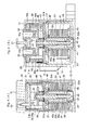
- a sealed electromagnetic relay contains, inside a housing formed by assembling a cover 20 to a case 10, a contact mechanical portion 30 incorporated in a sealed space 43 made by a ceramic plate 31, a metal cylindrical flange 32, a plate-like first yoke 37 and a bottomed cylindrical body 41, and an electromagnet portion 50 that drives this contact mechanical portion 30 from an outside of the sealed space 43.
- the case 10 is a substantially box-shaped resin molded article, in which attachment holes 11 are provided in lower corner portions of outer side surfaces, while a bulging portion 12 to lead out a lead wire not shown is formed in a side-surface corner portion, and locking holes 13 are provided in opening edge portions in opposed side surfaces.
- the cover 20 has a shape that can cover an opening portion of the case 10, and terminal holes 22, 22 are respectively provided on both sides of a partition wall 21 projected in an upper-surface center thereof. Moreover, in the cover 20, there is provided, in one side surface, a projected portion 23 that is inserted into the bulging portion 12 of the case 10 to be able to prevent so-called fluttering of the lead wire not shown. Furthermore, in the cover 20, locking claw portions 24 that can be locked in the locking holes 13 of the case 10 are provided in opening edge portions of opposed side surfaces.
- the contact mechanical portion 30 is arranged inside the sealed space 43 formed by the ceramic plate 31, the metal cylindrical flange 32, the plate-like first yoke 37 and the bottomed cylindrical body 41, and is made up of a magnet holder 35, a fixed iron core 38, a movable iron core 42, a movable shaft 45 and a movable contact piece 48.
- the ceramic plate 31 has a shape that can be brazed to an upper opening edge portion of the metal cylindrical flange 32 described later, and is provided with a pair of terminal holes 31 a and 31 a and a vent hole 31 b (refer to Figs. 4A , 5A).
- a metal layer not shown is formed in an outer circumferential edge portion of an upper surface thereof, opening edge portions of the terminal holes 31a, and an opening edge portion of the vent hole 31 b, respectively.
- fixed contact terminals 33 to which fixed contacts 33a adhere at lower end portions thereof are brazed to the terminal holes 31 a of the ceramic plate 31, and a vent pipe 34 is brazed to the vent hole 31 b.
- the metal cylindrical flange 32 brazed to an upper-surface circumferential edge portion of the ceramic plate 31 has a substantially cylindrical shape formed by subjecting a metal plate to press working.
- a lower outer circumferential portion thereof is welded to, and integrated with the plate-like first yoke 37 described later.
- the magnet holder 35 contained in the metal cylindrical flange 32 is made of a thermally-resistant insulating material having a box shape, as shown in Figs. 3 , and is formed with pocket portions 35a capable of holding permanent magnets 36 on opposed both outer side surfaces, respectively.
- an annular cradle 35c is provided in a bottom-surface center thereof so as to be one-step lower, and a cylindrical insulating portion 35b is projected downward from a center of the annular cradle 35c.
- the plate-like first yoke 37 has a shape that can be fitted in an opening edge portion of the case 10, and an annular step portion 37a is formed in an upper surface thereof by protrusion process, and a caulking hole 37b is provided in a center thereof.
- an upper end portion of the cylindrical fixed iron core 38 is fixed to the caulking hole 37b by caulking, while a lower opening portion of the metal cylindrical flange 32 is fitted on the annular step portion 37a to be welded and integrated from outside.
- the metal cylindrical flange 32 is fitted on the annular step portion 37a from above, which enables both to be positioned precisely and easily. Moreover, the lower opening edge portion of the metal cylindrical flange 32 is welded and integrated with the annular step portion 37a of the plate-like first yoke 37 from outside. Therefore, the present embodiment has an advantage that wide lateral welding margins are not required, thereby resulting in the contact switching device with a small floor area.
- the movable shaft 45 with an annular flange portion 45a is inserted into a through-hole 38a so as to move slidably through the cylindrical insulating portion 35b of the magnet holder 35.
- a return spring 39 is put on the movable shaft 45, and the movable iron core 42 is fixed to a lower end portion of the movable shaft 45 by welding.
- an opening edge portion thereof is airtightly bonded to a lower-surface edge portion of the caulking hole 37b provided in the plate-like first yoke 37. After internal air is suctioned from the vent pipe 34, gas is charged and sealing is performed, by which the sealed space 43 is formed.
- a disk-like receiver 46 is locked by the annular flange portion 45a provided at an intermediate portion of the movable shaft 45 to thereby prevent a contact spring 47 and the movable contact piece 48, which have been put on the movable shaft 45, from coming off, and a retaining ring 49 is fixed to an upper end portion.
- Movable contacts 48a provided in upper-surface both end portions of the movable contact piece 48 are opposed to the fixed contacts 33a of the contact terminals 33 arranged inside the metal cylindrical flange 32 so as to be able to contact and depart from the fixed contacts 33a.
- coil terminals 53 and 54 are pressed into, and fixed to a flange portion 52a of a spool 52 which the coil 51 is wound around, and the coil 51 and lead wires not shown are connected through the coil terminals 53 and 54.
- the bottomed cylindrical body 41 is inserted into a through-hole 52b of the spool 52, and is fitted in a fitting hole 56a of a second yoke 56.
- both side portions 57 and 57 of the second yoke 56 are engaged with both end portions of the plate-like first yoke 37, and are fixed by means of caulking, press-fitting, welding or the like, by which the electromagnet portion 50 and the contact mechanical portion 30 are integrated.
- the present embodiment even when the movable shaft 45 returns to the original state, the movable iron core 42 does not abut on the bottom surface of the bottomed cylindrical body 41. Therefore, the present embodiment has an advantage that impact sound is absorbed and alleviated by the magnet holder 35, the fixed iron core 38, the electromagnet portion 50 and the like, thereby resulting in the sealed electromagnetic relay having small switching sound.
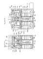
- a sealed electromagnetic relay contains, inside a housing formed by assembling a cover 120 to a case 110, a contact mechanical portion 130 incorporated in a sealed space 143 made by a metal frame body 160, a ceramic plate 131, a metal cylindrical flange 132, a plate-like first yoke 137 and a bottomed cylindrical body 141, and an electromagnet portion 150 that drives the contact mechanical portion 130 from an outside of the sealed space 143.
- the case 110 is a substantially box-shaped resin molded article, in which attachment holes 111 are provided in lower corner portions of outer side surfaces, while a bulging portion 112 to lead out a lead wire not shown is formed in a side-surface corner portion, and locking holes 113 are provided in opening edge portions in opposed side surfaces.
- attachment holes 111 cylindrical clasps 114 are insert-molded.
- the cover 120 has a shape that can cover an opening portion of the case 110, and terminal holes 122, 122 are respectively provided on both sides of a partition wall 121 projected in an upper-surface center thereof. Moreover, in the cover 120, there is provided, in one side surface, a projected portion 123 that is inserted into the bulging portion 112 of the case 110 to be able to prevent so-called fluttering of the lead wire not shown. Furthermore, in the cover 120, locking claw portions 124 that can be locked in the locking holes 113 of the case 110 are provided in opening edge portions of opposed side surfaces.
- the contact mechanical portion 130 is arranged inside the sealed space 143 formed by the metal frame body 160, the ceramic plate 131, the metal cylindrical flange 132, the plate-like first yoke 137 and the bottomed cylindrical body 141.
- the contact mechanical portion 130 is made up of a magnet holder 135, a fixed iron core 138, a movable iron core 142, a movable shaft 145, a movable contact piece 148, and a lid body 161.
- the metal frame body 160 has a shape that can be brazed to an upper-surface outer circumferential edge portion of the ceramic plate 131 described later.
- the metal frame body 160 has a ring portion 160a to support a vent pipe 134 described later in an inner edge portion thereof, and an outer circumferential rib 160b to be welded to an opening edge portion of the metal cylindrical flange 132 described later in an outer circumferential edge portion thereof.
- the ceramic plate 131 has a shape that allows the upper-surface outer circumferential edge portion of the ceramic plate 131 to be brazed to an opening edge portion of the metal frame body 160, and is provided with a pair of terminal holes 131 a, 131 a and a vent hole 131 b.
- a metal layer not shown is formed in the upper-surface outer circumferential edge portion thereof, opening edge portions of the terminal holes 131a, and an opening edge portion of the vent hole 131 b, respectively.
- a rectangular frame-shaped brazing material 172 including a ring portion 172a corresponding to the opening edge portion of the vent hole 131 b is arranged. Furthermore, the ring portion 160a of the metal frame body 160 is overlaid on the ring portion 172a of the rectangular frame-shaped brazing material 172 to perform positioning.
- the vent pipe 134 is inserted into the ring portion 160a of the metal frame body 160 and the vent hole 131 b of the ceramic plate 131.
- the fixed contact terminals 133 on which ring-shaped brazing materials 170, rings for terminals 133b, and ring-shaped brazing materials 171 are sequentially put are inserted into the terminal holes 131 a of the ceramic plate 131. Subsequently, the foregoing brazing materials 170, 171, and 172 are heated and melted to perform the brazing.
- the fixed contact terminals 133 inserted into the terminal holes 131 a of the ceramic plate 131 through the rings for terminal 133b have the fixed contacts 133a adhered thereto at lower end portions.
- the rings for terminal 133b are to absorb and adjust a difference in a coefficient of thermal expansion between the ceramic plate 131 and the fixed contact terminals 133.
- the vent pipe 134 inserted into the terminal hole 131 a of the ceramic plate 131 is brazed through the ring portion 160a of the metal frame body 160 and the ring 172a of the rectangular frame-shaped brazing member 172. This enhances sealing properties, thereby resulting in the contact switching device having a sealed structure excellent in mechanical strength, particularly in impact resistance.
- the metal cylindrical flange 132 has a substantially cylindrical shape formed by subjecting a metal plate to press working.
- an outer circumferential rib 132a provided in an upper opening portion of the metal cylindrical flange portion is welded to, and integrated with the outer circumferential rib 160b of the metal frame body 160, and an opening edge portion on a lower side thereof is welded to, and integrated with the plate-like first yoke 137 described later.
- the structure may be such that the metal frame body 160 and the metal cylindrical flange 132 are integrally molded by press working in advance, and an outer circumferential rib provided in a lower opening portion of the metal cylindrical flange portion 132 may be welded to, and integrated with an upper surface of the plate-like first yoke 137.
- the present constitution not only the foregoing outer circumferential rib 160b of the metal frame body 160 and the outer circumferential rib 132a of the metal cylindrical flange 132 can be omitted, but welding processes of them can be omitted.
- the metal cylindrical flange 132 and the plate-like first yoke 137 can be welded vertically, the welding process can be simplified as compared with a method of welding from outside, which brings about the contact switching device high in productivity.
- the plate-like first yoke 137 has a shape that can be fitted in an opening edge portion of the case 110.
- positioning projections 137a are provided with a predetermined pitch on an upper surface thereof, and a fitting hole 137b is provided in a center thereof.
- an inner V-shaped groove 137c is annularly provided so as to connect the positioning projections 137a, and an outer V-shaped groove 137d surrounds the inner V-shaped groove 137c.
- a rectangular frame-shaped brazing material 173 is positioned, and the opening edge portion on the lower side of the metal cylindrical flange 132 is positioned by the positioning projections 137a.
- the rectangular frame-shaped brazing material 173 is melted to braze the lower opening edge portion of the metal cylindrical flange 132 to the plate-like first yoke 137 (Fig. 21 B).
- an upper end portion of the cylindrical fixed iron core 138 is brazed to the fitting hole 137b by a brazing material 174.
- the metal cylindrical flange 132 is assembled to the positioning projections 137a from above to abut on the same, which enables precise and easy positioning. Moreover, when the opening edge portion on the lower side of the metal cylindrical flange 132 is integrated with the upper surface of the plate-like first yoke 137 by brazing, even if the melted brazing material flows out, the melted brazing material is retained in the inner V-shaped groove 137c and the outer V-shaped groove 137d. This prevents the melted brazing material from deeply flowing into the metal cylindrical flange 132, and from flowing outside the plate-like first yoke 137. As a result, since proficiency is not required for the brazing work, and the work is easy, which leads to an advantage of increase in productivity.
- the magnet holder 135 has a box shape that can be contained inside the metal cylindrical flange 132, and is formed of a thermally-resistant insulating material. Moreover, as shown in Figs. 13 and 14 , the magnet holder 135 is formed with pocket portions 135a capable of holding permanent magnets 136 on opposed both outer side surfaces, respectively. Furthermore, in the magnet holder 135, an annular cradle 135c is provided in a bottom-surface center thereof so as to be one-step lower, and a cylindrical insulating portion 135b having a through-hole 135f is projected downward from a center of the annular cradle 135c.
- the cylindrical insulating portion 135b even if arc is generated, and a high voltage is caused in a channel of the metal cylindrical flange 132, the plate-like first yoke 137 and the cylindrical fixed iron core 138, insulating the cylindrical fixed iron core 138 and the movable shaft 145 from each other prevents both from melting and adhering to, and being integrated with each other.
- depressed portions 135d to press position restricting plates 162 described later into are provided in opposed inner surfaces.
- a pair of depressions 135e in which buffer materials 163 described later can be fitted is provided on a bottom-surface back side thereof.
- the position restricting plates 162 are each made of a substantially rectangular elastic metal plate in a front view, and both side edge portions thereof are cut and raised to form elastic claw portions 162a.
- the position restricting plates 162 are pressed into the depressed portions 135d of the magnet holder 135 to restrict idle rotation of the movable contact piece 148 described later.
- the buffer materials 163 are each made of an elastic material, which has a block shape that in a plan view has an appearance which looks substantially like the number 8, and are pressed into the depressions 135e of the magnet holder 135 and sandwiched between the magnet holder 135 and the plate-like first yoke 137 ( Figs. 24A and 25A ).
- Forming the buffer materials 163 into the number 8-shape in a plan view is to obtain desired elasticity in an unbiased manner while assuring a wide floor area and assuring a stable supporting force. Moreover, according to the present embodiment, not only selection of the materials but also change of the shape enables the elasticity to be adjusted, thereby making silence design easy. Furthermore, the buffer materials 163 are not limited to the foregoing shape, but for example, a lattice shape or an O shape may be employed.
- the buffer materials are not limited to the foregoing block shape, but may have a sheet shape. Moreover, the block-shaped buffer materials and the sheet-like buffer materials may be stacked, and be sandwiched between the bottom-surface back side of the magnet holder 135 and the plate-like first yoke 137.
- the buffer materials are not limited to a rubber material or a resin material, but a metal material such as copper alloy, SUS, aluminum and the like may be employed.
- the movable shaft 145 with an annular flange portion 145a is inserted into a through-hole 138a so as to move slidably through the cylindrical insulating portion 135b of the magnet holder 135.
- a return spring 139 is put on the movable shaft 145, and the movable iron core 142 is fixed to a lower end portion of the movable shaft 145 by welding.
- the movable iron core 142 has an annular attracting and sticking portion 142b in an upper opening edge portion of a cylindrical outer circumferential portion 142a, and a cylindrical inner circumferential portion 142c is projected inward from an opening edge portion of the annular attracting and sticking portion 142b.
- the cylindrical inner circumferential portion 142c is put on, and integrated with the lower end portion of the movable shaft 145.
- an opening edge portion thereof is airtightly bonded to a lower surface edge portion of the caulking hole 137b provided in the plate-like first yoke 137. After internal air is suctioned from the vent pipe 134, gas is charged and sealing is performed, by which the sealed space 143 is formed.
- the movable shaft 145 is provided with the annular flange portion 145a at an intermediate portion thereof.
- movable contacts 148a provided in an upper-surface both end portions of the movable contact piece 148 are opposed to the fixed contacts 133a of the contact terminals 133 arranged inside the metal cylindrical flange 132 so as to be able to contact and depart from the fixed contacts 133a.
- the movable contact piece 148 has, in a center thereof, a shaft hole 148b into which the movable shaft 145 can be inserted, and four projections for position restriction 148c are provided in an outer circumferential surface thereof.
- a disk-like receiver 146 is put on the movable shaft 145, and subsequently, a small contact spring 147a, a large contact spring 147b and the movable contact piece 148 are put on the movable shaft 145. Furthermore, a retaining ring 149 is fixed to an upper end portion of the movable shaft 145 to thereby retain the movable contact piece 148 and the like.
- the lid body 161 has an H shape in a plan view that can be fitted in an opening portion of the magnet holder 135.
- tongue pieces for position restriction 161 a are projected in lower-surface both-side edge portions.
- the lid body 161 restricts floating of the position restricting plates 162 incorporated in the magnet holder 135 by the tongue pieces for position restriction 161 a thereof.
- four extending portions 161 b extending laterally from corner portions of the lid body 161 close the opening portion having a complicated shape of the magnet holder 135.
- the extending portions 161 b prevent the metal frame body 160 and the fixed contacts 133a from being short-circuited by flow-out from the opening portion of the magnet holder 135 to the outside and deposition of scattered objects caused by arc generated at the time of contact switching.
- a plurality of capture grooves 161 c are provided side by side so as to bridge between the tongue pieces for position restriction 161 a, 161 a on a back surface of the lid body 161.
- the capture grooves 161 c efficiently retain the scattered objects generated by the arc, by which the short-circuit between the fixed contacts 133a, 133a can be prevented, thereby increasing insulation properties.
- a view when a horizontal cross section of the contact switching device according to the present embodiment to which the position restricting plates 162 are assembled is seen from underneath is as shown in Fig. 27 .
- the generated arc is extended vertically along a paper plane of Fig. 27 , based on Fleming's left-hand rule. This allows the scattered objects to be shielded by the extending portions 161 b of the lid body 161, even if the scattered objects are caused by the arc.
- the scattered objects do not flow outside from an interfacial surface between an opening edge portion of the magnet holder 135 and a lower surface of the ceramic plate 131, so that the metal cylindrical flange 132 and the fixed contacts 133a are not short-circuited, which brings about an advantage that high insulation properties can be assured.
- the lid body 161 is not limited to the foregoing shape, but for example, as illustrated in Figs. 23 , a rectangular shape that can be fitted in the opening portion of the magnet holder 135 may be employed.
- the tongue pieces for position restriction 161 a, 161 a are respectively projected in opposed edge portions on both sides on the back surface, and the plurality of capture grooves 161 c are provided side by side to efficiently retain the scattered objects between the tongue pieces for position restriction 161 a, 161 a.
- a pair of contact holes 161d is provided with the capture grooves 161 c interposed, and a plurality of capture grooves 161e are provided side by side on both sides of the contact holes 161 d.
- coil terminals 153 and 154 are pressed into, and fixed to a flange portion 152a of a spool 152 around which a coil 151 is wound.
- the coil 151 and lead wires not shown are connected through the coil terminals 153 and 154.
- slits for press-fitting 152c are provided at corner portions of the flange portion 152a thereof, and guide grooves 152d and locking holes 152e are provided so as to communicate with the slits for press-fitting 152c.
- a coil entwining portion 153a extends in an opposite direction of a press-fitting direction of a press-fitting portion 153h, while a lead wire connecting portion 153b extends in a direction perpendicular to the press-fitting direction of the press-fitting portion 153h. This makes the coil entwining portion 153a and the lead wire connecting portion 153b orthogonal to each other.
- a projection for guide 153c is formed in the press-fitting portion 153h by a protrusion process, and a locking claw 153d is cut and raised.
- a cutter surface 15g utilizing a warp generated at the time of press working is formed at a free end portion thereof.
- a hole for inserting the lead wire 153e and a cut-out portion for entwining 153f are provided adjacently to each other at the free end portion.
- the projections for guide 153c and 154c of the coil terminals 153 and 154 are engaged with the guide grooves 152d of the spool 152 illustrated in Fig. 20A , and temporarily joined.
- the press-fitting portions 153h and 154h of the coil terminals 153 and 154 are pressed into the slits for press-fitting 152c, and the locking claws 153d and 154d are locked in the locking holes 152e and 152e to be retained.
- lead-out lines of the coil 151 are entwined around the coil entwining portions 153a, and 154a of the coil terminals 153 and 154, and are cut by the cutter surfaces 153g and 154g to be soldered.
- terminal ends of the lead wires not shown are inserted into the through-holes 153e and 154e of the coil terminals 153 and 154, they are entwined around the cut-out portions 153f and 154f and soldered, which allows the coil 151 and the lead wires not shown to be connected.
- the bottomed cylindrical body 141 is inserted into a through-hole 152b of the spool 152, and is inserted into a fitting hole 156a of a second yoke 156 to be fitted on a fixed flange 158. Subsequently, upper-end corner portions of both side portions 157, 157 of the second yoke 156 are engaged with corner portions of the plate-like first yoke 137 to be fixed by means of caulking, press-fitting, welding or the like, by which the electromagnet portion 150 and the contact mechanical portion 130 are integrated.
- the substantially 8-shaped buffer materials 163 fitted in the depressions 135e of the magnetic holder 135 are sandwiched between the plate-like first yoke 137 and the magnet holder 135 ( Figs. 24A and 25A ).
- the coil entwining portion 153a and the lead wire connecting portion 153b are provided separately, the coil 151 does not disturb the connection work of the lead wire, which increases workability. Moreover, the use of the through-hole 153e and the cut-out portion 153f provided in the lead wire connecting portion 153b makes the connection easier, and makes coming-off of the lead wire more difficult. Furthermore, when the coil entwining portion 153a and the lead wire connecting portion 153b are bent and raised at a right angle, both stand at adjacent corner portions of the flange portion 152a, respectively.
- the coil terminal 154 having the mirror-symmetrical shape to the coil terminal 153 has an advantage similar to that of the coil terminal 153.
- the three coil terminals may be arranged at the three corner portions of the flange portion 152a of the spool 152 as needed.
- an impact force of the movable shaft 145 is absorbed and alleviated by the buffer materials 163 through the magnet holder 135.
- the movable iron core 142 does not abut on the bottom surface of the bottomed cylindrical body 141. Therefore, the present embodiment has an advantage that hitting sound of the movable shaft 45 is absorbed and alleviated by the magnet holder 135, the buffer materials 163, the fixed iron core 138, the electromagnet portion 150 and the like, thereby bringing about the sealed electromagnetic relay having small switching sound.
- the position restricting plates 162 of the present embodiment as illustrated in Figs. 26 , vertical movement of the movable shaft 145 allows the movable contact piece 148 to vertically move. At this time, even if shaking occurs in the movable contact piece 148, the projections for position restriction 148c of the movable contact piece 148 abut on the position restricting plates 162 pressed into the depressed portions 135d of the magnet holder 135, so that the position of the movable contact piece 148 is restricted. Thus, the movable contact piece 148 does not directly come into contact with the magnet holder 135 made of resin, which prevents resin powder from being produced, so that a contact failure does not occur. Particularly, since the position restricting plates 162 are formed of the same metal material as the movable contact piece 148, abrasion powder is hardly produced.
- the spring load can be adjusted in two steps, the spring load can be adjusted so as to be in line with the attraction force of the electromagnet portion 150.
- the larger contact force and the larger contact follow can be assured, and the contact switching device favorable in operation characteristics can be obtained.
- the small contact spring 147a is arranged inside the large contact spring 147b. Therefore, at the operating time, the large contact spring 147b having a large length dimension and a small spring contact is first pressed (between P1 and P2 in the contact follow in Fig. 37A ). Thereafter, the small contact spring 147a having a small length dimension and a large spring constant is pressed (on the left side of P2 in the contact follow in Fig. 37A ). As a result, it becomes easy for the spring load to be in line with the attraction force of the electromagnet portion, which rapidly increases at an end stage of the operation, so that the desired contact force can be obtained and the contact switching device having a small height dimension can be obtained.
- the large contact spring 147b and the small contact spring 147a Since as the large contact spring 147b and the small contact spring 147a, coil springs are used, they do not spread radially, and a radial dimension can be made small. Furthermore, there is an advantage that since the small contact spring 147a is put on the movable shaft 145, backlash hardly occurs, so that the electromagnetic relay without fluctuations in operation characteristics can be obtained.
- the arrangement may be such that the length dimension of the small contact spring 147a is larger than that of the large contact spring 147b, the spring constant is smaller than that of the large contact spring 147b, so that the small contact spring 147a is first pressed.
- the constitution may be such that the small contact spring 147a and the large contact spring 147b are joined at one-end portions to continue to each other. In these cases, the desired contact force can be obtained.
- an annular partition wall 135g is provided so as to surround the through-hole 135f provided in a bottom-surface center of the magnet holder 135.
- an opening edge portion of the annular partition wall 135g approaches a lower surface vicinity of the movable contact piece 148. Therefore, there is an advantage that the scattered objects generated by the arc or the like hardly enter the through-hole 135f of the magnet holder 135, thus hardly causing an operation failure. Since other constitutions are similar to those of the foregoing embodiments, the same portions are given the same numbers, and descriptions thereof are omitted.
- annular partition wall 148d is projected in a lower surface center of the movable contact piece 148. Therefore, the annular partition wall 148d of the movable contact piece 148 is fitted on the annular partition wall 135g provided in the magnet holder 135 from outside, which can make a creepage distance of both longer. According to the present embodiment, there is an advantage that the creepage distance from an outer circumferential edge portion of the movable contact piece 148 to the through-hole 135f of the magnet holder 135 becomes still longer, which makes it hard for dust and the like to enter the through-hole 135f, thereby increasing durability.
- annular partition wall 135g is provided in the bottom-surface center of the magnet holder 135
- the invention is not limited thereto.
- a pair of partition walls may extend parallel so as to bridge opposed inner side surfaces of the magnet holder 135, and the through-hole 135f may be finally partitioned by the rectangular frame-shaped partition wall 135g.
- annular partition wall 135g projected in the bottom-surface center of the magnet holder 135 may be fitted in an annular groove 148e provided in a lower surface of the movable contact piece 148 to prevent dust from coming in.
- annular flange portion 135h may be extended outward from the upper end edge portion of the annular partition wall 135g provided in the magnet holder 135.
- the lower surface of the movable contact piece 148 and the annular flange portion 135h are vertically opposed to each other with a gap formed, which prevents the scattered objects from coming in.
- Figs. 38 by applying spot facing working to the movable iron core 142, relationships between the weight saving and the silencing were measured. That is, as shown in Figs. 38A, 38B, and 38C , the spot facing working was applied to the movable iron core 142 to save the weight, and the operating sound was measured. As a result, as shown in Figs. 38D and 38E , it could be confirmed that as the spot facing was deeper, the weight of the movable iron core was saved more, so that the operating sound was reduced.
- the inner circumferential portion 142c of the movable iron core 142 is to surely support the lower end portion of the movable shaft 145, but is not necessarily required and only needs to have a minimum necessary size.
- the contact switching device according to the present invention is not limited to the foregoing electromagnetic relay but the present invention may be applied to another contact switching device.
Landscapes
- Physics & Mathematics (AREA)
- Electromagnetism (AREA)
- Contacts (AREA)
- Electromagnets (AREA)
Applications Claiming Priority (3)
| Application Number | Priority Date | Filing Date | Title |
|---|---|---|---|
| JP2010058009 | 2010-03-15 | ||
| JP2010058010 | 2010-03-15 | ||
| PCT/JP2011/055929 WO2011115050A1 (ja) | 2010-03-15 | 2011-03-14 | 接点開閉装置 |
Publications (2)
| Publication Number | Publication Date |
|---|---|
| EP2549498A1 true EP2549498A1 (de) | 2013-01-23 |
| EP2549498A4 EP2549498A4 (de) | 2014-08-13 |
Family
ID=44649142
Family Applications (9)
| Application Number | Title | Priority Date | Filing Date |
|---|---|---|---|
| EP11756241.3A Active EP2549510B1 (de) | 2010-03-15 | 2011-03-14 | Kontaktschaltvorrichtung |
| EP11756238.9A Active EP2549508B1 (de) | 2010-03-15 | 2011-03-14 | Kontaktschaltvorrichtung |
| EP11756239.7A Active EP2549509B1 (de) | 2010-03-15 | 2011-03-14 | Spulenklemme |
| EP11756234.8A Active EP2549507B1 (de) | 2010-03-15 | 2011-03-14 | Kontaktschaltvorrichtung |
| EP11756242.1A Active EP2549506B1 (de) | 2010-03-15 | 2011-03-14 | Kontaktschaltvorrichtung |
| EP11756235.5A Withdrawn EP2549498A4 (de) | 2010-03-15 | 2011-03-14 | Kontaktschaltvorrichtung |
| EP11756240.5A Active EP2549513B1 (de) | 2010-03-15 | 2011-03-14 | Kontaktschaltvorrichtung |
| EP11756237.1A Active EP2549512B1 (de) | 2010-03-15 | 2011-03-14 | Kontaktschaltvorrichtung |
| EP11756244.7A Active EP2549511B1 (de) | 2010-03-15 | 2011-03-14 | Kontaktschaltvorrichtung |
Family Applications Before (5)
| Application Number | Title | Priority Date | Filing Date |
|---|---|---|---|
| EP11756241.3A Active EP2549510B1 (de) | 2010-03-15 | 2011-03-14 | Kontaktschaltvorrichtung |
| EP11756238.9A Active EP2549508B1 (de) | 2010-03-15 | 2011-03-14 | Kontaktschaltvorrichtung |
| EP11756239.7A Active EP2549509B1 (de) | 2010-03-15 | 2011-03-14 | Spulenklemme |
| EP11756234.8A Active EP2549507B1 (de) | 2010-03-15 | 2011-03-14 | Kontaktschaltvorrichtung |
| EP11756242.1A Active EP2549506B1 (de) | 2010-03-15 | 2011-03-14 | Kontaktschaltvorrichtung |
Family Applications After (3)
| Application Number | Title | Priority Date | Filing Date |
|---|---|---|---|
| EP11756240.5A Active EP2549513B1 (de) | 2010-03-15 | 2011-03-14 | Kontaktschaltvorrichtung |
| EP11756237.1A Active EP2549512B1 (de) | 2010-03-15 | 2011-03-14 | Kontaktschaltvorrichtung |
| EP11756244.7A Active EP2549511B1 (de) | 2010-03-15 | 2011-03-14 | Kontaktschaltvorrichtung |
Country Status (6)
| Country | Link |
|---|---|
| US (9) | US9058938B2 (de) |
| EP (9) | EP2549510B1 (de) |
| JP (9) | JP5360291B2 (de) |
| KR (9) | KR101387386B1 (de) |
| CN (9) | CN102804318B (de) |
| WO (9) | WO2011115057A1 (de) |
Cited By (7)
| Publication number | Priority date | Publication date | Assignee | Title |
|---|---|---|---|---|
| EP2648204A1 (de) * | 2010-12-02 | 2013-10-09 | Fuji Electric Co., Ltd. | Elektromagnetisches schütz, gasdichtungsverfahren für das elektromagnetische schütz und verfahren zur herstellung des elektromagnetischen schützes |
| FR3026222A1 (fr) * | 2014-09-24 | 2016-03-25 | Schneider Electric Ind Sas | Actionneur electromagnetique et contacteur electrique comprenant un tel actionneur |
| US9728360B2 (en) | 2015-04-22 | 2017-08-08 | Ellenberger & Poensgen Gmbh | Power relay for a vehicle |
| EP3306637A1 (de) * | 2016-10-04 | 2018-04-11 | Delta Electronics, Inc. | Kontaktmechanismus eines elektromagnetischen relais |
| WO2019201806A1 (de) * | 2018-04-19 | 2019-10-24 | Tdk Electronics Ag | Schaltvorrichtung |
| WO2019215047A1 (de) * | 2018-05-07 | 2019-11-14 | Tdk Electronics Ag | Schaltvorrichtung |
| WO2024125798A1 (de) * | 2022-12-15 | 2024-06-20 | Pierburg Gmbh | Hochvoltschütz oder hochvoltrelais mit einem einstückigen aktorgehäuseteil aus kunstoff |
Families Citing this family (116)
| Publication number | Priority date | Publication date | Assignee | Title |
|---|---|---|---|---|
| JP2012507090A (ja) | 2008-10-27 | 2012-03-22 | ミューラー インターナショナル エルエルシー | インフラ監視システムおよび方法 |
| CA2772545C (en) | 2009-05-22 | 2018-12-11 | Mueller International, Inc. | Infrastructure monitoring devices, systems, and methods |
| JP5360291B2 (ja) | 2010-03-15 | 2013-12-04 | オムロン株式会社 | 接点開閉装置 |
| CA3060512C (en) | 2010-06-16 | 2021-06-08 | Mueller International, Llc | Infrastructure monitoring devices, systems, and methods |
| KR101406357B1 (ko) * | 2010-07-16 | 2014-06-12 | 파나소닉 주식회사 | 접점 장치 |
| KR101086907B1 (ko) * | 2010-10-15 | 2011-11-25 | 엘에스산전 주식회사 | 계전기 |
| JP5689741B2 (ja) * | 2011-05-19 | 2015-03-25 | 富士電機株式会社 | 電磁接触器 |
| CN103748652B (zh) * | 2011-05-31 | 2016-06-01 | 欧姆龙株式会社 | 电磁继电器 |
| US8833390B2 (en) | 2011-05-31 | 2014-09-16 | Mueller International, Llc | Valve meter assembly and method |
| US8855569B2 (en) | 2011-10-27 | 2014-10-07 | Mueller International, Llc | Systems and methods for dynamic squelching in radio frequency devices |
| KR101216824B1 (ko) * | 2011-12-30 | 2012-12-28 | 엘에스산전 주식회사 | 직류 릴레이 |
| JP6193566B2 (ja) * | 2012-01-25 | 2017-09-06 | 日本特殊陶業株式会社 | 継電器 |
| JP5914065B2 (ja) * | 2012-03-12 | 2016-05-11 | 富士電機機器制御株式会社 | 開閉器 |
| JP5966469B2 (ja) * | 2012-03-15 | 2016-08-10 | オムロン株式会社 | 封止接点装置 |
| JP5965197B2 (ja) | 2012-04-13 | 2016-08-03 | 富士電機機器制御株式会社 | 開閉器 |
| DE112012005870T5 (de) * | 2012-05-17 | 2014-10-30 | Mitsubishi Electric Corporation | Elektromagnetischer Schalter |
| CN103426684B (zh) * | 2012-05-21 | 2017-02-08 | 博世汽车部件(长沙)有限公司 | 电磁开关、其制造方法及车辆起动机 |
| JP5938745B2 (ja) | 2012-07-06 | 2016-06-22 | パナソニックIpマネジメント株式会社 | 接点装置および当該接点装置を搭載した電磁継電器 |
| CN103578806A (zh) * | 2012-07-20 | 2014-02-12 | 太仓子午电气有限公司 | 一种方便安装磁性开关 |
| EP2889892B1 (de) * | 2012-08-23 | 2017-02-01 | Panasonic Intellectual Property Management Co., Ltd. | Kontaktvorrichtung |
| KR20140033814A (ko) * | 2012-09-10 | 2014-03-19 | 엘에스산전 주식회사 | 전자개폐장치 |
| JP6138451B2 (ja) * | 2012-10-24 | 2017-05-31 | 日本特殊陶業株式会社 | 継電器 |
| JP6064223B2 (ja) * | 2012-12-28 | 2017-01-25 | パナソニックIpマネジメント株式会社 | 接点装置および当該接点装置を搭載した電磁継電器 |
| KR101422394B1 (ko) | 2013-02-18 | 2014-07-22 | 엘에스산전 주식회사 | 전자 개폐 장치 |
| US10046303B2 (en) | 2013-04-26 | 2018-08-14 | Corning Incorporated | Disassemblable stacked flow reactor |
| JP2014232669A (ja) * | 2013-05-29 | 2014-12-11 | パナソニック株式会社 | 接点装置 |
| JP6136597B2 (ja) | 2013-06-06 | 2017-05-31 | 株式会社明電舎 | 封止形リレー |
| JP6136598B2 (ja) * | 2013-06-06 | 2017-05-31 | 株式会社明電舎 | 封止形リレー |
| CN103367038A (zh) * | 2013-06-21 | 2013-10-23 | 无锡康伟工程陶瓷有限公司 | 固态继电器瓷接件 |
| JP6358442B2 (ja) * | 2013-06-28 | 2018-07-18 | パナソニックIpマネジメント株式会社 | 接点装置および当該接点装置を搭載した電磁継電器 |
| JP6202943B2 (ja) * | 2013-08-26 | 2017-09-27 | 富士通コンポーネント株式会社 | 電磁継電器 |
| JP5741740B1 (ja) | 2014-03-14 | 2015-07-01 | オムロン株式会社 | 封止接点装置およびその製造方法 |
| DE102014004455B4 (de) * | 2014-03-27 | 2021-10-07 | Schaltbau Gmbh | Elektrische Schaltvorrichtung mit verbesserter Lichtbogenlöscheinrichtung und Verfahren zur Herstellung derartiger Schaltvorrichtung |
| US9494249B2 (en) | 2014-05-09 | 2016-11-15 | Mueller International, Llc | Mechanical stop for actuator and orifice |
| CN103956298B (zh) * | 2014-05-12 | 2017-01-11 | 中国航天时代电子公司 | 大功率电磁继电器柔性阻绝结构 |
| JP2015220186A (ja) * | 2014-05-20 | 2015-12-07 | 富士電機機器制御株式会社 | 電磁接触器及びこれを使用したコンビネーションスタータ |
| US10269517B2 (en) | 2014-06-19 | 2019-04-23 | Panasonic Intellectual Property Management Co., Ltd. | Contact device, electromagnetic relay using the same, and method for manufacturing contact device |
| CN104078250B (zh) * | 2014-06-27 | 2017-11-28 | 厦门宏发开关设备有限公司 | 一种线圈端子导电片结构 |
| JP6433706B2 (ja) * | 2014-07-28 | 2018-12-05 | 富士通コンポーネント株式会社 | 電磁継電器及びコイル端子 |
| CN104091706B (zh) * | 2014-07-29 | 2016-08-10 | 厦门宏发电力电器有限公司 | 一种继电器及其电弧防护结构 |
| CN104134570A (zh) * | 2014-08-12 | 2014-11-05 | 无锡康伟工程陶瓷有限公司 | 真空继电器瓷片 |
| US9565620B2 (en) | 2014-09-02 | 2017-02-07 | Mueller International, Llc | Dynamic routing in a mesh network |
| KR200486468Y1 (ko) * | 2014-09-29 | 2018-07-05 | 엘에스산전 주식회사 | 직류 릴레이 |
| DE102014116139A1 (de) * | 2014-11-05 | 2016-05-12 | Epcos Ag | Induktives Bauelement |
| JP6414453B2 (ja) * | 2014-12-05 | 2018-10-31 | オムロン株式会社 | 電磁継電器 |
| CN107077996B (zh) * | 2014-12-05 | 2019-03-29 | 欧姆龙株式会社 | 电磁继电器 |
| JP2016110843A (ja) * | 2014-12-05 | 2016-06-20 | オムロン株式会社 | 電磁継電器 |
| US9552951B2 (en) * | 2015-03-06 | 2017-01-24 | Cooper Technologies Company | High voltage compact fusible disconnect switch device with magnetic arc deflection assembly |
| KR101943363B1 (ko) * | 2015-04-13 | 2019-04-17 | 엘에스산전 주식회사 | 전자개폐기 |
| JP6590273B2 (ja) * | 2015-04-13 | 2019-10-16 | パナソニックIpマネジメント株式会社 | 接点装置および電磁継電器 |
| JP6528271B2 (ja) * | 2015-04-13 | 2019-06-12 | パナソニックIpマネジメント株式会社 | 接点装置および電磁継電器 |
| KR101943364B1 (ko) * | 2015-04-23 | 2019-04-17 | 엘에스산전 주식회사 | 전자개폐기 |
| US9865419B2 (en) * | 2015-06-12 | 2018-01-09 | Te Connectivity Corporation | Pressure-controlled electrical relay device |
| CN105006406A (zh) * | 2015-06-24 | 2015-10-28 | 惠州亿纬锂能股份有限公司 | 一种直流继电器 |
| DE102015212801A1 (de) * | 2015-07-08 | 2017-01-12 | Te Connectivity Germany Gmbh | Elektrische Schaltanordnung mit verbesserter linearer Lagerung |
| JP6631068B2 (ja) * | 2015-07-27 | 2020-01-15 | オムロン株式会社 | 接点機構およびこれを用いた電磁継電器 |
| JP6981732B2 (ja) * | 2015-09-28 | 2021-12-17 | 富士通コンポーネント株式会社 | 電磁継電器 |
| KR101943365B1 (ko) * | 2015-10-14 | 2019-01-29 | 엘에스산전 주식회사 | 직류 릴레이 |
| KR101783734B1 (ko) * | 2015-12-30 | 2017-10-11 | 주식회사 효성 | 고속스위치용 조작기 |
| KR102531475B1 (ko) * | 2016-02-02 | 2023-05-11 | 엘에스일렉트릭(주) | 릴레이 |
| JP2017157760A (ja) * | 2016-03-03 | 2017-09-07 | オムロン株式会社 | 光学電子機器 |
| JP2017195160A (ja) * | 2016-04-22 | 2017-10-26 | オムロン株式会社 | 電磁継電器 |
| JP6536472B2 (ja) * | 2016-04-28 | 2019-07-03 | 株式会社デンソー | ソレノイド |
| CN105719912B (zh) * | 2016-04-29 | 2018-03-13 | 浙江英洛华新能源科技有限公司 | 高压直流继电器防水平偏转机构 |
| US10854414B2 (en) | 2016-05-11 | 2020-12-01 | Eaton Intelligent Power Limited | High voltage electrical disconnect device with magnetic arc deflection assembly |
| JP6668997B2 (ja) * | 2016-07-29 | 2020-03-18 | オムロン株式会社 | 電磁継電器 |
| JP6828294B2 (ja) * | 2016-07-29 | 2021-02-10 | オムロン株式会社 | 電磁継電器 |
| US10541093B2 (en) | 2017-02-08 | 2020-01-21 | Eaton Intelligent Power Limited | Control circuits for self-powered switches and related methods of operation |
| USD848958S1 (en) | 2017-02-08 | 2019-05-21 | Eaton Intelligent Power Limited | Toggle for a self-powered wireless switch |
| US10141144B2 (en) * | 2017-02-08 | 2018-11-27 | Eaton Intelligent Power Limited | Self-powered switches and related methods |
| JP6377791B1 (ja) * | 2017-03-10 | 2018-08-22 | Emデバイス株式会社 | 電磁継電器 |
| DE102017107441A1 (de) * | 2017-04-06 | 2018-10-11 | Schaltbau Gmbh | Schaltgerät mit Kontaktabdeckung |
| US10178617B2 (en) | 2017-05-01 | 2019-01-08 | Mueller International, Llc | Hail and acceptance for battery-powered devices |
| US11482366B2 (en) * | 2017-06-26 | 2022-10-25 | Borgwarner, Inc. | Choke for electrically-driven charging devices |
| JP2019036434A (ja) * | 2017-08-10 | 2019-03-07 | オムロン株式会社 | 接続ユニット |
| JP6897461B2 (ja) * | 2017-09-27 | 2021-06-30 | オムロン株式会社 | 接続ユニット |
| GB2567837A (en) * | 2017-10-25 | 2019-05-01 | Albright International Ltd | Mounting bracket for electrical relay |
| JP6801629B2 (ja) * | 2017-10-31 | 2020-12-16 | オムロン株式会社 | 電磁継電器 |
| JP6919504B2 (ja) * | 2017-10-31 | 2021-08-18 | オムロン株式会社 | 電磁継電器 |
| JP2019083174A (ja) * | 2017-10-31 | 2019-05-30 | オムロン株式会社 | 電磁継電器 |
| DE102017220503B3 (de) * | 2017-11-16 | 2019-01-17 | Te Connectivity Germany Gmbh | Doppelt unterbrechender Schalter |
| US10636607B2 (en) | 2017-12-27 | 2020-04-28 | Eaton Intelligent Power Limited | High voltage compact fused disconnect switch device with bi-directional magnetic arc deflection assembly |
| JP6835029B2 (ja) * | 2018-03-30 | 2021-02-24 | オムロン株式会社 | リレー |
| US10978266B2 (en) * | 2018-04-24 | 2021-04-13 | Te Connectivity Corporation | Electromechanical switch having movable contact and dampener |
| DE102018110919A1 (de) * | 2018-05-07 | 2019-11-07 | Tdk Electronics Ag | Schaltvorrichtung |
| TWI688982B (zh) * | 2018-10-02 | 2020-03-21 | 易湘雲 | 過熱破壞開關、過熱破壞組件及過熱破壞件的組裝方法、具有開關的插座 |
| JP7115142B2 (ja) | 2018-08-24 | 2022-08-09 | オムロン株式会社 | リレー |
| KR102324514B1 (ko) * | 2018-08-31 | 2021-11-10 | 엘에스일렉트릭 (주) | 직류 릴레이 |
| KR20200000311A (ko) * | 2018-08-31 | 2020-01-02 | 엘에스산전 주식회사 | 직류 릴레이 |
| JP7286931B2 (ja) * | 2018-09-07 | 2023-06-06 | オムロン株式会社 | 電磁継電器 |
| JP7077890B2 (ja) * | 2018-09-14 | 2022-05-31 | 富士電機機器制御株式会社 | 接点機構及びこれを使用した電磁接触器 |
| EP3879553B1 (de) * | 2018-11-09 | 2024-01-10 | Xiamen Hongfa Electric Power Controls Co., Ltd. | Kurzschlussstromresistentes gleichstromrelais |
| JP7036047B2 (ja) * | 2019-01-18 | 2022-03-15 | オムロン株式会社 | リレー |
| JP7390791B2 (ja) * | 2019-01-18 | 2023-12-04 | オムロン株式会社 | リレー |
| JP7120084B2 (ja) * | 2019-03-06 | 2022-08-17 | 富士電機機器制御株式会社 | 電磁接触器 |
| CN111988978B (zh) * | 2019-05-14 | 2021-10-22 | 广东顺德胜崎电子科技有限公司 | 电子信息板焊接用固定装置 |
| JP6945171B2 (ja) * | 2019-06-26 | 2021-10-06 | パナソニックIpマネジメント株式会社 | 電磁継電器 |
| JP6667150B2 (ja) * | 2019-06-26 | 2020-03-18 | パナソニックIpマネジメント株式会社 | 電磁継電器 |
| CN110504136A (zh) * | 2019-07-23 | 2019-11-26 | 厦门宏发电力电器有限公司 | 一种密封型高压直流继电器 |
| CN110310797A (zh) * | 2019-07-30 | 2019-10-08 | 苏州耀德科电磁技术有限公司 | 一种双线圈结构三分直流电磁铁 |
| JP7351155B2 (ja) * | 2019-09-13 | 2023-09-27 | オムロン株式会社 | 電磁継電器 |
| JP7310474B2 (ja) * | 2019-09-13 | 2023-07-19 | オムロン株式会社 | リレー |
| JP7434769B2 (ja) * | 2019-09-13 | 2024-02-21 | オムロン株式会社 | 電磁継電器 |
| CN110843702A (zh) * | 2019-10-31 | 2020-02-28 | 武汉嘉晨汽车技术有限公司 | 一种新型pdu结构 |
| DE112020005406T5 (de) * | 2019-11-01 | 2022-08-18 | Xiamen Hongfa Automotive Electronics Co., Ltd. | Elektromagnetisches relais |
| JP7314807B2 (ja) * | 2020-01-21 | 2023-07-26 | 富士電機機器制御株式会社 | 電磁接触器 |
| US20230178318A1 (en) * | 2020-04-30 | 2023-06-08 | Xiamen Hongfa Electric Power Controls Co., Ltd. | High-voltage dc relay |
| KR102452354B1 (ko) * | 2020-05-12 | 2022-10-07 | 엘에스일렉트릭(주) | 가동 코어부 및 이를 포함하는 직류 릴레이 |
| DE102020114383A1 (de) | 2020-05-28 | 2021-12-02 | Tdk Electronics Ag | Schaltvorrichtung |
| CN111613486B (zh) * | 2020-05-28 | 2022-10-21 | 宁波峰梅新能源汽车科技有限公司 | 一种直动式直流继电器 |
| JP2022112547A (ja) * | 2021-01-22 | 2022-08-03 | 富士電機機器制御株式会社 | 密閉型電磁接触器 |
| KR20230011582A (ko) | 2021-07-14 | 2023-01-25 | 공항버스주식회사 | 저상버스 도어 끼임 방지 장치 |
| DE102022109265B3 (de) * | 2022-04-14 | 2023-07-20 | Tdk Electronics Ag | Schaltkammer für eine Schaltvorrichtung und Schaltvorrichtung |
| CN117095988A (zh) * | 2022-05-12 | 2023-11-21 | 松下知识产权经营株式会社 | 继电器 |
| CN114695022B (zh) * | 2022-06-02 | 2022-09-13 | 宁波福特继电器有限公司 | 一种小型大功率电磁继电器 |
| WO2024144591A2 (en) * | 2022-12-26 | 2024-07-04 | Yildiz Tekni̇k Üni̇versi̇tesi̇ | A spring system whose spring coefficient can be adjusted by the magnetic field strength |
Citations (4)
| Publication number | Priority date | Publication date | Assignee | Title |
|---|---|---|---|---|
| EP0798752A2 (de) * | 1996-03-26 | 1997-10-01 | Matsushita Electric Works, Ltd. | Gekapselte Kontaktanordnung mit justierbarem Kontaktabstand |
| EP1353348A1 (de) * | 2001-11-29 | 2003-10-15 | Matsushita Electric Works, Ltd. | Elektromagnetische schaltvorrichtung |
| US20060050466A1 (en) * | 2003-07-02 | 2006-03-09 | Matsushita Electric Works, Ltd. | Electromagnetic switching device |
| EP2141724A2 (de) * | 2008-06-30 | 2010-01-06 | Omron Corporation | Kontaktvorrichtung |
Family Cites Families (114)
| Publication number | Priority date | Publication date | Assignee | Title |
|---|---|---|---|---|
| GB594623A (en) | 1945-06-25 | 1947-11-14 | Ferranti Ltd | Improvements relating to miniature multi-contact enclosed-type relays |
| US2414961A (en) | 1944-10-26 | 1947-01-28 | Gen Electric | Electromagnetic device |
| US3444490A (en) | 1966-09-30 | 1969-05-13 | Westinghouse Electric Corp | Electromagnetic structures for electrical control devices |
| US3701961A (en) | 1972-02-09 | 1972-10-31 | Amp Inc | Electrical bobbin with terminals |
| US3848208A (en) * | 1973-10-19 | 1974-11-12 | Gen Electric | Encapsulated coil assembly |
| US4028654A (en) | 1973-10-26 | 1977-06-07 | Coils, Inc. | Battery charger |
| US4347493A (en) * | 1977-02-28 | 1982-08-31 | Emhart Industries, Inc. | Coil assembly |
| US4404533A (en) | 1981-03-27 | 1983-09-13 | Honda Giken Kogyo Kabushiki Kaisha | Electromagnetic switch device |
| JPS5888752U (ja) * | 1981-12-10 | 1983-06-16 | 三菱電機株式会社 | 電磁スイツチ |
| US4423399A (en) * | 1982-04-23 | 1983-12-27 | Essex Group, Inc. | Electromagnetic contactor |
| US4581820A (en) * | 1983-06-03 | 1986-04-15 | General Staple Company, Inc. | Method of making an electrical connector system and a terminal therefore |
| JPS6051862A (ja) | 1983-08-31 | 1985-03-23 | Toshiba Corp | 現像装置 |
| JPS6051862U (ja) * | 1983-09-19 | 1985-04-11 | 株式会社東芝 | 電磁接触器 |
| DE3537598A1 (de) | 1985-10-23 | 1987-05-27 | Bosch Gmbh Robert | Elektromagnetischer schalter, insbesondere fuer andrehvorrichtungen von brennkraftmaschinen |
| JPS6313341A (ja) * | 1986-07-03 | 1988-01-20 | Nec Corp | 半導体集積回路とその試験方法 |
| JPH0643500Y2 (ja) | 1987-06-15 | 1994-11-14 | 三菱電機株式会社 | スタ−タモ−タのソレノイドスイッチ |
| US4945328A (en) * | 1988-10-31 | 1990-07-31 | Furnas Electric Company | Electrical contactor |
| US5103107A (en) * | 1989-12-05 | 1992-04-07 | Mitsubishi Denki K.K. | Starter motor |
| JPH0394745U (de) * | 1990-01-18 | 1991-09-26 | ||
| US5088186A (en) | 1990-03-13 | 1992-02-18 | Valentine Engineering, Inc. | Method of making a high efficiency encapsulated power transformer |
| WO1992017897A1 (en) | 1991-03-28 | 1992-10-15 | Kilovac Corporation | Dc vacuum relay device |
| JPH0512974A (ja) | 1991-06-28 | 1993-01-22 | Nec Corp | 電磁継電器のコイル組立体 |
| US5426410A (en) | 1992-03-30 | 1995-06-20 | Aisin Seiki Kabushiki Kaisha | Coil device |
| JP3324145B2 (ja) * | 1992-07-31 | 2002-09-17 | 株式会社デンソー | マグネットスイッチ |
| JP3024889B2 (ja) | 1993-07-28 | 2000-03-27 | 東芝機器株式会社 | 空気調和機 |
| JP2784369B2 (ja) | 1993-08-30 | 1998-08-06 | 矢崎総業株式会社 | パネルロックコネクタ |
| JPH0742964U (ja) | 1993-12-28 | 1995-08-11 | 株式会社住友金属セラミックス | 半導体素子収納用パッケージ |
| JP3321963B2 (ja) | 1994-02-22 | 2002-09-09 | 株式会社デンソー | プランジャ型電磁継電器 |
| JP2822150B2 (ja) * | 1994-06-15 | 1998-11-11 | 株式会社荒井製作所 | 封止栓装置 |
| JPH0822760A (ja) | 1994-07-05 | 1996-01-23 | Hitachi Ltd | スタータ用マグネットスイッチ |
| US5680084A (en) | 1994-11-28 | 1997-10-21 | Matsushita Electric Works, Ltd. | Sealed contact device and operating mechanism |
| JP3690009B2 (ja) | 1996-11-27 | 2005-08-31 | 松下電工株式会社 | 封止接点装置 |
| JP3107288B2 (ja) * | 1996-03-26 | 2000-11-06 | 松下電工株式会社 | 封止接点装置 |
| FR2752998B1 (fr) | 1996-09-03 | 1998-10-09 | Valeo Equip Electr Moteur | Contacteur de demarreur de vehicule automobile comportant un relais auxiliaire de commande integre |
| EP0934314A1 (de) * | 1996-10-04 | 1999-08-11 | Novo Nordisk A/S | N-substituierte azaheterocyclische verbindungen |
| JPH10176726A (ja) * | 1996-12-16 | 1998-06-30 | Ogura Clutch Co Ltd | 電磁連結装置 |
| FR2759810B1 (fr) | 1997-02-14 | 1999-04-09 | Valeo Equip Electr Moteur | Contacteur pour un demarreur de vehicule automobile comportant des moyens perfectionnes de protection d'un circuit electronique |
| JPH10256033A (ja) * | 1997-03-07 | 1998-09-25 | Omron Corp | 電子部品 |
| JP3711698B2 (ja) | 1997-05-26 | 2005-11-02 | 松下電工株式会社 | 封止接点装置 |
| JPH11154445A (ja) | 1997-11-19 | 1999-06-08 | Omron Corp | 操作式スイッチ |
| JPH11274752A (ja) | 1998-03-24 | 1999-10-08 | Tokyo Denpa Co Ltd | 電子部品容器 |
| US6181230B1 (en) | 1998-09-21 | 2001-01-30 | Abb Power T&D Company Inc. | Voltage coil and method and making same |
| US6483407B1 (en) * | 1999-03-05 | 2002-11-19 | Omron Corporation | Electromagnetic relay |
| JP2000306722A (ja) * | 1999-04-19 | 2000-11-02 | Sanmei Electric Co Ltd | 交流ソレノイドのくま取りコイル装着方法 |
| JP3501015B2 (ja) | 1999-06-07 | 2004-02-23 | 株式会社デンソー | 交差コイル型指示計器 |
| US6991884B2 (en) | 2001-08-03 | 2006-01-31 | Lexmark International, Inc. | Chemically prepared toner and process therefor |
| JP4078820B2 (ja) * | 2001-09-21 | 2008-04-23 | オムロン株式会社 | 封止接点装置 |
| JP4016752B2 (ja) * | 2002-07-17 | 2007-12-05 | Nok株式会社 | ソレノイド |
| JP2004071512A (ja) * | 2002-08-09 | 2004-03-04 | Omron Corp | 開閉装置 |
| JP3985628B2 (ja) | 2002-08-09 | 2007-10-03 | オムロン株式会社 | 開閉装置 |
| JP4168733B2 (ja) * | 2002-11-12 | 2008-10-22 | オムロン株式会社 | 電磁継電器 |
| JP2004234991A (ja) | 2003-01-30 | 2004-08-19 | Alps Electric Co Ltd | 可動接点体およびこれを用いたスイッチ装置 |
| JP2004256349A (ja) | 2003-02-25 | 2004-09-16 | Matsushita Electric Works Ltd | セラミックと金属のロウ付け構造 |
| JP4525153B2 (ja) * | 2003-06-05 | 2010-08-18 | オムロン株式会社 | 端子のシール構造およびそれに用いるシール材 |
| JP2005026183A (ja) * | 2003-07-02 | 2005-01-27 | Matsushita Electric Works Ltd | 電磁開閉装置 |
| JP2005071915A (ja) * | 2003-08-27 | 2005-03-17 | Mitsubishi Electric Corp | スタータ用マグネチックスイッチ |
| JP2005139276A (ja) | 2003-11-06 | 2005-06-02 | Hori Glass Kk | 接着剤による接着構造およびその接着方法、ならびにそれに用いる被着体 |
| JP4321256B2 (ja) * | 2003-12-22 | 2009-08-26 | オムロン株式会社 | 電磁継電器 |
| JP4375012B2 (ja) | 2003-12-22 | 2009-12-02 | オムロン株式会社 | 固定接点端子の支持構造 |
| JP4325393B2 (ja) | 2003-12-22 | 2009-09-02 | オムロン株式会社 | 開閉装置 |
| JP4273957B2 (ja) * | 2003-12-22 | 2009-06-03 | オムロン株式会社 | 電磁継電器 |
| JP2005203306A (ja) | 2004-01-19 | 2005-07-28 | Sumitomo Electric Ind Ltd | 直流リレー |
| DE102004013922B4 (de) | 2004-03-22 | 2006-02-16 | Siemens Ag | Löschblech und dessen Verwendung in einem Schaltgerät |
| JP2006019148A (ja) | 2004-07-01 | 2006-01-19 | Matsushita Electric Works Ltd | 電磁開閉装置 |
| US7551049B2 (en) | 2004-11-08 | 2009-06-23 | Denso Corporation | Structure of electromagnetic switch for starter |
| JP2006139956A (ja) | 2004-11-10 | 2006-06-01 | Ngk Spark Plug Co Ltd | 封止接点装置 |
| JP4466421B2 (ja) * | 2005-03-18 | 2010-05-26 | パナソニック電工株式会社 | 封止接点装置 |
| CN100467091C (zh) * | 2005-03-21 | 2009-03-11 | 复盛股份有限公司 | 高尔夫杆头的结合构造及其结合方法 |
| KR100845539B1 (ko) | 2005-03-28 | 2008-07-10 | 마츠시다 덴코 가부시키가이샤 | 접점 장치 |
| JP4470844B2 (ja) | 2005-03-28 | 2010-06-02 | パナソニック電工株式会社 | 接点装置 |
| JP4404068B2 (ja) * | 2006-04-19 | 2010-01-27 | パナソニック電工株式会社 | 電磁開閉装置 |
| JP4508091B2 (ja) * | 2005-11-25 | 2010-07-21 | パナソニック電工株式会社 | 電磁開閉装置 |
| WO2007060945A1 (ja) | 2005-11-25 | 2007-05-31 | Matsushita Electric Works, Ltd. | 電磁開閉装置 |
| CN2874862Y (zh) * | 2005-12-28 | 2007-02-28 | 富士康(昆山)电脑接插件有限公司 | 电连接器组合 |
| JP2007287526A (ja) * | 2006-04-18 | 2007-11-01 | Matsushita Electric Works Ltd | 接点装置 |
| JP2007294264A (ja) | 2006-04-25 | 2007-11-08 | Matsushita Electric Works Ltd | 接点装置 |
| JP4458062B2 (ja) * | 2006-04-25 | 2010-04-28 | パナソニック電工株式会社 | 電磁開閉装置 |
| JP4765761B2 (ja) * | 2006-05-12 | 2011-09-07 | オムロン株式会社 | 電磁継電器 |
| JP2007305467A (ja) * | 2006-05-12 | 2007-11-22 | Omron Corp | 電磁継電器、その調整方法および調整システム |
| JP2007330012A (ja) | 2006-06-07 | 2007-12-20 | Matsushita Electric Ind Co Ltd | 冷蔵庫 |
| JP2008016281A (ja) | 2006-07-05 | 2008-01-24 | Denso Corp | マグネットスイッチ |
| US7944333B2 (en) † | 2006-09-11 | 2011-05-17 | Gigavac Llc | Sealed contactor |
| US7852178B2 (en) | 2006-11-28 | 2010-12-14 | Tyco Electronics Corporation | Hermetically sealed electromechanical relay |
| JP2008166432A (ja) | 2006-12-27 | 2008-07-17 | Sharp Corp | クラックを生じにくい半田接合部、該半田接続部を備える回路基板などの電子部品、半導体装置、及び電子部品の製造方法 |
| JP5057369B2 (ja) | 2007-05-23 | 2012-10-24 | 株式会社イノアックコーポレーション | ヘッドレスト用インサートのシール構造 |
| EP2023363B1 (de) | 2007-08-08 | 2017-08-30 | Denso Corporation | Magnetschalter mit einem Betriebssicher konzipierten Magnetkern |
| US8248195B2 (en) | 2007-08-10 | 2012-08-21 | Keihin Corporation | Flat electromagnetic actuator |
| CN100530467C (zh) * | 2007-08-20 | 2009-08-19 | 北京交通大学 | 单稳态自锁式变气隙永磁操动机构 |
| US7868720B2 (en) | 2007-11-01 | 2011-01-11 | Tyco Electronics Corporation India | Hermetically sealed relay |
| JP4586861B2 (ja) * | 2008-02-21 | 2010-11-24 | パナソニック電工株式会社 | 電磁継電器 |
| JP4645663B2 (ja) * | 2008-02-29 | 2011-03-09 | パナソニック電工株式会社 | リレー |
| JP4702380B2 (ja) | 2008-03-19 | 2011-06-15 | パナソニック電工株式会社 | 接点装置 |
| JP4600499B2 (ja) | 2008-03-19 | 2010-12-15 | パナソニック電工株式会社 | 接点装置 |
| JP4840386B2 (ja) * | 2008-03-19 | 2011-12-21 | パナソニック電工株式会社 | 接点装置 |
| US8395463B2 (en) | 2008-03-19 | 2013-03-12 | Panasonic Corporation | Contact device |
| KR20090119276A (ko) * | 2008-05-15 | 2009-11-19 | 엘에스산전 주식회사 | 저소음 전자개폐기 및 그의 제조방법 |
| JP5206157B2 (ja) | 2008-06-30 | 2013-06-12 | オムロン株式会社 | 電磁継電器 |
| JP5163318B2 (ja) * | 2008-06-30 | 2013-03-13 | オムロン株式会社 | 電磁石装置 |
| JP5195144B2 (ja) | 2008-08-07 | 2013-05-08 | 株式会社デンソー | 電磁スイッチ |
| KR101004465B1 (ko) | 2008-09-05 | 2010-12-31 | 엘에스산전 주식회사 | 계전기 |
| JP2010192416A (ja) | 2009-01-21 | 2010-09-02 | Panasonic Electric Works Co Ltd | 封止接点装置 |
| JP5197480B2 (ja) * | 2009-05-14 | 2013-05-15 | 株式会社日本自動車部品総合研究所 | 電磁継電器 |
| JP5387296B2 (ja) | 2009-09-30 | 2014-01-15 | 株式会社デンソー | 電磁スイッチ装置 |
| US8232499B2 (en) | 2009-11-18 | 2012-07-31 | Tyco Electronics Corporation | Contactor assembly for switching high power to a circuit |
| KR101068729B1 (ko) | 2009-12-31 | 2011-09-28 | 엘에스산전 주식회사 | 고전압 계전기 |
| KR20110079233A (ko) | 2009-12-31 | 2011-07-07 | 엘에스산전 주식회사 | 기밀형 전자개폐기 |
| JP5573250B2 (ja) | 2010-03-09 | 2014-08-20 | オムロン株式会社 | 封止接点装置 |
| JP5360291B2 (ja) | 2010-03-15 | 2013-12-04 | オムロン株式会社 | 接点開閉装置 |
| JP5437949B2 (ja) | 2010-08-11 | 2014-03-12 | 富士電機機器制御株式会社 | 接点装置及びこれを使用した電磁接触器 |
| JP2012038684A (ja) | 2010-08-11 | 2012-02-23 | Fuji Electric Fa Components & Systems Co Ltd | 接点装置及びこれを使用した電磁開閉器 |
| JP5729064B2 (ja) | 2011-03-23 | 2015-06-03 | 株式会社デンソー | 電磁スイッチ |
| JP5689741B2 (ja) | 2011-05-19 | 2015-03-25 | 富士電機株式会社 | 電磁接触器 |
| JP5684649B2 (ja) * | 2011-05-19 | 2015-03-18 | 富士電機機器制御株式会社 | 電磁接触器 |
| JP2013187134A (ja) | 2012-03-09 | 2013-09-19 | Panasonic Corp | 接点装置 |
-
2011
- 2011-03-14 JP JP2012505667A patent/JP5360291B2/ja active Active
- 2011-03-14 US US13/583,211 patent/US9058938B2/en active Active
- 2011-03-14 JP JP2012505666A patent/JP5321733B2/ja active Active
- 2011-03-14 US US13/583,215 patent/US8947183B2/en active Active
- 2011-03-14 KR KR1020127024566A patent/KR101387386B1/ko active IP Right Grant
- 2011-03-14 EP EP11756241.3A patent/EP2549510B1/de active Active
- 2011-03-14 WO PCT/JP2011/055937 patent/WO2011115057A1/ja active Application Filing
- 2011-03-14 CN CN201180014061.8A patent/CN102804318B/zh active Active
- 2011-03-14 EP EP11756238.9A patent/EP2549508B1/de active Active
- 2011-03-14 US US13/583,212 patent/US8975989B2/en active Active
- 2011-03-14 KR KR1020127024570A patent/KR101357082B1/ko active IP Right Grant
- 2011-03-14 KR KR1020127024580A patent/KR101375585B1/ko active IP Right Grant
- 2011-03-14 EP EP11756239.7A patent/EP2549509B1/de active Active
- 2011-03-14 US US13/582,993 patent/US8941453B2/en active Active
- 2011-03-14 KR KR1020127024575A patent/KR101323242B1/ko active IP Right Grant
- 2011-03-14 KR KR1020127024569A patent/KR101357077B1/ko active IP Right Grant
- 2011-03-14 EP EP11756234.8A patent/EP2549507B1/de active Active
- 2011-03-14 CN CN201180014057.1A patent/CN102804317B/zh active Active
- 2011-03-14 KR KR1020127024583A patent/KR101357088B1/ko active IP Right Grant
- 2011-03-14 EP EP11756242.1A patent/EP2549506B1/de active Active
- 2011-03-14 JP JP2012505670A patent/JP5482891B2/ja active Active
- 2011-03-14 US US13/582,994 patent/US20130257568A1/en not_active Abandoned
- 2011-03-14 JP JP2012505665A patent/JPWO2011115050A1/ja active Pending
- 2011-03-14 US US13/582,995 patent/US8963663B2/en active Active
- 2011-03-14 EP EP11756235.5A patent/EP2549498A4/de not_active Withdrawn
- 2011-03-14 WO PCT/JP2011/055934 patent/WO2011115055A1/ja active Application Filing
- 2011-03-14 EP EP11756240.5A patent/EP2549513B1/de active Active
- 2011-03-14 JP JP2012505669A patent/JP5447653B2/ja active Active
- 2011-03-14 CN CN201180014088.7A patent/CN102934191B/zh active Active
- 2011-03-14 US US13/583,213 patent/US9240289B2/en active Active
- 2011-03-14 KR KR1020127024568A patent/KR20120135261A/ko not_active Application Discontinuation
- 2011-03-14 EP EP11756237.1A patent/EP2549512B1/de active Active
- 2011-03-14 KR KR1020127024576A patent/KR101357083B1/ko active IP Right Grant
- 2011-03-14 CN CN201180014056.7A patent/CN102934193B/zh active Active
- 2011-03-14 US US13/582,996 patent/US9240288B2/en active Active
- 2011-03-14 CN CN2011800140923A patent/CN102934184A/zh active Pending
- 2011-03-14 CN CN201180014178.6A patent/CN102934192B/zh active Active
- 2011-03-14 EP EP11756244.7A patent/EP2549511B1/de active Active
- 2011-03-14 JP JP2012505664A patent/JP5310936B2/ja active Active
- 2011-03-14 CN CN201180014059.0A patent/CN103026447B/zh active Active
- 2011-03-14 WO PCT/JP2011/055939 patent/WO2011115059A1/ja active Application Filing
- 2011-03-14 WO PCT/JP2011/055931 patent/WO2011115052A1/ja active Application Filing
- 2011-03-14 KR KR1020127024582A patent/KR101357084B1/ko active IP Right Grant
- 2011-03-14 WO PCT/JP2011/055933 patent/WO2011115054A1/ja active Application Filing
- 2011-03-14 WO PCT/JP2011/055932 patent/WO2011115053A1/ja active Application Filing
- 2011-03-14 WO PCT/JP2011/055936 patent/WO2011115056A1/ja active Application Filing
- 2011-03-14 JP JP2012505672A patent/JP5408334B2/ja active Active
- 2011-03-14 US US13/583,210 patent/US9035735B2/en active Active
- 2011-03-14 WO PCT/JP2011/055928 patent/WO2011115049A1/ja active Application Filing
- 2011-03-14 CN CN201180014052.9A patent/CN102804316B/zh active Active
- 2011-03-14 WO PCT/JP2011/055929 patent/WO2011115050A1/ja active Application Filing
- 2011-03-14 JP JP2012505671A patent/JP5477460B2/ja active Active
- 2011-03-14 JP JP2012505668A patent/JP5403149B2/ja active Active
- 2011-03-14 CN CN201180014055.2A patent/CN102934190B/zh active Active
Patent Citations (4)
| Publication number | Priority date | Publication date | Assignee | Title |
|---|---|---|---|---|
| EP0798752A2 (de) * | 1996-03-26 | 1997-10-01 | Matsushita Electric Works, Ltd. | Gekapselte Kontaktanordnung mit justierbarem Kontaktabstand |
| EP1353348A1 (de) * | 2001-11-29 | 2003-10-15 | Matsushita Electric Works, Ltd. | Elektromagnetische schaltvorrichtung |
| US20060050466A1 (en) * | 2003-07-02 | 2006-03-09 | Matsushita Electric Works, Ltd. | Electromagnetic switching device |
| EP2141724A2 (de) * | 2008-06-30 | 2010-01-06 | Omron Corporation | Kontaktvorrichtung |
Non-Patent Citations (1)
| Title |
|---|
| See also references of WO2011115050A1 * |
Cited By (16)
| Publication number | Priority date | Publication date | Assignee | Title |
|---|---|---|---|---|
| US9378906B2 (en) | 2010-12-02 | 2016-06-28 | Fuji Electric Co., Ltd. | Electromagnetic contactor manufacturing method |
| EP2648204A4 (de) * | 2010-12-02 | 2014-11-26 | Fuji Electric Co Ltd | Elektromagnetisches schütz, gasdichtungsverfahren für das elektromagnetische schütz und verfahren zur herstellung des elektromagnetischen schützes |
| US8952772B2 (en) | 2010-12-02 | 2015-02-10 | Fuji Electric Co., Ltd. | Electromagnetic contactor and electromagnetic contactor gas encapsulating method |
| EP2648204A1 (de) * | 2010-12-02 | 2013-10-09 | Fuji Electric Co., Ltd. | Elektromagnetisches schütz, gasdichtungsverfahren für das elektromagnetische schütz und verfahren zur herstellung des elektromagnetischen schützes |
| US10115536B2 (en) | 2014-09-24 | 2018-10-30 | Schneider Electric Industries Sas | Electromagnetic actuator and electrical contactor comprising such an actuator |
| WO2016046249A1 (fr) * | 2014-09-24 | 2016-03-31 | Schneider Electric Industries Sas | Actionneur électromagnétique et contacteur électrique comprenant un tel actionneur |
| FR3026222A1 (fr) * | 2014-09-24 | 2016-03-25 | Schneider Electric Ind Sas | Actionneur electromagnetique et contacteur electrique comprenant un tel actionneur |
| US9728360B2 (en) | 2015-04-22 | 2017-08-08 | Ellenberger & Poensgen Gmbh | Power relay for a vehicle |
| EP3306637A1 (de) * | 2016-10-04 | 2018-04-11 | Delta Electronics, Inc. | Kontaktmechanismus eines elektromagnetischen relais |
| WO2019201806A1 (de) * | 2018-04-19 | 2019-10-24 | Tdk Electronics Ag | Schaltvorrichtung |
| US11462379B2 (en) | 2018-04-19 | 2022-10-04 | Tdk Electronics Ag | Switching device with two stationary contacts and a movable contact in a switching chamber |
| US11854757B2 (en) | 2018-04-19 | 2023-12-26 | Tdk Electronics Ag | Switching device with two stationary contacts and a movable contact in a switching chamber |
| WO2019215047A1 (de) * | 2018-05-07 | 2019-11-14 | Tdk Electronics Ag | Schaltvorrichtung |
| CN112041962A (zh) * | 2018-05-07 | 2020-12-04 | Tdk电子股份有限公司 | 开关装置 |
| CN112041962B (zh) * | 2018-05-07 | 2024-01-05 | Tdk电子股份有限公司 | 开关装置 |
| WO2024125798A1 (de) * | 2022-12-15 | 2024-06-20 | Pierburg Gmbh | Hochvoltschütz oder hochvoltrelais mit einem einstückigen aktorgehäuseteil aus kunstoff |
Also Published As
Similar Documents
| Publication | Publication Date | Title |
|---|---|---|
| EP2549513B1 (de) | Kontaktschaltvorrichtung |
Legal Events
| Date | Code | Title | Description |
|---|---|---|---|
| PUAI | Public reference made under article 153(3) epc to a published international application that has entered the european phase |
Free format text: ORIGINAL CODE: 0009012 |
|
| 17P | Request for examination filed |
Effective date: 20120918 |
|
| AK | Designated contracting states |
Kind code of ref document: A1 Designated state(s): AL AT BE BG CH CY CZ DE DK EE ES FI FR GB GR HR HU IE IS IT LI LT LU LV MC MK MT NL NO PL PT RO RS SE SI SK SM TR |
|
| DAX | Request for extension of the european patent (deleted) | ||
| A4 | Supplementary search report drawn up and despatched |
Effective date: 20140716 |
|
| RIC1 | Information provided on ipc code assigned before grant |
Ipc: H01H 51/06 20060101ALI20140710BHEP Ipc: H01H 1/66 20060101AFI20140710BHEP Ipc: H01H 50/54 20060101ALI20140710BHEP |
|
| STAA | Information on the status of an ep patent application or granted ep patent |
Free format text: STATUS: THE APPLICATION IS DEEMED TO BE WITHDRAWN |
|
| 18D | Application deemed to be withdrawn |
Effective date: 20150212 |