EP2547591B1 - Deckelsichttulpe - Google Patents
Deckelsichttulpe Download PDFInfo
- Publication number
- EP2547591B1 EP2547591B1 EP10795228.5A EP10795228A EP2547591B1 EP 2547591 B1 EP2547591 B1 EP 2547591B1 EP 10795228 A EP10795228 A EP 10795228A EP 2547591 B1 EP2547591 B1 EP 2547591B1
- Authority
- EP
- European Patent Office
- Prior art keywords
- light
- container
- handling device
- tulip
- optical system
- Prior art date
- Legal status (The legal status is an assumption and is not a legal conclusion. Google has not performed a legal analysis and makes no representation as to the accuracy of the status listed.)
- Not-in-force
Links
Images


Classifications
-
- B—PERFORMING OPERATIONS; TRANSPORTING
- B65—CONVEYING; PACKING; STORING; HANDLING THIN OR FILAMENTARY MATERIAL
- B65C—LABELLING OR TAGGING MACHINES, APPARATUS, OR PROCESSES
- B65C9/00—Details of labelling machines or apparatus
- B65C9/06—Devices for presenting articles in predetermined attitude or position at labelling station
- B65C9/067—Devices for presenting articles in predetermined attitude or position at labelling station for orienting articles having irregularities, e.g. holes, spots or markings, e.g. labels or imprints, the irregularities or markings being detected
-
- B—PERFORMING OPERATIONS; TRANSPORTING
- B67—OPENING, CLOSING OR CLEANING BOTTLES, JARS OR SIMILAR CONTAINERS; LIQUID HANDLING
- B67B—APPLYING CLOSURE MEMBERS TO BOTTLES JARS, OR SIMILAR CONTAINERS; OPENING CLOSED CONTAINERS
- B67B3/00—Closing bottles, jars or similar containers by applying caps
- B67B3/26—Applications of control, warning, or safety devices in capping machinery
- B67B3/262—Devices for controlling the caps
-
- G—PHYSICS
- G01—MEASURING; TESTING
- G01N—INVESTIGATING OR ANALYSING MATERIALS BY DETERMINING THEIR CHEMICAL OR PHYSICAL PROPERTIES
- G01N21/00—Investigating or analysing materials by the use of optical means, i.e. using sub-millimetre waves, infrared, visible or ultraviolet light
- G01N21/84—Systems specially adapted for particular applications
- G01N21/88—Investigating the presence of flaws or contamination
- G01N21/90—Investigating the presence of flaws or contamination in a container or its contents
- G01N21/9054—Inspection of sealing surface and container finish
-
- G—PHYSICS
- G01—MEASURING; TESTING
- G01N—INVESTIGATING OR ANALYSING MATERIALS BY DETERMINING THEIR CHEMICAL OR PHYSICAL PROPERTIES
- G01N21/00—Investigating or analysing materials by the use of optical means, i.e. using sub-millimetre waves, infrared, visible or ultraviolet light
- G01N21/84—Systems specially adapted for particular applications
- G01N21/88—Investigating the presence of flaws or contamination
- G01N21/90—Investigating the presence of flaws or contamination in a container or its contents
- G01N21/909—Investigating the presence of flaws or contamination in a container or its contents in opaque containers or opaque container parts, e.g. cans, tins, caps, labels
Definitions
- the invention relates to a container treatment device, in particular a labeling device for bottles, containers, etc., which has at least one centering device with a base and a packing tulip, wherein at least one detection and control system, comprising at least one optical system, is provided.
- the invention also relates to a method for inspection, in particular a method for covering seat inspection.
- a generic device and a corresponding method are from the WO 2010/022838 A1 known.
- the DE 3 308 489 A1 describes a centering device for upright vessels, especially in labeling, with a base plate which is movable against spring force from a stop fixed by an upper end position down.
- the base plate is surrounded by a centering ring which has a funnel-like centering surface adapted to the vessel cross-section.
- a centering bell can be raised and lowered by means of a control device, wherein the vessels are pressed by means of the centering against the base plate and the centering ring.
- the DE 3 308 489 A1 in that the base plate has a stop fixed by a lower end position, and that the centering ring is mounted vertically movable and against spring force from a stop defined by an upper end position downwards, and that the control device for the centering is designed such that the base plate when lowering the vessels reached their lower end position.
- Bottles can be made of a transparent or translucent material, for example of glass or of a translucent plastic, e.g. Consist of PET. It is also conceivable that the containers are made of other materials and can be filled with other filling goods.
- the filled containers are fed to the aforementioned container treatment device, for example a labeling machine.
- the containers are rotated prior to labeling in a certain position, so that the labels are always arranged in a same position on the respective container.
- the alignment station at least one detection system, preferably has several detection systems, which recognizes design features such as so-called embossing of the container to which the labels or other markings are to be aligned and accurately positioned.
- the at least one detection system preferably by means of a plurality of detection systems, the entire circumference of the container is detected, wherein the containers are guided on the base surfaces, for example in the embodiment as a turntable rotationally guided past the detection systems.
- the containers are correspondingly rotated by means of the signal generated by the detection system via the turntable in the desired position. If the container is aligned correctly, it is labeled in such a way that the labels are always aligned with the design features (embossings) always the same and desired.
- the container was placed in a container treatment device e.g. closed in the embodiment as a closer by means of a closure element.
- the exemplary capper may have a turntable and a packing tulip, whereby the container is held upright securely.
- the closure element has on its ceiling a decor or identification mark, for example a sign of a beverage manufacturer.
- a decor or identification mark for example a sign of a beverage manufacturer.
- the closure elements with their arranged on the ceiling identification marks but based on the design features of the container and thus also applied to the labels randomly, so virtually twisted. This results in an overall disturbing picture of the container with respect to the carefully and with great effort aligned after closure container and labels applied thereto or the like markings.
- the detection system or systems are designed as separate inspection devices, which under certain circumstances expand the size of the container treatment device, which is disadvantageous with respect to the usual tight space conditions.
- a separate inspection device By means of a separate inspection device, the position of the lid on the container is also monitored. It is namely possible that the closure element has a faulty fit, so does not close the containers correctly. In this respect, the containers are still subjected to a quality control.
- the invention has the object to improve a container treatment device and a method of the type mentioned above with simple means so that the detection accuracy of a decoration on a lid of a container and an alignment dos container is improved to the decor.
- the object is achieved by a container treatment apparatus having the features of claim 1, wherein the packing tulip has both topside and fußseittg see-through openings, and at least one light source is provided, and the packing tulip is at least partially formed light-conducting or at least light-sensing elements comprises or contains so that a surface, in particular a cover tuft, can be inspected through the optical system and through the viewing apertures and, by means of the light-conducting configuration or by means of the light-conducting elements, an illuminated inner area.
- the solution of the problem is also possible with a method having the features of claim 13.
- a hollow-wave packing tulip is provided with the invention, which in cooperation with the light-guiding element or the light-conducting formation with the light source "shines" at least in some areas.
- the optical system for example in the embodiment as a camera from above through the top plate (plate opening) and the packing tulip on the advantageously homogeneously illuminated interior of the packing tulip, for example, on the closure element or "look" on the illuminated lid, and record its position.
- a further advantage with respect to the optical system arranged above the top plate can be seen that so the width, so the radial extent of the container treatment device is not affected, so is not extended.
- the correct position can be verified with regard to the closure effect (quality control), but also with regard to labels or imprints to be applied to the respective container.
- the image processing and control unit generates a corresponding signal for positioning either the container or the closure element in the required position.
- the closure element initially placed on a container mouth can be aligned by or by means of the packing tulip.
- the alignment station can be associated with the labeling machine, but each turntable with associated packing tulip can effect a corresponding alignment.
- a signal forwarding for discharging containers with incorrectly seated closure element is conceivable.
- the optical system or the camera is stationarily arranged on the container treatment device, that is, for example, on the capper and / or on the labeling machine, so that the containers to be inspected are guided past the container relative to the optical system.
- the container treatment device that is, for example, on the capper and / or on the labeling machine, so that the containers to be inspected are guided past the container relative to the optical system.
- a single optical system suffices if it is attached to a labeling machine, e.g. is arranged in the embodiment as Etikettier Vietnamese, which of course all packing tulips of the Etikettiernikels should be designed as a hollow-waved packing tulip.
- the at least one light source can be provided to arrange the at least one light source stationary. It is expedient if the light source is arranged so as to pass by the packing tulip, that the tulip bell is illuminated by the light source.
- the light source can in this embodiment, based on the central axis of the Etikettiernikels at least one side laterally preferred be arranged laterally radially on the inside and / or radially on the outside, wherein in the multi-sided arrangement may possibly be advantageous also several light sources.
- the light source is expediently arranged with respect to the central axis of the container treatment device within its central axis and the passing packing tulips, so that space-related advantages can also be achieved here.
- the tulip bell is designed as a light-guiding element, which forwards the radially coupled-in light in such a way that the interior of the tulip bell is preferably homogeneously illuminated.
- the tulip bell may, for example, be formed at least partially, in particular completely from a transparent material (eg Plexiglas) or from macroion, by way of example only and not by way of limitation.
- the tulip bell or at least partially, in particular completely transparent tulip bell for optimal light entry at least partially non-convex surfaces, wherein the tulip bell can also be designed as a polyhedral-conical body. It is conceivable if a correlating light arrangement, e.g. is used as a concave light field in order to achieve optimum light entry and maximum uniformity or scattering on the exit side. It is also possible the inner surface of the tulip bell, from which the coupled-in light is coupled out to provide a diffuser to achieve a further improvement of the homogeneous illumination.
- a light source for example, LEDs and / or other suitable light sources can be used, which can be synchronously pulsed or driven synchronously with the image recording, ie the optical system with overcurrent, or shine constantly.
- the light source and the optical system, so the camera are coupled via the image processing and control unit, so that the camera always receives an illuminated shutter member, and so that the light source illuminates or emits a flash of light synchronously to the image pickup.
- the hollow-wave packing tulip has a light-conducting element arranged in its interior.
- the light-guiding element extends from the head side of the packing tulip in the direction of its foot side.
- the light source can be arranged, preferably lying directly against the light-guiding element, with the light source being preferred is designed as a closed ring light illumination (preferably LED), which will be discussed in more detail below.
- the light-guiding element preferably has a cover which ends in front of the foot, so that a projection of the light-guiding element is formed, from which the coupled-in light emerge, and the inner region of the packing tulip, or the inner region of the tulip bell, is preferred can illuminate homogeneously.
- the light element may be formed as a light guide tube made of a suitable light-conducting material, such as a Plexiglas, but also a fiber bundle is conceivable as a light guide.
- the light-guiding element can also have on its outer side a cover which preferably terminates flush with the light-guiding element on the foot side.
- each packing tulip is assigned in each case a light source, wherein in turn only a single optical system or a camera is sufficient, which is preferably arranged stationarily on the container treatment device.
- the light source as ring light illumination does not expand the space of the container treatment plant.
- the light source is arranged as ring light illumination at the head end of the light-guiding element such that the emitted light is uniformly coupled directly into the light-guiding element.
- the light-guiding element By means of the light-guiding element, the light is conducted into the area of the tulip bell, where the light is decoupled radially inwards.
- this can be ground, or have a prism, in order to achieve a scattering of the light, and thus a further improvement of the homogeneous illumination.
- the inner surface of the light guide, or its supernatant and / or the prism can still be covered with a diffuser or other suitable light scattering elements.
- the optical system is preferably arranged stationarily above the packing tulip.
- a collimator is associated with the optical system or the camera.
- the packing tulip may also have at least one lens around the beam path of the optical system or the camera depending on the requirements. It is favorable if in each case one lens is arranged on the head side and another lens is arranged on the foot side.
- a damping element is arranged on the tulip bell or on the corresponding contact surface to the closure element, which is designed in the simplest embodiment as an O-ring, wherein the tulip bell is designed so that it contacts the closure element on the side surface, so that a trouble-free "view" of the camera is ensured on the cover side of the closure element.
- the damping element may be formed of white or transparent, elastic plastic. Of course, several web or circular damping elements can be provided.
- the respective packing tulip on a drive system which engages in a preferred embodiment on the outside of the packing tulip, for example in the embodiment as a magnetic direct drive to drive the packing tulip by means of lifting and / or rotary drive.
- the closure element is placed in a capper on an orifice of the container or the bottle.
- the container or the bottle is transported to the labeling machine or to the labeling, or handed over to this.
- the containers are preferably aligned by means of or through the packing tulip.
- the cover seat inspection can advantageously be carried out through the hollow packing tulip, wherein an alignment takes place on the basis of the recorded actual image or the actual data according to required target data. A coarse alignment can be made before the two last-mentioned steps.
- the packing tulip and / or parts thereof are irradiated by light coupling, so that the interior is illuminated.
- FIG. 1 shows a container treatment device in an exemplary embodiment as a labeling or Etikettiernikel.
- the container treatment device has a plurality of centering devices 2 each having a base 3 and a respective packing tulip 4.
- the base 3 is designed in a known manner as a turntable 3, wherein the packing tulip 4 is liftable and / or rotatably mounted on a drive device 6.
- containers 7 FIG. FIGS. 2 to 4
- bottles are rotated about the center axis X of the container treatment apparatus, and supplied to, for example, labeling units.
- the containers 7 are on the foot side on the respective turntable 3 and are held on the head side by means of the packing tulip 4.
- the containers 7, or bottles are only partially shown with their neck area.
- the container treatment apparatus comprises a fixed head plate 8 and a detection and control system 9, which comprises an optical system 10, in the exemplary embodiment as a camera 10, and an image processing and control unit 11.
- the optical system 10 is stationarily disposed on the container treatment apparatus in the plane of the drawing above the top plate 8, and fixed as appropriate.
- a plate opening 12 is introduced in the top plate 8, so that the optical system 10 can look from above through the top plate 8 on the packing tulips 4, or through them, which will be discussed further, and what is indicated by the lines 13.
- the beam path of the optical system 10 through the packing tulip 4 is in the FIGS. 2 to 4 shown.
- the container treatment device has a stationarily arranged light source 14, which is arranged and designed on a fastening device 15 so that a tulip bell 16 of the packing tulip 4 is illuminated when it is guided past the light source 14.
- the light source 14 has two illumination means 17 arranged laterally to the tulip glock 16, which each can emit pulsed a light beam 18, which in FIG. 1 is shown in principle as a flash of light 18.
- the fastening device 15 is preferably designed like a fork with two fork webs, on each of which a lighting means 17 is arranged corresponding to the tulip bell 16, wherein the respective lighting means 17 quasi laterally to the passing tulip bell 16 generates the flash of light 18, and the tulip bell 16 illuminated indirectly.
- the respective packing tulip 4 is designed as a hollow-wave packing tulip 4, which has 16 see-through openings 19 both on the head and foot side, so also in the tulip bell 16.
- FIG. 2 is the overview because of this contact is not shown.
- the tulip bell 16 is formed at least partially, in particular completely from a transparent material, for example from a Plexiglas or from MakroIon.
- the packing tulip 4 has a tulip holder 21 which is surrounded by a plastic tube 22.
- the illumination means 17 emit the light flash 18, so that the emitted light is coupled radially laterally into the tulip bell 16.
- the tulip bell 16 is advantageously designed as a light guide 6, or formed of a light-conducting material (light-guiding element) 6, so that the coupled-in light is coupled out on the inner surface of the tulip bell 16, and the inner region 23 of the tulip bell 16 is illuminated.
- the optical system 10 can look at the illuminated lid side 24 of the closure element 20 and take a corresponding image.
- the light source 14 and the optical system 10, so the camera 10 via the image processing and control unit 11 are interconnected, which is indicated by the dashed line 25.
- the flashlight 18 and image acquisition can take place synchronously, ie that an image can be taken with the closure element 20 illuminated.
- a decor or other design features may be applied to the lid side 24.
- the actual image taken by the optical system 10 is fed to the image processing and control unit 11 in which the delivered images or image data are evaluated.
- the processing of the delivered images or image data is done, for example, by comparison with stored in the image processing and control unit 11 target data.
- the image processing and control unit 11 is for example a computer or a computer-aided unit with corresponding inputs for analog or digital data supplied by the optical system 10.
- the image processing and control unit 11 an output, not shown, which may be connected, for example, with the drive device 5 of the respective Packtulpe 4 to position the container 7 in a desired position, ie a corresponding rotation of the held on the packing tulip 4 To reach container 7 in the desired position. It is also possible if the image processing and control unit 11 is connected to the turntable 3, so as to achieve a new positioning of the container 7 resting thereon.
- controls can be carried out by the image processing and control unit 11 with regard to the seat quality of the closure element 20 on the container mouth so as to be able to subsequently keep containers 7 with mis-fitting closure elements 20 from labeling and / or subsequently to eject them.
- FIG. 2 can be further removed, the stationary, optical system 10 and the camera 10 is still associated with a collimator 25.
- the tulip holder 21 is designed as a hollow tube with the head side arranged flange.
- the beam path 26 of the optical system 10 or the camera 10 is by means of the dashed lines 26, which the lines 13 from FIG. 1 correspond, shown.
- the hollow-shaft packing tulip 4 on the head side and on the foot side each have lenses 27 and 28, wherein the lens 27 is arranged as an inlet lens 27 on the head-side transparent opening 19. Both lenses 27 and 28 are arranged in the hollow-waved tulip holder 21, wherein the lens 28 is designed as an exit lens 28.
- a further embodiment of the hollow-wave packing tulip 4 shows FIG. 4 .
- the hollow-shaft packing tulip 4 has, as before, a hollow tulip holder 21, which, viewed in longitudinal section, has a cylindrical shape.
- an inner protective and guide tube 29 includes, which is flush with the tulip holder 21 feet.
- the inner protective and guide tube 29 is merely optional, and consists of a plastic, where against the tulip holder 21, as before, may be formed of a stainless steel. Of course, said material specifications are to be understood as exemplary only.
- the optional protective and guide tube 29 is surrounded on the outside by a light-guiding element 30.
- the light-guiding element 30 is embodied by way of example as a Plexiglas tube, but may also consist of a fiber bundle.
- the light-guiding element 30 extends from the head side of the packing tulip 4 in the direction of the opposite foot side, the light-guiding element 30 projecting beyond the lower edge of the tulip holder 21 and the optional protective and guide tube 29 with a projection 31.
- the light-guiding element 30 is surrounded on the outside by an outer protective tube 32. With the outer protective tube 32, the tulip bell 16 is in communication.
- the tulip bell 16 may be formed of a standard material, so does not need to be designed as a light guide.
- the light guide element 30 is assigned the light source 14, which in this exemplary embodiment is designed as ring light illumination 33.
- This ring light illumination may, for example, be formed as an LED ring of a plurality of individual LEDs.
- the ring light illumination 33 is embodied and arranged in such a way that emitted light is coupled into the light guide element 30 directly and completely uniformly on the head side.
- the light source 14, or the ring light illumination 33 can be constantly lit, but can also be in communication with the image processing and control unit 11, so as to appear or flash synchronously with the image recording of the optical system 11.
- the coupled light is directed towards the supernatant 31, where the light is coupled out, and the inner portion 23 of the tulip bell 16 lights.
- the optional protective and guide tube 29 or the tulip holder 21 with its cylindrical portion and / or the outer protective tube 32 may also be referred to as a covering element or cover for the light-guiding element 30, which seen light extraction from the light-guiding element 30 in the vertical direction before Supernatant 31 can avoid inward or outward.
- the light coupled in at the head ends at the projection 31 from the light-guiding element 30 inwards.
- the light is coupled out laterally obliquely by means of multiple reflections.
- the light-guiding element 30 may have a polished section at its overhang 31, so that virtually a prism 34 or a scattering prism 34 is formed so as to provide a homogeneous illumination of the inner region or a homogeneous illumination of the closure element 20 or its cover-side decoration to reach.
- the prism 34 may also be designed as a separate element, and be suitably fixed to the inner surface of the supernatant 31. It is also possible to occupy the inner surface of the supernatant 31 and the prism 34 with a diffuser material. Homogeneous illumination is particularly useful for reflective surfaces.
- FIG. 4 Lenses 27 and 28 as in the embodiment to FIG. 3 be provided.
- FIG. 5 shown variant of the device according to the invention provides a see-through cylinder 35, which is made of the same material as the cover view cuff 16 or other suitable transparent material.
- this see-through cylinder 35 has no concave or convex properties, but these can be provided by suitable cuts on the end faces to achieve advantageous lens effects.
- the ring light illumination 33 is designed or arranged in a multi-storey manner, so that emitted light is coupled directly into the see-through cylinder 35 directly and completely around the head.
- the ring light illumination 33 is electrically and control technology connected to lines not shown.
- the light source 14, or the ring light illumination 33 can be constantly lit, but can also be in communication with the image processing and control unit 11, so as to appear or flash synchronously with the image recording of the optical system 11.
- a lighting can be provided, similar to the in FIG. 2 shown example from the outside light into the tulip bell 16 and subsequently coupled into the see-through cylinder 35.
- the viewing cylinder 35 and subsequent illumination of the desired examination window e.g. a crown cap 20
- the advantage of the version according to FIG. 5 is that in the interior of the otherwise get Packtulpe 4 no contamination or deposits can take place.
- the possibility is offered, by means of at least one light source 14 in cooperation with the respective light guide 6 and 30 or with the erfindunsteren, at least partially photoconductive training of Packtulpe 4 and with the advantageous embodiment of the packing tulip 4 with photoconductive elements, the To illuminate closure element 20, or its cover-side decor, wherein by means of the camera 10, the image of the closure element 20, or its cover-side decor is imaged from above through the top plate 8 and through the packing tulip 4, to use the captured image for inspection purposes.
- the container 7 can be aligned according to lid features, whereby a quality control (lid seat) is feasible.
- the closure element 20 can also be converted into the desired position by means of the packing tulip or the tulip bell (capper).
- the Behelter solidaritysvorraum is not limited to the labeling machine described.
- the container treatment device can also be designed as a capper, in which the invention allows closure views through a plate opening from above through the packing tulip 4.
- the individual elements of the packing tulip 4, as these in the respective example of FIGS. 1 to 5 are shown appropriately combined, replaced or supplemented without thereby departing from the scope of the following claims.
Landscapes
- Immunology (AREA)
- Analytical Chemistry (AREA)
- Physics & Mathematics (AREA)
- Chemical & Material Sciences (AREA)
- Pathology (AREA)
- Biochemistry (AREA)
- General Health & Medical Sciences (AREA)
- General Physics & Mathematics (AREA)
- Life Sciences & Earth Sciences (AREA)
- Health & Medical Sciences (AREA)
- Engineering & Computer Science (AREA)
- Mechanical Engineering (AREA)
- Investigating Materials By The Use Of Optical Means Adapted For Particular Applications (AREA)
- Labeling Devices (AREA)
- Length Measuring Devices By Optical Means (AREA)
- Packaging Frangible Articles (AREA)
- Basic Packing Technique (AREA)
Description
- Die Erfindung betrifft eine Behälterbehandlungsvorrichtung, insbesondere Etikettiervorrichtung für Flaschen, Behälter usw. welche zumindest eine Zentriervorrichtung mit einer Standfläche und einer Packtulpe aufweist, wobei zumindest ein Erfassungs- und Steuersystem, aufweisend zumindest ein optisches System, vorgesehen ist. Die Erfindung betrifft aber auch ein Verfahren zur Inspektion, insbesondere ein Verfahren zur Deckelsitzinspektion.
- Eine gattungsgemäße Vorrichtung und ein entsprechendes Verfahren sind aus der
WO 2010/ 022838 A1 bekannt. - Die
DE 3 308 489 A1 beschreibt eine Zentriervorrichtung für aufrecht stehende Gefäße, insbesondere in Etikettiermaschinen, mit einer Standplatte, die gegen Federkraft aus einer durch einen Anschlag fixierten oberen Endlage nach unten bewegbar ist. Die Standplatte ist von einem Zentrierring umgeben, welcher eine an den Gefäßquerschnitt angepasste, trichterartige Zentrierfläche aufweist. Eine Zentrierglocke ist mittels einer Steuereinrichtung heb- und senkbar, wobei die Gefäße mittels der Zentrierglocke gegen die Standplatte und den Zentrierring gedrückt werden. Um eine exakte Zentrierung und auch eine konstante Höhenlage des Gefäßbodens zu erreichen, schlägt dieDE 3 308 489 A1 vor, dass die Standplatte eine durch einen Anschlag fixierte untere Endlage aufweist, und dass der Zentrierring höhenbeweglich gelagert und gegen Federkraft aus einer durch einen Anschlag definierten oberen Endlage nach unten bewegbar ist, und dass die Steuereinrichtung für die Zentrierglocke derart ausgebildet ist, dass die Standplatte beim Absenken der Gefäße ihre untere Endlage erreicht. - Gefäße bzw. Behälter können beispielsweise als Flaschen für Flüssigkeiten, beispielsweise für Getränke verwendet werden. Die Behälter z.B. Flaschen können aus einem transparenten oder transluzenten Material, beispielsweise aus Glas oder aus einem transluzenten Kunststoff, z.B. PET bestehen. Denkbar ist aber auch, dass die Behälter aus anderen Materialien bestehen und mit anderen Füllgütern befüllbar sind.
- Die befüllten Behälter werden der Eingangs genannten Behälterbehandlungsvorrichtung z.B. einer Etikettiermaschine zugeführt. An einer Ausrichtstation werden die Behälter vor dem Etikettieren in eine bestimmte Lage verdreht, so dass die Etiketten stets in einer gleichen Position auf dem jeweiligen Behälter angeordnet sind. Dies wird dadurch erreicht, in dem die Ausrichtstation zumindest ein Erfassungssystem, bevorzugt mehrere Erfassungssysteme aufweist, welche Gestaltungsmerkmale z.B. so genannte Embossings des Behälters erkennt, zu denen die Etiketten oder andere Kennzeichnungen ausgerichtet und genauestens positioniert sein sollen. Mittels des zumindest einen Erfassungssystems, bevorzugt mittels mehrerer Erfassungssysteme wird der gesamte Umfang des Behälters erfasst, wobei die Behälter auf den Standflächen z.B. in der Ausgestaltung als Drehteller gelagert drehend an den Erfassungssystemen vorbeigeführt werden. Haben die Behälter das bzw. die Erfassungssysteme passiert, werden die Behälter entsprechend mittels des von dem Erfassungssystem generierten Signals über die Drehteller in die gewünschte Position verdreht. Ist der Behälter korrekt ausgerichtet wird dieser so etikettiert, dass die Etiketten bevorzugt zu den Gestaltungsmerkmalen (Embossings) stets gleich und gewünscht ausgerichtet sind.
- Vor dem Etikettieren wurde der Behälter in einer Behälterbehandlungsvorrichtung z.B. in der Ausgestaltung als Verschließer mittels eines Verschlusselementes verschlossen. Auch der beispielhafte Verschließer kann einen Drehteller und eine Packtulpe aufweisen, womit der Behälter aufrecht stehend sicher gehalten ist.
- Denkbar ist, dass das Verschlusselement auf seiner Decke ein Dekor oder Erkennungszeichen, zum Beispiel ein Zeichen eines Getränkeherstellers aufweist. Wie die Praxis zeigt, sind die Verschlusselemente mit ihren auf der Decke angeordneten Erkennungszeichen aber bezogen auf die Gestaltungsmerkmale des Behälters und somit auch zu den Etiketten zufällig aufgebracht, also quasi verdreht. Dies ergibt ein insgesamt störendes Bild des Behälters bezogen auf die nach dem Verschließen sorgfältig und mit großem Aufwand ausgerichteten Behälter und darauf aufgebrachten Etiketten oder dergleichen Kennzeichnungen.
- Bekannt sind aber auch Behälter, welche keine Gestaltungsmerkmale (Embossings) oder dergleichen aufweisen, so dass eine Ausrichtung der Behälter bezüglich eines stets gleichen Anordnens von Etiketten oder dergleichen Kennzeichen entfällt. Damit sind die Etiketten aber nachteiliger Weise auf jedem Behälter unterschiedlich angeordnet. In Zusammenschau mit den Verschlusselementen, welche ebenfalls bezogen auf die Etiketten oder dergleichen Kennzeichen nicht ausgerichtet sind, ergibt sich für den Verbraucher so ein sehr unruhiges Gesamterscheinungsbild, wodurch die Optik des Behälters gestört und die Wahrnehmung des Verbrauchers beeinträchtigt ist. Dies wird insbesondere verstärkt, wenn das Verschlusselement Kennzeichen trägt, welche wie die beispielhaften Etiketten zum Beispiel auf die Erzeuger des Behälterinhalts oder auf den Behälterinhalt selbst hinweisen. Hierzu ist aus der
WO 2010/0228338 A1 - Das bzw. die Erfassungssysteme sind als separate Inspektionsvorrichtungen ausgeführt, weiche unter umständen die Baugröße der Behälterbehandlungsvorrichtung erweitern, was nachteilig hinsichtlich der üblicher Weise beengten Bauraumverhältnisse ist. Mittels einer separaten Inspektionsvorrichtung wird zudem die Position des Deckels auf dem Behälter überwacht. Möglich ist nämlich, dass das Verschlusselement einen Fehlsitz aufweist, also den Behältern nicht korrekt verschließt. Insofern werden die Behälter noch einer Qualitätskontrolle unterzogen.
- Der Erfindung liegt die Aufgabe zugrunde eine Behälterbehandlungsvorrichtung und ein Verfahren der eingangs genannten Art mit einfachen Mitteln so zu verbessern, dass die Erfassungsgenauigkeit eines Dekors auf einem Deckel eines Behälters und eine Ausrichtung dos Behälters zu dem Dekor verbessert wird.
- Erfindungsgemäß wird die Aufgabe durch eine Behälterbehandlungsvorrichtung mit den Merkmalen des Anspruchs 1 gelöst, wobei die Packtulpe sowohl kopfseitig als auch fußseittg Durchsichtöffnungen aufweist, und zumindest eine Lichtquelle vorgesehen ist, und die Packtulpe mindestens teilweise lichtleitend ausgebildet ist oder zumindest lichtieltende Elemente umfasst bzw. enthält, so dass eine Oberfläche, insbesondere eine Deckelselte durch das optische System und durch die Durchsichtöffnungen hindurch und mittels der lichtleitenden Ausgestaltung oder mittels der lichtleitenden Elemente ein ausgeleuchteter Innenbereich inspizierbar ist. Die Lösung der Aufgabe gelingt aber auch mit einem Verfahren mit den Merkmalen des Anspruchs 13.
- Vorteilhaft wird mit der Erfindung eine hohlwellige Packtulpe zur Verfügung gestellt, welche in Zusammenwirken das Lichtleitelementes bzw. der lichtleitenden Ausbildung mit der Lichtquelle zumindest bereichsweise "erstrahlt". Zudem ist zweckmäßiger Weise vorgesehen, dass in der bevorzugt feststehenden Kopfplatte korrespondierend zum optischen System eine Plattenöffnung eingebracht ist. So kann das optische System z.B. in der Ausgestaltung als Kamera von oben durch die Kopfplatte (Plattenöffnung) und die Packtulpe hindurch auf den vorteilhaft homogen ausgeleuchteten Innenbereich der Packtulpe z.B. auf das Verschlusselement bzw, auf den ausgeleuchteten Deckel "schauen", und dessen Position aufnehmen. Ein weiterer Vorteil bezüglich des oberhalb der Kopfplatte angeordneten optischen Systems ist darin zu sehen, dass so die Baubreite, also die radiale Erstreckung der Behälterbehandlungsvorrichtung nicht beeinträchtigt, also nicht erweitert wird. In einer mit dem optischen System verbundenen Bildverarbeitungs- und Steuereinheit, kann so die korrekte Lage hinsichtlich der Verschlusswirkung (Qualitätskontrolle), aber auch bezüglich auf den jeweiligen Behälter aufzubringender Etiketten oder Aufdrucke verifiziert werden. Hierzu generiert die Bildverarbeitungs- und Steuereinheit ein entsprechendes Signal zum positionieren entweder des Behälters oder des Verschlusselementes in die erforderliche Position.
- Im Falle des Verschließers, kann das zunächst auf eine Behältermündung aufgelegte Verschlusselement durch bzw. mittels der Packtulpe ausgerichtet werden. Möglich ist aber auch, den Behälter relativ zum Verschlusselement in seiner Position zu verändern z.B. zu verdrehen, was sowohl für die Etikettiermaschine bzw. -vorrichtung als auch für den Verschließer entsprechend gilt. Denkbar ist auch, die Position des Verschlusselementes dem jeweiligen Behälter zugeordnet zu speichern, und zum Beispiel das entsprechende Signal an eine nachfolgende Ausrichtstation zu leiten, in welcher dann eine Ausrichtung der verschlossenen Flasche gemäß dem Verschlussdekor erfolgt (Drehteller/Packtulpe). Die Ausrichtstation kann der Etikettiermaschine zugeordnet sein, wobei aber jeder Drehteller mit zugeordneter Packtulpe eine entsprechende Ausrichtung bewirken kann. Auch eine Signalweiterleitung zum Ausschleusen von Behältern mit inkorrekt sitzendem Verschlusselement ist denkbar.
- In bevorzugter Ausgestaltung ist das optische System bzw. die Kamera stationär an der Behälterbehandlungsvorrichtung, also zum Beispiel an dem Verschließer und/oder an der Etikettiermaschine, angeordnet, so dass die zu inspizierenden Behälter relativ zu dem optischen System an diesem vorbeigeführt werden. Beispielsweise reicht so ein einziges optisches System aus, wenn dieses an einer Etikettiermaschine z.B. in der Ausgestaltung als Etikettierkreisel angeordnet ist, wobei dabei selbstverständlich alle Packtulpen des Etikettierkreisels als hohlwellige Packtulpe ausgeführt sein sollten.
- In bevorzugter Ausgestaltung kann vorgesehen sein, auch die zumindest eine Lichtquelle stationär anzuordnen. Zweckmäßig ist, wenn die Lichtquelle dabei so zur vorbeifahrenden Packtulpe angeordnet ist, dass deren Tulpenglocke von der Lichtquelle angestrahlt wird. Die Lichtquelle kann bei dieser Ausgestaltung bezogen auf die Mittelachse des Etikettierkreisels zumindest einseitig seitlich, bevorzugt mehrseitig seitlich radial innen und/oder radial außen angeordnet sein, wobei bei der mehrseitigen Anordnung möglicherweise auch mehrere Lichtquellen vorteilhaft sein können. Insofern ist die Lichtquelle zweckmäßiger Weise bezogen auf die Mittelachse der Behälterbehandlungsvorrichtung innerhalb zwischen deren Mittelachse und den vorbeifahrenden Packtulpen angeordnet, so dass auch hier bauraumbedingte Vorteile erreichbar sind. Günstiger Weise ist die Tulpenglocke dabei als Lichtleitelement ausgeführt, welches das seitlich radial eingekoppelte Licht so weiterleitet, dass der Innenbereich der Tulpenglocke bevorzugt homogen ausgeleuchtet ist. Die Tulpenglocke kann zum Beispiel mindestens teilweise, insbesondere vollständig aus einem transparenten Material (z.B. Plexiglas) oder aus Makroion gebildet sein, um lediglich beispielhaft, nicht einschränkende Materialbeispiele zu nennen.
- Möglich ist, dass die Tulpenglocke, bzw. die zumindest teilweise, insbesondere vollständig transparente Tulpenglocke für einen optimalen Lichteintritt zumindest teilweise nicht-konvexe Flächen aufweist, wobei die Tulpenglocke auch als polyedrisch-konischer Körper ausgeführt sein kann. Denkbar ist, wenn eine korrelierende Licht Anordnung, z.B. als konkaves Lichtfeld eingesetzt wird, um einen optimalen Lichteintritt und eine maximale Vergleichmäßigung bzw. Streuung an der Austrittseite zu erreichen. Möglich ist auch die Innenfläche der Tulpenglocke, aus welcher das eingekoppelte Licht ausgekoppelt wird mit einem Diffusor zu versehen, um eine weitere Verbesserung der homogenen Ausleuchtung zu erreichen.
- Als Lichtquelle können zum Beispiel LED's und/oder andere geeignete Lichtquellen eingesetzt werden, welche synchron zur Bildaufnahme, also zum optischen System mit Überstrom gepulst bzw. angesteuert werden können, oder konstant leuchten. Bevorzugter Weise ist vorgesehen, dass die Lichtquelle und das optische System, also die Kamera über die Bildverarbeitungs- und Steuereinheit gekoppelt sind, so dass die Kamera stets ein ausgeleuchtetes Verschlusselement aufnimmt, und so dass die Lichtquelle aufleuchtet bzw. synchron zur Bildaufnahme einen Lichtblitz emittiert.
- In der erfindungsgemäßen Ausgestaltung weist die hohlwellige Packtulpe ein in ihrem Inneren angeordnetes lichtleitendes Element auf. Bei dieser Ausgestaltung erstreckt sich das Lichtleitelement von der Kopfseite der Packtulpe in Richtung zu ihrer Fußseite. Kopfseitig kann die Lichtquelle, vorzugsweise direkt an dem Lichtleitelement anliegend, angeordnet sein, wobei die Lichtquelle bevorzugt als geschlossene Ringlichtbeleuchtung (vorzugsweise LED) ausgeführt ist, worauf weiter unten näher eingegangen wird. Von der Kopfseite in Richtung zur Fußseite weist das Lichtleitelement bevorzugt eine Abdeckung auf, welche vor der Fußseite endet, so dass ein Überstand des Lichtleitelementes gebildet ist, aus welchem das eingekoppelte Licht austreten, und den Innenbereich der Packtulpe, bzw. den Innenbereich der Tulpenglocke bevorzugt homogen ausleuchten kann.
- Das Lichtelement kann als Lichtleitrohr aus einem geeigneten Lichtleitmaterial, wie zum Beispiel aus einem Plexiglas gebildet sein, wobei aber auch ein Faserbündel als Lichtleitelement denkbar ist.
- Um einen Austritt des Lichts aus dem Lichtleitelement heraus auch nach außen, bzw. zu benachbarten Packtulpen hin zu vermeiden, kann das Lichtleitelement auch an seiner Außenseite eine Abdeckung aufweisen, welche fußseitig mit dem Lichtleitelement bevorzugt bündig abschließt.
- In bevorzugter Ausgestaltung ist jeder Packtulpe jeweils eine Lichtquelle zugeordnet, wobei wiederum lediglich ein einziges optisches System bzw. eine Kamera ausreichend ist, welche bevorzugt stationär an der Behälterbehandlungsvorrichtung angeordnet ist. Auch hier ist vorteilhaft, dass die Lichtquelle als Ringlichtbeleuchtung den Bauraum der Behälterbehandlungsanlage nicht erweitert.
- Wie bereits gesagt ist die Lichtquelle als Ringlichtbeleuchtung so an dem kopfseitigen Ende des Lichtleitelementes angeordnet, dass das emittierte Licht rundum gleichmäßig direkt in das Lichtleitelement eingekoppelt wird. Mittels des Lichtleitelementes wird das Licht in den Bereich der Tulpenglocke geleitet, wo das Licht radial nach innen ausgekoppelt wird. In dem fußseitigen Bereich des Lichtleitelementes kann dieses angeschliffen sein, oder ein Prisma aufweisen, um eine Streuung des Lichts, und so eine weitere Verbesserung der homogenen Ausleuchtung zu erreichen. Zusätzlich kann die Innenfläche des Lichtleitelementes, bzw. dessen Überstandes und/oder des Prismas noch mit einem Diffusor oder anderen geeigneten Lichtstreuelementen belegt werden.
- Das optische System ist oberhalb der Packtulpe, wie bereits angeführt, bevorzugt stationär angeordnet. Dem optischen System bzw. der Kamera ist in bevorzugter Ausgestaltung ein Kollimator zugeordnet. Zudem kann die Packtulpe auch noch zumindest eine Linse aufweisen, um den Strahlengang des optischen Systems bzw. der Kamera je nach Anforderung zu realisieren. Günstig ist, wenn jeweils eine Linse kopfseitig und einen weitere Linse fußseitig angeordnet ist.
- Zweckmäßig ist, wenn an der Tulpenglocke bzw. an der entsprechenden Kontaktfläche zum Verschlusselement ein Dämpfungselement angeordnet ist, welches in einfachster Ausgestaltung als O-Ring ausgeführt ist, wobei die Tulpenglocke so ausgeführt ist, dass diese das Verschlusselement an dessen Seitenfläche kontaktiert, so dass ein störungsfreier "Blick" der Kamera auf die Deckelseite des Verschlusselementes sichergestellt ist. Das Dämpfungselement kann aus weißem oder transparentem, elastischem Kunststoff gebildet sein. Natürlich können auch mehrere Steg- oder kreisförmige Dämpfungselemente vorgesehen sein.
- Natürlich weist die jeweilige Packtulpe ein Antriebssystem auf, welcher in bevorzugter Ausgestaltung an der Außenseite der Packtulpe zum Beispiel in der Ausgestaltung als magnetischer Direktantrieb angreift, um die Packtulpe mittels Hub- und/oder Drehantrieb anzutreiben.
- Vorteilhaft ist vorgesehen, dass das Verschlusselement in einem Verschließer auf eine Mündungsöffnung des Behälters bzw. der Flasche aufgesetzt wird. So wird der Behälter bzw. die Flasche zur Etikettiermaschine bzw. zur Etikettiervorrichtung transportiert, bzw. an diese übergeben. Mittels der Zentriervorrichtung werden die Behälter, bevorzugt mittels bzw. durch die Packtulpe ausgerichtet. Die Deckelsitzinspektion kann vorteilhaft durch die hohle Packtulpe hindurch erfolgen, wobei eine Ausrichtung aufgrund des aufgenommenen Ist-Bildes bzw. der Ist-Daten nach erforderlichen Solldaten erfolgt. Vor den beiden zuletzt genannten Schritten kann eine Grobausrichtung erfolgen. Die Packtulpe und/oder Teile davon werden durch Lichteinkopplung zum Erstrahlen gebracht wird, so dass der Innenbereich ausgeleuchtet wird.
- Weitere vorteilhafte Ausgestaltungen der Erfindung sind in den Unteransprüchen und der folgenden Figurenbeschreibung offenbart. Es zeigen:
-
Fig. 1 eine Behälterbehandlungsvorrichtung in einer perspektivischen Teilansicht, -
Fig. 2 eine Packtulpe als Einzelheit in einem Längsschnitt, -
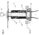
Fig. 3 die Packtulpe ausFigur 2 mit daran angeordneten Linsen, und -
Fig. 4 eine Packtulpe in einer weiteren Ausgestaltung in einem Längsschnitt. - In den unterschiedlichen Figuren sind gleiche Teile stets mit denselben Bezugszeichen versehen, weswegen diese in der Regel auch nur einmal beschrieben werden.
-
Figur 1 zeigt eine Behälterbehandlungsvorrichtung in einer beispielhaften Ausgestaltung als Etikettiermaschine bzw. Etikettierkreisel. Die Behälterbehandlungsvorrichtung weist mehrere Zentriervorrichtungen 2 mit jeweils einer Standfläche 3 und jeweils einer Packtulpe 4 auf. - Die Standfläche 3 ist in bekannter Weise als Drehteller 3 ausgeführt, wobei die Packtulpe 4 an einer Antriebsvorrichtung 6 heb- und/oder drehbar gelagert ist. Mit den Zentriervorrichtungen 2 werden Behälter 7 (
Figuren 2 bis 4 ), zum Beispiel Flaschen um die Mittelachse X der Behälterbehandlungsvorrichtung rotiert, und zum Beispiel Etikettieraggregaten zugeführt. Dabei stehen die Behälter 7 fußseitig auf dem jeweiligen Drehteller 3 und werden kopfseitig mittels der Packtulpe 4 gehalten. In denFiguren 2 bis 4 sind die Behälter 7, bzw. Flaschen lediglich ausschnittsweise mit ihrem Halsbereich gezeigt. - Die Behälterbehandlungsvorrichtung weist eine feststehende Kopfplatte 8 und ein Erfassungs- und Steuersystem 9 auf, welches ein optisches System 10, in der beispielhaften Ausgestaltung als Kamera 10, und eine Bildverarbeitungs- und Steuereinheit 11 aufweist.
- Das optische System 10 ist stationär an der Behälterbehandlungsvorrichtung in der Zeichnungsebene oberhalb der Kopfplatte 8 angeordnet, und in geeigneter Weise festgelegt. Korrespondierend zur Anordnung des optischen Systems 10 ist in der Kopfplatte 8 eine Plattenöffnung 12 eingebracht, so dass das optische System 10 von oben durch die Kopfplatte 8 hindurch auf die Packtulpen 4, bzw. durch diese hindurch schauen kann, worauf weiter eingegangen wird, und was mittels den Linien 13 angedeutet ist. Der Strahlengang des optischen Systems 10 durch die Packtulpe 4 hindurch ist in den
Figuren 2 bis 4 dargestellt. Wesentlich ist, dass mit dem oberhalb der Kopfplatte 8 angeordneten optischen System 10 durch die Plattenöffnung 12 und durch die Packtulpe 4 hindurch Verschlussansichten bzw. Deckelsitzinspektionen ermöglicht werden, wozu günstigen falls ein einziges, stationäres optisches System 10 bzw. eine einzige, stationäre Kamera 10 notwendig ist, um die Verschlussansichten der vorbeilaufenden Behälter 7 zu erhalten. InFigur 1 sind der Übersicht wegen weitere Zentriervorrichtungen 2 der Etikettiermaschine 1 nicht dargestellt. - Die Behälterbehandlungsvorrichtung weist eine stationär angeordnete Lichtquelle 14 auf, welche an einer Befestigungsvorrichtung 15 so angeordnet und ausgeführt ist, dass eine Tulpenglocke 16 der Packtulpe 4 beleuchtet wird, wenn diese an der Lichtquelle 14 vorbeigeführt wird. Die Lichtquelle 14 weist dazu zwei seitlich zur Tulpengiocke 16 angeordnete Beleuchtungsmittel 17 auf, welche jeweils gepulst einen Lichtstrahl 18 aussenden können, der in
Figur 1 prinzipiell als Lichtblitz 18 dargestellt ist. Die Befestigungsvorrichtung 15 ist bevorzugt gabelartig mit zwei Gabelstegen ausgeführt, an denen jeweils ein Beleuchtungsmittel 17 korrespondierend zur Tulpenglocke 16 angeordnet ist, wobei das jeweilige Beleuchtungsmittel 17 quasi seitlich zur vorbeifahrenden Tulpenglocke 16 den Lichtblitz 18 erzeugt, und die Tulpenglocke 16 indirekt beleuchtet. - Wie
Figur 2 zeigt, ist die jeweilige Packtulpe 4 als hohlwellige Packtulpe 4 ausgeführt, welche sowohl kopfseitig als auch fußseitig, also auch im Bereich der Tulpenglocke 16 Durchsichtöffnungen 19 aufweist. Insofern kann das optische System 10 bzw. die Kamera 10 von oben durch die Kopfplatte 8 und durch die hohlwellige Packtulpe 4 auf ein Verschlusselement 20, in der beispielhaften Ausgestaltung als Kronkorken, blicken, welcher seitlich, also an seiner schrägen Außenfläche mit der Tulpenglocke 16 in Kontakt steht. InFigur 2 ist der Übersicht wegen dieser Kontakt nicht dargestellt. - Die Tulpenglocke 16 ist zumindest teilweise, insbesondere vollständig aus einem transparenten Material, beispielsweise aus einem Plexiglas oder aus MakroIon gebildet. Die Packtulpe 4 weist einen Tulpenhalter 21 auf, welcher von einem Kunststoffrohr 22 umfasst ist.
- Wird nun die entsprechende Packtulpe 4 an der Lichtquelle 14 und dem optischen System 10 vorbeigeführt, senden die Beleuchtungsmittel 17 den Lichtblitz 18 aus, so dass das emittierte Licht radial seitlich in die Tulpenglocke 16 eingekoppelt wird. Die Tulpenglocke 16 ist vorteilhaft als Lichtleitelement 6 ausgeführt, bzw. aus einem lichtleitenden Material (Lichtleitelement) 6 gebildet, so dass das eingekoppelte Licht an der Innenfläche der Tulpenglocke 16 ausgekoppelt wird, und den Innenbereich 23 der Tulpenglocke 16 ausleuchtet. So kann das optische System 10 auf die ausgeleuchtete Deckelseite 24 des Verschlusselementes 20 schauen und ein entsprechendes Bild aufnehmen. Hierzu sind die Lichtquelle 14 und das optische system 10, also die Kamera 10 über die Bildverarbeitungs- und Steuereinheit 11 miteinander verbunden, was mittels der gestrichelten Linie 25 angedeutet ist. So ist z.B. sichergestellt, dass Blitzlicht 18 und Bildaufnahme synchron erfolgen können, also dass eine Bildaufnahme bei beleuchtetem Verschlusselement 20 erfolgen kann. Beispielsweise kann an der Deckelseite 24 ein Dekor oder andere Gestaltungsmerkmale aufgebracht sein. Das von dem optischen System 10 aufgenommene Ist-Bild wird der Bildverarbeitungs- und Steuereinheit 11 zugeleitet in welcher die gelieferten Bilder oder Bilddaten ausgewertet werden. Die Verarbeitung der gelieferten Bilder oder Bilddaten erfolgt beispielsweise durch Vergleich mit in der Bildverarbeitungs- und Steuereinheit 11 abgespeicherten Solldaten. Die Bildverarbeitungs- und Steuereinheit 11 ist beispielsweise ein Rechner oder eine rechnergestützte Einheit mit entsprechenden Eingängen für analoge oder digitale von dem optischen System 10 gelieferten Daten. Weiter weist die Bildverarbeitungs- und Steuereinheit 11 einen nicht dargestellten Ausgang auf, welcher zum Beispiel mit der Antriebsvorrichtung 5 der jeweiligen Packtulpe 4 verbunden sein kann, um den Behälter 7 in einer Sollposition zu positionieren, also um ein entsprechendes Verdrehen des an der Packtulpe 4 gehaltenen Behälters 7 in die gewünschte Position zu erreichen. Möglich ist auch, wenn die Bildverarbeitungs- und Steuereinheit 11 mit dem Drehteller 3 in Verbindung steht, um so eine neu Positionierung des darauf aufstehenden Behälters 7 zu erreichen. Zudem können von der Bildverarbeitungs- und Steuereinheit 11 Kontrollen hinsichtlich der Sitzqualität des Verschlusselementes 20 auf der Behältermündung durchgeführt werden, um so Behälter 7 mit fehlsitzenden Verschlusselementen 20 nachfolgend gegebenenfalls von einer Etikettierung freizuhalten und/oder nachfolgend ausschleusen zu können.
- Wie der
Figur 2 weiter entnommen werden kann, ist dem stationären, optischen System 10 bzw. der Kamera 10 noch ein Kollimator 25 zugeordnet. Der Tulpenhalter 21 ist als Hohlrohr mit kopfseitig angeordnetem Flansch ausgeführt. Der Strahlengang 26 des optischen Systems 10 bzw. der Kamera 10 ist mittels der gestrichelten Linien 26, welche den Linien 13 ausFigur 1 entsprechen, dargestellt. - In
Figur 3 weist die hohlwellige Packtulpe 4 kopfseitig sowie fußseitig jeweils Linsen 27 und 28 auf, wobei die Linse 27 als Eintrittslinse 27 an der kopfseitigen Durchsichtöffnung 19 angeordnet ist. Beide Linsen 27 und 28 sind in dem hohlwelligen Tulpenhalter 21 angeordnet, wobei die Linse 28 als Austrittslinse 28 ausgeführt ist. - Eine weitere Ausgestaltung der hohlwelligen Packtulpe 4 zeigt
Figur 4 . - Die hohlwellige Packtulpe 4 weist wie zuvor einen hohlen Tulpenhalter 21 auf, welcher im Längsschnitt gesehen zylinderförmig ausgeführt ist. Dieser ist beispielhaft von einem inneren Schutz- und Führungsrohr 29 umfasst, welches fußseitig mit dem Tulpenhalter 21 bündig abschließt. Das innere Schutz- und Führungsrohr 29 ist lediglich optional, und besteht aus einem Kunststoff, wohin gegen der Tulpenhalter 21, wie zuvor, aus einem Edelstahl gebildet sein kann. Natürlich sind genannte Materialangaben lediglich beispielhaft zu verstehen. Das optionale Schutz- und Führungsrohr 29 ist außenseitig von einem Lichtleitelement 30 umfasst. Das Lichtleitelement 30 ist beispielhaft als Plexiglasrohr ausgeführt, kann aber auch aus einem Faserbündel bestehen.
- Das Lichtleitelement 30 erstreckt sich von der Kopfseite der Packtulpe 4 in Richtung zur gegenüberliegenden Fußseite, wobei das Lichtleitelement 30 mit einem Überstand 31 über die untere Kante des Tulpenhalters 21 und des optionalen Schutz- und Führungsrohrs 29 übersteht. Das Lichtleitelement 30 ist außenseitig von einem äußeren Schutzrohr 32 umgeben. Mit dem äußeren Schutzrohr 32 steht die Tulpenglocke 16 in Verbindung. Bei dieser Ausgestaltung kann die Tulpenglocke 16 aus einem Standardmaterial gebildet sein, muss also nicht als Lichtleitelement ausgeführt sein.
- Kopfseitig ist dem Lichtleitelement 30 die Lichtquelle 14 zugeordnet, welche in diesem Ausführungsbeispiel als Ringlichtbeleuchtung 33 ausgeführt ist. Diese Ringlichtbeleuchtung kann bspw. als ein LED-Kranz aus einer Vielzahl von Einzel-LED gebildet sein. Die Ringlichtbeleuchtung 33 ist so ausgeführt und angeordnet, dass emittiertes Licht direkt und rundum gleichmäßig kopfseitig in das Lichtleitelement 30 eingekoppelt wird. Die Lichtquelle 14, bzw. die Ringlichtbeleuchtung 33 kann konstant leuchten, kann aber auch mit der Bildverarbeitungs- und Steuereinheit 11 in Verbindung zu stehen, um so synchron zur Bildaufnahme des optischen Systems 11 aufzuscheinen bzw. aufzublitzen.
- Über das Lichtleitelement 30 wird das eingekoppelte Licht in Richtung zum Überstand 31 geleitet, wo das Licht ausgekoppelt wird, und den Innenbereich 23 der Tulpenglocke 16 ausleuchtet. Insofern kann das optionale Schutz- und Führungsrohr 29 bzw. der Tulpenhalter 21 mit seinem zylindrischen Abschnitt und/oder das äußere Schutzrohr 32 auch als Abdeckelement bzw. Abdeckung für das Lichtleitelement 30 bezeichnet werden, welches eine Lichtauskopplung aus dem Lichtleitelement 30 in Hochrichtung gesehen vor dem Überstand 31 nach innen bzw. nach außen vermeiden kann.
- Wie bereits gesagt, tritt das kopfseitig eingekoppelte Licht an dem Überstand 31 aus dem Lichtleitelement 30 nach innen aus. Bevorzugt wird das Licht hier mittels mehrfach Reflexionen seitlich schräg ausgekoppelt. Wie in
Figur 4 beispielhaft dargestellt, kann das Lichtleitelement 30 an seinem Überstand 31 einen Anschliff aufweisen, so dass quasi ein Prisma 34 bzw. ein Streuprisma 34 gebildet ist, um so eine homogene Ausleuchtung des Innenbereichs bzw. ein homogenes Anleuchten des Verschlusselementes 20 bzw. seines deckelseitigen Dekors zu erreichen. Das Prisma 34 kann auch als separates Element ausgeführt sein, und in geeigneter Weise an der Innenfläche des Überstandes 31 festgelegt sein. Möglich ist auch, die Innenfläche des Überstandes 31 bzw. des Prismas 34 mit einem Diffusormaterial zu belegen. Eine homogene Ausleuchtung ist insbesondere bei spiegelnden Oberflächen sinnvoll. - Natürlich kann auch bei dem Ausführungsbeispiel zu
Figur 4 Linsen 27 bzw. 28 wie bei dem Ausführungsbeispiel zuFigur 3 vorgesehen werden. - Die in
Figur 5 gezeigte Variante der erfindungsgemäßen Vorrichtung sieht einen Durchsichtzylinder 35 vor, der aus dem gleichen Material wie die Deckelsichtstulpe 16 oder einem anderen geeigneten transparenten Material gefertigt ist. In dem inFigur 5 gezeigten Beispiel hat dieser Durchsichtzylinder 35 keine konkaven oder konvexen Eigenschaften, diese können aber durch geeignete Schliffe an den Stirnseiten vorsehen werden, um vorteilhafte Linseneffekte zu erreichen. - Die Ringlichtbeleuchtung 33 ist in der gezeigten Variante mehrstöckig ausgeführt bzw. angeordnet, so dass emittiertes Licht direkt und rundum gleichmäßig kopfseitig in den Durchsichtzylinder 35 eingekoppelt wird. Die Ringlichtbeleuchtung 33 ist mit nicht dargestellten Leitungen elektrisch- und steuerungstechnisch verbunden. Die Lichtquelle 14, bzw. die Ringlichtbeleuchtung 33 kann konstant leuchten, kann aber auch mit der Bildverarbeitungs- und Steuereinheit 11 in Verbindung zu stehen, um so synchron zur Bildaufnahme des optischen Systems 11 aufzuscheinen bzw. aufzublitzen. Natürlich kann auch eine Beleuchtung vorgesehen werden, die analog dem in
Figur 2 gezeigten Beispiel von außen Licht in die Tulpeglocke 16 und nachfolgend in den Durchsichtzylinder 35 einkoppelt. - Für eine optimale Lichteinkopplung in den Durchsichtzylinder 35 und nachfolgenden Ausleuchtung des gewünschten Untersuchungsfensters, z.B. einen Kronkorken 20, ist es ggf. nötig, die äußere Zylinderfläche des Durchsichtzylinder 35 im Bereich der Ringleuchte 33 aufzurauen oder anzuätzen, so dass Reflexionen vermieden werden. Insbesondere ist es von Vorteil, die Stirnseiten 36 und 37 des Durchsichtzylinders 35 hochwertig zu polieren, z.B. mittels eines Elektropolierverfahrens, um optimale optische Eigenschaften zu erreichen. Natürlich kann es vorgesehen werden, die Tulpe 16 und den Durchsichtzylinder 35 aus einem einzigen Stück zu fertigen.
- Der Vorteil der Version gemäß
Figur 5 besteht darin, dass im Inneren der ansonsten holen Packtulpe 4 keine Verschmutzungen oder Anlagerungen stattfinden können. - Mit der Erfindung wird die Möglichkeit geboten, mittels zumindest einer Lichtquelle 14 in Zusammenwirken mit dem jeweiligen Lichtleitelement 6 bzw. 30 bzw. mit der erfindungemäßen, zumindest teilweisen lichtleitenden Ausbildung der Packtulpe 4 bzw. mit der vorteilhaften Ausgestaltung der Packtulpe 4 mit lichtleitenden Elementen, das Verschlusselement 20, bzw. dessen deckelseitiges Dekor auszuleuchten, wobei mittels der Kamera 10 das Bild des Verschlusselements 20, bzw. dessen deckelseitigen Dekors von oben durch die Kopfplatte 8 und durch die Packtulpe 4 hindurch abgebildet wird, um das aufgenommene Bild zu Inspektionszwecken zu nutzen. Beispielweise kann der Behälter 7 nach Deckelmerkmalen ausgerichtet werden, wobei auch eine Qualitätskontrolle (Deckelsitz) durchführbar ist. Auch ist das Verschlusselement 20 mittels der Packtulpe bzw. der Tulpenglocke in die gewünschte Position überführbar (Verschließer).
- Insofern ist die Behelterbehandlungsvorrichtung nicht auf die beschriebene Etikettiermaschine beschränkt. Beispielsweise kann die Behälterbehandlungsvorrichtung auch als Verschließer ausgeführt sein, bei welcher mit der Erfindung Verschlussansichten durch eine Plattenöffnung von oben durch die Packtulpe 4 hindurch ermöglicht werden. Insbesondere können naturlich auch die einzelnen Elemente der Packtulpe 4, wie diese an dem jeweiligen Beispiel der
Figuren 1 bis 5 gezeigt sind, in geeigneter Weise untereinander kombiniert, ersetzt oder ergänzt gezeigt werden, ohne dadurch den durch die nachfolgenden Ansprüche definierten Schutzumfang zu verlassen. -
- 2
- Zentriervorrichtung
- 3
- Standfläche (Drehteller)
- 4
- Packtulpe
- 5
- Antriebsvorrichtung
- 6
- Lichtleitelement
- 7
- Behälter
- 8
- Kopfplatte v. 1
- 9
- Erfassungs- Steuersystem
- 10
- Optisches System
- 11
- Bildverarbeitungs- und Steuereinheit
- 12
- Plattenöffnung in 8
- 13
- Sichtweg optisches System
- 14
- Lichtquelle
- 15
- Befestigungsvorrichtung für 14
- 16
- Tulpenglocke
- 17
- Beleuchtungsmittel
- 18
- Lichtblitz
- 19
- Durchsichtöffnungen in 4
- 20
- Verschlusselement
- 21
- Tulpenhalter
- 22
- Kunststoffrohr
- 23
- Innenbereich von 16
- 24
- Deckelseite
- 25
- Verbindung 10 und 14 mit 11
- 26
- Strahlengang von 10 in 4
- 27
- Linse+
- 28
- Linse
- 29
- Schutz- und Führungsrohr
- 30
- Llchtleltelement
- 31
- Überstand v. 30
- 32
- Äußeres Schutzrohr
- 33
- Ringlichtbeleuchtung
- 34
- Prisma
- 35
- Durchsichtzylinder
- 36
- Stirnseite
- 37
- Stirnseite
Claims (15)
- Behälterbehandlungsvorrichtung welche zumindest eine Zentriervorrichtung (2) mit einer Standfläche (3) und einer Packtulpe (4) aufweist, und zwar derart, dass Behälter (7) fußseitig auf der jeweiligen Standfläche (3) aufstellbar und mittels der Packtulpe (4) kopfseitig gehalten werden können, wobei zumindest ein Erfassungs- und Steuersystem (9), aufweisend zumindest ein optisches System (10) vorgesehen ist, wobei die Packtulpe (4) sowohl kopfseitig als auch fussseitig Durchsichtöffnungen (19) aufweist, dadurch gekennzeichnet, dass die Packtulpe (4) einen hohlen Tulpenhalter (21) aufweist, durch den der Strahlengang des optischen Systems (10) führt, und in einem Inneren der Packtulpe ein lichtleitendes Element (30) angeordnet ist, das sich von einer Kopfseite in Richtung zu einer dazu gegenüberliegenden Fußseite erstreckt, und den Tulpenhalter außenseitig umfasst, wobei das lichtleitende Element (30) mit einem Überstand (31) über die untere Kante des Tulpenhalters (21) übersteht, und von einem äußeren Schutzrohr (32) außenseitig umgeben ist, und zumindest eine Lichtquelle (14,17; 14,33) vorgesehen Ist, die so angeordnet ist, dass Licht in das lichtleitende Element (30) eingekoppelt wird, wobei ein Innenbereich (23) einer Tulpenglocke (16) der Packtulpe (4) durch sich auskoppelndes Licht ausleuchtbar ist, so dass eine am fussseitigen Ende der Packtulpe (4) anordbare Deckelseite (24) eines mittels der Packtulpe (4) gehalten Behälters durch das optische System (10), und durch die Packtulpe (4) hindurch und mittels des lichtleitenden Elementes (30), inspizierbar ist.
- Behälterbehandlungsvorrichtung nach Anspruch 1 , dadurch gekennzeichnet, dass das optische System (10) stationär angeordnet ist.
- Behälterbehandlungsvorrichtung nach Anspruch 1 oder 2, dadurch gekennzeichnet, dass die zumindest eine Lichtquelle (14,17) stationär angeordnet ist.
- Behälterbehandlungsvorrichtung nach einem der vorhergehenden Ansprüche, dadurch gekennzeichnet, dass die Deckelseite (24) bzw. der ausgeleuchtete Innenbereich (23) mittels des optischen Systems (10) durch eine Plattenöffnung (12) einer Kopfplatte (8) der Behälterbehandlungsvorrichtung (1) und durch die Packtulpe (4) hindurch inspizierbar ist.
- Behälterbehandlungsvorrichtung nach einem der vorhergehenden Ansprüche, dadurch gekennzeichnet, dass das lichtleitende Element (30) aus einem transparentem Stoff, insbesondere einem transparenten Kunststoff, bevorzugt aus Plexiglas oder Macrolon gebildet ist.
- Behälterbehandlungsvorrichtung nach einem der vorhergehenden Ansprüche, dadurch gekennzeichnet, das die Lichtquelle (14,33) als Ringlichtbeleuchtung (33) an der Kopfseite des Lichtleitelementes (30) angeordnet ist.
- Behälterbehandlungsvorrichtung nach einem der vorhergehenden Ansprüche, dadurch gekennzeichnet, dass aus dem Überstand (31) das mittels der Lichtquelle (14,33) eingekoppelte Licht austritt, und den Innenbereich (23) ausleuchtet.
- Behälterbehandlungsvorrichtung nach einem der vorhergehenden Ansprüche, dadurch gekennzeichnet, dass die Lichtquelle (14,17; 14,33) und das optische System (10) so synchronisiert angesteuert werden, dass das optische System (10) stets einen ausgeleuchteten Innenbereich (23) inspiziert.
- Behälterbehandlungsvorrichtung nach einem der vorhergehenden Ansprüche, dadurch gekennzeichnet, dass die Lichtquelle (14,17; 14,33) konstant leuchtet, so dass das lichtleitende Element (30) den Innenbereich (23) konstant ausleuchtet.
- Behälterbehandlungsvorrichtung nach einem der vorhergehenden Ansprüche, dadurch gekennzeichnet, dass kopfseitig und/oder fussseitig im Bereich der Durchsichtöffnungen (19) optische Linsen (27, 28) vorgesehen sind.
- Behälterbehandlungsvorrichtung nach Anspruch 10, dadurch gekennzeichnet, dass fussseitig mindestens eine Linse (28) vorgesehen ist, die die Strahlungen aufweitet, so dass eine Schattenfläche unterhalb der Linse (28) inspizierbar ist, deren Durchmesser grösser ist, als der freie Querschnitt vor der Linse (28).
- Behälterbehandlungsvorrichtung nach einem der vorhergehenden Ansprüche, dadurch gekennzeichnet, dass der innere Kern der Packtulpe (4) aus einem Durchsichtzylinder (35) gebildet ist, welcher aus einem transparenten Material gebildet ist, insbesondere einen transparenten Ku nststoff, Glas oder Kristall.
- Verfahren zur Inspektion von Flaschen, Behältern usw. einer Behälterbehandlungsvorrichtung (1) dadurch gekennzeichnet, dass eine Behälterbehandlungsvorrichtung nach einem der vorbenannten Ansprüche verwendet wird, umfassend zumindest die Schritte:a) Aufsetzen eines Verschlusselementes (20) auf den Behälter (7) in einem Verschliesser;b) Transport bzw. Übergabe des Behälters (7) an eine Etikettiervorrichtung (1);c) Zentrierung des Behälters (7) mittels der Zentriervorrichtung (2), insbesondere aufstehend auf der Standfläche (3) und mittels der den Behälter haltenden Packtulpe (4);d) Deckelsitzinspizierung mittels des optischen Systems (10) durch die Packtulpe (4) hindurch, wobei eine Lichtquelle derart angeordnet ist, dass Licht in die lichtleitenden Elemente der Packtulpe eingekoppelt und in einen Innenbereich (23) einer Tulpenglocke (16) der Packtulpe (4) ausgekoppelt wird, so dass der Innenbereich ausgeleuchtet wird;e) Ausrichten des Behälters (7) gemäß einer erforderlichen Sollposition.
- Verfahren nach Anspruch 13, dadurch gekennzeichnet, dass vor Durchführung des Schrittes d) und/oder e) eine Grobausrichtung des Behälters (7) erfolgt.
- Verfahren nach Anspruch 13 oder 14, dadurch gekennzeichnet, dass in einer Kopfplatte (8) der Behalterbehandlungsvorrichtung (1) eine Plattenöffnung (12) eingebracht ist, durch welches das optische System (10) durch die Packtulpe (4) hindurch die Deckelsitzinspektion durchführt.
Applications Claiming Priority (2)
| Application Number | Priority Date | Filing Date | Title |
|---|---|---|---|
| DE102010012214A DE102010012214A1 (de) | 2010-03-19 | 2010-03-19 | Deckelsichttulpe |
| PCT/EP2010/007501 WO2011113463A1 (de) | 2010-03-19 | 2010-12-09 | Deckelsichttulpe |
Publications (2)
| Publication Number | Publication Date |
|---|---|
| EP2547591A1 EP2547591A1 (de) | 2013-01-23 |
| EP2547591B1 true EP2547591B1 (de) | 2016-03-23 |
Family
ID=43743487
Family Applications (1)
| Application Number | Title | Priority Date | Filing Date |
|---|---|---|---|
| EP10795228.5A Not-in-force EP2547591B1 (de) | 2010-03-19 | 2010-12-09 | Deckelsichttulpe |
Country Status (9)
| Country | Link |
|---|---|
| US (1) | US8804113B2 (de) |
| EP (1) | EP2547591B1 (de) |
| CN (1) | CN102781783B (de) |
| BR (1) | BR112012021989A2 (de) |
| DE (1) | DE102010012214A1 (de) |
| ES (1) | ES2568525T3 (de) |
| PL (1) | PL2547591T3 (de) |
| RU (1) | RU2520040C1 (de) |
| WO (1) | WO2011113463A1 (de) |
Families Citing this family (14)
| Publication number | Priority date | Publication date | Assignee | Title |
|---|---|---|---|---|
| DE102008044926A1 (de) * | 2008-08-29 | 2010-03-25 | Khs Ag | Behälterausrichtung |
| JP6182722B2 (ja) * | 2013-07-17 | 2017-08-23 | キリンテクノシステム株式会社 | 容器の検査装置 |
| CN104555852A (zh) * | 2013-10-16 | 2015-04-29 | 山东工大机械有限公司 | 易拉罐封装自动落盖器 |
| EP2942321A1 (de) * | 2014-05-05 | 2015-11-11 | Sidel S.p.a. Con Socio Unico | Abfüllanlage und Linie zur Führung von Behältern |
| DE102014218363A1 (de) * | 2014-09-12 | 2016-03-17 | Krones Aktiengesellschaft | Vorrichtung und Verfahren zum Direktbedrucken und/oder Etikettieren von Behältern |
| DE102014218361A1 (de) * | 2014-09-12 | 2016-03-17 | Krones Ag | Vorrichtung und Verfahren zum Behandeln von Behältern durch Direktdruck und/oderEtikettierung |
| DE102014224519A1 (de) * | 2014-12-01 | 2016-06-02 | Krones Ag | Etikettiervorrichtung und -verfahren zur Etikettierung von Behältern |
| ES2919139T3 (es) | 2015-02-04 | 2022-07-22 | Syntegon Tech K K | Dispositivo de inspección y sistema de inspección |
| EP3085628A1 (de) * | 2015-04-23 | 2016-10-26 | Sidel Participations, S.A.S. | Einheit und verfahren zum herstellen von mit einem fliessfähigen produkt gefüllten gegenständen |
| ITUA20162898A1 (it) | 2016-04-26 | 2017-10-26 | Sacmi | Macchina etichettatrice di contenitori per liquidi con dispositivo di ispezione ottica |
| IT201700055395A1 (it) * | 2017-05-22 | 2018-11-22 | Telerobot S P A | Dispositivo di montaggio per oggetti plastici |
| CN108328542B (zh) * | 2018-02-05 | 2020-09-18 | 上海达和荣艺包装机械有限公司 | 一种高盖压盖机 |
| JP7392804B1 (ja) * | 2022-10-25 | 2023-12-06 | 株式会社アイシン | 穴検査用レンズユニット |
| CN116690523B (zh) * | 2023-08-04 | 2023-10-17 | 膳魔师(中国)家庭制品有限公司 | 自纠偏定向划线贴标装置及其划线贴标方法 |
Family Cites Families (21)
| Publication number | Priority date | Publication date | Assignee | Title |
|---|---|---|---|---|
| US3479514A (en) * | 1966-09-23 | 1969-11-18 | Anchor Hocking Corp | Method and means for inspecting glass articles |
| US3557950A (en) * | 1968-09-24 | 1971-01-26 | Powers Manufacturing | Photo-electric crack detector for glass bottles |
| US3944058A (en) * | 1973-04-19 | 1976-03-16 | Indian Head Inc. | Bottle conveyor system including adjustable height continuous belt conveyor and positive lock spray shielded rotatable bottle carrier |
| US4323158A (en) * | 1980-07-03 | 1982-04-06 | Wheaton Industries | Bottle neck finish inspection apparatus |
| DE3308489C2 (de) | 1983-03-10 | 1986-07-03 | Krones Ag Hermann Kronseder Maschinenfabrik, 8402 Neutraubling | Zentriervorrichtung für aufrecht stehende Gefäße, insbesondere in Etikettiermaschinen |
| US4915237A (en) * | 1986-09-11 | 1990-04-10 | Inex/Vistech Technologies, Inc. | Comprehensive container inspection system |
| JPS6480802A (en) * | 1987-09-24 | 1989-03-27 | Echo Kk | Bottle mouth inspecting device |
| JP2723983B2 (ja) * | 1989-07-14 | 1998-03-09 | サントリー株式会社 | キャップ締め角度検査装置 |
| JP2946613B2 (ja) | 1990-03-07 | 1999-09-06 | 澁谷工業株式会社 | 容器検査装置の光ガイド |
| US5398898A (en) * | 1993-11-01 | 1995-03-21 | Bever; Damon S. | Holding device |
| US5592286A (en) * | 1995-03-08 | 1997-01-07 | Alltrista Corporation | Container flange inspection system using an annular lens |
| JP3257356B2 (ja) | 1995-07-19 | 2002-02-18 | 富士通株式会社 | 気相成長装置及び気相成長方法並びに気相成長装置のクリーニング方法 |
| DE59712569D1 (de) * | 1996-10-30 | 2006-04-13 | Krones Ag | Inspektionsvorrichtung für flaschen oder dgl. |
| JP2001080802A (ja) | 1999-09-16 | 2001-03-27 | Copyer Co Ltd | 画像形成装置 |
| JP2001221747A (ja) * | 2000-02-03 | 2001-08-17 | Suntory Ltd | 液体充填用容器の撮像方法および装置 |
| DE20115480U1 (de) * | 2001-09-19 | 2002-05-16 | Heuft Systemtechnik Gmbh | Vorrichtung zum Anbringen von Etiketten an Behältern |
| DE202005006755U1 (de) * | 2005-04-26 | 2005-10-20 | Khs Maschinen- Und Anlagenbau Ag | Vorrichtung zur Verschlussausrichtung |
| DE102007025520A1 (de) | 2007-05-31 | 2008-12-04 | Khs Ag | Verfahren zum Ausrichten von Behältern sowie Vorrichtung zum Durchführen des Verfahrens |
| JP4813437B2 (ja) * | 2007-09-18 | 2011-11-09 | 株式会社日立情報制御ソリューションズ | 容器内の異物検出装置および異物検出方法 |
| DE102008044926A1 (de) * | 2008-08-29 | 2010-03-25 | Khs Ag | Behälterausrichtung |
| DE102009003649A1 (de) | 2009-03-20 | 2010-09-23 | Krones Ag | Vorrichtung und Verfahren zur Behälterbehandlung |
-
2010
- 2010-03-19 DE DE102010012214A patent/DE102010012214A1/de not_active Withdrawn
- 2010-12-09 ES ES10795228.5T patent/ES2568525T3/es active Active
- 2010-12-09 BR BR112012021989-8A patent/BR112012021989A2/pt not_active Application Discontinuation
- 2010-12-09 US US13/580,467 patent/US8804113B2/en not_active Expired - Fee Related
- 2010-12-09 EP EP10795228.5A patent/EP2547591B1/de not_active Not-in-force
- 2010-12-09 PL PL10795228.5T patent/PL2547591T3/pl unknown
- 2010-12-09 CN CN201080065171.2A patent/CN102781783B/zh not_active Expired - Fee Related
- 2010-12-09 RU RU2012144404/12A patent/RU2520040C1/ru not_active IP Right Cessation
- 2010-12-09 WO PCT/EP2010/007501 patent/WO2011113463A1/de active Application Filing
Also Published As
| Publication number | Publication date |
|---|---|
| WO2011113463A1 (de) | 2011-09-22 |
| US8804113B2 (en) | 2014-08-12 |
| PL2547591T3 (pl) | 2016-09-30 |
| ES2568525T3 (es) | 2016-04-29 |
| CN102781783A (zh) | 2012-11-14 |
| RU2012144404A (ru) | 2014-04-27 |
| RU2520040C1 (ru) | 2014-06-20 |
| EP2547591A1 (de) | 2013-01-23 |
| US20120314213A1 (en) | 2012-12-13 |
| BR112012021989A2 (pt) | 2020-09-01 |
| CN102781783B (zh) | 2014-10-15 |
| DE102010012214A1 (de) | 2011-09-22 |
Similar Documents
| Publication | Publication Date | Title |
|---|---|---|
| EP2547591B1 (de) | Deckelsichttulpe | |
| EP0873510B1 (de) | Inspektionsvorrichtung für flaschen oder dgl. | |
| EP2369328B1 (de) | Vorrichtung und verfahren zum untersuchen von befüllten behältnissen auf fremdkörper | |
| EP2379439B2 (de) | Verfahren sowie inspektionsvorrichtung zum überprüfen von behältern | |
| DE102012016342A1 (de) | Behälterinneninspektion von unten durch den Boden hindurch | |
| EP2596340B1 (de) | Erfassungssystem zur flaschennaht- und embossingausrichtung und verfahren zur behandlung von flaschen. | |
| DE102014216576A1 (de) | Behälterbehandlungsmaschine mit einer Inspektionsvorrichtung | |
| DE102014217771B4 (de) | Vorrichtung und Verfahren zur Qualitätskontrolle transparenter Objekte | |
| EP2112502B1 (de) | Verfahren und Vorrichtung zur Prüfung von Behälter-Preforms | |
| EP3152550B1 (de) | Inspektionsvorrichtung für behälterverschlüsse | |
| DE102011086099A1 (de) | Inspektion und Rückführung von Behältern | |
| DE3033531A1 (de) | Vorrichtung zur pruefung von glasbehaeltern | |
| DE202016105126U1 (de) | Abfüllanlage für Behälter mit Flüssigkeiten | |
| DE102007054657A1 (de) | Optische Erfassungseinrichtung, insbesondere zur Inspektion von Flaschen, sowie entsprechendes Visualisierungsverfahren | |
| DE102018130940A1 (de) | Vorrichtung und Verfahren zur Drehlageerkennung | |
| EP3260847A2 (de) | Testbehältnis zum testen von inspektionseinrichtungen | |
| DE102006003325A1 (de) | Kastenblende | |
| EP2671649B1 (de) | Vorrichtung zur Identifizierung einer Flasche | |
| DE10146449A1 (de) | Verfahren zur Kontrolle von Verschlüssen auf Gefäßen | |
| DE102007036621A1 (de) | Verfahren und Vorrichtung zur Untersuchung von Flaschen aus Kunststoff oder Glas auf vorgewählte Eigenschaften | |
| DE19920007C1 (de) | Vorrichtung zur Inspektion von Dichtflächen an Flaschen | |
| EP1811288A2 (de) | Vorrichtung und Verfahren zum Inspizieren von Gefässverschlüssen | |
| DE202012104043U1 (de) | Inspektionsvorrichtung für Behältnismündungen | |
| DE102007031749A1 (de) | Erkennungssystem für Markierungen im Schulter- und Halsbereich von Flaschen | |
| EP3980760A1 (de) | Verfahren und vorrichtung zur optischen inspektion von behältern |
Legal Events
| Date | Code | Title | Description |
|---|---|---|---|
| PUAI | Public reference made under article 153(3) epc to a published international application that has entered the european phase |
Free format text: ORIGINAL CODE: 0009012 |
|
| 17P | Request for examination filed |
Effective date: 20121019 |
|
| AK | Designated contracting states |
Kind code of ref document: A1 Designated state(s): AL AT BE BG CH CY CZ DE DK EE ES FI FR GB GR HR HU IE IS IT LI LT LU LV MC MK MT NL NO PL PT RO RS SE SI SK SM TR |
|
| DAX | Request for extension of the european patent (deleted) | ||
| 17Q | First examination report despatched |
Effective date: 20130710 |
|
| GRAP | Despatch of communication of intention to grant a patent |
Free format text: ORIGINAL CODE: EPIDOSNIGR1 |
|
| INTG | Intention to grant announced |
Effective date: 20151008 |
|
| GRAS | Grant fee paid |
Free format text: ORIGINAL CODE: EPIDOSNIGR3 |
|
| GRAA | (expected) grant |
Free format text: ORIGINAL CODE: 0009210 |
|
| AK | Designated contracting states |
Kind code of ref document: B1 Designated state(s): AL AT BE BG CH CY CZ DE DK EE ES FI FR GB GR HR HU IE IS IT LI LT LU LV MC MK MT NL NO PL PT RO RS SE SI SK SM TR |
|
| REG | Reference to a national code |
Ref country code: GB Ref legal event code: FG4D Free format text: NOT ENGLISH |
|
| REG | Reference to a national code |
Ref country code: CH Ref legal event code: EP |
|
| REG | Reference to a national code |
Ref country code: AT Ref legal event code: REF Ref document number: 782897 Country of ref document: AT Kind code of ref document: T Effective date: 20160415 |
|
| REG | Reference to a national code |
Ref country code: IE Ref legal event code: FG4D Free format text: LANGUAGE OF EP DOCUMENT: GERMAN |
|
| REG | Reference to a national code |
Ref country code: ES Ref legal event code: FG2A Ref document number: 2568525 Country of ref document: ES Kind code of ref document: T3 Effective date: 20160429 |
|
| REG | Reference to a national code |
Ref country code: DE Ref legal event code: R096 Ref document number: 502010011287 Country of ref document: DE |
|
| REG | Reference to a national code |
Ref country code: LT Ref legal event code: MG4D |
|
| REG | Reference to a national code |
Ref country code: NL Ref legal event code: MP Effective date: 20160323 |
|
| PG25 | Lapsed in a contracting state [announced via postgrant information from national office to epo] |
Ref country code: GR Free format text: LAPSE BECAUSE OF FAILURE TO SUBMIT A TRANSLATION OF THE DESCRIPTION OR TO PAY THE FEE WITHIN THE PRESCRIBED TIME-LIMIT Effective date: 20160624 Ref country code: NO Free format text: LAPSE BECAUSE OF FAILURE TO SUBMIT A TRANSLATION OF THE DESCRIPTION OR TO PAY THE FEE WITHIN THE PRESCRIBED TIME-LIMIT Effective date: 20160623 Ref country code: FI Free format text: LAPSE BECAUSE OF FAILURE TO SUBMIT A TRANSLATION OF THE DESCRIPTION OR TO PAY THE FEE WITHIN THE PRESCRIBED TIME-LIMIT Effective date: 20160323 Ref country code: HR Free format text: LAPSE BECAUSE OF FAILURE TO SUBMIT A TRANSLATION OF THE DESCRIPTION OR TO PAY THE FEE WITHIN THE PRESCRIBED TIME-LIMIT Effective date: 20160323 |
|
| PG25 | Lapsed in a contracting state [announced via postgrant information from national office to epo] |
Ref country code: RS Free format text: LAPSE BECAUSE OF FAILURE TO SUBMIT A TRANSLATION OF THE DESCRIPTION OR TO PAY THE FEE WITHIN THE PRESCRIBED TIME-LIMIT Effective date: 20160323 Ref country code: LT Free format text: LAPSE BECAUSE OF FAILURE TO SUBMIT A TRANSLATION OF THE DESCRIPTION OR TO PAY THE FEE WITHIN THE PRESCRIBED TIME-LIMIT Effective date: 20160323 Ref country code: LV Free format text: LAPSE BECAUSE OF FAILURE TO SUBMIT A TRANSLATION OF THE DESCRIPTION OR TO PAY THE FEE WITHIN THE PRESCRIBED TIME-LIMIT Effective date: 20160323 Ref country code: SE Free format text: LAPSE BECAUSE OF FAILURE TO SUBMIT A TRANSLATION OF THE DESCRIPTION OR TO PAY THE FEE WITHIN THE PRESCRIBED TIME-LIMIT Effective date: 20160323 Ref country code: NL Free format text: LAPSE BECAUSE OF FAILURE TO SUBMIT A TRANSLATION OF THE DESCRIPTION OR TO PAY THE FEE WITHIN THE PRESCRIBED TIME-LIMIT Effective date: 20160323 |
|
| PG25 | Lapsed in a contracting state [announced via postgrant information from national office to epo] |
Ref country code: IS Free format text: LAPSE BECAUSE OF FAILURE TO SUBMIT A TRANSLATION OF THE DESCRIPTION OR TO PAY THE FEE WITHIN THE PRESCRIBED TIME-LIMIT Effective date: 20160723 Ref country code: EE Free format text: LAPSE BECAUSE OF FAILURE TO SUBMIT A TRANSLATION OF THE DESCRIPTION OR TO PAY THE FEE WITHIN THE PRESCRIBED TIME-LIMIT Effective date: 20160323 |
|
| PG25 | Lapsed in a contracting state [announced via postgrant information from national office to epo] |
Ref country code: PT Free format text: LAPSE BECAUSE OF FAILURE TO SUBMIT A TRANSLATION OF THE DESCRIPTION OR TO PAY THE FEE WITHIN THE PRESCRIBED TIME-LIMIT Effective date: 20160725 Ref country code: RO Free format text: LAPSE BECAUSE OF FAILURE TO SUBMIT A TRANSLATION OF THE DESCRIPTION OR TO PAY THE FEE WITHIN THE PRESCRIBED TIME-LIMIT Effective date: 20160323 Ref country code: SM Free format text: LAPSE BECAUSE OF FAILURE TO SUBMIT A TRANSLATION OF THE DESCRIPTION OR TO PAY THE FEE WITHIN THE PRESCRIBED TIME-LIMIT Effective date: 20160323 Ref country code: SK Free format text: LAPSE BECAUSE OF FAILURE TO SUBMIT A TRANSLATION OF THE DESCRIPTION OR TO PAY THE FEE WITHIN THE PRESCRIBED TIME-LIMIT Effective date: 20160323 Ref country code: CZ Free format text: LAPSE BECAUSE OF FAILURE TO SUBMIT A TRANSLATION OF THE DESCRIPTION OR TO PAY THE FEE WITHIN THE PRESCRIBED TIME-LIMIT Effective date: 20160323 |
|
| REG | Reference to a national code |
Ref country code: FR Ref legal event code: PLFP Year of fee payment: 7 |
|
| REG | Reference to a national code |
Ref country code: DE Ref legal event code: R097 Ref document number: 502010011287 Country of ref document: DE |
|
| PLBE | No opposition filed within time limit |
Free format text: ORIGINAL CODE: 0009261 |
|
| STAA | Information on the status of an ep patent application or granted ep patent |
Free format text: STATUS: NO OPPOSITION FILED WITHIN TIME LIMIT |
|
| PG25 | Lapsed in a contracting state [announced via postgrant information from national office to epo] |
Ref country code: DK Free format text: LAPSE BECAUSE OF FAILURE TO SUBMIT A TRANSLATION OF THE DESCRIPTION OR TO PAY THE FEE WITHIN THE PRESCRIBED TIME-LIMIT Effective date: 20160323 |
|
| PG25 | Lapsed in a contracting state [announced via postgrant information from national office to epo] |
Ref country code: BG Free format text: LAPSE BECAUSE OF FAILURE TO SUBMIT A TRANSLATION OF THE DESCRIPTION OR TO PAY THE FEE WITHIN THE PRESCRIBED TIME-LIMIT Effective date: 20160623 |
|
| 26N | No opposition filed |
Effective date: 20170102 |
|
| PG25 | Lapsed in a contracting state [announced via postgrant information from national office to epo] |
Ref country code: BE Free format text: LAPSE BECAUSE OF NON-PAYMENT OF DUE FEES Effective date: 20161231 Ref country code: SI Free format text: LAPSE BECAUSE OF FAILURE TO SUBMIT A TRANSLATION OF THE DESCRIPTION OR TO PAY THE FEE WITHIN THE PRESCRIBED TIME-LIMIT Effective date: 20160323 |
|
| REG | Reference to a national code |
Ref country code: CH Ref legal event code: PL |
|
| PG25 | Lapsed in a contracting state [announced via postgrant information from national office to epo] |
Ref country code: MC Free format text: LAPSE BECAUSE OF FAILURE TO SUBMIT A TRANSLATION OF THE DESCRIPTION OR TO PAY THE FEE WITHIN THE PRESCRIBED TIME-LIMIT Effective date: 20160323 |
|
| REG | Reference to a national code |
Ref country code: IE Ref legal event code: MM4A |
|
| PG25 | Lapsed in a contracting state [announced via postgrant information from national office to epo] |
Ref country code: LI Free format text: LAPSE BECAUSE OF NON-PAYMENT OF DUE FEES Effective date: 20161231 Ref country code: LU Free format text: LAPSE BECAUSE OF NON-PAYMENT OF DUE FEES Effective date: 20161209 Ref country code: CH Free format text: LAPSE BECAUSE OF NON-PAYMENT OF DUE FEES Effective date: 20161231 |
|
| PG25 | Lapsed in a contracting state [announced via postgrant information from national office to epo] |
Ref country code: IE Free format text: LAPSE BECAUSE OF NON-PAYMENT OF DUE FEES Effective date: 20161209 |
|
| REG | Reference to a national code |
Ref country code: FR Ref legal event code: PLFP Year of fee payment: 8 |
|
| PGFP | Annual fee paid to national office [announced via postgrant information from national office to epo] |
Ref country code: FR Payment date: 20171221 Year of fee payment: 8 Ref country code: DE Payment date: 20171211 Year of fee payment: 8 |
|
| REG | Reference to a national code |
Ref country code: BE Ref legal event code: MM Effective date: 20161231 |
|
| PGFP | Annual fee paid to national office [announced via postgrant information from national office to epo] |
Ref country code: GB Payment date: 20171221 Year of fee payment: 8 Ref country code: PL Payment date: 20171123 Year of fee payment: 8 Ref country code: AT Payment date: 20171221 Year of fee payment: 8 |
|
| PGFP | Annual fee paid to national office [announced via postgrant information from national office to epo] |
Ref country code: ES Payment date: 20180124 Year of fee payment: 8 |
|
| PG25 | Lapsed in a contracting state [announced via postgrant information from national office to epo] |
Ref country code: HU Free format text: LAPSE BECAUSE OF FAILURE TO SUBMIT A TRANSLATION OF THE DESCRIPTION OR TO PAY THE FEE WITHIN THE PRESCRIBED TIME-LIMIT; INVALID AB INITIO Effective date: 20101209 Ref country code: CY Free format text: LAPSE BECAUSE OF FAILURE TO SUBMIT A TRANSLATION OF THE DESCRIPTION OR TO PAY THE FEE WITHIN THE PRESCRIBED TIME-LIMIT Effective date: 20160323 |
|
| PGFP | Annual fee paid to national office [announced via postgrant information from national office to epo] |
Ref country code: IT Payment date: 20171221 Year of fee payment: 8 |
|
| PG25 | Lapsed in a contracting state [announced via postgrant information from national office to epo] |
Ref country code: MK Free format text: LAPSE BECAUSE OF FAILURE TO SUBMIT A TRANSLATION OF THE DESCRIPTION OR TO PAY THE FEE WITHIN THE PRESCRIBED TIME-LIMIT Effective date: 20160323 Ref country code: TR Free format text: LAPSE BECAUSE OF FAILURE TO SUBMIT A TRANSLATION OF THE DESCRIPTION OR TO PAY THE FEE WITHIN THE PRESCRIBED TIME-LIMIT Effective date: 20160323 |
|
| PG25 | Lapsed in a contracting state [announced via postgrant information from national office to epo] |
Ref country code: MT Free format text: LAPSE BECAUSE OF FAILURE TO SUBMIT A TRANSLATION OF THE DESCRIPTION OR TO PAY THE FEE WITHIN THE PRESCRIBED TIME-LIMIT Effective date: 20160323 |
|
| PG25 | Lapsed in a contracting state [announced via postgrant information from national office to epo] |
Ref country code: AL Free format text: LAPSE BECAUSE OF FAILURE TO SUBMIT A TRANSLATION OF THE DESCRIPTION OR TO PAY THE FEE WITHIN THE PRESCRIBED TIME-LIMIT Effective date: 20160323 |
|
| REG | Reference to a national code |
Ref country code: DE Ref legal event code: R119 Ref document number: 502010011287 Country of ref document: DE |
|
| REG | Reference to a national code |
Ref country code: AT Ref legal event code: MM01 Ref document number: 782897 Country of ref document: AT Kind code of ref document: T Effective date: 20181209 |
|
| GBPC | Gb: european patent ceased through non-payment of renewal fee |
Effective date: 20181209 |
|
| PG25 | Lapsed in a contracting state [announced via postgrant information from national office to epo] |
Ref country code: IT Free format text: LAPSE BECAUSE OF NON-PAYMENT OF DUE FEES Effective date: 20181209 Ref country code: DE Free format text: LAPSE BECAUSE OF NON-PAYMENT OF DUE FEES Effective date: 20190702 Ref country code: FR Free format text: LAPSE BECAUSE OF NON-PAYMENT OF DUE FEES Effective date: 20181231 |
|
| PG25 | Lapsed in a contracting state [announced via postgrant information from national office to epo] |
Ref country code: GB Free format text: LAPSE BECAUSE OF NON-PAYMENT OF DUE FEES Effective date: 20181209 Ref country code: AT Free format text: LAPSE BECAUSE OF NON-PAYMENT OF DUE FEES Effective date: 20181209 |
|
| REG | Reference to a national code |
Ref country code: ES Ref legal event code: FD2A Effective date: 20200131 |
|
| PG25 | Lapsed in a contracting state [announced via postgrant information from national office to epo] |
Ref country code: ES Free format text: LAPSE BECAUSE OF NON-PAYMENT OF DUE FEES Effective date: 20181210 |
|
| PG25 | Lapsed in a contracting state [announced via postgrant information from national office to epo] |
Ref country code: PL Free format text: LAPSE BECAUSE OF NON-PAYMENT OF DUE FEES Effective date: 20181209 |