EP2542394B1 - Schneidvorrichtung für einen granulator zum schneiden von granulat - Google Patents
Schneidvorrichtung für einen granulator zum schneiden von granulat Download PDFInfo
- Publication number
- EP2542394B1 EP2542394B1 EP11709665.1A EP11709665A EP2542394B1 EP 2542394 B1 EP2542394 B1 EP 2542394B1 EP 11709665 A EP11709665 A EP 11709665A EP 2542394 B1 EP2542394 B1 EP 2542394B1
- Authority
- EP
- European Patent Office
- Prior art keywords
- cutting device
- cutting
- prong
- fork
- forks
- Prior art date
- Legal status (The legal status is an assumption and is not a legal conclusion. Google has not performed a legal analysis and makes no representation as to the accuracy of the status listed.)
- Active
Links
Images
Classifications
-
- B—PERFORMING OPERATIONS; TRANSPORTING
- B29—WORKING OF PLASTICS; WORKING OF SUBSTANCES IN A PLASTIC STATE IN GENERAL
- B29B—PREPARATION OR PRETREATMENT OF THE MATERIAL TO BE SHAPED; MAKING GRANULES OR PREFORMS; RECOVERY OF PLASTICS OR OTHER CONSTITUENTS OF WASTE MATERIAL CONTAINING PLASTICS
- B29B9/00—Making granules
- B29B9/02—Making granules by dividing preformed material
- B29B9/06—Making granules by dividing preformed material in the form of filamentary material, e.g. combined with extrusion
- B29B9/065—Making granules by dividing preformed material in the form of filamentary material, e.g. combined with extrusion under-water, e.g. underwater pelletizers
-
- B—PERFORMING OPERATIONS; TRANSPORTING
- B29—WORKING OF PLASTICS; WORKING OF SUBSTANCES IN A PLASTIC STATE IN GENERAL
- B29B—PREPARATION OR PRETREATMENT OF THE MATERIAL TO BE SHAPED; MAKING GRANULES OR PREFORMS; RECOVERY OF PLASTICS OR OTHER CONSTITUENTS OF WASTE MATERIAL CONTAINING PLASTICS
- B29B9/00—Making granules
- B29B9/02—Making granules by dividing preformed material
- B29B9/06—Making granules by dividing preformed material in the form of filamentary material, e.g. combined with extrusion
-
- F—MECHANICAL ENGINEERING; LIGHTING; HEATING; WEAPONS; BLASTING
- F16—ENGINEERING ELEMENTS AND UNITS; GENERAL MEASURES FOR PRODUCING AND MAINTAINING EFFECTIVE FUNCTIONING OF MACHINES OR INSTALLATIONS; THERMAL INSULATION IN GENERAL
- F16D—COUPLINGS FOR TRANSMITTING ROTATION; CLUTCHES; BRAKES
- F16D3/00—Yielding couplings, i.e. with means permitting movement between the connected parts during the drive
- F16D3/16—Universal joints in which flexibility is produced by means of pivots or sliding or rolling connecting parts
- F16D3/26—Hooke's joints or other joints with an equivalent intermediate member to which each coupling part is pivotally or slidably connected
- F16D3/38—Hooke's joints or other joints with an equivalent intermediate member to which each coupling part is pivotally or slidably connected with a single intermediate member with trunnions or bearings arranged on two axes perpendicular to one another
- F16D3/40—Hooke's joints or other joints with an equivalent intermediate member to which each coupling part is pivotally or slidably connected with a single intermediate member with trunnions or bearings arranged on two axes perpendicular to one another with intermediate member provided with two pairs of outwardly-directed trunnions on intersecting axes
Definitions
- the invention relates to a cutting device for a granulator for cutting granules emerging from nozzles plastic strands with a knife rotor which is connected via a gimbal-acting hinge piece with drive part and driven part with a drive shaft, in which both the drive part and the output part of a power transmission piece each with a kind of fork in such a way that the forks twisted against each other by 90 degrees enclose the power transmission piece, each fork carries a force transmitting piece passing through the axis and both axes are offset from each other substantially 90 degrees.
- Such a cutting device is from the DE 103 21 723 known.
- three individual composite parts are required to drive from a drive part via a gimbal-acting joint a knife rotor, wherein the power transmission takes place via the joint piece, wherein a drive part via a perpendicular to the drive direction axis operated with two-axis frame, which receives the driving force on an axis and emits a perpendicular thereto extending second axis to a driven part, which latter forms the blade carrier for a cutting device.
- a gimbal-acting joint device which allows articulation directions, as they are also used in the invention is from the European patent application 0 160 319 known.
- the articulated device contains at its center a cube-shaped power transmission, which is penetrated by two axes crossing at an angle of 90 degrees. These axles are each received by a fork piece, which receives the power transmission piece with two arms, in such a way that that the two fork pieces are arranged with their axle mounts rotated 90 degrees against each other, so that from fork to fork a drive and an output at any angle is possible.
- the US 4 260 356 A shows a cutting device according to the preamble of claim 1.
- the invention has for its object to make the above-mentioned cutting device in a knife rotor so that it is designed particularly narrow in the direction of power transmission, whereby they can be advantageously used in granulating, in which usually the space requirement is particularly limited. According to the invention, this is achieved in that the power transmission piece with its two forks is installed in the blade rotor such that one fork is part of the blade rotor and the other fork is part of an axle receptacle for connection to a drive shaft.
- the two forks are integrated into the necessary components of the blade rotor, so that the blade rotor itself is designed to be particularly short in its axial extent, the basic principle is fully maintained that the drive and the output can be done at any angle to each other.
- the two axes of the power transmission piece are placed in a plane.
- the nozzle-facing side of the knife rotor is executed closed.
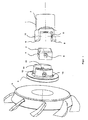
- FIG. 1 the individual parts of the cutting device according to the invention of a first embodiment are shown. These are the fork 1, to which any drive shaft is to be connected, acting as a power transmission cube 2 with the two axial holes 3 and 4, the fork 5 and attached to the fork in any known manner knife rotor 6 with the knives 29th
- the fork 1 has the axle receptacle 7, which is to be connected in any known manner with a drive shaft. From the fork 1 grow the two forks 8 and 9, which maintain such a distance from each other that the cube 2 can be used between the two forks 8 and 9. In this assembly, the cube 2 is inserted so far between the forks 8 and 9, that its axle hole 3 is aligned with the axle holes 10 and 11 in the forks 8 and 9, so that later after composition of all items in the holes 3, 10 and 11 suitable axes can be inserted.
- FIG. 1 further shows the fork 5 with the two forks 12 and 13, which are designed similar to the forks 8 and 9.
- the forks 12 and 13 have such a distance from each other that the cube 2 are inserted between the two forks 12 and 13 can until the hole 4 in the cube 2 is aligned with the axle holes 14 and 15 in the two forks 12 and 13, so that finally an axis can be inserted here.
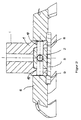
- FIG. 2 shows the compilation of the in the FIG. 1 shown items. Shown is the fork 1, which detects the cube 2 with its two prongs 8 and 9. In this case, the fork 1 is pivotable about a dashed axis, which is inserted into the axle holes 10 and 11.
- FIG. 2 further shows the blade rotor 6, which is firmly connected to the fork 5.
- a drive of the knife rotor 6, which may optionally be angularly offset in relation to the fork 1 in the context of gimbal articulated connection.
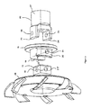
- FIG. 3 and 4 is one compared to the embodiment of the FIGS. 1 and 2 modified design shown in which the power transmission piece 15 detecting forks 19 and 20 are pushed from the same side over the power transmission piece 15 as the forks 23 and 24.
- the power transmission piece 15 is designed in principle in the same way as the power transmission piece 2 according to FIG. 1 , It is provided with the two intersecting bores 16 and 17, which serve to accommodate axes for the rotation on the one hand of a fork 18 and on the other hand, the other fork 22.
- the fork 18 is pushed with its two forks 19 and 20 on the power transmission piece 15, wherein the axial holes 21 and 21 'are aligned. In the fork 18 is how the FIG.
- the fork 22 is inserted with the forks 23 and 24, which thereby include the power transmission piece 15 accordingly, wherein the bore 16 and the bores 25, 26 are aligned.
- the fork 18 has in its space between the forks 19, 20 a sufficiently large space, which allows a corresponding pivotal movement of the forks 23 and 24 of the other fork 22. Accordingly, therefore, the forks 18 and 22 each pivot with respect to the power transmission piece 15, whereby the gimbal mobility of these parts is ensured to each other.
- the fork 22 goes into the drive part 27, which can then be connected to any drive.
- the fork 18 is inserted into a correspondingly shaped receptacle on the blade rotor 28, so that therefore with the corresponding mobility of the fork 18 whose rotation is transmitted to the blade rotor 28.
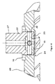
- FIG. 4 is the compilation of in FIG. 3 shown parts exploded shown. It can be seen from that in the FIG. 4 reproduced compilation cardard connection between the drive part 27 and the blade rotor 28 is created. Within the knife rotor 28, the power transmission piece 15 is housed, of which the bore 16 is shown, which is penetrated by an anchored in the forks 23, 24 axis 29.
- Placed holes consists of two stub axles, which are in the relevant outer part, ie either drive part or blade rotor, used, and protrude from there the forks in question in the relevant drive part.
Landscapes
- Engineering & Computer Science (AREA)
- Mechanical Engineering (AREA)
- General Engineering & Computer Science (AREA)
- Processing And Handling Of Plastics And Other Materials For Molding In General (AREA)
- Crushing And Pulverization Processes (AREA)
- Mechanical Operated Clutches (AREA)
- Milling Processes (AREA)
Description
- Die Erfindung bezieht sich auf eine Schneidvorrichtung für einen Granulator zum Schneiden von Granulat von aus Düsen austretenden Kunststoffsträngen mit einem Messerrotor, der über ein kardanisch wirkendes Gelenkstück mit Antriebsteil und Abtriebsteil mit einer Antriebswelle verbunden ist, bei der sowohl das Antriebsteil als auch das Abtriebsteil ein Kraftübertragungsstück jeweils mit einer Art Gabel derart umfassen, dass die Gabeln gegeneinander um 90 Grad verdreht das Kraftübertragungsstück einfassen, wobei jede Gabel eine das Kraftübertragungsstück durchsetzende Achse trägt und beide Achsen gegeneinander im wesentlichen um 90 Grad versetzt sind.
- Eine derartige Schneidvorrichtung ist aus der
DE 103 21 723 bekannt. Gemäß der in Figur 5 dieser Druckschrift dargestellten Schneidvorrichtung sind drei einzelne zusammengesetzte Teile erforderlich, um ausgehend von einem Antriebsteil über ein kardanisch wirkendes Gelenkstück einen Messerrotor anzutreiben, wobei die Kraftübertragung über das Gelenkstück erfolgt, bei dem ein Antriebsteil über eine senkrecht zur Antriebsrichtung verlaufende Achse einen mit zwei Achsen ausgestatteten Rahmen betätigt, der die Antriebskraft über eine Achse aufnimmt und über eine senkrecht dazu verlaufende zweite Achse an ein Abtriebsteil abgibt, welch letzteres den Messerträger für eine Schneidvorrichtung bildet. Es liegt daher eine relativ kompliziert aufgebaute Einrichtung vor, durch die beim Betrieb der Schneidvorrichtung auftretende Achsrichtungsänderungen von einer Antriebswelle auf den Messerrotor durch das Gelenkstück ausgeglichen werden. Es ergibt sich damit eine relativ aufwendige Konstruktion, deren Zusammenbau durch das Einschachteln der einzelnen Teile ineinander erheblich erschwert ist. - Eine kardanisch wirkende Gelenkvorrichtung, die Gelenkrichtungen ermöglicht, wie sie auch bei der Erfindung Verwendung finden, ist aus der europäischen Patentanmeldung
0 160 319 bekannt. Die Gelenkvorrichtung enthält in ihrem Zentrum ein würfelförmiges Kraftübertragungsstück, das von zwei sich im Winkel von 90 Grad kreuzenden Achsen durchsetzt ist. Diese Achsen werden von je einem Gabelstück aufgenommen, das jeweils mit zwei Armen das Kraftübertragungsstück aufnimmt, und zwar derart, dass die beiden Gabelstücke mit ihren Achsaufnahmen um 90 Grad gegeneinander verdreht angeordnet sind, so dass von Gabelstück zu Gabelstück ein Antrieb und ein Abtrieb in jedem beliebigen Winkel möglich ist. DieUS 4 260 356 A zeigt eine Schneidvorrichtung gemäß dem Oberbegriff des Anspruchs 1. - Der Erfindung liegt die Aufgabe zugrunde, die eingangs erwähnte Schneidvorrichtung in einem Messerrotor so zu gestalten, dass diese in der Richtung der Kraftübertragung besonders eng gestaltet ist, wodurch sie vorteilhaft in Granuliervorrichtungen eingesetzt werden kann, in denen üblicherweise der Raumbedarf besonders begrenzt ist. Erfindungsgemäß geschieht dies dadurch, dass das Kraftübertragungsstück mit seinen beiden Gabeln derart in den Messerrotor eingebaut ist, dass die eine Gabel Bestandteil des Messerrotors ist und die andere Gabel Bestandteil einer Achsaufnahme zur Verbindung mit einer Antriebswelle ist.
- Es werden also die beiden Gabeln in die notwendigen Bestandteile des Messerrotors integriert, so dass der Messerrotor selbst in seiner axialen Ausdehnung besonders kurz gestaltet ist, wobei das Grundprinzip vollständig erhalten bleibt, dass der Antrieb und der Abtrieb jeweils in jedem beliebigen Winkel zueinander erfolgen kann. Hierzu werden die beiden Achsen des Kraftübertragungsstücks in eine Ebene gelegt. Vorteilhaft wird dabei die den Düsen zugewandte Seite des Messerrotors geschlossen ausgeführt.
- In den Figuren ist ein Ausführungsbeispiel der Erfindung dargestellt.
- Es zeigen:
- Figur 1
- die Einzelteile der Schneidvorrichtung mit dem Würfel und den zu beiden Seiten dargestellten Gabeln in einer Lage unmittelbar vor dem Zusammenstecken,
- Figur 2
- die in
Figur 1 dargestellten Einzelteile zusammengesteckt zu einer Baugruppe als Schneidvorrichtung für einen Granulator; - Figur 3
- die Einzelteile einer Schneidvorrichtung mit zwei ineinander gesteckten Gabeln;
- Figur 4
- die in
Figur 3 dargestellten Einzelteile zu einer Baugruppe zusammen gesteckt. - In der
Figur 1 sind die Einzelteile der erfindungsgemäßen Schneidvorrichtung eines ersten Ausführungsbeispiels dargestellt. Es handelt sich dabei um die Gabel 1, an die irgend eine Antriebswelle anzuschließen ist, den als Kraftübertragungsstück wirkenden Würfel 2 mit den beiden Achslöchern 3 und 4, der Gabel 5 und dem an der Gabel in irgend einer bekannten Weise befestigten Messerrotor 6 mit den Messern 29. - Die Gabel 1 weist die Achsaufnahme 7 auf, die in irgendeiner bekannten Weise mit einer Antriebswelle zu verbinden ist. Aus der Gabel 1 wachsen die beiden Gabelzinken 8 und 9 heraus, die einen solchen Abstand voneinander einhalten, dass der Würfel 2 passend zwischen die beiden Gabelzinken 8 und 9 eingesetzt werden kann. Bei diesem Zusammenbau wird der Würfel 2 so weit zwischen die Gabelzinken 8 und 9 eingeschoben, dass sein Achsloch 3 mit den Achslöchern 10 und 11 in den Gabelzinken 8 und 9 fluchtet, so dass später nach Zusammensetzung aller Einzelteile in die Bohrungen 3, 10 und 11 passende Achsen eingeschoben werden können.
-
Figur 1 zeigt weiterhin die Gabel 5 mit den beiden Gabelzinken 12 und 13, die ähnlich gestaltet sind wie die Gabelzinken 8 und 9. Die Gabelzinken 12 und 13 weisen einen solchen Abstand voneinander auf, dass der Würfel 2 passend zwischen die beiden Gabelzinken 12 und 13 eingeschoben werden kann, bis die Bohrung 4 im Würfel 2 mit den Achslöchern 14 und 15 in den beiden Gabelzinken 12 und 13 fluchtet, so dass schließlich auch hier eine Achse eingeschoben werden kann. Damit erhält der betreffende Teil einer Schneidvorrichtung seine endgültige Gestalt, wie sie in derFigur 2 dargestellt ist. -
Figur 2 zeigt die Zusammenstellung der in derFigur 1 dargestellten Einzelteile. Dargestellt ist die Gabel 1, die mit ihren beiden Zinken 8 und 9 den Würfel 2 erfasst. Dabei ist die Gabel 1 um eine gestrichelt gezeichnete Achse schwenkbar, die in die Achslöcher 10 und 11 eingeschoben ist. -
Figur 2 zeigt weiterhin den Messerrotor 6, der mit der Gabel 5 fest verbunden ist. Bei Antrieb über die Gabel 1 ergibt sich somit unter Einbeziehung des Würfels 2 und der Gabel 5 ein Antrieb des Messerrotors 6, der dabei im Rahmen der kardanisch gelenkigen Verbindung gegebenenfalls winkelmäßig etwas gegenüber der Gabel 1 versetzt sein kann. - In den
Figuren 3 und4 ist eine gegenüber dem Ausführungsbeispiel nach denFiguren 1 und2 abgewandelte Gestaltung dargestellt, bei der die das Kraftübertragungsstück 15 erfassenden Gabelzinken 19 und 20 von der gleichen Seite her über das Kraftübertragungsstück 15 geschoben sind wie die Gabelzinken 23 und 24. Das Kraftübertragungsstück 15 ist prinzipiell in gleicher Weise gestaltet wie das Kraftübertragungsstück 2 gemäßFigur 1 . Es ist mit den beiden sich kreuzenden Bohrungen 16 und 17 versehen, die der Aufnahme von Achsen für die Verdrehung einerseits der einen Gabel 18 und andererseits der anderen Gabel 22 dienen. Die Gabel 18 wird mit ihren beiden Gabelzinken 19 und 20 über das Kraftübertragungsstück 15 geschoben, wobei die Achslöcher 21 und 21' miteinander fluchten. In die Gabel 18 ist, wie dieFigur 4 zeigt, die Gabel 22 mit den Gabelzinken 23 und 24 eingeschoben, die dabei das Kraftübertragungsstück 15 entsprechend umfassen, wobei die Bohrung 16 und die Bohrungen 25, 26 miteinander fluchten. Die Gabel 18 besitzt in ihrem Raum zwischen den Gabelzinken 19, 20 einen genügend großen Freiraum, der eine entsprechende Schwenkbewegung der Gabelzinken 23 und 24 der anderen Gabel 22 erlaubt. Demgemäß können also die Gabeln 18 und 22 jeweils gegenüber dem Kraftübertragungsstück 15 schwenken, womit die kardanische Beweglichkeit dieser Teile zueinander gewährleistet ist. Die Gabel 22 geht in das Antriebsteil 27 über, das dann an irgendeinen Antrieb angeschlossen werden kann. Die Gabel 18 ist in eine entsprechend gestaltete Aufnahme an dem Messerrotor 28 eingesetzt, so dass also mit der entsprechenden Beweglichkeit der Gabel 18 deren Drehung auf den Messerrotor 28 übertragen wird. - In der
Figur 4 ist die Zusammenstellung der inFigur 3 auseinandergezogen dargestellten Teile widergegeben. Hieraus ist ersichtlich, dass durch die in derFigur 4 wiedergegebene Zusammenstellung eine kardangelenkmäßige Verbindung zwischen dem Antriebsteil 27 und dem Messerrotor 28 geschaffen ist. Innerhalb des Messerrotors 28 ist das Kraftübertragungsstück 15 untergebracht, von dem die Bohrung 16 dargestellt ist, die von einer in den Gabelzinken 23, 24 verankerten Achse 29 durchsetzt ist. - Es wird darauf hingewiesen, dass wegen der Kreuzung der Bohrungen 3/4 bzw. 16/17 diese Bohrungen von nur einer durchgehenden Achse durchsetzt sind, die dann entweder im Messerrotor oder im Antriebsteil gelagert ist, während die kreuzende andere Achse durch die betreffenden rechtwinklig dazu gelegte Bohrungen aus jeweils zwei Achsstummeln besteht, die in dem betreffenden äußeren Teil, also entweder Antriebsteil oder Messerrotor, eingesetzt sind, und von dort aus den betreffenden Gabelzinken in das betreffende Antriebsteil hineinragen.
Claims (5)
- Schneidvorrichtung für einen Granulator zum Schneiden von Granulat von aus Düsen austretenden Kunststoffsträngen mit einem Messerrotor (6, 28), der über ein kardanisch wirkendes Gelenkstück mit Antriebsteil und Abtriebsteil mit einer Antriebswelle verbunden ist, bei der sowohl das Antriebsteil als auch das Abtriebsteil ein Kraftübertragungsstück (2, 15) jeweils mit einer Art Gabel (1, 5; 18, 22) derart umfassen, dass die Gabeln (1, 5; 18, 22) gegeneinander um 90 Grad verdreht das Kraftübertragungsstück (2, 15) einfassen, wobei jede Gabel (1, 5; 18, 22) eine das Kraftübertragungsstück (2, 15) durchsetzende Achse trägt und beide Achsen gegeneinander im wesentlichen um 90 Grad versetzt sind, dadurch gekennzeichnet, dass das Kraftübertragungsstück (2, 15) mit seinen beiden Gabeln (1,5; 18 22) derart in den Messerrotor (6, 28) eingebaut ist, dass die eine Gabel (5, 18) Bestandteil des Messerrotors (6, 28) ist und die andere Gabel (1, 22) Bestandteil einer Achsaufnahme (7) zur Verbindung mit einer Antriebswelle ist
- Schneidvorrichtung nach Anspruch 1, dadurch gekennzeichnet, dass das Kraftübertragungsstück (2, 15) die Form eines Würfels aufweist.
- Schneidvorrichtung nach Anspruch 2, dadurch gekennzeichnet, dass jeweils zwei gegenüberliegende Seiten des Würfels von den beiden Gabelzinken (8, 9; 12, 13; 23, 24; 19, 20) einer Gabel (1, 5; 18, 22) eingefasst sind.
- Schneidvorrichtung nach einem der Ansprüche 1 bis 3, dadurch gekennzeichnet, dass die beiden Achsen (3, 4; 16, 17) in einer Ebene liegen.
- Schneidvorrichtung nach einem der Ansprüche 1 bis 4, dadurch gekennzeichnet, dass die den Düsen zugewandte Seite des Messerrotors (6) geschlossen ausgeführt ist.
Priority Applications (1)
| Application Number | Priority Date | Filing Date | Title |
|---|---|---|---|
| PL11709665T PL2542394T3 (pl) | 2010-03-05 | 2011-03-07 | Urządzenie tnące dla granulatora do cięcia granulatu |
Applications Claiming Priority (2)
| Application Number | Priority Date | Filing Date | Title |
|---|---|---|---|
| DE102010010368A DE102010010368A1 (de) | 2010-03-05 | 2010-03-05 | Schneidvorrichtung für einen Granulator zum Schneiden von Granulat |
| PCT/EP2011/053369 WO2011107609A1 (de) | 2010-03-05 | 2011-03-07 | Schneidvorrichtung für einen granulator zum schneiden von granulat |
Publications (2)
| Publication Number | Publication Date |
|---|---|
| EP2542394A1 EP2542394A1 (de) | 2013-01-09 |
| EP2542394B1 true EP2542394B1 (de) | 2014-11-26 |
Family
ID=44260182
Family Applications (1)
| Application Number | Title | Priority Date | Filing Date |
|---|---|---|---|
| EP11709665.1A Active EP2542394B1 (de) | 2010-03-05 | 2011-03-07 | Schneidvorrichtung für einen granulator zum schneiden von granulat |
Country Status (9)
| Country | Link |
|---|---|
| US (1) | US8851410B2 (de) |
| EP (1) | EP2542394B1 (de) |
| JP (1) | JP5553912B2 (de) |
| CN (1) | CN102791450B (de) |
| DE (1) | DE102010010368A1 (de) |
| ES (1) | ES2527355T3 (de) |
| PL (1) | PL2542394T3 (de) |
| TW (1) | TWI490103B (de) |
| WO (1) | WO2011107609A1 (de) |
Families Citing this family (2)
| Publication number | Priority date | Publication date | Assignee | Title |
|---|---|---|---|---|
| KR102082189B1 (ko) * | 2013-08-20 | 2020-02-27 | 갈라 인더스트리스 인코포레이티드 | 자체-정렬 절단 허브 조립체를 위한 시스템 및 방법 |
| TWI586511B (zh) | 2016-06-13 | 2017-06-11 | 昆陞機械有限公司 | 造粒機切斷裝置 |
Family Cites Families (15)
| Publication number | Priority date | Publication date | Assignee | Title |
|---|---|---|---|---|
| DE2638126C3 (de) * | 1976-08-25 | 1979-08-23 | Basf Ag, 6700 Ludwigshafen | Vorrichtung zum Granulieren thermoplastischer Kunststoffe |
| JPS55118824A (en) * | 1979-03-08 | 1980-09-12 | Japan Crown Cork Co Ltd | Resin cutting device |
| JPS58191427A (ja) | 1982-04-30 | 1983-11-08 | Sharp Corp | 不純物添加方法 |
| JPS58191427U (ja) * | 1982-06-17 | 1983-12-20 | 入野 幸一 | 自在継手 |
| JPS60234125A (ja) * | 1984-05-04 | 1985-11-20 | Hitachi Ltd | ユニバ−サルジヨイントとその製法 |
| JP3485816B2 (ja) * | 1998-12-09 | 2004-01-13 | 太陽誘電株式会社 | ダイシング装置 |
| JP2000301532A (ja) * | 1999-04-22 | 2000-10-31 | Japan Steel Works Ltd:The | 造粒装置のカッター装置 |
| DE10056991C1 (de) * | 2000-11-17 | 2002-01-24 | Bkg Bruckmann & Kreyenborg Granuliertechnik Gmbh | Verbindung einer Antriebswelle mit der Messerkörpernabe für Unterwassergranulatoren |
| JP4150176B2 (ja) * | 2001-08-13 | 2008-09-17 | 株式会社共立 | プロペラシャフト構造 |
| DE10147159C2 (de) * | 2001-09-25 | 2003-11-13 | Bayer Ag | Messergranulator und Verfahren zur Herstellung von Schnittkörpern |
| JP3747186B2 (ja) * | 2002-05-15 | 2006-02-22 | 株式会社神戸製鋼所 | カッター装置 |
| TWM241566U (en) * | 2003-10-21 | 2004-08-21 | Trulytc Entpr Co Ltd | The composed structure of a foot base on an electric fan |
| TWM337462U (en) * | 2007-11-22 | 2008-08-01 | Chung Shan Inst Of Science | Cutting device |
| JP5209295B2 (ja) * | 2007-12-26 | 2013-06-12 | ライオン株式会社 | 皮膚化粧料組成物 |
| JP4369973B2 (ja) * | 2007-12-27 | 2009-11-25 | 株式会社日本製鋼所 | カッタ装置 |
-
2010
- 2010-03-05 DE DE102010010368A patent/DE102010010368A1/de not_active Withdrawn
-
2011
- 2011-01-31 TW TW100103714A patent/TWI490103B/zh active
- 2011-03-07 US US13/582,711 patent/US8851410B2/en active Active
- 2011-03-07 ES ES11709665.1T patent/ES2527355T3/es active Active
- 2011-03-07 EP EP11709665.1A patent/EP2542394B1/de active Active
- 2011-03-07 CN CN201180010492.7A patent/CN102791450B/zh active Active
- 2011-03-07 JP JP2012555447A patent/JP5553912B2/ja active Active
- 2011-03-07 WO PCT/EP2011/053369 patent/WO2011107609A1/de not_active Ceased
- 2011-03-07 PL PL11709665T patent/PL2542394T3/pl unknown
Also Published As
| Publication number | Publication date |
|---|---|
| CN102791450B (zh) | 2015-04-08 |
| WO2011107609A1 (de) | 2011-09-09 |
| EP2542394A1 (de) | 2013-01-09 |
| PL2542394T3 (pl) | 2015-04-30 |
| US20130037641A1 (en) | 2013-02-14 |
| ES2527355T3 (es) | 2015-01-22 |
| TW201134637A (en) | 2011-10-16 |
| DE102010010368A1 (de) | 2011-11-17 |
| TWI490103B (zh) | 2015-07-01 |
| CN102791450A (zh) | 2012-11-21 |
| US8851410B2 (en) | 2014-10-07 |
| JP5553912B2 (ja) | 2014-07-23 |
| JP2013521156A (ja) | 2013-06-10 |
Similar Documents
| Publication | Publication Date | Title |
|---|---|---|
| DE60106085T2 (de) | Tragbare schere mit motorantrieb | |
| DE102007018337B4 (de) | Schneidvorrichtung mit sich hin- und herbewegenden Klingen | |
| DE69027795T2 (de) | Mähgerät | |
| DE602005003927T2 (de) | Gelenkstellglied und verfahren zur einstellung von zwei teilen eines gelenks eines gelenkstellglieds bezüglich einander | |
| EP2018249A1 (de) | Handwerkzeugmaschine mit einem vibrationsgedämpften handgriff | |
| DE102006016858B4 (de) | Verbindungselement mit Gelenk für ein mehrteiliges Konstruktionsspielzeug | |
| DE102008031132A1 (de) | Elektrisches Kleingerät zum Entfernen von Haaren | |
| DE102009014096A1 (de) | Motorisches Schneidegerät für den Garten mit austauschbaren Schneidblättern | |
| DE102012103587A1 (de) | Handführbare Werkzeugmaschine mit Außengehäuse | |
| EP3303091A1 (de) | Vorrichtung zum verbinden eines kupplungsschafts mit einem wagenkasten eines spurgeführten fahrzeuges | |
| DE69834676T2 (de) | Mähmaschine | |
| DE1529269B1 (de) | Elektrisch betaetigbares Messer | |
| DE69800296T2 (de) | Beschaufelte Rotorscheibe mit dreifüssigen Schaufeln | |
| WO2013091827A1 (de) | Granulator | |
| WO2011107609A1 (de) | Schneidvorrichtung für einen granulator zum schneiden von granulat | |
| EP1809091B1 (de) | Schneidgerät | |
| EP1955747B1 (de) | Kinderspielzeug, insbesondere Kinderfahrzeug mit Ladeschaufel | |
| WO2013053351A1 (de) | Mähwerksvorrichtung | |
| EP2621700A1 (de) | Schneidvorrichtung für einen granulator zum schneiden von granulat von aus düsen austretenden kunststoffsträngen mit einem messerrotor | |
| DE2922579C2 (de) | Mähwerk | |
| AT393342B (de) | Frontmaehwerk | |
| EP1827770B1 (de) | Schere, insbesondere heckenschere | |
| DE69010070T2 (de) | Mähmaschine. | |
| DE2915245C2 (de) | Mähbalken | |
| AT389619B (de) | Messerantrieb fuer einen, ein doppelmesser aufweisenden, am vorderende eines tragarmes befestigten maehbalken fuer motormaehmaschinen |
Legal Events
| Date | Code | Title | Description |
|---|---|---|---|
| PUAI | Public reference made under article 153(3) epc to a published international application that has entered the european phase |
Free format text: ORIGINAL CODE: 0009012 |
|
| 17P | Request for examination filed |
Effective date: 20120713 |
|
| AK | Designated contracting states |
Kind code of ref document: A1 Designated state(s): AL AT BE BG CH CY CZ DE DK EE ES FI FR GB GR HR HU IE IS IT LI LT LU LV MC MK MT NL NO PL PT RO RS SE SI SK SM TR |
|
| DAX | Request for extension of the european patent (deleted) | ||
| GRAP | Despatch of communication of intention to grant a patent |
Free format text: ORIGINAL CODE: EPIDOSNIGR1 |
|
| RIC1 | Information provided on ipc code assigned before grant |
Ipc: B29B 9/06 20060101AFI20140612BHEP Ipc: F16D 3/40 20060101ALI20140612BHEP |
|
| INTG | Intention to grant announced |
Effective date: 20140627 |
|
| GRAS | Grant fee paid |
Free format text: ORIGINAL CODE: EPIDOSNIGR3 |
|
| GRAA | (expected) grant |
Free format text: ORIGINAL CODE: 0009210 |
|
| AK | Designated contracting states |
Kind code of ref document: B1 Designated state(s): AL AT BE BG CH CY CZ DE DK EE ES FI FR GB GR HR HU IE IS IT LI LT LU LV MC MK MT NL NO PL PT RO RS SE SI SK SM TR |
|
| REG | Reference to a national code |
Ref country code: GB Ref legal event code: FG4D Free format text: NOT ENGLISH |
|
| REG | Reference to a national code |
Ref country code: CH Ref legal event code: EP |
|
| REG | Reference to a national code |
Ref country code: AT Ref legal event code: REF Ref document number: 697912 Country of ref document: AT Kind code of ref document: T Effective date: 20141215 |
|
| REG | Reference to a national code |
Ref country code: IE Ref legal event code: FG4D Free format text: LANGUAGE OF EP DOCUMENT: GERMAN |
|
| REG | Reference to a national code |
Ref country code: DE Ref legal event code: R096 Ref document number: 502011005092 Country of ref document: DE Effective date: 20150108 |
|
| REG | Reference to a national code |
Ref country code: ES Ref legal event code: FG2A Ref document number: 2527355 Country of ref document: ES Kind code of ref document: T3 Effective date: 20150122 |
|
| REG | Reference to a national code |
Ref country code: NL Ref legal event code: T3 |
|
| REG | Reference to a national code |
Ref country code: LT Ref legal event code: MG4D |
|
| PG25 | Lapsed in a contracting state [announced via postgrant information from national office to epo] |
Ref country code: NO Free format text: LAPSE BECAUSE OF FAILURE TO SUBMIT A TRANSLATION OF THE DESCRIPTION OR TO PAY THE FEE WITHIN THE PRESCRIBED TIME-LIMIT Effective date: 20150226 Ref country code: IS Free format text: LAPSE BECAUSE OF FAILURE TO SUBMIT A TRANSLATION OF THE DESCRIPTION OR TO PAY THE FEE WITHIN THE PRESCRIBED TIME-LIMIT Effective date: 20150326 Ref country code: PT Free format text: LAPSE BECAUSE OF FAILURE TO SUBMIT A TRANSLATION OF THE DESCRIPTION OR TO PAY THE FEE WITHIN THE PRESCRIBED TIME-LIMIT Effective date: 20150326 Ref country code: LT Free format text: LAPSE BECAUSE OF FAILURE TO SUBMIT A TRANSLATION OF THE DESCRIPTION OR TO PAY THE FEE WITHIN THE PRESCRIBED TIME-LIMIT Effective date: 20141126 Ref country code: FI Free format text: LAPSE BECAUSE OF FAILURE TO SUBMIT A TRANSLATION OF THE DESCRIPTION OR TO PAY THE FEE WITHIN THE PRESCRIBED TIME-LIMIT Effective date: 20141126 |
|
| PGFP | Annual fee paid to national office [announced via postgrant information from national office to epo] |
Ref country code: ES Payment date: 20150325 Year of fee payment: 5 |
|
| REG | Reference to a national code |
Ref country code: PL Ref legal event code: T3 |
|
| PG25 | Lapsed in a contracting state [announced via postgrant information from national office to epo] |
Ref country code: GR Free format text: LAPSE BECAUSE OF FAILURE TO SUBMIT A TRANSLATION OF THE DESCRIPTION OR TO PAY THE FEE WITHIN THE PRESCRIBED TIME-LIMIT Effective date: 20150227 Ref country code: CY Free format text: LAPSE BECAUSE OF FAILURE TO SUBMIT A TRANSLATION OF THE DESCRIPTION OR TO PAY THE FEE WITHIN THE PRESCRIBED TIME-LIMIT Effective date: 20141126 Ref country code: LV Free format text: LAPSE BECAUSE OF FAILURE TO SUBMIT A TRANSLATION OF THE DESCRIPTION OR TO PAY THE FEE WITHIN THE PRESCRIBED TIME-LIMIT Effective date: 20141126 Ref country code: RS Free format text: LAPSE BECAUSE OF FAILURE TO SUBMIT A TRANSLATION OF THE DESCRIPTION OR TO PAY THE FEE WITHIN THE PRESCRIBED TIME-LIMIT Effective date: 20141126 Ref country code: SE Free format text: LAPSE BECAUSE OF FAILURE TO SUBMIT A TRANSLATION OF THE DESCRIPTION OR TO PAY THE FEE WITHIN THE PRESCRIBED TIME-LIMIT Effective date: 20141126 Ref country code: HR Free format text: LAPSE BECAUSE OF FAILURE TO SUBMIT A TRANSLATION OF THE DESCRIPTION OR TO PAY THE FEE WITHIN THE PRESCRIBED TIME-LIMIT Effective date: 20141126 |
|
| PGFP | Annual fee paid to national office [announced via postgrant information from national office to epo] |
Ref country code: PL Payment date: 20150223 Year of fee payment: 5 |
|
| PG25 | Lapsed in a contracting state [announced via postgrant information from national office to epo] |
Ref country code: SK Free format text: LAPSE BECAUSE OF FAILURE TO SUBMIT A TRANSLATION OF THE DESCRIPTION OR TO PAY THE FEE WITHIN THE PRESCRIBED TIME-LIMIT Effective date: 20141126 Ref country code: CZ Free format text: LAPSE BECAUSE OF FAILURE TO SUBMIT A TRANSLATION OF THE DESCRIPTION OR TO PAY THE FEE WITHIN THE PRESCRIBED TIME-LIMIT Effective date: 20141126 Ref country code: EE Free format text: LAPSE BECAUSE OF FAILURE TO SUBMIT A TRANSLATION OF THE DESCRIPTION OR TO PAY THE FEE WITHIN THE PRESCRIBED TIME-LIMIT Effective date: 20141126 Ref country code: DK Free format text: LAPSE BECAUSE OF FAILURE TO SUBMIT A TRANSLATION OF THE DESCRIPTION OR TO PAY THE FEE WITHIN THE PRESCRIBED TIME-LIMIT Effective date: 20141126 Ref country code: RO Free format text: LAPSE BECAUSE OF FAILURE TO SUBMIT A TRANSLATION OF THE DESCRIPTION OR TO PAY THE FEE WITHIN THE PRESCRIBED TIME-LIMIT Effective date: 20141126 |
|
| REG | Reference to a national code |
Ref country code: DE Ref legal event code: R097 Ref document number: 502011005092 Country of ref document: DE |
|
| PLBE | No opposition filed within time limit |
Free format text: ORIGINAL CODE: 0009261 |
|
| STAA | Information on the status of an ep patent application or granted ep patent |
Free format text: STATUS: NO OPPOSITION FILED WITHIN TIME LIMIT |
|
| PG25 | Lapsed in a contracting state [announced via postgrant information from national office to epo] |
Ref country code: LU Free format text: LAPSE BECAUSE OF FAILURE TO SUBMIT A TRANSLATION OF THE DESCRIPTION OR TO PAY THE FEE WITHIN THE PRESCRIBED TIME-LIMIT Effective date: 20150307 Ref country code: MC Free format text: LAPSE BECAUSE OF FAILURE TO SUBMIT A TRANSLATION OF THE DESCRIPTION OR TO PAY THE FEE WITHIN THE PRESCRIBED TIME-LIMIT Effective date: 20141126 |
|
| REG | Reference to a national code |
Ref country code: CH Ref legal event code: PL |
|
| 26N | No opposition filed |
Effective date: 20150827 |
|
| GBPC | Gb: european patent ceased through non-payment of renewal fee |
Effective date: 20150307 |
|
| REG | Reference to a national code |
Ref country code: FR Ref legal event code: ST Effective date: 20151130 |
|
| REG | Reference to a national code |
Ref country code: IE Ref legal event code: MM4A |
|
| PG25 | Lapsed in a contracting state [announced via postgrant information from national office to epo] |
Ref country code: IE Free format text: LAPSE BECAUSE OF NON-PAYMENT OF DUE FEES Effective date: 20150307 Ref country code: GB Free format text: LAPSE BECAUSE OF NON-PAYMENT OF DUE FEES Effective date: 20150307 Ref country code: CH Free format text: LAPSE BECAUSE OF NON-PAYMENT OF DUE FEES Effective date: 20150331 Ref country code: LI Free format text: LAPSE BECAUSE OF NON-PAYMENT OF DUE FEES Effective date: 20150331 |
|
| PG25 | Lapsed in a contracting state [announced via postgrant information from national office to epo] |
Ref country code: SI Free format text: LAPSE BECAUSE OF FAILURE TO SUBMIT A TRANSLATION OF THE DESCRIPTION OR TO PAY THE FEE WITHIN THE PRESCRIBED TIME-LIMIT Effective date: 20141126 Ref country code: FR Free format text: LAPSE BECAUSE OF NON-PAYMENT OF DUE FEES Effective date: 20150331 |
|
| REG | Reference to a national code |
Ref country code: DE Ref legal event code: R082 Ref document number: 502011005092 Country of ref document: DE Representative=s name: PUSCHMANN BORCHERT KAISER KLETTNER PATENTANWAE, DE Ref country code: DE Ref legal event code: R082 Ref document number: 502011005092 Country of ref document: DE Representative=s name: PUSCHMANN BORCHERT BARDEHLE PATENTANWAELTE PAR, DE Ref country code: DE Ref legal event code: R081 Ref document number: 502011005092 Country of ref document: DE Owner name: MAAG AUTOMATIK GMBH, DE Free format text: FORMER OWNER: AUTOMATIK PLASTICS MACHINERY GMBH, 63762 GROSSOSTHEIM, DE |
|
| PG25 | Lapsed in a contracting state [announced via postgrant information from national office to epo] |
Ref country code: MT Free format text: LAPSE BECAUSE OF FAILURE TO SUBMIT A TRANSLATION OF THE DESCRIPTION OR TO PAY THE FEE WITHIN THE PRESCRIBED TIME-LIMIT Effective date: 20141126 |
|
| REG | Reference to a national code |
Ref country code: ES Ref legal event code: FD2A Effective date: 20170427 |
|
| PG25 | Lapsed in a contracting state [announced via postgrant information from national office to epo] |
Ref country code: SM Free format text: LAPSE BECAUSE OF FAILURE TO SUBMIT A TRANSLATION OF THE DESCRIPTION OR TO PAY THE FEE WITHIN THE PRESCRIBED TIME-LIMIT Effective date: 20141126 Ref country code: BG Free format text: LAPSE BECAUSE OF FAILURE TO SUBMIT A TRANSLATION OF THE DESCRIPTION OR TO PAY THE FEE WITHIN THE PRESCRIBED TIME-LIMIT Effective date: 20141126 Ref country code: HU Free format text: LAPSE BECAUSE OF FAILURE TO SUBMIT A TRANSLATION OF THE DESCRIPTION OR TO PAY THE FEE WITHIN THE PRESCRIBED TIME-LIMIT; INVALID AB INITIO Effective date: 20110307 |
|
| PG25 | Lapsed in a contracting state [announced via postgrant information from national office to epo] |
Ref country code: ES Free format text: LAPSE BECAUSE OF NON-PAYMENT OF DUE FEES Effective date: 20160308 Ref country code: PL Free format text: LAPSE BECAUSE OF NON-PAYMENT OF DUE FEES Effective date: 20160307 |
|
| PG25 | Lapsed in a contracting state [announced via postgrant information from national office to epo] |
Ref country code: MK Free format text: LAPSE BECAUSE OF FAILURE TO SUBMIT A TRANSLATION OF THE DESCRIPTION OR TO PAY THE FEE WITHIN THE PRESCRIBED TIME-LIMIT Effective date: 20141126 |
|
| PG25 | Lapsed in a contracting state [announced via postgrant information from national office to epo] |
Ref country code: AL Free format text: LAPSE BECAUSE OF FAILURE TO SUBMIT A TRANSLATION OF THE DESCRIPTION OR TO PAY THE FEE WITHIN THE PRESCRIBED TIME-LIMIT Effective date: 20141126 |
|
| PGFP | Annual fee paid to national office [announced via postgrant information from national office to epo] |
Ref country code: DE Payment date: 20260319 Year of fee payment: 16 |
|
| PGFP | Annual fee paid to national office [announced via postgrant information from national office to epo] |
Ref country code: AT Payment date: 20260320 Year of fee payment: 16 |
|
| PGFP | Annual fee paid to national office [announced via postgrant information from national office to epo] |
Ref country code: BE Payment date: 20260319 Year of fee payment: 16 Ref country code: IT Payment date: 20260324 Year of fee payment: 16 |
|
| PGFP | Annual fee paid to national office [announced via postgrant information from national office to epo] |
Ref country code: NL Payment date: 20260319 Year of fee payment: 16 |
|
| PGFP | Annual fee paid to national office [announced via postgrant information from national office to epo] |
Ref country code: TR Payment date: 20260302 Year of fee payment: 16 |