EP2542370B1 - Stirnfräser und dessen verwendung - Google Patents
Stirnfräser und dessen verwendung Download PDFInfo
- Publication number
- EP2542370B1 EP2542370B1 EP20110707655 EP11707655A EP2542370B1 EP 2542370 B1 EP2542370 B1 EP 2542370B1 EP 20110707655 EP20110707655 EP 20110707655 EP 11707655 A EP11707655 A EP 11707655A EP 2542370 B1 EP2542370 B1 EP 2542370B1
- Authority
- EP
- European Patent Office
- Prior art keywords
- milling cutter
- cutting
- face milling
- cutter according
- hard material
- Prior art date
- Legal status (The legal status is an assumption and is not a legal conclusion. Google has not performed a legal analysis and makes no representation as to the accuracy of the status listed.)
- Active
Links
Images


Classifications
-
- B—PERFORMING OPERATIONS; TRANSPORTING
- B23—MACHINE TOOLS; METAL-WORKING NOT OTHERWISE PROVIDED FOR
- B23C—MILLING
- B23C5/00—Milling-cutters
- B23C5/02—Milling-cutters characterised by the shape of the cutter
- B23C5/06—Face-milling cutters, i.e. having only or primarily a substantially flat cutting surface
-
- B—PERFORMING OPERATIONS; TRANSPORTING
- B23—MACHINE TOOLS; METAL-WORKING NOT OTHERWISE PROVIDED FOR
- B23C—MILLING
- B23C5/00—Milling-cutters
- B23C5/16—Milling-cutters characterised by physical features other than shape
- B23C5/18—Milling-cutters characterised by physical features other than shape with permanently-fixed cutter-bits or teeth
-
- B—PERFORMING OPERATIONS; TRANSPORTING
- B23—MACHINE TOOLS; METAL-WORKING NOT OTHERWISE PROVIDED FOR
- B23C—MILLING
- B23C2200/00—Details of milling cutting inserts
- B23C2200/20—Top or side views of the cutting edge
- B23C2200/203—Curved cutting edges
-
- B—PERFORMING OPERATIONS; TRANSPORTING
- B23—MACHINE TOOLS; METAL-WORKING NOT OTHERWISE PROVIDED FOR
- B23C—MILLING
- B23C2210/00—Details of milling cutters
- B23C2210/04—Angles
- B23C2210/0407—Cutting angles
-
- B—PERFORMING OPERATIONS; TRANSPORTING
- B23—MACHINE TOOLS; METAL-WORKING NOT OTHERWISE PROVIDED FOR
- B23C—MILLING
- B23C2210/00—Details of milling cutters
- B23C2210/04—Angles
- B23C2210/0407—Cutting angles
- B23C2210/0421—Cutting angles negative
- B23C2210/0435—Cutting angles negative radial rake angle
-
- B—PERFORMING OPERATIONS; TRANSPORTING
- B23—MACHINE TOOLS; METAL-WORKING NOT OTHERWISE PROVIDED FOR
- B23C—MILLING
- B23C2210/00—Details of milling cutters
- B23C2210/04—Angles
- B23C2210/0407—Cutting angles
- B23C2210/0442—Cutting angles positive
- B23C2210/045—Cutting angles positive axial rake angle
-
- B—PERFORMING OPERATIONS; TRANSPORTING
- B23—MACHINE TOOLS; METAL-WORKING NOT OTHERWISE PROVIDED FOR
- B23C—MILLING
- B23C2210/00—Details of milling cutters
- B23C2210/08—Side or top views of the cutting edge
- B23C2210/084—Curved cutting edges
-
- B—PERFORMING OPERATIONS; TRANSPORTING
- B23—MACHINE TOOLS; METAL-WORKING NOT OTHERWISE PROVIDED FOR
- B23C—MILLING
- B23C2210/00—Details of milling cutters
- B23C2210/20—Number of cutting edges
- B23C2210/206—Number of cutting edges seven
-
- B—PERFORMING OPERATIONS; TRANSPORTING
- B23—MACHINE TOOLS; METAL-WORKING NOT OTHERWISE PROVIDED FOR
- B23C—MILLING
- B23C2210/00—Details of milling cutters
- B23C2210/28—Arrangement of teeth
- B23C2210/282—Unequal angles between the cutting edges, i.e. cutting edges unequally spaced in the circumferential direction
-
- B—PERFORMING OPERATIONS; TRANSPORTING
- B23—MACHINE TOOLS; METAL-WORKING NOT OTHERWISE PROVIDED FOR
- B23C—MILLING
- B23C2222/00—Materials of tools or workpieces composed of metals, alloys or metal matrices
- B23C2222/04—Aluminium
-
- B—PERFORMING OPERATIONS; TRANSPORTING
- B23—MACHINE TOOLS; METAL-WORKING NOT OTHERWISE PROVIDED FOR
- B23C—MILLING
- B23C2224/00—Materials of tools or workpieces composed of a compound including a metal
- B23C2224/04—Aluminium oxide
-
- B—PERFORMING OPERATIONS; TRANSPORTING
- B23—MACHINE TOOLS; METAL-WORKING NOT OTHERWISE PROVIDED FOR
- B23C—MILLING
- B23C2224/00—Materials of tools or workpieces composed of a compound including a metal
- B23C2224/22—Titanium aluminium carbide nitride (TiAlCN)
-
- B—PERFORMING OPERATIONS; TRANSPORTING
- B23—MACHINE TOOLS; METAL-WORKING NOT OTHERWISE PROVIDED FOR
- B23C—MILLING
- B23C2224/00—Materials of tools or workpieces composed of a compound including a metal
- B23C2224/24—Titanium aluminium nitride (TiAlN)
-
- B—PERFORMING OPERATIONS; TRANSPORTING
- B23—MACHINE TOOLS; METAL-WORKING NOT OTHERWISE PROVIDED FOR
- B23C—MILLING
- B23C2224/00—Materials of tools or workpieces composed of a compound including a metal
- B23C2224/36—Titanium nitride
-
- B—PERFORMING OPERATIONS; TRANSPORTING
- B23—MACHINE TOOLS; METAL-WORKING NOT OTHERWISE PROVIDED FOR
- B23C—MILLING
- B23C2226/00—Materials of tools or workpieces not comprising a metal
- B23C2226/12—Boron nitride
- B23C2226/125—Boron nitride cubic [CBN]
-
- B—PERFORMING OPERATIONS; TRANSPORTING
- B23—MACHINE TOOLS; METAL-WORKING NOT OTHERWISE PROVIDED FOR
- B23C—MILLING
- B23C2226/00—Materials of tools or workpieces not comprising a metal
- B23C2226/31—Diamond
- B23C2226/315—Diamond polycrystalline [PCD]
-
- B—PERFORMING OPERATIONS; TRANSPORTING
- B23—MACHINE TOOLS; METAL-WORKING NOT OTHERWISE PROVIDED FOR
- B23C—MILLING
- B23C2228/00—Properties of materials of tools or workpieces, materials of tools or workpieces applied in a specific manner
- B23C2228/10—Coating
-
- B—PERFORMING OPERATIONS; TRANSPORTING
- B23—MACHINE TOOLS; METAL-WORKING NOT OTHERWISE PROVIDED FOR
- B23C—MILLING
- B23C2240/00—Details of connections of tools or workpieces
- B23C2240/08—Brazed connections
-
- B—PERFORMING OPERATIONS; TRANSPORTING
- B23—MACHINE TOOLS; METAL-WORKING NOT OTHERWISE PROVIDED FOR
- B23C—MILLING
- B23C2240/00—Details of connections of tools or workpieces
- B23C2240/21—Glued connections
-
- B—PERFORMING OPERATIONS; TRANSPORTING
- B23—MACHINE TOOLS; METAL-WORKING NOT OTHERWISE PROVIDED FOR
- B23C—MILLING
- B23C2250/00—Compensating adverse effects during milling
- B23C2250/12—Cooling and lubrication
-
- Y—GENERAL TAGGING OF NEW TECHNOLOGICAL DEVELOPMENTS; GENERAL TAGGING OF CROSS-SECTIONAL TECHNOLOGIES SPANNING OVER SEVERAL SECTIONS OF THE IPC; TECHNICAL SUBJECTS COVERED BY FORMER USPC CROSS-REFERENCE ART COLLECTIONS [XRACs] AND DIGESTS
- Y10—TECHNICAL SUBJECTS COVERED BY FORMER USPC
- Y10T—TECHNICAL SUBJECTS COVERED BY FORMER US CLASSIFICATION
- Y10T407/00—Cutters, for shaping
- Y10T407/14—Cutters, for shaping with means to apply fluid to cutting tool
-
- Y—GENERAL TAGGING OF NEW TECHNOLOGICAL DEVELOPMENTS; GENERAL TAGGING OF CROSS-SECTIONAL TECHNOLOGIES SPANNING OVER SEVERAL SECTIONS OF THE IPC; TECHNICAL SUBJECTS COVERED BY FORMER USPC CROSS-REFERENCE ART COLLECTIONS [XRACs] AND DIGESTS
- Y10—TECHNICAL SUBJECTS COVERED BY FORMER USPC
- Y10T—TECHNICAL SUBJECTS COVERED BY FORMER US CLASSIFICATION
- Y10T407/00—Cutters, for shaping
- Y10T407/15—Rotary broach
-
- Y—GENERAL TAGGING OF NEW TECHNOLOGICAL DEVELOPMENTS; GENERAL TAGGING OF CROSS-SECTIONAL TECHNOLOGIES SPANNING OVER SEVERAL SECTIONS OF THE IPC; TECHNICAL SUBJECTS COVERED BY FORMER USPC CROSS-REFERENCE ART COLLECTIONS [XRACs] AND DIGESTS
- Y10—TECHNICAL SUBJECTS COVERED BY FORMER USPC
- Y10T—TECHNICAL SUBJECTS COVERED BY FORMER US CLASSIFICATION
- Y10T407/00—Cutters, for shaping
- Y10T407/19—Rotary cutting tool
- Y10T407/1906—Rotary cutting tool including holder [i.e., head] having seat for inserted tool
- Y10T407/1908—Face or end mill
-
- Y—GENERAL TAGGING OF NEW TECHNOLOGICAL DEVELOPMENTS; GENERAL TAGGING OF CROSS-SECTIONAL TECHNOLOGIES SPANNING OVER SEVERAL SECTIONS OF THE IPC; TECHNICAL SUBJECTS COVERED BY FORMER USPC CROSS-REFERENCE ART COLLECTIONS [XRACs] AND DIGESTS
- Y10—TECHNICAL SUBJECTS COVERED BY FORMER USPC
- Y10T—TECHNICAL SUBJECTS COVERED BY FORMER US CLASSIFICATION
- Y10T407/00—Cutters, for shaping
- Y10T407/19—Rotary cutting tool
- Y10T407/1946—Face or end mill
-
- Y—GENERAL TAGGING OF NEW TECHNOLOGICAL DEVELOPMENTS; GENERAL TAGGING OF CROSS-SECTIONAL TECHNOLOGIES SPANNING OVER SEVERAL SECTIONS OF THE IPC; TECHNICAL SUBJECTS COVERED BY FORMER USPC CROSS-REFERENCE ART COLLECTIONS [XRACs] AND DIGESTS
- Y10—TECHNICAL SUBJECTS COVERED BY FORMER USPC
- Y10T—TECHNICAL SUBJECTS COVERED BY FORMER US CLASSIFICATION
- Y10T407/00—Cutters, for shaping
- Y10T407/23—Cutters, for shaping including tool having plural alternatively usable cutting edges
-
- Y—GENERAL TAGGING OF NEW TECHNOLOGICAL DEVELOPMENTS; GENERAL TAGGING OF CROSS-SECTIONAL TECHNOLOGIES SPANNING OVER SEVERAL SECTIONS OF THE IPC; TECHNICAL SUBJECTS COVERED BY FORMER USPC CROSS-REFERENCE ART COLLECTIONS [XRACs] AND DIGESTS
- Y10—TECHNICAL SUBJECTS COVERED BY FORMER USPC
- Y10T—TECHNICAL SUBJECTS COVERED BY FORMER US CLASSIFICATION
- Y10T407/00—Cutters, for shaping
- Y10T407/26—Cutters, for shaping comprising cutting edge bonded to tool shank
-
- Y—GENERAL TAGGING OF NEW TECHNOLOGICAL DEVELOPMENTS; GENERAL TAGGING OF CROSS-SECTIONAL TECHNOLOGIES SPANNING OVER SEVERAL SECTIONS OF THE IPC; TECHNICAL SUBJECTS COVERED BY FORMER USPC CROSS-REFERENCE ART COLLECTIONS [XRACs] AND DIGESTS
- Y10—TECHNICAL SUBJECTS COVERED BY FORMER USPC
- Y10T—TECHNICAL SUBJECTS COVERED BY FORMER US CLASSIFICATION
- Y10T409/00—Gear cutting, milling, or planing
- Y10T409/30—Milling
- Y10T409/303752—Process
- Y10T409/303808—Process including infeeding
Definitions
- the invention relates to an end mill with a plurality of plate-shaped hard cutting inserts distributed over the circumference, according to the preamble of claim 1.
- the DE 699 30 449 T2 discloses such an end mill.
- Such face milling cutters are often designed as milling heads in which inserts, for example indexable inserts made of hard metal, ceramic (cermet) or polycrystalline diamond (PCD) are accommodated in the tool carrier.
- inserts for example indexable inserts made of hard metal, ceramic (cermet) or polycrystalline diamond (PCD) are accommodated in the tool carrier.
- the cutting inserts are used in Planfräsköpfen so that an adjustment angle ⁇ r of about 75 ° results, that is, the main cutting edges to the plane to be machined in a plane containing the cutter axis at an angle ⁇ r of about 75 °.
- the cutter axis is perpendicular to the workpiece surface, and lying on the front side of the tool minor cutting produce the surface to be produced.
- the invention is therefore based on the object to further develop a face milling cutter, in particular a milling head, according to the preamble of claim 1 such that with a long service life a better cutting performance can be achieved with good surface quality to be achieved.
- the setting angle ⁇ r is greatly reduced to a value between 10 ° and 30 °, most preferably between 18 ° and 22 °, at the same time the main cutting edge is slightly convex. It has been found that in this way the cutting force can be distributed much better and consequently reduced considerably, resulting in a so-called "neutral cut", that is to say no tensile and compressive loading on the component to be machined.
- the changed course of the main cutting edge results in a lower torque absorption at the spindle, which makes it possible to increase the achievable cutting speeds of the milling cutter to up to 4000 m / min.
- the main cutting edge merges into the secondary cutting edge over a small transition radius, which preferably has a value in the range between 0.5 and 1.5 mm.
- This can further increase the service life of the milling cutter. Because the transition radius is in this way in the center of the sizing section, whereby its life can be significantly increased.
- the performance of the end mill can be further increased if the axial rake angle is chosen to be very positive, preferably in the range between 20 ° and 30 °, particularly preferably between 23 ° and 27 °. With this design, it is possible to further reduce the heat development, since the cutting edges are very positive. At the same time, this ensures that the chip pitch is outside the cutting area.
- transition radius between the main cutting edge and the minor cutting edge influences the chip formation and simultaneously the surface quality of the machined workpiece surface with the simplest measures.
- the hard material cutting insert used is accordingly equipped with an adapted transition radius, whereby an increasing surface quality can be achieved with increasing value of the transition radius.
- the tool can be adapted optimally and according to customer requirements to the particular field of application, ie the desired quality of the machined workpiece surface, without having to change the overall design of the tool.
- a tool is created, which is characterized on the one hand by an improved cutting performance, so that with feed speeds of up to 40 m / min and cutting speeds up to 4000 m / min can be used, especially if aluminum or Aluminum alloys are processed, and can be optimally adapted to the particular application by simple variation of geometry parameters. It has been found that the design of the tool can be maintained even when extremely small and extremely large circle diameter present.
- the tool according to the invention is suitable for circle diameter in the range of 10 to 1400 mm.
- the cutting reaction forces acting on the tool can be further reduced if, according to claim 3, a negative radial rake angle is used which lies in the range between -6 ° and -10 °, preferably between -7 ° and -9 °.
- the cut becomes even softer and smoother, which further improves the smoothness of the tool.
- hard-material cutting inserts with a cutting plate made of polycrystalline diamond or cubic boron nitride (CBN) are particularly suitable for extremely high chip removal rates, ie To achieve feed values.
- CBN cubic boron nitride
- the actual amount of delivery depends on the particular machine tool and the spindle. Basically, however, the structure of the end mill according to the invention is able to significantly increase the cutting performance of the tool for all materials.
- a cutting insert made of hard material When a cutting insert made of hard material is used, it is preferably fastened to a cutting carrier plate, wherein the attachment takes place either via a bond, a soldering or a jamming. It has been found that particularly good cutting conditions can be achieved if the blade carrier plate has a thickness of only 2.3 to 2.9 mm and the insert of hard material has a thickness in the range of 0.4 to 0.6 mm.
- the hard-material cutting insert can be detachably mounted in the pocket of the cutter body, for example screwed or clamped.
- the performance of the tool is increased when the hard material cutting insert is seated in the pocket of the blade carrier by soldering or gluing. Because the flutes can be made larger in this way, which further benefits the chip removal and thus the cutting performance.
- the service life of the milling tool can be improved by a suitable coating of the hard material cutting insert, wherein the type of coating is preferably selected as a function of the material to be machined.
- Advantageous embodiments of the coating are the subject of claim 10.
- the milling tool according to the invention is suitable for the so-called dry machining even with the greatest machining power.
- MMS minimum quantity lubrication
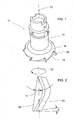
- Fig. 1 is denoted by the reference numeral 12, an end mill, the cylindrical shaft 14 carries a milling head 16.
- the milling head 16 receives in pockets 18 each have a hard material cutting insert 20, wherein the arrangement is made such that in this case all hard material cutting inserts 20 are located on the same pitch circle or circle and are at a predetermined circumferential distance from each other.
- the circumferential distances of adjacent hard cutting inserts 20 differ from each other, that is, the pitch of the milling tool is unequal, whereby the effect is achieved that a self-frequency vibration tendency of the tool is reduced.
- the tool is a so-called face milling head, which is used for face face milling.
- the diameter of the milling head is preferably set to be 1.3 times the width of the workpiece to be machined.
- the special feature of the tool according to Fig. 1 is that the geometry and the position of the hard material cutting inserts 20 are selected relative to the axis of rotation 22 of the tool in a special way. This should be based on the FIGS. 2 to 4 be explained in more detail.
- the arrangement is such that the main cutting edge 24 extends to a plane perpendicular to the cutter axis 22 plane, that is to the working plane 26 of the milling tool at an adjustment angle ⁇ r , in the range between 10 ° and 30 °, preferably between 15 ° and 25 °, most preferably between 18 ° and 22 °.
- This particularly small setting angle ⁇ r causes the main cutting edge 24 at a predetermined measure MZ for the delivery over a relatively large length LE ⁇ MZ sin ⁇ r is in cutting contact. In this way, a relatively large portion of the roughing 28 results, to which a sizing section 30 follows.
- the main cutting edge is slightly convex.
- the contour of the main cutting edge 24 follows at least over the largest extension region a circular arc with a radius of curvature R28, which is in the range between 80 and 120 mm, preferably between 90 and 110 mm, that is for example at 100 mm.
- the main cutting edge 24 merges into the minor cutting edge 32 via a small transition radius R30, which lies in the range between 0.5 and 1.5 mm, that is, for example, 1 mm.
- the transition radius R30 between the main cutting edge 24 and the secondary cutting edge 32 influences the chip formation and at the same time the surface quality of the machined workpiece surface.
- the hard material cutting insert used is accordingly equipped with an adapted transition radius, whereby an increasing surface quality can be achieved with increasing value of the transition radius.
- the tool can be adapted optimally and according to customer requirements to the particular field of application, ie the desired quality of the machined workpiece surface, without having to change the overall design of the tool.
- the hard material cutting insert of the first embodiment shown is an embodiment in which a blade carrier plate 34 has a hard material cutting plate 36 over its entire surface.
- the hard material cutting plate 36 consists for example of polycrystalline diamond (PCD) or cubic boron nitride (CBN).
- PCD polycrystalline diamond
- CBN cubic boron nitride
- Such hard material cutting plates preferably have a thickness of 0.5 mm.
- the blade carrier plate 34 is made of a material which is selected such that it gives the hard material cutting insert 20 a sufficiently high dimensional stability.
- the blade carrier plate 34 is made of solid carbide or a cermet or ceramic material. But it can also consist of other material, even aluminum or carbon fiber reinforced plastic or glass fiber reinforced plastic. It is important that the cutter support plate 34 as fully as possible supported on a support surface of the pocket 18 of the milling head 16, so that the cutting reaction forces can be collected reliably and without material overloads.
- the reference character ⁇ denotes a clearance angle which is to be positive for the main and secondary cutting edge and, for example, lies in the region of 8 °.
- This geometry and configuration of the hard material cutting insert results in greatly improved cutting conditions in the high-speed machining of a wide variety of materials, but especially in the machining of aluminum or aluminum alloys. Due to the relatively large axial rake angle ⁇ a in conjunction with the convex main cutting edge 24, which includes a very small setting angle ⁇ r with the working plane 26, even at Great cutting performance Very good cutting conditions with a very low heat development with good chip pitch, which lies outside the cutting area.
- the hard material cutting insert 20 - as in FIG. 4 shown - is employed in such a plane containing the axis of rotation 22 that results in a negative radial rake angle ⁇ r .
- This radial rake angle is, for example, in the range between -6 ° and -10 °, preferably between -7 ° and -9 °.
- the spindle speed can be in areas above 10000 U / min.
- the feed can be laid in the range of 40m / min, especially if, for example, aluminum and aluminum alloys are processed.
- This embodiment and arrangement of the hard-material cutting inserts on the end mill described above can then be used particularly effectively in an economical manner.
- This shaft 14 is preferably coupled via an HSK interface to the machine spindle or to another system module, which makes it possible to ensure sufficiently high concentricity and vibration stability even at the highest speeds in the range specified above.
- FIGS. 1 to 4 An embodiment of the end mill has been described in which only the core elements of the design are highlighted. The following is based on the FIGS. 5 to 10 a tested further embodiment of the end mill with scale reproduction of the details explained. In order to avoid repetition, similar reference numerals will be used in the description of this embodiment for those components which correspond to the components of the above-described embodiments, but preceded by a "1".
- the face milling cutter designated 112 has a shank 114 with an HSK interface 140.
- the milling head, labeled 116, is made of steel, as is the shank 114.
- Dashed lines 142 indicate an internal channel arrangement for supplying the milling cutters with coolant / lubricant.
- this inner channel arrangement is made such that each cutting edge is assigned a separate lubricant / coolant channel.
- the non-illustrated orifices of the inner cooling channels 142 in the respective pockets 118 are such that the emerging from the mouth openings coolant / lubricant can be used particularly effective for heat dissipation and / or removal of the chips.
- the coolant / lubricant can be a liquid lubricant, but also so-called MMS fluid, which is used in dry machining or in minimum quantity lubrication (MQL technology).
- MQL fluid is, for example, compressed air under a pressure of up to 50 bar, which is mixed with the finest oil droplets.
- the milling head 116 is equipped with seven hard cutting inserts 120, which are at a uniform circumferential distance AU of 51.43 ° to each other.
- the hard material cutting inserts may be constructed as described with reference to FIGS FIGS. 1 to 4 has been described.
- the pockets 118 are formed so that a straight groove of the milling head 116 results.
- H 118 the axial extent of a pocket 118 is designated. It lies for example in a milling head with a diameter of about 130 mm at about 25 to 30 mm.
- the hard material cutting inserts 120 are based on the entire surface of an unspecified support surface of the respective cutting insert associated pocket 118 in the milling head 116 from.
- the thickness D120 of the hard material cutting insert 120 is, for example, 3 mm, while the hard material support, which can consist of PCD or CBN, for example, has a thickness of 0.5 mm. This thickness is designated D136.
- the reference character S denotes the cutting transition between the main cutting edge 124 and the minor cutting edge 132 (see FIG. 8 ), wherein in this section again a small transition radius R130 is formed in the range between 0.5 and 1.5 mm. In the region of this transition radius R130 is the Schtichtschneide, while the roughing edge is formed by the main cutting edge 124th There, the main cutting edge follows a radius of curvature R128, which again assumes values in the range between 80 and 120 mm, preferably between 90 and 110 mm.
- the arrangement is such that at a full surface support of the hard material cutting inserts 120 at corresponding support surfaces of the milling head 116 formed pockets on the main cutting edge negative radial rake angle ⁇ r (see FIG. 6 and FIG. 10 ) of about 8 °.
- the representation after FIG. 10 shows the view in the direction parallel to the orientation of the rake face 138, thus in FIG. 10 appears as a line. In this view, in the illustrated embodiment, the angle ⁇ r is 8 °.
- formed in the pocket 118 support surface for the hard material cutting insert 120 is positioned such that the rake face 138 is inclined to the axis 122 of the mill by an angle of about 25 °.
- the hard material cutting insert 120 is thus arranged such that a relatively large axial rake angle ⁇ a in the range of about 25 ° and a radial rake angle ⁇ r results by 8 °.
- a tool that is constructed and designed according to the above description can have a variety of tool diameters, without changing the basic structure.
- the blade carrier plate can be selected from the group of steel, carbide, aluminum, CFRP and GRP materials. Also, the thickness is not limited to a level around the 2.5 mm. It can vary and be selected depending on the thickness of the hard material insert.
- the hard material insert does not necessarily cover the entire die carrier plate. It is equally possible to work with a cutting insert which extends only in the region of the main and / or the minor cutting edge. Also, the geometry of the hard material cutting plate may be modified, for example, shaped such that a chip breaker function can be fulfilled.
- This coating can be formed, for example, by a hard coating based on TiN, TiAlN, AlTiN, AlCrN and / or Al 2 O 3 .
- This coating can be formed as a single, composite or multilayer coating. It is also possible to work with a hard amorphous carbon layer, ie a so-called DLC layer in accordance with VDI Guidelines VDl3824 Part 1-4 and VDI Guideline 2840: 2004. It is equally possible to provide a soft protective layer, which may be formed by a soft WC / C or a MoS 2 layer.
- these can also be mounted in cassettes, which are in turn mounted on the milling head, for example fixed or adjustable.
- the main field of application of the milling tool according to the invention is the roughing and finishing machining of aluminum or aluminum alloys, wherein cutting speeds up to 4000 mm / min can be realized.
- the arrangement is such that the hard material cutting inserts 120 are distributed over the circumference with the same pitch. It is equally possible to make an uneven pitch, that is, to make the mutual circumferential distance AU of adjacent hard material cutting inserts different in order to further suppress inherent shrinkage of the tool.
Landscapes
- Engineering & Computer Science (AREA)
- Mechanical Engineering (AREA)
- Milling Processes (AREA)
Applications Claiming Priority (2)
| Application Number | Priority Date | Filing Date | Title |
|---|---|---|---|
| DE102010000640A DE102010000640A1 (de) | 2010-03-04 | 2010-03-04 | Stirnfräser |
| PCT/EP2011/053312 WO2011107594A1 (de) | 2010-03-04 | 2011-03-04 | Stirnfräser und dessen verwendung |
Publications (2)
| Publication Number | Publication Date |
|---|---|
| EP2542370A1 EP2542370A1 (de) | 2013-01-09 |
| EP2542370B1 true EP2542370B1 (de) | 2015-05-20 |
Family
ID=44023828
Family Applications (1)
| Application Number | Title | Priority Date | Filing Date |
|---|---|---|---|
| EP20110707655 Active EP2542370B1 (de) | 2010-03-04 | 2011-03-04 | Stirnfräser und dessen verwendung |
Country Status (7)
| Country | Link |
|---|---|
| US (1) | US8979447B2 (enExample) |
| EP (1) | EP2542370B1 (enExample) |
| JP (1) | JP6025569B2 (enExample) |
| KR (1) | KR101863145B1 (enExample) |
| CN (1) | CN102791408A (enExample) |
| DE (1) | DE102010000640A1 (enExample) |
| WO (1) | WO2011107594A1 (enExample) |
Families Citing this family (17)
| Publication number | Priority date | Publication date | Assignee | Title |
|---|---|---|---|---|
| DE102011008998B4 (de) | 2011-01-19 | 2024-07-25 | Mercedes-Benz Group AG | Verfahren zum spanenden Bearbeiten eines Werkstücks |
| DE102011053772B3 (de) * | 2011-09-20 | 2013-02-21 | Optotech Optikmaschinen Gmbh | Verfahren und Vorrichtung zur Bearbeitung eines Kunststoffteils mit einer Drehmaschinenvorrichtung |
| US9578769B2 (en) * | 2012-05-29 | 2017-02-21 | Apple Inc. | Components of an electronic device and methods for their assembly |
| KR101476406B1 (ko) * | 2012-10-26 | 2014-12-26 | 차인선 | 렌즈 가공용 pcd 밀링 커터 |
| EP2740555B1 (en) | 2012-12-07 | 2016-03-16 | Sandvik Tooling France | Cutting tool for face milling, corresponding method of face milling, cutting insert and tool body |
| US9656326B2 (en) * | 2013-04-24 | 2017-05-23 | Iscar, Ltd. | Tool holder having a clamping member with a non-circular cross-section and method for clamping a cutting insert therein |
| USD762739S1 (en) * | 2013-08-15 | 2016-08-02 | Magna-Sonic Stress Testers, Inc. | Pipe end refacing tool |
| DE102013014761B4 (de) * | 2013-09-05 | 2017-06-22 | Audi Ag | Stirnfräswerkzeug |
| DE102014010436A1 (de) * | 2014-07-16 | 2016-01-21 | Leitz Gmbh & Co. Kg | Zerspanungswerkzeug zum Stirnplanfräsen |
| MX369370B (es) * | 2015-04-08 | 2019-11-06 | Decatur Diamond Llc | Fresa con conductos lubricacion. |
| US20180169780A1 (en) | 2016-12-19 | 2018-06-21 | Anvil International, Llc | Cleanline threader |
| US10570501B2 (en) | 2017-05-31 | 2020-02-25 | Kennametal Inc. | Multilayer nitride hard coatings |
| DE102017112374A1 (de) * | 2017-06-06 | 2018-12-06 | Komet Group Gmbh | Fräswerkzeug mit wechselbarem Schneidring |
| CN108515221B (zh) * | 2018-05-17 | 2025-02-14 | 蒋雪峰 | 一种具有加快切削速度功能的高强度铣刀 |
| JP6861755B2 (ja) * | 2019-04-26 | 2021-04-21 | 株式会社牧野フライス製作所 | フライス工具およびワークの加工方法 |
| WO2021073773A2 (en) * | 2019-10-17 | 2021-04-22 | Eaton Intelligent Power Limited | Reverse face angle gear cutter and coolant delivery assembly |
| PL248939B1 (pl) * | 2023-03-24 | 2026-02-16 | Akademia Zamojska | Sposób obróbki wykańczającej matryc kuźniczych ze stali hartowanych narzędziami ceramicznymi |
Family Cites Families (45)
| Publication number | Priority date | Publication date | Assignee | Title |
|---|---|---|---|---|
| US3597817A (en) * | 1969-03-20 | 1971-08-10 | Howard M Whalley | Tee-slot cutter and method for using it |
| US4302135A (en) * | 1980-03-26 | 1981-11-24 | Trw Inc. | Rotary cutting tool |
| US4561810A (en) * | 1981-12-16 | 1985-12-31 | General Electric Company | Bi-level cutting insert |
| JPS5969208A (ja) * | 1982-10-12 | 1984-04-19 | Asahi Malleable Iron Co Ltd | フライス |
| JPS6080811U (ja) * | 1983-11-07 | 1985-06-05 | 東芝タンガロイ株式会社 | スロ−アウエイ式エンドミル |
| JPS60172619U (ja) * | 1984-04-20 | 1985-11-15 | 三菱マテリアル株式会社 | 転削工具用スロ−アウエイチツプ |
| JPH0115456Y2 (enExample) * | 1984-09-27 | 1989-05-09 | ||
| JPH0620657B2 (ja) * | 1985-10-11 | 1994-03-23 | 株式会社東芝 | 正面フライスカツタ |
| US4844666A (en) * | 1986-08-22 | 1989-07-04 | Izumo Industrial Co., Ltd. | Insert rotary cutting tool |
| JPH0825088B2 (ja) * | 1988-06-10 | 1996-03-13 | 東芝タンガロイ株式会社 | 正面フライス用のスローアウェイチップ |
| US5092718A (en) * | 1990-12-10 | 1992-03-03 | Metal Cutting Tools Corp. | Drill with replaceable cutting inserts |
| CH686235A5 (de) * | 1992-10-27 | 1996-02-15 | Alesa Ag | Fraeswerkzeug. |
| JPH0811013A (ja) * | 1994-06-30 | 1996-01-16 | Kyocera Corp | フライス工具 |
| JP2751873B2 (ja) * | 1994-09-22 | 1998-05-18 | 住友電気工業株式会社 | フライス用スローアウェイチップおよびそれを用いたフライス用カッタ |
| US5871850A (en) * | 1994-10-04 | 1999-02-16 | Sumitomo Electric Industries, Ltd. | Coated hard metal material |
| JPH09216113A (ja) * | 1996-02-13 | 1997-08-19 | Sumitomo Electric Ind Ltd | スローアウェイチップおよび切削工具 |
| SE511550C2 (sv) | 1996-10-17 | 1999-10-18 | Seco Tools Ab | Verktyg och skär för fräsning |
| JP3847899B2 (ja) * | 1997-06-10 | 2006-11-22 | 富士重工業株式会社 | 高速切削用回転工具 |
| PT1049411E (pt) * | 1998-01-19 | 2006-09-29 | Michael John Radley Young | Instrumento de corte ultra-sonico |
| JP3395653B2 (ja) * | 1998-06-12 | 2003-04-14 | 三菱マテリアル株式会社 | 不等分割カッタ |
| JP3317490B2 (ja) * | 1998-06-18 | 2002-08-26 | 日立ツール株式会社 | 高送りスローアウェイ式回転工具 |
| JP2000301407A (ja) * | 1999-04-20 | 2000-10-31 | Dijet Ind Co Ltd | スローアウェイ式転削工具 |
| JP4540764B2 (ja) * | 1999-04-27 | 2010-09-08 | 株式会社タンガロイ | 切削工具 |
| US6599062B1 (en) * | 1999-06-11 | 2003-07-29 | Kennametal Pc Inc. | Coated PCBN cutting inserts |
| IL148774A0 (en) * | 2000-07-19 | 2002-09-12 | Sumitomo Electric Industries | Hard sintered compact throwaway tip |
| JP2003117717A (ja) * | 2000-10-27 | 2003-04-23 | Sumitomo Electric Ind Ltd | ワイパーチップおよび回転切削工具用ワイパーチップ |
| US6769844B2 (en) * | 2001-01-10 | 2004-08-03 | Kennametal Inc. | Cutting insert and method of making the same |
| US20020131832A1 (en) * | 2001-03-15 | 2002-09-19 | Morsch Gary L. | Cutting insert with discrete tip and method for producing the same |
| KR100916280B1 (ko) * | 2001-05-25 | 2009-09-10 | 히타치 쓰루 가부시키가이샤 | 날끝 교환식 회전 공구 |
| IL150783A0 (en) * | 2001-10-16 | 2003-02-12 | Iscar Ltd | Cutting tool and cutting insert therefor |
| US6742969B1 (en) * | 2002-12-24 | 2004-06-01 | Kennametal Inc. | Milling cutter insert with chip control and milling cutter using the same |
| DE10357811B4 (de) * | 2002-12-24 | 2006-08-24 | Kennametal Inc. | Fräsereinsatz und Stirnfräser, in dem dieser verwendet wird |
| US7008146B2 (en) * | 2003-07-21 | 2006-03-07 | Kennametal Inc. | Milling cutter with tangentially mounted inserts |
| US7399146B2 (en) * | 2003-09-29 | 2008-07-15 | Kennametal Inc. | Rotary cutting tool having irregular insert orientation |
| JP2005118965A (ja) * | 2003-10-20 | 2005-05-12 | Hitachi Tool Engineering Ltd | インサート及び刃先交換式回転工具 |
| DE10361450A1 (de) * | 2003-12-23 | 2005-07-28 | EMUGE-Werk Richard Glimpel GmbH & Co. KG Fabrik für Präzisionswerkzeuge | Schneidelement und Werkzeug mit wenigstens einem Schneidelement |
| CN100479958C (zh) * | 2004-03-12 | 2009-04-22 | 山特维克知识产权股份有限公司 | 切削刀具和用于切削材料的方法 |
| WO2005089991A1 (en) * | 2004-03-12 | 2005-09-29 | Sandvik Intellectual Property Ab | Cutting tool and method for cutting material |
| US20050271483A1 (en) * | 2004-06-02 | 2005-12-08 | Sandvik Ab | Indexable cutting inserts and methods for producing the same |
| JP2004345081A (ja) * | 2004-07-12 | 2004-12-09 | Kyocera Corp | 回転式切削工具 |
| JP2006181702A (ja) * | 2004-12-28 | 2006-07-13 | Sumitomo Electric Hardmetal Corp | 刃先交換式チップとそれを用いたエンドミル |
| JP4378307B2 (ja) * | 2005-03-23 | 2009-12-02 | 日立ツール株式会社 | 軸方向送り刃先交換式工具 |
| BRPI0721368A2 (pt) * | 2007-02-16 | 2013-01-15 | Taegutec Ltd. | inserto de corte de lado duplo e fresa montando o mesmo |
| CN102046313B (zh) | 2008-06-26 | 2013-03-20 | 塞科机床公司 | 切削刀片套组、铣削刀具和切削刀片 |
| JP4919298B2 (ja) * | 2008-09-19 | 2012-04-18 | 日立ツール株式会社 | 高送り加工用刃先交換式回転工具 |
-
2010
- 2010-03-04 DE DE102010000640A patent/DE102010000640A1/de not_active Withdrawn
-
2011
- 2011-03-04 EP EP20110707655 patent/EP2542370B1/de active Active
- 2011-03-04 CN CN2011800125302A patent/CN102791408A/zh active Pending
- 2011-03-04 WO PCT/EP2011/053312 patent/WO2011107594A1/de not_active Ceased
- 2011-03-04 JP JP2012555439A patent/JP6025569B2/ja not_active Expired - Fee Related
- 2011-03-04 KR KR1020127024742A patent/KR101863145B1/ko active Active
-
2012
- 2012-08-23 US US13/592,895 patent/US8979447B2/en not_active Expired - Fee Related
Also Published As
| Publication number | Publication date |
|---|---|
| DE102010000640A1 (de) | 2011-09-08 |
| JP2013521140A (ja) | 2013-06-10 |
| KR101863145B1 (ko) | 2018-05-31 |
| WO2011107594A1 (de) | 2011-09-09 |
| KR20130006634A (ko) | 2013-01-17 |
| JP6025569B2 (ja) | 2016-11-16 |
| US8979447B2 (en) | 2015-03-17 |
| EP2542370A1 (de) | 2013-01-09 |
| US20130045059A1 (en) | 2013-02-21 |
| CN102791408A (zh) | 2012-11-21 |
Similar Documents
| Publication | Publication Date | Title |
|---|---|---|
| EP2542370B1 (de) | Stirnfräser und dessen verwendung | |
| EP2280797B1 (de) | Schaftfräser | |
| EP1317985B1 (de) | Werkzeug zur Feinstbearbeitung von Oberflächen | |
| EP1334787B1 (de) | Rundlaufschneidwerkzeug | |
| DE69508873T2 (de) | Frässchneideinsatz und Fräser dafür | |
| EP1972399B1 (de) | Kugelbahnfraeser, Werkzeugsystem mit einem Kugelbahnfraeser sowie Verfahren zur Anbringung eines Kugelbahnfraesers | |
| EP0103235B1 (de) | Mehrlippenbohrer | |
| EP2353758B1 (de) | Bearbeitungswerkzeug | |
| EP0692332B1 (de) | Volkeramikbohrer | |
| EP1622735B1 (de) | Bohrwerkzeug zur zerspanung von gusswerkstoffen | |
| DE69930340T2 (de) | Reibahle | |
| WO1996030148A1 (de) | Schneidwerkzeug | |
| EP2929966B1 (de) | Vollfräswerkzeug zur rotierenden Materialbearbeitung | |
| DE69109404T2 (de) | Fingerfräser. | |
| EP0485546B1 (de) | Schneideinsatz für werkzeuge | |
| EP1127645B1 (de) | Schneidwerkzeug | |
| EP3630400A1 (de) | Einlippen-tieflochbohrer mit abgesetzter spanfläche | |
| DE102013226697A1 (de) | Bohrer | |
| EP0912283B1 (de) | Hochgeschwindigkeitsfräsen | |
| DE102008027787A1 (de) | Bohrwerkzeug mit innenliegender Kühl-/Schmiermittelversorgung | |
| DE102005043842A1 (de) | Kugel- oder Torusfräser | |
| WO2007062622A1 (de) | Fräsmesserkopf | |
| JPH05253725A (ja) | エンドミル | |
| DD159407A1 (de) | Messerkopf mit schrupp-und schlichtschneiden | |
| JP2006247774A (ja) | エンドミル |
Legal Events
| Date | Code | Title | Description |
|---|---|---|---|
| PUAI | Public reference made under article 153(3) epc to a published international application that has entered the european phase |
Free format text: ORIGINAL CODE: 0009012 |
|
| 17P | Request for examination filed |
Effective date: 20120925 |
|
| AK | Designated contracting states |
Kind code of ref document: A1 Designated state(s): AL AT BE BG CH CY CZ DE DK EE ES FI FR GB GR HR HU IE IS IT LI LT LU LV MC MK MT NL NO PL PT RO RS SE SI SK SM TR |
|
| DAX | Request for extension of the european patent (deleted) | ||
| GRAP | Despatch of communication of intention to grant a patent |
Free format text: ORIGINAL CODE: EPIDOSNIGR1 |
|
| INTG | Intention to grant announced |
Effective date: 20141204 |
|
| GRAS | Grant fee paid |
Free format text: ORIGINAL CODE: EPIDOSNIGR3 |
|
| GRAA | (expected) grant |
Free format text: ORIGINAL CODE: 0009210 |
|
| AK | Designated contracting states |
Kind code of ref document: B1 Designated state(s): AL AT BE BG CH CY CZ DE DK EE ES FI FR GB GR HR HU IE IS IT LI LT LU LV MC MK MT NL NO PL PT RO RS SE SI SK SM TR |
|
| REG | Reference to a national code |
Ref country code: GB Ref legal event code: FG4D Free format text: NOT ENGLISH |
|
| REG | Reference to a national code |
Ref country code: CH Ref legal event code: EP |
|
| REG | Reference to a national code |
Ref country code: AT Ref legal event code: REF Ref document number: 727472 Country of ref document: AT Kind code of ref document: T Effective date: 20150615 |
|
| REG | Reference to a national code |
Ref country code: IE Ref legal event code: FG4D Free format text: LANGUAGE OF EP DOCUMENT: GERMAN |
|
| REG | Reference to a national code |
Ref country code: DE Ref legal event code: R096 Ref document number: 502011006873 Country of ref document: DE |
|
| REG | Reference to a national code |
Ref country code: SE Ref legal event code: TRGR |
|
| REG | Reference to a national code |
Ref country code: LT Ref legal event code: MG4D |
|
| REG | Reference to a national code |
Ref country code: NL Ref legal event code: MP Effective date: 20150520 |
|
| PG25 | Lapsed in a contracting state [announced via postgrant information from national office to epo] |
Ref country code: PT Free format text: LAPSE BECAUSE OF FAILURE TO SUBMIT A TRANSLATION OF THE DESCRIPTION OR TO PAY THE FEE WITHIN THE PRESCRIBED TIME-LIMIT Effective date: 20150921 Ref country code: NO Free format text: LAPSE BECAUSE OF FAILURE TO SUBMIT A TRANSLATION OF THE DESCRIPTION OR TO PAY THE FEE WITHIN THE PRESCRIBED TIME-LIMIT Effective date: 20150820 Ref country code: ES Free format text: LAPSE BECAUSE OF FAILURE TO SUBMIT A TRANSLATION OF THE DESCRIPTION OR TO PAY THE FEE WITHIN THE PRESCRIBED TIME-LIMIT Effective date: 20150520 Ref country code: FI Free format text: LAPSE BECAUSE OF FAILURE TO SUBMIT A TRANSLATION OF THE DESCRIPTION OR TO PAY THE FEE WITHIN THE PRESCRIBED TIME-LIMIT Effective date: 20150520 Ref country code: LT Free format text: LAPSE BECAUSE OF FAILURE TO SUBMIT A TRANSLATION OF THE DESCRIPTION OR TO PAY THE FEE WITHIN THE PRESCRIBED TIME-LIMIT Effective date: 20150520 Ref country code: HR Free format text: LAPSE BECAUSE OF FAILURE TO SUBMIT A TRANSLATION OF THE DESCRIPTION OR TO PAY THE FEE WITHIN THE PRESCRIBED TIME-LIMIT Effective date: 20150520 |
|
| PG25 | Lapsed in a contracting state [announced via postgrant information from national office to epo] |
Ref country code: GR Free format text: LAPSE BECAUSE OF FAILURE TO SUBMIT A TRANSLATION OF THE DESCRIPTION OR TO PAY THE FEE WITHIN THE PRESCRIBED TIME-LIMIT Effective date: 20150821 Ref country code: IS Free format text: LAPSE BECAUSE OF FAILURE TO SUBMIT A TRANSLATION OF THE DESCRIPTION OR TO PAY THE FEE WITHIN THE PRESCRIBED TIME-LIMIT Effective date: 20150920 Ref country code: LV Free format text: LAPSE BECAUSE OF FAILURE TO SUBMIT A TRANSLATION OF THE DESCRIPTION OR TO PAY THE FEE WITHIN THE PRESCRIBED TIME-LIMIT Effective date: 20150520 Ref country code: BG Free format text: LAPSE BECAUSE OF FAILURE TO SUBMIT A TRANSLATION OF THE DESCRIPTION OR TO PAY THE FEE WITHIN THE PRESCRIBED TIME-LIMIT Effective date: 20150820 Ref country code: RS Free format text: LAPSE BECAUSE OF FAILURE TO SUBMIT A TRANSLATION OF THE DESCRIPTION OR TO PAY THE FEE WITHIN THE PRESCRIBED TIME-LIMIT Effective date: 20150520 |
|
| PG25 | Lapsed in a contracting state [announced via postgrant information from national office to epo] |
Ref country code: DK Free format text: LAPSE BECAUSE OF FAILURE TO SUBMIT A TRANSLATION OF THE DESCRIPTION OR TO PAY THE FEE WITHIN THE PRESCRIBED TIME-LIMIT Effective date: 20150520 Ref country code: EE Free format text: LAPSE BECAUSE OF FAILURE TO SUBMIT A TRANSLATION OF THE DESCRIPTION OR TO PAY THE FEE WITHIN THE PRESCRIBED TIME-LIMIT Effective date: 20150520 |
|
| REG | Reference to a national code |
Ref country code: DE Ref legal event code: R097 Ref document number: 502011006873 Country of ref document: DE |
|
| PG25 | Lapsed in a contracting state [announced via postgrant information from national office to epo] |
Ref country code: CZ Free format text: LAPSE BECAUSE OF FAILURE TO SUBMIT A TRANSLATION OF THE DESCRIPTION OR TO PAY THE FEE WITHIN THE PRESCRIBED TIME-LIMIT Effective date: 20150520 Ref country code: PL Free format text: LAPSE BECAUSE OF FAILURE TO SUBMIT A TRANSLATION OF THE DESCRIPTION OR TO PAY THE FEE WITHIN THE PRESCRIBED TIME-LIMIT Effective date: 20150520 Ref country code: RO Free format text: LAPSE BECAUSE OF NON-PAYMENT OF DUE FEES Effective date: 20150520 Ref country code: SK Free format text: LAPSE BECAUSE OF FAILURE TO SUBMIT A TRANSLATION OF THE DESCRIPTION OR TO PAY THE FEE WITHIN THE PRESCRIBED TIME-LIMIT Effective date: 20150520 |
|
| PLBE | No opposition filed within time limit |
Free format text: ORIGINAL CODE: 0009261 |
|
| STAA | Information on the status of an ep patent application or granted ep patent |
Free format text: STATUS: NO OPPOSITION FILED WITHIN TIME LIMIT |
|
| REG | Reference to a national code |
Ref country code: FR Ref legal event code: PLFP Year of fee payment: 6 |
|
| 26N | No opposition filed |
Effective date: 20160223 |
|
| PG25 | Lapsed in a contracting state [announced via postgrant information from national office to epo] |
Ref country code: SI Free format text: LAPSE BECAUSE OF FAILURE TO SUBMIT A TRANSLATION OF THE DESCRIPTION OR TO PAY THE FEE WITHIN THE PRESCRIBED TIME-LIMIT Effective date: 20150520 |
|
| PG25 | Lapsed in a contracting state [announced via postgrant information from national office to epo] |
Ref country code: BE Free format text: LAPSE BECAUSE OF NON-PAYMENT OF DUE FEES Effective date: 20160331 |
|
| PG25 | Lapsed in a contracting state [announced via postgrant information from national office to epo] |
Ref country code: MC Free format text: LAPSE BECAUSE OF FAILURE TO SUBMIT A TRANSLATION OF THE DESCRIPTION OR TO PAY THE FEE WITHIN THE PRESCRIBED TIME-LIMIT Effective date: 20150520 Ref country code: LU Free format text: LAPSE BECAUSE OF FAILURE TO SUBMIT A TRANSLATION OF THE DESCRIPTION OR TO PAY THE FEE WITHIN THE PRESCRIBED TIME-LIMIT Effective date: 20160304 |
|
| REG | Reference to a national code |
Ref country code: CH Ref legal event code: PL |
|
| REG | Reference to a national code |
Ref country code: IE Ref legal event code: MM4A |
|
| PG25 | Lapsed in a contracting state [announced via postgrant information from national office to epo] |
Ref country code: IE Free format text: LAPSE BECAUSE OF NON-PAYMENT OF DUE FEES Effective date: 20160304 Ref country code: LI Free format text: LAPSE BECAUSE OF NON-PAYMENT OF DUE FEES Effective date: 20160331 Ref country code: CH Free format text: LAPSE BECAUSE OF NON-PAYMENT OF DUE FEES Effective date: 20160331 |
|
| REG | Reference to a national code |
Ref country code: FR Ref legal event code: PLFP Year of fee payment: 7 |
|
| PG25 | Lapsed in a contracting state [announced via postgrant information from national office to epo] |
Ref country code: NL Free format text: LAPSE BECAUSE OF FAILURE TO SUBMIT A TRANSLATION OF THE DESCRIPTION OR TO PAY THE FEE WITHIN THE PRESCRIBED TIME-LIMIT Effective date: 20150520 |
|
| PG25 | Lapsed in a contracting state [announced via postgrant information from national office to epo] |
Ref country code: MT Free format text: LAPSE BECAUSE OF FAILURE TO SUBMIT A TRANSLATION OF THE DESCRIPTION OR TO PAY THE FEE WITHIN THE PRESCRIBED TIME-LIMIT Effective date: 20150520 |
|
| REG | Reference to a national code |
Ref country code: FR Ref legal event code: PLFP Year of fee payment: 8 |
|
| PG25 | Lapsed in a contracting state [announced via postgrant information from national office to epo] |
Ref country code: CY Free format text: LAPSE BECAUSE OF FAILURE TO SUBMIT A TRANSLATION OF THE DESCRIPTION OR TO PAY THE FEE WITHIN THE PRESCRIBED TIME-LIMIT Effective date: 20150520 Ref country code: SM Free format text: LAPSE BECAUSE OF FAILURE TO SUBMIT A TRANSLATION OF THE DESCRIPTION OR TO PAY THE FEE WITHIN THE PRESCRIBED TIME-LIMIT Effective date: 20150520 Ref country code: HU Free format text: LAPSE BECAUSE OF FAILURE TO SUBMIT A TRANSLATION OF THE DESCRIPTION OR TO PAY THE FEE WITHIN THE PRESCRIBED TIME-LIMIT; INVALID AB INITIO Effective date: 20110304 |
|
| PG25 | Lapsed in a contracting state [announced via postgrant information from national office to epo] |
Ref country code: MK Free format text: LAPSE BECAUSE OF FAILURE TO SUBMIT A TRANSLATION OF THE DESCRIPTION OR TO PAY THE FEE WITHIN THE PRESCRIBED TIME-LIMIT Effective date: 20150520 Ref country code: TR Free format text: LAPSE BECAUSE OF FAILURE TO SUBMIT A TRANSLATION OF THE DESCRIPTION OR TO PAY THE FEE WITHIN THE PRESCRIBED TIME-LIMIT Effective date: 20150520 |
|
| PG25 | Lapsed in a contracting state [announced via postgrant information from national office to epo] |
Ref country code: AL Free format text: LAPSE BECAUSE OF FAILURE TO SUBMIT A TRANSLATION OF THE DESCRIPTION OR TO PAY THE FEE WITHIN THE PRESCRIBED TIME-LIMIT Effective date: 20150520 |
|
| PGFP | Annual fee paid to national office [announced via postgrant information from national office to epo] |
Ref country code: SE Payment date: 20250307 Year of fee payment: 15 |
|
| PGFP | Annual fee paid to national office [announced via postgrant information from national office to epo] |
Ref country code: AT Payment date: 20250321 Year of fee payment: 15 |
|
| PGFP | Annual fee paid to national office [announced via postgrant information from national office to epo] |
Ref country code: FR Payment date: 20250326 Year of fee payment: 15 |
|
| PGFP | Annual fee paid to national office [announced via postgrant information from national office to epo] |
Ref country code: GB Payment date: 20250322 Year of fee payment: 15 |
|
| PGFP | Annual fee paid to national office [announced via postgrant information from national office to epo] |
Ref country code: IT Payment date: 20250327 Year of fee payment: 15 |
|
| PGFP | Annual fee paid to national office [announced via postgrant information from national office to epo] |
Ref country code: DE Payment date: 20260331 Year of fee payment: 16 |