EP2534730B1 - Détecteur radar - Google Patents
Détecteur radar Download PDFInfo
- Publication number
- EP2534730B1 EP2534730B1 EP10787807.6A EP10787807A EP2534730B1 EP 2534730 B1 EP2534730 B1 EP 2534730B1 EP 10787807 A EP10787807 A EP 10787807A EP 2534730 B1 EP2534730 B1 EP 2534730B1
- Authority
- EP
- European Patent Office
- Prior art keywords
- frequency
- radar
- radar sensor
- sensor according
- transmission
- Prior art date
- Legal status (The legal status is an assumption and is not a legal conclusion. Google has not performed a legal analysis and makes no representation as to the accuracy of the status listed.)
- Active
Links
- 230000005540 biological transmission Effects 0.000 claims description 16
- 230000001419 dependent effect Effects 0.000 claims description 3
- 238000010586 diagram Methods 0.000 description 3
- 238000010276 construction Methods 0.000 description 2
- 230000000737 periodic effect Effects 0.000 description 2
- 230000005855 radiation Effects 0.000 description 2
- 238000004458 analytical method Methods 0.000 description 1
- 238000003491 array Methods 0.000 description 1
- 238000013016 damping Methods 0.000 description 1
- 230000001066 destructive effect Effects 0.000 description 1
- 238000001514 detection method Methods 0.000 description 1
- 238000002592 echocardiography Methods 0.000 description 1
- 238000001914 filtration Methods 0.000 description 1
- 238000003384 imaging method Methods 0.000 description 1
- 230000002452 interceptive effect Effects 0.000 description 1
- 230000009021 linear effect Effects 0.000 description 1
- 230000009022 nonlinear effect Effects 0.000 description 1
- 230000003287 optical effect Effects 0.000 description 1
- 230000010363 phase shift Effects 0.000 description 1
- 230000035945 sensitivity Effects 0.000 description 1
Images


Classifications
-
- H—ELECTRICITY
- H01—ELECTRIC ELEMENTS
- H01Q—ANTENNAS, i.e. RADIO AERIALS
- H01Q1/00—Details of, or arrangements associated with, antennas
- H01Q1/27—Adaptation for use in or on movable bodies
- H01Q1/32—Adaptation for use in or on road or rail vehicles
- H01Q1/3208—Adaptation for use in or on road or rail vehicles characterised by the application wherein the antenna is used
- H01Q1/3233—Adaptation for use in or on road or rail vehicles characterised by the application wherein the antenna is used particular used as part of a sensor or in a security system, e.g. for automotive radar, navigation systems
-
- G—PHYSICS
- G01—MEASURING; TESTING
- G01S—RADIO DIRECTION-FINDING; RADIO NAVIGATION; DETERMINING DISTANCE OR VELOCITY BY USE OF RADIO WAVES; LOCATING OR PRESENCE-DETECTING BY USE OF THE REFLECTION OR RERADIATION OF RADIO WAVES; ANALOGOUS ARRANGEMENTS USING OTHER WAVES
- G01S13/00—Systems using the reflection or reradiation of radio waves, e.g. radar systems; Analogous systems using reflection or reradiation of waves whose nature or wavelength is irrelevant or unspecified
- G01S13/02—Systems using reflection of radio waves, e.g. primary radar systems; Analogous systems
- G01S13/06—Systems determining position data of a target
- G01S13/08—Systems for measuring distance only
- G01S13/32—Systems for measuring distance only using transmission of continuous waves, whether amplitude-, frequency-, or phase-modulated, or unmodulated
- G01S13/34—Systems for measuring distance only using transmission of continuous waves, whether amplitude-, frequency-, or phase-modulated, or unmodulated using transmission of continuous, frequency-modulated waves while heterodyning the received signal, or a signal derived therefrom, with a locally-generated signal related to the contemporaneously transmitted signal
- G01S13/343—Systems for measuring distance only using transmission of continuous waves, whether amplitude-, frequency-, or phase-modulated, or unmodulated using transmission of continuous, frequency-modulated waves while heterodyning the received signal, or a signal derived therefrom, with a locally-generated signal related to the contemporaneously transmitted signal using sawtooth modulation
-
- G—PHYSICS
- G01—MEASURING; TESTING
- G01S—RADIO DIRECTION-FINDING; RADIO NAVIGATION; DETERMINING DISTANCE OR VELOCITY BY USE OF RADIO WAVES; LOCATING OR PRESENCE-DETECTING BY USE OF THE REFLECTION OR RERADIATION OF RADIO WAVES; ANALOGOUS ARRANGEMENTS USING OTHER WAVES
- G01S13/00—Systems using the reflection or reradiation of radio waves, e.g. radar systems; Analogous systems using reflection or reradiation of waves whose nature or wavelength is irrelevant or unspecified
- G01S13/02—Systems using reflection of radio waves, e.g. primary radar systems; Analogous systems
- G01S13/06—Systems determining position data of a target
- G01S13/42—Simultaneous measurement of distance and other co-ordinates
- G01S13/426—Scanning radar, e.g. 3D radar
-
- G—PHYSICS
- G01—MEASURING; TESTING
- G01S—RADIO DIRECTION-FINDING; RADIO NAVIGATION; DETERMINING DISTANCE OR VELOCITY BY USE OF RADIO WAVES; LOCATING OR PRESENCE-DETECTING BY USE OF THE REFLECTION OR RERADIATION OF RADIO WAVES; ANALOGOUS ARRANGEMENTS USING OTHER WAVES
- G01S13/00—Systems using the reflection or reradiation of radio waves, e.g. radar systems; Analogous systems using reflection or reradiation of waves whose nature or wavelength is irrelevant or unspecified
- G01S13/88—Radar or analogous systems specially adapted for specific applications
- G01S13/93—Radar or analogous systems specially adapted for specific applications for anti-collision purposes
- G01S13/931—Radar or analogous systems specially adapted for specific applications for anti-collision purposes of land vehicles
-
- G—PHYSICS
- G01—MEASURING; TESTING
- G01S—RADIO DIRECTION-FINDING; RADIO NAVIGATION; DETERMINING DISTANCE OR VELOCITY BY USE OF RADIO WAVES; LOCATING OR PRESENCE-DETECTING BY USE OF THE REFLECTION OR RERADIATION OF RADIO WAVES; ANALOGOUS ARRANGEMENTS USING OTHER WAVES
- G01S7/00—Details of systems according to groups G01S13/00, G01S15/00, G01S17/00
- G01S7/02—Details of systems according to groups G01S13/00, G01S15/00, G01S17/00 of systems according to group G01S13/00
- G01S7/03—Details of HF subsystems specially adapted therefor, e.g. common to transmitter and receiver
-
- H—ELECTRICITY
- H01—ELECTRIC ELEMENTS
- H01Q—ANTENNAS, i.e. RADIO AERIALS
- H01Q21/00—Antenna arrays or systems
- H01Q21/06—Arrays of individually energised antenna units similarly polarised and spaced apart
- H01Q21/08—Arrays of individually energised antenna units similarly polarised and spaced apart the units being spaced along or adjacent to a rectilinear path
-
- H—ELECTRICITY
- H01—ELECTRIC ELEMENTS
- H01Q—ANTENNAS, i.e. RADIO AERIALS
- H01Q25/00—Antennas or antenna systems providing at least two radiating patterns
-
- H—ELECTRICITY
- H01—ELECTRIC ELEMENTS
- H01Q—ANTENNAS, i.e. RADIO AERIALS
- H01Q3/00—Arrangements for changing or varying the orientation or the shape of the directional pattern of the waves radiated from an antenna or antenna system
- H01Q3/22—Arrangements for changing or varying the orientation or the shape of the directional pattern of the waves radiated from an antenna or antenna system varying the orientation in accordance with variation of frequency of radiated wave
-
- G—PHYSICS
- G01—MEASURING; TESTING
- G01S—RADIO DIRECTION-FINDING; RADIO NAVIGATION; DETERMINING DISTANCE OR VELOCITY BY USE OF RADIO WAVES; LOCATING OR PRESENCE-DETECTING BY USE OF THE REFLECTION OR RERADIATION OF RADIO WAVES; ANALOGOUS ARRANGEMENTS USING OTHER WAVES
- G01S13/00—Systems using the reflection or reradiation of radio waves, e.g. radar systems; Analogous systems using reflection or reradiation of waves whose nature or wavelength is irrelevant or unspecified
- G01S13/88—Radar or analogous systems specially adapted for specific applications
- G01S13/93—Radar or analogous systems specially adapted for specific applications for anti-collision purposes
- G01S13/931—Radar or analogous systems specially adapted for specific applications for anti-collision purposes of land vehicles
- G01S2013/9321—Velocity regulation, e.g. cruise control
Definitions
- the invention relates to a radar sensor having an antenna arrangement which has a plurality of antenna elements arranged next to one another and at least one feed point on an outer antenna element.
- the antenna elements are connected in series via delay lines.
- Radar sensors are increasingly being used in motor vehicles to determine distances and relative speeds to preceding vehicles. They allow distance warnings or a distance-based automatic cruise control (ACC).
- ACC distance-based automatic cruise control
- Antenna arrangements of the type mentioned which are also referred to as phased array antennas, have a strong directivity and thus allow the construction of angle-resolved radar sensors.
- the delay lines cause phase shifts between the waves emitted by the individual series-connected antenna elements.
- the antenna arrangements are designed so that at the radar frequency used by the radar sensor, e.g. in the region of 76 GHz (GHz), constructive and destructive interference of the radiated waves leads to a club-shaped directional characteristic of the radar field emitted by the antenna arrangement.
- the trained straightening lobe can be pivoted.
- XP2618616 describes an antenna arrangement having a plurality of emitters arranged in a row and serially connected to delay lines.
- the antenna arrangement has an external feed point.
- the generation of a plurality of signal pulses of different frequency is described, wherein the received signal is amplified in independent narrowband amplifiers, which are each tuned to the radiated frequencies. It is a conventional pulse radar, which waits for echoes during the life of a pulse.
- US 2,810,905 A describes a pulse radar system in which different frequencies are emitted after each other.
- a radar sensor in which a plurality of independent antennas are provided.
- the antennas are offset with respect to an optical axis of a common radar lens.
- Each individual antenna has a predetermined directional characteristic, the antennas covering different angular ranges due to the arrangement of the individual antennas and the common radar lens. In this way, a simultaneous angle-resolved detection of different angular ranges is possible, but the radar sensor is constructed mechanically consuming by the use of independent antennas and the radar lens and the angular ranges can not be changed easily.
- the radar sensor of the aforementioned type with an antenna arrangement with a plurality of juxtaposed antenna elements which are connected in series via delay lines comprises at least two transmitting and receiving units, each of which is adapted to generate and evaluate a radar signal at a predetermined frequency.
- the transmitting and receiving units are designed for the FMCW mode.
- the at least two transmitting and receiving units are connected to an entry point of the antenna arrangement.
- the frequencies of the superposable radar signals of the at least two transmitting and receiving units can be predetermined independently of one another.
- each of the radar signals of a transmitting and receiving unit leads to the emission of a directional radar field.
- the direction is determined by the frequency of the radar signal the respective transmitting and receiving unit determined.
- a radar field which is composed of the superposition of at least two directional radar fields.
- at least two-in the case of several transmitting and receiving units also several-angular ranges can be detected simultaneously.
- the angular ranges can also be easily pivoted by varying the frequencies.
- the design of the antenna arrangement as a phased array antenna also allows a simple mechanical structure.
- Fig. 1 schematically illustrates a radar system with a radar sensor and a control device.
- the radar system has a control device 10 and a radar sensor, comprising a plurality of transmitting and receiving units 20, a distributor 30 and an antenna arrangement 40.
- the control device 10 has control outputs 11 and intermediate frequency (IF) signal inputs 12, with which the control device 10 is connected to the transmitting and receiving units 20.
- IF intermediate frequency
- each of the senders and receiving units 20 to a high frequency (RF) input and output 31 of the distributor 30 connected.
- the distributor 30 also has an antenna connection 32 for connection to the antenna arrangement 40.
- the antenna arrangement 40 comprises a plurality of antenna elements 41 arranged next to one another, of which adjacent antenna elements 41 are connected to one another via a delay path 42.
- the outer two antenna elements 41 of the thus formed linear, chain-like arrangement are connected to feed points 43l and 43r, one of which, the feed point 43l, the antenna terminal 32 of the distributor 30 contacted and the other, the feed point 43r, with a closing element 44, also called Terminator, is completed.
- a plurality n of transmitting and receiving devices 20 are provided. For reasons of clarity, only two transmitting and receiving devices 20-1 and 20-n are shown by way of example.
- the control device 10 has a number of n pairs of control outputs 11 and IF signal inputs 12 and the distributor 30 has a number n of RF inputs and outputs 31.
- the control unit 10 can use the individual control outputs 11-1 to 11-n to set the frequency of each transmitting and receiving unit 20-1 to 20-n independently of one another. Via the distributor 30, the radar high-frequency signals generated by the transmitting and receiving units 20 are fed into the antenna arrangement 40.
- each of the high-frequency signals of a transmitting and receiving unit 20 leads to the emission of a radar signal having a certain direction of emission dependent on the frequency of the respective transmitting and receiving unit 20.
- each transmitting and receiving unit 20 thus produces a radar field which is composed of the superposition of n emission lobes.
- Each of the transmitting and receiving units 20 is also designed to receive radar signals at its own transmission frequency. With a corresponding frequency selection in the receiving circuit of the transmitting and receiving units 20, the antenna arrangement 40 has the same directional characteristic for the transmission and reception of signals. This leads to a further increase in the angle sensitivity of the individual signals.
- the antenna elements 41 of the antenna arrangement 40 may, for example, be planar elements which are arranged transversely, preferably vertically, side by side to the direction of travel of the car so that the directional lobes point forwards parallel to the roadway surface.
- a pivoting of the straightening lobes takes place in the plane which is spanned by the surface normal of the planar antenna elements 41 and the direction in which the antenna elements 41 are arranged next to one another.
- a pivoting in a horizontal plane to the left and right to the opposite lane or to the edge of the road is possible.
- Wilkinson high-frequency distributors can be used as distributor 30.
- any arbitrary RF summation and divider circuit can be used, as long as it operates as linearly as possible, so that no additional, possibly interfering frequency bands are introduced into the radar system by non-linear effects.
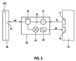
- Fig. 2 shows one for the embodiment of Fig. 1 suitable embodiment of a transmitting and receiving unit 20 in more detail.
- reference numerals designate the same or equivalent elements.
- the transmitting and receiving unit 20 has a generator 21 for generating an RF signal.
- the frequency f of the RF signal can be varied via a control signal V f frequency.
- the frequency determining signal V f is provided by the control output 11 of the controller 10 as an analog or digital signal.
- the transmitting and receiving unit 20 further comprises a circulator 22, which forwards the RF signal of the RF generator 21 via an output to the RF input and output 31 of the distributor 30, from which it is the antenna arrangement 40, not shown here is supplied.
- An RF signal reflected from an object and received via the antenna array 40 and the splitter 30 is returned to the circulator 22 via the same port, which forwards it to a mixer 23.
- the received RF signal with the generator 21 generated and tapped to a tap 24 and the mixer supplied RF signal mixed.
- the resulting mixed signal contains a signal at a lower frequency than the high frequency, which contains information about the relative speed of the reflecting object via the Doppler shift.
- the mixed signal is passed through a low-pass filter 25, which suppresses possibly contained higher-frequency signals, as an intermediate frequency (IF) signal to the IF signal input 12 of the controller 10.
- IF intermediate frequency
- High-frequency signal components in the mixed signal can result, for example, from reflected transmission signals of other transmitting and receiving units 20 which radiate on a different frequency than the transmission and reception unit 20 considered.
- the (low) frequency filtering in the mixed signal corresponds to a frequency selection in the RF signal path of the transmitting and receiving unit 20. In this way, an HF selectivity of the transmitting and receiving unit 20 is achieved, which leads to a directional characteristic for received signals.
- Fig. 3 shows a second embodiment of a radar system with a control device and a radar sensor.
- the structure is analogous to that in Fig. 1 shown embodiment.
- the feed-in point 43r of the antenna arrangement 40 is not terminated with a terminator, but is connected to a further distributor 30, which also allows the connection of transmitting and receiving devices 20.
- indices I (left) and r (right) are used, with all elements provided with the index I pointing to the left feed point 43l and all having the index r provided elements act on the right feed point 43r.
- a number of n transmitting and receiving units 201-1 to 20l-n are provided and a number of m transmitting and receiving devices 20r-1 to 20r-m.
- the distributors 30l and 30r have a corresponding number of RF inputs and outputs 31l-1 to 31l-n and 31r-1 to 31r-m.
- An arrangement as in Fig. 3 can be shown in particular then Advantages are when the total number n + m of the intended transmitting and receiving devices 20 is large and a single distributor 30 with a corresponding number of RF inputs and outputs 31 would have too high a damping.
- the basic operating principle of the arrangement in Fig. 1 and Fig. 3 does not differ, however.
- the transmitting and receiving units 20l and 20r in the embodiment of the Fig. 3 in the Fig. 2 be used in more detail described transmitting and receiving units.
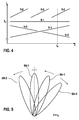
- FIGS. 4 and 5 The following will be related to the FIGS. 4 and 5 the operation of a radar sensor with multiple transmitting and receiving units 20 explained.
- Fig. 4 is a schematic diagram illustrating the frequency f of the emitted RF signals of the transmitting and receiving units as a function of time t in one embodiment of a radar sensor.
- the frequencies f of the transmitting and receiving units 201-1, 20l-2, 20r-1 and 20r-2 are referred to as fl-1, fl-2, fr-1 and fr-2.
- the frequency f 0 marked at the frequency axis indicates the frequency at which the antenna assembly 40 radiates in a direction perpendicular to the direction in which the antenna elements 41 are arranged. This direction is also referred to below as the basic direction.
- the transmitting and receiving unit 201-1 is operated at a constant frequency fl-1 equal to f 0
- the other transmitting and receiving units 20l-2, 20r-1 and 20r-2 are operated with sections linearly changing frequencies.
- the frequency changes are periodic in the example shown, as the sawtooth waveform of the frequency fl-2 can be seen.
- the period length may be selected differently for the various transmitting and receiving units 20. It is also conceivable that one or more of the frequencies are changed depending on a detected object, for example, to keep this in the observation area (object tracking).
- the arrows at the ends of the directional lobes 50 in Fig. 5 symbolize thereby the current direction of movement of the directional lobes 50.
- a relation to the frequency f 0 smaller frequency leads to a tilted right out of the basic direction out directional lobe, whereas a frequency greater than the frequency f 0 leads to a directional leftwave pivoted to the left.
- the overall directivity pattern shown gives consequently as a superposition of the directional lobe 501-1, which is unchanged time aligned with their main beam direction along the primary direction, the directional lobe 50l-2, which is pivoted to the left and continues to move in this direction , the directional lobe 50r-1, which is slightly pivoted to the right and moves to the left, and the directional lobe 50r-2, which is pivoted to the right and continues to pivot in that direction.
- a signal reflected by an object initially only contains information about the speed of the reflecting object.
- information about the signal propagation time is needed, which can be obtained, for example, from pulsed radar signals.
- transit time information can be obtained via frequency modulation (FMCW Frequency Modulated Continuous Wave).
- FMCW Frequency Modulated Continuous Wave In the angle-resolved radar sensors presented in the context of the application, a periodic frequency change used for angular variation can be used simultaneously to obtain distance information from the reflected radar signal win. For this it is necessary to evaluate the received radar signal over at least two periods of the frequency change.
- a further processing of the signals received at the intermediate frequency signal inputs 12 of the control device 10 can advantageously take place via analog / digital converters and subsequent frequency analysis, for example by a fast Fourier transform (FFT).
- FFT fast Fourier transform
- the controller 10 is not part of the radar sensor. However, it may also be implemented as an integral part of the radar sensor.
Landscapes
- Engineering & Computer Science (AREA)
- Radar, Positioning & Navigation (AREA)
- Remote Sensing (AREA)
- Physics & Mathematics (AREA)
- Computer Networks & Wireless Communication (AREA)
- General Physics & Mathematics (AREA)
- Electromagnetism (AREA)
- Computer Security & Cryptography (AREA)
- Radar Systems Or Details Thereof (AREA)
- Variable-Direction Aerials And Aerial Arrays (AREA)
Claims (13)
- Capteur radar, comprenant- un arrangement d'antenne (40) pourvu de plusieurs éléments d'antenne (41) disposés les uns à côté des autres, lesquels sont reliés en série entre eux par des lignes à retard (42), et au moins un point d'alimentation (431, 43r) sur un élément d'antenne (41) extérieur, et- au moins deux unités d'émission et de réception (20), respectivement destinées à générer et à interpréter un signal radar à une fréquence prédéfinie,- les unités d'émission et de réception (20) étant configurées pour le mode de fonctionnement FMCW,- les au moins deux unités d'émission et de réception (20) étant reliées à l'au moins un point d'alimentation (431, 43r) de l'arrangement d'antenne (40) et- les fréquences des signaux radar superposables des au moins deux unités d'émission et de réception (20) pouvant être prédéfinies indépendamment l'une de l'autre.
- Capteur radar selon la revendication 1, avec lequel les au moins deux unités d'émission et de réception (20) sont reliées en permanence à l'arrangement d'antenne (40) par le biais d'un diviseur (30).
- Capteur radar selon la revendication 2, avec lequel le diviseur (30) est un diviseur à haute fréquence de Wilkinson.
- Capteur radar selon la revendication 2, avec lequel le diviseur (30) est un diviseur à haute fréquence hybride.
- Capteur radar selon l'une des revendications 1 à 4, avec lequel l'arrangement d'antenne (40) possède deux points d'alimentation (431, 43r), toutes les unités d'émission et de réception (20) étant reliées à l'un des points d'alimentation (431, 43r) et les autres points d'alimentation (43r, 431) étant terminés par un élément de terminaison (44).
- Capteur radar selon l'une des revendications 1 à 4, avec lequel l'arrangement d'antenne (40) possède deux points d'alimentation (431, 43r) et deux diviseurs (301, 30r), l'un des deux diviseurs (301, 30r) étant relié à l'un des points d'alimentation (431, 43r) et à au moins une unité d'émission et de réception (20).
- Capteur radar selon l'une des revendications 1 à 6, avec lequel les lignes à retard (42) sont conçues de telle sorte qu'un signal radar diffusé par l'arrangement d'antenne (42) est dirigé, la direction du rayonnement principal étant dépendante de la fréquence du signal radar.
- Capteur radar selon l'une des revendications 1 à 7, avec lequel chacune des unités d'émission et de réception (20) possède un générateur de haute fréquence (21) destiné à générer le signal radar, et avec lequel un signal radar reçu est mélangé avec le signal généré par le générateur de haute fréquence (21) en vue de son interprétation.
- Capteur radar selon l'une des revendications 1 à 8, avec lequel une unité d'émission et de réception (20) peut fonctionner avec une fréquence constante.
- Capteur radar selon l'une des revendications 1 à 9, avec lequel le signal radar d'au moins une unité d'émission et de réception (20) est modulé en fréquence en vue de modifier la direction du rayonnement principal et/ou en vue de déterminer la distance.
- Capteur radar selon la revendication 10, avec lequel la modulation de fréquence est une modulation en forme de rampe ou de dents de scie qui sert à modifier la direction du rayonnement principal et à déterminer la distance.
- Capteur radar selon la revendication 10, avec lequel la modulation de fréquence se compose d'une première et d'une deuxième modulation en forme de rampe ou de dents de scie qui se différencient au niveau de leur excursion de fréquence et/ou de leur longueur de période.
- Capteur radar selon l'une des revendications 1 à 12, réalisé sous la forme d'un radar Doppler.
Applications Claiming Priority (2)
| Application Number | Priority Date | Filing Date | Title |
|---|---|---|---|
| DE102010001761A DE102010001761A1 (de) | 2010-02-10 | 2010-02-10 | Radarsensor |
| PCT/EP2010/069578 WO2011098173A1 (fr) | 2010-02-10 | 2010-12-14 | Détecteur radar |
Publications (2)
| Publication Number | Publication Date |
|---|---|
| EP2534730A1 EP2534730A1 (fr) | 2012-12-19 |
| EP2534730B1 true EP2534730B1 (fr) | 2016-09-07 |
Family
ID=43466805
Family Applications (1)
| Application Number | Title | Priority Date | Filing Date |
|---|---|---|---|
| EP10787807.6A Active EP2534730B1 (fr) | 2010-02-10 | 2010-12-14 | Détecteur radar |
Country Status (6)
| Country | Link |
|---|---|
| US (1) | US9190717B2 (fr) |
| EP (1) | EP2534730B1 (fr) |
| JP (1) | JP5763684B2 (fr) |
| CN (1) | CN102754278A (fr) |
| DE (1) | DE102010001761A1 (fr) |
| WO (1) | WO2011098173A1 (fr) |
Families Citing this family (17)
| Publication number | Priority date | Publication date | Assignee | Title |
|---|---|---|---|---|
| JP5682969B2 (ja) * | 2012-04-16 | 2015-03-11 | 日本電信電話株式会社 | アンテナ装置、および電波到来方向推定方法 |
| DE102013203789A1 (de) | 2013-03-06 | 2014-09-11 | Robert Bosch Gmbh | Antennenanordnung mit veränderlicher Richtcharakteristik |
| LU92331B1 (en) * | 2013-12-10 | 2015-06-11 | Iee Sarl | Radar sensor with frequency dependent beam steering |
| DE102014200038A1 (de) * | 2014-01-07 | 2015-07-09 | Siemens Aktiengesellschaft | Antennenanordnung zum Lokalisieren eines bewegten Objektes und Verfahren zum Betreiben einer solchen |
| US9885777B2 (en) * | 2014-01-10 | 2018-02-06 | Raytheon Company | Detection of stealth vehicles using VHF radar |
| EP3097607B1 (fr) * | 2014-01-22 | 2021-02-24 | Evolv Technology, Inc. | Formation de faisceaux avec ouverture diverse en fréquences passives |
| US10437650B2 (en) * | 2014-06-19 | 2019-10-08 | Nec Corporation | Controlling execution of tasks in a series of operational processing by identifying processing units based on task command, task setting information, state of operational processing |
| JP6923799B2 (ja) * | 2017-09-29 | 2021-08-25 | ミツミ電機株式会社 | レーダー装置 |
| DE102017218160B4 (de) | 2017-10-11 | 2024-04-18 | Audi Ag | Verfahren zum Betrieb eines Radarsystems eines Kraftfahrzeugs und Kraftfahrzeug |
| DE102018203464A1 (de) * | 2018-03-08 | 2019-09-12 | Robert Bosch Gmbh | Radarsensorsystem und Verfahren zum Betreiben eines Radarsensorsystems |
| DE102018203934A1 (de) * | 2018-03-15 | 2019-09-19 | Robert Bosch Gmbh | Radarsensorsystem und Verfahren zum Betreiben eines Radarsensorsystems |
| CN110275171B (zh) * | 2018-03-15 | 2021-03-02 | 郑州宇通客车股份有限公司 | 一种车辆雷达探测控制方法及车辆 |
| US10969465B2 (en) * | 2018-05-01 | 2021-04-06 | Mitsubishi Electric Research Laboratories, Inc. | Reference-free nonlinearity correction for FMCW-based sensing systems |
| DE102018118863A1 (de) | 2018-08-02 | 2020-02-06 | Infineon Technologies Ag | Radarvorrichtung und Verfahren zum Erzeugen unterschiedlicher Richtcharakteristika |
| DE102018214586A1 (de) * | 2018-08-29 | 2020-03-05 | Robert Bosch Gmbh | Vorrichtung zum Empfangen von Licht zur Detektion eines Objekts |
| US11309636B2 (en) * | 2019-12-18 | 2022-04-19 | Waymo Llc | Antenna structure for reducing beam squint and sidelobes |
| CN113628356A (zh) * | 2021-06-02 | 2021-11-09 | 中创未来智能技术(南京)研究院有限公司 | 一种高速公路用etc收费运维系统及方法 |
Family Cites Families (31)
| Publication number | Priority date | Publication date | Assignee | Title |
|---|---|---|---|---|
| US2810905A (en) * | 1949-08-23 | 1957-10-22 | Sperry Rand Corp | High frequency directive beam apparatus |
| US3179937A (en) * | 1960-06-21 | 1965-04-20 | Frank R Abbott | Two-dimensional electromagnetic delay line |
| US3274601A (en) * | 1962-12-12 | 1966-09-20 | Blass Antenna Electronics Corp | Antenna system with electronic scanning means |
| US3400405A (en) * | 1964-06-01 | 1968-09-03 | Sylvania Electric Prod | Phased array system |
| US3419870A (en) * | 1965-05-24 | 1968-12-31 | North American Rockwell | Dual-plane frequency-scanned antenna array |
| US3434139A (en) * | 1965-07-15 | 1969-03-18 | North American Rockwell | Frequency-controlled scanning monopulse antenna |
| US3480961A (en) * | 1968-02-02 | 1969-11-25 | Univ Ohio State Res Found | Surface-wave antenna having discontinuous coaxial line |
| US4119971A (en) * | 1977-02-04 | 1978-10-10 | Hughes Aircraft Company | High data rate frequency scan slotted waveguide antenna |
| JPS53114282A (en) * | 1977-03-16 | 1978-10-05 | Tokyo Shibaura Electric Co | Ultrasonic diagnosing device |
| US4276551A (en) * | 1979-06-01 | 1981-06-30 | Hughes Aircraft Company | Electronically scanned antenna |
| US4403220A (en) * | 1980-02-05 | 1983-09-06 | Donovan John S | Radar system for collision avoidance |
| CA1234903A (fr) | 1987-07-16 | 1988-04-05 | Anthony R. Raab | Systeme radar a balayage electronique |
| CA1234911A (fr) | 1987-07-16 | 1988-04-05 | Anthony R. Raab | Radiometre a balayage de frequences |
| US5063390A (en) * | 1991-02-19 | 1991-11-05 | The United States Of America As Represented By The Secretary Of The Army | Non-dispersive acoustic transport time delay beam steering antenna |
| US5150336A (en) * | 1991-09-03 | 1992-09-22 | The United States Of America As Represented By The Secretary Of The Navy | Frequency dispersive transmitting array |
| JP3212789B2 (ja) * | 1993-12-29 | 2001-09-25 | 株式会社東芝 | ビーム走査アンテナ |
| GB9401361D0 (en) * | 1994-01-25 | 1994-03-23 | Philips Electronics Uk Ltd | A radar system |
| JPH11308046A (ja) * | 1998-04-21 | 1999-11-05 | Mitsubishi Electric Corp | アンテナ装置 |
| JP3456167B2 (ja) * | 1999-06-24 | 2003-10-14 | 三菱電機株式会社 | 多機能アンテナ装置 |
| USH2028H1 (en) * | 1999-07-22 | 2002-06-04 | United States Of America | Frequency-scan traveling wave antenna |
| US6266011B1 (en) * | 1999-09-30 | 2001-07-24 | Rockwell Science Center, Llc | Electronically scanned phased array antenna system and method with scan control independent of radiating frequency |
| US6806845B2 (en) * | 2003-01-14 | 2004-10-19 | Honeywell Federal Manufacturing & Technologies, Llc | Time-delayed directional beam phased array antenna |
| US7061443B2 (en) * | 2004-04-01 | 2006-06-13 | Raytheon Company | MMW electronically scanned antenna |
| DE112005003573T5 (de) * | 2005-05-09 | 2008-03-27 | Elta Systems Ltd. | Phased-Array-Radarantenne, welche eine verminderte Suchzeit hat, und Verfahren zur Benutzung derselben |
| US7791530B2 (en) * | 2006-01-05 | 2010-09-07 | Autoliv Asp, Inc. | Time duplex apparatus and method for radar sensor front-ends |
| JP2007251589A (ja) * | 2006-03-16 | 2007-09-27 | Murata Mfg Co Ltd | アレイアンテナ装置及びrfidシステム |
| DE102006032540A1 (de) | 2006-07-13 | 2008-01-17 | Robert Bosch Gmbh | Winkelauflösender Radarsensor |
| JP2008051560A (ja) * | 2006-08-22 | 2008-03-06 | Denso Corp | レーダ装置 |
| JP2008261794A (ja) * | 2007-04-13 | 2008-10-30 | Mitsubishi Electric Corp | レーダ装置 |
| JP4521440B2 (ja) * | 2007-12-18 | 2010-08-11 | 株式会社東芝 | アレイアンテナ装置及びその送受信モジュール |
| CN101609931B (zh) * | 2008-06-20 | 2012-12-05 | 电子科技大学 | 基于时间调制的天线阵列相位控制技术及其系统实现 |
-
2010
- 2010-02-10 DE DE102010001761A patent/DE102010001761A1/de not_active Withdrawn
- 2010-12-14 EP EP10787807.6A patent/EP2534730B1/fr active Active
- 2010-12-14 CN CN2010800636587A patent/CN102754278A/zh active Pending
- 2010-12-14 US US13/519,567 patent/US9190717B2/en active Active
- 2010-12-14 JP JP2012552278A patent/JP5763684B2/ja active Active
- 2010-12-14 WO PCT/EP2010/069578 patent/WO2011098173A1/fr active Application Filing
Also Published As
| Publication number | Publication date |
|---|---|
| DE102010001761A1 (de) | 2011-08-11 |
| US20130016001A1 (en) | 2013-01-17 |
| US9190717B2 (en) | 2015-11-17 |
| WO2011098173A1 (fr) | 2011-08-18 |
| CN102754278A (zh) | 2012-10-24 |
| EP2534730A1 (fr) | 2012-12-19 |
| JP5763684B2 (ja) | 2015-08-12 |
| JP2013519096A (ja) | 2013-05-23 |
Similar Documents
| Publication | Publication Date | Title |
|---|---|---|
| EP2534730B1 (fr) | Détecteur radar | |
| DE112011102901B4 (de) | Mehrbereich-Radarsystem | |
| DE19648203C2 (de) | Mehrstrahliges Kraftfahrzeug-Radarsystem | |
| EP1792203B1 (fr) | Capteur radar multifaisceaux planaire monostatique | |
| EP3204788B1 (fr) | Capteur radar formeur d'image avec formation numérique horizontale de faisceau et mesure verticale d'objet par comparaison de phases en cas d'émetteurs décalés les uns par rapport aux autres | |
| EP2756329B1 (fr) | Capteur de radar imageur à lobe d'antenne étroit et zone de détection angulaire large | |
| DE602004002145T2 (de) | Radaranordnung mit Schaltermatrix zur adaptiven Strahlformung im Empfangszweig und Umschalten des Sendezweigs | |
| DE102016102241A1 (de) | Auf digitaler strahlformung basierendes auflösen von nicht-im-weg-zielen, die aufgrund von gitterkeulen in array-antennen-radars als im-weg-ziele erscheinen | |
| EP1570296B1 (fr) | Dispositif de mesure de positions angulaires | |
| DE102004059915A1 (de) | Radarsystem | |
| DE19714570A1 (de) | Mehrstahliges Radarsystem | |
| EP2769236B1 (fr) | Capteur radar à résolution angulaire | |
| WO2012034736A1 (fr) | Capteur radar pour véhicules à moteur, notamment capteur lca | |
| WO2006066781A2 (fr) | Systeme radar d'un vehicule automobile et procede d'evaluation | |
| DE102009027003A1 (de) | Optimierung der Schaltreihenfolge bei geschalteten Antennenarrays | |
| EP2616839B1 (fr) | Capteur radar pour véhicules à moteur, notamment capteur rca | |
| WO2007077062A1 (fr) | Dispositif radar | |
| EP2722686A1 (fr) | Système SAR interférométrique | |
| WO2004046752A1 (fr) | Procede et dispositif pour etablir une image radar au moyen d'un radar a ondes entretenues et modulation de frequence | |
| EP2225582B1 (fr) | Détecteur radar monostatique multifaisceau, et procédé | |
| WO2008043595A1 (fr) | Radar détecteur à résolution angulaire pour automobiles | |
| DE102007058236A1 (de) | Bistatische Arrayantenne sowie Verfahren | |
| DE102010041755A1 (de) | Radarsystem | |
| DE102004045108A1 (de) | Empfangssystem für die Bestimmung eines Ziel-Ablagewinkels | |
| DE102016206787A1 (de) | Radarsensor für Kraftfahrzeuge |
Legal Events
| Date | Code | Title | Description |
|---|---|---|---|
| PUAI | Public reference made under article 153(3) epc to a published international application that has entered the european phase |
Free format text: ORIGINAL CODE: 0009012 |
|
| 17P | Request for examination filed |
Effective date: 20120910 |
|
| AK | Designated contracting states |
Kind code of ref document: A1 Designated state(s): AL AT BE BG CH CY CZ DE DK EE ES FI FR GB GR HR HU IE IS IT LI LT LU LV MC MK MT NL NO PL PT RO RS SE SI SK SM TR |
|
| DAX | Request for extension of the european patent (deleted) | ||
| GRAP | Despatch of communication of intention to grant a patent |
Free format text: ORIGINAL CODE: EPIDOSNIGR1 |
|
| RIC1 | Information provided on ipc code assigned before grant |
Ipc: G01S 13/93 20060101ALI20160519BHEP Ipc: G01S 7/03 20060101ALI20160519BHEP Ipc: H01Q 25/00 20060101ALI20160519BHEP Ipc: H01Q 21/08 20060101ALI20160519BHEP Ipc: H01Q 3/22 20060101AFI20160519BHEP Ipc: H01Q 1/32 20060101ALI20160519BHEP Ipc: G01S 13/42 20060101ALI20160519BHEP Ipc: G01S 13/34 20060101ALI20160519BHEP |
|
| INTG | Intention to grant announced |
Effective date: 20160615 |
|
| GRAS | Grant fee paid |
Free format text: ORIGINAL CODE: EPIDOSNIGR3 |
|
| GRAA | (expected) grant |
Free format text: ORIGINAL CODE: 0009210 |
|
| AK | Designated contracting states |
Kind code of ref document: B1 Designated state(s): AL AT BE BG CH CY CZ DE DK EE ES FI FR GB GR HR HU IE IS IT LI LT LU LV MC MK MT NL NO PL PT RO RS SE SI SK SM TR |
|
| REG | Reference to a national code |
Ref country code: GB Ref legal event code: FG4D Free format text: NOT ENGLISH |
|
| REG | Reference to a national code |
Ref country code: CH Ref legal event code: EP |
|
| REG | Reference to a national code |
Ref country code: IE Ref legal event code: FG4D Free format text: LANGUAGE OF EP DOCUMENT: GERMAN |
|
| REG | Reference to a national code |
Ref country code: AT Ref legal event code: REF Ref document number: 827585 Country of ref document: AT Kind code of ref document: T Effective date: 20161015 |
|
| REG | Reference to a national code |
Ref country code: DE Ref legal event code: R096 Ref document number: 502010012376 Country of ref document: DE |
|
| REG | Reference to a national code |
Ref country code: FR Ref legal event code: PLFP Year of fee payment: 7 |
|
| REG | Reference to a national code |
Ref country code: LT Ref legal event code: MG4D |
|
| REG | Reference to a national code |
Ref country code: NL Ref legal event code: MP Effective date: 20160907 |
|
| PG25 | Lapsed in a contracting state [announced via postgrant information from national office to epo] |
Ref country code: FI Free format text: LAPSE BECAUSE OF FAILURE TO SUBMIT A TRANSLATION OF THE DESCRIPTION OR TO PAY THE FEE WITHIN THE PRESCRIBED TIME-LIMIT Effective date: 20160907 Ref country code: LT Free format text: LAPSE BECAUSE OF FAILURE TO SUBMIT A TRANSLATION OF THE DESCRIPTION OR TO PAY THE FEE WITHIN THE PRESCRIBED TIME-LIMIT Effective date: 20160907 Ref country code: RS Free format text: LAPSE BECAUSE OF FAILURE TO SUBMIT A TRANSLATION OF THE DESCRIPTION OR TO PAY THE FEE WITHIN THE PRESCRIBED TIME-LIMIT Effective date: 20160907 Ref country code: HR Free format text: LAPSE BECAUSE OF FAILURE TO SUBMIT A TRANSLATION OF THE DESCRIPTION OR TO PAY THE FEE WITHIN THE PRESCRIBED TIME-LIMIT Effective date: 20160907 Ref country code: NO Free format text: LAPSE BECAUSE OF FAILURE TO SUBMIT A TRANSLATION OF THE DESCRIPTION OR TO PAY THE FEE WITHIN THE PRESCRIBED TIME-LIMIT Effective date: 20161207 |
|
| PG25 | Lapsed in a contracting state [announced via postgrant information from national office to epo] |
Ref country code: GR Free format text: LAPSE BECAUSE OF FAILURE TO SUBMIT A TRANSLATION OF THE DESCRIPTION OR TO PAY THE FEE WITHIN THE PRESCRIBED TIME-LIMIT Effective date: 20161208 Ref country code: NL Free format text: LAPSE BECAUSE OF FAILURE TO SUBMIT A TRANSLATION OF THE DESCRIPTION OR TO PAY THE FEE WITHIN THE PRESCRIBED TIME-LIMIT Effective date: 20160907 Ref country code: LV Free format text: LAPSE BECAUSE OF FAILURE TO SUBMIT A TRANSLATION OF THE DESCRIPTION OR TO PAY THE FEE WITHIN THE PRESCRIBED TIME-LIMIT Effective date: 20160907 Ref country code: ES Free format text: LAPSE BECAUSE OF FAILURE TO SUBMIT A TRANSLATION OF THE DESCRIPTION OR TO PAY THE FEE WITHIN THE PRESCRIBED TIME-LIMIT Effective date: 20160907 Ref country code: SE Free format text: LAPSE BECAUSE OF FAILURE TO SUBMIT A TRANSLATION OF THE DESCRIPTION OR TO PAY THE FEE WITHIN THE PRESCRIBED TIME-LIMIT Effective date: 20160907 |
|
| PG25 | Lapsed in a contracting state [announced via postgrant information from national office to epo] |
Ref country code: RO Free format text: LAPSE BECAUSE OF FAILURE TO SUBMIT A TRANSLATION OF THE DESCRIPTION OR TO PAY THE FEE WITHIN THE PRESCRIBED TIME-LIMIT Effective date: 20160907 Ref country code: EE Free format text: LAPSE BECAUSE OF FAILURE TO SUBMIT A TRANSLATION OF THE DESCRIPTION OR TO PAY THE FEE WITHIN THE PRESCRIBED TIME-LIMIT Effective date: 20160907 |
|
| PG25 | Lapsed in a contracting state [announced via postgrant information from national office to epo] |
Ref country code: SK Free format text: LAPSE BECAUSE OF FAILURE TO SUBMIT A TRANSLATION OF THE DESCRIPTION OR TO PAY THE FEE WITHIN THE PRESCRIBED TIME-LIMIT Effective date: 20160907 Ref country code: PT Free format text: LAPSE BECAUSE OF FAILURE TO SUBMIT A TRANSLATION OF THE DESCRIPTION OR TO PAY THE FEE WITHIN THE PRESCRIBED TIME-LIMIT Effective date: 20170109 Ref country code: BG Free format text: LAPSE BECAUSE OF FAILURE TO SUBMIT A TRANSLATION OF THE DESCRIPTION OR TO PAY THE FEE WITHIN THE PRESCRIBED TIME-LIMIT Effective date: 20161207 Ref country code: BE Free format text: LAPSE BECAUSE OF NON-PAYMENT OF DUE FEES Effective date: 20161231 Ref country code: CZ Free format text: LAPSE BECAUSE OF FAILURE TO SUBMIT A TRANSLATION OF THE DESCRIPTION OR TO PAY THE FEE WITHIN THE PRESCRIBED TIME-LIMIT Effective date: 20160907 Ref country code: SM Free format text: LAPSE BECAUSE OF FAILURE TO SUBMIT A TRANSLATION OF THE DESCRIPTION OR TO PAY THE FEE WITHIN THE PRESCRIBED TIME-LIMIT Effective date: 20160907 Ref country code: PL Free format text: LAPSE BECAUSE OF FAILURE TO SUBMIT A TRANSLATION OF THE DESCRIPTION OR TO PAY THE FEE WITHIN THE PRESCRIBED TIME-LIMIT Effective date: 20160907 Ref country code: IS Free format text: LAPSE BECAUSE OF FAILURE TO SUBMIT A TRANSLATION OF THE DESCRIPTION OR TO PAY THE FEE WITHIN THE PRESCRIBED TIME-LIMIT Effective date: 20170107 |
|
| REG | Reference to a national code |
Ref country code: DE Ref legal event code: R097 Ref document number: 502010012376 Country of ref document: DE |
|
| PG25 | Lapsed in a contracting state [announced via postgrant information from national office to epo] |
Ref country code: IT Free format text: LAPSE BECAUSE OF FAILURE TO SUBMIT A TRANSLATION OF THE DESCRIPTION OR TO PAY THE FEE WITHIN THE PRESCRIBED TIME-LIMIT Effective date: 20160907 |
|
| PLBE | No opposition filed within time limit |
Free format text: ORIGINAL CODE: 0009261 |
|
| STAA | Information on the status of an ep patent application or granted ep patent |
Free format text: STATUS: NO OPPOSITION FILED WITHIN TIME LIMIT |
|
| PG25 | Lapsed in a contracting state [announced via postgrant information from national office to epo] |
Ref country code: DK Free format text: LAPSE BECAUSE OF FAILURE TO SUBMIT A TRANSLATION OF THE DESCRIPTION OR TO PAY THE FEE WITHIN THE PRESCRIBED TIME-LIMIT Effective date: 20160907 |
|
| REG | Reference to a national code |
Ref country code: CH Ref legal event code: PL |
|
| 26N | No opposition filed |
Effective date: 20170608 |
|
| PG25 | Lapsed in a contracting state [announced via postgrant information from national office to epo] |
Ref country code: SI Free format text: LAPSE BECAUSE OF FAILURE TO SUBMIT A TRANSLATION OF THE DESCRIPTION OR TO PAY THE FEE WITHIN THE PRESCRIBED TIME-LIMIT Effective date: 20160907 |
|
| PG25 | Lapsed in a contracting state [announced via postgrant information from national office to epo] |
Ref country code: MC Free format text: LAPSE BECAUSE OF FAILURE TO SUBMIT A TRANSLATION OF THE DESCRIPTION OR TO PAY THE FEE WITHIN THE PRESCRIBED TIME-LIMIT Effective date: 20160907 |
|
| REG | Reference to a national code |
Ref country code: IE Ref legal event code: MM4A |
|
| PG25 | Lapsed in a contracting state [announced via postgrant information from national office to epo] |
Ref country code: CH Free format text: LAPSE BECAUSE OF NON-PAYMENT OF DUE FEES Effective date: 20161231 Ref country code: LU Free format text: LAPSE BECAUSE OF NON-PAYMENT OF DUE FEES Effective date: 20161214 Ref country code: LI Free format text: LAPSE BECAUSE OF NON-PAYMENT OF DUE FEES Effective date: 20161231 |
|
| PG25 | Lapsed in a contracting state [announced via postgrant information from national office to epo] |
Ref country code: IE Free format text: LAPSE BECAUSE OF NON-PAYMENT OF DUE FEES Effective date: 20161214 |
|
| REG | Reference to a national code |
Ref country code: FR Ref legal event code: PLFP Year of fee payment: 8 |
|
| REG | Reference to a national code |
Ref country code: BE Ref legal event code: MM Effective date: 20161231 |
|
| REG | Reference to a national code |
Ref country code: AT Ref legal event code: MM01 Ref document number: 827585 Country of ref document: AT Kind code of ref document: T Effective date: 20161214 |
|
| PG25 | Lapsed in a contracting state [announced via postgrant information from national office to epo] |
Ref country code: AT Free format text: LAPSE BECAUSE OF NON-PAYMENT OF DUE FEES Effective date: 20161214 Ref country code: CY Free format text: LAPSE BECAUSE OF FAILURE TO SUBMIT A TRANSLATION OF THE DESCRIPTION OR TO PAY THE FEE WITHIN THE PRESCRIBED TIME-LIMIT Effective date: 20160907 Ref country code: HU Free format text: LAPSE BECAUSE OF FAILURE TO SUBMIT A TRANSLATION OF THE DESCRIPTION OR TO PAY THE FEE WITHIN THE PRESCRIBED TIME-LIMIT; INVALID AB INITIO Effective date: 20101214 |
|
| PG25 | Lapsed in a contracting state [announced via postgrant information from national office to epo] |
Ref country code: MK Free format text: LAPSE BECAUSE OF FAILURE TO SUBMIT A TRANSLATION OF THE DESCRIPTION OR TO PAY THE FEE WITHIN THE PRESCRIBED TIME-LIMIT Effective date: 20160907 Ref country code: TR Free format text: LAPSE BECAUSE OF FAILURE TO SUBMIT A TRANSLATION OF THE DESCRIPTION OR TO PAY THE FEE WITHIN THE PRESCRIBED TIME-LIMIT Effective date: 20160907 |
|
| PG25 | Lapsed in a contracting state [announced via postgrant information from national office to epo] |
Ref country code: MT Free format text: LAPSE BECAUSE OF FAILURE TO SUBMIT A TRANSLATION OF THE DESCRIPTION OR TO PAY THE FEE WITHIN THE PRESCRIBED TIME-LIMIT Effective date: 20160907 |
|
| PG25 | Lapsed in a contracting state [announced via postgrant information from national office to epo] |
Ref country code: AL Free format text: LAPSE BECAUSE OF FAILURE TO SUBMIT A TRANSLATION OF THE DESCRIPTION OR TO PAY THE FEE WITHIN THE PRESCRIBED TIME-LIMIT Effective date: 20160907 |
|
| PGFP | Annual fee paid to national office [announced via postgrant information from national office to epo] |
Ref country code: GB Payment date: 20201222 Year of fee payment: 11 Ref country code: FR Payment date: 20201218 Year of fee payment: 11 |
|
| GBPC | Gb: european patent ceased through non-payment of renewal fee |
Effective date: 20211214 |
|
| PG25 | Lapsed in a contracting state [announced via postgrant information from national office to epo] |
Ref country code: GB Free format text: LAPSE BECAUSE OF NON-PAYMENT OF DUE FEES Effective date: 20211214 |
|
| PG25 | Lapsed in a contracting state [announced via postgrant information from national office to epo] |
Ref country code: FR Free format text: LAPSE BECAUSE OF NON-PAYMENT OF DUE FEES Effective date: 20211231 |
|
| REG | Reference to a national code |
Ref country code: DE Ref legal event code: R084 Ref document number: 502010012376 Country of ref document: DE |
|
| PGFP | Annual fee paid to national office [announced via postgrant information from national office to epo] |
Ref country code: DE Payment date: 20240227 Year of fee payment: 14 |