EP1570296B1 - Dispositif de mesure de positions angulaires - Google Patents
Dispositif de mesure de positions angulaires Download PDFInfo
- Publication number
- EP1570296B1 EP1570296B1 EP03753311A EP03753311A EP1570296B1 EP 1570296 B1 EP1570296 B1 EP 1570296B1 EP 03753311 A EP03753311 A EP 03753311A EP 03753311 A EP03753311 A EP 03753311A EP 1570296 B1 EP1570296 B1 EP 1570296B1
- Authority
- EP
- European Patent Office
- Prior art keywords
- phase shifter
- antenna elements
- phase
- antenna
- evaluation
- Prior art date
- Legal status (The legal status is an assumption and is not a legal conclusion. Google has not performed a legal analysis and makes no representation as to the accuracy of the status listed.)
- Expired - Lifetime
Links
- 238000011156 evaluation Methods 0.000 claims abstract description 11
- 238000005259 measurement Methods 0.000 claims description 6
- 230000005855 radiation Effects 0.000 claims description 4
- 238000013459 approach Methods 0.000 description 6
- 238000006243 chemical reaction Methods 0.000 description 3
- 238000013461 design Methods 0.000 description 3
- 238000012545 processing Methods 0.000 description 3
- 238000001514 detection method Methods 0.000 description 2
- 238000010586 diagram Methods 0.000 description 2
- 238000000034 method Methods 0.000 description 2
- 238000012544 monitoring process Methods 0.000 description 2
- 230000004888 barrier function Effects 0.000 description 1
- 230000015572 biosynthetic process Effects 0.000 description 1
- 239000012141 concentrate Substances 0.000 description 1
- 238000012937 correction Methods 0.000 description 1
- 230000001419 dependent effect Effects 0.000 description 1
- 230000001066 destructive effect Effects 0.000 description 1
- 238000011161 development Methods 0.000 description 1
- 238000000605 extraction Methods 0.000 description 1
- 238000001914 filtration Methods 0.000 description 1
- 230000010354 integration Effects 0.000 description 1
- 239000000203 mixture Substances 0.000 description 1
- 230000010355 oscillation Effects 0.000 description 1
- 230000001151 other effect Effects 0.000 description 1
- 230000010363 phase shift Effects 0.000 description 1
- 230000001629 suppression Effects 0.000 description 1
- 230000002123 temporal effect Effects 0.000 description 1
Images


Classifications
-
- G—PHYSICS
- G01—MEASURING; TESTING
- G01S—RADIO DIRECTION-FINDING; RADIO NAVIGATION; DETERMINING DISTANCE OR VELOCITY BY USE OF RADIO WAVES; LOCATING OR PRESENCE-DETECTING BY USE OF THE REFLECTION OR RERADIATION OF RADIO WAVES; ANALOGOUS ARRANGEMENTS USING OTHER WAVES
- G01S13/00—Systems using the reflection or reradiation of radio waves, e.g. radar systems; Analogous systems using reflection or reradiation of waves whose nature or wavelength is irrelevant or unspecified
- G01S13/02—Systems using reflection of radio waves, e.g. primary radar systems; Analogous systems
- G01S13/06—Systems determining position data of a target
- G01S13/42—Simultaneous measurement of distance and other co-ordinates
- G01S13/44—Monopulse radar, i.e. simultaneous lobing
- G01S13/4463—Monopulse radar, i.e. simultaneous lobing using phased arrays
-
- G—PHYSICS
- G01—MEASURING; TESTING
- G01S—RADIO DIRECTION-FINDING; RADIO NAVIGATION; DETERMINING DISTANCE OR VELOCITY BY USE OF RADIO WAVES; LOCATING OR PRESENCE-DETECTING BY USE OF THE REFLECTION OR RERADIATION OF RADIO WAVES; ANALOGOUS ARRANGEMENTS USING OTHER WAVES
- G01S7/00—Details of systems according to groups G01S13/00, G01S15/00, G01S17/00
- G01S7/02—Details of systems according to groups G01S13/00, G01S15/00, G01S17/00 of systems according to group G01S13/00
- G01S7/03—Details of HF subsystems specially adapted therefor, e.g. common to transmitter and receiver
- G01S7/032—Constructional details for solid-state radar subsystems
-
- G—PHYSICS
- G01—MEASURING; TESTING
- G01S—RADIO DIRECTION-FINDING; RADIO NAVIGATION; DETERMINING DISTANCE OR VELOCITY BY USE OF RADIO WAVES; LOCATING OR PRESENCE-DETECTING BY USE OF THE REFLECTION OR RERADIATION OF RADIO WAVES; ANALOGOUS ARRANGEMENTS USING OTHER WAVES
- G01S13/00—Systems using the reflection or reradiation of radio waves, e.g. radar systems; Analogous systems using reflection or reradiation of waves whose nature or wavelength is irrelevant or unspecified
- G01S13/02—Systems using reflection of radio waves, e.g. primary radar systems; Analogous systems
- G01S13/06—Systems determining position data of a target
- G01S13/42—Simultaneous measurement of distance and other co-ordinates
- G01S13/426—Scanning radar, e.g. 3D radar
-
- G—PHYSICS
- G01—MEASURING; TESTING
- G01S—RADIO DIRECTION-FINDING; RADIO NAVIGATION; DETERMINING DISTANCE OR VELOCITY BY USE OF RADIO WAVES; LOCATING OR PRESENCE-DETECTING BY USE OF THE REFLECTION OR RERADIATION OF RADIO WAVES; ANALOGOUS ARRANGEMENTS USING OTHER WAVES
- G01S13/00—Systems using the reflection or reradiation of radio waves, e.g. radar systems; Analogous systems using reflection or reradiation of waves whose nature or wavelength is irrelevant or unspecified
- G01S13/02—Systems using reflection of radio waves, e.g. primary radar systems; Analogous systems
- G01S13/06—Systems determining position data of a target
- G01S13/42—Simultaneous measurement of distance and other co-ordinates
- G01S13/44—Monopulse radar, i.e. simultaneous lobing
- G01S13/4409—HF sub-systems particularly adapted therefor, e.g. circuits for signal combination
-
- G—PHYSICS
- G01—MEASURING; TESTING
- G01S—RADIO DIRECTION-FINDING; RADIO NAVIGATION; DETERMINING DISTANCE OR VELOCITY BY USE OF RADIO WAVES; LOCATING OR PRESENCE-DETECTING BY USE OF THE REFLECTION OR RERADIATION OF RADIO WAVES; ANALOGOUS ARRANGEMENTS USING OTHER WAVES
- G01S13/00—Systems using the reflection or reradiation of radio waves, e.g. radar systems; Analogous systems using reflection or reradiation of waves whose nature or wavelength is irrelevant or unspecified
- G01S13/02—Systems using reflection of radio waves, e.g. primary radar systems; Analogous systems
- G01S13/06—Systems determining position data of a target
- G01S13/46—Indirect determination of position data
- G01S2013/468—Indirect determination of position data by Triangulation, i.e. two antennas or two sensors determine separately the bearing, direction or angle to a target, whereby with the knowledge of the baseline length, the position data of the target is determined
Definitions
- the invention relates to a device for measuring angular positions using radar pulses with mutually overlapping beam characteristics of at least two antenna elements, according to the preamble of claim 1, as shown in US 5,017,927 known.
- Radar sensors for detecting the nearby automotive environment are provided for functions such as reversing aid, parking aid, parking space measurement, blind spot monitoring, slow follow-up driving or precrash detection.
- the information about their angular position retative to the vehicle is important to assess the relevance of detected objects for each function.
- the prior art is to calculate the angular direction of objects via the so-called trilateration.
- the distance information of several adjacent sensors are used to determine by means of simple trigonometric conversions and the angular storage of targets.
- a disadvantage of this method is that always several sensors are required at a certain distance, even to learn the position of only one target. Also, these sensors must each capture one and the same target in order to avoid misjudgements.
- a monopulse phase array antenna system is known with transmit and receive modules controlled by a beam sweep controller become. From the received signals from the various antenna elements, sum signals and angle difference signals are derived. Each of the transmit and receive modules is equipped with two 180 ° phase shifters to determine the angular difference signals. For independent target tracking in azimuth and elevation direction, it is known to evaluate a sum signal and two differential signals.
- a reversing aid can be equipped with only one angle-measuring SRR sensor, whereas conventional systems require three sensors.
- only one to two sensors would be required with the implementation according to the invention instead of three or four sensors as in conventional systems.
- one sensor is sufficient instead of the usual two sensors.
- the known radar monopulse technique is used for the angle measurement, in which on the comparison of received signals in different, mutually overlapping beam lobes and knowledge of the radiation characteristics itself information about the angular deviation is derivable (comparable to a so-called "best fit matching "of the received signals).
- This evaluation method is very similar to what is also used in long range radar (LRR, ACC). When LRR radar three or four receive lobes are formed and their mutual overlap used for angle estimation by comparing the received signals.
- two different reception characteristics are generated with the widest possible overlapping area.
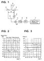
- at least two antenna elements 1 and 2 each with adjustable vibration phases used.
- the different phase states are generated by an intermediate HF component, in the example according to FIG. 1 this is a switchable phase shifter 3, which is interposed in one of the two antenna paths shown here.
- the oscillation phase of the antenna element 2 is set different from that of the antenna element 1, whereby the directional characteristic of the overall arrangement is significantly influenced.
- the signals of both antenna elements 1 and 2 are subsequently combined additively in the reception path (summing node 8) and a mixer unit 4 (Mixing with a local oscillator signal, LO) and further processing (filtering 5, analog / digital conversion (ADC) 6, evaluation 7) supplied.
- FIG. 2 shows for a simple model of a patch antenna (for other antenna element characteristics slightly different beam characteristics), the amplitude characteristics of the overall arrangement for both switching states of the phase shifter 3.
- the switching period should not be too low, since otherwise the very cost-effective approach of direct mixing of the RF carrier signal in the LF baseband (so-called homodyne approach, baseband frequency components in the kHz range) would have to be modified accordingly.
- the relative movements of targets or sensor carrier (ego vehicle) must be negligible or compensated in the evaluation (target angle estimation) (determining the upper limit of the switching period, but on the other hand, a homodyne approach (determining the With HF carrier frequencies in the GHz range, switching periods in the range of a few ⁇ s, for example 5 to 50 ⁇ s, are advantageous.
- the angle of the target is obtained by comparing the relative amplitude and phase change in the reception path in both switching states with the two complex-valued directional characteristics of the antenna arrangement (sum and) difference Beam).
- the distance d of both antenna elements - see FIG. 1 - In the range of half the wavelength is, for example, at 24 GHz about 6.5 mm.
- FIG. 4 shows an embodiment, wherein the two antenna elements 1 and 2 are formed here by way of example by four individual radiators. These have the task of vertical arrangement to the road surface after obstruction in the vehicle to bundle the energy in the vertical direction (elevation bundling) in order to obtain a corresponding range here but also to get not too strong reflections from the road itself.
- elevation bundling energy in the vertical direction
- azimuth there is only a small bundling per column, so that the directional diagrams in the azimuth are similar to those in FIG. 2 are very wide, in order to have the largest possible horizontal detection range and especially here the widest possible overlap of both directional diagrams.
- the outlined bushings 9 in FIG. 4 have the task to concentrate the RF components that require a component assembly, such as the 180 ° phase shifter 3, in the plane or on the layer, where even more equipment is required (mixer 4, etc.), so that a double-sided Assembly is avoided.
- the filter 5 is in This embodiment is a low-pass filter TP, if the radar sensor principle is based homodyner approach, that is both sent with an oscillator, not shown here, as well as the received signal is mixed directly into the baseband (direct conversion). Other embodiments are also possible, for example heterodyne approach with mixture in an intermediate frequency level via another oscillator, filter design then as a bandpass.
- FIG. 5a shows yet another way, as the angle determination of the type described above is possible.
- the phase-adjusting element used here is a so-called 180 ° hybrid 10, called Ratrace in the literature. This has the property of dividing a signal incident on a gate equally to the gates opposite here and with a relative phase difference of 180 °, while the fourth gate is insulated. Due to the reciprocity and linearity of this component, it is equally possible to apply two signals to two input ports and to subtract the sum and the difference signal at the two (here) opposite ports, in this case the sum beam and difference beam.
- An advantage of this approach is that both beams are present at the same time, so that the negative influence of target fluctuation or relative movements does not occur here.
- the disadvantage is that both gates for further processing each require their own mixer, filter and AD converter (hardware costs).
- the two gates of the ratrace can also be fed via a suitable changeover switch 11 to a mixer in time division multiplex ( FIG. 5b ).
- FIGS. 6 and 7 still show versions with two columns per antenna element.
- By implementing more than one antenna column per antenna element it is possible to obtain a bundling of the reception energy in a horizontal plane. As a result, a larger antenna gain and thus a greater radar range can be achieved, while the overlap area of the sum and difference beam is thereby narrowed.
- This can be advantageous for functions such as a reversing aid.
- this embodiment may be advantageous for certain functions in which a certain suppression of signals (interferers) in the side area is just desired, for example, from crash barriers or other development on the roadside. This is directly supported by the strong bundling of multi-column antenna elements.
- the phase shifter 3 can be advantageously designed as a PIN diode phase shifter.
- a radar sensor may comprise, in a high integration design, the phase shifter or, if necessary, the switch, signal combining (T-branch, Wilkinson divider, or the like), the mixer and optionally additional low noise preamplifiers (LNAs) in a monolithic microwave integrated (MMIC) circiut).
- the phase shifter or, if necessary, the switch, signal combining (T-branch, Wilkinson divider, or the like), the mixer and optionally additional low noise preamplifiers (LNAs) in a monolithic microwave integrated (MMIC) circiut).
- MMIC monolithic microwave integrated
- phase shifter 3 an RF MEMS 180 ° phase shifter (RF: Radio Frequency, MEMS: Microelectromechanical System) can also be used.
- RF Radio Frequency
- MEMS Microelectromechanical System
- the antenna element may be provided in different designs: individual radiators, columns, several columns together per antenna element, so-called patch radiators, etc.
- switch 11 PIN diode switches or MEMS switches can be used.
Claims (10)
- Dispositif pour mesurer la position angulaire d'objets en utilisant des impulsions radar et les caractéristiques de rayonnement d'antennes qui se chevauchent mutuellement d'au moins deux éléments d'antenne (1, 2), ayant les caractéristiques suivantes :- un déphaseur commutable (3) est prévu dans le trajet du signal d'au moins un élément d'antenne (2), lequel peut être commuté en multiplexage dans le temps entre différentes positions de phase et modifie ainsi la caractéristique de rayonnement de l'élément d'antenne concerné,- il est prévu un dispositif d'interprétation (7) pour interpréter les signaux reçus additionnés des au moins deux éléments d'antenne (1, 2) avec la participation de l'au moins un élément d'antenne (2) dans le trajet du signal duquel est prévu le déphaseur commutable (3) ;caractérisé en ce que
le dispositif est configuré pour obtenir l'angle d'un objet en comparant les modifications relatives d'amplitude et de phase des impulsions radar dans le chemin de réception dans les deux états de commutation de l'au moins un déphaseur commutable (3). - Dispositif selon la revendication 1, caractérisé en ce que le déphaseur commutable (3) est conçu pour adopter les positions de phase 0° et 180°.
- Dispositif selon l'une des revendications 1 ou 2, caractérisé en ce que les au moins deux éléments d'antenne (1, 2) sont reliés par le biais d'un hybride de 180° (10) faisant office d'élément de réglage de phase, notamment pour l'interprétation simultanée du faisceau total et différentiel des au moins deux éléments d'antenne (1, 2).
- Dispositif selon l'une des revendications 1 ou 2, caractérisé en ce que les au moins deux éléments d'antenne (1, 2) sont reliés par le biais d'un hybride de 180° (10) faisant office d'élément de réglage de phase et qu'il est prévu à la sortie de l'hybride de 180° un inverseur (11) pour l'interprétation du faisceau total et différentiel des au moins deux éléments d'antenne (1, 2) par le biais d'un mélangeur en multiplexage dans le temps.
- Dispositif selon l'une des revendications 1 à 4, caractérisé en ce que le temps d'inversion de l'au moins un déphaseur (3) et ainsi le temps d'inversion entre deux caractéristiques de rayonnement est réglable de telle sorte que les mouvements relatifs des objets ou des supports d'élément d'antenne sont négligeables ou peuvent être compensés dans l'interprétation.
- Dispositif selon l'une des revendications 1 à 5, caractérisé en ce que le temps d'inversion de l'au moins un déphaseur (3) et ainsi le temps d'inversion entre deux caractéristiques de rayonnement est au moins réglable de telle sorte qu'il est possible d'appliquer le principe homodyne.
- Dispositif selon la revendication 5 ou 6, caractérisé en ce que lors d'un fonctionnement dans la plage des GHz, le temps d'inversion est réglable entre 5 et 50 µs.
- Dispositif selon l'une des revendications 1 à 7, caractérisé en ce que plus de deux éléments d'antenne sont prévus pour la directivité en élévation et/ou en azimut, notamment disposés en lignes et en colonnes, au moins deux groupes d'éléments d'antenne pouvant de préférence à chaque fois être interprétés communément et simultanément et le déphaseur à inversion (3) étant prévu dans le trajet du signal d'au moins un groupe.
- Dispositif selon l'une des revendications 1 à 8, caractérisé en ce que l'au moins un déphaseur (3) est réalisé sous la forme d'un déphaseur à diode PIN ou d'un déphaseur MEMS.
- Dispositif selon l'une des revendications 1 à 9, caractérisé en ce que sont prévus des composants HF qui nécessitent une implantation des composants d'un seul côté d'un circuit imprimé, notamment sur le côté opposé aux éléments d'antenne (1, 2).
Applications Claiming Priority (3)
| Application Number | Priority Date | Filing Date | Title |
|---|---|---|---|
| DE10256524 | 2002-12-04 | ||
| DE10256524A DE10256524A1 (de) | 2002-12-04 | 2002-12-04 | Einrichtung zur Messung von Winkelpositionen |
| PCT/DE2003/003103 WO2004051308A1 (fr) | 2002-12-04 | 2003-09-18 | Dispositif de mesure de positions angulaires |
Publications (2)
| Publication Number | Publication Date |
|---|---|
| EP1570296A1 EP1570296A1 (fr) | 2005-09-07 |
| EP1570296B1 true EP1570296B1 (fr) | 2009-11-25 |
Family
ID=32403692
Family Applications (1)
| Application Number | Title | Priority Date | Filing Date |
|---|---|---|---|
| EP03753311A Expired - Lifetime EP1570296B1 (fr) | 2002-12-04 | 2003-09-18 | Dispositif de mesure de positions angulaires |
Country Status (5)
| Country | Link |
|---|---|
| US (1) | US7321332B2 (fr) |
| EP (1) | EP1570296B1 (fr) |
| AT (1) | ATE449972T1 (fr) |
| DE (2) | DE10256524A1 (fr) |
| WO (1) | WO2004051308A1 (fr) |
Families Citing this family (25)
| Publication number | Priority date | Publication date | Assignee | Title |
|---|---|---|---|---|
| US7231197B1 (en) * | 2000-10-27 | 2007-06-12 | Fisher Daniel E | Angle rate interferometer and passive ranger |
| DE102005023432A1 (de) * | 2005-05-20 | 2006-11-30 | Valeo Schalter Und Sensoren Gmbh | Kraftfahrzeug-Radarsystem und Verfahren zum Betrieb eines Kraftfahrzeug-Radarsystems |
| DE102005042729A1 (de) * | 2005-09-05 | 2007-03-08 | Valeo Schalter Und Sensoren Gmbh | Kraftfahrzeug-Radarsystem mit horizontaler und vertikaler Auflösung |
| DE102006058305A1 (de) * | 2006-12-11 | 2008-06-12 | Robert Bosch Gmbh | Verfahren zur Erkennung einer vertikalen Fehlausrichtung eines Radarsensors |
| US9733349B1 (en) | 2007-09-06 | 2017-08-15 | Rockwell Collins, Inc. | System for and method of radar data processing for low visibility landing applications |
| US9354633B1 (en) | 2008-10-31 | 2016-05-31 | Rockwell Collins, Inc. | System and method for ground navigation |
| US9939526B2 (en) | 2007-09-06 | 2018-04-10 | Rockwell Collins, Inc. | Display system and method using weather radar sensing |
| DE102007058241B4 (de) * | 2007-12-04 | 2022-07-07 | Robert Bosch Gmbh | Auswerteverfahren, insbesondere für ein Fahrerassistenzsystem eines Kraftfahrzeugs, zur Objektdetektion mittels eines Radarsensors |
| US20090167514A1 (en) * | 2007-12-31 | 2009-07-02 | Brian Lickfelt | Combined Radar Backup Assist and Blindspot Detector and Method |
| US8558731B1 (en) | 2008-07-02 | 2013-10-15 | Rockwell Collins, Inc. | System for and method of sequential lobing using less than full aperture antenna techniques |
| US8077078B1 (en) | 2008-07-25 | 2011-12-13 | Rockwell Collins, Inc. | System and method for aircraft altitude measurement using radar and known runway position |
| DE102009029291A1 (de) | 2009-09-09 | 2011-03-10 | Robert Bosch Gmbh | Planare Antenneneinrichtung für eine Radarsensorvorrichtung |
| DE102009046491A1 (de) | 2009-11-06 | 2011-05-12 | Robert Bosch Gmbh | Planare Antenneneinrichtung für eine Radarsensorvorrichtung |
| DE102009047561A1 (de) | 2009-12-07 | 2011-06-09 | Robert Bosch Gmbh | Antenneneinrichtung für eine Radarsensorvorrichtung |
| DE102010064348A1 (de) | 2010-12-29 | 2012-07-05 | Robert Bosch Gmbh | Radarsensor für Kraftfahrzeuge |
| US9019145B1 (en) | 2011-07-14 | 2015-04-28 | Rockwell Collins, Inc. | Ground clutter rejection for weather radar |
| US9262932B1 (en) | 2013-04-05 | 2016-02-16 | Rockwell Collins, Inc. | Extended runway centerline systems and methods |
| DE102013216970A1 (de) * | 2013-08-27 | 2015-03-05 | Robert Bosch Gmbh | Radarsensor für Kraftfahrzeuge |
| KR101907173B1 (ko) | 2013-12-09 | 2018-10-11 | 주식회사 만도 | 차량용 레이더 시스템 및 그의 방위각 추출 방법 |
| US10928510B1 (en) | 2014-09-10 | 2021-02-23 | Rockwell Collins, Inc. | System for and method of image processing for low visibility landing applications |
| US10705201B1 (en) | 2015-08-31 | 2020-07-07 | Rockwell Collins, Inc. | Radar beam sharpening system and method |
| CN105356069B (zh) * | 2015-11-28 | 2018-12-04 | 成都安智杰科技有限公司 | 一种提高车载雷达测量角度无模糊范围的方法和天线结构 |
| US10228460B1 (en) | 2016-05-26 | 2019-03-12 | Rockwell Collins, Inc. | Weather radar enabled low visibility operation system and method |
| US10353068B1 (en) | 2016-07-28 | 2019-07-16 | Rockwell Collins, Inc. | Weather radar enabled offshore operation system and method |
| CN107845860A (zh) * | 2016-09-21 | 2018-03-27 | 北京行易道科技有限公司 | 天线系统及雷达 |
Family Cites Families (11)
| Publication number | Priority date | Publication date | Assignee | Title |
|---|---|---|---|---|
| US4232266A (en) * | 1978-09-05 | 1980-11-04 | Bell Telephone Laboratories, Incorporated | Technique for sharing a plurality of transponders among a same or larger number of channels |
| US4280128A (en) * | 1980-03-24 | 1981-07-21 | The United States Of America As Represented By The Secretary Of The Army | Adaptive steerable null antenna processor |
| DE3029169C2 (de) * | 1980-08-01 | 1982-06-09 | Standard Elektrik Lorenz Ag, 7000 Stuttgart | Sendeeinrichtung für ein Navigationssystem |
| US5172122A (en) * | 1980-12-29 | 1992-12-15 | Raytheon Company | All weather tactical strike system (AWISS) and method of operation |
| CA1212746A (fr) * | 1983-01-31 | 1986-10-14 | R. Ian Macdonald | Dephaseur commute optoelectroniquement pour antennes radar et antennes reseau a commande de phase pour signaux transmis par satellite |
| US5017927A (en) * | 1990-02-20 | 1991-05-21 | General Electric Company | Monopulse phased array antenna with plural transmit-receive module phase shifters |
| US5706012A (en) | 1995-12-13 | 1998-01-06 | The United States Of America As Represented By The Secretary Of The Navy | Radar system method using virtual interferometry |
| ATE244895T1 (de) * | 1996-05-14 | 2003-07-15 | Honeywell Int Inc | Autonomes landeführungssystem |
| EP1155340B1 (fr) | 1999-02-18 | 2003-08-13 | Nederlandse Organisatie Voor Toegepast-Natuurwetenschappelijk Onderzoek Tno | Systeme reseau pilote en phase mono-impulsion |
| US6504505B1 (en) * | 2000-10-30 | 2003-01-07 | Hughes Electronics Corporation | Phase control network for active phased array antennas |
| EP2521272B1 (fr) * | 2002-06-24 | 2014-01-01 | Broadcom Corporation | Système d'antenne à complexité réduite utilisant un traitement de chaîne de réception multiplexée |
-
2002
- 2002-12-04 DE DE10256524A patent/DE10256524A1/de not_active Ceased
-
2003
- 2003-09-18 EP EP03753311A patent/EP1570296B1/fr not_active Expired - Lifetime
- 2003-09-18 AT AT03753311T patent/ATE449972T1/de not_active IP Right Cessation
- 2003-09-18 US US10/537,667 patent/US7321332B2/en not_active Expired - Fee Related
- 2003-09-18 DE DE50312162T patent/DE50312162D1/de not_active Expired - Lifetime
- 2003-09-18 WO PCT/DE2003/003103 patent/WO2004051308A1/fr active Application Filing
Also Published As
| Publication number | Publication date |
|---|---|
| DE50312162D1 (fr) | 2010-01-07 |
| DE10256524A1 (de) | 2004-07-01 |
| WO2004051308A1 (fr) | 2004-06-17 |
| US7321332B2 (en) | 2008-01-22 |
| US20060250296A1 (en) | 2006-11-09 |
| ATE449972T1 (de) | 2009-12-15 |
| EP1570296A1 (fr) | 2005-09-07 |
Similar Documents
| Publication | Publication Date | Title |
|---|---|---|
| EP1570296B1 (fr) | Dispositif de mesure de positions angulaires | |
| EP1792203B1 (fr) | Capteur radar multifaisceaux planaire monostatique | |
| DE112011102901B4 (de) | Mehrbereich-Radarsystem | |
| EP3204788B1 (fr) | Capteur radar formeur d'image avec formation numérique horizontale de faisceau et mesure verticale d'objet par comparaison de phases en cas d'émetteurs décalés les uns par rapport aux autres | |
| DE60205711T2 (de) | Monopuls Radar mit Einstellung der Strahlaufweitung | |
| EP2659284B1 (fr) | Capteur radar pour véhicules | |
| EP2534730B1 (fr) | Détecteur radar | |
| EP3452847B1 (fr) | Véhicule automobile comprenant au moins deux capteurs radars | |
| DE10354872B4 (de) | Einrichtung zur Erfassung einer Richtung eines Ziels unter Verwendung einer Phasendifferenz von über mehrere Kanäle empfangenen Radiowellensignalen | |
| EP1588190A1 (fr) | Systeme d'antenne a resolution angulaire | |
| DE102004059915A1 (de) | Radarsystem | |
| DE102012102185A1 (de) | Radarvorrichtung, die den kurz- und langreichweitigen Radarbetrieb unterstützt | |
| DE102009032115A1 (de) | Radarsystem mit breitem Erfassungsbereich und Mitteln zur Vermeidung von Mehrdeutigkeiten bei der Winkelmessung | |
| DE69828208T2 (de) | Vorausschauender Sensor für Kraftfahrzeuge | |
| DE60304300T2 (de) | Fahrzeugsensor zur Bestimmung von Abstand und Richtung eines Objektes | |
| WO2018137835A1 (fr) | Procédé pour déterminer au moins une information sur au moins un objet détecté par un système de radar en particulier d'un véhicule, système de radar et système d'aide à la conduite | |
| WO2019219262A1 (fr) | Détecteur radar à entrées et sorties multiples (mimo) pour véhicules automobiles | |
| DE10350553A1 (de) | Vorrichtung sowie Verfahren zum Erfassen, zum Detektieren und/oder zum Auswerten von mindestens einem Objekt | |
| DE102007038513A1 (de) | Monostatischer Mehrstrahlradarsensor für Kraftfahrzeuge | |
| DE102009024064A1 (de) | Fahrerassistenzeinrichtung zum Bestimmen eines Zielwinkels eines einrichtungsexternen Objektes und Verfahren zum Korrigieren einer Zielwinkel-Parameter-Kennlinie | |
| EP1431773A2 (fr) | Radar à balayage | |
| DE102017214020A1 (de) | Kraftfahrzeug mit mehreren Radarsensoren zur Umfelderfassung | |
| WO2007077062A1 (fr) | Dispositif radar | |
| EP3966593A1 (fr) | Système de radar multistatique cohérent, en particulier pour une utilisation dans un véhicule | |
| DE102008034572B4 (de) | Empfangsvorrichtung |
Legal Events
| Date | Code | Title | Description |
|---|---|---|---|
| PUAI | Public reference made under article 153(3) epc to a published international application that has entered the european phase |
Free format text: ORIGINAL CODE: 0009012 |
|
| 17P | Request for examination filed |
Effective date: 20050704 |
|
| AK | Designated contracting states |
Kind code of ref document: A1 Designated state(s): AT BE BG CH CY CZ DE DK EE ES FI FR GB GR HU IE IT LI LU MC NL PT RO SE SI SK TR |
|
| 17Q | First examination report despatched |
Effective date: 20080814 |
|
| GRAP | Despatch of communication of intention to grant a patent |
Free format text: ORIGINAL CODE: EPIDOSNIGR1 |
|
| GRAS | Grant fee paid |
Free format text: ORIGINAL CODE: EPIDOSNIGR3 |
|
| GRAA | (expected) grant |
Free format text: ORIGINAL CODE: 0009210 |
|
| AK | Designated contracting states |
Kind code of ref document: B1 Designated state(s): AT BE BG CH CY CZ DE DK EE ES FI FR GB GR HU IE IT LI LU MC NL PT RO SE SI SK TR |
|
| REG | Reference to a national code |
Ref country code: GB Ref legal event code: FG4D Free format text: NOT ENGLISH |
|
| REG | Reference to a national code |
Ref country code: CH Ref legal event code: EP |
|
| REG | Reference to a national code |
Ref country code: IE Ref legal event code: FG4D |
|
| REF | Corresponds to: |
Ref document number: 50312162 Country of ref document: DE Date of ref document: 20100107 Kind code of ref document: P |
|
| REG | Reference to a national code |
Ref country code: NL Ref legal event code: VDEP Effective date: 20091125 |
|
| PG25 | Lapsed in a contracting state [announced via postgrant information from national office to epo] |
Ref country code: FI Free format text: LAPSE BECAUSE OF FAILURE TO SUBMIT A TRANSLATION OF THE DESCRIPTION OR TO PAY THE FEE WITHIN THE PRESCRIBED TIME-LIMIT Effective date: 20091125 Ref country code: PT Free format text: LAPSE BECAUSE OF FAILURE TO SUBMIT A TRANSLATION OF THE DESCRIPTION OR TO PAY THE FEE WITHIN THE PRESCRIBED TIME-LIMIT Effective date: 20100325 Ref country code: SE Free format text: LAPSE BECAUSE OF FAILURE TO SUBMIT A TRANSLATION OF THE DESCRIPTION OR TO PAY THE FEE WITHIN THE PRESCRIBED TIME-LIMIT Effective date: 20091125 |
|
| PG25 | Lapsed in a contracting state [announced via postgrant information from national office to epo] |
Ref country code: SI Free format text: LAPSE BECAUSE OF FAILURE TO SUBMIT A TRANSLATION OF THE DESCRIPTION OR TO PAY THE FEE WITHIN THE PRESCRIBED TIME-LIMIT Effective date: 20091125 Ref country code: CY Free format text: LAPSE BECAUSE OF FAILURE TO SUBMIT A TRANSLATION OF THE DESCRIPTION OR TO PAY THE FEE WITHIN THE PRESCRIBED TIME-LIMIT Effective date: 20091125 |
|
| REG | Reference to a national code |
Ref country code: IE Ref legal event code: FD4D |
|
| PG25 | Lapsed in a contracting state [announced via postgrant information from national office to epo] |
Ref country code: BG Free format text: LAPSE BECAUSE OF FAILURE TO SUBMIT A TRANSLATION OF THE DESCRIPTION OR TO PAY THE FEE WITHIN THE PRESCRIBED TIME-LIMIT Effective date: 20100225 Ref country code: IE Free format text: LAPSE BECAUSE OF FAILURE TO SUBMIT A TRANSLATION OF THE DESCRIPTION OR TO PAY THE FEE WITHIN THE PRESCRIBED TIME-LIMIT Effective date: 20091125 Ref country code: ES Free format text: LAPSE BECAUSE OF FAILURE TO SUBMIT A TRANSLATION OF THE DESCRIPTION OR TO PAY THE FEE WITHIN THE PRESCRIBED TIME-LIMIT Effective date: 20100308 Ref country code: DK Free format text: LAPSE BECAUSE OF FAILURE TO SUBMIT A TRANSLATION OF THE DESCRIPTION OR TO PAY THE FEE WITHIN THE PRESCRIBED TIME-LIMIT Effective date: 20091125 Ref country code: EE Free format text: LAPSE BECAUSE OF FAILURE TO SUBMIT A TRANSLATION OF THE DESCRIPTION OR TO PAY THE FEE WITHIN THE PRESCRIBED TIME-LIMIT Effective date: 20091125 Ref country code: RO Free format text: LAPSE BECAUSE OF FAILURE TO SUBMIT A TRANSLATION OF THE DESCRIPTION OR TO PAY THE FEE WITHIN THE PRESCRIBED TIME-LIMIT Effective date: 20091125 Ref country code: NL Free format text: LAPSE BECAUSE OF FAILURE TO SUBMIT A TRANSLATION OF THE DESCRIPTION OR TO PAY THE FEE WITHIN THE PRESCRIBED TIME-LIMIT Effective date: 20091125 |
|
| PG25 | Lapsed in a contracting state [announced via postgrant information from national office to epo] |
Ref country code: CZ Free format text: LAPSE BECAUSE OF FAILURE TO SUBMIT A TRANSLATION OF THE DESCRIPTION OR TO PAY THE FEE WITHIN THE PRESCRIBED TIME-LIMIT Effective date: 20091125 Ref country code: SK Free format text: LAPSE BECAUSE OF FAILURE TO SUBMIT A TRANSLATION OF THE DESCRIPTION OR TO PAY THE FEE WITHIN THE PRESCRIBED TIME-LIMIT Effective date: 20091125 |
|
| PLBE | No opposition filed within time limit |
Free format text: ORIGINAL CODE: 0009261 |
|
| STAA | Information on the status of an ep patent application or granted ep patent |
Free format text: STATUS: NO OPPOSITION FILED WITHIN TIME LIMIT |
|
| PG25 | Lapsed in a contracting state [announced via postgrant information from national office to epo] |
Ref country code: GR Free format text: LAPSE BECAUSE OF FAILURE TO SUBMIT A TRANSLATION OF THE DESCRIPTION OR TO PAY THE FEE WITHIN THE PRESCRIBED TIME-LIMIT Effective date: 20100226 |
|
| 26N | No opposition filed |
Effective date: 20100826 |
|
| BERE | Be: lapsed |
Owner name: ROBERT BOSCH G.M.B.H. Effective date: 20100930 |
|
| PG25 | Lapsed in a contracting state [announced via postgrant information from national office to epo] |
Ref country code: IT Free format text: LAPSE BECAUSE OF FAILURE TO SUBMIT A TRANSLATION OF THE DESCRIPTION OR TO PAY THE FEE WITHIN THE PRESCRIBED TIME-LIMIT Effective date: 20091125 |
|
| PG25 | Lapsed in a contracting state [announced via postgrant information from national office to epo] |
Ref country code: MC Free format text: LAPSE BECAUSE OF NON-PAYMENT OF DUE FEES Effective date: 20100930 |
|
| REG | Reference to a national code |
Ref country code: CH Ref legal event code: PL |
|
| PG25 | Lapsed in a contracting state [announced via postgrant information from national office to epo] |
Ref country code: BE Free format text: LAPSE BECAUSE OF NON-PAYMENT OF DUE FEES Effective date: 20100930 Ref country code: LI Free format text: LAPSE BECAUSE OF NON-PAYMENT OF DUE FEES Effective date: 20100930 Ref country code: CH Free format text: LAPSE BECAUSE OF NON-PAYMENT OF DUE FEES Effective date: 20100930 |
|
| PG25 | Lapsed in a contracting state [announced via postgrant information from national office to epo] |
Ref country code: AT Free format text: LAPSE BECAUSE OF NON-PAYMENT OF DUE FEES Effective date: 20100918 |
|
| PG25 | Lapsed in a contracting state [announced via postgrant information from national office to epo] |
Ref country code: LU Free format text: LAPSE BECAUSE OF NON-PAYMENT OF DUE FEES Effective date: 20100918 Ref country code: HU Free format text: LAPSE BECAUSE OF FAILURE TO SUBMIT A TRANSLATION OF THE DESCRIPTION OR TO PAY THE FEE WITHIN THE PRESCRIBED TIME-LIMIT Effective date: 20100526 |
|
| PG25 | Lapsed in a contracting state [announced via postgrant information from national office to epo] |
Ref country code: TR Free format text: LAPSE BECAUSE OF FAILURE TO SUBMIT A TRANSLATION OF THE DESCRIPTION OR TO PAY THE FEE WITHIN THE PRESCRIBED TIME-LIMIT Effective date: 20091125 |
|
| PGFP | Annual fee paid to national office [announced via postgrant information from national office to epo] |
Ref country code: GB Payment date: 20120920 Year of fee payment: 10 |
|
| PGFP | Annual fee paid to national office [announced via postgrant information from national office to epo] |
Ref country code: DE Payment date: 20121122 Year of fee payment: 10 Ref country code: FR Payment date: 20121008 Year of fee payment: 10 |
|
| GBPC | Gb: european patent ceased through non-payment of renewal fee |
Effective date: 20130918 |
|
| REG | Reference to a national code |
Ref country code: FR Ref legal event code: ST Effective date: 20140530 |
|
| REG | Reference to a national code |
Ref country code: DE Ref legal event code: R119 Ref document number: 50312162 Country of ref document: DE Effective date: 20140401 |
|
| PG25 | Lapsed in a contracting state [announced via postgrant information from national office to epo] |
Ref country code: GB Free format text: LAPSE BECAUSE OF NON-PAYMENT OF DUE FEES Effective date: 20130918 |
|
| PG25 | Lapsed in a contracting state [announced via postgrant information from national office to epo] |
Ref country code: DE Free format text: LAPSE BECAUSE OF NON-PAYMENT OF DUE FEES Effective date: 20140401 Ref country code: FR Free format text: LAPSE BECAUSE OF NON-PAYMENT OF DUE FEES Effective date: 20130930 |