EP1570296B1 - Einrichtung zur messung von winkelpositionen - Google Patents
Einrichtung zur messung von winkelpositionen Download PDFInfo
- Publication number
- EP1570296B1 EP1570296B1 EP03753311A EP03753311A EP1570296B1 EP 1570296 B1 EP1570296 B1 EP 1570296B1 EP 03753311 A EP03753311 A EP 03753311A EP 03753311 A EP03753311 A EP 03753311A EP 1570296 B1 EP1570296 B1 EP 1570296B1
- Authority
- EP
- European Patent Office
- Prior art keywords
- phase shifter
- antenna elements
- phase
- antenna
- evaluation
- Prior art date
- Legal status (The legal status is an assumption and is not a legal conclusion. Google has not performed a legal analysis and makes no representation as to the accuracy of the status listed.)
- Expired - Lifetime
Links
- 238000011156 evaluation Methods 0.000 claims abstract description 11
- 238000005259 measurement Methods 0.000 claims description 6
- 230000005855 radiation Effects 0.000 claims description 4
- 238000013459 approach Methods 0.000 description 6
- 238000006243 chemical reaction Methods 0.000 description 3
- 238000013461 design Methods 0.000 description 3
- 238000012545 processing Methods 0.000 description 3
- 238000001514 detection method Methods 0.000 description 2
- 238000010586 diagram Methods 0.000 description 2
- 238000000034 method Methods 0.000 description 2
- 238000012544 monitoring process Methods 0.000 description 2
- 230000004888 barrier function Effects 0.000 description 1
- 230000015572 biosynthetic process Effects 0.000 description 1
- 239000012141 concentrate Substances 0.000 description 1
- 238000012937 correction Methods 0.000 description 1
- 230000001419 dependent effect Effects 0.000 description 1
- 230000001066 destructive effect Effects 0.000 description 1
- 238000011161 development Methods 0.000 description 1
- 238000000605 extraction Methods 0.000 description 1
- 238000001914 filtration Methods 0.000 description 1
- 230000010354 integration Effects 0.000 description 1
- 239000000203 mixture Substances 0.000 description 1
- 230000010355 oscillation Effects 0.000 description 1
- 230000001151 other effect Effects 0.000 description 1
- 230000010363 phase shift Effects 0.000 description 1
- 230000001629 suppression Effects 0.000 description 1
- 230000002123 temporal effect Effects 0.000 description 1
Images


Classifications
-
- G—PHYSICS
- G01—MEASURING; TESTING
- G01S—RADIO DIRECTION-FINDING; RADIO NAVIGATION; DETERMINING DISTANCE OR VELOCITY BY USE OF RADIO WAVES; LOCATING OR PRESENCE-DETECTING BY USE OF THE REFLECTION OR RERADIATION OF RADIO WAVES; ANALOGOUS ARRANGEMENTS USING OTHER WAVES
- G01S13/00—Systems using the reflection or reradiation of radio waves, e.g. radar systems; Analogous systems using reflection or reradiation of waves whose nature or wavelength is irrelevant or unspecified
- G01S13/02—Systems using reflection of radio waves, e.g. primary radar systems; Analogous systems
- G01S13/06—Systems determining position data of a target
- G01S13/42—Simultaneous measurement of distance and other co-ordinates
- G01S13/44—Monopulse radar, i.e. simultaneous lobing
- G01S13/4463—Monopulse radar, i.e. simultaneous lobing using phased arrays
-
- G—PHYSICS
- G01—MEASURING; TESTING
- G01S—RADIO DIRECTION-FINDING; RADIO NAVIGATION; DETERMINING DISTANCE OR VELOCITY BY USE OF RADIO WAVES; LOCATING OR PRESENCE-DETECTING BY USE OF THE REFLECTION OR RERADIATION OF RADIO WAVES; ANALOGOUS ARRANGEMENTS USING OTHER WAVES
- G01S7/00—Details of systems according to groups G01S13/00, G01S15/00, G01S17/00
- G01S7/02—Details of systems according to groups G01S13/00, G01S15/00, G01S17/00 of systems according to group G01S13/00
- G01S7/03—Details of HF subsystems specially adapted therefor, e.g. common to transmitter and receiver
- G01S7/032—Constructional details for solid-state radar subsystems
-
- G—PHYSICS
- G01—MEASURING; TESTING
- G01S—RADIO DIRECTION-FINDING; RADIO NAVIGATION; DETERMINING DISTANCE OR VELOCITY BY USE OF RADIO WAVES; LOCATING OR PRESENCE-DETECTING BY USE OF THE REFLECTION OR RERADIATION OF RADIO WAVES; ANALOGOUS ARRANGEMENTS USING OTHER WAVES
- G01S13/00—Systems using the reflection or reradiation of radio waves, e.g. radar systems; Analogous systems using reflection or reradiation of waves whose nature or wavelength is irrelevant or unspecified
- G01S13/02—Systems using reflection of radio waves, e.g. primary radar systems; Analogous systems
- G01S13/06—Systems determining position data of a target
- G01S13/42—Simultaneous measurement of distance and other co-ordinates
- G01S13/426—Scanning radar, e.g. 3D radar
-
- G—PHYSICS
- G01—MEASURING; TESTING
- G01S—RADIO DIRECTION-FINDING; RADIO NAVIGATION; DETERMINING DISTANCE OR VELOCITY BY USE OF RADIO WAVES; LOCATING OR PRESENCE-DETECTING BY USE OF THE REFLECTION OR RERADIATION OF RADIO WAVES; ANALOGOUS ARRANGEMENTS USING OTHER WAVES
- G01S13/00—Systems using the reflection or reradiation of radio waves, e.g. radar systems; Analogous systems using reflection or reradiation of waves whose nature or wavelength is irrelevant or unspecified
- G01S13/02—Systems using reflection of radio waves, e.g. primary radar systems; Analogous systems
- G01S13/06—Systems determining position data of a target
- G01S13/42—Simultaneous measurement of distance and other co-ordinates
- G01S13/44—Monopulse radar, i.e. simultaneous lobing
- G01S13/4409—HF sub-systems particularly adapted therefor, e.g. circuits for signal combination
-
- G—PHYSICS
- G01—MEASURING; TESTING
- G01S—RADIO DIRECTION-FINDING; RADIO NAVIGATION; DETERMINING DISTANCE OR VELOCITY BY USE OF RADIO WAVES; LOCATING OR PRESENCE-DETECTING BY USE OF THE REFLECTION OR RERADIATION OF RADIO WAVES; ANALOGOUS ARRANGEMENTS USING OTHER WAVES
- G01S13/00—Systems using the reflection or reradiation of radio waves, e.g. radar systems; Analogous systems using reflection or reradiation of waves whose nature or wavelength is irrelevant or unspecified
- G01S13/02—Systems using reflection of radio waves, e.g. primary radar systems; Analogous systems
- G01S13/06—Systems determining position data of a target
- G01S13/46—Indirect determination of position data
- G01S2013/468—Indirect determination of position data by Triangulation, i.e. two antennas or two sensors determine separately the bearing, direction or angle to a target, whereby with the knowledge of the baseline length, the position data of the target is determined
Definitions
- the invention relates to a device for measuring angular positions using radar pulses with mutually overlapping beam characteristics of at least two antenna elements, according to the preamble of claim 1, as shown in US 5,017,927 known.
- Radar sensors for detecting the nearby automotive environment are provided for functions such as reversing aid, parking aid, parking space measurement, blind spot monitoring, slow follow-up driving or precrash detection.
- the information about their angular position retative to the vehicle is important to assess the relevance of detected objects for each function.
- the prior art is to calculate the angular direction of objects via the so-called trilateration.
- the distance information of several adjacent sensors are used to determine by means of simple trigonometric conversions and the angular storage of targets.
- a disadvantage of this method is that always several sensors are required at a certain distance, even to learn the position of only one target. Also, these sensors must each capture one and the same target in order to avoid misjudgements.
- a monopulse phase array antenna system is known with transmit and receive modules controlled by a beam sweep controller become. From the received signals from the various antenna elements, sum signals and angle difference signals are derived. Each of the transmit and receive modules is equipped with two 180 ° phase shifters to determine the angular difference signals. For independent target tracking in azimuth and elevation direction, it is known to evaluate a sum signal and two differential signals.
- a reversing aid can be equipped with only one angle-measuring SRR sensor, whereas conventional systems require three sensors.
- only one to two sensors would be required with the implementation according to the invention instead of three or four sensors as in conventional systems.
- one sensor is sufficient instead of the usual two sensors.
- the known radar monopulse technique is used for the angle measurement, in which on the comparison of received signals in different, mutually overlapping beam lobes and knowledge of the radiation characteristics itself information about the angular deviation is derivable (comparable to a so-called "best fit matching "of the received signals).
- This evaluation method is very similar to what is also used in long range radar (LRR, ACC). When LRR radar three or four receive lobes are formed and their mutual overlap used for angle estimation by comparing the received signals.
- two different reception characteristics are generated with the widest possible overlapping area.
- at least two antenna elements 1 and 2 each with adjustable vibration phases used.
- the different phase states are generated by an intermediate HF component, in the example according to FIG. 1 this is a switchable phase shifter 3, which is interposed in one of the two antenna paths shown here.
- the oscillation phase of the antenna element 2 is set different from that of the antenna element 1, whereby the directional characteristic of the overall arrangement is significantly influenced.
- the signals of both antenna elements 1 and 2 are subsequently combined additively in the reception path (summing node 8) and a mixer unit 4 (Mixing with a local oscillator signal, LO) and further processing (filtering 5, analog / digital conversion (ADC) 6, evaluation 7) supplied.
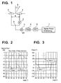
- FIG. 2 shows for a simple model of a patch antenna (for other antenna element characteristics slightly different beam characteristics), the amplitude characteristics of the overall arrangement for both switching states of the phase shifter 3.
- the switching period should not be too low, since otherwise the very cost-effective approach of direct mixing of the RF carrier signal in the LF baseband (so-called homodyne approach, baseband frequency components in the kHz range) would have to be modified accordingly.
- the relative movements of targets or sensor carrier (ego vehicle) must be negligible or compensated in the evaluation (target angle estimation) (determining the upper limit of the switching period, but on the other hand, a homodyne approach (determining the With HF carrier frequencies in the GHz range, switching periods in the range of a few ⁇ s, for example 5 to 50 ⁇ s, are advantageous.
- the angle of the target is obtained by comparing the relative amplitude and phase change in the reception path in both switching states with the two complex-valued directional characteristics of the antenna arrangement (sum and) difference Beam).
- the distance d of both antenna elements - see FIG. 1 - In the range of half the wavelength is, for example, at 24 GHz about 6.5 mm.
- FIG. 4 shows an embodiment, wherein the two antenna elements 1 and 2 are formed here by way of example by four individual radiators. These have the task of vertical arrangement to the road surface after obstruction in the vehicle to bundle the energy in the vertical direction (elevation bundling) in order to obtain a corresponding range here but also to get not too strong reflections from the road itself.
- elevation bundling energy in the vertical direction
- azimuth there is only a small bundling per column, so that the directional diagrams in the azimuth are similar to those in FIG. 2 are very wide, in order to have the largest possible horizontal detection range and especially here the widest possible overlap of both directional diagrams.
- the outlined bushings 9 in FIG. 4 have the task to concentrate the RF components that require a component assembly, such as the 180 ° phase shifter 3, in the plane or on the layer, where even more equipment is required (mixer 4, etc.), so that a double-sided Assembly is avoided.
- the filter 5 is in This embodiment is a low-pass filter TP, if the radar sensor principle is based homodyner approach, that is both sent with an oscillator, not shown here, as well as the received signal is mixed directly into the baseband (direct conversion). Other embodiments are also possible, for example heterodyne approach with mixture in an intermediate frequency level via another oscillator, filter design then as a bandpass.
- FIG. 5a shows yet another way, as the angle determination of the type described above is possible.
- the phase-adjusting element used here is a so-called 180 ° hybrid 10, called Ratrace in the literature. This has the property of dividing a signal incident on a gate equally to the gates opposite here and with a relative phase difference of 180 °, while the fourth gate is insulated. Due to the reciprocity and linearity of this component, it is equally possible to apply two signals to two input ports and to subtract the sum and the difference signal at the two (here) opposite ports, in this case the sum beam and difference beam.
- An advantage of this approach is that both beams are present at the same time, so that the negative influence of target fluctuation or relative movements does not occur here.
- the disadvantage is that both gates for further processing each require their own mixer, filter and AD converter (hardware costs).
- the two gates of the ratrace can also be fed via a suitable changeover switch 11 to a mixer in time division multiplex ( FIG. 5b ).
- FIGS. 6 and 7 still show versions with two columns per antenna element.
- By implementing more than one antenna column per antenna element it is possible to obtain a bundling of the reception energy in a horizontal plane. As a result, a larger antenna gain and thus a greater radar range can be achieved, while the overlap area of the sum and difference beam is thereby narrowed.
- This can be advantageous for functions such as a reversing aid.
- this embodiment may be advantageous for certain functions in which a certain suppression of signals (interferers) in the side area is just desired, for example, from crash barriers or other development on the roadside. This is directly supported by the strong bundling of multi-column antenna elements.
- the phase shifter 3 can be advantageously designed as a PIN diode phase shifter.
- a radar sensor may comprise, in a high integration design, the phase shifter or, if necessary, the switch, signal combining (T-branch, Wilkinson divider, or the like), the mixer and optionally additional low noise preamplifiers (LNAs) in a monolithic microwave integrated (MMIC) circiut).
- the phase shifter or, if necessary, the switch, signal combining (T-branch, Wilkinson divider, or the like), the mixer and optionally additional low noise preamplifiers (LNAs) in a monolithic microwave integrated (MMIC) circiut).
- MMIC monolithic microwave integrated
- phase shifter 3 an RF MEMS 180 ° phase shifter (RF: Radio Frequency, MEMS: Microelectromechanical System) can also be used.
- RF Radio Frequency
- MEMS Microelectromechanical System
- the antenna element may be provided in different designs: individual radiators, columns, several columns together per antenna element, so-called patch radiators, etc.
- switch 11 PIN diode switches or MEMS switches can be used.
Landscapes
- Engineering & Computer Science (AREA)
- Radar, Positioning & Navigation (AREA)
- Remote Sensing (AREA)
- Computer Networks & Wireless Communication (AREA)
- Physics & Mathematics (AREA)
- General Physics & Mathematics (AREA)
- Variable-Direction Aerials And Aerial Arrays (AREA)
- Radar Systems Or Details Thereof (AREA)
Description
- Die Erfindung geht aus von einer Einrichtung zur Messung von Winkelpositionen unter Verwendung von Radarpulsen mit sich gegenseitig überlappende Strahlcharakteristiken mindestens zweier Antennenelemente, gemäß dem Oberbegriff des Anspruches 1, wie aus der
U.S. 5,017,927 bekannt. - Radarsensoren zur Erfassung des nahen Kraftfahrzeugumfeldes (SRR, Short Range Radarsensoren) sind für Funktionen wie Rückfahrhilfe, Einparkhilfe, Parklückenvermessung, Tote-Winkel-Überwachung, langsames Folgefahren oder Precrash-Erkennung vorgesehen.
- Neben der Information über den Abstand relevanter Objekte (andere Fahrzeuge, Fahrspur- oder Parklückenbegrenzungen, Fußgänger, ...) ist auch die Information über deren Winkelposition retativ zum Fahrzeug wichtig, um die Relevanz erkannter Objekte für die jeweilige Funktion zu beurteilen. Stand der Technik ist es, die Winkelrichtung von Objekten über die sogenannte Trilateration zu errechnen. Hierbei werden die Abstandsinformationen mehrerer benachbarter Sensoren herangezogen, um mittels einfacher trigonometrischer Umrechnungen auch die Winkelablage von Zielen zu bestimmen. Nachteilig an diesem Verfahren ist es, dass immer mehrere Sensoren in gewissem Abstand erforderlich sind, auch um die Position nur eines Ziels zu erfahren. Auch müssen diese Sensoren jeweils ein und dasselbe Ziel erfassen, um keine Fehlschätzungen zu erhalten.
- Aus der
WO 00/49423 - Aus M. Skolnik, Introduction to radar systems, second edition, Mc. Graw Hill Book Company 1980, Seiten 160 und 161 ist es bekannt, die Winkelinformation eines Zielobjektes durch zwei sich überlappende Antennen-Strahlcharakteristiken zu gewinnen.
- Mit der Einrichtung gemäß den Merkmalen des Anspruchs 1 ist die Gewinnung von Winkelinformationen aus einem gesamten Radarortungsfeld bei sehr begrenztem zusätzlichen Hardwareaufwand möglich.
- In den Unteransprüchen sind vorteilhafte Ausgestaltungen aufgezeigt.
- Mit den Maßnahmen der Erfindung muss nicht in jedem Empfangspfad ein eigener Abwärtsmischer und eine eigene NF-Verarbeitung vorgesehen sein. Mit der Erfindung ist es möglich, die Messung von Winkelpositionen bereits in einem Einzelsensor zu realisieren. Das Ortungsfeld kann gegenüber einer Realisierung, die nur zur Abstandsmessung dient, nahezu unverändert sein. Der zusätzliche Hardwareaufwand beschränkt sich auf einfache Phaseschieber mit einfacher Signalauswertung.
- Durch die erfindungsgemäße Winkelmessung ist es möglich, die Anzahl der erforderlichen Sensoren für bestimmte Funktionen zu minimieren. Eine Rückfahrhilfe kann mit nur einem winkelmessenden SRR-Sensor ausgestattet werden, wohingegen herkömmliche Systeme drei Sensoren benötigen. Beim langsamen Folgefahren würden mit der erfindungsgemäßen Realisierung nur ein bis zwei Sensoren nötig sein statt drei oder vier Sensoren wie bei herkömmlichen Systemen. Zur Tote-Winkel-Überwachung reicht ein Sensor aus statt der sonst üblichen zwei Sensoren.
- Ausführungsbeispiele der Erfindung werden anhand der Zeichnungen erläutert. Es zeigen
-
Figur 1 eine erfindungsgemäße Realisierung mit Dual-Beam-Antenne und schaltbarem Phasenschieber, -
Figur 2 den Amplitudenverlauf eines Dual-Beam-Sensors, -
Figur 3 den Phasenverlauf eines Dual-Beam-Sensors, -
Figur 4 eine Dual-Beam-Antenne mit Beschaltung, -
Figur 5a und b Dual-Beam-Antennen mit 180°-Hybrid, -
Figur 6 eine Antennenanordnung mit 2x2 Spalten für Zeitmultiplexbetrieb, -
Figur 7 die Antennenanordnung nachFigur 6 mit 180-Hybrid. - Bei der Erfindung wird für die Winkelmessung die bekannte Radar-Monopuls-Technik eingesetzt, bei der über den Vergleich von Empfangssignalen in unterschiedlichen, gegenseitig überlappenden Strahlkeulen und Kenntnis der Strahlungscharakteristiken selbst eine Information über die Winkelablage ableitbar ist (vergleichbar mit einem sogenannten "best fit matching" der empfangenen Signale). Dieses Auswerteverfahren ist sehr ähnlich dem, welches auch beim Long Range Radar (LRR, ACC) eingesetzt wird. Beim LRR-Radar werden drei oder vier Empfangskeulen ausgebildet und deren gegenseitige Überlappung zur Winkelschätzung mittels Vergleich der Empfangssignale herangezogen.
- Bei der erfindungsgemäßen Einrichtung zur Messung von Winkelpositionen werden zwei unterschiedliche Empfangscharakteristiken mit möglichst breitem Überlappungsbereich erzeugt. Dazu werden gemäß
Figur 1 mindestens zwei Antennenelemente 1 und 2 mit jeweils einstellbaren Schwingungsphasen benutzt. Die unterschiedlichen Phasenzustände werden durch ein zwischengeschaltetes HF-Bauelement erzeugt, im Beispiel gemäßFigur 1 ist dieses ein schaltbarer Phasenschieber 3, der in einem der hier dargestellten zwei Antennenpfade zwischengeschaltet ist. Durch Schalten des Phasenschiebers 3 wird die Schwingungsphase von Antennenelement 2 unterschiedlich zu der von Antennenelement 1 eingestellt, wodurch die Richtcharakteristik der Gesamtanordnung maßgeblich zu beeinflussen ist. Die Signale beider Antennenelemente 1 und 2 werden im Empfangspfad nachfolgend additiv zusammengeführt (Summierknoten 8) und einer Mischereinheit 4 (Mischung mit einem Lokaloszillatorsignal, LO) sowie der Weiterverarbeitung (Filterung 5, Analog/Digitalwandlung (ADC) 6, Auswerteeinrichtung 7) zugeführt. -
Figur 2 zeigt beispielhaft für ein einfaches Modell einer Patchantenne (für andere Antennenelement-Charakteristiken ergeben sich geringfügig andere Strahlcharakteristiken) die Amplitudencharakteristiken der Gesamtanordnung für beide Schaltzustände des Phasenschiebers 3. Die Charakteristik von Beam 1 ergibt sich durch gleichphasige Ansteuerung beider Antennenelemente, das heißt der Phasenschieber 3 ist im Schaltzustand 0° (Beam 1 = Summenbeam oder Gleichtaktbeam). In der Hauptstrahlrichtung bildet sich dadurch - durch konstruktive Überlagerung gleichphasiger Anteile - ein Maximum in der gemeinsamen Strahlungscharakteristik. Beam 2 erhält man durch eine Phasenverschiebung von 180° im Pfad von Antennenelement 2 (oder 1), in Hauptstrahlrichtung löschen sich die Anteile von Antennenelement von 1 und 2 dadurch gerade aus (destruktive Überlagerung), so dass die Richtcharakteristik in diese Richtung eine Nullstelle ausbildet (Beam 2 = Differenzbeam oder Gegentaktbeam). Seitlich ergibt sich eine symmetrische Ausformung zweier, im Idealfall identischer Hauptkeulen. InFigur 3 sind die zugehörigen Phasenverläufe beider Empfangscharakteristiken dargestellt. Während die Phase von Beam 1 aus Symmetriegründen (spiegel) symmetrisch zur Hauptstrahlrichtung ist, ergibt sich für Beam 2 ein punktsymmetrischer Verlauf. Dieses ist entscheidend für die beabsichtigte Winkelbestimmung eines Ziels, da nur durch die Unsymmetrie mindestens eines der beiden Phasenverläufe eine Entscheidung darüber möglich ist, ob sich ein Ziel links oder rechts in Bezug zur Orientierung des Sensors befindet. - Zur Winkelbestimmung selbst wird zwischen beiden Phasenzuständen und damit zwischen beiden Empfangs-Richtcharakteristiken hin- und hergeschaltet (Betrieb im Zeitmultiplex). Dieses Schalten erfolgt so schnell, dass der Einfluss von Amplituden- und Phasenänderungen der einfallenden Wellenfront eines Ziels in Folge von Relativbewegungen des Ziels (Zielfluktuationen) oder des Senders in Bezug zur Empfangsantenne vernachlässigbar oder durch entsprechende Korrekturmaßnahmen noch kompensierbar ist. Nur dann ist eine hinreichend genaue Aussage darüber möglich, welcher Anteil an einer relativen Amplituden- und Phasenänderung beider Richtcharakteristiken im Empfangskanal eindeutig der Winkelablage des Ziels zuzuordnen ist und nicht etwa anderer, oben genannter Effekte. Die Schaltperiode sollte andererseits auch nicht zu gering sein, da ansonsten der sehr kostengünstige Ansatz des direkten Mischens des HF-Trägersignals in das NF-Basisband (sogenannter homodyner Ansatz, Basisbandfrequenzanteile im kHz-Bereich) entsprechend modifiziert werden müsste. Zur Gewinnung der optimalen Schaltfrequenz zwischen den Antennencharakteristiken müssen die Relativbewegungen von Zielen bzw. Sensorträger (Ego-Fahrzeug) vernachlässigbar sein oder in der Auswertung (Zielwinkelschätzung) kompensierbar sein (bestimmend für die obere Grenze der Schaltperiode, aber andererseits ein homodyner Ansatz (bestimmend für die untere Grenze der Schaltperiode) verwendbar sein. Bei HF-Trägerfrequenzen im GHz-Bereich sind Schaltperioden im Bereich von wenigen µs z.B. 5 bis 50 µs vorteilhaft.
- Sind diese zeitlichen Effekte (Zielfluktuationen, Relativbewegungen) minimal oder entsprechend kompensiert bzw. durch Korrekturgrößen berücksichtigt, so ergibt sich der Winkel des Ziels durch Vergleich der relativen Amplituden- und Phasenänderung im Empfangspfad in beiden Schaltzuständen mit den beiden komplexwertigen Richtcharakteristiken der Antennenanordnung (Summen- und Differenzbeam). Damit über dem gesamten Winkelbereich keine Mehrdeutigkeiten in Bezug auf den Vergleich der Empfangssignale mit den Richtcharakteristiken auftreten, sollten weitere Keulen (Nebenkeulen) in Beam 1 und 2 vermieden werden. Dies ist möglich, wenn z.B. der Abstand d beider Antennenelemente - siehe
Figur 1 - im Bereich der halben Wellenlänge ist, z.B. bei 24 GHz ca. 6,5 mm. -
Figur 4 zeigt eine Ausführungsform, wobei die beiden Antennenelemente 1 und 2 hier beispielhaft durch jeweils vier Einzelstrahler gebildet werden. Diese haben die Aufgabe, bei senkrechter Anordnung zur Fahrbahnfläche nach Verbauung beim Fahrzeug, die Energie in vertikaler Richtung zu bündeln (Elevationsbündelung), um hierüber eine entsprechende Reichweite zu erlangen aber auch um nicht zu starke Reflexionen von der Fahrbahn selbst zu erhalten. In der Horizontalebene (Azimut) ergibt sich je Spalte nur eine geringe Bündelung, so dass die Richtdiagramme im Azimut ähnlich denen inFigur 2 sehr breit sind, um einen möglichst großen horizontalen Erfassungsbereich und speziell hier auch eine möglichst breite Überlappung beider Richtdiagramme zu haben. - Die skizzierten Durchführungen 9 in
Figur 4 haben die Aufgabe, die HF-Komponenten, die eine Bauteilebestückung erfordern, wie z.B. der 180° Phasenschieber 3, in der Ebene bzw. auf dem Layer zu konzentrieren, wo noch weitere Bestückungen erforderlich sind (Mischer 4, etc.), damit eine doppelseitige Bestückung vermieden wird. Das Filter 5 ist in dieser Ausführung ein Tiefpassfilter TP, sofern dem Radarsensor-Prinzip ein homodyner Ansatz zugrunde liegt, das heißt mit einem Oszillator sowohl gesendet, hier nicht dargestellt, als auch das empfangene Signal direkt ins Basisband gemischt wird (direct conversion). Andere Ausführungsformen sind ebenfalls möglich, z.B. heterodyner Ansatz mit Mischung in eine Zwischenfrequenzebene über weiteren Oszillator, Filterausführung dann als Bandpass. -
Figur 5a zeigt noch eine weitere Möglichkeit, wie die Winkelbestimmung nach oben beschriebener Art möglich ist. Als phasenstellendes Element wird hier ein sogenanntes 180°-Hybrid 10, in der Literatur Ratrace genannt, verwendet. Dieses hat die Eigenschaft, ein an einem Tor einfallendes Signal gleichmäßig an die hier gegenüberliegenden Tore aufzuteilen und mit einem relativen Phasenunterschied von 180°, während das vierte Tor isoliert ist. Aufgrund von Reziprozität und Linearität dieses Bauteils ist es genauso möglich, zwei Signale auf zwei Eingangstore zu geben und an den beiden (hier) gegenüberliegenden Toren jeweils das Summen- und das Differenzsignal abzugreifen, hier also Summenbeam und Differenzbeam. Vorteilhaft an diesem Ansatz ist, dass beide Beams zeitgleich vorliegen, so dass der negative Einfluss von Zielfluktuation oder Relativbewegungen hier nicht auftritt. Nachteilig ist, dass beide Tore zur Weiterverarbeitung jeweils einen eigenen Mischer, Filter und AD-Wandler erfordern (Hardwareaufwand). - Alternativ können die beiden Tore des Ratrace auch über einen geeigneten Umschalter 11 einem Mischer im Zeitmultiplex zugeführt werden (
Figur 5b ). -
Figur 6 und 7 zeigen noch Ausführungen mit jeweils zwei Spalten je Antennenelement. Durch Ausführung mit mehr als einer Antennenspalte pro Antennenelement ist es möglich, in horizontaler Ebene eine Bündelung der Empfangsenergie zu erhalten. Dadurch ist ein größerer Antennengewinn und damit eine größere Radarreichweite erreichbar, während der Überlappungsbereich von Summen- und Differenzbeam dadurch eingeengt wird. Dieses kann für Funktionen wie z.B. eine Rückfahrhilfe vorteilhaft sein. Ebenfalls kann diese Ausführung vorteilhaft sein für bestimmte Funktionen, bei denen eine gewisse Unterdrückung von Signalen (Störern) im Seitenbereich gerade gewünscht ist, z.B. von Leitplanken oder sonstiger Bebauung am Fahrbahnrand. Dieses wird durch die starke Bündelung mehrspaltiger Antennenelemente direkt unterstützt. - Der Phasenschieber 3 kann vorteilhaft als PIN-Dioden-Phasenschieber ausgebildet sein.
- Ein Radarsensor nach der Erfindung kann in einer Hochintegrationsausgestaltung den Phasenschieber oder gegebenenfalls den Umschalter, die Signalzusammenführung (T-Verzweigung, Wilkinson-Teiler, o.ä.), den Mischer und gegebenenfalls zusätzliche rauscharme Vorverstärker (LNAs) in einem MMIC (monolithic microwave integrated circiut) enthalten.
- Als Phasenschieber 3 kann auch ein RF MEMS 180° Phasenschieber (RF: Radio Frequency, MEMS: Microelectromechanical System) verwendet werden.
- Die Antennenelement können in unterschiedlicher Ausführung vorgesehen sein: Einzelstrahler, Spalten, mehrere Spalten gemeinsam je Antennenelement, sogenannte Patchstrahler, etc.
- Als Umschalter 11 können PIN-Dioden-Schalter oder MEMS-Schalter verwendet werden.
Claims (10)
- Einrichtung zur Messung von Winkelpositionen von Objekten unter Verwendung von Radarpulsen und sich gegenseitig überlappenden Antennen-Strahlcharakteristiken mindestens zweier Antennenelemente (1, 2) mit folgenden Merkmalen:- im Signalweg mindestens eines Antennenelements (2) ist ein schaltbarer Phasenschieber (3) vorgesehen, der im Zeitmultiplex zwischen unterschiedlichen Phasenzuständen schaltbar ist und damit die Strahlungscharakteristik des betroffenen Antennenelements ändert,- es ist eine Auswertung (7) vorgesehen zur Auswertung von den addierten Empfangssignalen der mindestens zwei Antennenelemente (1, 2) unter Beteiligung des mindestens einen Antennenelements (2), in dessen Signalweg der schaltbare Phasenschieber (3) vorgesehen ist;dadurch gekennzeichnet, dass
die Einrichtung ausgestaltet ist, den Winkel eines Objekts durch Vergleich der relativen Amplituden- und Phasenänderungen von Radarpulsen im Empfangspfad in beiden Schaltzuständen des mindestens einen schaltbaren Phasenschiebers (3) zu gewinnen. - Einrichtung nach Anspruch 1, dadurch gekennzeichnet, dass der schaltbare Phasenschieber (3) eingerichtet ist, die Phasenzustände 0° und 180° einzunehmen.
- Einrichtung nach einem der Ansprüche 1 oder 2, dadurch gekennzeichnet, dass die mindestens zwei Antennenelemente (1,2) über ein 180°-Hybrid (10) als phasenstellendes Element verbunden sind zur insbesondere zeitgleichen Auswertung von Summen- und Differenzbeam der mindestens zwei Antennenelemente (1,2).
- Einrichtung nach einem der Ansprüche 1 oder 2, dadurch gekennzeichnet, dass die mindestens zwei Antennenelemente (1, 2) über ein 180°-Hybrid (10) als phasenstellendes Element verbunden sind und dass ein Umschalter (11) am Ausgang des 180°-Hybrids vorgesehen ist zur Auswertung von Summen- und Differenzbeam der mindestens zwei Antennenelemente (1, 2) über einen Mischer im Zeitmultiplex.
- Einrichtung nach einem der Ansprüche 1 bis 4, dadurch gekennzeichnet, dass die Umschaltzeit des mindestens einen Phasenschiebers (3) und damit die Umschaltzeit zwischen zwei Strahlcharakteristiken so einstellbar ist, dass die Relativbewegungen von Objekten oder der Antennenelementträger vernachlässigbar oder in der Auswertung kompensierbar sind.
- Einrichtung nach einem der Ansprüche 1 bis 5, dadurch gekennzeichnet, dass die Umschaltzeit des mindestens einen Phasenschiebers (3) und damit die Umschaltzeit zwischen zwei Strahlungscharakteristiken mindestens so einstellbar ist, dass das Homodyn-Prinzip anwendbar ist.
- Einrichtung nach Anspruch 5 oder 6, dadurch gekennzeichnet, dass bei Betrieb im GHz-Bereich die Umschaltzeit im Bereich zwischen 5 und 50 µs einstellbar ist.
- Einrichtung nach einem der Ansprüche 1 bis 7, dadurch gekennzeichnet, dass zur Elevations- und/oder Azimutbündelung mehr als zwei Antennenelemente insbesondere in Zeilen- und Spaltenanordnung vorgesehen sind, wobei vorzugsweise jeweils mindestens zwei Gruppen von Antennenelementen gemeinsam und gleichzeitig auswertbar sind und wobei im Signalweg mindestens einer Gruppe der umschaltbare Phasenschieber (3) angeordnet ist.
- Einrichtung nach einem der Ansprüche 1 bis 8, dadurch gekennzeichnet, dass der mindestens eine Phasenschieber (3) als PIN-Dioden-Phasenschieber oder MEMS-Phasenschieber ausgebildet ist.
- Einrichtung nach einem der Ansprüche 1 bis 9, dadurch gekennzeichnet, dass HF-Komponenten vorgesehen sind, die eine Bauteilbestückung erfordern, welche auf nur einer Seite einer Leiterplatte aufgebracht sind, insbesondere auf der den Antennenelementen (1, 2) abgewandten Seite.
Applications Claiming Priority (3)
| Application Number | Priority Date | Filing Date | Title |
|---|---|---|---|
| DE10256524A DE10256524A1 (de) | 2002-12-04 | 2002-12-04 | Einrichtung zur Messung von Winkelpositionen |
| DE10256524 | 2002-12-04 | ||
| PCT/DE2003/003103 WO2004051308A1 (de) | 2002-12-04 | 2003-09-18 | Einrichtung zur messung von winkelpositionen |
Publications (2)
| Publication Number | Publication Date |
|---|---|
| EP1570296A1 EP1570296A1 (de) | 2005-09-07 |
| EP1570296B1 true EP1570296B1 (de) | 2009-11-25 |
Family
ID=32403692
Family Applications (1)
| Application Number | Title | Priority Date | Filing Date |
|---|---|---|---|
| EP03753311A Expired - Lifetime EP1570296B1 (de) | 2002-12-04 | 2003-09-18 | Einrichtung zur messung von winkelpositionen |
Country Status (5)
| Country | Link |
|---|---|
| US (1) | US7321332B2 (de) |
| EP (1) | EP1570296B1 (de) |
| AT (1) | ATE449972T1 (de) |
| DE (2) | DE10256524A1 (de) |
| WO (1) | WO2004051308A1 (de) |
Families Citing this family (25)
| Publication number | Priority date | Publication date | Assignee | Title |
|---|---|---|---|---|
| US7231197B1 (en) * | 2000-10-27 | 2007-06-12 | Fisher Daniel E | Angle rate interferometer and passive ranger |
| DE102005023432A1 (de) * | 2005-05-20 | 2006-11-30 | Valeo Schalter Und Sensoren Gmbh | Kraftfahrzeug-Radarsystem und Verfahren zum Betrieb eines Kraftfahrzeug-Radarsystems |
| DE102005042729A1 (de) * | 2005-09-05 | 2007-03-08 | Valeo Schalter Und Sensoren Gmbh | Kraftfahrzeug-Radarsystem mit horizontaler und vertikaler Auflösung |
| DE102006058305A1 (de) * | 2006-12-11 | 2008-06-12 | Robert Bosch Gmbh | Verfahren zur Erkennung einer vertikalen Fehlausrichtung eines Radarsensors |
| US9939526B2 (en) | 2007-09-06 | 2018-04-10 | Rockwell Collins, Inc. | Display system and method using weather radar sensing |
| US9354633B1 (en) | 2008-10-31 | 2016-05-31 | Rockwell Collins, Inc. | System and method for ground navigation |
| US9733349B1 (en) | 2007-09-06 | 2017-08-15 | Rockwell Collins, Inc. | System for and method of radar data processing for low visibility landing applications |
| DE102007058241B4 (de) * | 2007-12-04 | 2022-07-07 | Robert Bosch Gmbh | Auswerteverfahren, insbesondere für ein Fahrerassistenzsystem eines Kraftfahrzeugs, zur Objektdetektion mittels eines Radarsensors |
| US20090167514A1 (en) * | 2007-12-31 | 2009-07-02 | Brian Lickfelt | Combined Radar Backup Assist and Blindspot Detector and Method |
| US8558731B1 (en) * | 2008-07-02 | 2013-10-15 | Rockwell Collins, Inc. | System for and method of sequential lobing using less than full aperture antenna techniques |
| US8077078B1 (en) | 2008-07-25 | 2011-12-13 | Rockwell Collins, Inc. | System and method for aircraft altitude measurement using radar and known runway position |
| DE102009029291A1 (de) | 2009-09-09 | 2011-03-10 | Robert Bosch Gmbh | Planare Antenneneinrichtung für eine Radarsensorvorrichtung |
| DE102009046491A1 (de) | 2009-11-06 | 2011-05-12 | Robert Bosch Gmbh | Planare Antenneneinrichtung für eine Radarsensorvorrichtung |
| DE102009047561A1 (de) | 2009-12-07 | 2011-06-09 | Robert Bosch Gmbh | Antenneneinrichtung für eine Radarsensorvorrichtung |
| DE102010064348A1 (de) | 2010-12-29 | 2012-07-05 | Robert Bosch Gmbh | Radarsensor für Kraftfahrzeuge |
| US9019145B1 (en) | 2011-07-14 | 2015-04-28 | Rockwell Collins, Inc. | Ground clutter rejection for weather radar |
| US9262932B1 (en) | 2013-04-05 | 2016-02-16 | Rockwell Collins, Inc. | Extended runway centerline systems and methods |
| DE102013216970A1 (de) * | 2013-08-27 | 2015-03-05 | Robert Bosch Gmbh | Radarsensor für Kraftfahrzeuge |
| KR101907173B1 (ko) * | 2013-12-09 | 2018-10-11 | 주식회사 만도 | 차량용 레이더 시스템 및 그의 방위각 추출 방법 |
| US10928510B1 (en) | 2014-09-10 | 2021-02-23 | Rockwell Collins, Inc. | System for and method of image processing for low visibility landing applications |
| US10705201B1 (en) | 2015-08-31 | 2020-07-07 | Rockwell Collins, Inc. | Radar beam sharpening system and method |
| CN105356069B (zh) * | 2015-11-28 | 2018-12-04 | 成都安智杰科技有限公司 | 一种提高车载雷达测量角度无模糊范围的方法和天线结构 |
| US10228460B1 (en) | 2016-05-26 | 2019-03-12 | Rockwell Collins, Inc. | Weather radar enabled low visibility operation system and method |
| US10353068B1 (en) | 2016-07-28 | 2019-07-16 | Rockwell Collins, Inc. | Weather radar enabled offshore operation system and method |
| CN107845860A (zh) * | 2016-09-21 | 2018-03-27 | 北京行易道科技有限公司 | 天线系统及雷达 |
Family Cites Families (11)
| Publication number | Priority date | Publication date | Assignee | Title |
|---|---|---|---|---|
| US4232266A (en) * | 1978-09-05 | 1980-11-04 | Bell Telephone Laboratories, Incorporated | Technique for sharing a plurality of transponders among a same or larger number of channels |
| US4280128A (en) * | 1980-03-24 | 1981-07-21 | The United States Of America As Represented By The Secretary Of The Army | Adaptive steerable null antenna processor |
| DE3029169C2 (de) * | 1980-08-01 | 1982-06-09 | Standard Elektrik Lorenz Ag, 7000 Stuttgart | Sendeeinrichtung für ein Navigationssystem |
| US5172122A (en) * | 1980-12-29 | 1992-12-15 | Raytheon Company | All weather tactical strike system (AWISS) and method of operation |
| CA1212746A (en) * | 1983-01-31 | 1986-10-14 | R. Ian Macdonald | Optoelectronically switched phase shifter for radar and satellite phased array antennas |
| US5017927A (en) * | 1990-02-20 | 1991-05-21 | General Electric Company | Monopulse phased array antenna with plural transmit-receive module phase shifters |
| US5706012A (en) * | 1995-12-13 | 1998-01-06 | The United States Of America As Represented By The Secretary Of The Navy | Radar system method using virtual interferometry |
| ATE237811T1 (de) * | 1996-05-14 | 2003-05-15 | Honeywell Int Inc | Autonomes landeführungssystem |
| DE60004487T2 (de) | 1999-02-18 | 2004-07-01 | Nederlandse Organisatie Voor Toegepast-Natuurwetenschappelijk Onderzoek Tno | Phasengesteuertes monopulsradarsystem |
| US6504505B1 (en) * | 2000-10-30 | 2003-01-07 | Hughes Electronics Corporation | Phase control network for active phased array antennas |
| DE20321903U1 (de) * | 2002-06-24 | 2012-11-14 | Broadcom Corporation | Antennensystem mit Reduzierter Komplexität, das eineGemultiplexte Empfangskettenverarbeitung verwendet |
-
2002
- 2002-12-04 DE DE10256524A patent/DE10256524A1/de not_active Ceased
-
2003
- 2003-09-18 AT AT03753311T patent/ATE449972T1/de not_active IP Right Cessation
- 2003-09-18 DE DE50312162T patent/DE50312162D1/de not_active Expired - Lifetime
- 2003-09-18 US US10/537,667 patent/US7321332B2/en not_active Expired - Fee Related
- 2003-09-18 EP EP03753311A patent/EP1570296B1/de not_active Expired - Lifetime
- 2003-09-18 WO PCT/DE2003/003103 patent/WO2004051308A1/de not_active Ceased
Also Published As
| Publication number | Publication date |
|---|---|
| DE10256524A1 (de) | 2004-07-01 |
| DE50312162D1 (de) | 2010-01-07 |
| US7321332B2 (en) | 2008-01-22 |
| ATE449972T1 (de) | 2009-12-15 |
| WO2004051308A1 (de) | 2004-06-17 |
| EP1570296A1 (de) | 2005-09-07 |
| US20060250296A1 (en) | 2006-11-09 |
Similar Documents
| Publication | Publication Date | Title |
|---|---|---|
| EP1570296B1 (de) | Einrichtung zur messung von winkelpositionen | |
| DE112011102901B4 (de) | Mehrbereich-Radarsystem | |
| EP1792203B1 (de) | Monostatischer planarer mehrstrahlradarsensor | |
| EP3204788B1 (de) | Abbildender radarsensor mit horizontaler digitaler strahlformung und vertikaler objektvermessung durch phasenvergleich bei zueinander versetzten sendern | |
| DE60205711T2 (de) | Monopuls Radar mit Einstellung der Strahlaufweitung | |
| EP2534730B1 (de) | Radarsensor | |
| DE10354872B4 (de) | Einrichtung zur Erfassung einer Richtung eines Ziels unter Verwendung einer Phasendifferenz von über mehrere Kanäle empfangenen Radiowellensignalen | |
| EP3452847B1 (de) | Kraftfahrzeug mit wenigstens zwei radarsensoren | |
| WO2004061475A1 (de) | Winkelauflösendes antennensystem | |
| DE69828208T2 (de) | Vorausschauender Sensor für Kraftfahrzeuge | |
| WO2006063915A1 (de) | Radarsystem mit adaptiver digitaler empfangs-strahlformung und umschaltbarer sende-richtcharakteristik zur abdeckung von nah- und fernbereich | |
| DE102012102185A1 (de) | Radarvorrichtung, die den kurz- und langreichweitigen Radarbetrieb unterstützt | |
| DE102009032115A1 (de) | Radarsystem mit breitem Erfassungsbereich und Mitteln zur Vermeidung von Mehrdeutigkeiten bei der Winkelmessung | |
| DE60304300T2 (de) | Fahrzeugsensor zur Bestimmung von Abstand und Richtung eines Objektes | |
| DE112010005194T5 (de) | Hinderniserfassungsvorrichtung | |
| WO2018137835A1 (de) | Verfahren zur ermittlung von wenigstens einer objektinformation wenigstens eines objekts, das mit einem radarsystem insbesondere eines fahrzeugs erfasst wird, radarsystem und fahrerassistenzsystem | |
| EP3794373A1 (de) | Mimo-radarsensor für kraftfahrzeuge | |
| DE102007038513A1 (de) | Monostatischer Mehrstrahlradarsensor für Kraftfahrzeuge | |
| DE102009024064A1 (de) | Fahrerassistenzeinrichtung zum Bestimmen eines Zielwinkels eines einrichtungsexternen Objektes und Verfahren zum Korrigieren einer Zielwinkel-Parameter-Kennlinie | |
| EP1431773A2 (de) | Winkelscannendes Radarsystem | |
| DE102017214020A1 (de) | Kraftfahrzeug mit mehreren Radarsensoren zur Umfelderfassung | |
| WO2020225314A1 (de) | Kohärentes, multistatisches radarsystem, insbesondere zur verwendung in einem fahrzeug | |
| DE3789595T2 (de) | Fahrzeugantenne mit verschiebbarem Strahlungsdiagramm. | |
| DE102021212390A1 (de) | Radarvorrichtung und Radarverfahren | |
| EP1969394A1 (de) | Radarvorrichtung |
Legal Events
| Date | Code | Title | Description |
|---|---|---|---|
| PUAI | Public reference made under article 153(3) epc to a published international application that has entered the european phase |
Free format text: ORIGINAL CODE: 0009012 |
|
| 17P | Request for examination filed |
Effective date: 20050704 |
|
| AK | Designated contracting states |
Kind code of ref document: A1 Designated state(s): AT BE BG CH CY CZ DE DK EE ES FI FR GB GR HU IE IT LI LU MC NL PT RO SE SI SK TR |
|
| 17Q | First examination report despatched |
Effective date: 20080814 |
|
| GRAP | Despatch of communication of intention to grant a patent |
Free format text: ORIGINAL CODE: EPIDOSNIGR1 |
|
| GRAS | Grant fee paid |
Free format text: ORIGINAL CODE: EPIDOSNIGR3 |
|
| GRAA | (expected) grant |
Free format text: ORIGINAL CODE: 0009210 |
|
| AK | Designated contracting states |
Kind code of ref document: B1 Designated state(s): AT BE BG CH CY CZ DE DK EE ES FI FR GB GR HU IE IT LI LU MC NL PT RO SE SI SK TR |
|
| REG | Reference to a national code |
Ref country code: GB Ref legal event code: FG4D Free format text: NOT ENGLISH |
|
| REG | Reference to a national code |
Ref country code: CH Ref legal event code: EP |
|
| REG | Reference to a national code |
Ref country code: IE Ref legal event code: FG4D |
|
| REF | Corresponds to: |
Ref document number: 50312162 Country of ref document: DE Date of ref document: 20100107 Kind code of ref document: P |
|
| REG | Reference to a national code |
Ref country code: NL Ref legal event code: VDEP Effective date: 20091125 |
|
| PG25 | Lapsed in a contracting state [announced via postgrant information from national office to epo] |
Ref country code: FI Free format text: LAPSE BECAUSE OF FAILURE TO SUBMIT A TRANSLATION OF THE DESCRIPTION OR TO PAY THE FEE WITHIN THE PRESCRIBED TIME-LIMIT Effective date: 20091125 Ref country code: PT Free format text: LAPSE BECAUSE OF FAILURE TO SUBMIT A TRANSLATION OF THE DESCRIPTION OR TO PAY THE FEE WITHIN THE PRESCRIBED TIME-LIMIT Effective date: 20100325 Ref country code: SE Free format text: LAPSE BECAUSE OF FAILURE TO SUBMIT A TRANSLATION OF THE DESCRIPTION OR TO PAY THE FEE WITHIN THE PRESCRIBED TIME-LIMIT Effective date: 20091125 |
|
| PG25 | Lapsed in a contracting state [announced via postgrant information from national office to epo] |
Ref country code: SI Free format text: LAPSE BECAUSE OF FAILURE TO SUBMIT A TRANSLATION OF THE DESCRIPTION OR TO PAY THE FEE WITHIN THE PRESCRIBED TIME-LIMIT Effective date: 20091125 Ref country code: CY Free format text: LAPSE BECAUSE OF FAILURE TO SUBMIT A TRANSLATION OF THE DESCRIPTION OR TO PAY THE FEE WITHIN THE PRESCRIBED TIME-LIMIT Effective date: 20091125 |
|
| REG | Reference to a national code |
Ref country code: IE Ref legal event code: FD4D |
|
| PG25 | Lapsed in a contracting state [announced via postgrant information from national office to epo] |
Ref country code: BG Free format text: LAPSE BECAUSE OF FAILURE TO SUBMIT A TRANSLATION OF THE DESCRIPTION OR TO PAY THE FEE WITHIN THE PRESCRIBED TIME-LIMIT Effective date: 20100225 Ref country code: IE Free format text: LAPSE BECAUSE OF FAILURE TO SUBMIT A TRANSLATION OF THE DESCRIPTION OR TO PAY THE FEE WITHIN THE PRESCRIBED TIME-LIMIT Effective date: 20091125 Ref country code: ES Free format text: LAPSE BECAUSE OF FAILURE TO SUBMIT A TRANSLATION OF THE DESCRIPTION OR TO PAY THE FEE WITHIN THE PRESCRIBED TIME-LIMIT Effective date: 20100308 Ref country code: DK Free format text: LAPSE BECAUSE OF FAILURE TO SUBMIT A TRANSLATION OF THE DESCRIPTION OR TO PAY THE FEE WITHIN THE PRESCRIBED TIME-LIMIT Effective date: 20091125 Ref country code: EE Free format text: LAPSE BECAUSE OF FAILURE TO SUBMIT A TRANSLATION OF THE DESCRIPTION OR TO PAY THE FEE WITHIN THE PRESCRIBED TIME-LIMIT Effective date: 20091125 Ref country code: RO Free format text: LAPSE BECAUSE OF FAILURE TO SUBMIT A TRANSLATION OF THE DESCRIPTION OR TO PAY THE FEE WITHIN THE PRESCRIBED TIME-LIMIT Effective date: 20091125 Ref country code: NL Free format text: LAPSE BECAUSE OF FAILURE TO SUBMIT A TRANSLATION OF THE DESCRIPTION OR TO PAY THE FEE WITHIN THE PRESCRIBED TIME-LIMIT Effective date: 20091125 |
|
| PG25 | Lapsed in a contracting state [announced via postgrant information from national office to epo] |
Ref country code: CZ Free format text: LAPSE BECAUSE OF FAILURE TO SUBMIT A TRANSLATION OF THE DESCRIPTION OR TO PAY THE FEE WITHIN THE PRESCRIBED TIME-LIMIT Effective date: 20091125 Ref country code: SK Free format text: LAPSE BECAUSE OF FAILURE TO SUBMIT A TRANSLATION OF THE DESCRIPTION OR TO PAY THE FEE WITHIN THE PRESCRIBED TIME-LIMIT Effective date: 20091125 |
|
| PLBE | No opposition filed within time limit |
Free format text: ORIGINAL CODE: 0009261 |
|
| STAA | Information on the status of an ep patent application or granted ep patent |
Free format text: STATUS: NO OPPOSITION FILED WITHIN TIME LIMIT |
|
| PG25 | Lapsed in a contracting state [announced via postgrant information from national office to epo] |
Ref country code: GR Free format text: LAPSE BECAUSE OF FAILURE TO SUBMIT A TRANSLATION OF THE DESCRIPTION OR TO PAY THE FEE WITHIN THE PRESCRIBED TIME-LIMIT Effective date: 20100226 |
|
| 26N | No opposition filed |
Effective date: 20100826 |
|
| BERE | Be: lapsed |
Owner name: ROBERT BOSCH G.M.B.H. Effective date: 20100930 |
|
| PG25 | Lapsed in a contracting state [announced via postgrant information from national office to epo] |
Ref country code: IT Free format text: LAPSE BECAUSE OF FAILURE TO SUBMIT A TRANSLATION OF THE DESCRIPTION OR TO PAY THE FEE WITHIN THE PRESCRIBED TIME-LIMIT Effective date: 20091125 |
|
| PG25 | Lapsed in a contracting state [announced via postgrant information from national office to epo] |
Ref country code: MC Free format text: LAPSE BECAUSE OF NON-PAYMENT OF DUE FEES Effective date: 20100930 |
|
| REG | Reference to a national code |
Ref country code: CH Ref legal event code: PL |
|
| PG25 | Lapsed in a contracting state [announced via postgrant information from national office to epo] |
Ref country code: BE Free format text: LAPSE BECAUSE OF NON-PAYMENT OF DUE FEES Effective date: 20100930 Ref country code: LI Free format text: LAPSE BECAUSE OF NON-PAYMENT OF DUE FEES Effective date: 20100930 Ref country code: CH Free format text: LAPSE BECAUSE OF NON-PAYMENT OF DUE FEES Effective date: 20100930 |
|
| PG25 | Lapsed in a contracting state [announced via postgrant information from national office to epo] |
Ref country code: AT Free format text: LAPSE BECAUSE OF NON-PAYMENT OF DUE FEES Effective date: 20100918 |
|
| PG25 | Lapsed in a contracting state [announced via postgrant information from national office to epo] |
Ref country code: LU Free format text: LAPSE BECAUSE OF NON-PAYMENT OF DUE FEES Effective date: 20100918 Ref country code: HU Free format text: LAPSE BECAUSE OF FAILURE TO SUBMIT A TRANSLATION OF THE DESCRIPTION OR TO PAY THE FEE WITHIN THE PRESCRIBED TIME-LIMIT Effective date: 20100526 |
|
| PG25 | Lapsed in a contracting state [announced via postgrant information from national office to epo] |
Ref country code: TR Free format text: LAPSE BECAUSE OF FAILURE TO SUBMIT A TRANSLATION OF THE DESCRIPTION OR TO PAY THE FEE WITHIN THE PRESCRIBED TIME-LIMIT Effective date: 20091125 |
|
| PGFP | Annual fee paid to national office [announced via postgrant information from national office to epo] |
Ref country code: GB Payment date: 20120920 Year of fee payment: 10 |
|
| PGFP | Annual fee paid to national office [announced via postgrant information from national office to epo] |
Ref country code: DE Payment date: 20121122 Year of fee payment: 10 Ref country code: FR Payment date: 20121008 Year of fee payment: 10 |
|
| GBPC | Gb: european patent ceased through non-payment of renewal fee |
Effective date: 20130918 |
|
| REG | Reference to a national code |
Ref country code: FR Ref legal event code: ST Effective date: 20140530 |
|
| REG | Reference to a national code |
Ref country code: DE Ref legal event code: R119 Ref document number: 50312162 Country of ref document: DE Effective date: 20140401 |
|
| PG25 | Lapsed in a contracting state [announced via postgrant information from national office to epo] |
Ref country code: GB Free format text: LAPSE BECAUSE OF NON-PAYMENT OF DUE FEES Effective date: 20130918 |
|
| PG25 | Lapsed in a contracting state [announced via postgrant information from national office to epo] |
Ref country code: DE Free format text: LAPSE BECAUSE OF NON-PAYMENT OF DUE FEES Effective date: 20140401 Ref country code: FR Free format text: LAPSE BECAUSE OF NON-PAYMENT OF DUE FEES Effective date: 20130930 |