EP2532923A2 - Cathéter pour commande antimicrobienne et son procédé de fabrication - Google Patents
Cathéter pour commande antimicrobienne et son procédé de fabrication Download PDFInfo
- Publication number
- EP2532923A2 EP2532923A2 EP12174495A EP12174495A EP2532923A2 EP 2532923 A2 EP2532923 A2 EP 2532923A2 EP 12174495 A EP12174495 A EP 12174495A EP 12174495 A EP12174495 A EP 12174495A EP 2532923 A2 EP2532923 A2 EP 2532923A2
- Authority
- EP
- European Patent Office
- Prior art keywords
- sleeve
- plunger
- tensioner
- circlip
- retainer
- Prior art date
- Legal status (The legal status is an assumption and is not a legal conclusion. Google has not performed a legal analysis and makes no representation as to the accuracy of the status listed.)
- Granted
Links
Images


Classifications
-
- F—MECHANICAL ENGINEERING; LIGHTING; HEATING; WEAPONS; BLASTING
- F16—ENGINEERING ELEMENTS AND UNITS; GENERAL MEASURES FOR PRODUCING AND MAINTAINING EFFECTIVE FUNCTIONING OF MACHINES OR INSTALLATIONS; THERMAL INSULATION IN GENERAL
- F16H—GEARING
- F16H7/00—Gearings for conveying rotary motion by endless flexible members
- F16H7/08—Means for varying tension of belts, ropes, or chains
- F16H7/0829—Means for varying tension of belts, ropes, or chains with vibration damping means
- F16H7/0836—Means for varying tension of belts, ropes, or chains with vibration damping means of the fluid and restriction type, e.g. dashpot
-
- F—MECHANICAL ENGINEERING; LIGHTING; HEATING; WEAPONS; BLASTING
- F16—ENGINEERING ELEMENTS AND UNITS; GENERAL MEASURES FOR PRODUCING AND MAINTAINING EFFECTIVE FUNCTIONING OF MACHINES OR INSTALLATIONS; THERMAL INSULATION IN GENERAL
- F16H—GEARING
- F16H7/00—Gearings for conveying rotary motion by endless flexible members
- F16H7/08—Means for varying tension of belts, ropes, or chains
- F16H7/0848—Means for varying tension of belts, ropes, or chains with means for impeding reverse motion
-
- F—MECHANICAL ENGINEERING; LIGHTING; HEATING; WEAPONS; BLASTING
- F16—ENGINEERING ELEMENTS AND UNITS; GENERAL MEASURES FOR PRODUCING AND MAINTAINING EFFECTIVE FUNCTIONING OF MACHINES OR INSTALLATIONS; THERMAL INSULATION IN GENERAL
- F16H—GEARING
- F16H7/00—Gearings for conveying rotary motion by endless flexible members
- F16H7/08—Means for varying tension of belts, ropes, or chains
- F16H2007/0802—Actuators for final output members
- F16H2007/0806—Compression coil springs
-
- F—MECHANICAL ENGINEERING; LIGHTING; HEATING; WEAPONS; BLASTING
- F16—ENGINEERING ELEMENTS AND UNITS; GENERAL MEASURES FOR PRODUCING AND MAINTAINING EFFECTIVE FUNCTIONING OF MACHINES OR INSTALLATIONS; THERMAL INSULATION IN GENERAL
- F16H—GEARING
- F16H7/00—Gearings for conveying rotary motion by endless flexible members
- F16H7/08—Means for varying tension of belts, ropes, or chains
- F16H2007/0802—Actuators for final output members
- F16H2007/0812—Fluid pressure
- F16H2007/0817—Fluid pressure with means for venting unwanted gas
-
- F—MECHANICAL ENGINEERING; LIGHTING; HEATING; WEAPONS; BLASTING
- F16—ENGINEERING ELEMENTS AND UNITS; GENERAL MEASURES FOR PRODUCING AND MAINTAINING EFFECTIVE FUNCTIONING OF MACHINES OR INSTALLATIONS; THERMAL INSULATION IN GENERAL
- F16H—GEARING
- F16H7/00—Gearings for conveying rotary motion by endless flexible members
- F16H7/08—Means for varying tension of belts, ropes, or chains
- F16H7/0848—Means for varying tension of belts, ropes, or chains with means for impeding reverse motion
- F16H2007/0853—Ratchets
- F16H2007/0855—Ratchets comprising a clip member engaging with the rack teeth
-
- F—MECHANICAL ENGINEERING; LIGHTING; HEATING; WEAPONS; BLASTING
- F16—ENGINEERING ELEMENTS AND UNITS; GENERAL MEASURES FOR PRODUCING AND MAINTAINING EFFECTIVE FUNCTIONING OF MACHINES OR INSTALLATIONS; THERMAL INSULATION IN GENERAL
- F16H—GEARING
- F16H7/00—Gearings for conveying rotary motion by endless flexible members
- F16H7/08—Means for varying tension of belts, ropes, or chains
- F16H7/0848—Means for varying tension of belts, ropes, or chains with means for impeding reverse motion
- F16H2007/0859—Check valves
-
- F—MECHANICAL ENGINEERING; LIGHTING; HEATING; WEAPONS; BLASTING
- F16—ENGINEERING ELEMENTS AND UNITS; GENERAL MEASURES FOR PRODUCING AND MAINTAINING EFFECTIVE FUNCTIONING OF MACHINES OR INSTALLATIONS; THERMAL INSULATION IN GENERAL
- F16H—GEARING
- F16H7/00—Gearings for conveying rotary motion by endless flexible members
- F16H7/08—Means for varying tension of belts, ropes, or chains
- F16H2007/0876—Control or adjustment of actuators
- F16H2007/0878—Disabling during transport
Definitions
- the invention pertains to the field of tensioners. More particularly, the invention pertains to a modular hydraulic tensioner with a ratchet.
- Timing systems for an internal combustion engines can be controlled by chain transmission, in which the chain is wrapped on two or more sprockets, one of which is a drive sprocket and takes its drive (even indirectly) from the drive shaft to transmit it to one or more driven shafts.
- a fixed member generally a cylinder
- a movable member generally a piston, mobile inside the cylinder
- a shoe placed in contact with the chain to tension it the piston is pushed out of the cylinder towards the shoe disposed against the chain, by the combined action of a spring and pressurized fluid (generally oil) fed into the cylinder chamber through a check valve.
- a spring and pressurized fluid generally oil
- European Patent No. 1,188,955 discloses overcoming the drawback, by coupling the cylinder to a pawl which, interacting with a rack coupled to the piston prevents the piston from returning into the cylinder when pressurized fluid is not available.
- the arrangement also includes an anti-rotation means such as, for example, a closed longitudinal slot, formed on the outside wall of the piston along a generatrix of the piston.
- the anti-rotation means or device further prevents the piston from accidentally slipping out of the cylinder. But, when a tensioner is removed from an engine, the anti-rotation means do not allow, without involving actions which are normally long and expensive, the piston to be returned into the cylinder. For example, facilitating the transport and the storage of the tensioner and/or re-using the tensioner for another engine involves actions which are normally long and expensive. Examples of other anti-rotation devices or means are also disclosed in US Patent No. 4,634,407 , US Patent No. 5,873,799 , US Patent No. 6,315,235 , and US Patent Publication No. 2006/0084538 .
- the tensioner for belt includes piston/cylinder units which can be transported separately from the housing and belt as in US 6,561,936 , or in US 6,855,079 in which the belt tensioner has a multi-part construction that allows the lever arms and pulleys with different sizes and shapes to be used on the same housing and base.
- INSERT PAGE 3a >
- a modular tensioner system for an engine including a modular tensioner and an application specific carrier.
- the application specific carrier receives the modular tensioner and has a corresponding feature for receiving the integral anti-rotation device of the modular tensioner.
- the modular tensioner includes a sleeve, hollow plunger, retainer, circlip, and biasing element.
- the sleeve has an open end and a closed end, with the closed end of the sleeve having an integral anti-rotation device.
- the integral anti-rotation device may be a key or a step.
- the hollow plunger is slidably received by the sleeve.
- the plunger has circumferential teeth and forms a fluid chamber with the sleeve.
- the retainer has a first end with an edge, a second end, and a central hollow for receiving the plunger and the sleeve.
- the retainer may be fastened to the sleeve allowing axial adjustments and tailoring of the backlash based on the application of the tensioner system.
- a circlip engages the circumferential teeth of the plunger and in combination with the retainer guides the extension of the plunger from the sleeve and limits the axial movement of the circlip away from the carrier.
- the circlip contacts the edge of the first end of the retainer, such that the circlip ratchets from circumferential tooth to tooth.
- a first advantage is the modular tensioner design for power transmission systems.
- the modular design provides flexibility in mounting the modular tensioner assembly to the engine via an application specific carrier.
- the tensioner module may be installed in a cast or machined metallic carrier, or secured via an insert molding process to a suitable molded material.
- a second advantage of the present invention is the backlash adjustability. Fastening of the retainer and sleeve allows for axial adjustment of the components allowing the amount of backlash to be tailored to each application. This also allows a singe base module to be fitted to numerous power transmission systems.
- the generic JP-A-2006090449 discloses a chain tensioner capable of automatically releasing a push-in condition of a plunger 4 thanks to an engaging piece 22 supported on a tip part outer circumference of an housing 1 having a cylinder chamber 3 in which the plunger 4 slidably built, said engaging pieces 22 having a bent piece part 22a and a pin hole 24 on a tip part of the bent piece part 22a.
- the bent piece part 22a is elastically deformed toward an outer circumference of the plunger 4, the plunger 4 is kept in the push-in condition by engagement of the engaging pin 20 in the pin hole 24.
- the plunger 4 is pushed in with chain tensed by start of an engine, engagement of the engaging pin 20 and the pin hole 24 is released by elastic deformation of restoring elasticity of the bent piece part 22a, and tension of the chain is retained constant by moving the plunger 4 outward by pressure of the spring 6.
- a third advantage of the present invention is an integral anti-rotation device that mates with a corresponding feature in the application specific carrier. This limits module rotation in the carrier and allows for easy tensioner service and reset.
- a fourth advantage of the present invention is a reduction in ratchet noise achieved by the placement of a damping element at the interface of the sleeve and the carrier.
- the damping element is designed that upon clip impact on the sleeve, the sleeve is allowed to back travel a determined distance before coming in hard contact with the carrier.
- the viscoelastic nature of the damping element dissipates energy introduced by the clip contacting the sleeve.
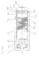
- Figures 1 and 2a shows schematics of a modular tensioner of a tensioner system of a first embodiment.
- Figure 2b shows a sectional view of the modular tensioner of the first embodiment.
- Figure 3 shows a diagrammatical sectional view of the modular tensioner of the first embodiment.
- Figures 4a and 4b show the modular tensioner of the first embodiment at the end of the working stroke and mechanical stroke respectively.
- the modular tensioner system of the first embodiment includes a separate carrier 15 that receives a modular tensioner.
- the modular tensioner includes a hollow plunger 8 slidably fit in a sleeve 1 with circumferential ratchet teeth 8a and a stop groove 13 for accepting a circlip 9 to limit back drive of the plunger 8.
- a hollow chamber 17 is formed between the sleeve 1 and the hollow plunger 8.
- a check valve 3 is also found within the hollow chamber 17 .
- the spring 4 biases the plunger 8 away from the application specific carrier 15.
- An O-ring 5 is also present in the outside of the sleeve 1 to prevent rattling between the application specific carrier 15 and the sleeve 1, as well as provide module retention in the carrier during shipping.
- the plunger 8, sleeve 1, circlip 9, retainer 6, spring 4, and vent device 7 are packaged as a single base module tensioner or modular tensioner with the ability to mate with various suitable carriers 15.
- a hollow retainer piece 6 is received by the sleeve 1 and encompasses a portion of both the sleeve 1 and the plunger 8.
- the plunger 8 may extend out through a central hollow of the retainer 6.
- the top or first end of the retainer 6 has curled edges or a lip 6a. The edges 6a do not contact or interfere with the circumferential ratchet teeth 8a of the plunger 8.
- the backlash of the system is determined by where the retainer 6 is fastened 16 to the sleeve 1 as shown in Figure 1 .
- the placement of the fix or fastening 16 will vary based on the amount of backlash required by the system and the application.
- the backlash is equal to the distance between the top of the retainer lip 6a to the top of the sleeve 1. Fastening of the retainer 6 and sleeve 1 allows for axial adjustment of the components,
- the retainer 6 may be fixed to the sleeve 1 by a mechanical means or chemical means.
- An anti-rotation device may be included with the tensioner system.
- a key 14 is integrally formed at the bore end of the sleeve 1 and is received by a corresponding slot in the application specific carrier 15.
- a step 24 at the end of the sleeve 1, shown in Figure 8b with a radius sharing the same center as the outer diameter of the plunger 8 may also be present in the tensioner system. The step 24 would engage a corresponding pocket in the application specific carrier 15.
- a circlip 9 engages a portion of the plunger 8 that is not received by the sleeve 1 or within the central hollow of the retainer 6.
- the retainer 6 guides the plunger 8 extension as well as limit the axial movement of the circlip 9 in the forward direction away from the carrier 15 of the tensioner.
- the position of the plunger 8 relative to the retainer 6 may be locked into position by the locking pin 10 for shipment.
- the resilient damping element 18 is an element with a viscoelastic nature.
- the resilient element 18 may be a modular O-ring, a rubber washer, a Belleville washer, or other similar device.
- the combined action of the spring 4 and pressurized fluid in the hollow chamber 17 biases the plunger 8 away from and out of the sleeve 1, so that the plunger 8 comes to bear against a shoe or tensioner arm (omitted from the figures).
- the circlip 9 moves or ratchets from circumferential ratchet tooth 8a to circumferential ratchet tooth 8a, until the circlip 9 engages the last circumferential ratchet tooth defining the end of the tensioner's working stroke and the curled ends 6a of the retainer 6 contact the circlip 9 as shown in Figure 4a .
- the plunger 8 may move further away from the sleeve 1, to a position corresponding to the end of the mechanical stroke of the tensioner in which the circlip 9 engages the stop groove 13 on the outer circumference of the plunger 8 and the curled ends 6a of the retainer 6 contact the circlip 9 as shown in Figure 4b .
- Figures 5a-5g show various positions and views of the modular tensioner system of a second embodiment.
- the modular tensioner system of the second embodiment includes a separate carrier 15 that receives the modular tensioner.
- the modular tensioner includes a hollow plunger 58 slidably fit in a single hollow sleeve 70a, 70b with a cutout 71a with a window 71 b separating a first part 70a and a second part 70b of the single hollow sleeve.
- the plunger 58 may extend out of the hollow of the sleeve 70a, 70b.
- the plunger 58 has with two sets of circumferential ratchet teeth 58a, 58b separated by a smooth circumferential portion 58c and a stop groove 63 for accepting a circlip 59 to limit back drive of the plunger 58.
- a hollow chamber 67 is formed between the sleeve 70a, 70b and the hollow plunger 58.
- a check valve 53 in fluid communication with a source of pressurized fluid (not shown).
- a biasing spring 54 biases the plunger 58 away from the application specific carrier 15.
- the plunger 58, sleeve 70a, 70b, circlip 59, spring 54, and vent device 57 are packaged as a single base module tensioner or modular tensioner with the ability to mate with various suitable carriers 15.
- a circlip 59 engages the first set of circumferential teeth 58a on the outer circumference of the plunger 58 is received in the window 71b of the cutout 71a between the sleeve parts 70a, 70b of the single sleeve.
- the circlip 59 is prevented from engaging the second set of circumferential ratchet teeth 58b by the smooth circumferential portion 58c.
- the sleeve parts 70a, 70b and the circlip 59 guide the plunger 58 extension as well as limit the axial movement of the circlip 59 in the forward direction away from the application specific carrier 15 of the tensioner.
- the length of the cutout 71a is equal to the amount of backlash of the modular tensioner of the second embodiment.
- the position of the plunger 58 relative to the sleeve 70a, 70b may be locked into position by a locking clip 69 for shipment.
- the locking clip 69 engages the second set of ratchet teeth 58b on the outer circumference of the plunger 58.
- the locking clip 59 is prevented from engaging the first set of circumferential ratchet teeth 58b by the smooth circumferential portion 58c.
- the plunger 58 is pushed back towards the application specific carrier 15 and then the locking clip 69 is collapsed in, so that the outer diameter of the clip 69 is smaller than the inner diameter of sleeve part 70b, and the clip 69 is allowed to expand out into a notch 70c in sleeve part 70b as shown in Figure 5a .
- the plunger 58 is pushed back towards the application specific carrier 15 and then the locking clip 69 is collapsed in, so that the outer diameter of the locking clip 69 is smaller than the inner diameter of sleeve part 70b and the plunger 58 with the locking clip 69 engaging a ratchet tooth of the second set of plunger teeth 58b may move away from the application specific carrier 15 and sleeve 70b as shown in Figures 5b , 5d , 5g , and 6 .
- an anti-rotation device 14, 24 as discussed above and shown in Figures 1 , 3 , 8a, and 8b may be present at the end of the sleeve 70a of the modular tensioner system of the second embodiment.
- the noise prevention device or resilient damping element 18 may also be present in the modular tensioner system of the second embodiment between the sleeve 70a, 70b and application specific carrier 15 as discussed above and shown in Figures 3 and 11a , so that when the circlip 59 is jumping teeth as shown in Figures 5b and 5c , the sleeve 70a, 70b is allowed to back travel towards the application specific carrier 15 a predetermined distance before coming into hard contact with the application specific carrier 15.
- the circlip 59 moves or ratchets from circumferential ratchet tooth to ratchet tooth of the first set of ratchet teeth 58a on the plunger 58, until the circlip 59 engages the stop groove 63 on the outer circumference of the plunger 58 associated with the first set of ratchet teeth 58a and the circlip 59 contacts the edge of the second sleeve part 70b as shown in Figure 6 .
- Figures 5h through 5j show another anti-rotation device that may be used with a modular tensioner system of the second embodiment.
- the single hollow sleeve 70a, 70b may be replaced with single hollow sleeve 270a, 270b with a cutout 271a separating the first part 270a and the second part 270b of the single hollow sleeve.
- the plunger 58 (not shown) may extend out of the hollow of the sleeve 270a, 270b.
- a groove 270c in the hollow sleeve 270, 270b is present for receiving circlip 59.
- Also present within sleeve part 270b is a hollow for receiving a locking pin 69.
- a portion of the single hollow sleeve 270a, 270b is milled, creating a milling face 202 that mates with a corresponding feature of the carrier and prevents rotation of the sleeve within the carrier.
- Figures 7a-7j show various positions and views of the modular tensioner system of a third embodiment.
- the modular tensioner system of the third embodiment includes a separate carrier 15 that receives a modular tensioner.
- the modular tensioner includes a hollow plunger 108 slidably fit in a sleeve 101 with circumferential ratchet teeth 108a and a stop groove 113 for accepting a circlip 109 to limit back drive of the plunger 108.
- a hollow chamber 117 is formed between the sleeve 101 and the hollow plunger 108.
- a check valve 103 At the bottom or bore end of the hollow chamber 117 is a check valve 103 in fluid communication with a source of pressurized fluid (not shown).
- a biasing spring 104 and vent device 107 is also found within the hollow chamber 117. The spring 104 biases the plunger 108 away from the application specific carrier 15.
- An O-ring 105 is also present on the outside of the sleeve 101 to prevent rattling between the application specific carrier 15 and the sleeve 101.
- the plunger 108, sleeve 101, circlip 109, retainer 106, spring 104, and vent device 107 are packaged as a single base module tensioner or modular tensioner with the ability to mate with various suitable carriers 15.
- a hollow retainer piece 106 is received by the sleeve 101 and encompasses a portion of both the sleeve 101 and the plunger 108.
- the plunger 108 may extend out through a central hollow of the retainer 106.
- the top or first end of the retainer 106 has folded over edges 106a that have been rolled ninety degrees, in comparison to the folded, 180 degree edges of the first embodiment. The edges 106a do not contact or interfere with the circumferential ratchet teeth 108a of the plunger 108.
- the backlash of the system is determined by where the retainer 106 is fastened to the sleeve 101. The placement of the fix will vary based on the amount of backlash required by the system and the application.
- the backlash is equal to the distance between the top of the retainer 106 to the top of the sleeve 101. Fastening of the retainer 106 and sleeve 101 allows for axial adjustment of the components, therefore allowing the amount of backlash to be tailored to each application the tensioner is used in. This feature also permits a single base module tensioner to be fitted to numerous power transmission systems.
- the retainer 106 may be fixed to the sleeve 101 by a mechanical means or chemical adhesion.
- an anti-rotation device 14, 24 as discussed above and shown in Figures 1 , 3 , 8a, and 8b may be present at the end of the sleeve 101 of the modular tensioner system of the second embodiment.
- the noise prevention device or resilient damping element 18 may also be present in the modular tensioner system of the third embodiment between the sleeve 101 and carrier 15 as discussed above and shown in Figures 3 and 11a ,so that when the circlip 109 is jumping teeth as shown in Figures 7g , the sleeve 109 is allowed to back travel towards the application specific carrier 15 a predetermined distance before coming into hard contact with the application specific carrier 15.
- a circlip 109 engages a portion of the plunger 108 that is not received by the sleeve 101 within the hollow of the retainer 106.
- the retainer 106 and circlip 109 guide the plunger 108 extension as well as limit the axial movement of the circlip 109 in the forward direction away from the application specific carrier 15 of the tensioner.
- the positioning of retainer 106, circlip 109, and sleeve 101 also prevent the pushing of the plunger 108 back towards the application specific carrier 15 or sleeve 101, since the circlip 109, while engaging a ratchet tooth108a on the plunger 108 will come into contact with the top of the sleeve 101 as shown in Figure 7f , preventing the plunger 108 from moving further back towards the sleeve 101.
- the position of the plunger 108 relative to the retainer 106 may be locked into position by a locking pin, similar to that shown in Figure 1 for shipment.
- the plunger 108 may move further away from the sleeve 101, to a position corresponding to the end of the mechanical stroke of the tensioner in which the circlip 109 engages the stop groove 113 on the outer circumference of the plunger 108 and the rolled ends 106a of the retainer 106 contact the circlip 109 as shown in Figure 7h .
- Figures 9 through 12b shows various positions and views of modular tensioner system of a fourth embodiment.
- the modular tensioner system of the fourth embodiment includes a separate carrier 15 that receives a modular tensioner.
- the modular tensioner includes a hollow plunger 158 slidably fit in a sleeve 151 with circumferential ratchet teeth 158a and a stop groove 163 for accepting a circlip 159 to limit back drive of the plunger 158.
- a hollow chamber 167 is formed between the sleeve 151 and the hollow plunger 158.
- a check valve 153 is also found within the hollow chamber 167.
- the spring 154 biases the plunger 158 away from the application specific carrier 15.
- An O-ring 155 is also present in the outside of the sleeve 151 to prevent rattling between the application specific carrier 15 and the sleeve 151.
- the plunger 158, sleeve 151, circlip 159, retainer 156, spring 154 and vent device 157 are packages as a single base module tensioner or modular tensioner with the ability to mate with various suitable carriers 15.
- a hollow retainer piece 156 is received by the sleeve 151 and encompasses a portion of both the sleeve 151 and the plunger 158.
- the plunger 158 may extend out through a central hollow of the retainer 156.
- the top or first end of the retainer 156 has curled edges 156a as shown in Figure 11b .
- the edges 156a do not contact or interfere with the circumferential ratchet teeth 158a of the plunger 158.
- the backlash of the system is determined by where the sleeve 151 is fastened 166 to the retainer 156 as shown in Figure 9 .
- the placement of the fix or fastening 166 will vary based on the amount of backlash required by the system and the application.
- the backlash is equal to the distance between the curled edge of the retainer 156 to the top of the sleeve 151. Fastening of the retainer 156 and sleeve 151 allows for axial adjustment of the components, therefore allowing the amount of backlash to be tailored to each application the tensioner is used in. This feature also permits a single base module tensioner to be fitted to numerous power transmission systems.
- An anti-rotation device may be included with the tensioner system.
- a key is integrally formed at the end of the sleeve 151 and is received by a corresponding slot in the application specific carrier 15.
- Another anti-rotation device that may be included is a tang 170 formed integrally with the retainer, which engages a notch in the carrier 15.
- a circlip 159 engages a portion of the plunger 158 that is not received by the sleeve 151 within the hollow of the retainer 156.
- the retainer 156 and circlip 159 guide the plunger 158 extension as well as limit the axial movement of the circlip 159 in the forward direction away from the carrier 15 of the tensioner.
- the position of the plunger 158 relative to the retainer 156 may be locked into position by the locking pin 160 for shipment.
- the resilient damping element 168 is an element with a viscoelastic nature.
- the resilient element 168 may be a modular O-ring, a rubber washer, a Belleville washer, or other similar device.
- an integral feature, for example an undercut is present at the end of the sleeve.
- the circlip 159 moves or ratchets from circumferential ratchet tooth 158a to circumferential ratchet tooth 158a, until the circlip 159 engages the last circumferential tooth defining the end of the tensioner's working stroke and the curled ends 156a of the retainer 156 contact the circlip 159 as shown in Figure 12a .
- the plunger 158 may move further away from the sleeve 151, to a position corresponding to the end of the mechanical stroke of the tensioner in which the circlip 159 engages the stop groove 163 on the outer circumference of the plunger 158 and the curled ends 156a of the retainer 156 contact the circlip 159 as shown in Figure 12b .
- FIG 13 shows a tensioner of a fifth embodiment.
- the modular tensioner system includes a separate carrier 15 that receives a modular tensioner.
- the modular tensioner includes a hollow plunger 308 slidably fit in a sleeve 301 with circumferential ratchet teeth 308a with a stop groove 313 for accepting a circlip 309 to limit back drive of the plunger 308.
- a check valve 303 At the bottom or bore end of the hollow chamber 317 is a check valve 303 in fluid communication with a source of pressurized fluid.
- the sleeve 301 has a cut groove 301b for receiving the circlip 309 during ratcheting of the teeth 308a as the plunger 308 moves.
- the plunger 308, sleeve 301, circlip 309, spring 304, and vent device 307 are packaged as a single base module tensioner or modular tensioner with the ability to mate with various suitable carriers 15.
- a groove 301a is broached on one side of the sleeve 301 and receives a pin 318 pressed through a hole 15a in the carrier 15 along side of the broached groove 301a in the sleeve 301, preventing rotation of the modular tensioner within the carrier 15.
- the fastening of the sleeve to the retainer is preferably accomplished by welding, rolling, other mechanical means, or chemical adhesion.
Applications Claiming Priority (2)
| Application Number | Priority Date | Filing Date | Title |
|---|---|---|---|
| US95125207P | 2007-07-23 | 2007-07-23 | |
| EP08796444A EP2174039B1 (fr) | 2007-07-23 | 2008-07-23 | Dispositif de tension hydraulique modulaire pourvu d'une roue à rochet |
Related Parent Applications (3)
| Application Number | Title | Priority Date | Filing Date |
|---|---|---|---|
| EP08796444A Division-Into EP2174039B1 (fr) | 2007-07-23 | 2008-07-23 | Dispositif de tension hydraulique modulaire pourvu d'une roue à rochet |
| EP08796444A Division EP2174039B1 (fr) | 2007-07-23 | 2008-07-23 | Dispositif de tension hydraulique modulaire pourvu d'une roue à rochet |
| EP08796444.1 Division | 2008-07-23 |
Publications (3)
| Publication Number | Publication Date |
|---|---|
| EP2532923A2 true EP2532923A2 (fr) | 2012-12-12 |
| EP2532923A3 EP2532923A3 (fr) | 2013-02-20 |
| EP2532923B1 EP2532923B1 (fr) | 2014-06-18 |
Family
ID=40281779
Family Applications (2)
| Application Number | Title | Priority Date | Filing Date |
|---|---|---|---|
| EP08796444A Not-in-force EP2174039B1 (fr) | 2007-07-23 | 2008-07-23 | Dispositif de tension hydraulique modulaire pourvu d'une roue à rochet |
| EP12174495.7A Not-in-force EP2532923B1 (fr) | 2007-07-23 | 2008-07-23 | Cathéter pour commande antimicrobienne et son procédé de fabrication |
Family Applications Before (1)
| Application Number | Title | Priority Date | Filing Date |
|---|---|---|---|
| EP08796444A Not-in-force EP2174039B1 (fr) | 2007-07-23 | 2008-07-23 | Dispositif de tension hydraulique modulaire pourvu d'une roue à rochet |
Country Status (6)
| Country | Link |
|---|---|
| US (3) | US20100222167A1 (fr) |
| EP (2) | EP2174039B1 (fr) |
| JP (1) | JP5343074B2 (fr) |
| KR (1) | KR101407458B1 (fr) |
| CN (2) | CN103291866B (fr) |
| WO (1) | WO2009015174A1 (fr) |
Families Citing this family (31)
| Publication number | Priority date | Publication date | Assignee | Title |
|---|---|---|---|---|
| JP5244265B2 (ja) * | 2008-07-22 | 2013-07-24 | ボーグワーナー インコーポレーテッド | クリップタイプテンショナ |
| DE102009035923B4 (de) * | 2009-08-03 | 2020-03-12 | Iwis Motorsysteme Gmbh & Co. Kg | Spannvorrichtung mit Rückhaltesystem |
| EP2395259B1 (fr) * | 2010-06-11 | 2012-11-07 | iwis motorsysteme GmbH & Co. KG | Dispositif de mesure de position doté d'un agencement d'oscillation d'émetteur se croisant plusieurs fois |
| DE102011002761B4 (de) * | 2011-01-17 | 2020-01-02 | Schaeffler Technologies AG & Co. KG | Zugmittelspannvorrichtung mit Sicherungselement sowie Verbrennungskraftmaschine mit einer solchen Zugmittelspannvorrichtung |
| JP5705033B2 (ja) * | 2011-06-02 | 2015-04-22 | 株式会社椿本チエイン | リング式テンショナ |
| DE102012001074B4 (de) * | 2012-01-20 | 2021-09-23 | Iwis Motorsysteme Gmbh & Co. Kg | Spannvorrichtung mit einem einen Rampenbereich aufweisenden Entriegelungselement |
| CN103375554B (zh) * | 2012-04-24 | 2015-11-25 | 比亚迪股份有限公司 | 张紧器芯体及具有该芯体的张紧器和转向器 |
| DE102012219281A1 (de) * | 2012-10-23 | 2014-04-24 | Schaeffler Technologies Gmbh & Co. Kg | Zugmittelspanner |
| DE102012222707A1 (de) * | 2012-12-11 | 2014-06-12 | Schaeffler Technologies Gmbh & Co. Kg | Außenrastspannvorrichtung mit Rückstellung |
| US9267579B2 (en) | 2012-12-21 | 2016-02-23 | Borgwarner Inc. | Chain or belt tensioner with a ratchet that deactivates |
| DE112013005564T5 (de) | 2012-12-21 | 2015-08-20 | Borgwarner Inc. | Ketten- oder Riemenspannvorrichtung mit entrastendem Klinkwerk |
| WO2014137681A1 (fr) * | 2013-03-05 | 2014-09-12 | Borgwarner Inc. | Mécanisme de libération par poussée pour tensionneur du type à pince à cliquet |
| JP6357039B2 (ja) * | 2014-07-09 | 2018-07-11 | 株式会社椿本チエイン | テンショナ |
| JP6386834B2 (ja) * | 2014-08-26 | 2018-09-05 | 株式会社椿本チエイン | チェーンテンショナ |
| WO2016037615A1 (fr) * | 2014-09-08 | 2016-03-17 | Schaeffler Technologies AG & Co. KG | Dispositif de serrage basé sur un concept de sécurité du transport |
| JP6263150B2 (ja) * | 2015-05-29 | 2018-01-17 | 株式会社椿本チエイン | テンショナ |
| JP6444294B2 (ja) * | 2015-12-24 | 2018-12-26 | 株式会社椿本チエイン | テンショナレバー |
| DE102016207782A1 (de) * | 2016-05-04 | 2017-11-09 | Schaeffler Technologies AG & Co. KG | Hydraulische Spannvorrichtung für einen Kettentrieb |
| DE102016207793A1 (de) * | 2016-05-04 | 2017-11-09 | Schaeffler Technologies AG & Co. KG | Hydraulische Spannvorrichtung für einen Kettentrieb |
| JP6659454B2 (ja) * | 2016-05-13 | 2020-03-04 | Ntn株式会社 | オートテンショナ |
| JP6767656B2 (ja) * | 2016-09-26 | 2020-10-14 | 株式会社椿本チエイン | テンショナ |
| DE102016221797B4 (de) * | 2016-11-08 | 2020-03-26 | Schaeffler Technologies AG & Co. KG | Spannvorrichtung |
| JP2020504271A (ja) * | 2017-01-11 | 2020-02-06 | ボーグワーナー インコーポレーテッド | 油圧テンショナ用戻り防止システム |
| JP6882679B2 (ja) * | 2017-07-07 | 2021-06-02 | 株式会社椿本チエイン | テンショナ |
| CN109654183A (zh) | 2017-10-12 | 2019-04-19 | 博格华纳公司 | 具有可调节止回阀的液压张紧器 |
| JP6970342B2 (ja) * | 2018-02-16 | 2021-11-24 | 株式会社椿本チエイン | チェーンテンショナ |
| JP7064138B2 (ja) * | 2018-07-06 | 2022-05-10 | 株式会社椿本チエイン | テンショナ |
| US10871207B2 (en) * | 2018-08-02 | 2020-12-22 | Borgwarner, Inc. | Hydraulic tensioner expandable clip lock |
| JP7177343B2 (ja) * | 2018-10-16 | 2022-11-24 | 株式会社椿本チエイン | チェーンテンショナ |
| CN111188821A (zh) * | 2018-11-14 | 2020-05-22 | 舍弗勒技术股份两合公司 | 链条张紧器 |
| US11828206B1 (en) * | 2022-11-14 | 2023-11-28 | Borgwarner Inc. | Hydraulic tensioner with external pin and ratchet mechanism |
Citations (9)
| Publication number | Priority date | Publication date | Assignee | Title |
|---|---|---|---|---|
| US4634407A (en) | 1985-08-12 | 1987-01-06 | Federal-Mogul Corporation | Self-tensioning belt tightener |
| US5707309A (en) | 1997-01-23 | 1998-01-13 | Borg-Warner Automotive, Inc. | Hydraulic tensioner with modular inlet check valve with pressure relief |
| US5873799A (en) | 1997-07-28 | 1999-02-23 | Ford Global Technologies, Inc. | Speed responsive locking drive belt tensioner for an automotive engine |
| US6315235B1 (en) | 1998-11-03 | 2001-11-13 | Zih Corp. | Roll tensioner |
| EP1188955A1 (fr) | 2000-09-13 | 2002-03-20 | Morse Tec Europe S.p.A. | Tendeur de chaíne hydraulique avec un dispositif de non-retour pour le piston |
| US6561936B1 (en) | 1999-03-10 | 2003-05-13 | Trw Occupant Restraint Systems Gmbh & Co. Kg | Belt tensioner system |
| US6855079B2 (en) | 2002-09-30 | 2005-02-15 | Fenner, Inc. | Bi-directional belt tensioner |
| JP2006090449A (ja) | 2004-09-24 | 2006-04-06 | Ntn Corp | チェーンテンショナ |
| US20060084538A1 (en) | 2004-10-15 | 2006-04-20 | Morse Tec Europe, S.R.L. | Tensioner equipped with a no-return device and method of disabling anti-rotation device |
Family Cites Families (31)
| Publication number | Priority date | Publication date | Assignee | Title |
|---|---|---|---|---|
| DE2624942C2 (de) * | 1976-06-03 | 1985-12-12 | Boge Gmbh, 5208 Eitorf | Vorrichtung zum Spannen und gesteuerten Wiedernachgeben von Sicherheitsgurten |
| US4379657A (en) * | 1980-06-19 | 1983-04-12 | Conoco Inc. | Riser tensioner |
| DE3636919A1 (de) * | 1986-10-30 | 1988-05-05 | Schaeffler Waelzlager Kg | Kettenspanner |
| DE3715038A1 (de) * | 1987-05-06 | 1988-11-17 | Schaeffler Waelzlager Kg | Hydraulische spannvorrichtung |
| US5931754A (en) * | 1995-06-10 | 1999-08-03 | Ina Walzlager Schaeffler Ohg | Tensioner for a power transmitting member of an internal combustion engine |
| US5700213A (en) * | 1995-08-18 | 1997-12-23 | Borg-Warner Automotive, Inc. | Integral inlet and pressure relief valve for an automotive tensioner |
| DE19707498B4 (de) | 1996-02-27 | 2010-12-23 | Ntn Corp. | Kettenspanner sowie Kettentrieb |
| DE19780804B4 (de) * | 1996-08-02 | 2006-04-20 | Ina-Schaeffler Kg | Spanneinrichtung |
| ES2191255T3 (es) * | 1997-05-08 | 2003-09-01 | Borgwarner Inc | Tensor hidraulico con cremallera externa. |
| US6126563A (en) * | 1998-09-21 | 2000-10-03 | Borgwarner Inc. | Quick purge tensioner with internal piston spring |
| US6120402A (en) * | 1998-09-21 | 2000-09-19 | Borgwarner Inc. | Hydraulic tensioner with external rack having backlash restriction |
| JP3670911B2 (ja) * | 1999-11-19 | 2005-07-13 | Ntn株式会社 | チェーンテンショナ |
| US7000577B2 (en) * | 2000-02-29 | 2006-02-21 | Brp-Rotax Gmbh & Co. Kg | Modular engine family |
| JP3929679B2 (ja) * | 2000-06-26 | 2007-06-13 | Ntn株式会社 | チェーンテンショナ |
| JP2003202060A (ja) * | 2001-11-02 | 2003-07-18 | Ntn Corp | チェーンテンショナ |
| EP1342936B1 (fr) * | 2002-03-07 | 2005-07-20 | Morse Tec Europe S.r.l. | Tendeur hydraulique avec piston creux et dispositif de retenue du type à vis |
| US7686717B2 (en) * | 2002-05-23 | 2010-03-30 | Ina-Schaeffler Kg | Hydraulic tensioner |
| CA2493686C (fr) * | 2002-07-19 | 2011-05-10 | Argo-Tech Corporation | Palier de couronne a cames pour systeme d'alimentation en combustible |
| US6945889B2 (en) * | 2002-10-04 | 2005-09-20 | Borgwarner Inc. | Hydraulic chain tensioner |
| JP2004138152A (ja) * | 2002-10-17 | 2004-05-13 | Ntn Corp | チェーンテンショナ |
| US7571632B2 (en) * | 2002-12-10 | 2009-08-11 | Ntn Corporation | Chain Tensioner |
| US20050001408A1 (en) * | 2003-06-26 | 2005-01-06 | Master Lock Company | Anti-rotational hitch ball |
| JP4282424B2 (ja) * | 2003-08-29 | 2009-06-24 | Ntn株式会社 | チェーンテンショナ |
| JP2006017214A (ja) | 2004-07-01 | 2006-01-19 | Ntn Corp | 2輪車エンジン用チェーンテンショナ |
| DE102004040222A1 (de) * | 2004-08-19 | 2006-03-02 | Ina-Schaeffler Kg | Hydraulische Spannvorrichtung für einen Zugmitteltrieb |
| DE602005010648D1 (de) * | 2004-10-28 | 2008-12-11 | Ntn Toyo Bearing Co Ltd | Kettenspannvorrichtung |
| JP2006153118A (ja) * | 2004-11-29 | 2006-06-15 | Ntn Corp | チェーンテンショナ装置 |
| US20060160645A1 (en) * | 2005-01-14 | 2006-07-20 | Borgwarner Inc. | Tensioner with ratcheting device |
| DE102006022789A1 (de) * | 2005-05-19 | 2007-05-31 | Schaeffler Kg | Spannvorrichtung für Ketten- oder Riementriebe |
| JP2007032685A (ja) * | 2005-07-26 | 2007-02-08 | Ntn Corp | チェーンテンショナ |
| DE102007011893A1 (de) * | 2007-03-13 | 2008-09-18 | Schaeffler Kg | Schaltbares Abstützelement für einen Ventiltrieb einer Brennkraftmaschine |
-
2008
- 2008-07-23 KR KR1020107004832A patent/KR101407458B1/ko active IP Right Grant
- 2008-07-23 CN CN201310189970.6A patent/CN103291866B/zh not_active Expired - Fee Related
- 2008-07-23 WO PCT/US2008/070817 patent/WO2009015174A1/fr active Application Filing
- 2008-07-23 US US12/669,092 patent/US20100222167A1/en not_active Abandoned
- 2008-07-23 JP JP2010518344A patent/JP5343074B2/ja not_active Expired - Fee Related
- 2008-07-23 EP EP08796444A patent/EP2174039B1/fr not_active Not-in-force
- 2008-07-23 EP EP12174495.7A patent/EP2532923B1/fr not_active Not-in-force
- 2008-07-23 CN CN200880100191.1A patent/CN101765729B/zh not_active Expired - Fee Related
-
2013
- 2013-03-12 US US13/795,880 patent/US20130190116A1/en not_active Abandoned
- 2013-03-12 US US13/795,221 patent/US20130324336A1/en not_active Abandoned
Patent Citations (9)
| Publication number | Priority date | Publication date | Assignee | Title |
|---|---|---|---|---|
| US4634407A (en) | 1985-08-12 | 1987-01-06 | Federal-Mogul Corporation | Self-tensioning belt tightener |
| US5707309A (en) | 1997-01-23 | 1998-01-13 | Borg-Warner Automotive, Inc. | Hydraulic tensioner with modular inlet check valve with pressure relief |
| US5873799A (en) | 1997-07-28 | 1999-02-23 | Ford Global Technologies, Inc. | Speed responsive locking drive belt tensioner for an automotive engine |
| US6315235B1 (en) | 1998-11-03 | 2001-11-13 | Zih Corp. | Roll tensioner |
| US6561936B1 (en) | 1999-03-10 | 2003-05-13 | Trw Occupant Restraint Systems Gmbh & Co. Kg | Belt tensioner system |
| EP1188955A1 (fr) | 2000-09-13 | 2002-03-20 | Morse Tec Europe S.p.A. | Tendeur de chaíne hydraulique avec un dispositif de non-retour pour le piston |
| US6855079B2 (en) | 2002-09-30 | 2005-02-15 | Fenner, Inc. | Bi-directional belt tensioner |
| JP2006090449A (ja) | 2004-09-24 | 2006-04-06 | Ntn Corp | チェーンテンショナ |
| US20060084538A1 (en) | 2004-10-15 | 2006-04-20 | Morse Tec Europe, S.R.L. | Tensioner equipped with a no-return device and method of disabling anti-rotation device |
Also Published As
| Publication number | Publication date |
|---|---|
| EP2174039A4 (fr) | 2011-03-30 |
| CN103291866B (zh) | 2016-12-28 |
| US20130190116A1 (en) | 2013-07-25 |
| EP2174039A1 (fr) | 2010-04-14 |
| JP5343074B2 (ja) | 2013-11-13 |
| WO2009015174A1 (fr) | 2009-01-29 |
| EP2174039B1 (fr) | 2012-08-22 |
| KR101407458B1 (ko) | 2014-06-16 |
| JP2010534803A (ja) | 2010-11-11 |
| EP2532923A3 (fr) | 2013-02-20 |
| CN103291866A (zh) | 2013-09-11 |
| CN101765729A (zh) | 2010-06-30 |
| US20130324336A1 (en) | 2013-12-05 |
| KR20100061461A (ko) | 2010-06-07 |
| EP2532923B1 (fr) | 2014-06-18 |
| CN101765729B (zh) | 2013-06-19 |
| US20100222167A1 (en) | 2010-09-02 |
Similar Documents
| Publication | Publication Date | Title |
|---|---|---|
| EP2174039B1 (fr) | Dispositif de tension hydraulique modulaire pourvu d'une roue à rochet | |
| EP0989333B1 (fr) | Tendeur hydraulique avec verrouillage à cliquet externe | |
| EP1406029B1 (fr) | Dispositif tendeur hydraulique pour chaînes | |
| US7641575B2 (en) | Hydraulic tensioner | |
| US7691017B2 (en) | Hydraulic tensioner | |
| US7455606B2 (en) | Mechanical chain tensioner with a rotational ratcheting device | |
| JP4938102B2 (ja) | チェーンテンショナ | |
| US8142313B2 (en) | Hydraulic tensioner with overtravel limiter | |
| JP2001304360A (ja) | 液圧チェーンテンショナ | |
| US8007384B2 (en) | Hydraulic tensioner | |
| US7427250B2 (en) | Ring type hydraulic tensioner | |
| US20080207365A1 (en) | Hydraulic tensioner | |
| US5653653A (en) | Hydraulic tensioner with stop mechanism | |
| US7331891B2 (en) | Tensioner for a chain or belt | |
| US8033938B2 (en) | Hydraulic tensioner | |
| WO2014137681A1 (fr) | Mécanisme de libération par poussée pour tensionneur du type à pince à cliquet | |
| US7250015B2 (en) | Hydraulic tensioner | |
| JP3717473B2 (ja) | チェーン張力付与装置 | |
| JP3750812B2 (ja) | チェーン張力付与装置 | |
| JP2007064416A (ja) | テンショナ |
Legal Events
| Date | Code | Title | Description |
|---|---|---|---|
| PUAI | Public reference made under article 153(3) epc to a published international application that has entered the european phase |
Free format text: ORIGINAL CODE: 0009012 |
|
| AC | Divisional application: reference to earlier application |
Ref document number: 2174039 Country of ref document: EP Kind code of ref document: P |
|
| AK | Designated contracting states |
Kind code of ref document: A2 Designated state(s): AT BE BG CH CY CZ DE DK EE ES FI FR GB GR HR HU IE IS IT LI LT LU LV MC MT NL NO PL PT RO SE SI SK TR |
|
| PUAL | Search report despatched |
Free format text: ORIGINAL CODE: 0009013 |
|
| AK | Designated contracting states |
Kind code of ref document: A3 Designated state(s): AT BE BG CH CY CZ DE DK EE ES FI FR GB GR HR HU IE IS IT LI LT LU LV MC MT NL NO PL PT RO SE SI SK TR |
|
| RIC1 | Information provided on ipc code assigned before grant |
Ipc: F16H 7/08 20060101AFI20130117BHEP |
|
| RIN1 | Information on inventor provided before grant (corrected) |
Inventor name: IRVING, JEFFREY, D. Inventor name: THOMAS, CHRIS, D. Inventor name: BENEDETTI, ALESSANDRO Inventor name: CLAYTON, PHILIPPE, ALAIN Inventor name: CHEKANSKY, JASON, W. |
|
| 17P | Request for examination filed |
Effective date: 20130716 |
|
| RBV | Designated contracting states (corrected) |
Designated state(s): AT BE BG CH CY CZ DE DK EE ES FI FR GB GR HR HU IE IS IT LI LT LU LV MC MT NL NO PL PT RO SE SI SK TR |
|
| 17Q | First examination report despatched |
Effective date: 20130830 |
|
| GRAP | Despatch of communication of intention to grant a patent |
Free format text: ORIGINAL CODE: EPIDOSNIGR1 |
|
| INTG | Intention to grant announced |
Effective date: 20140221 |
|
| GRAS | Grant fee paid |
Free format text: ORIGINAL CODE: EPIDOSNIGR3 |
|
| GRAA | (expected) grant |
Free format text: ORIGINAL CODE: 0009210 |
|
| AC | Divisional application: reference to earlier application |
Ref document number: 2174039 Country of ref document: EP Kind code of ref document: P |
|
| AK | Designated contracting states |
Kind code of ref document: B1 Designated state(s): AT BE BG CH CY CZ DE DK EE ES FI FR GB GR HR HU IE IS IT LI LT LU LV MC MT NL NO PL PT RO SE SI SK TR |
|
| REG | Reference to a national code |
Ref country code: GB Ref legal event code: FG4D |
|
| REG | Reference to a national code |
Ref country code: CH Ref legal event code: EP |
|
| REG | Reference to a national code |
Ref country code: AT Ref legal event code: REF Ref document number: 673537 Country of ref document: AT Kind code of ref document: T Effective date: 20140715 |
|
| REG | Reference to a national code |
Ref country code: IE Ref legal event code: FG4D |
|
| REG | Reference to a national code |
Ref country code: DE Ref legal event code: R096 Ref document number: 602008032925 Country of ref document: DE Effective date: 20140731 |
|
| PG25 | Lapsed in a contracting state [announced via postgrant information from national office to epo] |
Ref country code: LT Free format text: LAPSE BECAUSE OF FAILURE TO SUBMIT A TRANSLATION OF THE DESCRIPTION OR TO PAY THE FEE WITHIN THE PRESCRIBED TIME-LIMIT Effective date: 20140618 Ref country code: GR Free format text: LAPSE BECAUSE OF FAILURE TO SUBMIT A TRANSLATION OF THE DESCRIPTION OR TO PAY THE FEE WITHIN THE PRESCRIBED TIME-LIMIT Effective date: 20140919 Ref country code: FI Free format text: LAPSE BECAUSE OF FAILURE TO SUBMIT A TRANSLATION OF THE DESCRIPTION OR TO PAY THE FEE WITHIN THE PRESCRIBED TIME-LIMIT Effective date: 20140618 Ref country code: CY Free format text: LAPSE BECAUSE OF FAILURE TO SUBMIT A TRANSLATION OF THE DESCRIPTION OR TO PAY THE FEE WITHIN THE PRESCRIBED TIME-LIMIT Effective date: 20140618 Ref country code: NO Free format text: LAPSE BECAUSE OF FAILURE TO SUBMIT A TRANSLATION OF THE DESCRIPTION OR TO PAY THE FEE WITHIN THE PRESCRIBED TIME-LIMIT Effective date: 20140918 |
|
| REG | Reference to a national code |
Ref country code: NL Ref legal event code: VDEP Effective date: 20140618 |
|
| REG | Reference to a national code |
Ref country code: AT Ref legal event code: MK05 Ref document number: 673537 Country of ref document: AT Kind code of ref document: T Effective date: 20140618 |
|
| REG | Reference to a national code |
Ref country code: LT Ref legal event code: MG4D |
|
| PG25 | Lapsed in a contracting state [announced via postgrant information from national office to epo] |
Ref country code: LV Free format text: LAPSE BECAUSE OF FAILURE TO SUBMIT A TRANSLATION OF THE DESCRIPTION OR TO PAY THE FEE WITHIN THE PRESCRIBED TIME-LIMIT Effective date: 20140618 Ref country code: HR Free format text: LAPSE BECAUSE OF FAILURE TO SUBMIT A TRANSLATION OF THE DESCRIPTION OR TO PAY THE FEE WITHIN THE PRESCRIBED TIME-LIMIT Effective date: 20140618 Ref country code: SE Free format text: LAPSE BECAUSE OF FAILURE TO SUBMIT A TRANSLATION OF THE DESCRIPTION OR TO PAY THE FEE WITHIN THE PRESCRIBED TIME-LIMIT Effective date: 20140618 |
|
| PG25 | Lapsed in a contracting state [announced via postgrant information from national office to epo] |
Ref country code: SK Free format text: LAPSE BECAUSE OF FAILURE TO SUBMIT A TRANSLATION OF THE DESCRIPTION OR TO PAY THE FEE WITHIN THE PRESCRIBED TIME-LIMIT Effective date: 20140618 Ref country code: RO Free format text: LAPSE BECAUSE OF FAILURE TO SUBMIT A TRANSLATION OF THE DESCRIPTION OR TO PAY THE FEE WITHIN THE PRESCRIBED TIME-LIMIT Effective date: 20140618 Ref country code: EE Free format text: LAPSE BECAUSE OF FAILURE TO SUBMIT A TRANSLATION OF THE DESCRIPTION OR TO PAY THE FEE WITHIN THE PRESCRIBED TIME-LIMIT Effective date: 20140618 Ref country code: PT Free format text: LAPSE BECAUSE OF FAILURE TO SUBMIT A TRANSLATION OF THE DESCRIPTION OR TO PAY THE FEE WITHIN THE PRESCRIBED TIME-LIMIT Effective date: 20141020 Ref country code: CZ Free format text: LAPSE BECAUSE OF FAILURE TO SUBMIT A TRANSLATION OF THE DESCRIPTION OR TO PAY THE FEE WITHIN THE PRESCRIBED TIME-LIMIT Effective date: 20140618 Ref country code: ES Free format text: LAPSE BECAUSE OF FAILURE TO SUBMIT A TRANSLATION OF THE DESCRIPTION OR TO PAY THE FEE WITHIN THE PRESCRIBED TIME-LIMIT Effective date: 20140618 |
|
| PG25 | Lapsed in a contracting state [announced via postgrant information from national office to epo] |
Ref country code: AT Free format text: LAPSE BECAUSE OF FAILURE TO SUBMIT A TRANSLATION OF THE DESCRIPTION OR TO PAY THE FEE WITHIN THE PRESCRIBED TIME-LIMIT Effective date: 20140618 Ref country code: IS Free format text: LAPSE BECAUSE OF FAILURE TO SUBMIT A TRANSLATION OF THE DESCRIPTION OR TO PAY THE FEE WITHIN THE PRESCRIBED TIME-LIMIT Effective date: 20141018 Ref country code: NL Free format text: LAPSE BECAUSE OF FAILURE TO SUBMIT A TRANSLATION OF THE DESCRIPTION OR TO PAY THE FEE WITHIN THE PRESCRIBED TIME-LIMIT Effective date: 20140618 Ref country code: PL Free format text: LAPSE BECAUSE OF FAILURE TO SUBMIT A TRANSLATION OF THE DESCRIPTION OR TO PAY THE FEE WITHIN THE PRESCRIBED TIME-LIMIT Effective date: 20140618 |
|
| REG | Reference to a national code |
Ref country code: CH Ref legal event code: PL |
|
| REG | Reference to a national code |
Ref country code: DE Ref legal event code: R097 Ref document number: 602008032925 Country of ref document: DE |
|
| PG25 | Lapsed in a contracting state [announced via postgrant information from national office to epo] |
Ref country code: MC Free format text: LAPSE BECAUSE OF FAILURE TO SUBMIT A TRANSLATION OF THE DESCRIPTION OR TO PAY THE FEE WITHIN THE PRESCRIBED TIME-LIMIT Effective date: 20140618 |
|
| REG | Reference to a national code |
Ref country code: IE Ref legal event code: MM4A |
|
| PLBE | No opposition filed within time limit |
Free format text: ORIGINAL CODE: 0009261 |
|
| REG | Reference to a national code |
Ref country code: FR Ref legal event code: ST Effective date: 20150331 |
|
| STAA | Information on the status of an ep patent application or granted ep patent |
Free format text: STATUS: NO OPPOSITION FILED WITHIN TIME LIMIT |
|
| PG25 | Lapsed in a contracting state [announced via postgrant information from national office to epo] |
Ref country code: LI Free format text: LAPSE BECAUSE OF NON-PAYMENT OF DUE FEES Effective date: 20140731 Ref country code: CH Free format text: LAPSE BECAUSE OF NON-PAYMENT OF DUE FEES Effective date: 20140731 Ref country code: IT Free format text: LAPSE BECAUSE OF FAILURE TO SUBMIT A TRANSLATION OF THE DESCRIPTION OR TO PAY THE FEE WITHIN THE PRESCRIBED TIME-LIMIT Effective date: 20140618 Ref country code: DK Free format text: LAPSE BECAUSE OF FAILURE TO SUBMIT A TRANSLATION OF THE DESCRIPTION OR TO PAY THE FEE WITHIN THE PRESCRIBED TIME-LIMIT Effective date: 20140618 |
|
| 26N | No opposition filed |
Effective date: 20150319 |
|
| GBPC | Gb: european patent ceased through non-payment of renewal fee |
Effective date: 20140918 |
|
| PG25 | Lapsed in a contracting state [announced via postgrant information from national office to epo] |
Ref country code: FR Free format text: LAPSE BECAUSE OF NON-PAYMENT OF DUE FEES Effective date: 20140818 |
|
| PG25 | Lapsed in a contracting state [announced via postgrant information from national office to epo] |
Ref country code: BE Free format text: LAPSE BECAUSE OF FAILURE TO SUBMIT A TRANSLATION OF THE DESCRIPTION OR TO PAY THE FEE WITHIN THE PRESCRIBED TIME-LIMIT Effective date: 20140618 |
|
| PG25 | Lapsed in a contracting state [announced via postgrant information from national office to epo] |
Ref country code: GB Free format text: LAPSE BECAUSE OF NON-PAYMENT OF DUE FEES Effective date: 20140918 Ref country code: SI Free format text: LAPSE BECAUSE OF FAILURE TO SUBMIT A TRANSLATION OF THE DESCRIPTION OR TO PAY THE FEE WITHIN THE PRESCRIBED TIME-LIMIT Effective date: 20140618 |
|
| PG25 | Lapsed in a contracting state [announced via postgrant information from national office to epo] |
Ref country code: IE Free format text: LAPSE BECAUSE OF NON-PAYMENT OF DUE FEES Effective date: 20140723 |
|
| PG25 | Lapsed in a contracting state [announced via postgrant information from national office to epo] |
Ref country code: BG Free format text: LAPSE BECAUSE OF FAILURE TO SUBMIT A TRANSLATION OF THE DESCRIPTION OR TO PAY THE FEE WITHIN THE PRESCRIBED TIME-LIMIT Effective date: 20140618 |
|
| PG25 | Lapsed in a contracting state [announced via postgrant information from national office to epo] |
Ref country code: MT Free format text: LAPSE BECAUSE OF FAILURE TO SUBMIT A TRANSLATION OF THE DESCRIPTION OR TO PAY THE FEE WITHIN THE PRESCRIBED TIME-LIMIT Effective date: 20140618 |
|
| PG25 | Lapsed in a contracting state [announced via postgrant information from national office to epo] |
Ref country code: TR Free format text: LAPSE BECAUSE OF FAILURE TO SUBMIT A TRANSLATION OF THE DESCRIPTION OR TO PAY THE FEE WITHIN THE PRESCRIBED TIME-LIMIT Effective date: 20140618 Ref country code: LU Free format text: LAPSE BECAUSE OF NON-PAYMENT OF DUE FEES Effective date: 20140723 Ref country code: HU Free format text: LAPSE BECAUSE OF FAILURE TO SUBMIT A TRANSLATION OF THE DESCRIPTION OR TO PAY THE FEE WITHIN THE PRESCRIBED TIME-LIMIT; INVALID AB INITIO Effective date: 20080723 |
|
| PGFP | Annual fee paid to national office [announced via postgrant information from national office to epo] |
Ref country code: DE Payment date: 20210616 Year of fee payment: 14 |
|
| REG | Reference to a national code |
Ref country code: DE Ref legal event code: R119 Ref document number: 602008032925 Country of ref document: DE |
|
| PG25 | Lapsed in a contracting state [announced via postgrant information from national office to epo] |
Ref country code: DE Free format text: LAPSE BECAUSE OF NON-PAYMENT OF DUE FEES Effective date: 20230201 |