EP2525944B2 - Verriegelungsvorrichtung zum befestigen eines gegenstandes an einer tragstruktur und skid mit einer solchen vorrichtung - Google Patents
Verriegelungsvorrichtung zum befestigen eines gegenstandes an einer tragstruktur und skid mit einer solchen vorrichtung Download PDFInfo
- Publication number
- EP2525944B2 EP2525944B2 EP11700997.7A EP11700997A EP2525944B2 EP 2525944 B2 EP2525944 B2 EP 2525944B2 EP 11700997 A EP11700997 A EP 11700997A EP 2525944 B2 EP2525944 B2 EP 2525944B2
- Authority
- EP
- European Patent Office
- Prior art keywords
- shaft
- fastening
- vehicle body
- skid
- locking position
- Prior art date
- Legal status (The legal status is an assumption and is not a legal conclusion. Google has not performed a legal analysis and makes no representation as to the accuracy of the status listed.)
- Active
Links
Images


Classifications
-
- B—PERFORMING OPERATIONS; TRANSPORTING
- B62—LAND VEHICLES FOR TRAVELLING OTHERWISE THAN ON RAILS
- B62D—MOTOR VEHICLES; TRAILERS
- B62D65/00—Designing, manufacturing, e.g. assembling, facilitating disassembly, or structurally modifying motor vehicles or trailers, not otherwise provided for
- B62D65/02—Joining sub-units or components to, or positioning sub-units or components with respect to, body shell or other sub-units or components
- B62D65/18—Transportation, conveyor or haulage systems specially adapted for motor vehicle or trailer assembly lines
-
- B—PERFORMING OPERATIONS; TRANSPORTING
- B25—HAND TOOLS; PORTABLE POWER-DRIVEN TOOLS; MANIPULATORS
- B25B—TOOLS OR BENCH DEVICES NOT OTHERWISE PROVIDED FOR, FOR FASTENING, CONNECTING, DISENGAGING, OR HOLDING
- B25B5/00—Clamps
- B25B5/06—Arrangements for positively actuating jaws
- B25B5/08—Arrangements for positively actuating jaws using cams
- B25B5/087—Arrangements for positively actuating jaws using cams actuated by a hydraulic or pneumatic piston
Definitions
- the invention also relates to a skid for transporting vehicle bodies.
- skids with a device of the type mentioned is in the DE 20 2007 012 041 U1 described.
- Such skids are used in particular in the automotive industry for transporting vehicle bodies between and sometimes also in individual processing or treatment stations within a conveyor system.
- the skid's support runners work together with conveying means, such as a chain conveyor, a belt conveyor or a roller conveyor conveyor.
- Locking the vehicle body on the skid is particularly necessary if the vehicle body transported on the skid is also conveyed or moved during transport in directions that lie outside of a horizontal line, or can assume positions that are inclined relative to a horizontal line. This particularly includes overhead travel of the vehicle body.
- vehicle bodies to be treated are attached to the skid using fastening devices of the type mentioned and removed from the skid again when the treatment of the vehicle body is completed.
- Fastening devices of the type mentioned are, for example, from DE 20 2006 011 130 U1 known. There the fastening element is moved between its locking position and its release position using a screwdriver, which can be guided by hand or by machine. Even after fastening, there remains a small amount of play between the vehicle body and the fastening element.
- the fastening device usually also serves as a contact device in order to apply electrical voltage to the vehicle body.
- the mentioned play between the components can lead to undesirable burns.
- the object of the invention is therefore to create a fastening device of the type mentioned, which takes the above idea into account.
- the fastening element is guided in such a way that it moves towards the counter element when moving from the release position into the locking position and when moving between the Locking position and the release position is moved in the direction away from the counter element.
- the required movement path of the fastening element can vary in length from vehicle body to vehicle body.
- the locking process can be carried out automatically, since no individual adjustment to a vehicle body has to be made.
- the fastening element is simply moved "beyond the target" towards the counter element with each locking process. However, once contact between the fastening element and the vehicle body is established, further movement of the fastening element is prevented by the remaining mobility in conjunction with the preload.
- the fastening element would have to be moved as precisely as possible towards the counter element until the holding component of the vehicle body is clamped between the fastening element and the counter element.
- the conveyance of the vehicle body would have to be interrupted when attaching or removing it to or from a skid so that the skid with the fastening devices would come to a standstill.
- this reduces the possible throughput of a treatment or processing system compared to continuous conveying.
- manual adaptation to different vehicle bodies is relatively time-consuming compared to an automated process.
- the fastening element is carried eccentrically at one end of a shaft, turning the shaft leads to a movement of the fastening element perpendicular to the shaft axis.
- the spring element is preferably a spring plate.
- the spring element comprises at least one guide section and a pressure section, so that the actuating element can be guided by a movement over the guide section to the pressure section, against which it rests when the fastening element assumes the locking position. In this way, the preload can be built up gradually.
- the actuating element of the shaft can be used additionally if it also works together with a guide element of a release device.
- the guide element is a guide plate. This does not have to have elastic properties.
- the guide element comprises at least one guide section and a holding section, so that the actuating element can be guided by a movement over the guide section to the holding section, against which it rests when the fastening element assumes the release position.
- a driver unit at their second end, through which they can be rotated mechanically by means of an adjustment element.
- This is preferably a rotating star that works together with adjustment bolts provided along the travel path of the skid.
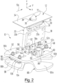
- Figure 1 10 is a total of a fastening device, with the help of which a vehicle body 12, which is only schematically and only partially indicated in the figures, can be releasably fastened to a skid 14, of which in turn only in Figure 1 only a frame section 16 can be seen.
- a skid, as used to convey vehicle bodies, is known, which is why a more detailed explanation of this can be dispensed with.
- the reference coordinate system shown is firmly anchored to the fastening device 10, so that it moves with the fastening device 10 in space.
- the directional information used below means the positive x-direction on the right, the positive y-direction at the front and the positive z-direction at the top. The directions on the left, behind and below therefore indicate the opposite direction.
- the fastening device 10 comprises a flange plate 18, by means of which it can be screwed to the frame section 16 of the skid 14, with corresponding screws in Figure 1 are not shown.
- the flange plate 18 carries a housing profile 20 which is U-shaped in cross section and has two opposite side walls 20a, 20b running in an xz plane and a longitudinal wall 20c running perpendicular to these and thus in a yz plane.
- the open side of the housing profile 20 points to the right towards the flange plate 18.
- the housing profile 20 On a first, upper end face 22, the housing profile 20 carries a first contact plate 24, which runs in an xy plane.
- the contact plate 24 can, for example, be welded to the housing profile 20.
- a second contact plate 26 is arranged which is parallel to it and is screwed to the first contact plate 24.
- the first and second contact plates 24, 26 are part of a contact element 28. Via this, the vehicle body 12 can be electrically contacted in order to coat the vehicle body 12 with paint, for example in an electrophoretic dip painting system.
- the contact element 28 also includes a fitting part 30, which is welded into a circular cross-sectional passage 32 of the external second contact plate 26.
- the surface contour of the fitting part 30 on its upper side remote from the housing profile 20 is complementary to the course of a coupling plate 34 of the vehicle body 12 to be fastened, which in particular has a circular passage 36 with a circumferential collar 38 projecting upwards at the edge of the passage 36, in which the fitting part 30 can engage precisely with a corresponding projection 39.
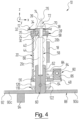
- the fitting part 30 has a circular cross-sectional passage 40, the longitudinal axis 42 of which is offset from the longitudinal axis of the passage 36 of the vehicle body 12 when its coupling plate 34 rests on the fitting part 30, as shown in Figure 4 is shown.
- the first coupling plate 24 has a passage 44 coaxial with the passage 40 in the fitting element 30, both passages 40, 44 also having the same cross section.
- a bearing plate 48 is welded, which runs parallel to the contact plates 24 and 26.
- the bearing plate 48 ends with a left outer edge 50 approximately with the outer surface of the longitudinal wall 20c of the housing profile 20, but otherwise extends to the right as well as to the front and rear beyond the housing profile 20.
- the bearing plate 48 In the areas next to the side walls 20a, 20b of the housing profile 20, the bearing plate 48 has two elongated holes 52a, 52b or 54a, 54b that run parallel to one another and perpendicular to the side walls 20a, 20b of the housing profile 20.
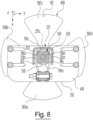
- the side walls 20a, 20b and the longitudinal wall 20c of the housing profile 20 surround a circular cross-sectional passage 56 of the bearing plate 48, the diameter of which corresponds approximately to the inner diameter of the housing profile 20, as in the Figures 4 and 8th can be recognized.
- the fastening device 10 also includes a shaft 58 which extends in the z direction and projects outwards through the passages 40, 44 of the coupling element 28 and the passage 56 of the bearing plate 48.
- the shaft 58 comprises a rotating block 60 designed as a square, which in turn comprises a holding section 62 which is arranged inside the housing profile 20 and a drive section 64 which projects outwards through the bearing plate 48.
- the longitudinal edges of the rotating block 60 touch the inner lateral surface of the passage 56 of the bearing plate 48. Due to the essentially square cross section of the rotating block 60 of the shaft 58, sticking of the shaft 58 in the bearing plate 48 by, for example, coating media can be largely avoided.
- a central shaft section 66 with a circular cross section is connected to the free upper end of the holding section 62 of the rotating block 60. At its upper end remote from the rotary block 60, this merges into a coupling section 68 of the shaft 58.
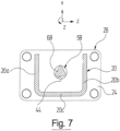
- the coupling section 68 is a triangle with a largely triangular cross section (see also Figure 7 ) is formed, the clear outer contour of which corresponds to that of the central shaft section 66.
- the coupling section 68 of the shaft 58 extends through the passages 40, 44 of the contact element 28, which have a diameter that corresponds to that of the central shaft section 66.
- the triangular cross section of the coupling section 68 of the shaft 58 can largely prevent it from sticking in the passages 40, 44 of the contact element 28, for example by coating media.
- the shaft 58 carries a clamping cone 72 as the actual fastening element, which tapers away from the shaft 58 in the longitudinal direction and whose largest diameter corresponds to the diameter of the projection 39 of the fitting part 30 and thus also of the passage 36 in the Vehicle body 12 is adapted so that it fits largely precisely through the corresponding passages can pass through.
- the rotary block 60, the middle shaft section 66 and the coupling section 68 of the shaft 58 are arranged coaxially to one another and specify the longitudinal or rotational axis 74 of the shaft 58.
- the clamping cone 72 is attached to the shaft 58 in such a way that its longitudinal axis 76 is arranged eccentrically relative to the axis of rotation 74 of the shaft 58 and offset in the direction of one of the longitudinal surfaces of the rotating block 60 of the shaft 58.
- This longitudinal surface of the rotating block 60 bears the reference number 78a and is in Figure 4 can be seen on the right, where it points to the right in the x direction towards the flange plate 18.
- the three further longitudinal surfaces of the rotary block 60 of the shaft 58 are marked with the reference numbers 78b, 78c and 78d, viewed downwards from the direction of the clamping cone 72, starting from the longitudinal surface 78a in a clockwise direction (see, for example, Figure 8 ).
- the holding section 62 of the rotating block 60 of the shaft 58 cooperates with a retaining device 80, by which the shaft 58 is secured against unintentional rotation.
- the retaining device 80 comprises two pairs of spring bars 82 and 84, respectively, the spring bars of each pair 82, 84 being arranged one above the other in the z-direction of the shaft 58 and resting on the holding section 62 of the rotating block 60 of the shaft 58 on two opposite sides.
- the pairs of spring bars 82, 84 are attached to a holding block 86 on the bearing plate 48 and protrude through the open side of the housing profile 20 into it.
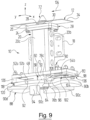
- the drive section 64 of the rotary block 60 of the shaft 58 carries at its free lower end a rotating star 88 with four driving tongues 90a, 90b, 90c, 90d extending radially outwards from the shaft 58 and in the direction of the shaft axis 74 Widen shaft 58 symmetrically.
- the central axis of the driving tongue 90a which is not specifically marked, runs perpendicular to the longitudinal surface 78a of the rotating block 60 of the shaft 58.
- the central axes of the driving tongues 90b, 90c and 90d which are also not specifically marked, run correspondingly perpendicular to the longitudinal surfaces 78b, 78c and 78d of the rotating block 60.
- the driving tongue 90c is designed as a position detection tongue and for this purpose has a central notch 92 on its outer edge and carries a position block 94 on its side remote from the shaft 58. Their position can be detected optically or mechanically in a manner known per se, from which the Rotational position of the shaft 58 and thus the position of the clamping cone 72 can be derived.
- the longitudinal surface 78b of the rotating block 60 of the shaft 58 carries an actuating element in the form of an actuating pin 96, which extends perpendicular to the longitudinal surface 78b.
- This actuating pin 96 works together with a locking device 98 and a release device 100, which are held in the elongated holes 52 and 54 on the underside of the bearing plate 48, which is remote from the housing profile 20.
- the locking device 98 comprises a spring plate 102 with a fastening end 104 and a locking end 106.
- the spring plate 102 has two parallel elongated holes 108a, 108b, which are complementary to the elongated holes 52a, 52b of the bearing plate 48.
- the spring plate 102 is arranged so that its elongated holes 108a, 108b largely overlap the elongated holes 52a, 52b of the bearing plate 48.
- the spring plate 102 is connected to the bearing plate 48 via a spacer 110 arranged between the spring plate 102 and the bearing plate 48 by means of screws that are not specifically referenced.
- the spring plate 102 extends so far in the direction of the rotating block 60 of the shaft 58 that the actuating pin 96 can come into contact with the locking end 106 of the spring plate 102.
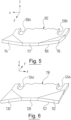
- the locking end 106 of the spring plate 102 has a central pressure section 112, which runs parallel to the bearing plate 48, and two guide corner sections 114, 116, which are inclined upwards towards the bearing plate 48.
- the locking end 106 of the spring plate 102 is in Figure 5 shown again on an enlarged scale.
- the guide corner sections 114, 116 thus flank the pressure section 112 in the direction of movement of the actuating pin 96, which will be explained further below.
- the release device 100 includes a rigid guide plate 118, which corresponds in structure to the spring plate 102 of the locking device 98. This has a fastening end 120 and a release end 122. Two parallel elongated holes 124a, 124b on the fastening end 120 of the guide plate 118 are complementary to the elongated holes 54a, 54b of the bearing plate 48.
- the guide plate 118 is arranged so that its elongated holes 124a, 124b overlap the elongated holes 54a, 54b of the bearing plate 48 largely congruently.
- the guide plate 118 is connected to the bearing plate 48 by means of screws that are not specifically referenced, with a spacer 126 being arranged between the guide plate 118 and the bearing plate 48.
- the guide plate 118 extends toward the rotation block 60 of the shaft 58 so far that the actuating pin 96 can come into contact with the release end 122 of the guide plate 118.
- the release end 122 of the guide plate 118 has a central holding portion 128 which extends parallel to the bearing plate 48 and two guide corner portions 130, 132 which slope downwardly away from the bearing plate 48.
- the release end 122 of the guide plate 102 is in Figure 6 shown again on an enlarged scale.
- the guide corner sections 130, 132 thus flank the pressure section 112 accordingly in the direction of movement of the actuating pin 96.
- the fastening device 10 described above works as follows:
- the skid 14 carries a fastening device 10 at four positions, the fastening and releasing process of a vehicle body 12 on the skid 14 being explained below only with regard to a fastening device 10.
- the shaft 58 assumes a rotational position in a first shaft position, in which the position detection tongue 90c of the rotating star 88 points forward in the y direction. In comparison to the rotational position of the shaft 58 shown in the figures, this is rotated by 180 ° in its first shaft position.
- the clamping cone 78 assumes a release position. In this it is aligned radially with the projection 39 of the fitting part 30 of the contact element 28 and is arranged coaxially therewith.
- the actuating pin 96 is arranged between the bearing plate 48 and the release end 122 of the guide plate 118 of the release device 100 and rests centrally on its holding section 128.
- the spacer 126 of the release device 100 is dimensioned such that the shaft 58 in its first shaft position assumes such an axial position that a distance remains between the clamping cone 72 and the fitting part 30 of the contact element 28, which also defines the release position of the clamping cone 72.
- a vehicle body 12 is applied to the skid 14, with the clamping cone 72 being guided through the passage 36 in the coupling plate 34 of the vehicle body 12.
- the conical design of the clamping cone 12 makes it easier to insert it into the passage 36 of the vehicle body 12.
- the vehicle body 12 then rests with the coupling plate 34 on the fitting part 30 of the contact element 28, the projection 39 of the fitting part 30 being surrounded by the collar 38 of the coupling plate 34, as shown in Figure 4 can be recognized.
- such a conveyor device includes adjustment bolts, not specifically shown here, at predetermined positions, with which the turnstile 88 of the fastening device 10 can work together.
- the turnstile 88 abuts against such a bolt with its driving tongues 90a, which is perpendicular to the transport direction 135 in the first shaft position of the shaft 58.
- the shaft 58 is thereby rotated from its first shaft position by 90° into a second shaft position.
- the transport direction 134 of the skid 14 should point forward in the y direction, for example, so that the shaft 58 is rotated clockwise when viewed from the direction of the clamping cone 72.
- the retaining force of the spring bars 82 and 84 of the retaining device 80 must be overcome every time the shaft 58 is rotated by 90 °, regardless of the direction. However, this will not be discussed further below.
- the actuating pin 96 runs down from the holding section 128 of the guide plate 118 over its guide corner section 132, so that the clamping cone 72 is no longer held in its release position.
- the actuating pin 96 now points to the right, i.e. in the x direction.
- the clamping cone 72 In the second shaft position of the shaft 58, the clamping cone 72 assumes a first intermediate position in which its longitudinal axis 76 is offset in the transport direction 134 or in the y direction relative to the shaft axis 74. In this intermediate position, it is no longer aligned with the projection 39 of the fitting part 30 of the contact element 28, but protrudes laterally above it and the collar 38 of the coupling plate 34 of the vehicle body 12.
- the vehicle body 12 is already secured by the clamping cone 72 in its first intermediate position against loosening from the fastening device 10 in the direction of the shaft axis 74.
- the shaft 58 still has a certain amount of freedom of movement in the direction of its longitudinal axis 74, as a result of which the vehicle body 12 can possibly detach somewhat from the fitting part 30, which in particular leads to an undesirable poorer contact between the vehicle body 12 and the contact element 28. Roughly speaking, the vehicle body 12 shakes on the fastening device 10.
- the clamping cone 72 is brought into a locking position.
- a second adjustment bolt is provided in the travel path of the skid 14, which ensures that the turnstile 88 and thus the shaft 58 are rotated from their second shaft position by a further 90 ° clockwise into a third shaft position during the further movement of the skid 14 in the transport direction 134 is in which the clamping cone 72 assumes its locking position.
- the spacer 110 of the locking device 98 is dimensioned such that the actuating pin 96 initially abuts against the lower surface of the guide corner section 114 of the spring plate 102, which is remote from the bearing plate 48, when the shaft 58 is rotated from its second shaft position to the third shaft position.
- the spacer 110 of the locking device 98 is thinner than the spacer 126 of the release device 100.
- the actuating pin 96 must now work against the spring force of the spring plate 102 until it finally rests against the pressure section 112 of the spring plate 102 on the side remote from the bearing plate 48, when the shaft 58 is in its third shaft position .
- the actuating pin 96 points backwards, i.e. in the opposite direction to the y-direction or transport direction 134. This is the position shown in the figures.
- the spring plate 102 is now bent slightly upwards and presses against the actuating pin 96 in such a way that the shaft 58 and thus also the clamping cone 72 are biased away from the vehicle body 12. The shaft 58 is thus pressed downward by the spring plate 102 in the direction opposite to the z-direction.
- the spring plate 102 in conjunction with the spacer 110 forms a pretensioning device 136, which presses the clamping cone 72 in the locking position under pretension against the coupling plate 34 of the vehicle body 12 in the direction of the contact element 28.
- the contact element 28 with the fitting part 30 thus serves as a counter element for the clamping cone 72.
- the coupling plate 34 which serves as a holding component of the vehicle body 12, is locked between the clamping cone 72 and the contact element 28.
- the effective spring force of the spring plate 102 and thus the strength of the preload can be adjusted by appropriately positioning the spacer 110 of the locking device 98.
- the skid 14 is again guided over two adjustment bolts which are present one behind the other in the travel path of the skid 14 and which rotate the turnstile 88 clockwise by 90° when viewed from the direction of the clamping cone 72.
- the actuating pin 96 is first moved from the pressure section 112 of the spring plate 102 to its in Figure 5 Guide corner section 116 that can be seen on the right is moved and guided over it.
- Guide corner section 116 that can be seen on the right is moved and guided over it.
- the bias of the clamping cone 72 against the contact element 28 is canceled and the attachment of the vehicle body 12 to the skid 14 is loosened.
- the shaft assumes a fourth shaft position and the clamping cone 72 assumes a second intermediate position, in which the actuating pin 96 points to the left.
- the clamping cone 72 must first be brought into its release position, for which the shaft 58 is once again rotated clockwise when viewed from the direction of the clamping cone 72.
- the actuating pin 96 first abuts against the surface of the guide corner section 130 of the guide plate 118 facing the bearing plate 48 and must follow the surface course of the release end 122 of the guide plate 118 as the shaft 58 rotates further.
- the shaft 58 is moved upwards in the z direction until the actuating pin 96 comes to rest on its holding section 128 between the bearing plate 48 and the guide plate 118.
- the shaft 58 returns to its first shaft position explained above and the clamping cone 72 assumes its release position.
- the vehicle body 12 can be removed from the fastening device 10 and thus from the skid 14 in the z direction.
- the shaft 58 moves approximately 3 mm to 7 mm in its longitudinal direction. In practice, a shaft stroke of around 5 mm has proven to be effective.
Landscapes
- Engineering & Computer Science (AREA)
- Mechanical Engineering (AREA)
- Manufacturing & Machinery (AREA)
- Chemical & Material Sciences (AREA)
- Combustion & Propulsion (AREA)
- Transportation (AREA)
- Automobile Manufacture Line, Endless Track Vehicle, Trailer (AREA)
- Clamps And Clips (AREA)
- Connection Of Plates (AREA)
Priority Applications (1)
| Application Number | Priority Date | Filing Date | Title |
|---|---|---|---|
| PL11700997.7T PL2525944T5 (pl) | 2010-01-21 | 2011-01-13 | Przyrząd blokujący do mocowania przedmiotu na strukturze nośnej i skid z takim przyrządem |
Applications Claiming Priority (2)
| Application Number | Priority Date | Filing Date | Title |
|---|---|---|---|
| DE102010005337A DE102010005337A1 (de) | 2010-01-21 | 2010-01-21 | Vorrichtung zum Befestigen eines Gegenstandes an einer Tragstruktur und Skid mit einer solchen Vorrichtung |
| PCT/EP2011/000116 WO2011088967A1 (de) | 2010-01-21 | 2011-01-13 | Verriegelungsvorrichtung zum befestigen eines gegenstandes an einer tragstruktur und skid mit einer solchen vorrichtung |
Publications (3)
| Publication Number | Publication Date |
|---|---|
| EP2525944A1 EP2525944A1 (de) | 2012-11-28 |
| EP2525944B1 EP2525944B1 (de) | 2020-12-02 |
| EP2525944B2 true EP2525944B2 (de) | 2023-12-27 |
Family
ID=43901009
Family Applications (1)
| Application Number | Title | Priority Date | Filing Date |
|---|---|---|---|
| EP11700997.7A Active EP2525944B2 (de) | 2010-01-21 | 2011-01-13 | Verriegelungsvorrichtung zum befestigen eines gegenstandes an einer tragstruktur und skid mit einer solchen vorrichtung |
Country Status (7)
| Country | Link |
|---|---|
| EP (1) | EP2525944B2 (pl) |
| JP (1) | JP5905831B2 (pl) |
| CN (1) | CN102712081B (pl) |
| DE (1) | DE102010005337A1 (pl) |
| ES (1) | ES2855010T5 (pl) |
| PL (1) | PL2525944T5 (pl) |
| WO (1) | WO2011088967A1 (pl) |
Families Citing this family (5)
| Publication number | Priority date | Publication date | Assignee | Title |
|---|---|---|---|---|
| CN102862793B (zh) * | 2012-09-27 | 2015-07-08 | 东风设计研究院有限公司 | 自动锁紧解锁装置 |
| DE102013100619A1 (de) | 2012-12-19 | 2014-06-26 | Dr. Ing. H.C. F. Porsche Aktiengesellschaft | Transportvorrichtung |
| DE102015212790A1 (de) * | 2015-07-08 | 2017-01-12 | Dürr Systems GmbH | Vorrichtung und Verfahren zum Fördern von Werkstücken |
| DE102017201792A1 (de) | 2017-02-06 | 2018-08-09 | Bayerische Motoren Werke Aktiengesellschaft | Abstützeinrichtung, Montagestation und Verfahren zum Herstellen eines Kraftfahrzeugs |
| CN113512748B (zh) * | 2021-06-24 | 2022-12-02 | 机械工业第九设计研究院股份有限公司 | 一种可夹紧滑橇支点 |
Citations (10)
| Publication number | Priority date | Publication date | Assignee | Title |
|---|---|---|---|---|
| JPH03256641A (ja) † | 1990-03-05 | 1991-11-15 | Honda Motor Co Ltd | ワークのチャック装置 |
| JP2000218457A (ja) † | 1999-02-04 | 2000-08-08 | Howa Mach Ltd | ワーク搬送用のパレット |
| JP2000246569A (ja) † | 1999-03-01 | 2000-09-12 | Taiyo Ltd | クランプ装置 |
| JP2002307256A (ja) † | 2001-04-12 | 2002-10-23 | Daihatsu Motor Co Ltd | クランプ装置 |
| JP2003145363A (ja) † | 2001-11-08 | 2003-05-20 | Daihatsu Motor Co Ltd | ワーク搬送台車 |
| JP2003145362A (ja) † | 2001-11-08 | 2003-05-20 | Daihatsu Motor Co Ltd | ワーク搬送台車 |
| JP2003159617A (ja) † | 2001-11-27 | 2003-06-03 | Koganei Corp | ワーククランプ装置およびワーククランプ装置を備えた搬送台車 |
| US20050017424A1 (en) † | 2003-07-24 | 2005-01-27 | Univer S.P.A. | Toggle-lever clamping device for clamping work pieces with self-compensation |
| JP2006272492A (ja) † | 2005-03-29 | 2006-10-12 | Nissan Motor Co Ltd | 部品組立方法と部品組立装置および部品組み立てに用いる脱着工具 |
| US7584946B2 (en) † | 2007-07-27 | 2009-09-08 | Koganei Corporation | Electric positioning and clamping apparatus |
Family Cites Families (12)
| Publication number | Priority date | Publication date | Assignee | Title |
|---|---|---|---|---|
| JPH056036Y2 (pl) * | 1987-12-24 | 1993-02-17 | ||
| FR2781176B1 (fr) * | 1998-07-20 | 2000-09-01 | Patrice Vouland | Pilote auto serrant |
| JP4328991B2 (ja) * | 1999-12-27 | 2009-09-09 | 株式会社パボット技研 | 電動ガイドピンクランプ |
| JP2002239864A (ja) * | 2001-02-16 | 2002-08-28 | Daihatsu Motor Co Ltd | 位置決めクランプ装置 |
| JP3962552B2 (ja) * | 2001-03-12 | 2007-08-22 | 日産自動車株式会社 | 車体搬送装置 |
| JP2002274451A (ja) * | 2001-03-21 | 2002-09-25 | Nissan Motor Co Ltd | 車体組立装置 |
| FR2832341B1 (fr) * | 2001-11-16 | 2004-03-19 | Fiam | Outil pilote de centrage et de serrage |
| JP3894815B2 (ja) * | 2002-03-20 | 2007-03-22 | 株式会社コガネイ | 位置決めクランプ装置 |
| JP4062315B2 (ja) * | 2004-04-12 | 2008-03-19 | 日産自動車株式会社 | 位置決めクランプ装置とそのスパッタ侵入防止方法 |
| US7370856B2 (en) * | 2005-10-04 | 2008-05-13 | Btm Corporation | Rotating head pin clamp |
| DE202006011130U1 (de) | 2006-05-22 | 2006-10-19 | Dürr Systems GmbH | Verriegelungsvorrichtung zum Verriegeln eines Werkstücks an einem Werkstückträger |
| DE202007012041U1 (de) * | 2007-03-22 | 2007-12-13 | Hammann, Klaus | Vorrichtung zur Verriegelung der Fahrzeugkarosse auf einem Lackierskid |
-
2010
- 2010-01-21 DE DE102010005337A patent/DE102010005337A1/de active Pending
-
2011
- 2011-01-13 ES ES11700997T patent/ES2855010T5/es active Active
- 2011-01-13 EP EP11700997.7A patent/EP2525944B2/de active Active
- 2011-01-13 PL PL11700997.7T patent/PL2525944T5/pl unknown
- 2011-01-13 JP JP2012549278A patent/JP5905831B2/ja active Active
- 2011-01-13 CN CN201180006668.1A patent/CN102712081B/zh active Active
- 2011-01-13 WO PCT/EP2011/000116 patent/WO2011088967A1/de not_active Ceased
Patent Citations (10)
| Publication number | Priority date | Publication date | Assignee | Title |
|---|---|---|---|---|
| JPH03256641A (ja) † | 1990-03-05 | 1991-11-15 | Honda Motor Co Ltd | ワークのチャック装置 |
| JP2000218457A (ja) † | 1999-02-04 | 2000-08-08 | Howa Mach Ltd | ワーク搬送用のパレット |
| JP2000246569A (ja) † | 1999-03-01 | 2000-09-12 | Taiyo Ltd | クランプ装置 |
| JP2002307256A (ja) † | 2001-04-12 | 2002-10-23 | Daihatsu Motor Co Ltd | クランプ装置 |
| JP2003145363A (ja) † | 2001-11-08 | 2003-05-20 | Daihatsu Motor Co Ltd | ワーク搬送台車 |
| JP2003145362A (ja) † | 2001-11-08 | 2003-05-20 | Daihatsu Motor Co Ltd | ワーク搬送台車 |
| JP2003159617A (ja) † | 2001-11-27 | 2003-06-03 | Koganei Corp | ワーククランプ装置およびワーククランプ装置を備えた搬送台車 |
| US20050017424A1 (en) † | 2003-07-24 | 2005-01-27 | Univer S.P.A. | Toggle-lever clamping device for clamping work pieces with self-compensation |
| JP2006272492A (ja) † | 2005-03-29 | 2006-10-12 | Nissan Motor Co Ltd | 部品組立方法と部品組立装置および部品組み立てに用いる脱着工具 |
| US7584946B2 (en) † | 2007-07-27 | 2009-09-08 | Koganei Corporation | Electric positioning and clamping apparatus |
Also Published As
| Publication number | Publication date |
|---|---|
| JP5905831B2 (ja) | 2016-04-20 |
| WO2011088967A1 (de) | 2011-07-28 |
| ES2855010T3 (es) | 2021-09-23 |
| CN102712081B (zh) | 2015-12-16 |
| CN102712081A (zh) | 2012-10-03 |
| EP2525944A1 (de) | 2012-11-28 |
| DE102010005337A1 (de) | 2011-07-28 |
| EP2525944B1 (de) | 2020-12-02 |
| JP2013517179A (ja) | 2013-05-16 |
| PL2525944T5 (pl) | 2024-04-08 |
| PL2525944T3 (pl) | 2021-06-28 |
| ES2855010T5 (es) | 2024-07-02 |
Similar Documents
| Publication | Publication Date | Title |
|---|---|---|
| AT510225B1 (de) | Transfer-fördervorrichtung | |
| EP2525944B2 (de) | Verriegelungsvorrichtung zum befestigen eines gegenstandes an einer tragstruktur und skid mit einer solchen vorrichtung | |
| EP1824763B1 (de) | Fördereinrichtung | |
| DE3205979A1 (de) | Lenkachse mit hilfskraftunterstuetzung und einstellbaren anschlaegen | |
| EP2716171B1 (de) | Aufnahmevorrichtung zur Aufnahme von Artikeln der Tabak verarbeitenden Industrie | |
| EP2570039B1 (de) | Fördervorrichtung zum Fördern von Artikeln der Tabak verarbeitenden Industrie sowie Verwendung eines Bauteil in einer solchen Vorrichtung | |
| EP2852363B1 (de) | Befestigungseinrichtung zum befestigen von zubehörteilen an medizinischen einrichtungen | |
| EP3715009B1 (de) | Verfahren zum herstellen von bewehrungsmatten | |
| DE102017210160B4 (de) | Transporteinrichtung, Transportsystem und Verfahren zum Transport von Gegenständen | |
| WO2007137629A1 (de) | Förderkette mit aufklappbarem greifköpf | |
| EP3858532A1 (de) | Elementzufuhrvorrichtung für ein setz-schweiss-gerät, ein elementnest und ein nachrüstsatz für das setz-schweiss-gerät sowie entsprechende zufuhrverfahren eines schweisshilfsfügeteils | |
| DE3104667A1 (de) | Ladeeinrichtung fuer metallrohlinge | |
| DE102017222853B4 (de) | Fördervorrichtung | |
| EP3666049B1 (de) | Klemmrahmen und transportvorrichtung zum transport von substraten | |
| EP2147875A2 (de) | Mitnehmer | |
| EP4175495B1 (de) | Transfervorrichtung und verfahren zum übergeben stabförmiger artikel von einer strangbildenden vorrichtung an eine trommelvorrichtung | |
| DE202022105673U1 (de) | Umlenkeinrichtung | |
| EP1541277B1 (de) | Positioniereinheit und Transportsystem mit Positioniereinrichtung | |
| EP2105270B1 (de) | Zuführeinrichtung für eine Bearbeitungsmaschine | |
| EP1522374B1 (de) | Bauteil-Transportvorrichtung | |
| EP3728005B1 (de) | Werkstückaufnahmevorrichtung zum fördern von werkstücken und fördervorrichtung mit solcher werkstückaufnahmevorrichtung | |
| EP2743159B1 (de) | Kotflügelerweiterung | |
| EP1522357B1 (de) | Elektrodenschliessmechanikvorrichtung | |
| EP1315618A1 (de) | Ein verfahren und vorrichtungen zum einziehen und übergeben eines anfanges einer bahn | |
| EP3123853B1 (de) | Pflückvorrichtung zum ernten von stängeligem erntegut |
Legal Events
| Date | Code | Title | Description |
|---|---|---|---|
| PUAI | Public reference made under article 153(3) epc to a published international application that has entered the european phase |
Free format text: ORIGINAL CODE: 0009012 |
|
| 17P | Request for examination filed |
Effective date: 20120707 |
|
| AK | Designated contracting states |
Kind code of ref document: A1 Designated state(s): AL AT BE BG CH CY CZ DE DK EE ES FI FR GB GR HR HU IE IS IT LI LT LU LV MC MK MT NL NO PL PT RO RS SE SI SK SM TR |
|
| DAX | Request for extension of the european patent (deleted) | ||
| RAP1 | Party data changed (applicant data changed or rights of an application transferred) |
Owner name: EISENMANN SE |
|
| STAA | Information on the status of an ep patent application or granted ep patent |
Free format text: STATUS: EXAMINATION IS IN PROGRESS |
|
| 17Q | First examination report despatched |
Effective date: 20161219 |
|
| GRAP | Despatch of communication of intention to grant a patent |
Free format text: ORIGINAL CODE: EPIDOSNIGR1 |
|
| STAA | Information on the status of an ep patent application or granted ep patent |
Free format text: STATUS: GRANT OF PATENT IS INTENDED |
|
| INTG | Intention to grant announced |
Effective date: 20190424 |
|
| 19U | Interruption of proceedings before grant |
Effective date: 20190731 |
|
| 19W | Proceedings resumed before grant after interruption of proceedings |
Effective date: 20200803 |
|
| GRAS | Grant fee paid |
Free format text: ORIGINAL CODE: EPIDOSNIGR3 |
|
| GRAA | (expected) grant |
Free format text: ORIGINAL CODE: 0009210 |
|
| STAA | Information on the status of an ep patent application or granted ep patent |
Free format text: STATUS: THE PATENT HAS BEEN GRANTED |
|
| AK | Designated contracting states |
Kind code of ref document: B1 Designated state(s): AL AT BE BG CH CY CZ DE DK EE ES FI FR GB GR HR HU IE IS IT LI LT LU LV MC MK MT NL NO PL PT RO RS SE SI SK SM TR |
|
| REG | Reference to a national code |
Ref country code: GB Ref legal event code: FG4D Free format text: NOT ENGLISH |
|
| REG | Reference to a national code |
Ref country code: AT Ref legal event code: REF Ref document number: 1340379 Country of ref document: AT Kind code of ref document: T Effective date: 20201215 Ref country code: CH Ref legal event code: EP |
|
| REG | Reference to a national code |
Ref country code: IE Ref legal event code: FG4D Free format text: LANGUAGE OF EP DOCUMENT: GERMAN |
|
| REG | Reference to a national code |
Ref country code: DE Ref legal event code: R096 Ref document number: 502011016994 Country of ref document: DE |
|
| PG25 | Lapsed in a contracting state [announced via postgrant information from national office to epo] |
Ref country code: FI Free format text: LAPSE BECAUSE OF FAILURE TO SUBMIT A TRANSLATION OF THE DESCRIPTION OR TO PAY THE FEE WITHIN THE PRESCRIBED TIME-LIMIT Effective date: 20201202 Ref country code: RS Free format text: LAPSE BECAUSE OF FAILURE TO SUBMIT A TRANSLATION OF THE DESCRIPTION OR TO PAY THE FEE WITHIN THE PRESCRIBED TIME-LIMIT Effective date: 20201202 Ref country code: NO Free format text: LAPSE BECAUSE OF FAILURE TO SUBMIT A TRANSLATION OF THE DESCRIPTION OR TO PAY THE FEE WITHIN THE PRESCRIBED TIME-LIMIT Effective date: 20210302 Ref country code: GR Free format text: LAPSE BECAUSE OF FAILURE TO SUBMIT A TRANSLATION OF THE DESCRIPTION OR TO PAY THE FEE WITHIN THE PRESCRIBED TIME-LIMIT Effective date: 20210303 |
|
| REG | Reference to a national code |
Ref country code: NL Ref legal event code: MP Effective date: 20201202 |
|
| PG25 | Lapsed in a contracting state [announced via postgrant information from national office to epo] |
Ref country code: SE Free format text: LAPSE BECAUSE OF FAILURE TO SUBMIT A TRANSLATION OF THE DESCRIPTION OR TO PAY THE FEE WITHIN THE PRESCRIBED TIME-LIMIT Effective date: 20201202 Ref country code: LV Free format text: LAPSE BECAUSE OF FAILURE TO SUBMIT A TRANSLATION OF THE DESCRIPTION OR TO PAY THE FEE WITHIN THE PRESCRIBED TIME-LIMIT Effective date: 20201202 Ref country code: BG Free format text: LAPSE BECAUSE OF FAILURE TO SUBMIT A TRANSLATION OF THE DESCRIPTION OR TO PAY THE FEE WITHIN THE PRESCRIBED TIME-LIMIT Effective date: 20210302 |
|
| PG25 | Lapsed in a contracting state [announced via postgrant information from national office to epo] |
Ref country code: HR Free format text: LAPSE BECAUSE OF FAILURE TO SUBMIT A TRANSLATION OF THE DESCRIPTION OR TO PAY THE FEE WITHIN THE PRESCRIBED TIME-LIMIT Effective date: 20201202 Ref country code: NL Free format text: LAPSE BECAUSE OF FAILURE TO SUBMIT A TRANSLATION OF THE DESCRIPTION OR TO PAY THE FEE WITHIN THE PRESCRIBED TIME-LIMIT Effective date: 20201202 |
|
| REG | Reference to a national code |
Ref country code: LT Ref legal event code: MG9D |
|
| PG25 | Lapsed in a contracting state [announced via postgrant information from national office to epo] |
Ref country code: SK Free format text: LAPSE BECAUSE OF FAILURE TO SUBMIT A TRANSLATION OF THE DESCRIPTION OR TO PAY THE FEE WITHIN THE PRESCRIBED TIME-LIMIT Effective date: 20201202 Ref country code: RO Free format text: LAPSE BECAUSE OF FAILURE TO SUBMIT A TRANSLATION OF THE DESCRIPTION OR TO PAY THE FEE WITHIN THE PRESCRIBED TIME-LIMIT Effective date: 20201202 Ref country code: PT Free format text: LAPSE BECAUSE OF FAILURE TO SUBMIT A TRANSLATION OF THE DESCRIPTION OR TO PAY THE FEE WITHIN THE PRESCRIBED TIME-LIMIT Effective date: 20210405 Ref country code: LT Free format text: LAPSE BECAUSE OF FAILURE TO SUBMIT A TRANSLATION OF THE DESCRIPTION OR TO PAY THE FEE WITHIN THE PRESCRIBED TIME-LIMIT Effective date: 20201202 Ref country code: SM Free format text: LAPSE BECAUSE OF FAILURE TO SUBMIT A TRANSLATION OF THE DESCRIPTION OR TO PAY THE FEE WITHIN THE PRESCRIBED TIME-LIMIT Effective date: 20201202 Ref country code: EE Free format text: LAPSE BECAUSE OF FAILURE TO SUBMIT A TRANSLATION OF THE DESCRIPTION OR TO PAY THE FEE WITHIN THE PRESCRIBED TIME-LIMIT Effective date: 20201202 Ref country code: CZ Free format text: LAPSE BECAUSE OF FAILURE TO SUBMIT A TRANSLATION OF THE DESCRIPTION OR TO PAY THE FEE WITHIN THE PRESCRIBED TIME-LIMIT Effective date: 20201202 |
|
| REG | Reference to a national code |
Ref country code: CH Ref legal event code: PL |
|
| REG | Reference to a national code |
Ref country code: DE Ref legal event code: R026 Ref document number: 502011016994 Country of ref document: DE |
|
| PLBI | Opposition filed |
Free format text: ORIGINAL CODE: 0009260 |
|
| REG | Reference to a national code |
Ref country code: DE Ref legal event code: R081 Ref document number: 502011016994 Country of ref document: DE Owner name: EISENMANN GMBH, DE Free format text: FORMER OWNER: EISENMANN SE, 71032 BOEBLINGEN, DE |
|
| REG | Reference to a national code |
Ref country code: ES Ref legal event code: FG2A Ref document number: 2855010 Country of ref document: ES Kind code of ref document: T3 Effective date: 20210923 |
|
| PG25 | Lapsed in a contracting state [announced via postgrant information from national office to epo] |
Ref country code: LU Free format text: LAPSE BECAUSE OF NON-PAYMENT OF DUE FEES Effective date: 20210113 Ref country code: IS Free format text: LAPSE BECAUSE OF FAILURE TO SUBMIT A TRANSLATION OF THE DESCRIPTION OR TO PAY THE FEE WITHIN THE PRESCRIBED TIME-LIMIT Effective date: 20210402 Ref country code: MC Free format text: LAPSE BECAUSE OF FAILURE TO SUBMIT A TRANSLATION OF THE DESCRIPTION OR TO PAY THE FEE WITHIN THE PRESCRIBED TIME-LIMIT Effective date: 20201202 |
|
| 26 | Opposition filed |
Opponent name: DUERR SYSTEMS AG Effective date: 20210901 |
|
| PLAX | Notice of opposition and request to file observation + time limit sent |
Free format text: ORIGINAL CODE: EPIDOSNOBS2 |
|
| REG | Reference to a national code |
Ref country code: BE Ref legal event code: MM Effective date: 20210131 |
|
| PG25 | Lapsed in a contracting state [announced via postgrant information from national office to epo] |
Ref country code: FR Free format text: LAPSE BECAUSE OF NON-PAYMENT OF DUE FEES Effective date: 20210202 Ref country code: AL Free format text: LAPSE BECAUSE OF FAILURE TO SUBMIT A TRANSLATION OF THE DESCRIPTION OR TO PAY THE FEE WITHIN THE PRESCRIBED TIME-LIMIT Effective date: 20201202 |
|
| GBPC | Gb: european patent ceased through non-payment of renewal fee |
Effective date: 20210302 |
|
| PG25 | Lapsed in a contracting state [announced via postgrant information from national office to epo] |
Ref country code: LI Free format text: LAPSE BECAUSE OF NON-PAYMENT OF DUE FEES Effective date: 20210131 Ref country code: SI Free format text: LAPSE BECAUSE OF FAILURE TO SUBMIT A TRANSLATION OF THE DESCRIPTION OR TO PAY THE FEE WITHIN THE PRESCRIBED TIME-LIMIT Effective date: 20201202 Ref country code: CH Free format text: LAPSE BECAUSE OF NON-PAYMENT OF DUE FEES Effective date: 20210131 Ref country code: DK Free format text: LAPSE BECAUSE OF FAILURE TO SUBMIT A TRANSLATION OF THE DESCRIPTION OR TO PAY THE FEE WITHIN THE PRESCRIBED TIME-LIMIT Effective date: 20201202 |
|
| PLAB | Opposition data, opponent's data or that of the opponent's representative modified |
Free format text: ORIGINAL CODE: 0009299OPPO |
|
| PG25 | Lapsed in a contracting state [announced via postgrant information from national office to epo] |
Ref country code: IE Free format text: LAPSE BECAUSE OF NON-PAYMENT OF DUE FEES Effective date: 20210113 Ref country code: GB Free format text: LAPSE BECAUSE OF NON-PAYMENT OF DUE FEES Effective date: 20210302 |
|
| PLBB | Reply of patent proprietor to notice(s) of opposition received |
Free format text: ORIGINAL CODE: EPIDOSNOBS3 |
|
| R26 | Opposition filed (corrected) |
Opponent name: DUERR SYSTEMS AG Effective date: 20210901 |
|
| REG | Reference to a national code |
Ref country code: AT Ref legal event code: MM01 Ref document number: 1340379 Country of ref document: AT Kind code of ref document: T Effective date: 20210113 |
|
| RAP2 | Party data changed (patent owner data changed or rights of a patent transferred) |
Owner name: EISENMANN GMBH |
|
| PG25 | Lapsed in a contracting state [announced via postgrant information from national office to epo] |
Ref country code: AT Free format text: LAPSE BECAUSE OF NON-PAYMENT OF DUE FEES Effective date: 20210113 |
|
| PG25 | Lapsed in a contracting state [announced via postgrant information from national office to epo] |
Ref country code: IS Free format text: LAPSE BECAUSE OF FAILURE TO SUBMIT A TRANSLATION OF THE DESCRIPTION OR TO PAY THE FEE WITHIN THE PRESCRIBED TIME-LIMIT Effective date: 20210402 |
|
| REG | Reference to a national code |
Ref country code: ES Ref legal event code: PC2A Owner name: EISENMANN GMBH Effective date: 20220711 |
|
| PG25 | Lapsed in a contracting state [announced via postgrant information from national office to epo] |
Ref country code: BE Free format text: LAPSE BECAUSE OF NON-PAYMENT OF DUE FEES Effective date: 20210131 |
|
| PLAB | Opposition data, opponent's data or that of the opponent's representative modified |
Free format text: ORIGINAL CODE: 0009299OPPO |
|
| R26 | Opposition filed (corrected) |
Opponent name: DUERR SYSTEMS AG Effective date: 20210901 |
|
| PG25 | Lapsed in a contracting state [announced via postgrant information from national office to epo] |
Ref country code: HU Free format text: LAPSE BECAUSE OF FAILURE TO SUBMIT A TRANSLATION OF THE DESCRIPTION OR TO PAY THE FEE WITHIN THE PRESCRIBED TIME-LIMIT; INVALID AB INITIO Effective date: 20110113 Ref country code: CY Free format text: LAPSE BECAUSE OF FAILURE TO SUBMIT A TRANSLATION OF THE DESCRIPTION OR TO PAY THE FEE WITHIN THE PRESCRIBED TIME-LIMIT Effective date: 20201202 |
|
| P01 | Opt-out of the competence of the unified patent court (upc) registered |
Effective date: 20230529 |
|
| APAH | Appeal reference modified |
Free format text: ORIGINAL CODE: EPIDOSCREFNO |
|
| APBM | Appeal reference recorded |
Free format text: ORIGINAL CODE: EPIDOSNREFNO |
|
| APBP | Date of receipt of notice of appeal recorded |
Free format text: ORIGINAL CODE: EPIDOSNNOA2O |
|
| APBU | Appeal procedure closed |
Free format text: ORIGINAL CODE: EPIDOSNNOA9O |
|
| PUAH | Patent maintained in amended form |
Free format text: ORIGINAL CODE: 0009272 |
|
| STAA | Information on the status of an ep patent application or granted ep patent |
Free format text: STATUS: PATENT MAINTAINED AS AMENDED |
|
| 27A | Patent maintained in amended form |
Effective date: 20231227 |
|
| AK | Designated contracting states |
Kind code of ref document: B2 Designated state(s): AL AT BE BG CH CY CZ DE DK EE ES FI FR GB GR HR HU IE IS IT LI LT LU LV MC MK MT NL NO PL PT RO RS SE SI SK SM TR |
|
| REG | Reference to a national code |
Ref country code: DE Ref legal event code: R102 Ref document number: 502011016994 Country of ref document: DE |
|
| PG25 | Lapsed in a contracting state [announced via postgrant information from national office to epo] |
Ref country code: MK Free format text: LAPSE BECAUSE OF FAILURE TO SUBMIT A TRANSLATION OF THE DESCRIPTION OR TO PAY THE FEE WITHIN THE PRESCRIBED TIME-LIMIT Effective date: 20201202 |
|
| PG25 | Lapsed in a contracting state [announced via postgrant information from national office to epo] |
Ref country code: TR Free format text: LAPSE BECAUSE OF FAILURE TO SUBMIT A TRANSLATION OF THE DESCRIPTION OR TO PAY THE FEE WITHIN THE PRESCRIBED TIME-LIMIT Effective date: 20201202 |
|
| REG | Reference to a national code |
Ref country code: ES Ref legal event code: DC2A Ref document number: 2855010 Country of ref document: ES Kind code of ref document: T5 Effective date: 20240702 |
|
| PG25 | Lapsed in a contracting state [announced via postgrant information from national office to epo] |
Ref country code: MT Free format text: LAPSE BECAUSE OF FAILURE TO SUBMIT A TRANSLATION OF THE DESCRIPTION OR TO PAY THE FEE WITHIN THE PRESCRIBED TIME-LIMIT Effective date: 20201202 |
|
| PGFP | Annual fee paid to national office [announced via postgrant information from national office to epo] |
Ref country code: PL Payment date: 20251212 Year of fee payment: 16 |
|
| PGFP | Annual fee paid to national office [announced via postgrant information from national office to epo] |
Ref country code: ES Payment date: 20260217 Year of fee payment: 16 |
|
| PGFP | Annual fee paid to national office [announced via postgrant information from national office to epo] |
Ref country code: DE Payment date: 20260121 Year of fee payment: 16 |
|
| PGFP | Annual fee paid to national office [announced via postgrant information from national office to epo] |
Ref country code: IT Payment date: 20260130 Year of fee payment: 16 |