EP2520525B1 - Verfahren zur Herstellung von Stangen aus Druckprodukten - Google Patents
Verfahren zur Herstellung von Stangen aus Druckprodukten Download PDFInfo
- Publication number
- EP2520525B1 EP2520525B1 EP12165901.5A EP12165901A EP2520525B1 EP 2520525 B1 EP2520525 B1 EP 2520525B1 EP 12165901 A EP12165901 A EP 12165901A EP 2520525 B1 EP2520525 B1 EP 2520525B1
- Authority
- EP
- European Patent Office
- Prior art keywords
- book
- bundle
- book block
- printed sheets
- side edge
- Prior art date
- Legal status (The legal status is an assumption and is not a legal conclusion. Google has not performed a legal analysis and makes no representation as to the accuracy of the status listed.)
- Active
Links
Images

Classifications
-
- B—PERFORMING OPERATIONS; TRANSPORTING
- B65—CONVEYING; PACKING; STORING; HANDLING THIN OR FILAMENTARY MATERIAL
- B65H—HANDLING THIN OR FILAMENTARY MATERIAL, e.g. SHEETS, WEBS, CABLES
- B65H31/00—Pile receivers
- B65H31/04—Pile receivers with movable end support arranged to recede as pile accumulates
- B65H31/06—Pile receivers with movable end support arranged to recede as pile accumulates the articles being piled on edge
-
- B—PERFORMING OPERATIONS; TRANSPORTING
- B65—CONVEYING; PACKING; STORING; HANDLING THIN OR FILAMENTARY MATERIAL
- B65B—MACHINES, APPARATUS OR DEVICES FOR, OR METHODS OF, PACKAGING ARTICLES OR MATERIALS; UNPACKING
- B65B61/00—Auxiliary devices, not otherwise provided for, for operating on sheets, blanks, webs, binding material, containers or packages
- B65B61/24—Auxiliary devices, not otherwise provided for, for operating on sheets, blanks, webs, binding material, containers or packages for shaping or reshaping completed packages
-
- B—PERFORMING OPERATIONS; TRANSPORTING
- B65—CONVEYING; PACKING; STORING; HANDLING THIN OR FILAMENTARY MATERIAL
- B65B—MACHINES, APPARATUS OR DEVICES FOR, OR METHODS OF, PACKAGING ARTICLES OR MATERIALS; UNPACKING
- B65B61/00—Auxiliary devices, not otherwise provided for, for operating on sheets, blanks, webs, binding material, containers or packages
- B65B61/26—Auxiliary devices, not otherwise provided for, for operating on sheets, blanks, webs, binding material, containers or packages for marking or coding completed packages
-
- B—PERFORMING OPERATIONS; TRANSPORTING
- B65—CONVEYING; PACKING; STORING; HANDLING THIN OR FILAMENTARY MATERIAL
- B65H—HANDLING THIN OR FILAMENTARY MATERIAL, e.g. SHEETS, WEBS, CABLES
- B65H33/00—Forming counted batches in delivery pile or stream of articles
- B65H33/06—Forming counted batches in delivery pile or stream of articles by displacing articles to define batches
- B65H33/08—Displacing whole batches, e.g. forming stepped piles
-
- B—PERFORMING OPERATIONS; TRANSPORTING
- B65—CONVEYING; PACKING; STORING; HANDLING THIN OR FILAMENTARY MATERIAL
- B65H—HANDLING THIN OR FILAMENTARY MATERIAL, e.g. SHEETS, WEBS, CABLES
- B65H33/00—Forming counted batches in delivery pile or stream of articles
- B65H33/06—Forming counted batches in delivery pile or stream of articles by displacing articles to define batches
- B65H33/10—Displacing the end articles of a batch
-
- B—PERFORMING OPERATIONS; TRANSPORTING
- B65—CONVEYING; PACKING; STORING; HANDLING THIN OR FILAMENTARY MATERIAL
- B65H—HANDLING THIN OR FILAMENTARY MATERIAL, e.g. SHEETS, WEBS, CABLES
- B65H45/00—Folding thin material
- B65H45/12—Folding articles or webs with application of pressure to define or form crease lines
- B65H45/18—Oscillating or reciprocating blade folders
-
- B—PERFORMING OPERATIONS; TRANSPORTING
- B65—CONVEYING; PACKING; STORING; HANDLING THIN OR FILAMENTARY MATERIAL
- B65H—HANDLING THIN OR FILAMENTARY MATERIAL, e.g. SHEETS, WEBS, CABLES
- B65H2301/00—Handling processes for sheets or webs
- B65H2301/40—Type of handling process
- B65H2301/42—Piling, depiling, handling piles
- B65H2301/421—Forming a pile
- B65H2301/4214—Forming a pile of articles on edge
- B65H2301/42146—Forming a pile of articles on edge by introducing articles from above
-
- B—PERFORMING OPERATIONS; TRANSPORTING
- B65—CONVEYING; PACKING; STORING; HANDLING THIN OR FILAMENTARY MATERIAL
- B65H—HANDLING THIN OR FILAMENTARY MATERIAL, e.g. SHEETS, WEBS, CABLES
- B65H2301/00—Handling processes for sheets or webs
- B65H2301/40—Type of handling process
- B65H2301/42—Piling, depiling, handling piles
- B65H2301/421—Forming a pile
- B65H2301/4219—Forming a pile forming a pile in which articles are offset from each other, e.g. forming stepped pile
- B65H2301/42192—Forming a pile forming a pile in which articles are offset from each other, e.g. forming stepped pile forming a pile of articles in zigzag fashion
-
- B—PERFORMING OPERATIONS; TRANSPORTING
- B65—CONVEYING; PACKING; STORING; HANDLING THIN OR FILAMENTARY MATERIAL
- B65H—HANDLING THIN OR FILAMENTARY MATERIAL, e.g. SHEETS, WEBS, CABLES
- B65H2301/00—Handling processes for sheets or webs
- B65H2301/40—Type of handling process
- B65H2301/42—Piling, depiling, handling piles
- B65H2301/426—Forming batches
- B65H2301/4263—Feeding end plate or end sheet before formation or after completion of a pile
-
- B—PERFORMING OPERATIONS; TRANSPORTING
- B65—CONVEYING; PACKING; STORING; HANDLING THIN OR FILAMENTARY MATERIAL
- B65H—HANDLING THIN OR FILAMENTARY MATERIAL, e.g. SHEETS, WEBS, CABLES
- B65H2301/00—Handling processes for sheets or webs
- B65H2301/40—Type of handling process
- B65H2301/45—Folding, unfolding
Definitions
- the invention relates to a rod and a method for producing this rod, in which a plurality of printed sheets combined to form a book block and several book blocks with the same orientation each lower edges of the sheet together to form a bar and pressed, with two adjacent book block before pressing against each other offset and fixed after pressing in their position.
- Such rods are produced for intermediate storage of printed sheets by means of so-called rod jib.
- rod jib stand-together printed sheets are formed forming a rod, pressed together and strapped.
- the required printed sheets and envelopes are known to be printed and stored in any order in a first step.
- the printed sheets which can besispielmik be folded sheets or sheets with glued attachment sheet, collected in the correct order to loose book block and supplemented with other book parts, such as covers for hardcover products, attachment sheet, combined attachment sheets or envelopes and fed to a perfect binder where they are tied in the back and glued with the envelope or MahlzelstMail.
- both are processes feasible with the optimal speed corresponding to them.
- the disadvantage is that the binding process can only be carried out when all printed sheets and envelopes are printed, which requires a relatively large stock of printed sheets and envelopes.
- Next printing presses are known to successively print all the pages of a book and then provide complete, loose book block that can be fed directly to an adhesive binder. From the US3518940A Such a printing press is known. With this method, which is rarely used in practice, it is possible to avoid the temporary storage of printed signatures, which requires a very complex printing press. Moreover, this method is economical only for very long runs and the achievable print quality is low.
- digital printing machines which also successively print all pages of a book and then deliver complete, loose book blocks that can be bound without further operations. Accordingly, with a digital press, it is possible to optionally produce complete book blocks with different contents one after the other.
- Another advantage of digital printing machines is that no printing plates are needed. In addition to avoiding the costs incurred for the production of the printing plates, also eliminates the necessary for the printing plate changes business interruptions.
- the book block forming sheet or single sheets are designed as a stack and stored, for example, offset on a pallet to each other, so that they are later manually separated from each other in a simple manner. Alternatively, full-surface layers of book blocks can be formed, which are separated from each other by an intermediate layer. Such stacked book blocks can be stored for any length before they are fed to a perfect binder.
- the laying of loose stacks on pallets can be carried out automatically or manually with a so-called palletizer.
- a so-called palletizer Such a device is in the EP2098465 A1 disclosed.
- the loose sheet stacks of horizontal printed products are later removed manually from the pallet and inserted into the feed area of an adhesive binder.
- a disadvantage of this solution is known that the loose book block are pressed too little in the seams, making thick products in the fold substantially thicker than in the flat part.
- the lower book blocks are pressed the strongest and the top not at all. Poor or differently pressed book blocks can lead to serious problems in further processing or impede further processing.
- the EP1950159 A1 discloses a stacked array of flat printed products where the printed products in the stack are all aligned identically.
- One of the four sides of the printed products is thicker than the others because, for example, the printed products on that side have a fold or even a staple. So that these stacks are just as stable as those stacks which are formed of partial stacks alternately offset by 180 °, here the stacks of stacks are offset alternately to one another transversely to the thicker side.
- the partial stacks are offset perpendicular to the lower edges in the direction of the height of the stack. Trays designed in this way have the disadvantage that the printed products within the stack are pressed to different extents in the region of the thicker side, whereby the non-pressed seam areas tend to fan out.
- the invention has for its object to provide a method with which formed from gathered sheet blank loose book blocks and after the intermediate storage are again clearly separated from each other. It is a further object of the invention that the book blocks are pressed during the interim storage with a defined force.
- the object is achieved according to the invention in that loose book blocks are brought together to form rods, wherein a book block is offset parallel to the lower edges of the printed sheets and transversely to a height of the rod to be formed, a side edge of the book block protrudes from a side edge of an adjacent book block.
- the lateral offset of book block to book block which forms by this method within the resulting rod, creating clear separation points, which later allow to separate the loose book blocks safely from each other. Only by such a storage of the book block in the form of a rod can be ensured that all book blocks and printed sheets are pressed with the same force and that no deformations of individual book block occur until the removal of the book block at a later date, for example shortly before further processing.
- the book blocks are collected in such a way that the rod is formed such that folding edges of the printed sheets are used as bottom edges.
- the last in the course of the folding process resulting folding edge which is referred to as "last folding edge” is used as the lower edge, since the mechanical strength is highest.
- the n book blocks can be formed from at least one first and one last book block part of the same format and the book block parts each have a side edge on both sides of the bar to be formed.
- the side edge of the last book block part of a book block is alternately offset laterally relative to the side edge of the first book block part of an adjacent book block on a first or a second side of the rod to be formed or on both sides.
- the book blocks of the rod can each be formed from printed sheets with different print contents.
- the printed sheets of a digital printing machine which can optionally produce successively complete book blocks with different contents.
- rods can be made from book block in which several sheets are combined to form a book block and several book blocks are pressed with the same orientation each lower edge of the sheet standing to a rod.
- Each two adjacent book blocks are offset from each other and fixed in position.
- a book block is offset parallel to the lower edges of the signatures and transversely to a height of the bar such that one side edge of the at least one book block protrudes from a side edge of an adjacent book block.
- folding edges of the printed sheets in the bar form the lower edges.
- the book blocks are formed from at least a first and a last book block part of the same format and the book block parts each have a side edge.
- the side edge of the last book block part of a book block is alternately offset laterally relative to the side edge of the first book block part of an adjacent book block on a first or a second side of the bar or on both sides.
- the book blocks of the rod are each formed of printed sheets that have been printed for example by a digital press with different print contents
- the book blocks of the rod can each have a different print content.
- the printed sheets and / or the book blocks and / or the rods have at least one information carrier for their identification.
- each individual bar or its components can be assigned, for example, an individual processing.
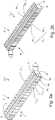
- the Fig. 1 shows an embodiment of a bar former 6 with upstream printing machine 4.
- the printing machine 4 for example, a digital printing machine, printed on a unwound from a paper roll 39 paper web, which is cut into sections 40 after printing. These sections 40, also called signature, can be designed either as folded in a folding device 37 or as unfolded printed sheet 10 in a scale flow 11.
- the printed sheets 10 have a lower edge 7, which may be a folded edge 5, as in Fig. 1a shown.
- the book blocks 3 1... N thus formed have two side edges 17 1 .
- the folding device 37 is in Fig. 1 illustrated as sword folder, in which the sections 40 are conveyed by means of a sword between two folding rollers and folded by them.
- the end of the conveying path of the sections 40 in front of the folding device 37 can be selected by means of a stop 41 which can be adjusted in the direction U.
- a stop 41 By cyclically adjusting the stop 41 can be transverse to a conveying direction F offset sub-shed 12 form. If the stop 41 is adjusted alternately after every last section 40 of a book block 3 1...
- Subsheds 12 offset transversely to the conveying direction F are formed, which are alternately offset to the left and right in the conveying direction F, corresponding to the content of a book block 3 and which are further conveyed with a scale flow conveyor 38 in the conveying direction F.
- portions 40 may be conveyed transversely directly away from the stop to form a scale flow 11.
- the formation of stacks of sections 40 can take place, these subsequently being converted into a shingled stream 11.
- other book parts 20 such as, in particular, book covers for hardcover products, attachment sheets, combined attachment sheets or envelopes, can also be arranged.
- the shingled stream 11 is piled up in the bar former 6 into a bar 13 with a height H ( Fig. 2b ), provided with end boards 14, pressed with an adjustable force and strapped with a tension element 15. Due to the offset of the partial shed 12 to each other, the book blocks 3 1 ... n stacked in the rod 13 are also staggered. In the strapped rods 13, the pressing force is maintained, whereby all contained in the bars 13 sheet 10 remain pressed with the same force. By squeezing the spring-back of the book block 3 1 ... n in the region of the folds when loosening the tension element 15 can be significantly reduced, which during a further processing of the book block 3 1 ... n higher product quality can be achieved because no deformation of the book blocks 3 1 ... n more occur. As rod-forming 6, for example, the generic device to EP623542 A1 be used. A slider 16 then pushes the strapped rod 13 in the sliding direction S on, for example, a buffer device.
- rods 13 For pressing and stabilizing the rods 13 other devices are also conceivable instead of end boards 14 and tension members 15.
- the rods 13 could be held together and pressed by means of reusable clips, which clips could be automatically or manually returned to the rod former 6 after opening.
- the Fig. 2a shows the basic structure of a rod 13 of book block 3 1 ... n , in which several printed sheets 10 (FIG. Fig. 1 ) are combined to form a book block 3 1... n and a plurality of book blocks 3 1... n with the same orientation in each case on lower edges 7 (FIG. Fig. 1 ) of the sheet 10 are pressed down standing to a rod 13.
- Each two adjacent book blocks 3 1 ... n are offset from each other and fixed in position, with a book block 3 1 ... n parallel to the lower edges 7 of the sheet 10 (FIG. Fig. 1 ) and transverse to a height H of the rod 13 is offset such that a side edge 17 1 ... n at least one book block 3 1 ...
- 13 information carriers 19 1 , 19 2 , 19 3 are shown here within the rod 13, which serve to identify the printed sheets 10 and / or the book blocks 3 1... N and / or the rods 13, depending on where they are mounted.
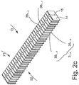
- FIG. 2b and 2c Further embodiments of a rod 13 are in the Fig. 2b and 2c shown.
- the book blocks 3 1... N are formed from at least one first and one last book block part 35 1... N of the same format, and the book block parts 35 1... N each have a side edge 36 1 Side edge 36 1 ... n of the last book block part 35 1 ... n of a book block 3 1 ... n respectively opposite the side edge 36 1 ... n of the first book block part 35 1 ... n of an adjacent book block 3 1 .. n. .n on a first or a second side 21, 22 of the rod 13 (FIG. Fig. 2b ) or alternating on both sides 21, 22 ( Fig. 2c ) is offset laterally.
Landscapes
- Engineering & Computer Science (AREA)
- Mechanical Engineering (AREA)
- Folding Of Thin Sheet-Like Materials, Special Discharging Devices, And Others (AREA)
- Forming Counted Batches (AREA)
- Pile Receivers (AREA)
Description
- Die Erfindung betrifft eine Stange und ein Verfahren zur Herstellung dieser Stange, bei dem mehrere Druckbogen zu einem Buchblock zusammengefasst und mehrere Buchblocks mit gleicher Orientierung jeweils auf Unterkanten der Druckbogen stehend zu einer Stange zusammengeführt und abgepresst werden, wobei jeweils zwei benachbarte Buchblocks vor dem Abpressen gegeneinander versetzt und nach dem Abpressen in ihrer Position fixiert werden. Derartige Stangen werden zur Zwischenlagerung von Druckbogen mittels sogenannter Stangenausleger produziert. Dazu werden stehend aneinandergereihte Druckbogen eine Stange bildend zusammengetragen, zusammengepresst und umreift.
- Bei der Fertigung von klebegebundenen Druckerzeugnissen wie Büchern, Taschenbüchern und ähnlichen Produkten werden bekannterweise in einem ersten Schritt die benötigten Druckbogen und Umschläge in beliebiger Reihenfolge bedruckt und zwischengelagert. Anschliessend werden die bedruckten Druckbogen, die besispielsweise auch gefalzte Einzelbogen oder Bogen mit angeklebten Vorsatzbogen sein können, in der richtigen Reihenfolge zu losen Buchblocks gesammelt sowie mit weiteren Buchteilen, wie Buchdecken für Hartdecken-Produkte, Vorsatzbogen, kombinierten Vorsatzbogen oder Umschlägen ergänzt und einem Klebebinder zugeführt, wo sie im Rücken gebunden und mit dem Umschlag oder Fälzelstreifen verleimt werden. Durch die Trennung des Druckprozesses vom Bindeprozess, sind beide Prozesse mit der ihnen entsprechenden optimalen Geschwindigkeit durchführbar. Als Nachteil erweist sich, dass der Bindeprozess erst durchgeführt werden kann, wenn alle Druckbogen und Umschläge gedruckt sind, was ein relativ grosses Lager an Druckbogen und Umschlägen bedingt.
- Weiter sind Druckmaschinen bekannt, die nacheinander alle Seiten eines Buches bedrucken und anschliessend komplette, lose Buchblocks liefern, die direkt einem Klebebinder zugeführt werden können. Aus der
US3518940 A ist eine derartige Druckmaschine bekannt. Mit diesem in der Praxis selten angewendeten Verfahren lässt sich die Zwischenlagerung bedruckter Druckbogen vermeiden, dafür wird eine sehr aufwändige Druckmaschine benötigt. Dieses Verfahren ist ausserdem nur bei sehr hohen Auflagen wirtschaftlich und die erreichbare Druckqualität ist gering. - Seit einiger Zeit sind Digitaldruckmaschinen bekannt, die ebenfalls nacheinander alle Seiten eines Buches bedrucken und anschliessend komplette, lose Buchblocks liefern, die ohne weitere Operationen gebunden werden können. Mit einer Digitaldruckmaschine ist es dementsprechend möglich, wahlfrei nacheinander komplette Buchblocks mit unterschiedlichen Inhalten zu fertigen. Ein weiterer Vorteil der Digitaldruckmaschinen besteht darin, dass keine Druckplatten benötigt werden. Neben der Vermeidung der für die Herstellung der Druckplatten anfallenden Kosten, entfallen ebenso die für die Druckplattenwechsel erforderlichen Betriebsunterbrechungen. Die einen Buchblock bildenden Druckbogen oder Einzelblätter werden als ein Stapel ausgelegt und zum Beispiel auf einer Palette zueinander versetzt abgelegt, damit sie später wieder auf einfache Weise manuell voneinander trennbar sind. Alternativ können vollflächige Lagen von Buchblocks gebildet werden, die voneinander durch eine Zwischenlage abgetrennt sind. Derart gestapelte Buchblocks können beliebig lange gelagert werden, bevor sie einem Klebebinder zugeführt werden.
- Das Ablegen von losen Stapeln auf Paletten ist manuell oder mit einem sogenannten Palettierer automatisch durchführbar. Eine derartige Vorrichtung ist in der
EP2098465 A1 offenbart. Die losen Bogenstapel von liegenden Druckprodukten werden später manuell wieder von der Palette entnommen und in den Zufuhrbereich eines Klebebinders eingelegt. Als Nachteil dieser Lösung ist bekannt, dass die losen Buchblocks im Bereich der Falze zu wenig abgepresst sind, wodurch dicke Produkte im Falzbereich wesentlich dicker sind als im flächigen Teil. Zudem sind die unteren Buchblocks am stärksten abgepresst und die obersten überhaupt nicht. Schlecht oder unterschiedlich stark abgepresste Buchblocks können in der Weiterverarbeitung zu grossen Problemen führen oder die Weiterverarbeitung behindern. - In der
EP2159070 A1 wird vorgeschlagen, die Druckbogen eines Stapels in einem Randbereich gegenseitig zu verkleben. Dadurch wird erreicht, dass sich zu einem späteren Zeitpunkt, vor der Weiterverarbeitung, die Stapel wieder eindeutig voneinander trennen lassen. Auch bei diesem Verfahren werden die Druckbogen unregelmässig oder zu wenig abgepresst, mit den bereits erwähnten Nachteilen. Zudem lassen sich die verklebten Druckbogen im Klebebinder nicht mehr gegenseitig ausrichten. Ein weiterer Nachteil bildet die für die Verklebung benötigte Fläche der Druckbogen, die beim abschliessenden Beschnitt im Dreischneider zwingend weggeschnitten werden muss und somit den Verbrauch an Papier wesentlich erhöhen kann. Ein weiterer Nachteil ergibt sich durch die Verdickung der Stapel an den Stellen, wo Klebstoff auf die Druckbogen aufgetragen ist, wodurch die Weiterverarbeitung erschwert wird. - Weiter ist bekannt, die Druckbogen statt zwischen ihren flächigen Seiten an ihren Stirnseiten miteinander zu verkleben. Neben den bereits erwähnten Nachteilen einer solchen Beleimung, kommt bei diesem Verfahren zusätzlich der Nachteil hinzu, dass sich der Klebstoff bei der Weiterverarbeitung an Papierführungen ablagern kann, was Maschinenstörungen und Reinigungsaufwand verursachen kann.
- Anstelle einer Lagerung der Druckbogenstapel auf Paletten oder ähnlichen Vorrichtungen, sind ebenfalls Verfahren bekannt, bei denen die Druckmaschine in einer Linie mit dem Klebebinder betrieben wird. Da die Druckmaschine, wie bereits erwähnt, kontinuierlich drucken kann, muss zwischen der Druckmaschine und der Weiterverarbeitung eine Pufferstrecke vorgesehen sein, deren Pufferkapazität ausreicht, um die während der Umstellung der Weiterverarbeitung bedruckten Buchblocks einzeln zu speichern. Zusätzliche Pufferkapazität ist für den Fall vorzusehen, dass die Weiterverarbeitung aus irgendeinem Grund still steht. Alternativ können die in einer solchen Phase bedruckten Buchblocks auch ausgeschleust und später wieder zugeführt werden.
- Die
EP1950159 A1 offenbart eine stapelartige Anordnung aus flachen Druckprodukten, wobei die Druckprodukte im Stapel alle gleich ausgerichtet sind. Eine der vier Seiten der Druckprodukte ist dicker als die anderen, weil beispielsweise die Druckprodukte an dieser Seite einen Falz oder sogar eine Heftklammer aufweisen. Damit diese Stapel ebenso stabil sind, wie jene Stapel, die aus abwechselnd um 180° zueinander versetzten Teilstapeln gebildet sind, werden hier die Teilstapel quer zu der dickeren Seite abwechselnd zueinander versetzt. Dabei werden die Teilstapel senkrecht zu den Unterkanten in Richtung Höhe der Stapel versetzt. Derart gestaltete Stapel haben den Nachteil, dass die Druckprodukte innerhalb des Stapels im Bereich der dickeren Seite unterschiedlich stark abgepresst sind wodurch die nicht abgepressten Falzbereiche zum Auffächern tendieren. - Der Erfindung liegt die Aufgabe zugrunde, ein Verfahren bereitzustellen, mit dem aus zusammengetragenen Druckbogen gebildete lose Buchblocks zwischengelagert und nach der Zwischenlagerung wieder eindeutig voneinander trennbar sind. Es ist eine weitere Aufgabe der Erfindung, dass die Buchblocks währende der Zwischenlagerung mit einer definierten Kraft abgepresst werden.
- Die Aufgabe wird erfindungsgemäss dadurch gelöst, dass lose Buchblocks zu Stangen zusammengeführt werden, wobei ein Buchblock parallel zu den Unterkanten der Druckbogen und quer zu einer Höhe der zu bildenden Stange derart versetzt wird, dass eine Seitenkante des Buchblocks gegenüber einer Seitenkante eines benachbarten Buchblocks hervorsteht. Durch den seitlichen Versatz von Buchblock zu Buchblock, der sich durch dieses Verfahren innerhalb der resultierenden Stange bildet, entstehen eindeutige Trennstellen, die es später erlauben, die losen Buchblocks sicher voneinander zu trennen. Erst durch eine solche Lagerung der Buchblocks in Form einer Stange kann sichergestellt werden, dass alle Buchblocks und Druckbogen mit der gleichen Kraft abgepresst sind und dass bis zur Entnahme der Buchblocks zu einem späteren Zeitpunkt, beispielsweise kurz vor der Weiterverarbeitung, keine Verformungen einzelner Buchblocks auftreten.
- Vorteilhaft erweist es sich, wenn die Buchblocks derart zusammengetragen werden, dass die Stange derart gebildet wird, dass Falzkanten der Druckbogen als Unterkanten verwendet werden. Bei gefalzten Druckbogen ist es besonders vorteilhaft, wenn die im Ablauf des Falzverfahrens zuletzt entstandene Falzkante, die als "letzte Falzkante" bezeichnet ist, als Unterkante verwendet wird, da deren mechanische Belastbarkeit am höchsten ist.
- In einer Weiterbildung des Verfahrens können die n Buchblocks aus zumindest einem ersten und einem letzten Buchblockteil gleichen Formats gebildet werden und die Buchblockteile beidseitig der zu bildenden Stange jeweils eine Seitenkante aufweisen. Dabei wird die Seitenkante des letzten Buchblockteils eines Buchblocks jeweils gegenüber der Seitenkante des ersten Buchblockteils eines benachbarten Buchblocks auf einer ersten oder einer zweiten Seite der zu bildenden Stange oder auf beiden Seiten alternierend seitlich versetzt. Dabei entsteht auf eine einfache Art und Weise ein Versatz, der beispielsweise für eine gleichförmige Trennung der Buchblocks vorteilhaft ist.
- In einer Weiterbildung der Erfindung können die Buchblocks der Stange jeweils aus Druckbogen mit unterschiedlichen Druckinhalten gebildet werden. Dabei entstammen die Druckbogen beispielsweise einer Digitaldruckmaschine, die wahlfrei nacheinander komplette Buchblocks mit unterschiedlichen Inhalten fertigen kann.
- Mit dem beschriebenen Verfahren können Stangen aus Buchblocks hergestellt werden, bei der mehrere Druckbogen zu einem Buchblock zusammengefasst und mehrere Buchblocks mit gleicher Orientierung jeweils auf Unterkanten der Druckbogen stehend zu einer Stange abgepresst sind. Jeweils zwei benachbarte Buchblocks sind dabei gegeneinander versetzt und in ihrer Position fixiert. Erfindungsgemäss ist bei einer solchen Stange ein Buchblock parallel zu den Unterkanten der Druckbogen und quer zu einer Höhe der Stange derart versetzt, dass eine Seitenkante des zumindest einen Buchblocks gegenüber einer Seitenkante eines benachbarten Buchblocks hervorsteht. Vorzugsweise bilden Falzkanten der Druckbogen in der Stange die Unterkanten.
- Bei einer Weiterbildung der Stange sind die Buchblocks aus zumindest einem ersten und einem letzten Buchblockteil gleichen Formats gebildet und die Buchblockteile weisen jeweils eine Seitenkante auf. Dabei ist die Seitenkante des letzten Buchblockteils eines Buchblocks jeweils gegenüber der Seitenkante des ersten Buchblockteils eines benachbarten Buchblocks auf einer ersten oder einer zweiten Seite der Stange oder auf beiden Seiten alternierend seitlich versetzt.
- In dem Fall, dass die Buchblocks der Stange jeweils aus Druckbogen gebildet sind, die beispielsweise von einer Digitaldruckmaschine mit unterschiedlichen Druckinhalten bedruckt worden sind, können die Buchblocks der Stange jeweils einen unterschiedlichen Druckinhalt aufweisen.
- In einer anderen Weiterbildung der erfindungsgemässen Stange können zusätzlich zu den zu Buchblocks zusammengefassten Druckbogen auch andere Buchteile, wie insbesondere Buchdecken für Hartdecken-Produkte, Vorsatzbogen, kombinierte Vorsatzbogen oder Umschläge angeordnet sein.
- Vorteilhaft erweist es sich, wenn die Druckbogen und/oder die Buchblocks und/oder die Stangen zumindest einen Informationsträger zur deren Identifikation aufweisen. Dadurch können in der Weiterverarbeitung entweder jeder einzelnen Stange oder deren Komponenten beispielsweise eine individuelle Bearbeitung zugewiesen werden.
- Die Erfindung wird anschliessend unter Bezugnahme auf die Zeichnung und den zitierten Stand der Technik anhand von Ausführungsbeispielen erläutert. In der Zeichnung zeigen:
- Fig. 1
- eine schematische Darstellung eines erfindungsgemässen Verfahrens zur Herstellung einer Stange,
- Fig. 1a
- einen einzelnen Druckbogen,
- Fig. 2a
- eine aus Buchblocks gebildete Stange,
- Fig. 2b
- eine aus Teilbuchblocks gebildete Stange,
- Fig. 2c
- eine weitere Variante einer aus Teilbuchblocks gebildeten Stange.
- Die
Fig. 1 zeigt ein Ausführungsbeispiel eines Stangenbildners 6 mit vorgeschalteten Druckmaschine 4. Die Druckmaschine 4, beispielsweise eine Digitaldruckmaschine, bedruckt eine ab einer Papierrolle 39 abgewickelte Papierbahn, die nach dem Druck in Abschnitte 40 zerschnitten wird. Diese Abschnitte 40, auch Druckbogen genannt, können entweder als in einer Falzvorrichtung 37 gefalzte oder als ungefalzte Druckbogen 10 in einem Schuppenstrom 11 ausgelegt werden. Die Druckbogen 10 weisen eine Unterkante 7 auf, die eine Falzkante 5 sein kann, wie inFig. 1a dargestellt. Die daraus gebildeten Buchblocks 31...n weisen dabei zwei Seitenkanten 171...n auf. - Die Falzvorrichtung 37 ist in
Fig. 1 als Schwertfalzwerk dargestellt, bei dem die Abschnitte 40 mittels eines Schwerts zwischen zwei Falzwalzen befördert und durch diese gefalzt werden. Das Ende des Förderwegs der Abschnitte 40 vor der Falzvorrichtung 37 ist mittels eines in Richtung U verstellbaren Anschlages 41 wählbar. Durch zyklisches Verstellen des Anschlags 41 lassen sich quer zu einer Förderrichtung F versetzte Teilschuppen 12 bilden. Wird der Anschlag 41 alternierend nach jedem letzten Abschnitt 40 eines Buchblocks 31...n verstellt, bilden sich quer zur Förderrichtung F versetzte Teilschuppen 12, die in Förderrichtung F jeweils abwechselnd nach links und rechts zueinander versetzt sind, dem Inhalt eines Buchblocks 3 entsprechend und die mit einem Schuppenstromförderer 38 in Förderrichtung F weiterbefördert werden. Alternativ können die Abschnitte 40 statt gefalzt zu werden, direkt vom Anschlag aus quer wegbefördert werden um einen Schuppenstrom 11 zu bilden. Als weitere Alternative kann die Bildung von Stapeln aus Abschnitten 40 erfolgen, wobei diese anschliessend in einen Schuppenstrom 11 überführt werden. Zusätzlich zu den zu Buchblocks 31...n zusammengefassten Druckbogen 10 können auch andere Buchteile 20, wie insbesondere Buchdecken für Hartdecken-Produkte, Vorsatzbogen, kombinierte Vorsatzbogen oder Umschläge angeordnet sein. - Der Schuppenstrom 11 wird im Stangenbildner 6 zu einer Stange 13 mit einer Höhe H aufgeschichtet (
Abb. 2b ), mit Endbrettern 14 versehen, mit einer einstellbaren Kraft gepresst und mit einem Zugelement 15 umreift. Durch den Versatz der Teilschuppen 12 zueinander werden die Buchblocks 31...n in der Stange 13 ebenfalls zueinander versetzt gestapelt. In den umreiften Stangen 13 bleibt die Presskraft erhalten, wodurch alle in den Stangen 13 enthaltenen Druckbogen 10 mit dergleichen Kraft abgepresst bleiben. Durch das Abpressen lässt sich das Zurückfedern der Buchblocks 31...n im Bereich der Falze beim Lösen des Zugelementes 15 wesentlich reduzieren, wodurch während einer Weiterverarbeitung der Buchblocks 31...n eine höhere Produktqualität erreichbar ist, da keine Verformungen der Buchblocks 31...n mehr auftreten. Als Stangenbildner 6 kann beispielsweise die gattungsgemässe Vorrichtung nachEP623542 A1 - Zur Pressung und Stabilisierung der Stangen 13 sind anstelle von Endbrettern 14 und Zugelementen 15 ebenfalls andere Vorrichtungen denkbar. Beispielsweise könnten die Stangen 13 mittels wieder verwendbaren Klammern, zusammengehalten und gepresst werden, wobei die Klammern nach dem Öffnen automatisch oder manuell zum Stangenbildner 6 zurückgeführt werden könnten.
- Die
Fig. 2a zeigt den prinzipiellen Aufbau einer Stange 13 aus Buchblocks 31...n, bei der mehrere Druckbogen 10 (Fig. 1 ) zu einem Buchblock 31...n zusammengefasst und mehrere Buchblocks 31...n mit gleicher Orientierung jeweils auf Unterkanten 7 (Fig. 1 ) der Druckbogen 10 stehend zu einer Stange 13 abgepresst sind. Jeweils zwei benachbarte Buchblocks 31...n sind gegeneinander versetzt und in ihrer Position fixiert, wobei ein Buchblock 31...n parallel zu den Unterkanten 7 der Druckbogen 10 (Fig. 1 ) und quer zu einer Höhe H der Stange 13 derart versetzt ist, dass eine Seitenkante 171...n zumindest eines Buchblocks 31...n gegenüber einer Seitenkante 171...n eines benachbarten Buchblocks 31...n hervorsteht. Beispielhaft sind hier innerhalb der Stange 13 Informationsträger 191,192,193 dargestellt, die zur Identifikation der Druckbogen 10 und/oder der Buchblocks 31...n und/oder der Stangen 13 dienen, je nachdem wo sie angebracht sind. - Weitere Ausführungsbeispiele einer Stange 13 sind in den
Fig. 2b und2c dargestellt. Dabei sind die Buchblocks 31...n aus zumindest einem ersten und einem letzten Buchblockteil 351...n gleichen Formats gebildet und die Buchblockteile 351...n weisen jeweils eine Seitenkante 361...n auf, wobei die Seitenkante 361...n des letzten Buchblockteils 351...n eines Buchblocks 31...n jeweils gegenüber der Seitenkante 361...n des ersten Buchblockteils 351...n eines benachbarten Buchblocks 31...n auf einer ersten oder einer zweiten Seite 21, 22 der Stange 13 (Fig. 2b ) oder auf beiden Seiten 21, 22 alternierend (Fig. 2c ) seitlich versetzt ist.
Claims (12)
- Verfahren zur Herstellung einer Stange (13) aus Buchblocks (31...n), bei dem mehrere Druckbogen (10) zu einem Buchblock (31...n) zusammengefasst und mehrere Buchblocks (31...n) mit gleicher Orientierung jeweils auf Unterkanten (7) der Druckbogen (10) stehend zu einer Stange (13) zusammengeführt und abgepresst werden, wobei jeweils zwei benachbarte Buchblocks (31...n) vor dem Abpressen gegeneinander versetzt und nach dem Abpressen in ihrer Position fixiert werden, dadurch gekennzeichnet, dass ein Buchblock (31...n) parallel zu den Unterkanten (7) der Druckbogen (10) und quer zu einer Höhe (H) der zu bildenden Stange (13) derart versetzt wird, dass eine Seitenkante (171...n) des Buchblocks (31...n) gegenüber einer Seitenkante (171...n) eines benachbarten Buchblocks (31...n) hervorsteht.
- Verfahren nach Anspruch 1, dadurch gekennzeichnet, dass die Stange (13) derart gebildet wird, dass Falzkanten (5) der Druckbogen (10) als Unterkanten (7) verwendet werden.
- Verfahren nach Anspruch 2, dadurch gekennzeichnet, dass die Stange (13) derart gebildet wird, dass jeweils eine letzte Falzkante (5) der Druckbogen (10) als Unterkante (7) verwendet wird.
- Verfahren nach einem der Ansprüche 1 bis 3, dadurch gekennzeichnet, dass die Buchblocks (31...n) aus zumindest einem ersten und einem letzten Buchblockteil (351...n) gleichen Formats gebildet werden und die Buchblockteile (351...n) beidseitig der zu bildenden Stange (13) jeweils eine Seitenkante (361...n) aufweisen, wobei die Seitenkante (361...n) des letzten Buchblockteils (351...n) eines Buchblocks (31...n) jeweils gegenüber der Seitenkante (361...n) des ersten Buchblockteils (351...n) eines benachbarten Buchblocks (31...n) auf einer ersten oder einer zweiten Seite (21, 22) der zu bildenden Stange (13) oder auf beiden Seiten (21, 22) alternierend seitlich versetzt werden.
- Verfahren nach einem der Ansprüche 1 bis 4, dadurch gekennzeichnet, dass die Buchblocks (3) der Stange (13) jeweils aus Druckbogen (10) mit unterschiedlichen Druckinhalten gebildet werden.
- Stange (13) aus Buchblocks (31...n), bei der mehrere Druckbogen (10) zu einem Buchblock (31...n) zusammengefasst und mehrere Buchblocks (31...n) mit gleicher Orientierung jeweils auf Unterkanten (7) der Druckbogen stehend zu einer Stange (13) zusammengeführt und abgepresst sind, wobei jeweils zwei benachbarte Buchblocks (31...n) gegeneinander versetzt und in ihrer Position fixiert sind, dadurch gekennzeichnet, dass ein Buchblock (31...n) parallel zu den Unterkanten (7) der Druckbogen (10) und quer zu einer Höhe (H) der Stange (13) derart versetzt ist, dass eine Seitenkante (171...n) des einen Buchblocks (31...n) gegenüber einer Seitenkante (171...n) eines benachbarten Buchblocks (31...n) hervorsteht.
- Stange (13) nach Anspruch 6, dadurch gekennzeichnet, dass in der Stange (13) Falzkanten (5) der Druckbogen (10) die Unterkanten (7) bilden.
- Stange (13) nach Anspruch 7, dadurch gekennzeichnet, dass in der Stange (13) jeweils eine letzte Falzkante (5) der Druckbogen (10) die Unterkante (7) bildet.
- Stange (13) nach einem der Ansprüche 6 bis 8, dadurch gekennzeichnet, dass die Buchblocks (31...n) aus zumindest einem ersten und einem letzten Buchblockteil (351...n) gleichen Formats gebildet sind und die Buchblockteile (351...n) jeweils eine Seitenkante (361...n) aufweisen, wobei die Seitenkante (361...n) des letzten Buchblockteils (351...n) eines Buchblocks (31...n) jeweils gegenüber der Seitenkante (361...n) des ersten Buchblockteils (351...n) eines benachbarten Buchblocks (31...n) auf einer ersten oder einer zweiten Seite (21, 22) der Stange (13) oder auf beiden Seiten (21, 22) alternierend seitlich versetzt ist.
- Stange (13) nach einem der Ansprüche 6 bis 9, dadurch gekennzeichnet, dass die Buchblocks (31...n) der Stange (13) jeweils aus Druckbogen (10) mit unterschiedlichen Druckinhalten gebildet sind.
- Stange (13) nach einem der Ansprüche 6 bis 10, dadurch gekennzeichnet, dass zusätzlich zu den zu Buchblocks (31...n) zusammengefassten Druckbogen (10) auch andere Buchteile (20), wie insbesondere Buchdecken für Hartdecken-Produkte, Vorsatzbogen, kombinierte Vorsatzbogen oder Umschläge in der Stange (13) angeordnet sind.
- Stange (13) nach einem der Ansprüche 6 bis 11, dadurch gekennzeichnet, dass die Druckbogen (10) und/oder die Buchblocks (31...n) und/oder die Stangen (13) zumindest einen Informationsträger (191, 192, 193) zur deren Identifikation aufweisen.
Applications Claiming Priority (1)
| Application Number | Priority Date | Filing Date | Title |
|---|---|---|---|
| CH7542011 | 2011-05-03 |
Publications (2)
| Publication Number | Publication Date |
|---|---|
| EP2520525A1 EP2520525A1 (de) | 2012-11-07 |
| EP2520525B1 true EP2520525B1 (de) | 2018-05-23 |
Family
ID=45976864
Family Applications (1)
| Application Number | Title | Priority Date | Filing Date |
|---|---|---|---|
| EP12165901.5A Active EP2520525B1 (de) | 2011-05-03 | 2012-04-27 | Verfahren zur Herstellung von Stangen aus Druckprodukten |
Country Status (4)
| Country | Link |
|---|---|
| US (1) | US8919767B2 (de) |
| EP (1) | EP2520525B1 (de) |
| JP (1) | JP5885577B2 (de) |
| CN (1) | CN102765245B (de) |
Families Citing this family (4)
| Publication number | Priority date | Publication date | Assignee | Title |
|---|---|---|---|---|
| EP3025994B1 (de) * | 2014-11-25 | 2017-07-19 | Maschinenbau Oppenweiler Binder GmbH & Co. KG | Vorrichtung und Verfahren zum Herstellen von Stapelpaketen aus einzelnen Signaturen |
| CN112955380B (zh) * | 2019-05-11 | 2023-07-14 | 深圳市高登设备有限公司 | 一种全自动书籍打包装置 |
| CN112938562B (zh) * | 2021-02-09 | 2023-03-24 | 东森智造(东莞)设备有限公司 | 叠收装置、生产设备及叠收处理方法 |
| CN113335607B (zh) * | 2021-04-26 | 2023-11-03 | 余波 | 一种化妆棉自动整理式装袋方法 |
Family Cites Families (27)
| Publication number | Priority date | Publication date | Assignee | Title |
|---|---|---|---|---|
| US3518940A (en) | 1967-06-30 | 1970-07-07 | Cameron Machine Co | Endless belt printing machine |
| US3690474A (en) | 1970-07-30 | 1972-09-12 | Licentia Gmbh | Conveying device with two end positions connected by a conveyor belt and including a controllable drive connection |
| US3994487A (en) * | 1975-10-31 | 1976-11-30 | International Business Machines Corporation | Sheet handling apparatus |
| JPS5874455A (ja) | 1981-10-26 | 1983-05-04 | Toshiba Corp | 紙葉類の集積装置 |
| DE3336971C2 (de) | 1983-10-07 | 1995-05-11 | Kluessendorf Heinrich H Gmbh | Einrichtung zum Stempeln von flachen Gegenständen |
| FR2631947B1 (fr) | 1988-03-18 | 1991-04-19 | Bertin & Cie | Dispositif de formation d'une pile d'objets plats tels que des lettres |
| US5218813A (en) * | 1991-04-24 | 1993-06-15 | Graphic Management Associates, Inc. | Bundling device and method |
| US5366212A (en) * | 1992-04-27 | 1994-11-22 | Roll Systems, Inc. | Web-fed sheet stacker and separator |
| JP4318322B2 (ja) * | 1993-05-07 | 2009-08-19 | グラプハ−ホルディング・アクチエンゲゼルシヤフト | 並列して起立している刷紙に対して垂直方向で指向して堆積体を形成するための装置 |
| JPH07172653A (ja) * | 1993-12-22 | 1995-07-11 | Toppan Printing Co Ltd | 折丁整列集積装置 |
| US5450940A (en) * | 1994-05-03 | 1995-09-19 | Kolbus Gmbh & Co. Kg | Delivery system for book-sewing machine |
| US5485989A (en) * | 1994-08-10 | 1996-01-23 | Bell & Howell Phillipsburg Company | Diverter and on-edge stacker |
| FI101954B (fi) | 1996-09-27 | 1998-09-30 | Jomet Oy | Menetelmä ja laitteisto litteiden esineiden pakkaamiseksi |
| FR2777876B1 (fr) * | 1998-04-24 | 2000-06-30 | Realisations Etudes Et Commerc | Dispositif d'empilage et de transfert de cahiers imprimes sous forme de cartouches |
| US6161830A (en) | 1999-09-08 | 2000-12-19 | Pitney Bowes Inc. | Method and apparatus for stacking mixed mail |
| US6682067B1 (en) * | 2000-04-28 | 2004-01-27 | Kfw Automation, Inc. | Offset device for an on-edge stacking apparatus |
| JP2002157102A (ja) * | 2000-11-21 | 2002-05-31 | Canon Inc | 画像形成方法及び画像形成システム並びに出力媒体並び替え方法及び出力媒体並び替え装置並びに記憶媒体 |
| EP1405809B1 (de) * | 2002-10-02 | 2009-07-01 | Müller Martini Holding AG | Einrichtung zur Herstellung von Stapelpaketen |
| JP2006347691A (ja) | 2005-06-15 | 2006-12-28 | Nisca Corp | シート集積装置及びこれを用いた製本装置 |
| JP4559365B2 (ja) * | 2006-01-19 | 2010-10-06 | コニカミノルタビジネステクノロジーズ株式会社 | 画像形成装置、画像形成システム、及びプログラム |
| KR100808835B1 (ko) * | 2006-12-29 | 2008-03-03 | 노틸러스효성 주식회사 | 다권종 지폐의 입금을 제어하기 위한 입금장치 및 입금방법 |
| ATE518795T1 (de) * | 2007-01-26 | 2011-08-15 | Ferag Ag | Verfahren und vorrichtung zur herstellung einer stapelartigen anordnung von flachen gegenständen |
| JP5274999B2 (ja) | 2007-12-12 | 2013-08-28 | 日立オムロンターミナルソリューションズ株式会社 | 紙幣取扱装置 |
| ATE538057T1 (de) | 2008-03-05 | 2012-01-15 | Mueller Martini Holding Ag | Annahmestation einer paketpalettiereinrichtung und verfahren zum übergeben von paketen an einen greifer mit einer solchen annahmestation |
| CN201201822Y (zh) * | 2008-05-05 | 2009-03-04 | 潍坊浩田印刷机械有限公司 | 单张纸配页机 |
| EP2159070B2 (de) | 2008-08-29 | 2017-10-11 | Hunkeler AG | Verafahren und Vorrichtung zum Herstellen von Buchblöcke bildenden Stapeln |
| EP2305485B1 (de) * | 2009-10-05 | 2014-03-12 | Müller Martini Holding AG | Verfahren und Vorrichtung zur Herstellung von aus wenigstens zwei ein- oder mehrblättrigen Druckprodukten sowie eingelegten Beilagen bestehenden Druckerzeugnissen |
-
2012
- 2012-04-27 EP EP12165901.5A patent/EP2520525B1/de active Active
- 2012-05-02 US US13/462,473 patent/US8919767B2/en active Active
- 2012-05-02 JP JP2012105193A patent/JP5885577B2/ja active Active
- 2012-05-03 CN CN201210148904.XA patent/CN102765245B/zh active Active
Non-Patent Citations (1)
| Title |
|---|
| None * |
Also Published As
| Publication number | Publication date |
|---|---|
| CN102765245B (zh) | 2017-03-01 |
| US20120280482A1 (en) | 2012-11-08 |
| JP5885577B2 (ja) | 2016-03-15 |
| US8919767B2 (en) | 2014-12-30 |
| JP2012232848A (ja) | 2012-11-29 |
| CN102765245A (zh) | 2012-11-07 |
| EP2520525A1 (de) | 2012-11-07 |
Similar Documents
| Publication | Publication Date | Title |
|---|---|---|
| EP1209000B1 (de) | Verfahren und Vorrichtung zur Herstellung einer Zeitung | |
| EP1690696B1 (de) | Verfahren sowie Vorrichtung zum Abpressen von Druckerzeugnissen | |
| EP2314533B1 (de) | Verfahren zur Herstellung eines Druckproduktes | |
| DE102008048287A1 (de) | Vorrichtung und Verfahren zum Falzen von Bogen | |
| DE2209566A1 (de) | Verfahren und Vorrichtung zur Her stellung aus einer Vielzahl von Papierbogen zusammengefugter Bucher, Broschüren oder Hefte | |
| EP1733988A1 (de) | Verfahren und Vorrichtung zur Herstellung von Zeitungen | |
| DE102012008236A1 (de) | Verfahren und Vorrichtung zum Zusammentragen von losen Buchblocks | |
| DE102008034765A1 (de) | Auslagevorrichtung für flache Produkte | |
| DE4242542A1 (de) | Produktauslagesystem für Falzapparate an Rotationsdruckmaschinen | |
| EP2520525B1 (de) | Verfahren zur Herstellung von Stangen aus Druckprodukten | |
| EP2537786B1 (de) | Stange und Verfahren zur Herstellung dieser Stange aus Druckprodukten | |
| EP1456106B1 (de) | Verfahren und vorrichtung zur bildung von gruppen von flachen gegenständen | |
| EP2165957B1 (de) | Verfahren und Vorrichtung zum Falzen von Bogen | |
| EP3378814A1 (de) | Verfahren zum herstellen von kollektionen aus einer vielzahl von unterschiedlichen druckprodukten sowie vorrichtung zur durchführung des verfahrens | |
| EP1834804B1 (de) | Verfahren und Vorrichtung zum Anlegen eines Umschlags | |
| DE102004058493B4 (de) | Verfahren zur Produktion eines Druckerzeugnisses mit mehreren Büchern | |
| WO2013164161A1 (de) | Verfahren und vorrichtung zur herstellung von buchblöcken | |
| EP1475339A1 (de) | Verfahren und Vorrichtung zur Weiterverarbeitung gedruckter Bogen | |
| EP3290222B1 (de) | Verfahren und vorrichtung zur herstellung personalisierter druckprodukte | |
| DE102008004434A1 (de) | Verfahren zum Betreiben einer Buchbindemaschine | |
| DE10220550A1 (de) | Verfahren und Vorrichtung zur Weiterverarbeitung von Druckzwischenprodukten | |
| EP3597429B1 (de) | Verfahren zur herstellung eines druckereiprodukts mit mehr als vier bedruckten seiten | |
| EP1302423B1 (de) | Modul zur temporären Lagerung von flachen Druckprodukten | |
| EP1808392B1 (de) | Verfahren und Vorrichtung zur Verarbeitung einer Bedruckstoffbahn zu Sammelprodukten | |
| DE3422635C2 (de) |
Legal Events
| Date | Code | Title | Description |
|---|---|---|---|
| PUAI | Public reference made under article 153(3) epc to a published international application that has entered the european phase |
Free format text: ORIGINAL CODE: 0009012 |
|
| AK | Designated contracting states |
Kind code of ref document: A1 Designated state(s): AL AT BE BG CH CY CZ DE DK EE ES FI FR GB GR HR HU IE IS IT LI LT LU LV MC MK MT NL NO PL PT RO RS SE SI SK SM TR |
|
| AX | Request for extension of the european patent |
Extension state: BA ME |
|
| 17P | Request for examination filed |
Effective date: 20130411 |
|
| GRAP | Despatch of communication of intention to grant a patent |
Free format text: ORIGINAL CODE: EPIDOSNIGR1 |
|
| STAA | Information on the status of an ep patent application or granted ep patent |
Free format text: STATUS: GRANT OF PATENT IS INTENDED |
|
| INTG | Intention to grant announced |
Effective date: 20180125 |
|
| RIN1 | Information on inventor provided before grant (corrected) |
Inventor name: BOOS, KONRAD |
|
| GRAS | Grant fee paid |
Free format text: ORIGINAL CODE: EPIDOSNIGR3 |
|
| GRAA | (expected) grant |
Free format text: ORIGINAL CODE: 0009210 |
|
| STAA | Information on the status of an ep patent application or granted ep patent |
Free format text: STATUS: THE PATENT HAS BEEN GRANTED |
|
| AK | Designated contracting states |
Kind code of ref document: B1 Designated state(s): AL AT BE BG CH CY CZ DE DK EE ES FI FR GB GR HR HU IE IS IT LI LT LU LV MC MK MT NL NO PL PT RO RS SE SI SK SM TR |
|
| REG | Reference to a national code |
Ref country code: GB Ref legal event code: FG4D Free format text: NOT ENGLISH |
|
| REG | Reference to a national code |
Ref country code: CH Ref legal event code: EP |
|
| REG | Reference to a national code |
Ref country code: IE Ref legal event code: FG4D Free format text: LANGUAGE OF EP DOCUMENT: GERMAN |
|
| REG | Reference to a national code |
Ref country code: DE Ref legal event code: R096 Ref document number: 502012012728 Country of ref document: DE |
|
| REG | Reference to a national code |
Ref country code: AT Ref legal event code: REF Ref document number: 1001360 Country of ref document: AT Kind code of ref document: T Effective date: 20180615 |
|
| REG | Reference to a national code |
Ref country code: NL Ref legal event code: MP Effective date: 20180523 |
|
| REG | Reference to a national code |
Ref country code: LT Ref legal event code: MG4D |
|
| PG25 | Lapsed in a contracting state [announced via postgrant information from national office to epo] |
Ref country code: NO Free format text: LAPSE BECAUSE OF FAILURE TO SUBMIT A TRANSLATION OF THE DESCRIPTION OR TO PAY THE FEE WITHIN THE PRESCRIBED TIME-LIMIT Effective date: 20180823 Ref country code: FI Free format text: LAPSE BECAUSE OF FAILURE TO SUBMIT A TRANSLATION OF THE DESCRIPTION OR TO PAY THE FEE WITHIN THE PRESCRIBED TIME-LIMIT Effective date: 20180523 Ref country code: LT Free format text: LAPSE BECAUSE OF FAILURE TO SUBMIT A TRANSLATION OF THE DESCRIPTION OR TO PAY THE FEE WITHIN THE PRESCRIBED TIME-LIMIT Effective date: 20180523 Ref country code: BG Free format text: LAPSE BECAUSE OF FAILURE TO SUBMIT A TRANSLATION OF THE DESCRIPTION OR TO PAY THE FEE WITHIN THE PRESCRIBED TIME-LIMIT Effective date: 20180823 Ref country code: SE Free format text: LAPSE BECAUSE OF FAILURE TO SUBMIT A TRANSLATION OF THE DESCRIPTION OR TO PAY THE FEE WITHIN THE PRESCRIBED TIME-LIMIT Effective date: 20180523 Ref country code: ES Free format text: LAPSE BECAUSE OF FAILURE TO SUBMIT A TRANSLATION OF THE DESCRIPTION OR TO PAY THE FEE WITHIN THE PRESCRIBED TIME-LIMIT Effective date: 20180523 |
|
| PG25 | Lapsed in a contracting state [announced via postgrant information from national office to epo] |
Ref country code: NL Free format text: LAPSE BECAUSE OF FAILURE TO SUBMIT A TRANSLATION OF THE DESCRIPTION OR TO PAY THE FEE WITHIN THE PRESCRIBED TIME-LIMIT Effective date: 20180523 Ref country code: GR Free format text: LAPSE BECAUSE OF FAILURE TO SUBMIT A TRANSLATION OF THE DESCRIPTION OR TO PAY THE FEE WITHIN THE PRESCRIBED TIME-LIMIT Effective date: 20180824 Ref country code: HR Free format text: LAPSE BECAUSE OF FAILURE TO SUBMIT A TRANSLATION OF THE DESCRIPTION OR TO PAY THE FEE WITHIN THE PRESCRIBED TIME-LIMIT Effective date: 20180523 Ref country code: RS Free format text: LAPSE BECAUSE OF FAILURE TO SUBMIT A TRANSLATION OF THE DESCRIPTION OR TO PAY THE FEE WITHIN THE PRESCRIBED TIME-LIMIT Effective date: 20180523 Ref country code: LV Free format text: LAPSE BECAUSE OF FAILURE TO SUBMIT A TRANSLATION OF THE DESCRIPTION OR TO PAY THE FEE WITHIN THE PRESCRIBED TIME-LIMIT Effective date: 20180523 |
|
| PG25 | Lapsed in a contracting state [announced via postgrant information from national office to epo] |
Ref country code: DK Free format text: LAPSE BECAUSE OF FAILURE TO SUBMIT A TRANSLATION OF THE DESCRIPTION OR TO PAY THE FEE WITHIN THE PRESCRIBED TIME-LIMIT Effective date: 20180523 Ref country code: EE Free format text: LAPSE BECAUSE OF FAILURE TO SUBMIT A TRANSLATION OF THE DESCRIPTION OR TO PAY THE FEE WITHIN THE PRESCRIBED TIME-LIMIT Effective date: 20180523 Ref country code: CZ Free format text: LAPSE BECAUSE OF FAILURE TO SUBMIT A TRANSLATION OF THE DESCRIPTION OR TO PAY THE FEE WITHIN THE PRESCRIBED TIME-LIMIT Effective date: 20180523 Ref country code: SK Free format text: LAPSE BECAUSE OF FAILURE TO SUBMIT A TRANSLATION OF THE DESCRIPTION OR TO PAY THE FEE WITHIN THE PRESCRIBED TIME-LIMIT Effective date: 20180523 Ref country code: RO Free format text: LAPSE BECAUSE OF FAILURE TO SUBMIT A TRANSLATION OF THE DESCRIPTION OR TO PAY THE FEE WITHIN THE PRESCRIBED TIME-LIMIT Effective date: 20180523 Ref country code: PL Free format text: LAPSE BECAUSE OF FAILURE TO SUBMIT A TRANSLATION OF THE DESCRIPTION OR TO PAY THE FEE WITHIN THE PRESCRIBED TIME-LIMIT Effective date: 20180523 |
|
| REG | Reference to a national code |
Ref country code: DE Ref legal event code: R097 Ref document number: 502012012728 Country of ref document: DE |
|
| PG25 | Lapsed in a contracting state [announced via postgrant information from national office to epo] |
Ref country code: SM Free format text: LAPSE BECAUSE OF FAILURE TO SUBMIT A TRANSLATION OF THE DESCRIPTION OR TO PAY THE FEE WITHIN THE PRESCRIBED TIME-LIMIT Effective date: 20180523 |
|
| PLBE | No opposition filed within time limit |
Free format text: ORIGINAL CODE: 0009261 |
|
| STAA | Information on the status of an ep patent application or granted ep patent |
Free format text: STATUS: NO OPPOSITION FILED WITHIN TIME LIMIT |
|
| 26N | No opposition filed |
Effective date: 20190226 |
|
| PG25 | Lapsed in a contracting state [announced via postgrant information from national office to epo] |
Ref country code: SI Free format text: LAPSE BECAUSE OF FAILURE TO SUBMIT A TRANSLATION OF THE DESCRIPTION OR TO PAY THE FEE WITHIN THE PRESCRIBED TIME-LIMIT Effective date: 20180523 |
|
| PG25 | Lapsed in a contracting state [announced via postgrant information from national office to epo] |
Ref country code: AL Free format text: LAPSE BECAUSE OF FAILURE TO SUBMIT A TRANSLATION OF THE DESCRIPTION OR TO PAY THE FEE WITHIN THE PRESCRIBED TIME-LIMIT Effective date: 20180523 |
|
| REG | Reference to a national code |
Ref country code: BE Ref legal event code: MM Effective date: 20190430 |
|
| PG25 | Lapsed in a contracting state [announced via postgrant information from national office to epo] |
Ref country code: MC Free format text: LAPSE BECAUSE OF FAILURE TO SUBMIT A TRANSLATION OF THE DESCRIPTION OR TO PAY THE FEE WITHIN THE PRESCRIBED TIME-LIMIT Effective date: 20180523 Ref country code: LU Free format text: LAPSE BECAUSE OF NON-PAYMENT OF DUE FEES Effective date: 20190427 |
|
| PG25 | Lapsed in a contracting state [announced via postgrant information from national office to epo] |
Ref country code: FR Free format text: LAPSE BECAUSE OF NON-PAYMENT OF DUE FEES Effective date: 20190430 Ref country code: BE Free format text: LAPSE BECAUSE OF NON-PAYMENT OF DUE FEES Effective date: 20190430 |
|
| PG25 | Lapsed in a contracting state [announced via postgrant information from national office to epo] |
Ref country code: TR Free format text: LAPSE BECAUSE OF FAILURE TO SUBMIT A TRANSLATION OF THE DESCRIPTION OR TO PAY THE FEE WITHIN THE PRESCRIBED TIME-LIMIT Effective date: 20180523 |
|
| PG25 | Lapsed in a contracting state [announced via postgrant information from national office to epo] |
Ref country code: IE Free format text: LAPSE BECAUSE OF NON-PAYMENT OF DUE FEES Effective date: 20190427 |
|
| PG25 | Lapsed in a contracting state [announced via postgrant information from national office to epo] |
Ref country code: PT Free format text: LAPSE BECAUSE OF FAILURE TO SUBMIT A TRANSLATION OF THE DESCRIPTION OR TO PAY THE FEE WITHIN THE PRESCRIBED TIME-LIMIT Effective date: 20180924 |
|
| REG | Reference to a national code |
Ref country code: AT Ref legal event code: MM01 Ref document number: 1001360 Country of ref document: AT Kind code of ref document: T Effective date: 20190427 |
|
| PG25 | Lapsed in a contracting state [announced via postgrant information from national office to epo] |
Ref country code: AT Free format text: LAPSE BECAUSE OF NON-PAYMENT OF DUE FEES Effective date: 20190427 |
|
| PG25 | Lapsed in a contracting state [announced via postgrant information from national office to epo] |
Ref country code: CY Free format text: LAPSE BECAUSE OF FAILURE TO SUBMIT A TRANSLATION OF THE DESCRIPTION OR TO PAY THE FEE WITHIN THE PRESCRIBED TIME-LIMIT Effective date: 20180523 |
|
| PG25 | Lapsed in a contracting state [announced via postgrant information from national office to epo] |
Ref country code: IS Free format text: LAPSE BECAUSE OF FAILURE TO SUBMIT A TRANSLATION OF THE DESCRIPTION OR TO PAY THE FEE WITHIN THE PRESCRIBED TIME-LIMIT Effective date: 20180923 |
|
| PG25 | Lapsed in a contracting state [announced via postgrant information from national office to epo] |
Ref country code: HU Free format text: LAPSE BECAUSE OF FAILURE TO SUBMIT A TRANSLATION OF THE DESCRIPTION OR TO PAY THE FEE WITHIN THE PRESCRIBED TIME-LIMIT; INVALID AB INITIO Effective date: 20120427 Ref country code: MT Free format text: LAPSE BECAUSE OF FAILURE TO SUBMIT A TRANSLATION OF THE DESCRIPTION OR TO PAY THE FEE WITHIN THE PRESCRIBED TIME-LIMIT Effective date: 20180523 |
|
| PG25 | Lapsed in a contracting state [announced via postgrant information from national office to epo] |
Ref country code: MK Free format text: LAPSE BECAUSE OF FAILURE TO SUBMIT A TRANSLATION OF THE DESCRIPTION OR TO PAY THE FEE WITHIN THE PRESCRIBED TIME-LIMIT Effective date: 20180523 |
|
| PGFP | Annual fee paid to national office [announced via postgrant information from national office to epo] |
Ref country code: DE Payment date: 20250430 Year of fee payment: 14 |
|
| PGFP | Annual fee paid to national office [announced via postgrant information from national office to epo] |
Ref country code: GB Payment date: 20250426 Year of fee payment: 14 |
|
| PGFP | Annual fee paid to national office [announced via postgrant information from national office to epo] |
Ref country code: IT Payment date: 20250428 Year of fee payment: 14 |
|
| PGFP | Annual fee paid to national office [announced via postgrant information from national office to epo] |
Ref country code: CH Payment date: 20250501 Year of fee payment: 14 |