EP2517049B1 - Scintillator crystal body, method for manufacturing the same, and radiation detector - Google Patents
Scintillator crystal body, method for manufacturing the same, and radiation detector Download PDFInfo
- Publication number
- EP2517049B1 EP2517049B1 EP11703937.0A EP11703937A EP2517049B1 EP 2517049 B1 EP2517049 B1 EP 2517049B1 EP 11703937 A EP11703937 A EP 11703937A EP 2517049 B1 EP2517049 B1 EP 2517049B1
- Authority
- EP
- European Patent Office
- Prior art keywords
- crystal
- phase
- crystal phase
- nacl
- csi
- Prior art date
- Legal status (The legal status is an assumption and is not a legal conclusion. Google has not performed a legal analysis and makes no representation as to the accuracy of the status listed.)
- Not-in-force
Links
Images


Classifications
-
- C—CHEMISTRY; METALLURGY
- C09—DYES; PAINTS; POLISHES; NATURAL RESINS; ADHESIVES; COMPOSITIONS NOT OTHERWISE PROVIDED FOR; APPLICATIONS OF MATERIALS NOT OTHERWISE PROVIDED FOR
- C09K—MATERIALS FOR MISCELLANEOUS APPLICATIONS, NOT PROVIDED FOR ELSEWHERE
- C09K11/00—Luminescent materials, e.g. electroluminescent or chemiluminescent
- C09K11/08—Luminescent materials, e.g. electroluminescent or chemiluminescent containing inorganic luminescent materials
- C09K11/62—Luminescent materials, e.g. electroluminescent or chemiluminescent containing inorganic luminescent materials containing gallium, indium or thallium
- C09K11/626—Halogenides
- C09K11/628—Halogenides with alkali or alkaline earth metals
-
- C—CHEMISTRY; METALLURGY
- C09—DYES; PAINTS; POLISHES; NATURAL RESINS; ADHESIVES; COMPOSITIONS NOT OTHERWISE PROVIDED FOR; APPLICATIONS OF MATERIALS NOT OTHERWISE PROVIDED FOR
- C09K—MATERIALS FOR MISCELLANEOUS APPLICATIONS, NOT PROVIDED FOR ELSEWHERE
- C09K11/00—Luminescent materials, e.g. electroluminescent or chemiluminescent
- C09K11/08—Luminescent materials, e.g. electroluminescent or chemiluminescent containing inorganic luminescent materials
- C09K11/61—Luminescent materials, e.g. electroluminescent or chemiluminescent containing inorganic luminescent materials containing fluorine, chlorine, bromine, iodine or unspecified halogen elements
- C09K11/615—Halogenides
- C09K11/616—Halogenides with alkali or alkaline earth metals
-
- C—CHEMISTRY; METALLURGY
- C09—DYES; PAINTS; POLISHES; NATURAL RESINS; ADHESIVES; COMPOSITIONS NOT OTHERWISE PROVIDED FOR; APPLICATIONS OF MATERIALS NOT OTHERWISE PROVIDED FOR
- C09K—MATERIALS FOR MISCELLANEOUS APPLICATIONS, NOT PROVIDED FOR ELSEWHERE
- C09K11/00—Luminescent materials, e.g. electroluminescent or chemiluminescent
- C09K11/08—Luminescent materials, e.g. electroluminescent or chemiluminescent containing inorganic luminescent materials
- C09K11/77—Luminescent materials, e.g. electroluminescent or chemiluminescent containing inorganic luminescent materials containing rare earth metals
- C09K11/7728—Luminescent materials, e.g. electroluminescent or chemiluminescent containing inorganic luminescent materials containing rare earth metals containing europium
- C09K11/7732—Halogenides
- C09K11/7733—Halogenides with alkali or alkaline earth metals
-
- C—CHEMISTRY; METALLURGY
- C30—CRYSTAL GROWTH
- C30B—SINGLE-CRYSTAL GROWTH; UNIDIRECTIONAL SOLIDIFICATION OF EUTECTIC MATERIAL OR UNIDIRECTIONAL DEMIXING OF EUTECTOID MATERIAL; REFINING BY ZONE-MELTING OF MATERIAL; PRODUCTION OF A HOMOGENEOUS POLYCRYSTALLINE MATERIAL WITH DEFINED STRUCTURE; SINGLE CRYSTALS OR HOMOGENEOUS POLYCRYSTALLINE MATERIAL WITH DEFINED STRUCTURE; AFTER-TREATMENT OF SINGLE CRYSTALS OR A HOMOGENEOUS POLYCRYSTALLINE MATERIAL WITH DEFINED STRUCTURE; APPARATUS THEREFOR
- C30B21/00—Unidirectional solidification of eutectic materials
- C30B21/02—Unidirectional solidification of eutectic materials by normal casting or gradient freezing
-
- C—CHEMISTRY; METALLURGY
- C30—CRYSTAL GROWTH
- C30B—SINGLE-CRYSTAL GROWTH; UNIDIRECTIONAL SOLIDIFICATION OF EUTECTIC MATERIAL OR UNIDIRECTIONAL DEMIXING OF EUTECTOID MATERIAL; REFINING BY ZONE-MELTING OF MATERIAL; PRODUCTION OF A HOMOGENEOUS POLYCRYSTALLINE MATERIAL WITH DEFINED STRUCTURE; SINGLE CRYSTALS OR HOMOGENEOUS POLYCRYSTALLINE MATERIAL WITH DEFINED STRUCTURE; AFTER-TREATMENT OF SINGLE CRYSTALS OR A HOMOGENEOUS POLYCRYSTALLINE MATERIAL WITH DEFINED STRUCTURE; APPARATUS THEREFOR
- C30B29/00—Single crystals or homogeneous polycrystalline material with defined structure characterised by the material or by their shape
- C30B29/10—Inorganic compounds or compositions
- C30B29/12—Halides
-
- G—PHYSICS
- G01—MEASURING; TESTING
- G01T—MEASUREMENT OF NUCLEAR OR X-RADIATION
- G01T1/00—Measuring X-radiation, gamma radiation, corpuscular radiation, or cosmic radiation
- G01T1/16—Measuring radiation intensity
- G01T1/20—Measuring radiation intensity with scintillation detectors
- G01T1/2006—Measuring radiation intensity with scintillation detectors using a combination of a scintillator and photodetector which measures the means radiation intensity
-
- G—PHYSICS
- G01—MEASURING; TESTING
- G01T—MEASUREMENT OF NUCLEAR OR X-RADIATION
- G01T1/00—Measuring X-radiation, gamma radiation, corpuscular radiation, or cosmic radiation
- G01T1/16—Measuring radiation intensity
- G01T1/20—Measuring radiation intensity with scintillation detectors
- G01T1/202—Measuring radiation intensity with scintillation detectors the detector being a crystal
- G01T1/2023—Selection of materials
Definitions
- the present invention relates to a scintillator crystal body, a method for manufacturing the same, and a radiation detector, and more particularly relates to a scintillator crystal body which emits light by radiation, a method for manufacturing the same, and a radiation detector using the above scintillator crystal body.
- x-ray CT computed tomography
- x rays passing through a photographic object are received by scintillators, and photodetectors detect light emitted therefrom.
- these detectors are disposed to form a two-dimensional array, and the scintillators are separated from each other by partitions so as not to cause crosstalk of light.
- the partitions are each preferably formed as thin as possible.
- PTL 1 a technique has been disclosed in which after many scintillator crystals are boned to each other with an adhesive to form a scintillator array, the adhesive is removed by etching, and spaces formed thereby are filled with a titanium oxide powder functioning as a partition material.
- the thickness of the partition can be decreased to approximately 1 ⁇ m.
- US 5 876 630 A discloses a single crystal scintillation material of cesium iodide doped by thallium iodide containing an additional admixture of a compound having the general formula Me x (CO 3 ) y where Me is a cationic admixture with 1 ⁇ x ⁇ 2 and 1 ⁇ y ⁇ 5.
- the present invention was made in consideration of the related techniques described above and provides a scintillator crystal body which is able to guide light and a method for manufacturing the same.
- the present invention also provides a radiation detector using a scintillator crystal body which is able to guide light.
- a scintillator crystal body which solves the problems described above is the scintillator crystal body claimed in claim 1.
- a method for manufacturing a scintillator crystal body which solves the above problems is the method claimed in claim 23.
- a radiation detector which solves the problems described above is the radiation detector claimed in claim 24.
- the other claims relate to further developments.
- a scintillator crystal body which is able to guide light and a method for manufacturing the same can be provided.
- the present invention can provide a radiation detector using a scintillator crystal body which is able to guide light.
- the scintillator crystal body itself has a function to guide light, a related manufacturing process including the steps from cutting of a scintillator to partition formation is not required.
- a radiation detector having high use efficiency of light can be provided only by disposing the scintillator crystal body on a photodetector array.
- a scintillator crystal body has a phase separation structure which includes two phases, that is, a first crystal phase and a second crystal phase having a larger refractive index than that of the first crystal phase, and which has a first principal surface and a second principal surface, these two principal surfaces not being located on the same plane; the first principal surface and the second principal surface have portions to which the second crystal phase is exposed; and a portion of the second crystal phase exposed to the first principal surface and a portion of the second crystal phase exposed to the second principal surface are connected to each other.
- the scintillator crystal body itself has a waveguide function (light guide function).
- the structure is preferably formed so that the first crystal phase which is a low refractive-index phase also has portions exposed to the first principal surface and the second principal surface, and these exposed portions are connected to each other.
- the structure is preferably formed so that the first crystal phase which is a low refractive-index phase is located in the second crystal phase which is a high refractive-index phase.
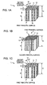
- Fig. 1A is a perspective view showing a first embodiment of a scintillator crystal body of the present invention.
- a first principal surface and a second principal surface have portions to which a second crystal phase is exposed, and a portion of the second crystal phase exposed to the first principal surface and a portion of the second crystal phase exposed to the second principal surface are connected to each other.
- a first crystal phase formed of many columnar crystals having a unidirectional characteristic is present in the second crystal phase.
- the phase separation structure includes two phases, that is, a first crystal phase 11 and a second crystal phase 12 that is filled between side surfaces of the columnar crystals of the first crystal phase 11.
- the phase separation structure is a structure containing a plurality of separated phases which is obtained when a uniform state is changed.
- the phase separation structure of this embodiment is a structure obtained in such a way that when a uniform liquid state having no concrete structure in which constituent materials are melted is changed to a solid state, two crystal phases are simultaneously crystallized to have a certain periodicity.
- a cross-sectional shape of a columnar crystal 18 forming the first crystal phase 11 may be formed of a plurality of crystal planes to have a polygonal shape.
- a diameter 13 of the columnar crystal 18 is in a range of 50 nm to 30 ⁇ m and preferably in a range of 200 nm to 10 ⁇ m.
- a period 14 of the columnar crystal 18 of the first crystal phase is in a range of 500 nm to 50 ⁇ m and preferably in a range of 1 to 20 ⁇ m.
- the columnar crystal when a scintillator crystal body and a photodetector or a photodetector array are used in combination, structural sizes thereof are preferably combined with each other so that many columnar crystals are arranged on a light receiving region of the photodetector.
- the shape of the light receiving region is a square having a 20- ⁇ m side
- the columnar crystal preferably has a structural size in which the diameter is 5 ⁇ m and the period is 8 ⁇ m.
- the range of the structural size is determined by the selection of material systems and the manufacturing conditions, and the tendency thereof will be described later.
- a thickness 15 of the scintillator crystal body can be adjusted to an arbitrary thickness. Since the scintillator crystal body detects radiation, the thickness of the crystal body must be sufficient to absorb its energy. For example, in the case of CsI which is a primary constituent material of the scintillator crystal body, a radiation length is 1.86 cm (distance at which the incident energy is reduced to 1/e) in a high energy region. Since it is calculated that 100% of energy is absorbed by 21 times the radiation length (39.06 cm), a sufficient thickness of the scintillator crystal body is 40 cm or less.
- the thickness 15 of the scintillator crystal body is in a range of 1 ⁇ m to 10 cm and preferably in a range of 10 ⁇ m to 10 mm.
- a scintillation crystal body having a thickness out of the range described above may also be used in some cases.
- the columnar crystals may be interrupted, branched, or fused and may include a curved portion besides the straight portion, and in addition, the diameter portion of the columnar crystal may be partially changed.
- the columnar crystal can be curved.
- the first crystal phase is preferably formed of a material containing NaBr (sodium bromide), NaCl (sodium chloride), NaF (sodium fluoride), or KCl (potassium chloride). In addition, NaCl is more preferable.
- the content of NaBr, NaCl, NaF, or KCl contained in the first crystal phase is 50 percent by mole or more and preferably in a range of 80 to 100 percent by mole.
- the second crystal phase preferably contains CsI (cesium iodide) as a primary component.
- the primary component of the second crystal phase indicates a material, the content of which is 50 percent by mole or more, and this primary component is preferably contained in an amount of 80 to 100 percent by mole in the second crystal phase.
- this primary component is CsI
- materials contained in the second crystal phase besides CsI, RbI (rubidium iodide), CsBr (cesium bromide), and RbBr (rubidium bromide) are preferable.
- the ratio of RbI to CsI is preferably in a range of more than 0 to 20 percent by mole. Even more preferably, the ratio is 15 percent by mole or less.
- the ratio of CsBr to CsI is preferably in a range of more than 0 to less than 50 percent by mole. More preferably, the ratio is 20 percent by mole or less.
- the ratio of RbBr to CsI is preferably in a range of more than 0 to 10 percent by mole.
- the transmittance of the crystal body along the columnar crystal is remarkably decreased. The reason for this is believed that a solid phase separation occurs, that is, an RbI or an RbBr component which cannot be solid-solved in CsI in the second crystal phase is precipitated.
- the importance of the scintillator crystal body of the present invention is the composition of materials for the first and the second crystal phases.
- the composition of materials forming the first and the second crystal phases contained in the scintillator crystal body of the present invention is preferably a composition at a eutectic point.
- the eutectic point is a point in an equilibrium diagram at which a eutectic reaction occurs and at which two types of solid solutions are simultaneously discharged from a liquid phase and solidification is completed.
- composition ratio of a preferable combination of the material system between the first and the second crystal phases of this embodiment is shown in the following Table 1.
- Table 1 FIRST CRYSTAL PHASE: SECOND CRYSTAL PHASE EUTECTIC COMPOSITION [mol%] EUTECTIC POINT [°C] NaBr : CsI 40:60 432 NaCl : CsI 30:70 490 NaF : CsI 5:95 599 KCl : CsI 40:60 447
- the acceptable range is limited to the vicinity of the composition as described above is that the phases have a eutectic relationship therebetween even in the structure formation and that in the vicinity of the eutectic composition, an excellent structure as shown in Fig. 1A can be obtained by unidirectional solidification.
- composition ranges that is, when the composition is deviated by more than 2 percent by mole, one phase precipitates first, and in view of the structure formation, the structure is disordered.
- the eutectic composition of Table 1 also includes a measurement error, although it is conceptionally important that the acceptable range of the eutectic composition be ⁇ 2 percent by mole, if an excellent structure is substantially obtained, a deviation of approximately ⁇ 4 percent by mole from the eutectic composition may also be accepted.
- the eutectic point shown in Table 1 indicates a temperature in the vicinity of the eutectic point and does not limit anything.
- the first and the second crystal phases may contain at least one component other than those mentioned above, and in particular, the component contained in the material forming the first crystal phase 11 is preferably a component which is solid-solved in the first crystal phase 11 and which is not solid-solved in the second crystal phase 12.
- the component contained in the material forming the second crystal phase 12 is preferably a component which is not solid-solved in the first crystal phase 11 and which is solid-solved in the second crystal phase 12.
- RbI may be added to CsI.
- the primary component of the second crystal phase 12 is CsI, and one of RbI, CsBr, and RbBr is added thereto to form the second crystal phase
- a composition having a eutectic relationship with the material composition forming the second crystal phase is preferably used.
- At least one material other than RbI, CsBr, and RbBr may be additionally added to the second crystal phase 12.
- at least one component which is solid-soluble in both phases may be added.
- the purpose of the addition of at least one material in an amount of 1 percent by mole or more other than the addition of an ultra small amount of a luminescence center which will be described later is to control the lattice constant and/or the band gap and further is to control a luminescent color and the like.
- the second crystal phase 12 containing a scintillator material as a primary component is excited by radiation irradiation and emits light.
- at least one of the first crystal phase and the second crystal phase may emit light by radiation excitation, and it is more preferable when the two crystal phases emit light.
- CsI when used as a primary component of the second crystal phase, it is preferable that NaBr, NaCl, NaF, and KCl, each of which forms the first crystal phase 11, also emit light although the radiation absorption ability thereof is inferior to that of CsI.
- a small amount of a component functioning as the luminescence center is preferably added to base materials forming the first crystal phase 11 and the second crystal phase 12.
- the second crystal phase which is at a high refractive-index side at least emits light by radiation, and the reason the low refractive-index side is allowed to emit light is based on a relatively high probability of generation of effects, such as scattering, and is not based on the light guide property.
- the case described above in which the two crystal phases emit light does not exclude the case in which the second crystal phase absorbs light emitted from the first crystal phase and the case opposite thereto.
- the case described above in which the two crystal phases emit light also does not exclude the case in which before emitting light, carriers generated in the first crystal phase enter the second crystal phase by diffusion and the case opposite thereto.
- the luminescence center a large number of luminescence centers may be selected in accordance with applications and the like, and a single element or a plurality of elements may be added.
- Na may also be selected.
- the luminescence center of the scintillator crystal body at least one of Tl, In, and Ga is more preferably contained.
- the element may be appropriately selected in consideration of desired luminance, luminescence wavelength, luminescent decay time, and the like.
- the luminescence center when added as described above, for example, the luminescence center is easily added to one of the two phases due to the phase separation structure, and concentration distribution may be generated in some cases; however, no problems may arise thereby.
- the luminescence by radiation described in the present invention also includes, besides general scintillation (luminescence by radiation irradiation), photostimulated phosphorescence (trap sites of carriers generated by radiation irradiation are excited by light irradiation, and light is emitted thereby).
- the light guide may be mentioned.
- the refractive indices of the material systems forming the first crystal phase 11 and the second crystal phase 12 are shown in Table 2.
- Table 2 MATERIAL SYSTEM REFRACTIVE INDEX OF FIRST CRYSTAL PHASE REFRACTIVE INDEX OF SECOND CRYSTAL PHASE REFRACTIVE INDEX RATIO OF FIRST CRYSTAL PHASE / SECOND CRYSTAL PHASE NaBr : CsI 1.64 1.80 0.911 NaCl : CsI 1.55 1.80 0.861 NaF : CsI 1.32 1.80 0.733 KCl : CsI 1.49 1.80 0.828
- the refractive index shown in Table 2 has wavelength dependence and is changed by an additive, the value thereof is not strict, and Table 2 is to show the difference in refractive index (shown by ratio in the table) between constituent materials.
- Snell's law between materials having different refractive indices, if light enters a low refractive-index medium at a certain angle from a high refractive-index medium, total reflection occurs, and at an angle smaller than that, reflection and refraction occur.
- the generation of difference in the refractive index shown in Table 2 indicates that light is not spread in the high refractive-index medium by total reflection under some conditions.
- the refractive-index ratio (low refractive-index crystal phase/high refractive-index crystal phase) is preferably at least less than 1.
- the refractive-index ratio is preferably at least less than 1.
- the combination of NaF with CsI is most preferable, and KCl, NaCl, and NaBr are preferable in this order.
- CsI functioning as a high refractive-index medium forms the second crystal phase 12. That is, since the second crystal phase forms a matrix around the columnar crystals in this embodiment, when the composition ratio (see Table 1) of the first crystal phase 11 forming the columnar crystals is low (for example, NaF: 5 percent by mole), light tends to pass between sides of the columnar crystals and to easily spread. In addition, when the composition ratio of the first crystal phase is high (for example, NaCl: 30 percent by mole), since the ratio of the second crystal phase formed of CsI having a high x-ray response is decreased, the luminous quantity is liable to relatively decrease.
- NaCl is more preferably used to form the first crystal phase 11 in view of the light guide.
- whether the combination is good or bad should be determined in accordance with each application; hence, whether the combination is good or bad is not simply determined by the refractive-index ratio and the composition ratio, and the above material systems are all important.
- the phase separation scintillator crystal body of the present invention is characterized in that light is guided in a direction parallel to the height direction of the columnar crystal (direction between the first principal surface and the second principal surface) and is not guided in a direction perpendicular thereto, for example, by scattering and reflection. Accordingly, the crosstalk of light can be suppressed without forming partitions in a single crystal group as in the related technique.
- NaI sodium iodide
- a phase separation structure of the columnar crystal structure shown in Fig. 1A or Fig. 1C or a lamella structure shown in Fig. 1B is obtained.
- these structures will be described in detail.
- Figs. 1A, 1B, and 1C are each a perspective view showing one mode of a scintillator crystal body of this embodiment.
- the structure shown in Fig. 1A is similar to that in the above first embodiment, and hence a description thereof will be partially omitted.
- the structure as shown in Fig. 1A in which two phases, that is, a first crystal phase 11 formed of many columnar crystals having a unidirectional characteristic and a second crystal phase 12 which is filled between side surfaces of the columnar crystals of the first crystal phase 11, are formed is hereinafter called a first configuration.
- a first crystal phase 11 and a second crystal phase 12 are each formed of plate crystals standing in one direction and are alternately disposed in close contact with each other is hereinafter called a second configuration.
- a third configuration the structure as shown in Fig. 1C in which two phases, that is, a second crystal phase 12 formed of many columnar crystals having a unidirectional characteristic and a first crystal phase 11 which is filled between side surfaces of the columnar crystals of the second crystal phase 12, are formed is hereinafter called a third configuration.
- a diameter 13 of the first crystal phase in the first configuration shown in Fig. 1A or a diameter 13 of the second crystal phase in the third configuration shown in Fig. 1C and a period 14 in Figs. 1A and 1C are preferably in the same ranges as those described in the first embodiment.
- the crystal phase includes the plate crystals, when the diameter and the period are defined by a shorter-side side, a diameter 13 and a structural period 14 of the plate crystals of the first crystal phase are preferably in ranges similar to those of the first configuration.
- the scintillator crystal body of this embodiment is used in combination with a photodetector or a photodetector array, as described in the first embodiment, structure sizes thereof are preferably combined with each other so that a plurality of columnar crystals or a plurality of plate crystals is arranged on a light receiving region of the photodetector.
- the shorter-side side thereof may have a size similar to that of the columnar crystal.
- the scintillator crystal body may have a preferable light guide property at least at the shorter-side side.
- a thickness 15 of the scintillator crystal body is similar to that of the first embodiment.
- the second crystal phase contains NaI as a primary component
- CsI, RbI, NaCl or NaF is more preferably contained as the first crystal phase.
- a material forming the first crystal phase is a material system which has a eutectic relationship with NaI
- the structure of this embodiment is preferably formed.
- One example of the available relationship between the material of the first crystal phase and that of the second crystal phase is as shown in Table 3. That is, in the case of the combination between NaI and CsI, the second configuration ( Fig. 1B ) is formed, the second crystal phase is NaI, and the first crystal phase is CsI.
- the third configuration Fig.
- the second crystal phase is NaI
- the first crystal phase is RbI
- the first configuration Fig. 1A
- the first crystal phase is NaCl
- the second crystal phase is NaI
- the second configuration Fig. 1B
- the second crystal phase is NaI
- the first crystal phase is NaF.
- the composition of the materials forming the first crystal phase and the second crystal phase is important in this embodiment.
- composition ratios are as shown in the following table 4, and the compositions are each preferably a composition at a eutectic point.
- Table 4 FIRST CRYSTAL PHASE: SECOND CRYSTAL PHASE EUTECTIC COMPOSITION [mol%] EUTECTIC POINT [°C] CsI : NaI 51:49 428 RbI : NaI 50:50 505 NaCl : NaI 40:60 573 NaF : NaI 18:80 596
- the acceptable range of the above composition is preferably ⁇ 4 percent by mole and is more preferably ⁇ 2 percent by mole.
- At least one material other than those described above may also be added to the first crystal phase and the second crystal phase.
- KI is added to NaI
- RbI is added to CsI
- CsI is added to RbI.
- the content of one of NaI, CsI, RbI, NaCl, and NaF, each of which is a material forming a corresponding crystal phase is set to 50 percent by mole or more and is preferably set in a range of 80 to 100 percent by mole.
- the second crystal phase of the phase separation structure since NaI which is a scintillator material is used for the second crystal phase of the phase separation structure in this embodiment, when NaI is excited by radiation irradiation, light can be emitted.
- at least one crystal phase preferably emits light in this embodiment, it is more preferable when the two crystal phases both emit light.
- a small amount of at least one element functioning as the luminescence center (hereinafter simply referred to as "luminescence center”) is preferably added to base materials forming the first crystal phase 11 and the second crystal phase 12.
- the luminescence center elements similar to those described in the first embodiment may also be used.
- the light guide may be mentioned.
- the refractive indices of the material systems forming the first crystal phase 11 and the second crystal phase 12 are shown in Table 5.
- Table 5 COMBINATION OF MATERIALS REFRACTIVE INDEX OF FIRST CRYSTAL PHASE REFRACTIVE INDEX OF SECOND CRYSTAL PHASE RATIO OF LOW REFRACTIVE INDEX / HIGH CsI-NaI 1.80 1.85 0.973 RbI-NaI 1.61 1.85 0.870 NaCl-NaI 1.55 1.85 0.838 NaF-NaI 1.32 1.85 0.714
- the volume of the low refractive-index material forming the first crystal phase when the volume of the low refractive-index material forming the first crystal phase is small, the visibility at the high refractive-index side becomes good, and light tends to easily pass through and spread in a lateral direction.
- the situation as described above may also occur in the NaCl-NaI (first configuration) and the CsI-NaI (second configuration) systems, it does not indicate that the light guide effect is not obtained therein, and although light is sufficiently guided as compared to the case of a NaI single crystal, the effect is not so good as that of the other material systems of this embodiment.
- the NaF-NaI system belongs to the second configuration, since the form of NaF is frequently branched into three ways, the visibility at the high refractive-index side is inferior to that of the CsI-NaI system, and light is unlikely to pass through in a lateral direction.
- the ability of light guide is not determined only by the ratio of the refractive index (difference in refractive index' between a low refractive-index material and a high refractive-index material).
- the radiation blocking capability in consideration of the composition ratio is high in the order of CsI-NaI, RbI-NaI, NaF-NaI, and NaCl-NaI.
- the radiation blocking capability since the radiation blocking capability has energy dependence, it may not be concluded in some cases that the radiation blocking capability is high in the order of CsI, RbI, NaI, NaCl, and NaF.
- NaI: Tl generally has a decay time (time to decay from the initial luminance to 1/e) of approximately 200 nsec (nano seconds) and is preferably used, for example, for a CT apparatus which obtains many images at a high speed.
- the luminescent decay time of CsI: Tl is approximately 500 ns which is approximately 2.5 times that of NaI: Tl.
- the luminescent decay time of the material system of the present invention is shown in Table 6.
- the number of each column in the table indicates the rank.
- the rank in the column of configuration indicates the light guide performance, that is, (1) the third configuration in which a high refractive-index material forms columnar crystals is ranked best; (2) the first configuration in which a low refractive-index material forms columnar crystals and (2) the specific second configuration (for example, being branched into three ways) are ranked at the same level; and (3) the second structure which is not specific is slightly inferior to the other configurations.
- the phase separation scintillator crystal body containing NaI of this embodiment has the properties in which light is guided along a direction parallel to the columnar crystals or the plate crystals and is not guided in a direction perpendicular thereto, for example, by scattering and reflection. Hence, the crosstalk of light can be suppressed without forming partitions in a single crystal group as in the related technique.
- the third embodiment is a mode in which a primary component of a second crystal phase is not limited to a scintillator material.
- a primary component of a second crystal phase is not limited to a scintillator material.
- NaBr or NaCl is used as a material which is not a scintillator material.
- a scintillator material may also be used, and in this case, RbI, CsBr, RbBr, CsCl, or RbCl is used in this embodiment.
- a phase separation structure of a columnar crystal structure shown in Fig. 1A or 1C or a lamellar crystal structure shown in Fig. 1B is obtained using one of the above materials as a primary component of the second crystal phase. This structure will be described in detail.
- a thickness 15 of a scintillator crystal body can be adjusted to a desired thickness.
- the thickness is large enough to absorb the energy thereof.
- RbI is 2.7 cm
- CsBr is 2.1 cm
- RbBr is 3.4 cm
- CsCl is 2.4 cm
- RbCl is 4.6 cm.
- the radiation length is an average distance necessary to decrease incident energy to 1/e.
- the thickness 15 is in a range of 1 ⁇ m to 15 cm and preferably in a range of 10 ⁇ m to 30 mm. Since being influenced by a set value of the absorption coefficient of radiation, the thickness is not limited to the range described above.
- This embodiment is realized when at least one phase uses as a primary component one of RbI, CsBr, RbBr, CsCl, and RbCl, each of which functions as a scintillator.
- RbI, CsBr, RbBr, CsCl, and RbCl each of which functions as a scintillator.
- one of NaF, NaCl and NaBr is used in combination with one of RbI, CsBr, and RbBr.
- a combination of NaCl with CsCl may be mentioned.
- a combination between RbCl and NaF or NaCl may also be mentioned.
- the second crystal phase which is a high refractive-index layer, may contain a material other than a scintillator material as a primary component in some cases.
- the second configuration ( Fig. 1B ) is formed, the second crystal phase, which is a high refractive-index phase, contains as a primary component NaBr which is not a scintillator material, and the first crystal phase contains as a primary component RbI which is a scintillator material.
- the composition of the material forming the first crystal phase and that forming the second crystal phase is important in the present invention.
- composition ratios are as shown in the following Table 9, and each combination is preferably composition at a eutectic point.
- the eutectic point is a point in an equilibrium diagram at which a eutectic reaction occurs and at which at least two types of crystals are simultaneously crystallized from a liquid phase and solidification is completed.
- the acceptable range of the above composition is preferably ⁇ 4 percent by mole and more preferably ⁇ 2 percent by mole.
- At least one material other than those mentioned above may also be added to the first crystal phase and the second crystal phase.
- NaBr may be added to NaCl
- CsI or RbBr may be added to RbI
- CsI, RbBr, or CsCl may be added CsBr
- RbI or CsBr may be added to RbBr.
- the ratio of CsI to RbI is in a range of more than 0 to 20 percent by mole
- the ratio of RbBr to RbI is in a range of more than 0 to less than 50 percent by mole.
- the ratio of CsI to CsBr is in a range of more than 0 to 50 percent by mole, and the ratio of RbBr to CsBr is in a range of more than 0 to 25 percent by mole, and the ratio of CsCl to CsBr is in a range of more than 0 to less than 50 percent by mole.
- the ratio of RbI to RbBr is in a range of more than 0 to 50 percent by mole, and the ratio of CsBr to RbBr is in a range of more than 0 to 15 percent by mole.
- RbI, CsBr, RbBr, CsCl, and RbCl are also used in the phase separation structure, when the above material is excited by radiation irradiation, light can be emitted.
- at least one of the crystal phases preferably emits light, it is more preferable that the two crystal phases emit light.
- a small amount of at least one element functioning as the luminescence center (hereinafter simply referred to as "luminescence center") is preferably added to base materials forming the first crystal phase 11 and the second crystal phase 12.
- the luminescence center elements similar to those described in the first embodiment may also be used.
- the light guide may be mentioned.
- the refractive indices of the material systems forming the first crystal phase 11 and the second crystal phase 12 are shown in Table 10.
- Table 10 COMBINATION OF MATERIALS REFRACTIVE INDEX OF FIRST CRYSTAL PHASE REFRACTIVE INDEX OF SECOND CRYSTAL PHASE RATIO OF LOW REFRACTIVE INDEX /HIGH REFRACTIVE INDEX NaF-RbI 1.32 1.61 0.82 NaCl-RbI 1.55 1.61 0.963 RbI-NaBr 1.61 1.64 0.982 NaF-CsBr 1.32 1.71 0.772 NaCl-CsBr 1.55 1.71 0.906 NaBr-CsBr 1.64 1.71 0.959 NaF-RbBr 1.32 1.53 0.863 RbBr-NaCl 1.53 1.55 0.987 RbBr-NaB
- the phase emitting light by radiation excitation is different from the phase responsible for light guide, the performance thereof is inferior to the other combinations; however, since effects, such as, scattering, may be generated at a relatively high probability, the above combination has an excellent light guide function compared to a single-phase scintillator crystal body.
- the third configuration that is, the RbBr-NaBr system
- the third configuration can be considered as a configuration in which light in not likely to spread in a lateral direction. That is, since the high refractive-index second crystal phase containing NaBr as a primary component forms the columnar crystals, in a portion of light generated in the first crystal phase containing RbBr as a primary component, light incident on the second crystal phase formed of the columnar crystals is, for example, scattered, so that the traveling path of the light is changed; hence, in some cases, the light thus scattered is guided by a light guide function and is suppressed from spreading.
- the capability to guide light is not determined only by the ratio of the refractive index (difference in refractive index between a low refractive-index material and a high refractive-index, material).
- the linear attenuation coefficient of each of RbI, CsBr, RbBr, CsCl, and RbCl is approximately equal to that of CsI.
- the linear attenuation coefficient of each of the above materials except CsCl is higher than that of CsI, in order to emit high luminescent light, the materials are preferably used in the energy range described above.
- the phase separation scintillator crystal body which contains RbI, CsBr, RbBr, CsCl, or RbCl as a primary component of this embodiment has features in which light is guided in a direction parallel to the columnar crystal or the plate crystal and is not guided in a direction perpendicular thereto, for example, by scattering and reflection. Accordingly, the crosstalk of light can be suppressed without forming partitions in a single crystal group as in the related technique.
- an alkaline earth halide is used as a primary component of a second crystal phase, and a phase separation structure of the lamella structure shown in Fig. 1B is obtained.
- This phase separation structure will be described in detail. Since the structure shown in Fig. 1B is already described in the above embodiments, the features of this embodiment will only be described in detail.
- a scintillator crystal body of this embodiment is a phase separation structure which includes a unidirectional first crystal phase and second crystal phase, and the second crystal phase is a formed of a material which contains as a primary component one of barium iodide (BaI 2 ), barium bromide (BaBr 2 ), barium chloride (BaCl 2 ), strontium bromide (SrBr 2 ), and strontium chloride (SrCl 2 ), each of which is alkaline earth halide.
- the feature of the scintillator crystal body is characterized in that at least one phase of the above structure emits light by radiation excitation.
- sodium iodide (NaI) is for barium iodide (BaI 2 )
- sodium bromide (NaBr) is for barium bromide (BaBr 2 )
- sodium chloride (NaCl) is for barium chloride (BaCl 2 ).
- sodium bromide (NaBr) is preferable for strontium bromide (SrBr 2 )
- sodium chloride (NaCl) is preferable for strontium chloride (SrCl 2 ).
- a phase separation structure is probably formed when a material system has a eutectic relationship with the above alkaline earth halide, other combinations are not excluded.
- At least one of the first crystal phase and the second crystal phase preferably contains at least one of europium (Eu), cerium (Ce), thallium (T1), indium (In), and gallium (Ga) as a luminescence center.
- the composition of the first crystal phase and the second crystal phase is preferably a composition at a eutectic point.
- Examples of available relationships between materials for the first crystal phase and materials for the second crystal phase are as shown in Table 11. [Table 11] COMBINATION OF MATERIALS CONFIGURATION FIRST CRYSTAL PHASE SECOND CRYSTAL PHASE NaI-BaI 2 SECOND CONFIGURATION NaI BaI 2 NaBr-BaBr 2 SECOND CONFIGURATION NaBr BaBr 2 NaCl-BaCl 2 SECOND CONFIGURATION NaCl BaCl 2 NaBr-SrBr 2 SECOND CONFIGURATION NaBr SrBr 2 NaCl-SrCl 2 SECOND CONFIGURATION NaCl SrCl 2 NaCl-SrCl 2 SECOND CONFIGURATION NaCl SrCl 2
- the composition of the material forming the first crystal phase and the material forming the second crystal phase is important in this embodiment.
- compositions are each preferably a composition at a eutectic point.
- FIRST CRYSTAL PHASE SECOND CRYSTAL PHASE EUTECTIC COMPOSITION
- Mol% EUTECTIC POINT [°C] NaI-BaI 2 50 : 50 491 NaBr-BaBr 2 60 : 40 600 NaCl-BaCl 2 60 : 40 651 NaBr-SrBr 2 40 : 60 457 NaCl-SrCl 2 48 : 52 565
- the acceptable range of the above composition is preferably ⁇ 4 percent by mole and more preferably ⁇ 2 percent by mole. Since an alkaline earth halide which is a scintillator material is used for the second crystal phase of the phase separation structure of this embodiment, when being excited by radiation irradiation, the second crystal phase can be made to emit light. Although at least one of the crystal phases preferably emits light in this embodiment, it is more preferable that the two crystal phases emit light. In particular, in order to increase the luminous efficiency, a small amount of an element functioning as the luminescence center is preferably added to base materials forming the first crystal phase 11 and the second crystal phase 12. As the luminescence center, at least one of europium (Eu), cerium (Ce), thallium (Tl), indium (In), and the gallium (Ga) is preferably contained.
- the optical guide may be mentioned.
- the refractive indices of the material systems each forming the first crystal phase 11 and the second crystal phase 12 are shown in Table 13. [Table 13] MATERIAL SYSTEM REFRACTIVE INDEX OF FIRST CRYSTAL PHASE REFRACTIVE INDEX OF SECOND CRYSTAL PHASE RATIO OF LOW REFRACTIVE INDEX / HIGH REFRACTIVE INDEX NaI-BaI 2 1.85 (2.0) 0.925 NaBr-BaBr 2 1.64 (1.8) 0.911 NaCl-BaCl 2 1.55 1.64 0.945 NaBr-SrBr 2 1.64 (1.75) 0.937 NaCl-SrCl 2 1.55 1.65 0.939
- the phase separation scintillator crystal body which contains an alkaline earth halide of this embodiment has features in which light is guided in a direction parallel to the plate crystal and is not guided in a direction parallel thereto, for example, by scattering and reflection. Accordingly, the crosstalk of light can be suppressed without forming partitions in a single crystal group as in the related technique.
- a method for manufacturing a scintillator crystal body according to this embodiment includes the steps of: mixing a material forming a first'crystal phase and a material forming a second crystal phase; then melting a mixture of the material forming a first crystal phase and the material forming a second crystal phase; and then solidifying the material forming a first crystal phase and the material forming a second crystal phase along one direction to form a eutectic compound.
- the method for manufacturing a scintillator crystal body of this embodiment can be realized by any method in which a desired material system having an optimal composition is melted and solidified to have a unidirectional characteristic.
- the control is preferably performed so that the temperature gradient at the solid-liquid interface of a mixture is 30°C/mm or more.
- the temperature gradient may be decreased as long as the structure formation of each of the above embodiments is not disturbed.
- reheating is preferably performed so as not to again melt a portion which is already formed into the crystal body.
- the formable composition range of the eutectic composition ⁇ 4 percent by mole and preferably ⁇ 2 percent by mole of the eutectic composition are described; however, the present inventors believe that the crystal body of the present invention should be formed within a range socalled "Coupled Eutectic Zone" in which an intrinsic relationship of material system holds among the acceptable range, the temperature gradient, and the solidification rate.
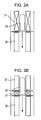
- Figs. 2A and 2B are each a schematic view showing a method for manufacturing a scintillator crystal body of this embodiment.
- a sample sealed for example, in a cylindrical quartz tube so as not to be oxidized is placed in a vertical direction, since a heater or the sample is moved at a predetermined rate, the solidification interface of the sample can be controlled; hence, the phase separation scintillator crystal body of this embodiment can be manufactured.
- an apparatus shown in Fig. 2A includes a heater portion 21 having a length equivalent to that of a sample 23 and a water-cooling portion 22 which realizes a temperature gradient of 30°C/mm or more at a solid-liquid interface of the sample 23 which is a mixture substance.
- a method performing steps equivalent to those described above may also be used.
- the temperature gradient may be less than 30°C/mm.
- a method for pulling up a crystal from a melt such as a Czochralski method, may also be used for the formation.
- a Czochralski method since solidification is not performed in a sample container of a Bridgman method, the solid-liquid interface can be formed without receiving any influences of the container wall surface, and hence the above method is more preferable.
- a floating zone method may also be used for the formation, since the material system of this embodiment has almost no infrared absorption properties, direct heating by infrared radiation cannot be performed as a heating method, and hence an addition material and the like must be devised.
- the solidification rate (pull-down rate of the sample by the apparatus) of the sample is preferably set to 850 mm/hour or less.
- the solidification rate is more preferably set to 500 mm/hour or less and is even more preferably set to 300 mm/hour or less.
- the convex surface is preferably controlled to a flat surface.
- a crystal formed with a convex-shaped solid-liquid interface may also be processed by cutting for the use.
- the diameter and the period of the columnar crystal of the phase separation scintillator crystal body depend on the solidification rate of the sample, and in particular, it is believed that as for the period of the columnar crystals, the following formula holds.
- the restriction of the manufacturing method there is a solidification rate which can control the solid-liquid interface to be flat and smooth, and hence, the period ⁇ is set in a range of 500 nm to 50 ⁇ m.
- the diameter of the columnar crystal is also set in a range of 50 nm to 30 ⁇ m.
- the cross-sectional shape of the columnar crystal may not be circular in some case, and when the above shape has an irregular form, the shortest diameter thereof is within the range described above.
- the ratio of the longest diameter to the shortest diameter is preferably 10 or less.
- the structure should be appropriately regarded as a lamella structure.
- some columnar crystals among a tremendous number of columnar crystals have a value of more than 10, when the average value is 10 or less, the columnar crystals are within the acceptable range.
- a lamellar structure can be more easily formed when the molar ratio of the material forming the first crystal phase and that forming the second crystal phase is closer to 1: 1, and hence, in consideration of this tendency, the formation conditions and the additives are preferably selected.
- composition ratio of the material forming the first crystal phase and that forming the second crystal phase of the phase separation scintillator crystal body described above is the value shown in each table, as for the starting composition, ⁇ 4 percent by mole or more may be deviated therefrom. That is, in a Bridgman method, when the entire sample is solidified in a unidirectional direction from the state in which the entire sample is melted, a material deviated from the eutectic composition is first precipitated at an initial solidification stage, and a remaining melt has the eutectic composition.
- the radiation detector of each of the above embodiments has the above scintillator crystal body and a photodetector, and the scintillator crystal body is disposed so that the first principal surface or the second principal surface faces the above photodetector.
- the scintillator crystal body is preferably disposed on the photodetector with or without at least one protective layer interposed therebetween.
- the phase separation scintillator crystal body of this embodiment can be used as a radiation detector for medical use, industrial use, high-energy physical use, and space use.
- the phase separation scintillator crystal body of this embodiment is preferably used when light must be guided in a specific direction toward a detector.
- the phase separation scintillator crystal body of this embodiment is effectively used in an x-ray CT apparatus in which partition formation is required and can replace a CsI needle crystal film of an x-ray flat panel detector (FPD).
- the phase separation scintillator crystal body of this embodiment preferably has a linear attenuation coefficient equivalent to that of CsI (cesium iodide).
- the luminescence wavelength of the scintillator may be adjusted by addition of another material or a luminescence center to base materials so as to fit with light-receiving sensitivity characteristics of a photodetector.
- the detector and the phase separation scintillator crystal body of this embodiment are preferably bonded or disposed to each other with or without at least one film or layer functioning as a protective layer, an antireflection layer, or the like.
- Examples 1 to 8 are examples corresponding to the first embodiment described above. The examples will be sequentially described from Example 1.
- Example 1 powders obtained by mixing NaBr, NaCl, NaF, and KCl (each material forming a first crystal phase) in an amount, respectively, of 40, 30, 5, and 40 percent by mole with CsI (material forming a second crystal phase composition) were prepared, and the powders were separately vacuum-sealed in respective quartz tubes, thereby forming samples. Next, after each of those samples was introduced into a Bridgman furnace as shown in Fig.
- the difference in temperature at a solid-liquid interface which was the boundary between a portion at which the sample was melted and a portion at which the sample was solidified was set to 30°C/mm or more. As described above, the sample was solidified along one direction, so that a eutectic compound was generated.
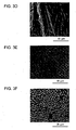
- the structure (structure viewed from the first principal surface, the second principal surface) of a plane perpendicular to the solidification direction was as shown in Fig. 3C and the structure in a parallel direction was as shown in Fig. 3D .
- the columnar crystal contained NaF and the periphery thereof contained CsI.
- phase separation scintillator structure of the present invention in which the second crystal phase included CsI was confirmed.
- samples were formed by adding 0.01 percent by mole of InI (indium iodide (I)), 0.01 percent by mole of TlI (thallium iodide (I)), and 0.01 percent by mole of Ga (added in a metal state) to the CsI-NaCl system.
- InI indium iodide
- TlI thallium iodide
- Ga added in a metal state
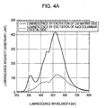
- Fig. 4 Two spectra of Fig. 4A are each the average of spectra obtained by electron beam excitation of six points in each of two scanning electron microscope images shown in Fig. 4B . In addition, three points out of the six excited points are illustrated in each image shown in Fig. 4B .
- a solid line spectrum indicates the luminescence in the region containing CsI, and green luminescence was observed.
- a dotted line spectrum was obtained when the columnar crystal containing NaCl was excited, and it was confirmed that a luminescence peak position was almost the same as that of the solid line spectrum and that the luminescence was green.
- phase separation scintillator crystal body of the present invention emitted light regardless of whether the luminescence center was added or not and at the same, as one example, the first and the second crystal phases both emitted light in the case of the In center.
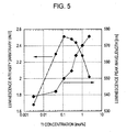
- This example relates to the luminous quantity with respect to a Tl concentration in the system in which TlI was added to CsI-NaCl which was a phase separation scintillator crystal body.
- Fig. 5 the luminescence wavelength and the relative luminance with respect to the TlI concentration added to CsI-NaCl are shown.
- the optimum value of the Tl concentration with respect to the luminous quantity was in a range of 0.04 to 1.0 percent by mole.
- the optimal concentration may not be limited only to the above range in consideration of a sensitivity curve of a light receiving element, and the optimal range may be determined in consideration of the above two factors.
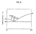
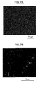
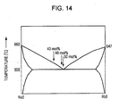
- composition of the phase separation scintillator crystal body of the present invention three samples shown by arrows in a phase diagram shown in Fig. 6 , that is, CsI-NaCl (20 percent by mole), CsI-NaCl (28 percent by mole), and CsI-NaCl (30 percent by mole), were formed by an apparatus similar to that of Example 1 shown in Fig. 2A and were formed by an apparatus as shown in Fig. 2B in which a heater portion was narrow, and a sample was locally melted, thereby forming totally 6 types of samples.
- Example 1 In the case similar to that Example 1 in which solidification was started after the entire sample was melted at an early stage, it was found that by all the samples formed as described above, as the structure of the first principal surface and that of the second principal surface, an excellent structure as shown in a scanning electron microscope (SEM) image of Fig. 7A was obtained. However, in the case of NaCl (20 percent by mole), a crystal was formed together with precipitation of CsI dendrites in a solidification initial area of the sample as shown in Fig. 7B , and thereafter, an excellent region as shown in Fig. 7A was formed.
- SEM scanning electron microscope
- phase separation scintillator crystal body of the present invention although a slight fluctuation of the composition of approximately 2 percent by mole had not considerable adverse influence on the structure formation, a considerable fluctuation of 10 percent by mole had adverse influences; hence, it was clear that the optimal composition was in the vicinity of the eutectic composition.
- the optimal composition was in the vicinity of the eutectic composition.
- the controllability of the structure size will be described using a CsI-NaCl system as an example.
- Four powders in which 30 percent by mole of NaCl was mixed with CsI were prepared in quartz seal tubes, and the samples were formed by a manufacturing method similar to that of Example 1.
- the pull-down rates of the samples were 10.4, 31.3, 94.0, and 232 mm/hour.
- the formed sample was cut along a plane perpendicular to the solidification direction, and the surfaces of the sample (the first principal surface, the second principal surface) were observed by a SEM, and the diameter and the period of the NaCl columnar crystal of the phase separation structure were obtained.
- a structural period of 50 ⁇ m is obtained at a pull-down rate of 0.055 mm/hour (1.319 mm/day)) close to 1 mm/day which is a rough indication of a very low rate.
- a structural period of 500 nm is obtained at a pull-down rate of 813 mm/hour close to 850 mm/hour which is a rough indication of an upper limit of a fast rate.
- a diameter of approximately 20.4 ⁇ m is obtained at a rate of 0.055 mm/hour, and a diameter of approximately 209 nm is obtained at a rate of 813 mm/hour.
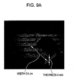
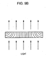
- Fig. 9A shows the case in which a phase separation scintillator crystal body of In-doped CsI-NaCl (30 percent by mole) formed by a Bridgman method was disposed on the plane.
- the thickness of the crystal was approximately 4 mm.
- characters printed on the plane were observed as if floating through the crystal body, and this indicated that no light scattering factors were present in a direction perpendicular to the plane on which the characters were printed.
- phase separation scintillator crystal body of the present invention had properties of reliably guiding light only in the columnar crystal direction.
- This example relates to the case in which the second crystal phase contains CsI as a primary component, and one of RbI, CsBr, and RbBr is added thereto.
- samples in which the compositions of RbI with respect to CsI were 15, 30, and 50 percent by mole, samples in which the compositions of CsBr were 20 and 50 percent by mole, and samples in which the compositions of RbBr were 10, 15, and 50 percent by mole were formed by a manufacturing method similar to that of Example 1.
- the light guide characteristics are shown by the following 4 classes, that is, ⁇ : excellent light guide, ⁇ : slight degradation in light guide; ⁇ : light guide property is inferior but light guide is performed along the structure; x: no light guide by the structure.
- ⁇ excellent light guide
- ⁇ slight degradation in light guide
- ⁇ light guide property is inferior but light guide is performed along the structure
- x no light guide by the structure.
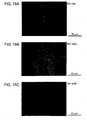
- Figs. 10A to 10C transmission microscope photographs of the first or the second principal surface of the sample having an excellent light guide property are shown.
- Fig. 10A shows a sample in which 15 percent by mole of RbI was added
- Fig. 10B shows a sample in which 20 percent by mole of CsBr was added
- Fig. 10C shows a sample in which 10 percent by mole of RbBr was added.
- scratches and/or defects shown in the figures were generated when the sample was processed by cutting, the essence of the present invention was not influenced thereby.
- phase separation scintillator crystal body of the present invention could be formed.
- This example relates to radiation detection using the phase separation scintillator described in one of the above examples.
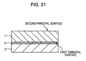
- a phase separation scintillator crystal body cut into a thickness of 1 mm was arranged on a photodetector array so that the first principal surface or the second principal surface faced photodetectors, and as a result, a radiation detector shown in Fig. 21 was formed.
- Reference numeral 1 in the figure indicates the phase separation scintillator crystal body described in one of the above examples
- reference numeral 2 indicates the photodetector
- reference numeral 3 indicates a substrate.
- a Tl-added CsI needle crystal film having a thickness of 430 ⁇ m was prepared by a common deposition method as a comparative example, and the spread of light was compared with a Tl-added CsI-NaCl system having a thickness of 1.42 mm as the phase separation scintillator crystal body of the present invention.
- the sample was irradiated with x rays obtained at 60 kV and 1 mA without an Al filter using a tungsten bulb through an opening having a diameter of 100 ⁇ m provided in a tungsten sheet having a thickness of 2 mm, and the light intensity distribution at the bottom surface of the sample was measured. Measurement was performed using CCDs at a 50-micrometer pitch.
- the intensity profile of the cross-section which passes through the peak value of the distribution is shown in Fig. 11 .
- each profile is normalized by the peak value and the relative position is determined with respect to the peak position.
- the full width at half maximum (FWHM) of the CsI needle crystal film was approximately 340 ⁇ m
- the FWHM of the CsI-NaCl crystal body of the present invention was approximately 160 ⁇ m, and it was found that the spread of light was suppressed to not more than one half.
- the crystal body of the present invention had a thickness of no less than 1.42 mm, it was confirmed that the spread of light was suppressed as compared to the CsI needle crystal film having a thickness of 430 ⁇ m which had been thought to have a light guide effect, and that the crystal body of the present invention had advantages as a scintillator having a light guide function.
- Examples 9 to 11 are examples corresponding to the above second embodiment.
- NaI was used as a primary component of the second crystal phase.
- powders formed by mixing each of CsI, RbI, NaCl, and NaF with NaI to have a concentration of 51, 50, 40, and 18 percent by mole were prepared, and the powders were separately vacuum-sealed in respective quartz tubes, thereby forming samples.
- the sample was placed in a Bridgman furnace as shown by the perspective view of Fig. 2A and was increased in temperature to 800°C so as to be entirely melted, the temperature was held for 30 minutes, and the melt temperature was then decreased to a temperature 20°C higher than the eutectic point shown in Table 4.
- the sample was pulled down at a rate of approximately 10 mm/hour so that the sample was sequentially solidified from a lower portion thereof.
- the difference in temperature at a solid-liquid interface which was the boundary between a portion at which the sample was melted and a portion at which the sample was solidified was set to 30°C/mm or more.
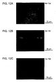
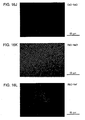
- the four types of samples thus formed were processed by cutting, and the transmission image of the first principal surface or the second principal surface was obtained by an optical microscope. The results are shown in Figs. 12A to 12E .
- Fig. 12A shows a plane (the first principal surface, the second principal surface) perpendicular to the solidification direction of a NaI-CsI system. From Fig. 12A , the structure in which plate crystals were alternately disposed in close contact with each other, that is, the second configuration, was confirmed.
- Fig. 12B shows a plane (the first principal surface, the second principal surface) perpendicular to the solidification direction of a NaI-RbI system. From Fig. 12B , the structure in which many NaI columnar crystals were surrounded by RbI, that is, the third configuration, was confirmed.
- Fig. 12C shows a plane parallel to the solidification direction of a NaI-RbI system. From Fig. 12C , it was confirmed that long NaI columnar crystals were grown along the solidification direction. That is, this indicated that a unidirectional phase separation structure was formed.
- Fig. 12D shows a plane (the first principal surface, the second principal surface) perpendicular to the solidification direction of a NaI-NaCl system.
- Fig. 12E shows a plane (the first principal surface, the second principal surface) perpendicular to the solidification direction of a NaI-NaF system. From Fig. 12E , it was found that the NaF plate crystal had a three-branch structure.
- the optical microscope images shown in Figs. 12A to 12E were obtained by a transmission arrangement, and the NaI plate crystal side of the NaI-CsI system, the NaI columnar crystal side of the NaI-RbI system, the NaI matrix side of the NaI-NaCl system, and the NaI matrix side of the NaI-NaF system were more brightly observed. These results also indicated that the systems described above had a light guide function.
- the structure of the present invention in which one of the two phases was formed from NaI functioned as a phase separation scintillator and also had a light guide property.
- This example relates to the addition of a luminescence center.
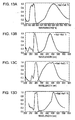
- the horizontal axis indicates the wavelength, the spectrum at a short wavelength side is an excitation spectrum, and the spectrum at a long wavelength side is an emission spectrum.
- the excitation spectrum was measured at the peak position of the emission spectrum.
- the NaI-CsI system, the NaI-RbI system, the NaCl-NaI system, and the NaI-NaF system correspond to Figs. 13A, 13B, 13C, and 13D , respectively. From these spectra, it was confirmed that the samples were all based on blue high luminescence of NaI: Tl known as a material system having high luminance.
- the phase separation scintillator crystal body of the present invention emits light by radiation excitation.
- This example relates to the composition of a phase separation scintillator.
- phase separation scintillator crystal body of the present invention although a slight fluctuation of the composition of approximately 2 percent by mole had not considerable adverse influence on the structure formation, a considerable fluctuation of 10 percent by mole had adverse influences; hence, it was clear that the optimal composition was in the vicinity of the eutectic composition.
- the optimal composition was in the vicinity of the eutectic composition.
- Examples 12 to 15 are examples corresponding to the above third embodiment and will be sequentially described.
- Example 12 powders each having a eutectic composition of the same material system as that shown in Table 9 were prepared and were vacuum-sealed in respective quartz tubes to form samples.
- the sample was placed in a Bridgman furnace as shown by the perspective view of Fig. 2A and was increased in temperature to 800°C so as to be entirely melted, the temperature was held for 30 minutes, and the melt temperature was then decreased to a temperature 20°C higher than the eutectic point shown in Table 9. Subsequently, the sample was pulled down at a rate of approximately 10 mm/hour so as to be sequentially solidified from a lower portion thereof.
- the difference in temperature at a solid-liquid interface which was the boundary between a portion at which the sample was melted and a portion at which the sample was solidified was set to 30°C/mm or more.
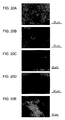
- the samples thus formed were each processed by cutting along a plane (the first principal surface or the second principal surface) perpendicular to the pull-down direction of the sample, and the transmission image was obtained by an optical microscope. The results are shown in Figs. 15A to 15F .
- Fig. 15A shows an image of the RbI-NaF system. From Fig. 15A , it was found that the structure was formed such that columnar crystals of NaF were surrounded by RbI. This structure corresponded to the first configuration, the first crystal phase was NaF, and the second crystal phase was RbI.
- Fig. 15B shows an image of the RbI-NaCl system. From Fig. 15B , it was found that the structure was formed such that columnar crystals of NaCl were surrounded by RbI. This structure corresponded to the first configuration, the first crystal phase was NaCl, and the second crystal phase was RbI.
- Fig. 15C shows an image of the RbI-NaBr system. From Fig. 15C , it was found that the structure was formed such that plate crystals of NaBr and plate crystals of RbI were alternately disposed in close contact with each other. This structure corresponded to the second configuration, the first crystal phase was RbI and the second crystal phase was NaBr.
- Fig. 15D shows an image of the CsBr-NaF system. From Fig. 15D , it was found that the structure was formed such that columnar crystals of NaF were surrounded by CsBr. This structure corresponded to the first configuration, the first crystal phase was NaF, and the second crystal phase was CsBr.
- Fig. 15E shows an image of the CsBr-NaCl system. From Fig. 15 (E) , it was found that the structure was formed such that columnar crystals of NaCl were surrounded by CsBr. This structure corresponded to the first configuration, the first crystal phase was NaCl, and the second crystal phase was CsBr.
- Fig. 15F shows an image of the CsBr-NaBr system. From Fig. 15F , it was found that the structure was formed such that columnar crystals of NaBr were surrounded by CsBr. This structure corresponded to the first configuration, the first crystal phase was NaBr, and the second crystal phase was CsBr.
- Fig. 16G shows an image of the RbBr-NaF system. From Fig. 16G , it was found that the structure was formed such that columnar crystals of NaF were surrounded by RbBr. This structure corresponded to the first configuration, the first crystal phase was NaF, and the second crystal phase was RbBr.
- Fig. 16H shows an image of the RbBr-NaCl system. From Fig. 16H , it was found that the structure was formed such that plate crystals of NaCl and plate crystals of RbBr were alternately disposed in close contact with each other. This structure corresponded to the second configuration, the first crystal phase was RbBr, and the second crystal phase was NaCl.
- Fig. 16I shows an image of the RbBr-NaBr system. From Fig. 16I , it was found that the structure was formed such that columnar crystals of NaBr were surrounded by RbBr. This structure corresponded to the third configuration, the first crystal phase was RbBr, and the second crystal phase was NaBr.
- Fig. 16J shows an image of the CsCl-NaCl system. From Fig. 16J , it was found that the structure was formed such that columnar crystals of NaCl were surrounded by CsCl. This structure corresponded to the first configuration, the first crystal phase was NaCl, and the second crystal phase was CsCl.
- Fig. 16K shows an image of the RbCl-NaCl system. From Fig. 16K , it was found that the structure was formed such that columnar crystals of NaCl were surrounded by RbCl. This structure corresponded to the third configuration, the first crystal phase was RbCl, and the second crystal phase was NaCl.
- Fig. 16L shows an image of the RbCl-NaF system. From Fig. 16L , it was found that the structure was formed such that columnar crystals of NaF were surrounded by RbCl. This structure corresponded to the first configuration, the first crystal phase was NaF, and the second crystal phase was RbCl.
- the optical microscope images shown in Figs. 15A to 16L were each obtained by a transmission arrangement, and it was confirmed that the crystal phase which looked bright in each image was formed of the material at a higher refractive index side (second crystal phase) shown in Table 10; hence, it was shown that the scintillator crystal body of the present invention had a light guide function by the difference in refractive index.
- a phase separation scintillator structure in which one of the two phases contained RbI, CsBr, RbBr, CsCl, or RbCl as a primary component also had a light guide property.
- This example relates to a concrete example in which another material was added to RbI, CsBr, or RbBr which formed one of the crystal phases.
- Example 12 As in the case of Example 12, the following material systems were vacuum-sealed in respective quartz tubes, and samples were formed.
- CsBr80-CsI20 NaCl
- CsBr50-CsI50 NaCl
- CsBr80-RbBr20 NaCl
- CsBr80-CsCl20 NaCl
- CsBr60-CsCl40 CsBr60-CsCl40
- RbBr95-RbI5)-NaCl RbBr50-RbI50-NaCl
- RbBr90-CsBr10-NaCl RbBr10-NaCl
- the sample thus formed was processed by cutting along a plane (the first principal surface, the second principal surface) perpendicular to the pull-down direction as in the case of Example 12, and the transmission image was obtained by an optical microscope. The results are shown in Figs. 17A to 17F .
- Fig. 17A shows an image of the (RbI85-CsI15)-NaCl system. From Fig. 17A , it was found that the structure was formed such that NaCl columnar crystals were surrounded by a (RbI85-CsI15) mixed crystal. This structure corresponded to the first configuration, the first crystal phase was NaCl, and the second crystal phase was (RbI85-CsI15).
- Fig. 17B shows an image of the (RbI80-RbBr20)-NaCl system. From Fig. 17B , it was found that the structure was formed such that NaCl columnar crystals were surrounded by a (RbI80-RbBr20) mixed crystal. This structure corresponded to the first configuration, the first crystal phase was NaCl, and the second crystal phase was (RbI80-RbBr20).
- Fig. 17C shows an image of the (CsBr80-CsI20)-NaCl system. From Fig. 17C , it was found that the structure was formed such that NaCl columnar crystals were surrounded by a (CsBr80-CsI20) mixed crystal. This structure corresponded to the first configuration, the first crystal phase was NaCl, and the second crystal phase was (CsBr80-CsI20).
- Fig. 17D shows an image of the (CsBr50-CsI50)-NaCl system. From Fig. 17D , it was found that the structure was formed such that NaCl columnar crystals were surrounded by a (CsBr50-CsI50) mixed crystal. This structure corresponded to the first configuration, the first crystal phase was NaCl, and the second crystal phase was (CsBr50-CsI50).
- Fig. 17F shows an image of the (CsBr80-CsCl20)-NaCl system. From Fig. 17F , it was found that the structure was formed such that NaCl columnar crystals were surrounded by a (CsBr80-CsCl2 mixed crystal. This structure corresponded to the first configuration, the first crystal phase was NaCl, and the second crystal phase was (CsBr80-CsCl20).
- Fig. 18G shows an image of the (CsBr60-CsCl40)-NaCl system. From Fig. 18G , it was found that the structure was formed such that NaCl columnar crystals were surrounded by a (CsBr60-CsCl40) mixed crystal. This structure corresponded to the first configuration, the first crystal phase was NaCl, and the second crystal phase was (CsBr60-CsCl40).
- Fig. 18H shows an image of the (RbBr95-RbI5)-NaCl system. From Fig. 18H , it was found that the structure was formed such that NaCl plate crystals and plate crystals of a (RbBr95-RbI5) mixed crystal were alternately disposed in close contact with each other. This structure corresponded to the second configuration, the first crystal phase was (RbBr95-RbI5), and the second crystal phase was NaCl.
- Fig. 18I shows an image of the (RbBr50-RbI50)-NaCl system. From Fig. 18I , it was found that the structure was formed such that NaCl columnar crystals were surrounded by a (RbBr50-RbI50) mixed crystal. This structure corresponded to the first configuration, the first crystal phase was NaCl, and the second crystal phase was (RbBr50-RbI50).
- Fig. 18J shows an image of the (RbBr90-CsBr10)-NaCl system. From Fig. 18J , it was found that the structure was formed such that NaCl plate crystals and plate crystals of a (RbBr90-CsBr10) mixed crystal were alternately disposed in close contact with each other. This structure corresponded to the second configuration, the first crystal phase was (RbBr90-CsBr10), and the second crystal phase was NaCl.
- the optical microscope images shown in Figs. 17A to 18J were each obtained by a transmission arrangement, and it was confirmed that the crystal phase which looked bright in each image was formed of the material at a higher refractive index side (second crystal phase); hence, it was shown that the scintillator crystal body of the present invention had a light guide function by the difference in refractive index.
- this structure functioned as a phase separation scintillator and also had a light guide property.
- This example relates to the addition of a luminescence center.
- samples were formed by combinations in which 0.01 percent by mole of TlI (thallium iodide), InI (indium iodide), and Ga (gallium) were separately added to all material systems.
- TlI thallium iodide
- InI indium iodide
- Ga gallium
- phase separation structure of the present invention functioned as a scintillator crystal body which could emit light by radiation excitation.
- This example relates to the composition of a phase separation scintillator.
- CsBr-NaCl 38 percent by mole
- CsBr-NaCl 40 percent by mole
- the molar ratios of CsBr to NaCl are 62: 38 and 60: 40, respectively.
- phase separation scintillator crystal of the present invention although a slight fluctuation of the composition, such as approximately 2 percent by mole, had not considerable adverse influence on the structure formation, since a considerable fluctuation of 10 percent by mole had influences, it was clear that the optimal composition was in the vicinity of the eutectic composition. In addition, it was found that when solidification was controlled after the entire sample was melted in the manufacturing, even if the composition was deviated from the eutectic composition, a deviated material was preferentially precipitated in the solidification initial area of the sample, and an excellent region could be obtained from the remaining melt of the eutectic composition, and this finding is important.
- Examples 16 and 17 are examples corresponding to the above fourth embodiment and will be described in this order.
- the difference in temperature at a solid-liquid interface which was the boundary between a portion at which the sample was melted and a portion at which the sample was solidified was set to 30°C/mm or more.
- Five types of samples thus formed were each processed by cutting, and the transmission image (image of the first principal surface, the second principal surface) was obtained by an optical microscope. As a result, images of Figs. 20A to 20E of the five material systems were obtained.
- This example relates to the addition of a luminescence center.
- samples were formed in which five material systems, that is, BaI 2 -NaI, BaBr 2 -NaBr, BaCl 2 -NaCl, SrBr 2 -NaBr, and SrCl 2 -NaCl, were each added with 0.5 percent by mole of one selected from EuI 2 , EuBr 2 , and EuCl 2 so that the halogens coincided therebetween.
- five material systems that is, BaI 2 -NaI, BaBr 2 -NaBr, BaCl 2 -NaCl, SrBr 2 -NaBr, and SrCl 2 -NaCl
- Example 8 when the radiation detector shown in Fig. 21 was formed such that the phase separation scintillator crystal body described in one of Examples 9 to 17 described above was disposed on a photodetector array so that the first principal surface or the second principal surface faces photodetectors, it was also confirmed from an output of the photodetector array that compared to a radiation detector using a single crystal scintillator without using partitions, the spread of light was suppressed.
- phase separation scintillator crystal body of the present invention Since emitting light by radiation and having properties of guiding emitted light, when the phase separation scintillator crystal body of the present invention is used in combination with a photodetector without forming related partitions, this combination is quite useful as a radiation detector.
- the phase separation scintillator crystal body of this embodiment can be used, for example, as a measurement apparatus for medical use, industrial use, high-energy physical use, and space use, in each of which radiation, such as x rays, is used.
Landscapes
- Chemical & Material Sciences (AREA)
- Engineering & Computer Science (AREA)
- Materials Engineering (AREA)
- Organic Chemistry (AREA)
- Inorganic Chemistry (AREA)
- Crystallography & Structural Chemistry (AREA)
- Health & Medical Sciences (AREA)
- Life Sciences & Earth Sciences (AREA)
- General Physics & Mathematics (AREA)
- High Energy & Nuclear Physics (AREA)
- Molecular Biology (AREA)
- Spectroscopy & Molecular Physics (AREA)
- Physics & Mathematics (AREA)
- Metallurgy (AREA)
- Measurement Of Radiation (AREA)
- Luminescent Compositions (AREA)
- Apparatus For Radiation Diagnosis (AREA)
Applications Claiming Priority (5)
| Application Number | Priority Date | Filing Date | Title |
|---|---|---|---|
| JP2010017378 | 2010-01-28 | ||
| JP2010088982 | 2010-04-07 | ||
| JP2010162017 | 2010-07-16 | ||
| JP2010269728 | 2010-12-02 | ||
| PCT/JP2011/050798 WO2011093176A2 (en) | 2010-01-28 | 2011-01-12 | Scintillator crystal body, method for manufacturing the same, and radiation detector |
Publications (2)
| Publication Number | Publication Date |
|---|---|
| EP2517049A2 EP2517049A2 (en) | 2012-10-31 |
| EP2517049B1 true EP2517049B1 (en) | 2014-01-08 |
Family
ID=44319931
Family Applications (1)
| Application Number | Title | Priority Date | Filing Date |
|---|---|---|---|
| EP11703937.0A Not-in-force EP2517049B1 (en) | 2010-01-28 | 2011-01-12 | Scintillator crystal body, method for manufacturing the same, and radiation detector |
Country Status (5)
| Country | Link |
|---|---|
| US (2) | US8674309B2 (enExample) |
| EP (1) | EP2517049B1 (enExample) |
| JP (1) | JP5143243B2 (enExample) |
| CN (1) | CN102725658B (enExample) |
| WO (1) | WO2011093176A2 (enExample) |
Families Citing this family (25)
| Publication number | Priority date | Publication date | Assignee | Title |
|---|---|---|---|---|
| JP5138104B2 (ja) * | 2011-03-30 | 2013-02-06 | キヤノン株式会社 | 多孔質シンチレータ結晶体 |
| JP2013024731A (ja) * | 2011-07-21 | 2013-02-04 | Canon Inc | 放射線検出装置 |
| JP5947499B2 (ja) * | 2011-07-26 | 2016-07-06 | キヤノン株式会社 | 放射線検出器 |
| WO2013027671A1 (ja) * | 2011-08-19 | 2013-02-28 | 国立大学法人東北大学 | シンチレーター |
| CN103917895B (zh) * | 2012-05-16 | 2016-06-15 | 吉林省锐意美科技有限公司 | 像素化闪烁晶体薄膜及其制备和应用 |
| JP6192314B2 (ja) * | 2013-03-05 | 2017-09-06 | キヤノン株式会社 | シンチレータ結晶体および放射線検出器 |
| JP6289157B2 (ja) * | 2013-03-05 | 2018-03-07 | キヤノン株式会社 | シンチレータ及び放射線検出器 |
| WO2014180658A1 (en) | 2013-05-08 | 2014-11-13 | Koninklijke Philips N.V. | Gamma radiation detection device |
| WO2015008542A1 (ja) | 2013-07-16 | 2015-01-22 | 株式会社 東芝 | 放射線検出器、シンチレータパネルおよびそれらの製造方法 |
| JP6271909B2 (ja) * | 2013-08-20 | 2018-01-31 | キヤノン株式会社 | シンチレータ結晶体及び放射線検出器 |
| JP6304991B2 (ja) * | 2013-09-27 | 2018-04-04 | キヤノン株式会社 | シンチレータ結晶体及び放射線検出器 |
| WO2015072197A1 (ja) * | 2013-11-15 | 2015-05-21 | 株式会社 東芝 | 放射線検出器、シンチレータパネルおよびそれらの製造方法 |
| US20170355905A1 (en) * | 2014-11-19 | 2017-12-14 | The Regents Of The University Of California | Novel thallium doped sodium, cesium or lithium iodide scintillators |
| JP6402635B2 (ja) * | 2015-01-19 | 2018-10-10 | コニカミノルタ株式会社 | シンチレータ、シンチレータパネルおよびシンチレータパネルの製造方法 |
| EP3865917A1 (en) | 2015-02-16 | 2021-08-18 | Saint-Gobain Ceramics and Plastics, Inc. | Scintillation crystal including a co-doped sodium halide, and a radiation detection apparatus including the scintillation crystal |
| KR102547798B1 (ko) * | 2015-12-08 | 2023-06-26 | 삼성전자주식회사 | 방사선 검출기 및 이를 채용한 방사선 촬영 장치 |
| JP2017149883A (ja) * | 2016-02-26 | 2017-08-31 | 国立大学法人東北大学 | シンチレータおよび放射線検出器 |
| JP6763205B2 (ja) * | 2016-06-16 | 2020-09-30 | コニカミノルタ株式会社 | 積層型シンチレータパネル |
| KR20180033352A (ko) * | 2016-09-23 | 2018-04-03 | 삼성디스플레이 주식회사 | 캡핑층을 포함하는 유기발광 표시장치 |
| CN112166349B (zh) * | 2018-05-25 | 2024-09-03 | 卢克西姆解决方案有限责任公司 | 包含反离子和其他多价阳离子以减少余辉的CsI(Tl)闪烁体晶体,以及包括所述闪烁晶体的放射线检测装置 |
| CN109782328B (zh) * | 2019-01-11 | 2021-03-26 | 惠科股份有限公司 | 射线转换器和射线探测平板装置 |
| CN111528888B (zh) * | 2020-04-30 | 2022-02-11 | 南昌大学 | 一种基于自锁结构发光晶体的单光子发射断层成像结构 |
| JP2022035733A (ja) * | 2020-08-21 | 2022-03-04 | 国立大学法人東北大学 | シンチレータ |
| US12449555B2 (en) | 2022-03-08 | 2025-10-21 | Luxium Solutions, Llc | CsI(T1) scintillator crystal including co-dopants antiomy and bismuth to reduce afterglow, and a radiation detection apparatus including the scintillation crystal |
| FR3142485B1 (fr) * | 2022-11-29 | 2025-11-28 | Saint Gobain Cristaux Et Detecteurs | Materiau scintillateur, procede de fabrication et application de ce materiau |
Family Cites Families (24)
| Publication number | Priority date | Publication date | Assignee | Title |
|---|---|---|---|---|
| JPS5435060A (en) | 1977-08-20 | 1979-03-14 | Satake Eng Co Ltd | Grain milling device |
| JPS5979448A (ja) | 1982-10-29 | 1984-05-08 | Nakamichi Corp | 音響機器の動作禁止装置 |
| JP3297078B2 (ja) * | 1991-05-24 | 2002-07-02 | 株式会社東芝 | X線イメージ管およびその製造方法 |
| UA27013C2 (uk) | 1996-05-14 | 2000-02-28 | Спільне Українсько-Американське Підприємство "Амкріс-Ейч, Лтд" | Сциhтиляційhий матеріал hа осhові йодиду цезію та спосіб його одержаhhя |
| DE69913185T2 (de) | 1998-06-18 | 2004-08-26 | Hamamatsu Photonics K.K., Hamamatsu | Verfahren zur abscheidung eines organischen films |
| SE513536C2 (sv) * | 1999-01-21 | 2000-09-25 | Christer Froejdh | Arrangemang för en röntgenbildpunktsdetektoranordning samt anordning vid ett röntgenavbildningsarrangemang |
| JP3851547B2 (ja) | 2001-11-13 | 2006-11-29 | 独立行政法人科学技術振興機構 | シンチレータ材料及びその製造方法並びにその材料を用いた放射線検出装置 |
| EP1578367A4 (en) | 2002-11-01 | 2012-05-02 | Genentech Inc | COMPOSITIONS AND METHODS FOR THE TREATMENT OF IMMUNE DISEASES |
| JP2007514143A (ja) | 2003-11-25 | 2007-05-31 | コーニンクレッカ フィリップス エレクトロニクス エヌ ヴィ | Pet検出器用のシンチレーション層 |
| US7282713B2 (en) * | 2004-06-10 | 2007-10-16 | General Electric Company | Compositions and methods for scintillator arrays |
| US7141794B2 (en) * | 2004-06-28 | 2006-11-28 | General Electric Company | Scintillator compositions, related processes, and articles of manufacture |
| US7202477B2 (en) | 2005-03-04 | 2007-04-10 | General Electric Company | Scintillator compositions of cerium halides, and related articles and processes |
| US7368719B2 (en) | 2006-06-28 | 2008-05-06 | Ge Homeland Protection, Inc. | Scintillating materials, articles employing the same, and methods for their use |
| US7435975B2 (en) * | 2005-09-30 | 2008-10-14 | Konica Minolta Medical & Graphic, Inc. | Scintillator plate for radiation and radiographic image detector |
| JP2007139604A (ja) | 2005-11-18 | 2007-06-07 | Konica Minolta Medical & Graphic Inc | 放射線用シンチレータプレート |
| US7692156B1 (en) * | 2006-08-23 | 2010-04-06 | Radiation Monitoring Devices, Inc. | Beam-oriented pixellated scintillators for radiation imaging |
| US7501077B1 (en) * | 2006-08-28 | 2009-03-10 | Ut-Battelle, Llc | Binderless composite scintillator for neutron detection |
| JP2008145335A (ja) | 2006-12-12 | 2008-06-26 | Ge Medical Systems Global Technology Co Llc | シンチレータアレイ製造方法、シンチレータアレイ、x線検出器およびx線ct装置 |
| JP4767293B2 (ja) | 2008-07-11 | 2011-09-07 | 三菱電機株式会社 | 電気掃除機 |
| JP4956519B2 (ja) | 2008-10-06 | 2012-06-20 | 株式会社東芝 | 二酸化炭素回収システム |
| JP5249853B2 (ja) | 2009-05-22 | 2013-07-31 | 近畿車輌株式会社 | 鉄道車両の配線経路構造 |
| JP5501088B2 (ja) | 2010-04-30 | 2014-05-21 | 株式会社トクヤマ | 中性子用シンチレーターおよび中性子検出器 |
| JP5709439B2 (ja) | 2010-08-30 | 2015-04-30 | キヤノン株式会社 | 3次元放射線位置検出器 |
| JP5889201B2 (ja) | 2010-11-02 | 2016-03-22 | 株式会社トクヤマ | 金属フッ化物共晶体及び中性子用シンチレーター |
-
2011
- 2011-01-12 US US13/574,981 patent/US8674309B2/en not_active Expired - Fee Related
- 2011-01-12 EP EP11703937.0A patent/EP2517049B1/en not_active Not-in-force
- 2011-01-12 WO PCT/JP2011/050798 patent/WO2011093176A2/en not_active Ceased
- 2011-01-12 CN CN201180007022.5A patent/CN102725658B/zh not_active Expired - Fee Related
- 2011-01-21 JP JP2011011155A patent/JP5143243B2/ja active Active
-
2013
- 2013-12-19 US US14/135,193 patent/US8993969B2/en active Active
Also Published As
| Publication number | Publication date |
|---|---|
| US20140319362A1 (en) | 2014-10-30 |
| US8993969B2 (en) | 2015-03-31 |
| JP5143243B2 (ja) | 2013-02-13 |
| JP2012131964A (ja) | 2012-07-12 |
| WO2011093176A2 (en) | 2011-08-04 |
| CN102725658B (zh) | 2014-09-03 |
| WO2011093176A3 (en) | 2012-03-15 |
| US20120292516A1 (en) | 2012-11-22 |
| CN102725658A (zh) | 2012-10-10 |
| EP2517049A2 (en) | 2012-10-31 |
| US8674309B2 (en) | 2014-03-18 |
Similar Documents
| Publication | Publication Date | Title |
|---|---|---|
| EP2517049B1 (en) | Scintillator crystal body, method for manufacturing the same, and radiation detector | |
| JP6066608B2 (ja) | 相分離構造を有するシンチレータおよびそれを用いた放射線検出器 | |
| US20250093565A1 (en) | Optical fiber light emitter, light emitter bundle, radiation measuring device, and method for manufacturing an optical fiber light emitter | |
| US20040069955A1 (en) | Radiographic image conversion panel and method for manufacturing the same | |
| US9182505B2 (en) | Scintillator crystal and radiation detector | |
| US9389321B2 (en) | Crystalline scintillator body and radiation detector | |
| JP7657806B2 (ja) | 平面パネルx線検出器で使用するための発光ガラスセラミック、平面パネルx線検出器、および画像化システム | |
| EP1445296A1 (en) | Radiographic image conversion panel and method for manufacturing the same | |
| JP2002350597A (ja) | 放射線画像変換パネル及び放射線画像変換パネルの製造方法 | |
| RU2841892C2 (ru) | Оптоволоконный светоизлучатель, пучок светоизлучателей, устройство для измерения радиации и способ изготовления оптоволоконного светоизлучателя | |
| JP3915593B2 (ja) | 放射線画像変換パネル及び放射線画像変換パネルの製造方法 | |
| JP4079073B2 (ja) | 放射線画像変換パネル及び放射線画像変換パネルの製造方法 | |
| JP2006064382A (ja) | 放射線像変換パネル及び放射線像変換パネルの製造方法 | |
| JP4259035B2 (ja) | 放射線画像変換パネル及び放射線画像変換パネルの製造方法 | |
| US7183560B2 (en) | Storage phosphor screens having homogeneously incorporated dopant | |
| JP2003270395A (ja) | 放射線画像変換パネル | |
| JP3879629B2 (ja) | 放射線画像変換パネル及び放射線画像変換パネルの製造方法 | |
| JP3807347B2 (ja) | 放射線像変換パネル及び放射線像変換パネルの製造方法 | |
| JP2004177253A (ja) | 放射線画像変換パネル及び放射線画像変換パネルの製造方法 | |
| EP1566425A1 (en) | Storage phosphor screens having homogeneously incorporated dopant | |
| JP2005147977A (ja) | 放射線画像変換パネル及び放射線画像変換パネルの製造方法 | |
| JP2005099780A (ja) | 放射線像変換パネルおよび放射線画像情報読取方法 | |
| JP2004002530A (ja) | 放射線像変換パネル及び放射線像変換パネルの製造方法 | |
| JP2003240896A (ja) | 放射線画像変換パネル及び放射線画像変換パネルの製造方法 | |
| JP2006010480A (ja) | 放射線画像変換パネル |
Legal Events
| Date | Code | Title | Description |
|---|---|---|---|
| PUAI | Public reference made under article 153(3) epc to a published international application that has entered the european phase |
Free format text: ORIGINAL CODE: 0009012 |
|
| 17P | Request for examination filed |
Effective date: 20120723 |
|
| AK | Designated contracting states |
Kind code of ref document: A2 Designated state(s): AL AT BE BG CH CY CZ DE DK EE ES FI FR GB GR HR HU IE IS IT LI LT LU LV MC MK MT NL NO PL PT RO RS SE SI SK SM TR |
|
| DAX | Request for extension of the european patent (deleted) | ||
| GRAP | Despatch of communication of intention to grant a patent |
Free format text: ORIGINAL CODE: EPIDOSNIGR1 |
|
| INTG | Intention to grant announced |
Effective date: 20130604 |
|
| RIN1 | Information on inventor provided before grant (corrected) |
Inventor name: DEN, TORU Inventor name: OHASHI, YOSHIHIRO Inventor name: YASUI, NOBUHIRO Inventor name: HORIE, RYOKO |
|
| GRAP | Despatch of communication of intention to grant a patent |
Free format text: ORIGINAL CODE: EPIDOSNIGR1 |
|
| INTG | Intention to grant announced |
Effective date: 20131029 |
|
| GRAS | Grant fee paid |
Free format text: ORIGINAL CODE: EPIDOSNIGR3 |
|
| GRAA | (expected) grant |
Free format text: ORIGINAL CODE: 0009210 |
|
| AK | Designated contracting states |
Kind code of ref document: B1 Designated state(s): AL AT BE BG CH CY CZ DE DK EE ES FI FR GB GR HR HU IE IS IT LI LT LU LV MC MK MT NL NO PL PT RO RS SE SI SK SM TR |
|
| REG | Reference to a national code |
Ref country code: GB Ref legal event code: FG4D |
|
| REG | Reference to a national code |
Ref country code: CH Ref legal event code: EP |
|
| REG | Reference to a national code |
Ref country code: IE Ref legal event code: FG4D |
|
| REG | Reference to a national code |
Ref country code: AT Ref legal event code: REF Ref document number: 649068 Country of ref document: AT Kind code of ref document: T Effective date: 20140215 |
|
| REG | Reference to a national code |
Ref country code: DE Ref legal event code: R096 Ref document number: 602011004591 Country of ref document: DE Effective date: 20140220 |
|
| REG | Reference to a national code |
Ref country code: AT Ref legal event code: MK05 Ref document number: 649068 Country of ref document: AT Kind code of ref document: T Effective date: 20140108 |
|
| REG | Reference to a national code |
Ref country code: NL Ref legal event code: VDEP Effective date: 20140108 |
|
| REG | Reference to a national code |
Ref country code: LT Ref legal event code: MG4D |
|
| PG25 | Lapsed in a contracting state [announced via postgrant information from national office to epo] |
Ref country code: IS Free format text: LAPSE BECAUSE OF FAILURE TO SUBMIT A TRANSLATION OF THE DESCRIPTION OR TO PAY THE FEE WITHIN THE PRESCRIBED TIME-LIMIT Effective date: 20140508 Ref country code: LT Free format text: LAPSE BECAUSE OF FAILURE TO SUBMIT A TRANSLATION OF THE DESCRIPTION OR TO PAY THE FEE WITHIN THE PRESCRIBED TIME-LIMIT Effective date: 20140108 Ref country code: NO Free format text: LAPSE BECAUSE OF FAILURE TO SUBMIT A TRANSLATION OF THE DESCRIPTION OR TO PAY THE FEE WITHIN THE PRESCRIBED TIME-LIMIT Effective date: 20140408 |
|
| PG25 | Lapsed in a contracting state [announced via postgrant information from national office to epo] |
Ref country code: PT Free format text: LAPSE BECAUSE OF FAILURE TO SUBMIT A TRANSLATION OF THE DESCRIPTION OR TO PAY THE FEE WITHIN THE PRESCRIBED TIME-LIMIT Effective date: 20140508 Ref country code: AT Free format text: LAPSE BECAUSE OF FAILURE TO SUBMIT A TRANSLATION OF THE DESCRIPTION OR TO PAY THE FEE WITHIN THE PRESCRIBED TIME-LIMIT Effective date: 20140108 Ref country code: FI Free format text: LAPSE BECAUSE OF FAILURE TO SUBMIT A TRANSLATION OF THE DESCRIPTION OR TO PAY THE FEE WITHIN THE PRESCRIBED TIME-LIMIT Effective date: 20140108 Ref country code: SE Free format text: LAPSE BECAUSE OF FAILURE TO SUBMIT A TRANSLATION OF THE DESCRIPTION OR TO PAY THE FEE WITHIN THE PRESCRIBED TIME-LIMIT Effective date: 20140108 Ref country code: ES Free format text: LAPSE BECAUSE OF FAILURE TO SUBMIT A TRANSLATION OF THE DESCRIPTION OR TO PAY THE FEE WITHIN THE PRESCRIBED TIME-LIMIT Effective date: 20140108 Ref country code: CY Free format text: LAPSE BECAUSE OF FAILURE TO SUBMIT A TRANSLATION OF THE DESCRIPTION OR TO PAY THE FEE WITHIN THE PRESCRIBED TIME-LIMIT Effective date: 20140108 Ref country code: NL Free format text: LAPSE BECAUSE OF FAILURE TO SUBMIT A TRANSLATION OF THE DESCRIPTION OR TO PAY THE FEE WITHIN THE PRESCRIBED TIME-LIMIT Effective date: 20140108 |
|
| REG | Reference to a national code |
Ref country code: CH Ref legal event code: PL |
|
| PG25 | Lapsed in a contracting state [announced via postgrant information from national office to epo] |
Ref country code: BE Free format text: LAPSE BECAUSE OF FAILURE TO SUBMIT A TRANSLATION OF THE DESCRIPTION OR TO PAY THE FEE WITHIN THE PRESCRIBED TIME-LIMIT Effective date: 20140108 Ref country code: RS Free format text: LAPSE BECAUSE OF FAILURE TO SUBMIT A TRANSLATION OF THE DESCRIPTION OR TO PAY THE FEE WITHIN THE PRESCRIBED TIME-LIMIT Effective date: 20140108 Ref country code: LV Free format text: LAPSE BECAUSE OF FAILURE TO SUBMIT A TRANSLATION OF THE DESCRIPTION OR TO PAY THE FEE WITHIN THE PRESCRIBED TIME-LIMIT Effective date: 20140108 Ref country code: HR Free format text: LAPSE BECAUSE OF FAILURE TO SUBMIT A TRANSLATION OF THE DESCRIPTION OR TO PAY THE FEE WITHIN THE PRESCRIBED TIME-LIMIT Effective date: 20140108 |
|
| REG | Reference to a national code |
Ref country code: DE Ref legal event code: R097 Ref document number: 602011004591 Country of ref document: DE |
|
| PG25 | Lapsed in a contracting state [announced via postgrant information from national office to epo] |
Ref country code: RO Free format text: LAPSE BECAUSE OF FAILURE TO SUBMIT A TRANSLATION OF THE DESCRIPTION OR TO PAY THE FEE WITHIN THE PRESCRIBED TIME-LIMIT Effective date: 20140108 Ref country code: CZ Free format text: LAPSE BECAUSE OF FAILURE TO SUBMIT A TRANSLATION OF THE DESCRIPTION OR TO PAY THE FEE WITHIN THE PRESCRIBED TIME-LIMIT Effective date: 20140108 Ref country code: LI Free format text: LAPSE BECAUSE OF NON-PAYMENT OF DUE FEES Effective date: 20140131 Ref country code: DK Free format text: LAPSE BECAUSE OF FAILURE TO SUBMIT A TRANSLATION OF THE DESCRIPTION OR TO PAY THE FEE WITHIN THE PRESCRIBED TIME-LIMIT Effective date: 20140108 Ref country code: MC Free format text: LAPSE BECAUSE OF FAILURE TO SUBMIT A TRANSLATION OF THE DESCRIPTION OR TO PAY THE FEE WITHIN THE PRESCRIBED TIME-LIMIT Effective date: 20140108 Ref country code: EE Free format text: LAPSE BECAUSE OF FAILURE TO SUBMIT A TRANSLATION OF THE DESCRIPTION OR TO PAY THE FEE WITHIN THE PRESCRIBED TIME-LIMIT Effective date: 20140108 Ref country code: CH Free format text: LAPSE BECAUSE OF NON-PAYMENT OF DUE FEES Effective date: 20140131 |
|
| REG | Reference to a national code |
Ref country code: IE Ref legal event code: MM4A |
|
| PLBE | No opposition filed within time limit |
Free format text: ORIGINAL CODE: 0009261 |
|
| STAA | Information on the status of an ep patent application or granted ep patent |
Free format text: STATUS: NO OPPOSITION FILED WITHIN TIME LIMIT |
|
| PG25 | Lapsed in a contracting state [announced via postgrant information from national office to epo] |
Ref country code: PL Free format text: LAPSE BECAUSE OF FAILURE TO SUBMIT A TRANSLATION OF THE DESCRIPTION OR TO PAY THE FEE WITHIN THE PRESCRIBED TIME-LIMIT Effective date: 20140108 Ref country code: SK Free format text: LAPSE BECAUSE OF FAILURE TO SUBMIT A TRANSLATION OF THE DESCRIPTION OR TO PAY THE FEE WITHIN THE PRESCRIBED TIME-LIMIT Effective date: 20140108 |
|
| 26N | No opposition filed |
Effective date: 20141009 |
|
| REG | Reference to a national code |
Ref country code: DE Ref legal event code: R097 Ref document number: 602011004591 Country of ref document: DE Effective date: 20141009 |
|
| PG25 | Lapsed in a contracting state [announced via postgrant information from national office to epo] |
Ref country code: IE Free format text: LAPSE BECAUSE OF NON-PAYMENT OF DUE FEES Effective date: 20140112 |
|
| PG25 | Lapsed in a contracting state [announced via postgrant information from national office to epo] |
Ref country code: SI Free format text: LAPSE BECAUSE OF FAILURE TO SUBMIT A TRANSLATION OF THE DESCRIPTION OR TO PAY THE FEE WITHIN THE PRESCRIBED TIME-LIMIT Effective date: 20140108 |
|
| REG | Reference to a national code |
Ref country code: FR Ref legal event code: PLFP Year of fee payment: 6 |
|
| PG25 | Lapsed in a contracting state [announced via postgrant information from national office to epo] |
Ref country code: MT Free format text: LAPSE BECAUSE OF FAILURE TO SUBMIT A TRANSLATION OF THE DESCRIPTION OR TO PAY THE FEE WITHIN THE PRESCRIBED TIME-LIMIT Effective date: 20140108 |
|
| PG25 | Lapsed in a contracting state [announced via postgrant information from national office to epo] |
Ref country code: SM Free format text: LAPSE BECAUSE OF FAILURE TO SUBMIT A TRANSLATION OF THE DESCRIPTION OR TO PAY THE FEE WITHIN THE PRESCRIBED TIME-LIMIT Effective date: 20140108 |
|
| PG25 | Lapsed in a contracting state [announced via postgrant information from national office to epo] |
Ref country code: BG Free format text: LAPSE BECAUSE OF FAILURE TO SUBMIT A TRANSLATION OF THE DESCRIPTION OR TO PAY THE FEE WITHIN THE PRESCRIBED TIME-LIMIT Effective date: 20140108 Ref country code: IT Free format text: LAPSE BECAUSE OF FAILURE TO SUBMIT A TRANSLATION OF THE DESCRIPTION OR TO PAY THE FEE WITHIN THE PRESCRIBED TIME-LIMIT Effective date: 20140108 Ref country code: GR Free format text: LAPSE BECAUSE OF FAILURE TO SUBMIT A TRANSLATION OF THE DESCRIPTION OR TO PAY THE FEE WITHIN THE PRESCRIBED TIME-LIMIT Effective date: 20140409 |
|
| PG25 | Lapsed in a contracting state [announced via postgrant information from national office to epo] |
Ref country code: HU Free format text: LAPSE BECAUSE OF FAILURE TO SUBMIT A TRANSLATION OF THE DESCRIPTION OR TO PAY THE FEE WITHIN THE PRESCRIBED TIME-LIMIT; INVALID AB INITIO Effective date: 20110112 Ref country code: TR Free format text: LAPSE BECAUSE OF FAILURE TO SUBMIT A TRANSLATION OF THE DESCRIPTION OR TO PAY THE FEE WITHIN THE PRESCRIBED TIME-LIMIT Effective date: 20140108 Ref country code: LU Free format text: LAPSE BECAUSE OF NON-PAYMENT OF DUE FEES Effective date: 20140112 |
|
| REG | Reference to a national code |
Ref country code: FR Ref legal event code: PLFP Year of fee payment: 7 |
|
| REG | Reference to a national code |
Ref country code: FR Ref legal event code: PLFP Year of fee payment: 8 |
|
| PG25 | Lapsed in a contracting state [announced via postgrant information from national office to epo] |
Ref country code: MK Free format text: LAPSE BECAUSE OF FAILURE TO SUBMIT A TRANSLATION OF THE DESCRIPTION OR TO PAY THE FEE WITHIN THE PRESCRIBED TIME-LIMIT Effective date: 20140108 |
|
| PG25 | Lapsed in a contracting state [announced via postgrant information from national office to epo] |
Ref country code: AL Free format text: LAPSE BECAUSE OF FAILURE TO SUBMIT A TRANSLATION OF THE DESCRIPTION OR TO PAY THE FEE WITHIN THE PRESCRIBED TIME-LIMIT Effective date: 20140108 |
|
| PGFP | Annual fee paid to national office [announced via postgrant information from national office to epo] |
Ref country code: GB Payment date: 20190130 Year of fee payment: 9 Ref country code: FR Payment date: 20190128 Year of fee payment: 9 |
|
| PGFP | Annual fee paid to national office [announced via postgrant information from national office to epo] |
Ref country code: DE Payment date: 20190401 Year of fee payment: 9 |
|
| REG | Reference to a national code |
Ref country code: DE Ref legal event code: R119 Ref document number: 602011004591 Country of ref document: DE |
|
| GBPC | Gb: european patent ceased through non-payment of renewal fee |
Effective date: 20200112 |
|
| PG25 | Lapsed in a contracting state [announced via postgrant information from national office to epo] |
Ref country code: FR Free format text: LAPSE BECAUSE OF NON-PAYMENT OF DUE FEES Effective date: 20200131 Ref country code: GB Free format text: LAPSE BECAUSE OF NON-PAYMENT OF DUE FEES Effective date: 20200112 Ref country code: DE Free format text: LAPSE BECAUSE OF NON-PAYMENT OF DUE FEES Effective date: 20200801 |