EP2516116B1 - Roboter mit zusatzarm - Google Patents
Roboter mit zusatzarm Download PDFInfo
- Publication number
- EP2516116B1 EP2516116B1 EP09803758.3A EP09803758A EP2516116B1 EP 2516116 B1 EP2516116 B1 EP 2516116B1 EP 09803758 A EP09803758 A EP 09803758A EP 2516116 B1 EP2516116 B1 EP 2516116B1
- Authority
- EP
- European Patent Office
- Prior art keywords
- axis
- tool
- arm
- around
- manipulator according
- Prior art date
- Legal status (The legal status is an assumption and is not a legal conclusion. Google has not performed a legal analysis and makes no representation as to the accuracy of the status listed.)
- Not-in-force
Links
Images



Classifications
-
- B—PERFORMING OPERATIONS; TRANSPORTING
- B25—HAND TOOLS; PORTABLE POWER-DRIVEN TOOLS; MANIPULATORS
- B25J—MANIPULATORS; CHAMBERS PROVIDED WITH MANIPULATION DEVICES
- B25J15/00—Gripping heads and other end effectors
- B25J15/0052—Gripping heads and other end effectors multiple gripper units or multiple end effectors
-
- B—PERFORMING OPERATIONS; TRANSPORTING
- B21—MECHANICAL METAL-WORKING WITHOUT ESSENTIALLY REMOVING MATERIAL; PUNCHING METAL
- B21D—WORKING OR PROCESSING OF SHEET METAL OR METAL TUBES, RODS OR PROFILES WITHOUT ESSENTIALLY REMOVING MATERIAL; PUNCHING METAL
- B21D43/00—Feeding, positioning or storing devices combined with, or arranged in, or specially adapted for use in connection with, apparatus for working or processing sheet metal, metal tubes or metal profiles; Associations therewith of cutting devices
- B21D43/02—Advancing work in relation to the stroke of the die or tool
- B21D43/04—Advancing work in relation to the stroke of the die or tool by means in mechanical engagement with the work
- B21D43/05—Advancing work in relation to the stroke of the die or tool by means in mechanical engagement with the work specially adapted for multi-stage presses
-
- B—PERFORMING OPERATIONS; TRANSPORTING
- B21—MECHANICAL METAL-WORKING WITHOUT ESSENTIALLY REMOVING MATERIAL; PUNCHING METAL
- B21D—WORKING OR PROCESSING OF SHEET METAL OR METAL TUBES, RODS OR PROFILES WITHOUT ESSENTIALLY REMOVING MATERIAL; PUNCHING METAL
- B21D43/00—Feeding, positioning or storing devices combined with, or arranged in, or specially adapted for use in connection with, apparatus for working or processing sheet metal, metal tubes or metal profiles; Associations therewith of cutting devices
- B21D43/02—Advancing work in relation to the stroke of the die or tool
- B21D43/04—Advancing work in relation to the stroke of the die or tool by means in mechanical engagement with the work
- B21D43/10—Advancing work in relation to the stroke of the die or tool by means in mechanical engagement with the work by grippers
- B21D43/105—Manipulators, i.e. mechanical arms carrying a gripper element having several degrees of freedom
-
- B—PERFORMING OPERATIONS; TRANSPORTING
- B25—HAND TOOLS; PORTABLE POWER-DRIVEN TOOLS; MANIPULATORS
- B25J—MANIPULATORS; CHAMBERS PROVIDED WITH MANIPULATION DEVICES
- B25J15/00—Gripping heads and other end effectors
- B25J15/0052—Gripping heads and other end effectors multiple gripper units or multiple end effectors
- B25J15/0061—Gripping heads and other end effectors multiple gripper units or multiple end effectors mounted on a modular gripping structure
-
- B—PERFORMING OPERATIONS; TRANSPORTING
- B25—HAND TOOLS; PORTABLE POWER-DRIVEN TOOLS; MANIPULATORS
- B25J—MANIPULATORS; CHAMBERS PROVIDED WITH MANIPULATION DEVICES
- B25J9/00—Program-controlled manipulators
- B25J9/02—Program-controlled manipulators characterised by movement of the arms, e.g. cartesian coordinate type
- B25J9/023—Cartesian coordinate type
-
- B—PERFORMING OPERATIONS; TRANSPORTING
- B65—CONVEYING; PACKING; STORING; HANDLING THIN OR FILAMENTARY MATERIAL
- B65G—TRANSPORT OR STORAGE DEVICES, e.g. CONVEYORS FOR LOADING OR TIPPING, SHOP CONVEYOR SYSTEMS OR PNEUMATIC TUBE CONVEYORS
- B65G47/00—Article or material-handling devices associated with conveyors; Methods employing such devices
- B65G47/74—Feeding, transfer, or discharging devices of particular kinds or types
- B65G47/90—Devices for picking-up and depositing articles or materials
- B65G47/91—Devices for picking-up and depositing articles or materials incorporating pneumatic, e.g. suction, grippers
-
- Y—GENERAL TAGGING OF NEW TECHNOLOGICAL DEVELOPMENTS; GENERAL TAGGING OF CROSS-SECTIONAL TECHNOLOGIES SPANNING OVER SEVERAL SECTIONS OF THE IPC; TECHNICAL SUBJECTS COVERED BY FORMER USPC CROSS-REFERENCE ART COLLECTIONS [XRACs] AND DIGESTS
- Y10—TECHNICAL SUBJECTS COVERED BY FORMER USPC
- Y10S—TECHNICAL SUBJECTS COVERED BY FORMER USPC CROSS-REFERENCE ART COLLECTIONS [XRACs] AND DIGESTS
- Y10S901/00—Robots
- Y10S901/14—Arm movement, spatial
- Y10S901/16—Cartesian, three degrees of freedom
-
- Y—GENERAL TAGGING OF NEW TECHNOLOGICAL DEVELOPMENTS; GENERAL TAGGING OF CROSS-SECTIONAL TECHNOLOGIES SPANNING OVER SEVERAL SECTIONS OF THE IPC; TECHNICAL SUBJECTS COVERED BY FORMER USPC CROSS-REFERENCE ART COLLECTIONS [XRACs] AND DIGESTS
- Y10—TECHNICAL SUBJECTS COVERED BY FORMER USPC
- Y10S—TECHNICAL SUBJECTS COVERED BY FORMER USPC CROSS-REFERENCE ART COLLECTIONS [XRACs] AND DIGESTS
- Y10S901/00—Robots
- Y10S901/30—End effector
- Y10S901/40—Vacuum or mangetic
Definitions
- the invention relates to a robot with a movement mechanism for transferring pressed parts, in particular between two successive presses of a press line, which allows the implementation of three-dimensional movements on the way between the presses.
- Robots are known in large numbers.
- the pivotable robotic arm consists of at least two links which are pivotally connected about a horizontal axis with respect to each other.
- the distance from the outer end of the robot arm to the foot can be shortened and lengthened.
- the height of the outer end of the robot arm can be changed by suitable pivotal movement of the two arm parts about their horizontal pivot axes.
- a robot for transferring pressed parts comprising a horizontal side member as a moving mechanism to which a vertical support is horizontally movable, to which a horizontal 1925ar is mounted, which is pivotable about the vertical axis of the support and at the outer end of a tool hanger is provided, which comprises a tool holder and is rotatable or pivotable in several axes.
- the invention is therefore an object of the invention to provide a robot for converting pressed parts, which allows movement of the pressing part with as many degrees of freedom with little time and energy.
- the conversion of the pressing part to a confined space between the presses and an insertion of the end of the robot arm in a very low press room between the pressing tools to be made possible.
- an auxiliary arm is attached to the movement mechanism of the robot, which is connected to the movement mechanism via a carrier having a vertical axis and which allows pivoting of the additional arm about this vertical axis of the carrier and a longitudinal displacement of the additional arm with respect to the carrier.
- This pivoting in conjunction with the extendability of the additional arm relative to the actual robot arm allows a high degree of flexibility.
- the distance between the tool holder and the base of the robot can be shortened or lengthened by the linear retraction and extension in a simple manner, without the robot arm having to be buckled or otherwise moved by itself.
- a tool suspension is provided which is pivotable about a horizontal first axis and about a second axis which is perpendicular to the first axis.
- the tool suspension is freely movable in space, so that there is a relatively free positioning of the pressed part, which is suspended from the tool.
- the actual tool holder of the tool suspension is additionally rotatable about a third axis which is perpendicular to the second axis. This results in additional movement possibilities of the tool on the tool hanger.
- the pressing part can be freely rotated and tilted by the large number of available degrees of freedom in the space between the presses, in addition to a linear movement through the additional arm the robot base to or away from it.
- the corresponding movements can be carried out with reduced expenditure of time and energy.
- the tool suspension is mounted in a pivot bearing for rotation about the second axis, which pivot bearing is held pivotably about the first axis at the end of the additional arm.
- the tool holder is preferably designed as a rod-shaped holder whose rod axis forms the third axis.
- the end of the additional arm comprises a hinge piece which is pivotable about a vertical axis and in the end of which the third axis is mounted.
- the tool suspension can be held in a position for retraction into the press room, in which the first, second and third axes lie in a common horizontal plane, pivotally mounted at the end of the additional arm.
- This pivoting in the horizontal plane about the axis of the joint piece can allow a slight angular displacement of the position of the additional arm with respect to the insertion direction.
- the joint piece is preferably fork-shaped and surrounds the pivot bearing.
- the movement mechanism comprises a horizontal side member, on which the support along the length of the longitudinal member and in the vertical direction is held movable.
- the longitudinal member thus serves to bridge a longer distance in the space between the two presses to be operated. Between the ends of the horizontal longitudinal member of the carrier for the additional arm is moved back and forth and can perform the above-described movements for inserting or removing pressed parts in the respective end position.
- the movement mechanism comprises a pivotable about a vertical axis multi-part and einknickbaren arm, wherein the support is attached to the end of this robot arm.
- the disadvantages of the einknickbaren robotic arm described above are at least partially compensated because the danger of collision of the folded-in parts of the robot arm is reduced with the supports of the press by the flat held additional arm.
- one or more motors are provided for carrying out the pivoting about the first axis, the second axis and / or the third axis.
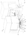
- Fig. 1 schematically two consecutive presses 10,12 a press line are shown. Between the presses, a robot 14 of the inventive design for transporting a pressing part 16 of the first press 10 is arranged in the subsequent second press 12.
- the press 10 thus comprises a removal position 18 on the lower half 20 of a pressing tool 22, while the second press 12 comprises a storage position 24 on the lower half 26 of its pressing tool 28.
- the robot 14 is provided to remove the pressing member 16 after the pressing operation in the first press 10 from the removal position 18 and to transport it to the storage position 24 of the second press 12.
- the robot 14 for this purpose comprises a horizontal side member 30 which extends in the space between the two presses 10,12.
- a horizontal slide 34 between the ends of the longitudinal member 30 is movable.
- a vertically movable vertical slide 36 is mounted, which has a carrier 38 at its lower end.
- the carrier 38 in turn carries an additional arm 40, which is displaceable on the one hand relative to the carrier 38 in the longitudinal direction of the additional arm 40 and on the other hand about the vertical axis of the carrier 38 is pivotable.
- a tool suspension 42 is provided at the end of the additional arm 40 in a manner which will be described in more detail below and which is tiltable and pivotable about different axes.
- the tool suspension 42 carries a tool 44 for receiving the pressing part 16. Due to the movement mechanism, by the horizontal side member 30, the horizontal slide 34 and the Vertical slide 36 is formed, the tool suspension 42 can reach virtually any point in the space between the presses 10,12 between the removal position 18 and the support position 24.
- Fig. 1 While in Fig. 1 an intermediate position is shown, in which the additional arm 40 is perpendicular to the longitudinal member 30, provides Fig. 2 an extremely extended position of the additional arm 40, in which the pressing member 16 is removed from the first press 10, while Fig. 3 a position between the position Fig. 2 and those out Fig. 1 represents, in which the additional arm 40 is partially retracted in the direction of the carrier 38, but is still largely aligned in the longitudinal direction with the side rail 30 before moving into the position in Fig. 1 is pivoted. In the further movement sequence for introducing the pressing part 16 in the subsequent press 12, the additional arm 40 is further pivoted in the same direction and extended with respect to the carrier 38, so that the storage position 24 is achieved for the pressing member 16.
- Fig. 4 shows an extended portion of the additional arm 40 which is held on the carrier 38.
- the end 46 of the additional arm 40 carries a hinge piece 48 which is fork-shaped and with respect to the fixed end 46 of the additional arm 40 is pivotable about a vertical axis A0.
- the pivoting range of the joint 48 is limited by lateral stops 50,52, which are formed by vertical side walls of the hollow profile, which form the additional arm 40.
- a non-illustrated motor drive is provided for pivoting the joint 48.
- the fork-shaped joint 48 has at its free end on two parallel flat legs 54,56. Between the legs 54,56 a pivot bearing 58 is enclosed for rotatably supporting the tool suspension 42.
- the bearing 58 itself is pivotable between the legs 54,56 of the Held joint 48 and can be pivoted about a horizontal axis A1, which is perpendicular to the axis of rotation A2 of the tool 42.
- This pivot axis A1 of the bearing 58 will be referred to below as the first axis A1, while the axis of rotation A2 of the tool suspension 42 should be referred to as the second axis.
- the pivoting of the bearing 58 between the legs 54,56 is achieved by motor drives 62,64, which are mounted laterally on the outside of the legs 54,56.
- To rotate the tool suspension 42 is another motor drive 66 on the second axis A2 between the legs 54,56.
- the tool suspension 42 comprises a pin 68 which rests with one end in the bearing 58. From the remaining free end of the pin 68 go laterally rod-shaped tool holders 70,72, the rod axes lie on a common third axis A3, which is perpendicular to the second axis A2.
- the tool holders 70,72 are rotatably mounted on the pin 68 about the third axis A3. The rotation takes place in each case via a rotary drive 74, 76, by means of which the respective tool holders 70, 72 can be rotated relative to the pin 68.
- Each of the tool holders 70, 72 carries part of a tool for lifting the pressing part 16.
- the tool suspension 42 itself can be rotated about the first axis A1 and the second axis A2, so that the rod-shaped tool holders 70,72 can take any position in space, by the rotation of the tool holders 70,72 about the third axis A3 in addition the fitting part 16 are aligned.
- This provides a large number of degrees of freedom in the movement of the pressing part 16.
- the tool suspension 42, the in Fig. 4 assume flat position in which all three axes A1, A2 and A3 lie in a common horizontal plane and the rod-shaped tool holders 70,72 are aligned by rotation about the third axis A3 so that the pressing member 16 is also horizontal. In this position, the pressing member 16 can also be introduced into a gap between the tool halves of a press 10,12, which is dimensioned relatively low.
- the tool suspension 42 can be converted into a position, as for example in Fig. 5B is shown.
- the Figs. 5A and 5B represent side views of the present embodiment of the invention Robot in two different positions of the tool suspension 42, namely those already associated with Fig. 2 shown position according to Fig. 5A and the position according to Fig. 5B according to the Fig. 1 and 3 ,
- the third axis A3 as a bar axis of the tool holders 70,72 is hereby pivoted about the horizontal axis A1 parallel to the axis.
- Fig. 6 shows a situation in which the second axis A2 lies in the horizontal plane and in which the tool holders 70,72 about their rod axes, namely the third axis A3, are rotated such that the pressing member 16 is vertical.
- Such a position may be useful in cases where the pressing member 16 must be taken from or placed in a vertical position.
- the pressing member 16 can assume almost any position, depending on the spatial conditions between the press stations.
- Fig. 6 The situation off Fig. 6 is also in Fig. 7 again shown in perspective. It can be clearly seen that the rod-shaped tool holders 70, 72 with respect to the position Fig. 4 take a rotated position by 90 ° on the pin 68 of the tool suspension 42, so that the vertical position of the pressing member 16 is achieved.
Landscapes
- Engineering & Computer Science (AREA)
- Mechanical Engineering (AREA)
- Robotics (AREA)
- Manipulator (AREA)
- Mounting, Exchange, And Manufacturing Of Dies (AREA)
Description
- Die Erfindung betrifft einen Roboter mit einem Bewegungsmechanismus zum Umsetzen von Pressteilen, insbesondere zwischen zwei aufeinanderfolgenden Pressen einer Pressenstraße, die die Durchführung von dreidimensionalen Bewegungen auf dem Weg zwischen den Pressen gestattet.
- Roboter sind in großer Zahl bekannt. Bei einigen Robotern besteht der schwenkbare Roboterarm wenigstens aus zwei Gliedern, die um eine waagerechte Achse in bezug aufeinander schwenkbar verbunden sind. Durch diese Schwenk- oder Knickbewegung kann der Abstand vom äußeren Ende des Roboterarms zum Fuß verkürzt und verlängert werden. Im übrigen kann die Höhe des äußeren Endes des Roboterarms durch geeignete Schwenkbewegung der beiden Armteile um ihre waagerechten Schwenkachsen verändert werden.
- Beim Umsetzen von Pressteilen zwischen zwei Pressen muß berücksichtigt werden, dass die Platzverhältnisse zwischen den Pressen beengt sind und zudem der zwischen dem Oberwerkzeug und dem Unterwerkzeug einer Presse zur Verfügung stehende Raum sehr niedrig sein kann. Es ist daher häufig problematisch, relativ große Pressteile von einer Presse in die nächste zu bewegen. Werden hierzu Roboter der oben genannten Art verwendet, die einknickbare Arme aufweisen, sind sowohl die Ständer der benachbarten Pressen als auch der Fuß des Roboters selbst hinderlich, zumal der Roboterarm während der Schwenkbewegung mit seinem äußeren Ende eine Kreisbogenbahn beschreibt und sich den Pressenständern annähert.
- Darüber hinaus besteht ein bauartbedingtes Problem derartiger Roboter darin, das der Bewegungsablauf beim Umsetzen der Pressteile verhältnismäßig zeitaufwändig und energieintensiv ist.
- Neben den genannten Robotern mit Schwenkarm sind auch relativ einfach aufgebaute Linearroboter bekannt, die zwischen den Pressen eine relativ einfache lineare Bewegung ausführen können. Die bisher bekannten Linearroboter weisen jedoch wenige Freiheitsgrade in der Bewegung der Pressteile auf und sind daher für den hier vorliegenden Einsatzzweck in einer Pressenstraße eher ungeeignet. Sowohl Schwenkarm-Roboter als auch Linearroboter weisen bisher das Problem auf, dass die Werkzeugaufhängung am Ende des Roboterarms eine Bauhöhe aufweist, die das Einführen von Pressteilen in einen relativ niedrigen Raum innerhalb der Presse erschwert.
- Aus der
DE-A-3804572 ist ein Roboter zum Umsetzen von Pressteilen bekannt, der einen horizontalen Längsträger als Bewegungsmechanismus umfasst, an welchem ein senkrechter Träger horizontal verfahrbar ist, an dem ein horizontaler Zusatzaren angebracht ist, der um die senkrechte Achse des Trägers schwenkbar ist und an dessen äußeren Ende eine Werkzeugaufhängung vorgesehen ist, die eine die Werkzeugaufnahme umfasst und im mehrere Achsen dreh- bzw. schwenkbar ist. - Der Erfindung liegt daher die Aufgabe zugrunde, einen Roboter zum Umsetzen von Pressteilen zu schaffen, der eine Bewegung des Pressteils mit möglichst vielen Freiheitsgraden mit geringem Zeit- und Energieaufwand ermöglicht. Insbesondere soll das Umsetzen des Pressteils auf beengtem Raum zwischen den Pressen und ein Einführen des Endes des Roboterarms in einem sehr niedrigen Pressenraum zwischen den Presswerkzeugen ermöglicht werden.
- Diese Aufgabe wird erfindungsgemäß durch einen Roboter mit den Merkmalen des Anspruchs 1 gelöst.
- Erfindungsgemäß ist an dem Bewegungsmechanismus des Robotors ein Zusatzarm angebracht, der mit dem Bewegungsmechanismus über einen Träger verbunden ist, der eine senkrechte Achse aufweist und der eine Schwenkung des Zusatzarms um diese senkrechte Achse des Trägers sowie eine Längsverschiebung des Zusatzarms bezüglich des Trägers gestattet. Diese Schwenkbarkeit in Verbindung mit der Ausfahrbarkeit des Zusatzarms gegenüber dem eigentlichen Roboterarm gestattet eine hohe Beweglichkeit. Insbesondere kann der Abstand zwischen der Werkzeugaufnahme und der Basis des Roboters durch das lineare Ein- und Ausfahren in einfacher Weise verkürzt oder verlängert werden, ohne dass der Roboterarm eingeknickt oder auf sonstige Weise selbst bewegt werden muß.
- Am äußeren Ende des Zusatzarms ist eine Werkzeugaufhängung vorgesehen, die um eine horizontale erste Achse und um eine zweite Achse schwenkbar ist, die zur ersten Achse senkrecht steht. Damit ist die Werkzeugaufhängung frei im Raum bewegbar, so dass sich eine relativ freie Positionierbarkeit des Pressteils ergibt, das am Werkzeug aufgehängt ist. Die eigentliche Werkzeugaufnahme der Werkzeugaufhängung ist zusätzlich um eine dritte Achse drehbar, die zu der zweiten Achse senkrecht steht. Hierdurch ergeben sich noch zusätzliche Bewegungsmöglichkeiten des Werkzeugs an der Werkzeugaufhängung.
- Insbesondere ist es möglich, die zweite Achse der Werkzeugaufhängung durch Schwenken um die horizontale erste Achse in eine horizontale Stellung zu kippen und die Werkzeugaufnahme durch Schwenken um die zweite Achse ebenfalls in die horizontale Ebene zu stellen, so dass alle drei Achsen in der gleichen horizontalen Ebene liegen. In dieser Stellung weist das Ende des Zusatzarms einschließlich der Werkzeugaufhängung mit der Werkzeugaufnahme eine relativ geringe Bauhöhe auf und ermöglicht somit ein Einführen des Pressteils in einen flachen Pressenraum. Dieses Einführen kann im wesentlichen durch ein lineares Ausfahren des Zusatzarms an dessen Träger erfolgen.
- Während die erfindungsgemäße Konstruktion beim Entnehmen bzw. beim Einlegen des Pressteils in die Presse Vorteile bezüglich der Bauhöhe bietet, kann das Pressteil durch die große Zahl der vorhandenen Freiheitsgrade im Raum zwischen den Pressen frei gedreht und gekippt werden, zusätzlich zu einer Linearbewegung durch den Zusatzarm auf die Roboterbasis zu oder von dieser weg. Die entsprechenden Bewegungsabläufe können mit verringertem Zeit- und Energieaufwand durchgeführt werden.
- Vorzugsweise ist die Werkzeugaufhängung in einem Schwenklager zur Drehung um die zweite Achse gelagert, welches Schwenklager um die erste Achse schwenkbar am Ende des Zusatzarmes gehalten wird.
- Die Werkzeugaufnahme ist vorzugsweise als stabförmiger Halter ausgebildet, dessen Stabachse die dritte Achse bildet.
- Gemäß einer bevorzugten Ausführungsform der vorliegenden Erfindung umfaßt das Ende des Zusatzarms ein Gelenkstück, das um eine senkrechte Achse schwenkbar ist und in dessen Ende die dritte Achse gelagert ist.
- Durch dieses Gelenkstück kann die Werkzeugaufhängung auch in einer Stellung zum Einfahren in den Pressenraum, in welcher die erste, zweite und dritte Achse in einer gemeinsamen horizontalen Ebene liegen, schwenkbar am Ende des Zusatzarms gehalten werden. Dieses Verschwenken in der horizontalen Ebene um die Achse des Gelenkstücks kann einen leichten Winkelversatz der Stellung des Zusatzarms bezüglich der Einführungsrichtung ermöglichen.
- Das Gelenkstück ist vorzugsweise gabelförmig ausgebildet und umgreift das Schwenklager.
- Gemäß einer weiteren bevorzugten Ausführungsform umfaßt der Bewegungsmechanismus einen horizontalen Längsträger, an welchem der Träger entlang der Länge des Längsträgers und in vertikaler Richtung verfahrbar gehalten wird.
- Der Längsträger dient somit dazu, eine längere Wegstrecke im Zwischenraum zwischen den beiden zu bedienenden Pressen zu überbrücken. Zwischen den Enden des horizontalen Längsträgers wird der Träger für den Zusatzarm hin- und hergefahren und kann in der jeweiligen Endstellung die oben beschriebenen Bewegungsabläufe zum Einführen oder Entnehmen von Pressteilen ausführen.
- Gemäß einer weiteren bevorzugten Ausführungsform umfaßt der Bewegungsmechanismus einen um eine senkrechte Achse schwenkbaren mehrteiligen und einknickbaren Arm, wobei der Träger am Ende dieses Roboterarms angebracht ist.
- Durch den Zusatzarm werden die oben beschriebenen Nachteile des einknickbaren Roboterarms zumindest teilweise kompensiert, da durch den flach gehaltenen Zusatzarm die Gefahr einer Kollision der eingeknickten Teile des Roboterarms mit den Stützen der Presse vermindert wird.
- Bevorzugt sind zur Durchführung der Schwenkung um die erste Achse, die zweite Achse und/oder die dritte Achse einer oder mehrere Motoren vorgesehen.
- Im folgenden wird ein bevorzugtes Ausführungsbeispiel der Erfindung anhand der Zeichnung näher erläutert.
- Fig. 1 bis 3
- zeigen ein Ausführungsbeispiel des erfindungsgemäßen Roboters in einer Pressenstraße;
- Fig. 4
- ist eine perspektivische Detailansicht des Roboters aus den
Fig. 1 bis 3 ; - Fig. 5A und 5B
- sind Seitenansichten der dargestellten Ausführungsform des erfindungsgemäßen Roboters in zwei verschiedenen Stellungen der Werkzeugaufnahme und
- Fig. 6 und 7
- sind eine Seitenansicht und eine perspektivische Ansicht des erfindungsgemäßen Roboters in einer weiteren Stellung der Werkzeugaufnahme.
- In
Fig. 1 sind schematisch zwei aufeinanderfolgende Pressen 10,12 einer Pressenstraße dargestellt. Zwischen den Pressen ist ein Roboter 14 erfindungsgemäßer Bauart zum Transport eines Pressteils 16 von der ersten Presse 10 in die nachfolgende zweite Presse 12 angeordnet. Die Presse 10 umfaßt demnach eine Entnahmeposition 18 auf der unteren Hälfte 20 eines Presswerkzeugs 22, während die zweite Presse 12 eine Ablageposition 24 auf der unteren Hälfte 26 ihres Presswerkzeugs 28 umfaßt. Der Roboter 14 ist dazu vorgesehen, das Pressteil 16 nach dem Pressvorgang in der ersten Presse 10 von der Entnahmeposition 18 zu entnehmen und in die Ablageposition 24 der zweiten Presse 12 zu transportieren. - Der Roboter 14 umfaßt zu diesem Zweck einen horizontalen Längsträger 30, der sich in dem Raum zwischen den beiden Pressen 10,12 erstreckt. An dem Längsträger 30 befinden sich Schienen 32, auf denen ein Horizontalschlitten 34 zwischen den Enden des Längsträgers 30 verfahrbar ist. An dem Horizontalschlitten 34 ist ein vertikal verfahrbarer Vertikalschlitten 36 angebracht, der an seinem unteren Ende einen Träger 38 aufweist. Der Träger 38 trägt wiederum einen Zusatzarm 40, der einerseits gegenüber dem Träger 38 in Längsrichtung des Zusatzarms 40 verschiebbar ist und andererseits um die senkrechte Achse des Trägers 38 schwenkbar ist.
- Am Ende des Zusatzarms 40 ist auf unten noch näher beschriebene Weise eine Werkzeugaufhängung 42 vorgesehen, die um verschiedene Achsen kippbar und schwenkbar ist. Die Werkzeugaufhängung 42 trägt ein Werkzeug 44 zur Aufnahme des Pressteils 16. Aufgrund des Bewegungsmechanismus, der durch den horizontalen Längsträger 30, den Horizontalschlitten 34 und den Vertikalschlitten 36 gebildet wird, kann die Werkzeugaufhängung 42 praktisch jeden beliebigen Punkt im Raum zwischen den Pressen 10,12 zwischen der Entnahmeposition 18 und der Auflageposition 24 erreichen.
- Während in
Fig. 1 eine Zwischenposition dargestellt ist, in welcher der Zusatzarm 40 senkrecht zum Längsträger 30 steht, stelltFig. 2 eine extrem ausgefahrene Stellung des Zusatzarms 40 dar, in welcher das Pressteil 16 aus der ersten Presse 10 entnommen wird, währendFig. 3 eine Position zwischen der Stellung ausFig. 2 und derjenigen ausFig. 1 darstellt, in welcher der Zusatzarm 40 teilweise in Richtung Träger 38 eingefahren ist, jedoch noch weitgehend in Längsrichtung mit dem Längsträger 30 ausgerichtet ist, bevor er in die Stellung inFig. 1 verschwenkt wird. Im weiteren Bewegungsablauf zum Einführen des Pressteils 16 in die nachfolgende Presse 12 wird der Zusatzarm 40 weiter im gleichen Drehsinn geschwenkt und bezüglich des Trägers 38 ausgefahren, so dass die Ablageposition 24 für das Pressteil 16 erreicht wird. - In
Fig. 2 ist ersichtlich, dass die Werkzeugaufhängung 42 am Ende des Zusatzarms 40 im Pressenraum der ersten Presse 10 zwischen den Hälften des Presswerkzeugs 22 eine andere Stellung einnimmt als in denFig. 1 und3 . Diese Veränderung der Stellung der Werkzeugaufnahme wird durch eine Konstruktion ermöglicht, die im Detail im Zusammenhang mitFig. 4 beschrieben werden soll. -
Fig. 4 zeigt einen ausgefahrenen Teil des Zusatzarms 40, der am Träger 38 gehalten wird. Das Ende 46 des Zusatzarms 40 trägt ein Gelenkstück 48, das gabelförmig ausgebildet ist und gegenüber dem festen Ende 46 des Zusatzarms 40 um eine senkrechte Achse A0 schwenkbar ist. Der Schwenkbereich des Gelenkstücks 48 wird durch seitliche Anschläge 50,52 begrenzt, die durch senkrechte Seitenwände des Hohlprofils gebildet werden, die den Zusatzarm 40 bilden. Zum Verschwenken des Gelenkstücks 48 ist ein nicht näher dargestellter Motorantrieb vorgesehen. - Das gabelförmige Gelenkstück 48 weist an seinem freien Ende zwei parallele flache Schenkel 54,56 auf. Zwischen den Schenkeln 54,56 wird ein Schwenklager 58 zur drehbaren Lagerung der Werkzeugaufhängung 42 eingefaßt. Das Lager 58 selbst ist schwenkbar zwischen den Schenkeln 54,56 des Gelenkstücks 48 gehalten und kann um eine horizontale Achse A1 geschwenkt werden, die zu der Rotationsachse A2 der Werkzeughängung 42 senkrecht steht. Diese Schwenkachse A1 des Lagers 58 soll im folgenden als erste Achse A1 bezeichnet werden, während die Rotationsachse A2 der Werkzeugaufhängung 42 als zweite Achse bezeichnet werden soll. Das Schwenken des Lagers 58 zwischen den Schenkeln 54,56 wird durch Motorantriebe 62,64 erreicht, die seitlich außen an den Schenkeln 54,56 angebracht sind. Zum Drehen der Werkzeugaufhängung 42 dient ein weiterer Motorantrieb 66 auf der zweiten Achse A2 zwischen den Schenkeln 54,56.
- Die Werkzeugaufhängung 42 umfaßt einen Zapfen 68, der mit einem Ende im Lager 58 einliegt. Vom verbleibenden freien Ende des Zapfens 68 gehen seitlich stabförmige Werkzeugaufnahmen 70,72 aus, deren Stabachsen auf einer gemeinsamen dritten Achse A3 liegen, die senkrecht zur zweiten Achse A2 steht. Die Werkzeugaufnahmen 70,72 sind um die dritte Achse A3 drehbar am Zapfen 68 angebracht. Die Drehung erfolgt jeweils über einen Rotationsantrieb 74,76, durch welchen die jeweilige Werkzeugaufnahmen 70,72 gegenüber dem Zapfen 68 gedreht werden können. Jede der Werkzeugaufnahmen 70,72 trägt einen Teil eines Werkzeugs zum Anheben des Pressteils 16.
- Während die Werkzeugaufhängung 42 selbst um die erste Achse A1 und die zweite Achse A2 gedreht werden kann, so dass die stabförmigen Werkzeugaufnahmen 70,72 eine beliebige Stellung im Raum einnehmen können, kann durch die Rotation der Werkzeugaufnahmen 70,72 um die dritte Achse A3 zusätzlich das Passteil 16 ausgerichtet werden. Dies schafft eine große Anzahl von Freiheitsgraden bei der Bewegung des Pressteils 16. Ferner kann die Werkzeugaufhängung 42 die in
Fig. 4 gezeigte flache Stellung einnehmen, in welcher alle drei Achsen A1, A2 und A3 in einer gemeinsamen horizontalen Ebene liegen und die stabförmigen Werkzeugaufnahmen 70,72 durch Drehen um die dritte Achse A3 so ausgerichtet sind, dass das Pressteil 16 ebenfalls horizontal liegt. In dieser Stellung läßt sich das Pressteil 16 auch in einen Zwischenraum zwischen den Werkzeughälften einer Presse 10,12 einführen, der relativ niedrig bemessen ist. - Aus dieser Stellung läßt sich die Werkzeugaufhängung 42 in eine Stellung überführen, wie sie beispielsweise in
Fig. 5B gezeigt ist. DieFig. 5A und 5B repräsentieren Seitenansichten der vorliegenden Ausführungsform des erfindungsgemäßen Roboters in zwei verschiedenen Stellungen der Werkzeugaufhängung 42, nämlich die bereits im Zusammenhang mitFig. 2 gezeigte Stellung gemäßFig. 5A und die Stellung gemäßFig. 5B entsprechend denFig. 1 und3 . - Wird aus der Stellung in
Fig. 5A , in der die zweite Achse A2 horizontal liegt, die Werkzeugaufhängung 42 um die erste Achse A1 geschwenkt, so dass die zweite Achse A2 senkrecht steht, wird die Stellung gemäßFig. 5B erreicht. Es ist deutlich erkennbar, dass in der Stellung derFig. 5B die Werkzeugaufhängung 42 eine wesentlich größere Bauhöhe aufweist, als in der vorhergehenden Stellung gemäßFig. 5A . Daher ist die flache Stellung ausFig. 5A bevorzugt dazu geeignet, ein Pressteil 16 in eine Presse 10,12 einzuführen oder aus dieser zu entnehmen. Bei der Überführung von der Position ausFig. 5A in die Position ausFig. 5B kann die horizontale Lage des Pressteils 16 beibehalten werden, und zwar dank der Drehbarkeit der stabförmigen Werkzeugaufnahmen 70,72 um die dritte Achse A3, die die Rotation um die erste Achse A1 kompensiert. Die dritte Achse A3 als Stabachse der Werkzeugaufnahmen 70,72 wird hierbei um die horizontale erste Achse A1 achsparallel verschwenkt. - Die erfindungsgemäße Achskonstruktion der Werkzeugaufhängung 42 bietet noch weitere Anwendungsmöglichkeiten.
Fig. 6 zeigt eine Situation, in welcher die zweite Achse A2 in der horizontalen Ebene liegt und in der die Werkzeugaufnahmen 70,72 um ihre Stabachsen, nämlich die dritte Achse A3, derart gedreht sind, dass das Pressteil 16 senkrecht steht. Eine solche Stellung kann in Fällen nützlich sein, in welchen das Pressteil 16 aus einer senkrechten Stellung angenommen oder in diese abgelegt werden muß. Während der Überführung von einer Position in die andere kann das Pressteil 16 naturgemäß nahezu jede mögliche Stellung einnehmen, in Abhängigkeit von den räumlichen Gegegebenheiten zwischen den Pressenstationen. - Die Situation aus
Fig. 6 ist auch inFig. 7 nochmals perspektiv dargestellt. Deutlich ist zu erkennen, dass die stabförmigen Werkzeugaufnahmen 70, 72 gegenüber der Stellung ausFig. 4 eine um 90° gedrehte Stellung am Zapfen 68 der Werkzeugaufhängung 42 einnehmen, so dass die senkrechte Stellung des Pressteils 16 erreicht wird.
Claims (8)
- Roboter (14) mit einem Bewengunsgmechanismus zum Umsetzen von Pressteilen, insbesondere zwischen zwei aufeinanderfolgenden Pressen (10,12) einer Pressenstraße, die die Durchführung von dreidimensionalen Bewegungen auf dem Weg zwischen den Pressen (10,12) gestattet, wobei an dem Bewegungsmechanismus ein horizontaler Zusatzarm (40) angebracht ist, der mit dem Bewegungsmechanismus über einen Träger (38) verbunden ist, der eine senkrechte Achse aufweist und der eine Schwenkung des Zusatzarms (40) um diese senkrechte Achse des Trägers (38) sowie eine horizontale Längsverschiebung des Zusatzarms (40) in Bezug auf den Träger (38) gestattet, wobei am äußeren Ende des Zusatzarmes (40) eine Werkzeugaufhängung (42) vorgesehen ist, die um eine horizontale erste Achse (A1) und um eine zweite Achse (A2) schwenkbar ist, die zur ersten Achse (A1) senkrecht steht,
wobei die Werkzeugaufhängung (42) eine Werkzeugaufnahme (70,72) umfasst, die
um eine dritte Achse (A3) senkrecht zur zweiten Achse (A2) drehbar ist, und wobei sich die erste Achse (A1), die zweite Achse (A2) und die dritte Achse (A3) in eine gemeinsame horizontale Ebene bringen lassen. - Roboter nach Anspruch 1, dadurch gekennzeichnet, dass die Werkzeugaufhängung (42) in einem Schwenklager (58) zur Drehung um die zweite Achse (A2) gelagert ist, welches Schwenklager (58) um die erste Achse (A1) schwenkbar am Ende des Zusatzarmes (40) gehalten wird.
- Roboter nach Anspruch 1 oder 2, dadurch gekennzeichnet, dass die Werkzeugaufnahme (70,72) als stabförmiger Halter ausgebildet ist, dessen Stabachse die dritte Achse (A3) bildet.
- Roboter nach einem der vorhergehenden Ansprüche, dadurch gekennzeichnet, dass das Ende des Zusatzarms (40) ein Gelenkstück (48) umfasst, das um eine senkrechte Achse (A0) schwenkbar am Zusatzarm (40) angebracht ist und an dessen Ende die dritte Achse (A3) gelagert ist.
- Roboter nach Anspruch 4 in Verbindung mit Anspruch 2 oder 3, dadurch gekennzeichnet, dass das Gelenkstück (48) gabelförmig ausgebildet ist und das Schwenklager (58) beidseitig umgreift.
- Roboter nach einem der Ansprüche 1 bis 5, dadurch gekennzeichnet, dass der Bewegungsmechanismus einen horizontalen Längsträger (30) umfasst, an welchem der Träger (38) entlang der Länge des Längsträgers (30) und in vertikaler Richtung verfahrbar gehalten wird.
- Roboter nach einem der Ansprüche 1 bis 5, dadurch gekennzeichnet, dass der Bewegungsmechanismus einen um eine senkrechte Achse schwenkbaren mehrteiligen und einknickbaren Arm aufweist und dass der Träger am Ende dieses Armes angebracht ist.
- Roboter nach einem der vorhergehenden Ansprüche, dadurch gekennzeichnet, dass zur Durchführung der Schwenkung um die erste Achse (A1), die zweite Achse (A2) und/oder die dritte Achse (A3) einer oder mehrere Motoren vorgesehen sind.
Applications Claiming Priority (1)
| Application Number | Priority Date | Filing Date | Title |
|---|---|---|---|
| PCT/EP2009/067682 WO2011076249A1 (de) | 2009-12-21 | 2009-12-21 | Roboter |
Publications (2)
| Publication Number | Publication Date |
|---|---|
| EP2516116A1 EP2516116A1 (de) | 2012-10-31 |
| EP2516116B1 true EP2516116B1 (de) | 2013-11-27 |
Family
ID=41727817
Family Applications (1)
| Application Number | Title | Priority Date | Filing Date |
|---|---|---|---|
| EP09803758.3A Not-in-force EP2516116B1 (de) | 2009-12-21 | 2009-12-21 | Roboter mit zusatzarm |
Country Status (6)
| Country | Link |
|---|---|
| US (1) | US8920108B2 (de) |
| EP (1) | EP2516116B1 (de) |
| CN (1) | CN103328165B (de) |
| BR (1) | BR112012015640B1 (de) |
| ES (1) | ES2445702T3 (de) |
| WO (1) | WO2011076249A1 (de) |
Cited By (1)
| Publication number | Priority date | Publication date | Assignee | Title |
|---|---|---|---|---|
| DE102017121556A1 (de) * | 2017-09-18 | 2019-03-21 | Strothmann Machines & Handling GmbH | Fördergerät zum Umsetzen von Pressteilen |
Families Citing this family (25)
| Publication number | Priority date | Publication date | Assignee | Title |
|---|---|---|---|---|
| CN203599023U (zh) * | 2013-11-06 | 2014-05-21 | 富鼎电子科技(嘉善)有限公司 | 静置线烤箱 |
| JP2016036880A (ja) * | 2014-08-08 | 2016-03-22 | 村田機械株式会社 | ワーク搬送装置及び工作機械 |
| US10392203B2 (en) | 2015-12-31 | 2019-08-27 | ROI Industries Group, Inc. | Compact dual palletizer including a skeleton and a subassembly |
| US9511957B1 (en) * | 2015-12-31 | 2016-12-06 | ROI Industries Group, Inc. | Compact palletizer including a skeleton and a subassembly |
| US10676292B2 (en) | 2015-12-31 | 2020-06-09 | ROI Industries Group, Inc. | Compact palletizer including a skeleton, subassembly, and stretch wrap system |
| US10287112B2 (en) | 2015-12-31 | 2019-05-14 | ROI Industries Group, Inc. | Compact palletizer including a skeleton, subassembly, and stretch wrap system |
| ITUB20160440A1 (it) * | 2016-01-28 | 2017-07-28 | Unitec Spa | Gruppo di trasferimento di prodotti ortofrutticoli, e relativo procedimento. |
| CN109996619B (zh) * | 2016-11-27 | 2021-03-30 | 毕晓普操纵技术私人股份公司 | 用于锻造转向齿条的模具设备 |
| JP6571703B2 (ja) * | 2017-02-13 | 2019-09-04 | ファナック株式会社 | 搬送用ツール |
| CN107159803A (zh) * | 2017-05-23 | 2017-09-15 | 广州市铮宝精密机械有限公司 | 冲压机器人自动上下料系统 |
| JP6618957B2 (ja) * | 2017-06-14 | 2019-12-11 | アイダエンジニアリング株式会社 | プレス機械のワーク搬送装置 |
| CN109967921A (zh) * | 2017-12-28 | 2019-07-05 | 上汽通用五菱汽车股份有限公司 | 一种四轴六自由度白车身前侧板辅助定位装置 |
| JP6693978B2 (ja) | 2018-01-23 | 2020-05-13 | ファナック株式会社 | 搬送用ツールおよびロボット |
| US12128470B2 (en) * | 2018-02-14 | 2024-10-29 | Langenstein & Schemann Gmbh | Production system, production module, method for operating and setting up a production line, and method for producing a workpiece |
| CN109502332A (zh) * | 2018-11-23 | 2019-03-22 | 晋城鸿刃科技有限公司 | 下料装置 |
| EP3718659B1 (de) * | 2019-04-05 | 2022-11-23 | Horstkemper Maschinenbau GmbH | Automationsgerät |
| DE102019119228B4 (de) * | 2019-07-16 | 2024-07-18 | Strothmann Machines & Handling GmbH | Linearförderer zum Umsetzen von Werkstücken zwischen zwei in einer Durchlaufrichtung aufeinanderfolgenden Positionen |
| US11660649B2 (en) * | 2019-08-14 | 2023-05-30 | Accurpress America Inc. | Press brake system |
| CN110883250A (zh) * | 2019-12-03 | 2020-03-17 | 新昌县维利机械有限公司 | 一种铝合金冲压件的下料装置 |
| CN111846932A (zh) * | 2020-07-26 | 2020-10-30 | 肖祎 | 一种智能制造柔性生产线的自动上料装置 |
| EP4201551B1 (de) * | 2021-12-27 | 2024-05-15 | Fagor Arrasate, S.Coop. | Fördervorrichtung für eine pressenanlage |
| DE202022101489U1 (de) * | 2022-03-22 | 2022-05-10 | R + S Automotive GmbH | Transportvorrichtung für das Überführen eines Materialzuschnitts und eine Anordnung zur Herstellung von Verbundbauteilen |
| EP4522355A1 (de) * | 2022-05-10 | 2025-03-19 | Fagor Arrasate, S.Coop. | Fertigungsstrasse zur bearbeitung von flachformatteilen zu formteilen |
| IT202200020901A1 (it) * | 2022-10-11 | 2024-04-11 | Scm Group Spa | Macchina robotizzata e dispositivo manipolatore. |
| CN116176000B (zh) * | 2023-04-07 | 2023-11-03 | 常州新创航空科技有限公司 | 一种碳纤维片材搬运设备、制造系统及制造方法 |
Family Cites Families (13)
| Publication number | Priority date | Publication date | Assignee | Title |
|---|---|---|---|---|
| GB781465A (en) * | 1954-03-29 | 1957-08-21 | Cyril Walter Kenward | Improvements in or relating to positioning, assembling or manipulating apparatus |
| AT363298B (de) * | 1978-12-18 | 1981-07-27 | Igm Ind Geraete Maschf Gmbh | Schweissautomat |
| US4132318A (en) * | 1976-12-30 | 1979-01-02 | International Business Machines Corporation | Asymmetric six-degree-of-freedom force-transducer system for a computer-controlled manipulator system |
| US4907937A (en) * | 1985-07-08 | 1990-03-13 | Ford Motor Company | Non-singular industrial robot wrist |
| DE3804572A1 (de) | 1988-02-13 | 1989-08-24 | Rudolf Sappel | Blechteilebefoerderungseinrichtung in pressenstrassen |
| CH677745A5 (de) * | 1988-02-15 | 1991-06-28 | Amada Co Ltd | |
| IT1237707B (it) * | 1989-12-20 | 1993-06-15 | Prima Ind Spa | Struttura di macchina operatrice |
| SE9202982D0 (sv) * | 1992-10-12 | 1992-10-12 | Anders Sjoeberg | Plaatklippning |
| IT1272084B (it) * | 1993-12-17 | 1997-06-11 | Comau Spa | Robot industriale, particolarmente per la movimentazione di pezzi da una pressa all'altra in una linea di presse |
| DE20306257U1 (de) * | 2003-04-17 | 2004-08-19 | Kuka Schweissanlagen Gmbh | Bearbeitungsvorrichtung |
| DE102004048036A1 (de) * | 2004-09-28 | 2006-04-06 | Ras Reinhardt Maschinenbau Gmbh | Biegeeinrichtung |
| US7309204B2 (en) * | 2005-12-20 | 2007-12-18 | Schuler Automation Gmbh & Co. Kg | Articulated arm robot |
| FR2906490B1 (fr) * | 2006-10-03 | 2008-12-12 | Fanuc Robotics Europ | Robot industriel, notamment pour le transfert de pieces entre deux presses. |
-
2009
- 2009-12-21 CN CN200980162936.1A patent/CN103328165B/zh not_active Expired - Fee Related
- 2009-12-21 EP EP09803758.3A patent/EP2516116B1/de not_active Not-in-force
- 2009-12-21 WO PCT/EP2009/067682 patent/WO2011076249A1/de not_active Ceased
- 2009-12-21 BR BR112012015640-3A patent/BR112012015640B1/pt not_active IP Right Cessation
- 2009-12-21 ES ES09803758.3T patent/ES2445702T3/es active Active
- 2009-12-21 US US13/516,773 patent/US8920108B2/en not_active Expired - Fee Related
Cited By (1)
| Publication number | Priority date | Publication date | Assignee | Title |
|---|---|---|---|---|
| DE102017121556A1 (de) * | 2017-09-18 | 2019-03-21 | Strothmann Machines & Handling GmbH | Fördergerät zum Umsetzen von Pressteilen |
Also Published As
| Publication number | Publication date |
|---|---|
| US8920108B2 (en) | 2014-12-30 |
| CN103328165A (zh) | 2013-09-25 |
| ES2445702T3 (es) | 2014-03-04 |
| BR112012015640B1 (pt) | 2020-09-29 |
| CN103328165B (zh) | 2015-10-21 |
| US20120282066A1 (en) | 2012-11-08 |
| EP2516116A1 (de) | 2012-10-31 |
| WO2011076249A1 (de) | 2011-06-30 |
Similar Documents
| Publication | Publication Date | Title |
|---|---|---|
| EP2516116A1 (de) | Roboter | |
| DE69710444T2 (de) | Vorrichtung zum Laden von Rohren auf Bearbeitungsmaschinen, insbesondere auf Rohrbiegemaschinen | |
| EP0671228B1 (de) | Transporteinrichtung für Werkstücke in einer Presse | |
| EP3403738B1 (de) | Blechbiegemaschine | |
| EP0672480A1 (de) | Transportsystem | |
| DE102015206914A1 (de) | Werkzeugmaschine | |
| DE10235191A1 (de) | Roboter | |
| EP1819480B1 (de) | Werkstückpositionierer | |
| EP2117781B1 (de) | Manipulator für die beladung wenigstens einer maschine, insbesondere werkzeugmaschine, sowie beladevorrichtung für eine derartige maschine | |
| DE112006001920B4 (de) | Parallelkinematische Vorrichtung mit Mitteln zur Kompensation der Haltekraft | |
| DE3404553C2 (de) | Handhabungseinrichtung, insbesondere zum Be- und Entladen von Werkzeugmaschinen | |
| WO2005075123A1 (de) | Transportvorrichtung für werkstücke durch pressenanlagen | |
| EP1064110A1 (de) | Biegemaschine | |
| EP2289665B1 (de) | Werkzeugmaschine mit einer Werkzeugwechselvorrichtung | |
| DE19901794A1 (de) | Biegemaschine | |
| DE19710171C2 (de) | Manipulator mit Parallelstruktur | |
| DE69901310T2 (de) | Greifer zum wechseln von biegewerkzeugen für eine rohrbiegemaschine | |
| DE102012008559B4 (de) | Roboterarm-Modul für einen Roboterarm bzw. Roboterarm | |
| EP1366834B1 (de) | Werkzeugwechselvorrichtung für Pressen | |
| DE102017116716A1 (de) | Bearbeitungsanlage für Flugzeugstrukturbauteile | |
| DE10139807B4 (de) | Manipulationsvorrichtung | |
| DE2418317A1 (de) | Wickelmaschine fuer blechbaender zur bildung von bunden | |
| EP2134514B1 (de) | Manipulator für die beladung wenigstens einer maschine, insbesondere werkzeugmaschine, und beladevorrichtung für eine derartige maschine | |
| DE1652815B2 (de) | Fahrbarer Schmiedemanipulator | |
| EP1302302B1 (de) | Schweisseinrichtung |
Legal Events
| Date | Code | Title | Description |
|---|---|---|---|
| PUAI | Public reference made under article 153(3) epc to a published international application that has entered the european phase |
Free format text: ORIGINAL CODE: 0009012 |
|
| 17P | Request for examination filed |
Effective date: 20120523 |
|
| AK | Designated contracting states |
Kind code of ref document: A1 Designated state(s): AT BE BG CH CY CZ DE DK EE ES FI FR GB GR HR HU IE IS IT LI LT LU LV MC MK MT NL NO PL PT RO SE SI SK SM TR |
|
| DAX | Request for extension of the european patent (deleted) | ||
| GRAP | Despatch of communication of intention to grant a patent |
Free format text: ORIGINAL CODE: EPIDOSNIGR1 |
|
| INTG | Intention to grant announced |
Effective date: 20130419 |
|
| GRAS | Grant fee paid |
Free format text: ORIGINAL CODE: EPIDOSNIGR3 |
|
| GRAA | (expected) grant |
Free format text: ORIGINAL CODE: 0009210 |
|
| RAP1 | Party data changed (applicant data changed or rights of an application transferred) |
Owner name: STROTHMANN MACHINES & HANDLING GMBH |
|
| AK | Designated contracting states |
Kind code of ref document: B1 Designated state(s): AT BE BG CH CY CZ DE DK EE ES FI FR GB GR HR HU IE IS IT LI LT LU LV MC MK MT NL NO PL PT RO SE SI SK SM TR |
|
| REG | Reference to a national code |
Ref country code: GB Ref legal event code: FG4D Free format text: NOT ENGLISH |
|
| REG | Reference to a national code |
Ref country code: CH Ref legal event code: EP |
|
| REG | Reference to a national code |
Ref country code: AT Ref legal event code: REF Ref document number: 642477 Country of ref document: AT Kind code of ref document: T Effective date: 20131215 |
|
| REG | Reference to a national code |
Ref country code: CH Ref legal event code: NV Representative=s name: PATENTANWALTSBUERO JEAN HUNZIKER AG, CH |
|
| REG | Reference to a national code |
Ref country code: IE Ref legal event code: FG4D Free format text: LANGUAGE OF EP DOCUMENT: GERMAN |
|
| REG | Reference to a national code |
Ref country code: DE Ref legal event code: R096 Ref document number: 502009008435 Country of ref document: DE Effective date: 20140123 |
|
| REG | Reference to a national code |
Ref country code: SE Ref legal event code: TRGR |
|
| REG | Reference to a national code |
Ref country code: ES Ref legal event code: FG2A Ref document number: 2445702 Country of ref document: ES Kind code of ref document: T3 Effective date: 20140304 |
|
| REG | Reference to a national code |
Ref country code: NL Ref legal event code: VDEP Effective date: 20131127 |
|
| REG | Reference to a national code |
Ref country code: LT Ref legal event code: MG4D |
|
| PG25 | Lapsed in a contracting state [announced via postgrant information from national office to epo] |
Ref country code: FI Free format text: LAPSE BECAUSE OF FAILURE TO SUBMIT A TRANSLATION OF THE DESCRIPTION OR TO PAY THE FEE WITHIN THE PRESCRIBED TIME-LIMIT Effective date: 20131127 Ref country code: LT Free format text: LAPSE BECAUSE OF FAILURE TO SUBMIT A TRANSLATION OF THE DESCRIPTION OR TO PAY THE FEE WITHIN THE PRESCRIBED TIME-LIMIT Effective date: 20131127 Ref country code: NO Free format text: LAPSE BECAUSE OF FAILURE TO SUBMIT A TRANSLATION OF THE DESCRIPTION OR TO PAY THE FEE WITHIN THE PRESCRIBED TIME-LIMIT Effective date: 20140227 Ref country code: NL Free format text: LAPSE BECAUSE OF FAILURE TO SUBMIT A TRANSLATION OF THE DESCRIPTION OR TO PAY THE FEE WITHIN THE PRESCRIBED TIME-LIMIT Effective date: 20131127 Ref country code: IS Free format text: LAPSE BECAUSE OF FAILURE TO SUBMIT A TRANSLATION OF THE DESCRIPTION OR TO PAY THE FEE WITHIN THE PRESCRIBED TIME-LIMIT Effective date: 20140327 Ref country code: HR Free format text: LAPSE BECAUSE OF FAILURE TO SUBMIT A TRANSLATION OF THE DESCRIPTION OR TO PAY THE FEE WITHIN THE PRESCRIBED TIME-LIMIT Effective date: 20131127 |
|
| PG25 | Lapsed in a contracting state [announced via postgrant information from national office to epo] |
Ref country code: LV Free format text: LAPSE BECAUSE OF FAILURE TO SUBMIT A TRANSLATION OF THE DESCRIPTION OR TO PAY THE FEE WITHIN THE PRESCRIBED TIME-LIMIT Effective date: 20131127 Ref country code: CY Free format text: LAPSE BECAUSE OF FAILURE TO SUBMIT A TRANSLATION OF THE DESCRIPTION OR TO PAY THE FEE WITHIN THE PRESCRIBED TIME-LIMIT Effective date: 20131127 |
|
| BERE | Be: lapsed |
Owner name: STROTHMANN MACHINES & HANDLING G.M.B.H. Effective date: 20131231 |
|
| PG25 | Lapsed in a contracting state [announced via postgrant information from national office to epo] |
Ref country code: EE Free format text: LAPSE BECAUSE OF FAILURE TO SUBMIT A TRANSLATION OF THE DESCRIPTION OR TO PAY THE FEE WITHIN THE PRESCRIBED TIME-LIMIT Effective date: 20131127 |
|
| REG | Reference to a national code |
Ref country code: DE Ref legal event code: R097 Ref document number: 502009008435 Country of ref document: DE |
|
| PG25 | Lapsed in a contracting state [announced via postgrant information from national office to epo] |
Ref country code: RO Free format text: LAPSE BECAUSE OF FAILURE TO SUBMIT A TRANSLATION OF THE DESCRIPTION OR TO PAY THE FEE WITHIN THE PRESCRIBED TIME-LIMIT Effective date: 20131127 Ref country code: SK Free format text: LAPSE BECAUSE OF FAILURE TO SUBMIT A TRANSLATION OF THE DESCRIPTION OR TO PAY THE FEE WITHIN THE PRESCRIBED TIME-LIMIT Effective date: 20131127 Ref country code: PL Free format text: LAPSE BECAUSE OF FAILURE TO SUBMIT A TRANSLATION OF THE DESCRIPTION OR TO PAY THE FEE WITHIN THE PRESCRIBED TIME-LIMIT Effective date: 20131127 Ref country code: CZ Free format text: LAPSE BECAUSE OF FAILURE TO SUBMIT A TRANSLATION OF THE DESCRIPTION OR TO PAY THE FEE WITHIN THE PRESCRIBED TIME-LIMIT Effective date: 20131127 |
|
| REG | Reference to a national code |
Ref country code: IE Ref legal event code: MM4A |
|
| PG25 | Lapsed in a contracting state [announced via postgrant information from national office to epo] |
Ref country code: DK Free format text: LAPSE BECAUSE OF FAILURE TO SUBMIT A TRANSLATION OF THE DESCRIPTION OR TO PAY THE FEE WITHIN THE PRESCRIBED TIME-LIMIT Effective date: 20131127 |
|
| PLBE | No opposition filed within time limit |
Free format text: ORIGINAL CODE: 0009261 |
|
| STAA | Information on the status of an ep patent application or granted ep patent |
Free format text: STATUS: NO OPPOSITION FILED WITHIN TIME LIMIT |
|
| GBPC | Gb: european patent ceased through non-payment of renewal fee |
Effective date: 20140227 |
|
| PG25 | Lapsed in a contracting state [announced via postgrant information from national office to epo] |
Ref country code: IE Free format text: LAPSE BECAUSE OF NON-PAYMENT OF DUE FEES Effective date: 20131221 Ref country code: BE Free format text: LAPSE BECAUSE OF NON-PAYMENT OF DUE FEES Effective date: 20131231 |
|
| 26N | No opposition filed |
Effective date: 20140828 |
|
| REG | Reference to a national code |
Ref country code: DE Ref legal event code: R097 Ref document number: 502009008435 Country of ref document: DE Effective date: 20140828 |
|
| REG | Reference to a national code |
Ref country code: FR Ref legal event code: ST Effective date: 20141124 |
|
| PG25 | Lapsed in a contracting state [announced via postgrant information from national office to epo] |
Ref country code: GB Free format text: LAPSE BECAUSE OF NON-PAYMENT OF DUE FEES Effective date: 20140227 Ref country code: FR Free format text: LAPSE BECAUSE OF NON-PAYMENT OF DUE FEES Effective date: 20140127 |
|
| PG25 | Lapsed in a contracting state [announced via postgrant information from national office to epo] |
Ref country code: SI Free format text: LAPSE BECAUSE OF FAILURE TO SUBMIT A TRANSLATION OF THE DESCRIPTION OR TO PAY THE FEE WITHIN THE PRESCRIBED TIME-LIMIT Effective date: 20131127 |
|
| PG25 | Lapsed in a contracting state [announced via postgrant information from national office to epo] |
Ref country code: MC Free format text: LAPSE BECAUSE OF FAILURE TO SUBMIT A TRANSLATION OF THE DESCRIPTION OR TO PAY THE FEE WITHIN THE PRESCRIBED TIME-LIMIT Effective date: 20131127 |
|
| PG25 | Lapsed in a contracting state [announced via postgrant information from national office to epo] |
Ref country code: SM Free format text: LAPSE BECAUSE OF FAILURE TO SUBMIT A TRANSLATION OF THE DESCRIPTION OR TO PAY THE FEE WITHIN THE PRESCRIBED TIME-LIMIT Effective date: 20131127 |
|
| PG25 | Lapsed in a contracting state [announced via postgrant information from national office to epo] |
Ref country code: MK Free format text: LAPSE BECAUSE OF FAILURE TO SUBMIT A TRANSLATION OF THE DESCRIPTION OR TO PAY THE FEE WITHIN THE PRESCRIBED TIME-LIMIT Effective date: 20131127 Ref country code: BG Free format text: LAPSE BECAUSE OF FAILURE TO SUBMIT A TRANSLATION OF THE DESCRIPTION OR TO PAY THE FEE WITHIN THE PRESCRIBED TIME-LIMIT Effective date: 20131127 Ref country code: LU Free format text: LAPSE BECAUSE OF NON-PAYMENT OF DUE FEES Effective date: 20131221 Ref country code: HU Free format text: LAPSE BECAUSE OF FAILURE TO SUBMIT A TRANSLATION OF THE DESCRIPTION OR TO PAY THE FEE WITHIN THE PRESCRIBED TIME-LIMIT; INVALID AB INITIO Effective date: 20091221 |
|
| PG25 | Lapsed in a contracting state [announced via postgrant information from national office to epo] |
Ref country code: MT Free format text: LAPSE BECAUSE OF FAILURE TO SUBMIT A TRANSLATION OF THE DESCRIPTION OR TO PAY THE FEE WITHIN THE PRESCRIBED TIME-LIMIT Effective date: 20131127 Ref country code: GR Free format text: LAPSE BECAUSE OF NON-PAYMENT OF DUE FEES Effective date: 20131127 |
|
| REG | Reference to a national code |
Ref country code: AT Ref legal event code: MM01 Ref document number: 642477 Country of ref document: AT Kind code of ref document: T Effective date: 20141221 |
|
| PG25 | Lapsed in a contracting state [announced via postgrant information from national office to epo] |
Ref country code: AT Free format text: LAPSE BECAUSE OF NON-PAYMENT OF DUE FEES Effective date: 20141221 |
|
| PG25 | Lapsed in a contracting state [announced via postgrant information from national office to epo] |
Ref country code: PT Free format text: LAPSE BECAUSE OF FAILURE TO SUBMIT A TRANSLATION OF THE DESCRIPTION OR TO PAY THE FEE WITHIN THE PRESCRIBED TIME-LIMIT Effective date: 20131127 Ref country code: GR Free format text: LAPSE BECAUSE OF FAILURE TO SUBMIT A TRANSLATION OF THE DESCRIPTION OR TO PAY THE FEE WITHIN THE PRESCRIBED TIME-LIMIT Effective date: 20140228 |
|
| PG25 | Lapsed in a contracting state [announced via postgrant information from national office to epo] |
Ref country code: TR Free format text: LAPSE BECAUSE OF FAILURE TO SUBMIT A TRANSLATION OF THE DESCRIPTION OR TO PAY THE FEE WITHIN THE PRESCRIBED TIME-LIMIT Effective date: 20131127 |
|
| REG | Reference to a national code |
Ref country code: CH Ref legal event code: PFUS Owner name: STROTHMANN MACHINES AND HANDLING GMBH, DE Free format text: FORMER OWNER: STROTHMANN MACHINES AND HANDLING GMBH, DE |
|
| PGFP | Annual fee paid to national office [announced via postgrant information from national office to epo] |
Ref country code: CH Payment date: 20201227 Year of fee payment: 12 Ref country code: SE Payment date: 20201227 Year of fee payment: 12 |
|
| PGFP | Annual fee paid to national office [announced via postgrant information from national office to epo] |
Ref country code: IT Payment date: 20201231 Year of fee payment: 12 |
|
| PGFP | Annual fee paid to national office [announced via postgrant information from national office to epo] |
Ref country code: ES Payment date: 20210108 Year of fee payment: 12 Ref country code: DE Payment date: 20201224 Year of fee payment: 12 |
|
| REG | Reference to a national code |
Ref country code: DE Ref legal event code: R119 Ref document number: 502009008435 Country of ref document: DE |
|
| REG | Reference to a national code |
Ref country code: CH Ref legal event code: PL |
|
| REG | Reference to a national code |
Ref country code: SE Ref legal event code: EUG |
|
| PG25 | Lapsed in a contracting state [announced via postgrant information from national office to epo] |
Ref country code: SE Free format text: LAPSE BECAUSE OF NON-PAYMENT OF DUE FEES Effective date: 20211222 Ref country code: DE Free format text: LAPSE BECAUSE OF NON-PAYMENT OF DUE FEES Effective date: 20220701 |
|
| PG25 | Lapsed in a contracting state [announced via postgrant information from national office to epo] |
Ref country code: LI Free format text: LAPSE BECAUSE OF NON-PAYMENT OF DUE FEES Effective date: 20211231 Ref country code: CH Free format text: LAPSE BECAUSE OF NON-PAYMENT OF DUE FEES Effective date: 20211231 |
|
| PG25 | Lapsed in a contracting state [announced via postgrant information from national office to epo] |
Ref country code: IT Free format text: LAPSE BECAUSE OF NON-PAYMENT OF DUE FEES Effective date: 20211221 |
|
| REG | Reference to a national code |
Ref country code: ES Ref legal event code: FD2A Effective date: 20230329 |
|
| PG25 | Lapsed in a contracting state [announced via postgrant information from national office to epo] |
Ref country code: ES Free format text: LAPSE BECAUSE OF NON-PAYMENT OF DUE FEES Effective date: 20211222 |