EP2514952A1 - Steuerungsvorrichtung für einen verbrennungsmotor - Google Patents
Steuerungsvorrichtung für einen verbrennungsmotor Download PDFInfo
- Publication number
- EP2514952A1 EP2514952A1 EP10837332A EP10837332A EP2514952A1 EP 2514952 A1 EP2514952 A1 EP 2514952A1 EP 10837332 A EP10837332 A EP 10837332A EP 10837332 A EP10837332 A EP 10837332A EP 2514952 A1 EP2514952 A1 EP 2514952A1
- Authority
- EP
- European Patent Office
- Prior art keywords
- engine
- ignition timing
- air amount
- intake air
- exhaust gas
- Prior art date
- Legal status (The legal status is an assumption and is not a legal conclusion. Google has not performed a legal analysis and makes no representation as to the accuracy of the status listed.)
- Withdrawn
Links
Images


Classifications
-
- F—MECHANICAL ENGINEERING; LIGHTING; HEATING; WEAPONS; BLASTING
- F02—COMBUSTION ENGINES; HOT-GAS OR COMBUSTION-PRODUCT ENGINE PLANTS
- F02D—CONTROLLING COMBUSTION ENGINES
- F02D41/00—Electrical control of supply of combustible mixture or its constituents
- F02D41/0025—Controlling engines characterised by use of non-liquid fuels, pluralities of fuels, or non-fuel substances added to the combustible mixtures
- F02D41/0047—Controlling exhaust gas recirculation [EGR]
- F02D41/0065—Specific aspects of external EGR control
- F02D41/0072—Estimating, calculating or determining the EGR rate, amount or flow
-
- F—MECHANICAL ENGINEERING; LIGHTING; HEATING; WEAPONS; BLASTING
- F02—COMBUSTION ENGINES; HOT-GAS OR COMBUSTION-PRODUCT ENGINE PLANTS
- F02D—CONTROLLING COMBUSTION ENGINES
- F02D13/00—Controlling the engine output power by varying inlet or exhaust valve operating characteristics, e.g. timing
- F02D13/02—Controlling the engine output power by varying inlet or exhaust valve operating characteristics, e.g. timing during engine operation
- F02D13/0223—Variable control of the intake valves only
- F02D13/0234—Variable control of the intake valves only changing the valve timing only
- F02D13/0238—Variable control of the intake valves only changing the valve timing only by shifting the phase, i.e. the opening periods of the valves are constant
-
- F—MECHANICAL ENGINEERING; LIGHTING; HEATING; WEAPONS; BLASTING
- F02—COMBUSTION ENGINES; HOT-GAS OR COMBUSTION-PRODUCT ENGINE PLANTS
- F02D—CONTROLLING COMBUSTION ENGINES
- F02D13/00—Controlling the engine output power by varying inlet or exhaust valve operating characteristics, e.g. timing
- F02D13/02—Controlling the engine output power by varying inlet or exhaust valve operating characteristics, e.g. timing during engine operation
- F02D13/0261—Controlling the valve overlap
-
- F—MECHANICAL ENGINEERING; LIGHTING; HEATING; WEAPONS; BLASTING
- F02—COMBUSTION ENGINES; HOT-GAS OR COMBUSTION-PRODUCT ENGINE PLANTS
- F02M—SUPPLYING COMBUSTION ENGINES IN GENERAL WITH COMBUSTIBLE MIXTURES OR CONSTITUENTS THEREOF
- F02M26/00—Engine-pertinent apparatus for adding exhaust gases to combustion-air, main fuel or fuel-air mixture, e.g. by exhaust gas recirculation [EGR] systems
- F02M26/01—Internal exhaust gas recirculation, i.e. wherein the residual exhaust gases are trapped in the cylinder or pushed back from the intake or the exhaust manifold into the combustion chamber without the use of additional passages
-
- F—MECHANICAL ENGINEERING; LIGHTING; HEATING; WEAPONS; BLASTING
- F02—COMBUSTION ENGINES; HOT-GAS OR COMBUSTION-PRODUCT ENGINE PLANTS
- F02M—SUPPLYING COMBUSTION ENGINES IN GENERAL WITH COMBUSTIBLE MIXTURES OR CONSTITUENTS THEREOF
- F02M26/00—Engine-pertinent apparatus for adding exhaust gases to combustion-air, main fuel or fuel-air mixture, e.g. by exhaust gas recirculation [EGR] systems
- F02M26/13—Arrangement or layout of EGR passages, e.g. in relation to specific engine parts or for incorporation of accessories
-
- F—MECHANICAL ENGINEERING; LIGHTING; HEATING; WEAPONS; BLASTING
- F02—COMBUSTION ENGINES; HOT-GAS OR COMBUSTION-PRODUCT ENGINE PLANTS
- F02D—CONTROLLING COMBUSTION ENGINES
- F02D41/00—Electrical control of supply of combustible mixture or its constituents
- F02D41/0002—Controlling intake air
- F02D2041/0017—Controlling intake air by simultaneous control of throttle and exhaust gas recirculation
-
- F—MECHANICAL ENGINEERING; LIGHTING; HEATING; WEAPONS; BLASTING
- F02—COMBUSTION ENGINES; HOT-GAS OR COMBUSTION-PRODUCT ENGINE PLANTS
- F02D—CONTROLLING COMBUSTION ENGINES
- F02D2200/00—Input parameters for engine control
- F02D2200/02—Input parameters for engine control the parameters being related to the engine
- F02D2200/04—Engine intake system parameters
- F02D2200/0402—Engine intake system parameters the parameter being determined by using a model of the engine intake or its components
-
- F—MECHANICAL ENGINEERING; LIGHTING; HEATING; WEAPONS; BLASTING
- F02—COMBUSTION ENGINES; HOT-GAS OR COMBUSTION-PRODUCT ENGINE PLANTS
- F02D—CONTROLLING COMBUSTION ENGINES
- F02D2200/00—Input parameters for engine control
- F02D2200/02—Input parameters for engine control the parameters being related to the engine
- F02D2200/04—Engine intake system parameters
- F02D2200/0404—Throttle position
-
- F—MECHANICAL ENGINEERING; LIGHTING; HEATING; WEAPONS; BLASTING
- F02—COMBUSTION ENGINES; HOT-GAS OR COMBUSTION-PRODUCT ENGINE PLANTS
- F02D—CONTROLLING COMBUSTION ENGINES
- F02D2400/00—Control systems adapted for specific engine types; Special features of engine control systems not otherwise provided for; Power supply, connectors or cabling for engine control systems
- F02D2400/06—Small engines with electronic control, e.g. for hand held tools
-
- F—MECHANICAL ENGINEERING; LIGHTING; HEATING; WEAPONS; BLASTING
- F02—COMBUSTION ENGINES; HOT-GAS OR COMBUSTION-PRODUCT ENGINE PLANTS
- F02D—CONTROLLING COMBUSTION ENGINES
- F02D41/00—Electrical control of supply of combustible mixture or its constituents
- F02D41/02—Circuit arrangements for generating control signals
- F02D41/18—Circuit arrangements for generating control signals by measuring intake air flow
- F02D41/187—Circuit arrangements for generating control signals by measuring intake air flow using a hot wire flow sensor
-
- Y—GENERAL TAGGING OF NEW TECHNOLOGICAL DEVELOPMENTS; GENERAL TAGGING OF CROSS-SECTIONAL TECHNOLOGIES SPANNING OVER SEVERAL SECTIONS OF THE IPC; TECHNICAL SUBJECTS COVERED BY FORMER USPC CROSS-REFERENCE ART COLLECTIONS [XRACs] AND DIGESTS
- Y02—TECHNOLOGIES OR APPLICATIONS FOR MITIGATION OR ADAPTATION AGAINST CLIMATE CHANGE
- Y02T—CLIMATE CHANGE MITIGATION TECHNOLOGIES RELATED TO TRANSPORTATION
- Y02T10/00—Road transport of goods or passengers
- Y02T10/10—Internal combustion engine [ICE] based vehicles
- Y02T10/12—Improving ICE efficiencies
-
- Y—GENERAL TAGGING OF NEW TECHNOLOGICAL DEVELOPMENTS; GENERAL TAGGING OF CROSS-SECTIONAL TECHNOLOGIES SPANNING OVER SEVERAL SECTIONS OF THE IPC; TECHNICAL SUBJECTS COVERED BY FORMER USPC CROSS-REFERENCE ART COLLECTIONS [XRACs] AND DIGESTS
- Y02—TECHNOLOGIES OR APPLICATIONS FOR MITIGATION OR ADAPTATION AGAINST CLIMATE CHANGE
- Y02T—CLIMATE CHANGE MITIGATION TECHNOLOGIES RELATED TO TRANSPORTATION
- Y02T10/00—Road transport of goods or passengers
- Y02T10/10—Internal combustion engine [ICE] based vehicles
- Y02T10/40—Engine management systems
Definitions
- the present invention relates to a control system for an internal combustion engine, and particularly to the control system for the internal combustion engine, which performs a control based on an exhaust gas recirculation ratio indicative of a ratio of exhaust gases (burnt gases) contained in the gases sucked into the combustion chamber of the engine.
- Patent Document 1 discloses a control system for an internal combustion engine, wherein a residual gas ratio (an internal exhaust gas recirculation ratio), which is a residual ratio of burnt gases remaining in the combustion chamber after combustion, is calculated, and the ignition timing is controlled according to the residual gas ratio.
- a residual gas ratio an internal exhaust gas recirculation ratio
- the residual gas ratio is calculated based on the engine rotational speed, the valve overlap amount (an overlapped period of the valve opening periods corresponding to the intake valve and the exhaust valve), the intake pressure, the exhaust gas temperature, and the intake air amount.
- a known control system for an internal combustion engine having an exhaust gas recirculation mechanism uses a method for calculating an exhaust gas recirculation ratio using a map for calculating the exhaust gas recirculation ratio (the external exhaust gas recirculation ratio) set according to an opening of the exhaust gas recirculation control valve.
- Patent Document 1 Japanese Patent Laid-open No. 2003-269306
- the present invention was made contemplating the above-described point, and an objective of the present invention is to provide a control system for an internal combustion engine, which can accurately calculate the exhaust gas recirculation ratio according to the engine operating condition with a comparatively simple method.
- the present invention provides a control system for an internal combustion engine having a throttle valve (3) disposed in an intake passage (2) of the engine.
- This control system is characterized by comprising rotational speed detecting means, intake pressure detecting means, wide-open intake air amount calculating means, theoretical intake air amount calculating means, intake air amount obtaining means, and exhaust gas recirculation ratio calculating means, wherein the engine is controlled using the exhaust gas recirculation ratio.
- the rotational speed detecting means detects an rotational speed (NE) of the engine
- the intake pressure detecting means detects an intake pressure (PBA) of the engine.
- the wide-open intake air amount calculating means calculates a wide-open intake air amount (GAWOT) according to the engine rotational speed (NE).
- the wide-open intake air amount is an intake air amount corresponding to a state where the throttle valve is fully opened.
- the theoretical intake air amount calculating means calculates a theoretical intake air amount (GATH) according to the wide-open intake air amount (GAWOT) and the intake pressure (PBA).
- the theoretical intake air amount (GATH) is an intake air amount corresponding to a state where no exhaust gas of the engine is recirculated to a combustion chamber of the engine.
- the intake air amount obtaining means detects or estimates an actual intake air amount (GAIRCYL) of the engine.
- the exhaust gas recirculation ratio calculating means calculates an exhaust gas recirculation ratio (REGRT) using the theoretical intake air amount (GATH) and the actual intake air amount (GAIRCYL).
- the wide-open intake air amount which is an intake air amount corresponding to the state where the throttle valve is fully opened
- the theoretical intake air amount which is an ntake air amount corresponding to the state where no exhaust gas of the engine is recirculated to a combustion chamber of the engine
- the exhaust gas recirculation ratio is calculated using the theoretical intake air amount and the detected or estimated actual intake air amount, and the engine is controlled using the calculated exhaust gas recirculation ratio. Accordingly, it is not necessary for calculating the exhaust gas recirculation ratio to previously set many maps corresponding to various engine operating conditions, which can greatly reduce the man power for setting the maps. Further, even if the atmospheric pressure changes, the correcting calculation for the change in the atmospheric pressure is not necessary, which makes it possible to calculate the exhaust gas recirculation ratio simply and accurately.
- control system further comprises ignition timing control means which includes optimum ignition timing calculating means for calculating an optimum ignition timing (IGMBT) at which an output of the engine becomes maximum, according to the exhaust gas recirculation ratio (REGRT), and controls an ignition timing of the engine using the optimum ignition timing (IGMBT).
- ignition timing control means which includes optimum ignition timing calculating means for calculating an optimum ignition timing (IGMBT) at which an output of the engine becomes maximum, according to the exhaust gas recirculation ratio (REGRT), and controls an ignition timing of the engine using the optimum ignition timing (IGMBT).
- the optimum ignition timing is calculated according to the exhaust gas recirculation ratio, and the ignition timing is controlled using the calculated optimum ignition timing. It is confirmed that the relationship between the exhaust gas recirculation ratio and the optimum ignition timing is not affected by the operating phase of the intake valve or whether the external exhaust gas recirculation is performed or not. Accordingly, by setting the optimum ignition timing according to the exhaust gas recirculation ratio, the optimum ignition timing suitable for the engine operating condition can easily be calculated.
- the ignition timing control means includes knock limit ignition timing calculating means for calculating a knock limit ignition timing (IGKNOCK), which corresponds to an occurrence limit of knocking in the engine, according to the exhaust gas recirculation ratio (REGRT), and performs the ignition timing control using any one of the optimum ignition timing (IGMBT) and the knock limit ignition timing (IGKNOCK) which is set to a more retarded value.
- IGKNOCK knock limit ignition timing
- IGMBT optimum ignition timing
- IGKNOCK knock limit ignition timing
- the knock limit ignition timing is calculated according to the exhaust gas recirculation ratio.
- the knock limit ignition timing is highly correlated with the exhaust gas recirculation ratio. Accordingly, calculating the knock limit ignition timing according to the exhaust gas recirculation ratio, makes it possible to perform the ignition timing control with high accuracy. Therefore, the engine output is maximized within the range for surely avoiding the knocking.
- the engine is provided with an intake valve operating characteristic varying mechanism (42) which changes an operating phase (CAIN) of the intake valve
- the ignition timing control means includes correcting means for correcting the knock limit ignition timing (IGKNOCK) according to the operating phase (CAIN) of the intake valve.
- the knock limit ignition timing is corrected according to the operating phase of the intake valve. Accordingly, an accurate value of the knock limit ignition timing can be obtained for the engine in which the operating phase of the intake valve is changed according to the engine operation condition.
- the correcting means calculates an effective compression ratio (CMPR) of the engine according to the operating phase (CAIN) of the intake valve, and corrects the knock limit ignition timing (IGKNOCK) according to the effective compression ratio (CMPR).
- CMPR effective compression ratio
- CAIN operating phase
- IGKNOCK knock limit ignition timing
- the effective compression ratio of the engine is calculated according to the operating phase of the intake valve, and the knock limit ignition timing is corrected according to the effective compression ratio.
- the knock limit ignition timing changes depending on the effective compression ratio. Therefore, the knock limit ignition timing can appropriately be corrected by calculating the effective compression ratio of the engine according to the operating phase of the intake valve, and correcting the knock limit ignition timing according to the effective compression ratio.
- the control system further comprises throttle valve opening detecting means for detecting an opening (TH) of the throttle valve, and effective opening calculating means for calculating an effective opening (THEFCT) of the throttle valve according to the engine rotational speed.
- the effective opening (THEFCT) is a throttle valve opening at which an increasing rate of the intake pressure (PBA) with respect to an increase in the throttle valve opening becomes equal to or lower than a predetermined increasing rate.
- the exhaust gas recirculation ratio calculating means sets the exhaust gas recirculation ratio (REGRT) to "0" when the throttle valve opening (TH) is equal to or greater than the effective opening (THEFCT).
- the effective opening of the throttle valve is calculated according to the engine rotational speed, and the exhaust gas recirculation ratio is set to "0" when the throttle valve opening is equal to or greater than the effective opening.
- the actual exhaust gas recirculation ratio can be approximated more accurately by setting the exhaust gas recirculation ratio to "0". Consequently, performing the engine control (ignition timing control and fuel supply amount control) using thus calculated exhaust gas recirculation ratio makes it possible to prevent unsuitable control during the transient operating condition of rapid acceleration, thereby preventing occurrence of knocking or deterioration of the exhaust gas characteristic.
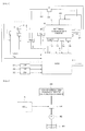
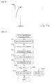
- FIG. 1 is a schematic diagram showing a configuration of an internal combustion engine and a control system therefor according to one embodiment of the present invention.
- FIG. 2 is a schematic diagram showing a configuration of a valve operating characteristic varying device.
- an internal combustion engine (hereinafter referred to as "engine") 1 having, for example, four cylinders is provided with intake valves, exhaust valves, and cams for driving the intake valves and the exhaust valves.
- the engine 1 is provided with a valve operating characteristic varying device 40 having a valve operating characteristic varying mechanism 42 as a cam phase varying mechanism for continuously varying the operating phase of the cams for driving the intake valves with reference to a rotational angle of the crank shaft of the engine 1.
- the valve operating characteristic varying mechanism 42 varies the operating phase of the cam for driving each intake valve, and consequently varies the operating phase of each intake valve.
- the engine 1 has an intake pipe 2 provided with a throttle valve 3.
- a throttle valve opening sensor 4 for detecting an opening of the throttle valve 3 is connected to the throttle valve 3.
- the detection signal of the throttle valve opening sensor 4 is supplied to an electronic control unit (referred to as "ECU") 5.
- An actuator 7 for actuating the throttle valve 3 is connected to the throttle valve 3, and the operation of the actuator 7 is controlled by the ECU 5.
- An exhaust gas recirculation passage 22 is disposed between an exhaust pipe 21 and the intake pipe 2, and connected to the intake pipe 2 downstream of the throttle valve 3.
- the exhaust gas recirculation passage 22 is provided with an exhaust gas recirculation control valve 23 for controlling a recirculation amount of exhaust gases. Operation of the exhaust gas recirculation control valve 23 is controlled by the ECU 5.
- An intake air flow rate sensor 13 for detecting an intake air flow rate GAIR of the engine 1 is disposed in the intake pipe 2.
- the detection signal of the intake air flow rate sensor 13 is supplied to the ECU 5.
- Fuel injection valves 6 are inserted into the intake pipe 2 at locations intermediate between the cylinder block of the engine 1 and the throttle valve 3 and slightly upstream of the respective intake valves (not shown). These fuel injection valves 6 are connected to a fuel pump (not shown), and electrically connected to the ECU 5. A valve opening period of each fuel injection valve 6 is controlled by a signal output from the ECU 5.
- a spark plug 15 of each cylinder of the engine 1 is connected to the ECU 5.
- the ECU 5 supplies an ignition signal to each spark plug 15 and controls the ignition timing.
- An intake pressure sensor 8 for detecting an intake pressure PBA and an intake air temperature sensor 9 for detecting an intake air temperature TA are disposed downstream of the throttle valve 3.
- an engine coolant temperature sensor 10 for detecting an engine coolant temperature TW is mounted on the body of the engine 1. The detection signals from these sensors are supplied to the ECU 5.
- a crank angle position sensor 11 and a cam angle position sensor 12 are connected to the ECU 5.
- the crank angle position sensor 11 is provided to detect a rotational angle of a crankshaft (not shown) of the engine 1
- the cam angle position sensor 12 is provided to detect a rotational angle of the camshaft to which the cams for driving the intake valves of the engine 1 are fixed.
- a signal corresponding to the rotational angle detected by the crank angle position sensor 11 and a signal corresponding to the rotational angle detected by the cam angle position sensor 12 are supplied to the ECU 5.
- the crank angle position sensor 11 generates one pulse (hereinafter referred to as "CRK pulse”) at every constant crank angle period (e.g., a period of 30 degrees) and a pulse for specifying a predetermined angle position of the crankshaft.
- the cam angle position sensor 12 generates a pulse at a predetermined crank angle position for a specific cylinder of the engine 1 (this pulse will be hereinafter referred to as “CYL pulse”).
- the cam angle position sensor 12 further generates a pulse at a top dead center (TDC) starting the intake stroke in each cylinder (this pulse will be hereinafter referred to as "TDC pulse”).
- TDC top dead center
- An actual operating phase CAIN of the camshaft is detected based on the correlation between the TDC pulse output from the cam angle position sensor 12 and the CRK pulse output from the crank angle position sensor 11.
- a knock sensor 14 for detecting a high frequency vibration is mounted on a proper position of the engine 1.
- the detection signal of the knock sensor 14 is supplied to the ECU 5.
- an accelerator sensor 31, a vehicle speed sensor 32, and an atmospheric pressure sensor 33 are also connected to the ECU 5.
- the accelerator sensor 31 detects a depression amount AP of an accelerator pedal of the vehicle driven by the engine 1 (the depression amount will be hereinafter referred to as "accelerator operation amount").
- the vehicle speed sensor 32 detects a running speed (vehicle speed) VP of the vehicle.
- the atmospheric pressure sensor 33 detects an atmospheric pressure PA. The detection signals from these sensors are supplied to the ECU 5.
- the valve operating characteristic varying device 40 includes a valve operating characteristic varying mechanism 42 and a solenoid valve 44.
- the valve operating characteristic varying mechanism 42 continuously varies an operating phase of each intake valve.
- An opening of the solenoid valve 44 is continuously varied to change the operating phase of each intake valve.
- the operating phase CAIN of the camshaft is used as a parameter indicative of the operating phase of the intake valve (hereinafter referred to as "intake valve operating phase CAIN").
- a lubricating oil in an oil pan 46 is pressurized by an oil pump 45, and supplied to the solenoid valve 44. It is to be noted that a specific configuration of the valve operating characteristic varying mechanism 42 is described, for example, in Japanese Patent Laid-open No. 2000-227013 .
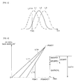
- the intake valve is driven with a phase from the most advanced phase shown by the broken line L1 in FIG. 3 to the most retarded phase shown by the dot-and-dash line L3, depending on a change in the operating phase CAIN of the camshaft.
- the characteristic shown by the solid line L2 is the center of the variable phase range.
- the intake valve operating phase CAIN is defined as an advancing angular amount from the most retarded phase.
- the ECU 5 includes an input circuit having various functions including a function of shaping the waveforms of input signals from the various sensors, a function of correcting the voltage levels of the input signals to a predetermined level, and a function of converting analog signal values into digital signal values.
- the ECU5 further includes a central processing unit (hereinafter referred to as "CPU"), a memory circuit, and an output circuit.
- the memory circuit preliminarily stores various operating programs to be executed by the CPU and the results of computation or the like by the CPU.
- the output circuit supplies drive signals to the actuator 7, the fuel injection valves 6, the ignition plugs 15, the exhaust gas recirculation control valve 23, and the solenoid valve 44.
- the CPU in the ECU 5 performs the ignition timing control, the opening control of the throttle valve 3, the control of an amount of fuel to be supplied to the engine 1 (the opening period of each fuel injection valve 6), the exhaust gas recirculation amount control with the exhaust gas recirculation control valve 23, and the valve operating characteristic control with the solenoid valve 44, according to the detection signals from the above-described sensors.
- FIG. 4 is a graph for illustrating a calculation method of a total exhaust gas recirculation ratio (hereinafter referred to as "total EGR ratio") REGRT in this embodiment.
- FIG. 4 shows a relationship between the intake pressure PBA and an amount of gases supplied to the engine (an amount of air + an amount of recirculated exhaust gases). The relationship of FIG. 4 is obtained under the condition that the engine rotational speed NE and the intake valve operating phase CAIN are constant.
- the total EGR ratio REGRT is a ratio of the total exhaust gas recirculation amount with respect to the total intake gas amount (theoretical intake air amount GATH) (refer to the equation (2) described later).
- the total exhaust gas recirculation amount is a sum of the internal exhaust gas recirculation amount and the external exhaust gas recirculation amount through the exhaust gas recirculation passage 22.
- the operating point PWOT corresponds to yhr state where the throttle valve 3 is fully opened, and indicates the theoretical operating point at which no external exhaust gas recirculation is performed, and no internal exhaust gas recirculation is performed.
- the intake air amount takes the maximum value under the condition that the engine rotational speed NE is constant.
- the residual gas ratio (the internal exhaust gas recirculation ratio) does not actually become "0" in the state where the throttle valve 3 is fully opened.
- the internal exhaust gas recirculation ratio takes the minimum value, since the intake pressure PBAWOT becomes almost equal to the atmospheric pressure PA.
- the straight line LTH passing the operating point PWOT and the starting point indicates a theoretical relationship between the intake air amount and the intake pressure, wherein no external exhaust gas recirculation and no internal exhaust gas recirculation is performed.
- This straight line LTH is hereinafter referred to as "theoretical intake air amount straight line LTH".
- the line L11 indicates a relationship corresponding to the state where only the internal exhaust gas recirculation is performed
- the line L12 indicates a relationship corresponding to the state where both of the internal exhaust gas recirculation and the external exhaust gas recirculation are performed. It is to be noted that the lines L11 and L12 are indicated as straight lines for explanation, although they are not actually straight lines.
- the theoretical intake air amount GATH is expressed with the following equation (1).
- GAIRCYL indicates an intake air amount (fresh air amount)
- GEGRIN, GEGREX, and GEGRT respectively indicate an internal exhaust gas recirculation amount, an external exhaust gas recirculation amount, and a total exhaust gas recirculation amount.
- FIG. 5 is a graph for illustrating a case where the atmospheric pressure changes.
- the wide-open operating point PWOT1 is an operating point corresponding to a reference state in which the intake pressure PBA is equal to a reference intake pressure PBASTD (for example, 100 kPa (750 mmHg)).
- PBASTD reference intake pressure
- the operating point PWOT1 moves to the operating point PWOT2 and next to the operating point PWOT3 on the theoretical intake air amount straight line LTH.
- the curves L21 - L23 starting from the operating points PWOT1 - PWOT3 respectively indicate the intake air amount GAIRCYL which is obtained by taking the internal exhaust gas recirculation into account (i.e., when no external exhaust gas recirculation is performed).
- TASTD is an intake air temperature in a reference condition (for example, 25 degrees C)
- GAWOTSTD is an intake air amount corresponding to the wide-open operating point PWOT in the reference condition.
- GAWOTSTD is hereinafter referred to as "reference theoretical wide-open air amount GAWOTSTD”.
- GAWOT is an intake air amount corresponding to the wide-open operating point PWOT in the operating condition of the detected intake air temperature TA.
- GAWOT is hereinafter referred to as "theoretical wide-open air amount GAWOT”.
- n in the equation (3) is a constant which is empirically set to a value from “0" to "1", for example, set to "0.5".
- GAWOT GAWOTSTD ⁇ TASTD + 273 TA + 273 n
- the straight line LTHSTD shown in FIG. 6 is a theoretical intake air amount straight line in the reference condition
- the straight line LTH is a theoretical intake air amount straight line corresponding to the detected intake air temperature TA. It is to be noted that FIG. 6 corresponds to an example in which the detected intake air temperature TA is higher than the reference intake air temperature TASTD.
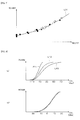
- FIG. 7 is a graph for illustrating a relationship between the total EGR ratio REGRT and an optimum ignition timing IGMBT (the engine rotational speed NE is fixed).
- the optimum ignition timing IGMBT is an ignition timing at which the engine output torque becomes the maximum.
- the black circles ( ⁇ ) and the white circles (O) correspond to an operating condition where the intake valve operating phase CAIN is "0" ⁇ degree
- the black squares ( ⁇ ) and the white squares ( ⁇ ) correspond to an operating condition where the intake valve operating phase CAIN is "20" degrees
- the black triangles ( ⁇ ) and the white triangles ( ⁇ ) correspond to an operating condition where the intake valve operating phase CAIN is "45" degrees.
- the black symbols ( ⁇ , ⁇ , and ⁇ ) correspond to the case where no external exhaust gas recirculation is performed (only the internal exhaust gas recirculation is performed), and the white symbols (O, ⁇ , and ⁇ ) correspond to the case where the external exhaust gas recirculation is performed (both of the internal exhaust gas recirculation and the external exhaust gas recirculation are performed).
- the relationship between the total EGR ratio REGRT and the optimum ignition timing IGMBT depends neither on the operating phase CAIN of the intake valve nor on whether the external exhaust gas recirculation is performed or not, i.e., the curve L31 can represent the relationship between REGRT and IGMBT. Accordingly, only one optimum ignition timing calculation map (IGMBT map) set according to the engine rotational speed NE and the total EGR ratio REGRT, makes it possible to set the optimum ignition timing corresponding to all engine operating conditions. Consequently, the manpower for setting maps can greatly be reduced.
- IGMBT map optimum ignition timing calculation map
- FIG. 8 shows changes in the mass combustion rate RCMB of the air-fuel mixture sucked in the combustion chamber (the horizontal axis indicates the crank angle CA).
- FIG. 8(a) shows changes in the mass combustion rate RCMB in a condition where the charging efficiency ⁇ c is constant and the total EGR ratio REGRT is changed.
- the curves L41 - L43 correspond respectively to operating conditions in which the total EGR ratio REGRT is set to "6.3 %", "16.2 %, and "26.3 %".
- the curve L41 indicates the fastest burning speed. That is, it is confirmed that the total EGR ratio REGRT is a main factor which changes the burning speed of the air-fuel mixture.
- FIG. 8(b) shows changes in the mass combustion rate RCMB in a condition where the total EGR ratio REGRT is constant and the charging efficiency ⁇ c is changed (the solid line, the dashed line, and the dot-and-dash line).
- the three lines indicated in FIG. 8(b) almost overlap with each other, which shows that the burning speed of the air-fuel mixture hardly changes even if the charging efficiency ⁇ c is changed. Therefore, it is preferable that the optimum ignition timing IGMBT is set not according to the charging efficiency ⁇ c (the fresh intake air amount) but according to the total EGR ratio REGRT.
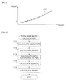
- FIG. 9 shows a relationship between the total EGR ratio REGRT and an EGR knock correction amount DEGRT of the ignition timing (the engine rotational speed NE is fixed).
- the EGR knock correction amount DEGRT is an ignition timing correction amount (a correction amount in the advancing direction) applied to a calculation of a knock limit ignition timing IGKNOCK, in order to perform the correction corresponding to changes in the exhaust gas recirculation amount.
- the knock limit ignition timing IGKNOCK corresponds to an occurrence limit of knocking in the engine, i.e., the most advanced ignition timing at which no knocking occurs.
- the curve L51 can represent the relationship between the total EGR ratio REGRT and the EGR knock correction amount DEGRT under the condition that the engine rotational speed NE is fixed. Therefore, the EGR knock correction amount DEGRT can appropriately be set by using the DEGRT map which is set according to the engine rotational speed NE and the total EGR ratio REGRT. It is to be noted that a modification according to the intake valve operating phase CAIN may be necessary due to differences in the engine characteristics, although the relationship indicated with the curve L51 is basically independent of the intake valve operating phase CAIN. In such case, two or more tables corresponding to different intake valve operating phases CAIN may be used, or the correction according to the intake valve operating phase CAIN may be performed.
- FIG. 10 is a flowchart of a process for calculating the total EGR ratio REGRT. This process is executed by the CPU in the ECU 5 in synchronism with generation of the TDC pulse.
- step S11 a GAWOTSTD map which is set according to the engine rotational speed NE and the intake valve operating phase CAIN, is retrieved to calculate the reference theoretical wide-open air amount GAWOTSTD.
- step S12 the correction according to the intake air temperature TA with the above-described equation (3) is performed to calculate the theoretical wide-open air amount GAWOT.
- step S 13 the detected intake pressure PBA is applied to the following equation (4) to calculate the theoretical intake air amount GATH.
- GATH GAWOT ⁇ PBA / PBASTD
- step S14 the detected intake air flow rate GAIR [g/sec] is applied to the following equation (5) to perform the conversion to the the intake air amount GAIRCYL in one intake stroke of one cylinder.
- KC in the equation (5) is a conversion coefficient.
- GAIRCYL GAIR ⁇ KC / NE
- step S15 the total EGR ratio REGRT is calculated by the above-described equation (2).
- FIG. 11 is a flowchart of a process for calculating the ignition timing IGLOG indicated by an advance angular amount from the compression top dead center. This process is executed by the CPU in the ECU 5 in synchronism with generation of the TDC pulse.
- step S21 an IGMBT map (refer to FIG. 7 ) is retrieve according to the engine rotational speed NE and the total EGR ratio REGRT to calculate the optimum ignition timing IGMBT.
- step S22 the IGKNOCK calculation process shown in FIG. 12 is executed to calculate the knock limit ignition timing IGKNOCK.
- step S23 it is determined whether or not the optimum ignition timing IGMBT is equal to or greater than the knock limit ignition timing IGKNOCK. If the answer to step S23 is affirmative (YES), a basic ignition timing IGB is set to the knock limit ignition timing IGKNOCK (step S24). If the optimum ignition timing IGMBT is less than the knock limit ignition timing IGKNOCK, the basic ignition timing IGB is set to the optimum ignition timing IGMBT (step S25).
- step S26 the ignition timing IGLOG is calculated by adding the basic ignition timing IGB and a correction value IGCR which is for example calculated according to the engine coolant temperature TW.
- the CPU in the ECU 5 performs the ignition with the ignition plug 15 in accordance with the calculated ignition timing IGLOG.
- FIG. 12 is a flowchart of the IGKNOCK calculation process executed in step S22 of FIG. 11 .
- step S31 an IGKNOCKB map is retrieved according to the engine rotational speed NE and the intake air amount GAIRCYL to calculate a basic knock limit ignition timing IGKNOCKB.
- the IGKNOCKB map is set corresponding to the state where the total EGR ratio REGRT is set to a predetermined reference value and the intake valve operating phase CAIN is set to "0 degree".
- step S32 a CMPR table shown in FIG. 13(a) is retrieved according to the intake valve operating phase CAIN to calculate the effective compression ratio CMPR.
- the intake valve closing timing CACL changes depending on the intake valve operating phase CAIN, which accordingly changes the effective compression ratio CMPR.
- the relationship between the intake valve operating phase CAIN and the effective compression ratio CMPR which is previously calculated, is set in the CMPR table.
- step S33 a DCMPR map is retrieved according to the effective compression ratio CMPR and the engine rotational speed NE to calculate a compression ratio knock correction amount DCMPR.
- the compression ratio knock correction amount DCMPR takes a value which is equal to or less than "0", and is set so as to decrease as the effective compression ratio CMPR increases, as shown in FIG. 13(b) .
- step S34 a DEGRT map is retrieved according to the total EGR ratio REGRT and the engine rotational speed NE to calculate the EGR knock correction amount DEGRT.
- the EGR knock correction amount DEGRT takes a value which is greater than "0", and is set so as to increase as the total EGR ratio REGRT increases, as shown in FIG. 9 .
- step S35 the basic knock limit ignition timing IGKNOCKB, the compression ratio knock correction amount DCMPR, and the EGR knock correction amount DEGRT are applied to the following equation (6) to calculate the knock limit ignition timing IGKNOCK.
- IGKNOCK IGKNOCKB + DCMPR + DEGRT
- the valve opening time period of the fuel injection valve 6, i.e., the fuel injection amount TOUT, is also calculated using the total EGR ratio REGRT.
- the knock limit ignition timing IGKNOCK is modified according to the detection result of knocking by the knock sensor 14. This modification process is omitted in FIG. 12 .
- FIG. 14 shows graphs for explaining the method of calculating the effective compression ratio CMPR.
- FIG. 14(a) shows a lift curve of the intake valve
- FIG. 14(b) shows the A section in FIG. 14(a) , i.e., an expanded view of the lift curve in the vicinity of the valve closing timing.
- Crank angles CA1, CA2, and CA3 at which the lift amount LFT is equal to a predetermined lift amount threshold value LFTCMP (which is set to a lift amount a little greater than "0") are calculated corresponding to the lift curves L61, L62, and L63 of FIGs.
- CMPR1, CMPR2, and CMPR3 VCC1, VCC2, and VCC3 which correspond respectively to the piston positions corresponding to the crank angles CA1, CA2, and CA3 as shown in FIG. 14(c) .
- the effective compression ratios CMPR1, CMPR2, and CMPR3 corresponding to the lift curves L61 - L63 are calculated by the following equations (7) - (9).
- VCCTDC in these equations is a cylinder volume when the piston is positioned at the top dead center.
- CMPR ⁇ 1 VCC ⁇ 1 / VCCTDC
- CMPR ⁇ 2 VCC ⁇ 2 / VCCTDC
- CMPR ⁇ 3 VCC ⁇ 3 / VCCTDC
- the theoretical wide-open intake air amount GAWOT which is an intake air amount corresponding to the state where the throttle valve 3 is fully opened
- the theoretical intake air amount GATH which is an intake air amount corresponding to the state where the exhaust gas recirculation amount is equal to "0”
- the total exhaust gas recirculation ratio REGRT is calculated using the detected intake air amount GAIRCYL and the theoretical intake air amount GATH. Accordingly, it is not necessary for calculating the exhaust gas recirculation ratio to previously set many maps corresponding to various engine operating conditions, which can greatly reduce the man power for setting the maps. Further, even if the atmospheric pressure changes, the correcting calculation for the change in the atmospheric pressure is not necessary, which makes it possible to calculate the exhaust gas recirculation ratio simply and accurately.
- the optimum ignition timing IGMBT is calculated according to the total exhaust gas recirculation ratio REGRT. Accordingly, in addition to the external exhaust gas recirculation, the internal exhaust gas recirculation is also taken into account, thereby obtaining the optimum ignition timing IGMBT with high accuracy. It is confirmed that the relationship between the total exhaust gas recirculation ratio REGRT and the optimum ignition timing IGMBT is not affected by the intake valve operating phase CAIN or whether the external exhaust gas recirculation is performed or not (refer to FIG. 7 ). Accordingly, by setting the optimum ignition timing IGMBT according to the total exhaust gas recirculation ratio REGRT, the optimum ignition timing IGMBT suitable for the engine operating condition can easily be calculated. Further, by performing the ignition timing control using the calculated optimum ignition timing IGMBT, the output performance of the engine can sufficiently be effected.
- the EGR knocking correction amount DEGRT is calculated according to the total EGR ratio REGRT
- the knock limit ignition timing IGKNOCK is calculated by correcting the basic knock limit ignition timing IGKNOCKB with the EGR knocking correction amount DEGRT.
- the knock limit ignition timing IGKNOCK is highly correlated with the total EGR ratio REGRT (refer to FIG. 9 ). Therefore, performing the correction with the EGR knocking correction amount DEGRT calculated according to the total EGR ratio REGRT makes it possible to perform the ignition timing control with high accuracy, wherein the engine output is maximized within the range for surely avoiding the knocking.
- the compression ratio correction amount DCMPR is calculated according to the intake valve operating phase CAIN, and the basic knock limit ignition timing IGKNOCKB is corrected with the compression ratio correction amount DCMPR. Therefore, an accurate value of the knock limit ignition timing IGKNOCK can be obtained when changing the intake valve operating phase CAIN according to the engine operating condition.
- the effective compression ratio CMPR is calculated according to the intake valve operating phase CAIN, and the compression ratio correction amount DCMPR is calculated according to the effective compression ratio CMPR.
- the knock limit ignition timing IGKNOCK changes depending on the effective compression ratio CMPR. Therefore, the correction of the knock limit ignition timing IGKNOCK can appropriately be performed by calculating the effective compression ratio CMPR according to the intake valve operating phase CAIN, and correcting the basic knock limit ignition timing IGKNOCKB according to the effective compression ratio CMPR.
- the crank angle position sensor 11 and the intake pressure sensor 8 correspond respectively to the rotational speed detecting means and the intake pressure detecting means
- the valve operating characteristic varying mechanism 42 corresponds to the intake valve operating phase varying mechanism
- the intake air flow rate sensor 13 corresponds to the intake air amount obtaining means.
- the ECU 5 constitutes the wide-open intake air amount calculating means, the theoretical intake air amount calculating means, the exhaust gas recirculation ratio calculating means, the optimum ignition timing calculating means, the knock limit ignition timing calculating means, and the correcting means. Specifically steps S11 and S12 of FIG.
- step S10 corresponds to the wide-open intake air amount calculating means
- step S13 corresponds to the theoretical intake air amount calculating means
- step S15 corresponds to the exhaust gas recirculation ratio calculating means
- step S21 of FIG. 11 corresponds to the optimum ignition timing calculating means
- the process of FIG. 12 corresponds to the knock limit ignition timing calculating means
- steps S32, S33, and S35 correspond to the correcting means.
- the total EGR ratio REGRT calculated in the process shown in FIG. 10 accurately coincides with the actual total exhaust gas recirculation ratio, when the changing speed of the throttle valve opening TH is comparatively low.
- rapid acceleration operating condition the transient operating condition where the increasing speed of the throttle valve opening TH is high
- FIG. 15 shows time charts for illustrating this problem.
- the increase in the intake pressure PBA delays from the increase in the throttle valve opening TH , and the increase in the actual intake air amount GAIRACT further delays from the increase in the intake pressure PBA. Therefore, the total EGR ratio REGRT calculated using the intake pressure PBA and the detected intake air flow rate GAIR increases to about 60% ( FIG. 15 (d) ) although the actual total EGR ratio in the rapid acceleration operating condition decreases from the value before the acceleration starts. Consequently, the ignition timing IGLOG calculated using the total EGR ratio REGRT is greatly advanced from the desired value, which causes a knocking.
- the total EGR ratio REGRT is set to "0" when the throttle valve opening TH is equal to or greater than the effective throttle valve opening THEFCT.
- the effective throttle valve opening THEFCT is a throttle valve opening at which the intake pressure PBA hardly increases in response to the increase in the throttle valve opening TH, i.e., the throttle valve opening at which the increasing rate (dPBA/dTH) of the intake pressure PBA with respect to the increase in the throttle valve opening TH becomes equal to or less than a predetermined increasing rate under the condition where the engine rotational speed is fixed.
- FIG. 16 shows the relationship between the throttle valve opening TH and the intake pressure PBA when the engine rotational speed is 700 rpm. THEFCT and THFO in FIG.
- the effective throttle valve opening THEFCT takes a comparatively small value (for example, about 15% - 20% of the fully-opened opening THFO).
- the total EGR ratio REGRT is set to "0" in the vicinity of time t1 of FIG. 15 . Accordingly, the above-described problem can be solved.
- FIG. 17 is a flowchart of the total EGR ratio calculation process in this embodiment. This process is obtained by adding steps S21 - S23 to the process of FIG. 10 .
- step S21 a THEFCT table shown in FIG. 18 is retrieved according to the engine rotational speed NE to calculate the effective throttle valve opening THEFCT.
- the THEFCT table is set so that the effective throttle valve opening THEFCT increases as the engine rotational speed NE increases.
- step S22 it is determined whether or not the throttle valve opening TH is equal to or greater than the effective throttle valve opening THEFCT. If the answer to step S22 is affirmative (YES), the engine 1 is determined to be in the rapid acceleration operating condition, and the total EGR ratio REGRT is set to "0" (step S23). If the answer to step S22 is negative (NO), i.e., the throttle valve opening TH is less than the effective throttle valve opening THEFCT, the process proceeds to step S15 to calculate the total EGR ratio REGRT using the equation (2).
- the effective throttle valve opening THEFCT is calculated according to the engine rotational speed NE, and the total EGR ratio REGRT is set to "0" when the throttle valve opening TH is equal to or greater than the effective opening THEFCT.
- the increase in the amount of air actually supplied to the cylinder delays from the increase in the intake pressure PBA (refer to FIG. 15 ). Therefore, if calculating the total EGR ratio using the actual intake air amount GAIRCYL and the theoretical intake air amount GATH which is calculated according to the intake pressure PBA, the calculation error becomes large.
- the actual exhaust gas recirculation ratio substantially becomes "0". Accordingly, the actual exhaust gas recirculation ratio can be approximated more accurately by setting the total EGR ratio REGRT to "0". Consequently, performing the ignition timing control and the fuel supply amount control using the total EGR ratio REGRT makes it possible to prevent unsuitable control during the transient operating condition of rapid acceleration, thereby preventing occurrence of knocking or deterioration of the exhaust gas characteristic.
- the throttle valve opening sensor 4 corresponds to the throttle valve opening detecting means
- step S21 of FIG. 17 corresponds to the effective opening calculating means
- steps S 15, S22, and S23 correspond to the exhaust gas recirculation ratio calculating means.
- the total EGR ratio REGRT is calculated using the intake air flow rate GAIR detected by the intake air flow rate sensor 13 in the above-described embodiments.
- an estimated intake air flow rate HGAIR may be calculated according to the throttle valve opening TH, the atmospheric pressure PA, and the intake pressure PBA, and the total EGR ratio REGRT may be calculated using the estimated intake air flow rate HGAIR.
- the present invention is applied to controlling the internal combustion engine wherein the external exhaust gas recirculation through the exhaust gas recirculation passage 22 is performed.
- the present invention is applicable also to controlling the internal combustion engine wherein no external exhaust gas recirculation is performed (only the internal exhaust gas recirculation is performed).
- the effective compression ratio CMPR is calculated according to the intake valve operating phase CAIN
- the compression ratio knock correction amount DCMPR is calculated according to the effective compression ratio CMPR.
- the compression ratio knock correction amount DCMPR may directly be calculated according to the intake valve operating phase CAIN.
- the present invention can also be applied to controlling a watercraft propulsion engine such as an outboard engine having a vertically extending crankshaft. Description of reference numerals
Landscapes
- Engineering & Computer Science (AREA)
- Chemical & Material Sciences (AREA)
- Combustion & Propulsion (AREA)
- Mechanical Engineering (AREA)
- General Engineering & Computer Science (AREA)
- Combined Controls Of Internal Combustion Engines (AREA)
- Electrical Control Of Ignition Timing (AREA)
- Output Control And Ontrol Of Special Type Engine (AREA)
- Exhaust-Gas Circulating Devices (AREA)
- Electrical Control Of Air Or Fuel Supplied To Internal-Combustion Engine (AREA)
Applications Claiming Priority (2)
| Application Number | Priority Date | Filing Date | Title |
|---|---|---|---|
| JP2009287500 | 2009-12-18 | ||
| PCT/JP2010/066476 WO2011074302A1 (ja) | 2009-12-18 | 2010-09-24 | 内燃機関の制御装置 |
Publications (2)
| Publication Number | Publication Date |
|---|---|
| EP2514952A1 true EP2514952A1 (de) | 2012-10-24 |
| EP2514952A4 EP2514952A4 (de) | 2014-02-19 |
Family
ID=44167068
Family Applications (1)
| Application Number | Title | Priority Date | Filing Date |
|---|---|---|---|
| EP10837332.5A Withdrawn EP2514952A4 (de) | 2009-12-18 | 2010-09-24 | Steuerungsvorrichtung für einen verbrennungsmotor |
Country Status (5)
| Country | Link |
|---|---|
| US (1) | US20120290195A1 (de) |
| EP (1) | EP2514952A4 (de) |
| JP (2) | JP5270008B2 (de) |
| CN (1) | CN102597466B (de) |
| WO (1) | WO2011074302A1 (de) |
Cited By (1)
| Publication number | Priority date | Publication date | Assignee | Title |
|---|---|---|---|---|
| IT201900004879A1 (it) * | 2019-04-01 | 2020-10-01 | Magneti Marelli Spa | Metodo per il controllo della combustione di un motore a combustione interna |
Families Citing this family (13)
| Publication number | Priority date | Publication date | Assignee | Title |
|---|---|---|---|---|
| EP2327868B1 (de) * | 2008-09-26 | 2015-04-08 | Honda Motor Co., Ltd. | Frequenzkomponentenanalysegerät |
| JP5043165B2 (ja) * | 2010-08-27 | 2012-10-10 | 本田技研工業株式会社 | 内燃機関の制御装置 |
| US9291143B2 (en) * | 2011-10-24 | 2016-03-22 | Nissan Motor Co., Ltd. | Spark ignition internal combustion engine and control method of spark ignition internal combustion engine |
| JP5547858B2 (ja) * | 2012-01-19 | 2014-07-16 | 本田技研工業株式会社 | 内燃機関の制御装置 |
| JP2014111927A (ja) * | 2012-10-31 | 2014-06-19 | Ngk Spark Plug Co Ltd | 点火時期制御装置及び点火システム |
| JP6092070B2 (ja) * | 2013-10-09 | 2017-03-08 | ヤンマー株式会社 | エンジン |
| WO2016017214A1 (ja) | 2014-08-01 | 2016-02-04 | 本田技研工業株式会社 | 内燃機関の制御装置及び制御方法 |
| US9556810B2 (en) * | 2014-12-31 | 2017-01-31 | General Electric Company | System and method for regulating exhaust gas recirculation in an engine |
| US9938953B2 (en) * | 2015-06-17 | 2018-04-10 | Ford Global Technologies, Llc | Method and system for engine control |
| JP6446081B2 (ja) * | 2017-03-13 | 2018-12-26 | 本田技研工業株式会社 | 内燃機関の制御装置 |
| JP6899416B2 (ja) * | 2019-09-24 | 2021-07-07 | 本田技研工業株式会社 | 内燃機関の制御装置 |
| JP2023020229A (ja) * | 2021-07-30 | 2023-02-09 | マツダ株式会社 | エンジンシステム |
| JP2023020228A (ja) * | 2021-07-30 | 2023-02-09 | マツダ株式会社 | エンジンシステム |
Citations (5)
| Publication number | Priority date | Publication date | Assignee | Title |
|---|---|---|---|---|
| EP0893590A2 (de) * | 1997-07-23 | 1999-01-27 | Mazda Motor Corporation | Saugluftsteuerungssystem für eine Brennkraftmaschine mit Abgasrückführungsvorrichtung |
| US6367462B1 (en) * | 2000-09-13 | 2002-04-09 | Delphi Technologies, Inc. | Engine torque management method with high dilution EGR control |
| US20040236493A1 (en) * | 2002-09-19 | 2004-11-25 | Sisken Kevin Dean | Method for controlling an engine with an egr system |
| JP2006200460A (ja) * | 2005-01-21 | 2006-08-03 | Honda Motor Co Ltd | 内燃機関の制御装置 |
| JP2008261256A (ja) * | 2007-04-11 | 2008-10-30 | Toyota Motor Corp | 内燃機関のegrシステム |
Family Cites Families (39)
| Publication number | Priority date | Publication date | Assignee | Title |
|---|---|---|---|---|
| JPS62170752A (ja) * | 1986-01-22 | 1987-07-27 | Mitsubishi Electric Corp | 内燃機関の燃料噴射制御装置 |
| US5029569A (en) * | 1990-09-12 | 1991-07-09 | Ford Motor Company | Method and apparatus for controlling an internal combustion engine |
| JP2905822B2 (ja) * | 1990-10-31 | 1999-06-14 | スズキ株式会社 | エンジンの点火時期制御装置 |
| JPH0828364A (ja) * | 1994-07-20 | 1996-01-30 | Mitsubishi Electric Corp | 排気ガス還流制御装置の故障検出装置 |
| JP3331789B2 (ja) * | 1994-11-29 | 2002-10-07 | トヨタ自動車株式会社 | 内燃機関の点火時期制御装置 |
| US5515833A (en) * | 1994-12-19 | 1996-05-14 | Ford Motor Company | Exhaust gas recirculation system with improved altitude compensation |
| JPH0960543A (ja) * | 1995-08-24 | 1997-03-04 | Hitachi Ltd | エンジン制御装置 |
| JP3050794B2 (ja) * | 1996-03-01 | 2000-06-12 | 富士重工業株式会社 | エンジンの制御装置 |
| JP3521632B2 (ja) * | 1996-07-30 | 2004-04-19 | 日産自動車株式会社 | 内燃機関の制御装置 |
| JPH10103121A (ja) * | 1996-09-25 | 1998-04-21 | Fuji Heavy Ind Ltd | エンジンの制御装置 |
| US6098602A (en) * | 1999-01-15 | 2000-08-08 | Ford Global Technologies, Inc. | Exhaust gas recirculation system |
| JP3447601B2 (ja) | 1999-02-05 | 2003-09-16 | 本田技研工業株式会社 | 内燃機関の動弁制御装置 |
| JP4243416B2 (ja) * | 2000-06-07 | 2009-03-25 | 本田技研工業株式会社 | 内燃機関の燃料供給制御装置 |
| US6851409B2 (en) * | 2001-10-12 | 2005-02-08 | Hitachi Unisia Automotive, Ltd. | Apparatus and method for controlling intake air amount of internal combustion engine |
| JP2003138975A (ja) * | 2001-11-02 | 2003-05-14 | Hitachi Unisia Automotive Ltd | 内燃機関の吸入空気流量計測装置 |
| JP2003239787A (ja) * | 2002-02-15 | 2003-08-27 | Honda Motor Co Ltd | 内燃機関の制御装置 |
| JP2003269306A (ja) | 2002-03-13 | 2003-09-25 | Nissan Motor Co Ltd | エンジンの点火時期制御装置 |
| JP4069361B2 (ja) * | 2002-06-11 | 2008-04-02 | 三菱自動車工業株式会社 | 内燃機関の点火時期制御装置 |
| JP3904076B2 (ja) * | 2002-08-12 | 2007-04-11 | トヨタ自動車株式会社 | 内燃機関のegr制御装置 |
| US6845753B2 (en) * | 2002-10-29 | 2005-01-25 | Ford Global Technologies, Llc | System and method for controlling ignition timing in an engine |
| JP4443839B2 (ja) * | 2003-02-12 | 2010-03-31 | 本田技研工業株式会社 | 内燃機関の制御装置 |
| JP2004251183A (ja) * | 2003-02-19 | 2004-09-09 | Toyota Motor Corp | 内燃機関の制御装置 |
| JP4277535B2 (ja) * | 2003-02-19 | 2009-06-10 | トヨタ自動車株式会社 | 内燃機関の内部egr量推定装置 |
| JP4357284B2 (ja) * | 2003-05-15 | 2009-11-04 | トヨタ自動車株式会社 | 内燃機関の制御装置 |
| EP1607606B1 (de) * | 2004-06-15 | 2008-04-09 | C.R.F. Società Consortile per Azioni | Verfahren und Einrichtung zur Bestimmung der Ansaugluftmenge einer Brennkraftmaschine basierend auf der Messung der Sauerstoff-Konzentration in einem der Brennkraftmaschine zugeführten Gasgemisch |
| EP1617056B1 (de) * | 2004-07-14 | 2014-10-22 | Honda Motor Co., Ltd. | System zur Steuerung einer Brennkraftmaschine |
| JP4376799B2 (ja) * | 2005-01-19 | 2009-12-02 | 株式会社日立製作所 | 内燃機関の点火時期制御装置 |
| JP2006322363A (ja) * | 2005-05-18 | 2006-11-30 | Mazda Motor Corp | エンジンの内部egr率推定方法 |
| JP2007032364A (ja) * | 2005-07-25 | 2007-02-08 | Toyota Motor Corp | 吸気系異常検知装置 |
| EP2292915B1 (de) * | 2005-12-20 | 2013-07-24 | BorgWarner, Inc. | Steuerung zur Abgasrückführung in turboaufgeladenen Brennkraftmaschinen |
| JP4857915B2 (ja) * | 2006-06-02 | 2012-01-18 | マツダ株式会社 | ディーゼルエンジンの制御装置 |
| JP4823948B2 (ja) * | 2007-03-23 | 2011-11-24 | 富士重工業株式会社 | エンジンの制御装置 |
| US7536249B2 (en) * | 2007-07-12 | 2009-05-19 | Delphi Technologies, Inc. | System and method for a pumping torque estimation model for all air induction configurations |
| JP4821730B2 (ja) * | 2007-07-27 | 2011-11-24 | トヨタ自動車株式会社 | 内燃機関の点火時期制御装置 |
| JP2009068388A (ja) * | 2007-09-12 | 2009-04-02 | Honda Motor Co Ltd | 内燃機関の制御装置 |
| JP2009275676A (ja) * | 2008-05-19 | 2009-11-26 | Toyota Motor Corp | 内燃機関装置及びこれを搭載する車両並びに内燃機関装置の制御方法 |
| JP5043165B2 (ja) * | 2010-08-27 | 2012-10-10 | 本田技研工業株式会社 | 内燃機関の制御装置 |
| WO2012093515A1 (ja) * | 2011-01-07 | 2012-07-12 | 本田技研工業株式会社 | 内燃機関の制御装置 |
| JP5547858B2 (ja) * | 2012-01-19 | 2014-07-16 | 本田技研工業株式会社 | 内燃機関の制御装置 |
-
2010
- 2010-09-24 JP JP2011546010A patent/JP5270008B2/ja not_active Expired - Fee Related
- 2010-09-24 EP EP10837332.5A patent/EP2514952A4/de not_active Withdrawn
- 2010-09-24 WO PCT/JP2010/066476 patent/WO2011074302A1/ja active Application Filing
- 2010-09-24 US US13/510,966 patent/US20120290195A1/en not_active Abandoned
- 2010-09-24 CN CN201080049473.0A patent/CN102597466B/zh not_active Expired - Fee Related
-
2013
- 2013-03-26 JP JP2013065121A patent/JP5433091B2/ja not_active Expired - Fee Related
Patent Citations (5)
| Publication number | Priority date | Publication date | Assignee | Title |
|---|---|---|---|---|
| EP0893590A2 (de) * | 1997-07-23 | 1999-01-27 | Mazda Motor Corporation | Saugluftsteuerungssystem für eine Brennkraftmaschine mit Abgasrückführungsvorrichtung |
| US6367462B1 (en) * | 2000-09-13 | 2002-04-09 | Delphi Technologies, Inc. | Engine torque management method with high dilution EGR control |
| US20040236493A1 (en) * | 2002-09-19 | 2004-11-25 | Sisken Kevin Dean | Method for controlling an engine with an egr system |
| JP2006200460A (ja) * | 2005-01-21 | 2006-08-03 | Honda Motor Co Ltd | 内燃機関の制御装置 |
| JP2008261256A (ja) * | 2007-04-11 | 2008-10-30 | Toyota Motor Corp | 内燃機関のegrシステム |
Non-Patent Citations (1)
| Title |
|---|
| See also references of WO2011074302A1 * |
Cited By (3)
| Publication number | Priority date | Publication date | Assignee | Title |
|---|---|---|---|---|
| IT201900004879A1 (it) * | 2019-04-01 | 2020-10-01 | Magneti Marelli Spa | Metodo per il controllo della combustione di un motore a combustione interna |
| EP3719290A1 (de) * | 2019-04-01 | 2020-10-07 | Marelli Europe S.p.A. | Verfahren zur steuerung der verbrennung einer brennkraftmaschine |
| US10989150B2 (en) | 2019-04-01 | 2021-04-27 | Marelli Europe S.P.A. | Method to control the combustion of an internal combustion engine |
Also Published As
| Publication number | Publication date |
|---|---|
| CN102597466A (zh) | 2012-07-18 |
| CN102597466B (zh) | 2014-11-26 |
| JP2013148100A (ja) | 2013-08-01 |
| JP5270008B2 (ja) | 2013-08-21 |
| US20120290195A1 (en) | 2012-11-15 |
| JPWO2011074302A1 (ja) | 2013-04-25 |
| JP5433091B2 (ja) | 2014-03-05 |
| EP2514952A4 (de) | 2014-02-19 |
| WO2011074302A1 (ja) | 2011-06-23 |
Similar Documents
| Publication | Publication Date | Title |
|---|---|---|
| EP2514952A1 (de) | Steuerungsvorrichtung für einen verbrennungsmotor | |
| US8918269B2 (en) | Control apparatus for internal combustion engine | |
| US9109528B2 (en) | Control system for internal combustion engine | |
| JP5103459B2 (ja) | エンジンの制御装置 | |
| EP1519019B1 (de) | Verfahren und Vorrichtung zur Steuerung einer Brennkraftmaschine mit variablen Verdichtungsverhältnis | |
| US9181894B2 (en) | Control system for internal combustion engine | |
| US8606489B2 (en) | Ignition timing control system for internal combustion engine | |
| EP2256323B1 (de) | Motorsteuerungsvorrichtung | |
| JP5536160B2 (ja) | 内燃機関の吸気制御装置 | |
| JP7121332B2 (ja) | 内燃機関の制御装置 | |
| WO2010041110A2 (en) | Ignition timing control apparatus and method for internal combustion engine | |
| US20110295525A1 (en) | Cylinder intake air amount calculating apparatus for internal combustion engine | |
| US9002618B2 (en) | Variable valve timing control apparatus for engine | |
| JP5925641B2 (ja) | 内燃機関の吸気制御装置 | |
| EP4006326A1 (de) | Steuerungsverfahren und -vorrichtung für einen verbrennungsmotor | |
| JP7209753B2 (ja) | 内燃機関の制御装置 | |
| JP2005180183A (ja) | 内燃機関の吸気制御装置 |
Legal Events
| Date | Code | Title | Description |
|---|---|---|---|
| PUAI | Public reference made under article 153(3) epc to a published international application that has entered the european phase |
Free format text: ORIGINAL CODE: 0009012 |
|
| 17P | Request for examination filed |
Effective date: 20120430 |
|
| AK | Designated contracting states |
Kind code of ref document: A1 Designated state(s): AL AT BE BG CH CY CZ DE DK EE ES FI FR GB GR HR HU IE IS IT LI LT LU LV MC MK MT NL NO PL PT RO SE SI SK SM TR |
|
| DAX | Request for extension of the european patent (deleted) | ||
| A4 | Supplementary search report drawn up and despatched |
Effective date: 20140120 |
|
| RIC1 | Information provided on ipc code assigned before grant |
Ipc: F02D 21/08 20060101AFI20140114BHEP Ipc: F02P 5/15 20060101ALI20140114BHEP Ipc: F02D 13/02 20060101ALI20140114BHEP Ipc: F02M 25/07 20060101ALI20140114BHEP Ipc: F02D 45/00 20060101ALI20140114BHEP Ipc: F02P 5/153 20060101ALI20140114BHEP Ipc: F02D 41/18 20060101ALI20140114BHEP Ipc: F02D 41/00 20060101ALI20140114BHEP Ipc: F02P 5/152 20060101ALI20140114BHEP |
|
| RIC1 | Information provided on ipc code assigned before grant |
Ipc: F02P 5/153 20060101ALI20150601BHEP Ipc: F02D 21/08 20060101AFI20150601BHEP Ipc: F02D 41/18 20060101ALI20150601BHEP Ipc: F02D 41/00 20060101ALI20150601BHEP Ipc: F02D 13/02 20060101ALI20150601BHEP Ipc: F02D 45/00 20060101ALI20150601BHEP Ipc: F02P 5/152 20060101ALI20150601BHEP Ipc: F02M 25/07 20060101ALI20150601BHEP Ipc: F02P 5/15 20060101ALI20150601BHEP |
|
| 17Q | First examination report despatched |
Effective date: 20150907 |
|
| RIC1 | Information provided on ipc code assigned before grant |
Ipc: F02D 21/08 20060101AFI20160720BHEP Ipc: F02D 45/00 20060101ALI20160720BHEP Ipc: F02P 5/152 20060101ALI20160720BHEP Ipc: F02P 5/153 20060101ALI20160720BHEP Ipc: F02M 26/01 20160101ALI20160720BHEP Ipc: F02D 41/00 20060101ALI20160720BHEP Ipc: F02P 5/15 20060101ALI20160720BHEP Ipc: F02M 26/13 20160101ALI20160720BHEP Ipc: F02D 41/18 20060101ALI20160720BHEP Ipc: F02D 13/02 20060101ALI20160720BHEP |
|
| GRAP | Despatch of communication of intention to grant a patent |
Free format text: ORIGINAL CODE: EPIDOSNIGR1 |
|
| GRAJ | Information related to disapproval of communication of intention to grant by the applicant or resumption of examination proceedings by the epo deleted |
Free format text: ORIGINAL CODE: EPIDOSDIGR1 |
|
| INTG | Intention to grant announced |
Effective date: 20160928 |
|
| INTC | Intention to grant announced (deleted) | ||
| GRAP | Despatch of communication of intention to grant a patent |
Free format text: ORIGINAL CODE: EPIDOSNIGR1 |
|
| STAA | Information on the status of an ep patent application or granted ep patent |
Free format text: STATUS: GRANT OF PATENT IS INTENDED |
|
| INTG | Intention to grant announced |
Effective date: 20161121 |
|
| STAA | Information on the status of an ep patent application or granted ep patent |
Free format text: STATUS: THE APPLICATION IS DEEMED TO BE WITHDRAWN |
|
| 18D | Application deemed to be withdrawn |
Effective date: 20170404 |