EP2514003B1 - Article multicouche à nanobande en polyimide - Google Patents
Article multicouche à nanobande en polyimide Download PDFInfo
- Publication number
- EP2514003B1 EP2514003B1 EP10841501.9A EP10841501A EP2514003B1 EP 2514003 B1 EP2514003 B1 EP 2514003B1 EP 10841501 A EP10841501 A EP 10841501A EP 2514003 B1 EP2514003 B1 EP 2514003B1
- Authority
- EP
- European Patent Office
- Prior art keywords
- nanoweb
- layer
- electrode
- electrode material
- layer article
- Prior art date
- Legal status (The legal status is an assumption and is not a legal conclusion. Google has not performed a legal analysis and makes no representation as to the accuracy of the status listed.)
- Active
Links
- 239000004642 Polyimide Substances 0.000 title claims description 72
- 229920001721 polyimide Polymers 0.000 title claims description 72
- 239000007772 electrode material Substances 0.000 claims description 54
- 239000002121 nanofiber Substances 0.000 claims description 37
- 125000003118 aryl group Chemical group 0.000 claims description 30
- OKTJSMMVPCPJKN-UHFFFAOYSA-N Carbon Chemical compound [C] OKTJSMMVPCPJKN-UHFFFAOYSA-N 0.000 claims description 28
- 229910052799 carbon Inorganic materials 0.000 claims description 18
- 239000000463 material Substances 0.000 claims description 16
- RYGMFSIKBFXOCR-UHFFFAOYSA-N Copper Chemical compound [Cu] RYGMFSIKBFXOCR-UHFFFAOYSA-N 0.000 claims description 9
- 229910000625 lithium cobalt oxide Inorganic materials 0.000 claims description 8
- BFZPBUKRYWOWDV-UHFFFAOYSA-N lithium;oxido(oxo)cobalt Chemical compound [Li+].[O-][Co]=O BFZPBUKRYWOWDV-UHFFFAOYSA-N 0.000 claims description 8
- 239000011889 copper foil Substances 0.000 claims description 6
- ANSXAPJVJOKRDJ-UHFFFAOYSA-N furo[3,4-f][2]benzofuran-1,3,5,7-tetrone Chemical compound C1=C2C(=O)OC(=O)C2=CC2=C1C(=O)OC2=O ANSXAPJVJOKRDJ-UHFFFAOYSA-N 0.000 claims 3
- 239000005030 aluminium foil Substances 0.000 claims 2
- 239000000243 solution Substances 0.000 description 49
- 229920005575 poly(amic acid) Polymers 0.000 description 38
- 238000000034 method Methods 0.000 description 35
- VLDPXPPHXDGHEW-UHFFFAOYSA-N 1-chloro-2-dichlorophosphoryloxybenzene Chemical compound ClC1=CC=CC=C1OP(Cl)(Cl)=O VLDPXPPHXDGHEW-UHFFFAOYSA-N 0.000 description 29
- 229910001416 lithium ion Inorganic materials 0.000 description 29
- 239000002904 solvent Substances 0.000 description 29
- HLBLWEWZXPIGSM-UHFFFAOYSA-N 4-Aminophenyl ether Chemical compound C1=CC(N)=CC=C1OC1=CC=C(N)C=C1 HLBLWEWZXPIGSM-UHFFFAOYSA-N 0.000 description 28
- 239000003792 electrolyte Substances 0.000 description 27
- 239000011888 foil Substances 0.000 description 26
- 229920000642 polymer Polymers 0.000 description 25
- 230000008569 process Effects 0.000 description 19
- 239000000835 fiber Substances 0.000 description 18
- 239000000203 mixture Substances 0.000 description 14
- WUPRYUDHUFLKFL-UHFFFAOYSA-N 4-[3-(4-aminophenoxy)phenoxy]aniline Chemical compound C1=CC(N)=CC=C1OC1=CC=CC(OC=2C=CC(N)=CC=2)=C1 WUPRYUDHUFLKFL-UHFFFAOYSA-N 0.000 description 13
- 239000003990 capacitor Substances 0.000 description 12
- HBBGRARXTFLTSG-UHFFFAOYSA-N Lithium ion Chemical compound [Li+] HBBGRARXTFLTSG-UHFFFAOYSA-N 0.000 description 11
- ZMXDDKWLCZADIW-UHFFFAOYSA-N N,N-Dimethylformamide Chemical compound CN(C)C=O ZMXDDKWLCZADIW-UHFFFAOYSA-N 0.000 description 11
- 238000003490 calendering Methods 0.000 description 11
- 239000007789 gas Substances 0.000 description 11
- -1 polypropylene Polymers 0.000 description 11
- 238000009987 spinning Methods 0.000 description 11
- 238000000137 annealing Methods 0.000 description 10
- 230000000052 comparative effect Effects 0.000 description 10
- 238000004519 manufacturing process Methods 0.000 description 10
- 238000002360 preparation method Methods 0.000 description 10
- LGRFSURHDFAFJT-UHFFFAOYSA-N Phthalic anhydride Natural products C1=CC=C2C(=O)OC(=O)C2=C1 LGRFSURHDFAFJT-UHFFFAOYSA-N 0.000 description 9
- JHIWVOJDXOSYLW-UHFFFAOYSA-N butyl 2,2-difluorocyclopropane-1-carboxylate Chemical compound CCCCOC(=O)C1CC1(F)F JHIWVOJDXOSYLW-UHFFFAOYSA-N 0.000 description 9
- 238000001523 electrospinning Methods 0.000 description 9
- 229910052744 lithium Inorganic materials 0.000 description 9
- 239000000126 substance Substances 0.000 description 9
- IJGRMHOSHXDMSA-UHFFFAOYSA-N Atomic nitrogen Chemical compound N#N IJGRMHOSHXDMSA-UHFFFAOYSA-N 0.000 description 8
- 238000010438 heat treatment Methods 0.000 description 8
- KMTRUDSVKNLOMY-UHFFFAOYSA-N Ethylene carbonate Chemical compound O=C1OCCO1 KMTRUDSVKNLOMY-UHFFFAOYSA-N 0.000 description 7
- 229910052782 aluminium Inorganic materials 0.000 description 7
- XAGFODPZIPBFFR-UHFFFAOYSA-N aluminium Chemical group [Al] XAGFODPZIPBFFR-UHFFFAOYSA-N 0.000 description 7
- 239000011248 coating agent Substances 0.000 description 7
- 238000000576 coating method Methods 0.000 description 7
- 239000010439 graphite Substances 0.000 description 7
- 229910002804 graphite Inorganic materials 0.000 description 7
- 229910052751 metal Inorganic materials 0.000 description 7
- 239000002184 metal Substances 0.000 description 7
- FXHOOIRPVKKKFG-UHFFFAOYSA-N N,N-Dimethylacetamide Chemical compound CN(C)C(C)=O FXHOOIRPVKKKFG-UHFFFAOYSA-N 0.000 description 6
- GTDPSWPPOUPBNX-UHFFFAOYSA-N ac1mqpva Chemical compound CC12C(=O)OC(=O)C1(C)C1(C)C2(C)C(=O)OC1=O GTDPSWPPOUPBNX-UHFFFAOYSA-N 0.000 description 6
- 239000008151 electrolyte solution Substances 0.000 description 6
- 229940021013 electrolyte solution Drugs 0.000 description 6
- 239000007787 solid Substances 0.000 description 6
- 229910001290 LiPF6 Inorganic materials 0.000 description 5
- JBTWLSYIZRCDFO-UHFFFAOYSA-N ethyl methyl carbonate Chemical compound CCOC(=O)OC JBTWLSYIZRCDFO-UHFFFAOYSA-N 0.000 description 5
- 239000010408 film Substances 0.000 description 5
- 150000003839 salts Chemical class 0.000 description 5
- 230000035882 stress Effects 0.000 description 5
- 229920000742 Cotton Polymers 0.000 description 4
- 229910000831 Steel Inorganic materials 0.000 description 4
- 230000015572 biosynthetic process Effects 0.000 description 4
- 238000007600 charging Methods 0.000 description 4
- 150000004985 diamines Chemical class 0.000 description 4
- 238000007599 discharging Methods 0.000 description 4
- 239000000178 monomer Substances 0.000 description 4
- 229910052757 nitrogen Inorganic materials 0.000 description 4
- 239000002002 slurry Substances 0.000 description 4
- 239000010959 steel Substances 0.000 description 4
- 238000003756 stirring Methods 0.000 description 4
- 238000003860 storage Methods 0.000 description 4
- 150000003457 sulfones Chemical group 0.000 description 4
- 238000012360 testing method Methods 0.000 description 4
- 238000004736 wide-angle X-ray diffraction Methods 0.000 description 4
- UPMLOUAZCHDJJD-UHFFFAOYSA-N 4,4'-Diphenylmethane Diisocyanate Chemical compound C1=CC(N=C=O)=CC=C1CC1=CC=C(N=C=O)C=C1 UPMLOUAZCHDJJD-UHFFFAOYSA-N 0.000 description 3
- JVERADGGGBYHNP-UHFFFAOYSA-N 5-phenylbenzene-1,2,3,4-tetracarboxylic acid Chemical compound OC(=O)C1=C(C(O)=O)C(C(=O)O)=CC(C=2C=CC=CC=2)=C1C(O)=O JVERADGGGBYHNP-UHFFFAOYSA-N 0.000 description 3
- WEVYAHXRMPXWCK-UHFFFAOYSA-N Acetonitrile Chemical compound CC#N WEVYAHXRMPXWCK-UHFFFAOYSA-N 0.000 description 3
- WHXSMMKQMYFTQS-UHFFFAOYSA-N Lithium Chemical compound [Li] WHXSMMKQMYFTQS-UHFFFAOYSA-N 0.000 description 3
- 239000004743 Polypropylene Substances 0.000 description 3
- UCKMPCXJQFINFW-UHFFFAOYSA-N Sulphide Chemical compound [S-2] UCKMPCXJQFINFW-UHFFFAOYSA-N 0.000 description 3
- 125000001931 aliphatic group Chemical group 0.000 description 3
- 150000001412 amines Chemical group 0.000 description 3
- 239000011230 binding agent Substances 0.000 description 3
- 238000007664 blowing Methods 0.000 description 3
- 125000006159 dianhydride group Chemical group 0.000 description 3
- IEJIGPNLZYLLBP-UHFFFAOYSA-N dimethyl carbonate Chemical compound COC(=O)OC IEJIGPNLZYLLBP-UHFFFAOYSA-N 0.000 description 3
- 238000001035 drying Methods 0.000 description 3
- 230000000694 effects Effects 0.000 description 3
- 150000003949 imides Chemical class 0.000 description 3
- 150000002500 ions Chemical class 0.000 description 3
- 230000002427 irreversible effect Effects 0.000 description 3
- GELKBWJHTRAYNV-UHFFFAOYSA-K lithium iron phosphate Chemical compound [Li+].[Fe+2].[O-]P([O-])([O-])=O GELKBWJHTRAYNV-UHFFFAOYSA-K 0.000 description 3
- 229910002102 lithium manganese oxide Inorganic materials 0.000 description 3
- VLXXBCXTUVRROQ-UHFFFAOYSA-N lithium;oxido-oxo-(oxomanganiooxy)manganese Chemical compound [Li+].[O-][Mn](=O)O[Mn]=O VLXXBCXTUVRROQ-UHFFFAOYSA-N 0.000 description 3
- 230000014759 maintenance of location Effects 0.000 description 3
- 239000007773 negative electrode material Substances 0.000 description 3
- 239000003960 organic solvent Substances 0.000 description 3
- 229920003223 poly(pyromellitimide-1,4-diphenyl ether) Polymers 0.000 description 3
- 239000007774 positive electrode material Substances 0.000 description 3
- 238000010926 purge Methods 0.000 description 3
- 239000000376 reactant Substances 0.000 description 3
- 230000002829 reductive effect Effects 0.000 description 3
- 239000010935 stainless steel Substances 0.000 description 3
- 229910001220 stainless steel Inorganic materials 0.000 description 3
- XLYOFNOQVPJJNP-UHFFFAOYSA-N water Substances O XLYOFNOQVPJJNP-UHFFFAOYSA-N 0.000 description 3
- YBRVSVVVWCFQMG-UHFFFAOYSA-N 4,4'-diaminodiphenylmethane Chemical compound C1=CC(N)=CC=C1CC1=CC=C(N)C=C1 YBRVSVVVWCFQMG-UHFFFAOYSA-N 0.000 description 2
- XKRFYHLGVUSROY-UHFFFAOYSA-N Argon Chemical compound [Ar] XKRFYHLGVUSROY-UHFFFAOYSA-N 0.000 description 2
- RTZKZFJDLAIYFH-UHFFFAOYSA-N Diethyl ether Chemical compound CCOCC RTZKZFJDLAIYFH-UHFFFAOYSA-N 0.000 description 2
- 239000004698 Polyethylene Substances 0.000 description 2
- 238000002835 absorbance Methods 0.000 description 2
- 239000002253 acid Substances 0.000 description 2
- 239000011149 active material Substances 0.000 description 2
- 239000000654 additive Substances 0.000 description 2
- 125000005910 alkyl carbonate group Chemical group 0.000 description 2
- 239000012298 atmosphere Substances 0.000 description 2
- 230000005540 biological transmission Effects 0.000 description 2
- 230000015556 catabolic process Effects 0.000 description 2
- 238000006243 chemical reaction Methods 0.000 description 2
- 238000009833 condensation Methods 0.000 description 2
- 230000005494 condensation Effects 0.000 description 2
- 230000001351 cycling effect Effects 0.000 description 2
- 238000006731 degradation reaction Methods 0.000 description 2
- 239000008367 deionised water Substances 0.000 description 2
- 229910021641 deionized water Inorganic materials 0.000 description 2
- 238000004146 energy storage Methods 0.000 description 2
- 238000005516 engineering process Methods 0.000 description 2
- LYCAIKOWRPUZTN-UHFFFAOYSA-N ethylene glycol Natural products OCCO LYCAIKOWRPUZTN-UHFFFAOYSA-N 0.000 description 2
- 239000011521 glass Substances 0.000 description 2
- 125000004435 hydrogen atom Chemical group [H]* 0.000 description 2
- 230000000670 limiting effect Effects 0.000 description 2
- 239000007788 liquid Substances 0.000 description 2
- 239000011244 liquid electrolyte Substances 0.000 description 2
- 229910003002 lithium salt Inorganic materials 0.000 description 2
- 159000000002 lithium salts Chemical class 0.000 description 2
- PXHVJJICTQNCMI-UHFFFAOYSA-N nickel Substances [Ni] PXHVJJICTQNCMI-UHFFFAOYSA-N 0.000 description 2
- 229920000573 polyethylene Polymers 0.000 description 2
- 229920000098 polyolefin Polymers 0.000 description 2
- 229920001155 polypropylene Polymers 0.000 description 2
- 229920001343 polytetrafluoroethylene Polymers 0.000 description 2
- 239000004810 polytetrafluoroethylene Substances 0.000 description 2
- 239000000843 powder Substances 0.000 description 2
- 125000006850 spacer group Chemical group 0.000 description 2
- CBCKQZAAMUWICA-UHFFFAOYSA-N 1,4-phenylenediamine Chemical compound NC1=CC=C(N)C=C1 CBCKQZAAMUWICA-UHFFFAOYSA-N 0.000 description 1
- NXDMHKQJWIMEEE-UHFFFAOYSA-N 4-(4-aminophenoxy)aniline;furo[3,4-f][2]benzofuran-1,3,5,7-tetrone Chemical compound C1=CC(N)=CC=C1OC1=CC=C(N)C=C1.C1=C2C(=O)OC(=O)C2=CC2=C1C(=O)OC2=O NXDMHKQJWIMEEE-UHFFFAOYSA-N 0.000 description 1
- VQVIHDPBMFABCQ-UHFFFAOYSA-N 5-(1,3-dioxo-2-benzofuran-5-carbonyl)-2-benzofuran-1,3-dione Chemical compound C1=C2C(=O)OC(=O)C2=CC(C(C=2C=C3C(=O)OC(=O)C3=CC=2)=O)=C1 VQVIHDPBMFABCQ-UHFFFAOYSA-N 0.000 description 1
- 238000005033 Fourier transform infrared spectroscopy Methods 0.000 description 1
- 229910008365 Li-Sn Inorganic materials 0.000 description 1
- 229910032387 LiCoO2 Inorganic materials 0.000 description 1
- 229910011259 LiCoOz Inorganic materials 0.000 description 1
- 229910015645 LiMn Inorganic materials 0.000 description 1
- 229910006759 Li—Sn Inorganic materials 0.000 description 1
- 101100273988 Neurospora crassa (strain ATCC 24698 / 74-OR23-1A / CBS 708.71 / DSM 1257 / FGSC 987) paa-3 gene Proteins 0.000 description 1
- 101100167427 Neurospora crassa (strain ATCC 24698 / 74-OR23-1A / CBS 708.71 / DSM 1257 / FGSC 987) paa-7 gene Proteins 0.000 description 1
- 229910005580 NiCd Inorganic materials 0.000 description 1
- 229910005813 NiMH Inorganic materials 0.000 description 1
- 101150033824 PAA1 gene Proteins 0.000 description 1
- 229920005372 Plexiglas® Polymers 0.000 description 1
- 241000364021 Tulsa Species 0.000 description 1
- 238000002441 X-ray diffraction Methods 0.000 description 1
- 239000002250 absorbent Substances 0.000 description 1
- 230000002745 absorbent Effects 0.000 description 1
- 238000010521 absorption reaction Methods 0.000 description 1
- 239000006230 acetylene black Substances 0.000 description 1
- 230000009471 action Effects 0.000 description 1
- 230000002411 adverse Effects 0.000 description 1
- 229910045601 alloy Inorganic materials 0.000 description 1
- 239000000956 alloy Substances 0.000 description 1
- 238000004458 analytical method Methods 0.000 description 1
- 150000008064 anhydrides Chemical class 0.000 description 1
- 150000001450 anions Chemical class 0.000 description 1
- 230000003466 anti-cipated effect Effects 0.000 description 1
- 229910052786 argon Inorganic materials 0.000 description 1
- 239000012300 argon atmosphere Substances 0.000 description 1
- 150000004984 aromatic diamines Chemical class 0.000 description 1
- 125000005621 boronate group Chemical group 0.000 description 1
- 239000003660 carbonate based solvent Substances 0.000 description 1
- 239000000571 coke Substances 0.000 description 1
- 238000005056 compaction Methods 0.000 description 1
- 230000006835 compression Effects 0.000 description 1
- 238000007906 compression Methods 0.000 description 1
- 230000001143 conditioned effect Effects 0.000 description 1
- 230000003750 conditioning effect Effects 0.000 description 1
- 239000011231 conductive filler Substances 0.000 description 1
- 238000010277 constant-current charging Methods 0.000 description 1
- 229920001577 copolymer Polymers 0.000 description 1
- 239000010949 copper Substances 0.000 description 1
- 229910052802 copper Inorganic materials 0.000 description 1
- 238000002447 crystallographic data Methods 0.000 description 1
- 230000007423 decrease Effects 0.000 description 1
- 230000003247 decreasing effect Effects 0.000 description 1
- 230000007547 defect Effects 0.000 description 1
- 230000008021 deposition Effects 0.000 description 1
- 238000013461 design Methods 0.000 description 1
- 230000002708 enhancing effect Effects 0.000 description 1
- 150000002148 esters Chemical class 0.000 description 1
- 150000002170 ethers Chemical class 0.000 description 1
- 238000002474 experimental method Methods 0.000 description 1
- 238000004880 explosion Methods 0.000 description 1
- 238000000605 extraction Methods 0.000 description 1
- 238000001125 extrusion Methods 0.000 description 1
- 238000011049 filling Methods 0.000 description 1
- 239000012530 fluid Substances 0.000 description 1
- 230000005484 gravity Effects 0.000 description 1
- 229920001519 homopolymer Polymers 0.000 description 1
- 230000007062 hydrolysis Effects 0.000 description 1
- 238000006460 hydrolysis reaction Methods 0.000 description 1
- 238000011065 in-situ storage Methods 0.000 description 1
- 238000002329 infrared spectrum Methods 0.000 description 1
- 239000004615 ingredient Substances 0.000 description 1
- 230000003993 interaction Effects 0.000 description 1
- 238000009830 intercalation Methods 0.000 description 1
- 238000011835 investigation Methods 0.000 description 1
- 238000003475 lamination Methods 0.000 description 1
- 229910021450 lithium metal oxide Inorganic materials 0.000 description 1
- MHCFAGZWMAWTNR-UHFFFAOYSA-M lithium perchlorate Chemical compound [Li+].[O-]Cl(=O)(=O)=O MHCFAGZWMAWTNR-UHFFFAOYSA-M 0.000 description 1
- 229910001486 lithium perchlorate Inorganic materials 0.000 description 1
- 229910001496 lithium tetrafluoroborate Inorganic materials 0.000 description 1
- SBWRUMICILYTAT-UHFFFAOYSA-K lithium;cobalt(2+);phosphate Chemical compound [Li+].[Co+2].[O-]P([O-])([O-])=O SBWRUMICILYTAT-UHFFFAOYSA-K 0.000 description 1
- ILXAVRFGLBYNEJ-UHFFFAOYSA-K lithium;manganese(2+);phosphate Chemical compound [Li+].[Mn+2].[O-]P([O-])([O-])=O ILXAVRFGLBYNEJ-UHFFFAOYSA-K 0.000 description 1
- URIIGZKXFBNRAU-UHFFFAOYSA-N lithium;oxonickel Chemical compound [Li].[Ni]=O URIIGZKXFBNRAU-UHFFFAOYSA-N 0.000 description 1
- 238000002844 melting Methods 0.000 description 1
- 150000002739 metals Chemical class 0.000 description 1
- VNWKTOKETHGBQD-UHFFFAOYSA-N methane Chemical compound C VNWKTOKETHGBQD-UHFFFAOYSA-N 0.000 description 1
- DHOYZNRIPLSCPT-UHFFFAOYSA-N methyl(nitroso)cyanamide Chemical compound O=NN(C)C#N DHOYZNRIPLSCPT-UHFFFAOYSA-N 0.000 description 1
- 238000001000 micrograph Methods 0.000 description 1
- 238000002156 mixing Methods 0.000 description 1
- KCZJTTLVOJQULO-UHFFFAOYSA-N n-(3-anilinooxyphenoxy)aniline Chemical compound C=1C=CC=CC=1NOC(C=1)=CC=CC=1ONC1=CC=CC=C1 KCZJTTLVOJQULO-UHFFFAOYSA-N 0.000 description 1
- 238000013021 overheating Methods 0.000 description 1
- 239000002245 particle Substances 0.000 description 1
- 230000035515 penetration Effects 0.000 description 1
- 125000001997 phenyl group Chemical group [H]C1=C([H])C([H])=C(*)C([H])=C1[H] 0.000 description 1
- 230000000704 physical effect Effects 0.000 description 1
- 239000004033 plastic Substances 0.000 description 1
- 229920003023 plastic Polymers 0.000 description 1
- 238000012643 polycondensation polymerization Methods 0.000 description 1
- 229920000728 polyester Polymers 0.000 description 1
- 229920005594 polymer fiber Polymers 0.000 description 1
- 238000006116 polymerization reaction Methods 0.000 description 1
- 229920001296 polysiloxane Polymers 0.000 description 1
- 229920002981 polyvinylidene fluoride Polymers 0.000 description 1
- 238000012805 post-processing Methods 0.000 description 1
- 239000002243 precursor Substances 0.000 description 1
- 238000007639 printing Methods 0.000 description 1
- RUOJZAUFBMNUDX-UHFFFAOYSA-N propylene carbonate Chemical compound CC1COC(=O)O1 RUOJZAUFBMNUDX-UHFFFAOYSA-N 0.000 description 1
- 230000005855 radiation Effects 0.000 description 1
- 230000009257 reactivity Effects 0.000 description 1
- 238000011084 recovery Methods 0.000 description 1
- 239000013557 residual solvent Substances 0.000 description 1
- 238000005096 rolling process Methods 0.000 description 1
- 230000035939 shock Effects 0.000 description 1
- 229910052710 silicon Inorganic materials 0.000 description 1
- 239000002153 silicon-carbon composite material Substances 0.000 description 1
- 239000007784 solid electrolyte Substances 0.000 description 1
- 238000000638 solvent extraction Methods 0.000 description 1
- 238000001228 spectrum Methods 0.000 description 1
- 229920003048 styrene butadiene rubber Polymers 0.000 description 1
- 125000001424 substituent group Chemical group 0.000 description 1
- 238000010998 test method Methods 0.000 description 1
- RBYFNZOIUUXJQD-UHFFFAOYSA-J tetralithium oxalate Chemical compound [Li+].[Li+].[Li+].[Li+].[O-]C(=O)C([O-])=O.[O-]C(=O)C([O-])=O RBYFNZOIUUXJQD-UHFFFAOYSA-J 0.000 description 1
- 230000008646 thermal stress Effects 0.000 description 1
- 238000002411 thermogravimetry Methods 0.000 description 1
- 239000010409 thin film Substances 0.000 description 1
- DVKJHBMWWAPEIU-UHFFFAOYSA-N toluene 2,4-diisocyanate Chemical compound CC1=CC=C(N=C=O)C=C1N=C=O DVKJHBMWWAPEIU-UHFFFAOYSA-N 0.000 description 1
- RUELTTOHQODFPA-UHFFFAOYSA-N toluene 2,6-diisocyanate Chemical compound CC1=C(N=C=O)C=CC=C1N=C=O RUELTTOHQODFPA-UHFFFAOYSA-N 0.000 description 1
- 238000012546 transfer Methods 0.000 description 1
- PQDJYEQOELDLCP-UHFFFAOYSA-N trimethylsilane Chemical class C[SiH](C)C PQDJYEQOELDLCP-UHFFFAOYSA-N 0.000 description 1
- 238000011179 visual inspection Methods 0.000 description 1
- 230000004580 weight loss Effects 0.000 description 1
- 238000001238 wet grinding Methods 0.000 description 1
- 238000004804 winding Methods 0.000 description 1
- 239000008207 working material Substances 0.000 description 1
Images


Classifications
-
- H—ELECTRICITY
- H01—ELECTRIC ELEMENTS
- H01G—CAPACITORS; CAPACITORS, RECTIFIERS, DETECTORS, SWITCHING DEVICES, LIGHT-SENSITIVE OR TEMPERATURE-SENSITIVE DEVICES OF THE ELECTROLYTIC TYPE
- H01G11/00—Hybrid capacitors, i.e. capacitors having different positive and negative electrodes; Electric double-layer [EDL] capacitors; Processes for the manufacture thereof or of parts thereof
- H01G11/52—Separators
-
- H—ELECTRICITY
- H01—ELECTRIC ELEMENTS
- H01M—PROCESSES OR MEANS, e.g. BATTERIES, FOR THE DIRECT CONVERSION OF CHEMICAL ENERGY INTO ELECTRICAL ENERGY
- H01M10/00—Secondary cells; Manufacture thereof
- H01M10/05—Accumulators with non-aqueous electrolyte
- H01M10/052—Li-accumulators
-
- H—ELECTRICITY
- H01—ELECTRIC ELEMENTS
- H01M—PROCESSES OR MEANS, e.g. BATTERIES, FOR THE DIRECT CONVERSION OF CHEMICAL ENERGY INTO ELECTRICAL ENERGY
- H01M10/00—Secondary cells; Manufacture thereof
- H01M10/05—Accumulators with non-aqueous electrolyte
- H01M10/052—Li-accumulators
- H01M10/0525—Rocking-chair batteries, i.e. batteries with lithium insertion or intercalation in both electrodes; Lithium-ion batteries
-
- H—ELECTRICITY
- H01—ELECTRIC ELEMENTS
- H01M—PROCESSES OR MEANS, e.g. BATTERIES, FOR THE DIRECT CONVERSION OF CHEMICAL ENERGY INTO ELECTRICAL ENERGY
- H01M10/00—Secondary cells; Manufacture thereof
- H01M10/05—Accumulators with non-aqueous electrolyte
- H01M10/056—Accumulators with non-aqueous electrolyte characterised by the materials used as electrolytes, e.g. mixed inorganic/organic electrolytes
-
- H—ELECTRICITY
- H01—ELECTRIC ELEMENTS
- H01M—PROCESSES OR MEANS, e.g. BATTERIES, FOR THE DIRECT CONVERSION OF CHEMICAL ENERGY INTO ELECTRICAL ENERGY
- H01M4/00—Electrodes
- H01M4/02—Electrodes composed of, or comprising, active material
- H01M4/13—Electrodes for accumulators with non-aqueous electrolyte, e.g. for lithium-accumulators; Processes of manufacture thereof
- H01M4/131—Electrodes based on mixed oxides or hydroxides, or on mixtures of oxides or hydroxides, e.g. LiCoOx
-
- H—ELECTRICITY
- H01—ELECTRIC ELEMENTS
- H01M—PROCESSES OR MEANS, e.g. BATTERIES, FOR THE DIRECT CONVERSION OF CHEMICAL ENERGY INTO ELECTRICAL ENERGY
- H01M4/00—Electrodes
- H01M4/02—Electrodes composed of, or comprising, active material
- H01M4/13—Electrodes for accumulators with non-aqueous electrolyte, e.g. for lithium-accumulators; Processes of manufacture thereof
- H01M4/133—Electrodes based on carbonaceous material, e.g. graphite-intercalation compounds or CFx
-
- H—ELECTRICITY
- H01—ELECTRIC ELEMENTS
- H01M—PROCESSES OR MEANS, e.g. BATTERIES, FOR THE DIRECT CONVERSION OF CHEMICAL ENERGY INTO ELECTRICAL ENERGY
- H01M4/00—Electrodes
- H01M4/02—Electrodes composed of, or comprising, active material
- H01M4/64—Carriers or collectors
- H01M4/66—Selection of materials
- H01M4/661—Metal or alloys, e.g. alloy coatings
-
- H—ELECTRICITY
- H01—ELECTRIC ELEMENTS
- H01M—PROCESSES OR MEANS, e.g. BATTERIES, FOR THE DIRECT CONVERSION OF CHEMICAL ENERGY INTO ELECTRICAL ENERGY
- H01M4/00—Electrodes
- H01M4/02—Electrodes composed of, or comprising, active material
- H01M4/64—Carriers or collectors
- H01M4/66—Selection of materials
- H01M4/663—Selection of materials containing carbon or carbonaceous materials as conductive part, e.g. graphite, carbon fibres
-
- H—ELECTRICITY
- H01—ELECTRIC ELEMENTS
- H01M—PROCESSES OR MEANS, e.g. BATTERIES, FOR THE DIRECT CONVERSION OF CHEMICAL ENERGY INTO ELECTRICAL ENERGY
- H01M4/00—Electrodes
- H01M4/02—Electrodes composed of, or comprising, active material
- H01M4/64—Carriers or collectors
- H01M4/66—Selection of materials
- H01M4/664—Ceramic materials
-
- H—ELECTRICITY
- H01—ELECTRIC ELEMENTS
- H01M—PROCESSES OR MEANS, e.g. BATTERIES, FOR THE DIRECT CONVERSION OF CHEMICAL ENERGY INTO ELECTRICAL ENERGY
- H01M50/00—Constructional details or processes of manufacture of the non-active parts of electrochemical cells other than fuel cells, e.g. hybrid cells
- H01M50/40—Separators; Membranes; Diaphragms; Spacing elements inside cells
- H01M50/409—Separators, membranes or diaphragms characterised by the material
- H01M50/411—Organic material
- H01M50/414—Synthetic resins, e.g. thermoplastics or thermosetting resins
-
- H—ELECTRICITY
- H01—ELECTRIC ELEMENTS
- H01M—PROCESSES OR MEANS, e.g. BATTERIES, FOR THE DIRECT CONVERSION OF CHEMICAL ENERGY INTO ELECTRICAL ENERGY
- H01M50/00—Constructional details or processes of manufacture of the non-active parts of electrochemical cells other than fuel cells, e.g. hybrid cells
- H01M50/40—Separators; Membranes; Diaphragms; Spacing elements inside cells
- H01M50/409—Separators, membranes or diaphragms characterised by the material
- H01M50/44—Fibrous material
-
- H—ELECTRICITY
- H01—ELECTRIC ELEMENTS
- H01M—PROCESSES OR MEANS, e.g. BATTERIES, FOR THE DIRECT CONVERSION OF CHEMICAL ENERGY INTO ELECTRICAL ENERGY
- H01M50/00—Constructional details or processes of manufacture of the non-active parts of electrochemical cells other than fuel cells, e.g. hybrid cells
- H01M50/40—Separators; Membranes; Diaphragms; Spacing elements inside cells
- H01M50/46—Separators, membranes or diaphragms characterised by their combination with electrodes
-
- Y—GENERAL TAGGING OF NEW TECHNOLOGICAL DEVELOPMENTS; GENERAL TAGGING OF CROSS-SECTIONAL TECHNOLOGIES SPANNING OVER SEVERAL SECTIONS OF THE IPC; TECHNICAL SUBJECTS COVERED BY FORMER USPC CROSS-REFERENCE ART COLLECTIONS [XRACs] AND DIGESTS
- Y02—TECHNOLOGIES OR APPLICATIONS FOR MITIGATION OR ADAPTATION AGAINST CLIMATE CHANGE
- Y02E—REDUCTION OF GREENHOUSE GAS [GHG] EMISSIONS, RELATED TO ENERGY GENERATION, TRANSMISSION OR DISTRIBUTION
- Y02E60/00—Enabling technologies; Technologies with a potential or indirect contribution to GHG emissions mitigation
- Y02E60/10—Energy storage using batteries
-
- Y—GENERAL TAGGING OF NEW TECHNOLOGICAL DEVELOPMENTS; GENERAL TAGGING OF CROSS-SECTIONAL TECHNOLOGIES SPANNING OVER SEVERAL SECTIONS OF THE IPC; TECHNICAL SUBJECTS COVERED BY FORMER USPC CROSS-REFERENCE ART COLLECTIONS [XRACs] AND DIGESTS
- Y02—TECHNOLOGIES OR APPLICATIONS FOR MITIGATION OR ADAPTATION AGAINST CLIMATE CHANGE
- Y02P—CLIMATE CHANGE MITIGATION TECHNOLOGIES IN THE PRODUCTION OR PROCESSING OF GOODS
- Y02P70/00—Climate change mitigation technologies in the production process for final industrial or consumer products
- Y02P70/50—Manufacturing or production processes characterised by the final manufactured product
Definitions
- This invention is directed to the application of nanoweb polyimide separators in lithium (Li) and lithium-ion (Li-ion) batteries as well as in other electrochemical cells.
- Lithium ion cells currently in wide-spread commercial use are among the highest energy density batteries in common use and require multiple levels of safety devices, including external fuses and temperature sensors, that shut down a cell in case of overheating before a short circuit can occur as a result of the mechanical failure of the battery separator.
- Lithium-ion (Li-ion) batteries are also subject to explosion and fire should a short circuit occur because of mechanical or thermal failure of the separator.
- Li-ion secondary batteries present special challenges concerning durability over many cycles of charge and discharge.
- Commercially available Li-ion batteries typically employ microporous polypropylene as a battery separator. Microporous polypropylene begins to shrink at 120°C, limiting the battery fabrication process, the use temperature of the battery, and the power available from the battery.
- the wound electrochemical devices common in the marketplace impose severe mechanical stressing on the device separator. Those stresses can result in manufacturing defects and device failure.
- the mechanical stresses can include, for example, strong tension and compression of the separator during manufacture which are used to generate tight winding. After manufacture is complete, the device layers remain under compaction and tensile stress. Further, the manufactured device can be subject to shaking and impact stresses during use.
- a suitable separator combines good electrochemical properties, such as high electrochemical stability, charge/discharge/recharge hysteresis, first cycle irreversible capacity loss and the like, with good mechanical aspects such as strength, toughness and thermal stability.
- the mat so prepared is then heated to 430°C and held for 30 minutes, thereby producing an increase in strength. No mention is made of battery separators.
- Kim et al. U.S. Published Patent Application 2005/0067732 , discloses a process for preparing polymeric nanowebs by electroblowing of polymer solutions, including polyimide solutions. No mention is made of battery separators.
- Nishibori et al., JP2005-19026A discloses the use of a polyimide nanoweb having sulfone functionality in the polymer chain as a separator for a lithium metal battery.
- the polyimide is described as soluble in organic solvents and the nanoweb is prepared by electrospinning polyimide solutions. No actual battery is exemplified. Heating of the nanoweb to about 200°C is disclosed.
- EP 2,037,029 discloses the use of a polyimide nanoweb as battery separator in Li and Li-ion batteries.
- Li and Li-ion batteries prepared from materials that combine good electrochemical properties, such as high electrochemical stability, charge/discharge/recharge hysteresis, first cycle irreversible capacity loss and the like, with good mechanical aspects such as strength, toughness and thermal stability.
- this invention provides a multi-layer article comprising a first electrode material, a second electrode material, and a porous separator disposed between and in contact with the first and the second electrode materials, wherein the porous separator comprises a nanoweb that comprises a plurality of nanofibers wherein the nanofibers consist essentially of a fully aromatic polyimide characterized by a crystallinity index of 0.2 or greater.
- this invention provides an electrochemical cell comprising a housing having disposed therewithin, an electrolyte, and a multi-layer article at least partially immersed in the electrolyte; the multi-layer article comprising a first metallic current collector, a first electrode material in electrically conductive contact with the first metallic current collector, a second electrode material in ionically conductive contact with the first electrode material, a porous separator disposed between and contacting the first electrode material and the second electrode material; and a second metallic current collector in electrically conductive contact with the second electrode material, wherein the porous separator comprises a nanoweb that comprises a plurality of nanofibers wherein the nanofibers consist essentially of a fully aromatic polyimide.
- this invention provides a method of fabricating a nanoweb by assembling nanofibers to form a nanoweb wherein the nanofibers comprise a polyamic acid; imidizing the polyamic acid nanofibers at a selected temperature to provide a nanoweb comprising polyimide nanofibers; and subjecting the nanoweb to a temperature at least 50oC higher than the selected temperature for a period of time in the range of about 5 seconds to about 20 minutes.
- Table 1 Abbreviation Chemical Name Chemical Structure PMDA Pyromellitic Dianhydride BPDA Biphenyltetracarboxylic Dianhydride ODA Oxydianiline RODA 1,3-bis(4-aminophenoxy)benzene PDA 1,4 Phenylenediamine TDI 2,4 - toluene diisocyanate and 2,6 toluene diisocyanate MDI Methylene diphenyl 4,4'-diisocyanate BTDA 3,3',4,4'-benzophenone tetracarboxylic dianhydride
- a battery separator for a Li-ion battery is that it maintain a high degree of mechanical integrity under conditions of use. Without sufficient mechanical integrity in the separator, the battery may not only cease operating, but indeed could short circuit and explode.
- Polyimides are well-known to be strong and chemically inert under a wide variety of circumstances. However, many polyimides when subject to common electrolyte solvents exhibit undesirably high solvent uptake with a concomitant degradation in strength and toughness. In extreme cases, the polymer may simply dissolve.
- a battery separator is of course insulating and thus non-conductive.
- the article of the invention comprises a polyimide nanoweb separator that exhibits desirably high strength and toughness, desirably low solvent absorption, and desirably high strength retention after solvent exposure compared to the polyimide nanoweb separators of the art.
- the polyimide nanoweb separator further exhibits desirable electrochemical stability and performance.
- the polyimide nanoweb separator suitable for the practice of this invention includes a plurality of nanofibers wherein the nanofibers consist essentially of a fully aromatic polyimide.
- the polyimide separator suitable for use in the invention exhibits electrolyte uptake below 20% by weight after 1300 hours of exposure.
- the polyimide nanoweb separators of the art comprise non-fully aromatic nanofibers, according to the definition infra, and are found to exhibit more than twice the amount of solvent uptake and concomitantly greater property degradation.
- the invention further provides an electrochemical cell that comprises the article of the invention, namely the polyimide nanoweb separator hereof as the separator between a first electrode material and a second electrode material.
- the invention provides a method for enhancing the properties of the polyimide nanoweb separators suitable for use in the present invention by subjecting the polyimide nanoweb to a temperature at least 50°C higher than the imidization temperature thereof for a period of 5 seconds to 20 minutes.
- the resulting nanoweb is stronger and less solvent absorbent than the same nanoweb before treatment.
- nonwoven article For the purposes of the present invention, the ISO 9092 definition of the term “nonwoven” article shall be used: "A manufactured sheet, web or batt of directionally or randomly orientated fibres, bonded by friction, and/or cohesion and/or adhesion, excluding paper and products which are woven, knitted, tufted, stitch-bonded incorporating binding yarns or filaments, or felted by wet-milling, whether or not additionally needled.
- the fibres may be of natural or manufactured origin. They may be staple or continuous filaments or be formed in situ.”
- the term “nanoweb” as employed herein represents a subset of nonwoven articles wherein the fibers are designated “nanofibers" that are characterized by cross-sectional diameters of less than 1 micrometer.
- the nanowebs employed herein define a planar structure that is relatively flat, flexible and porous, and is formed by the lay-down of one or more continuous filaments.
- nanofibers refers to fibers having a number average diameter less than 1000 nm, even less than 800 nm, even between about 50 nm and 500 nm, and even between about 100 and 400 nm. In the case of non-round cross-sectional nanofibers, the term “diameter” as used herein refers to the greatest cross-sectional dimension.
- the nanofibers employed in this invention consist essentially of one or more fully aromatic polyimides.
- the nanofibers employed in this invention may be prepared from more than 80 wt% of one or more fully aromatic polyimides, more than 90 wt% of one or more fully aromatic polyimides, more than 95 wt% of one or more fully aromatic polyimides, more than 99 wt% of one or more fully aromatic polyimides, more than 99.9 wt% of one or more fully aromatic polyimides, or 100 wt% of one or more fully aromatic polyimides.
- Nanowebs can be fabricated by a process selected from the group consisting of electroblowing, electrospinning, and melt blowing.
- the nanowebs employed in the specific embodiments presented infra have been prepared by electroblowing. Electroblowing of polymer solutions to form a nanoweb is described in some detail in Kim et al., op.cit..
- the term "fully aromatic polyimide” refers specifically to polyimides that are at least 90% imidized and wherein at least 95% of the linkages between adjacent phenyl rings in the polymer backbone are effected either by a covalent bond or an ether linkage. Up to 25%, preferably up to 20%, most preferably up to 10%, of the linkages may be effected by aliphatic carbon, sulfide, sulfone, phosphide, or phosphone functionalities or a combination thereof. Up to 5% of the aromatic rings making up the polymer backbone may have ring substituents of aliphatic carbon, sulfide, sulfone, phosphide, or phosphone.
- 90% imidized means that 90% of the amic acid functionality of the polyamic acid precursor has been converted to imide.
- the fully aromatic polyimide suitable for use in the present invention is 100% imidized, and preferably contains no aliphatic carbon, sulfide, sulfone, phosphide, or phosphone.
- Polyimide nanowebs suitable for use in this invention are prepared by imidization of the polyamic acid nanoweb where the polyamic acid is a condensation polymer prepared by reaction of one or more aromatic dianhydride and one or more aromatic diamine.
- aromatic dianhydrides include but are not limited to pyromellitic dianhydride (PMDA), biphenyltetracarboxylic dianhydride (BPDA), and mixtures thereof.
- Suitable diamines include but are not limited to oxydianiline (ODA), 1,3-bis(4-aminophenoxy)benzene (RODA), and mixtures thereof.
- Preferred dianhydrides include pyromellitic dianhydride, biphenyltetracarboxylic dianhydride, and mixtures thereof.
- Preferred diamines include oxydianiline, 1,3-bis(4-aminophenoxy)benzene and mixtures thereof. Most preferred are PMDA.and ODA.
- the polyamic acid is first prepared in solution; typical solvents are dimethylacetamide (DMAC) or dimethyformamide (DMF).
- DMAC dimethylacetamide
- DMF dimethyformamide
- the solution of polyamic acid is formed into a nanoweb by electroblowing, as described in detail, infra.
- the solution of polyamic acid is formed into a nanoweb by electrospinning as described in Huang et al., op.cit. In either case, it is necessary that the nanoweb be formed from the polyamic acid solution, and the resulting nanoweb then subject to imidization.
- the fully aromatic polyimides employed in this invention are highly insoluble.
- the practitioner of the art could choose to electroblow or electrospin a solution of the polyimide or a solution of the polyamic acid followed by imidization.
- the practitioner of the present invention must first form the nanoweb from the polyamic acid, followed by imidization of the nanoweb thus formed.
- Imidization of the polyamic acid nanoweb so formed may conveniently be performed by first subjecting the nanoweb to solvent extraction at a temperature of ca. 100°C in a vacuum oven with a nitrogen purge; following extraction, the nanoweb is then heated to a temperature of 300 to 350°C for about 10 minutes or less, preferably 5 minutes or less, more preferably 30 seconds or less, to fully imidize the nanoweb.
- Imidization according to the process hereof results in at least 90 %, preferably 100%, imidization. Under most circumstances, analytical methods show that 100% imidization is rarely achieved, even after long imidization times. For practical purposes, complete imidization is achieved when the slope of the percentage imidization vs. time curve is zero.
- the polyimide nanoweb consists essentially of polyimide nanofibers formed from pyromellitic dianhydride (PMDA) and oxy-dianiline (ODA), having monomer units represented by the structure,
- PMDA pyromellitic dianhydride
- ODA oxy-dianiline
- Polyimides are typically referred to by the names of the condensation reactants that form the monomer unit. That practice will be followed herein.
- the polyimide consisting essentially of monomer units represented by structure I is designated PMDA/ODA.
- the invention provides a multi-layer article comprising a first electrode material, a second electrode material, and a porous separator disposed between and in contact with the first and the second electrode materials, wherein the porous separator comprises a nanoweb that includes a plurality of nanofibers wherein the nanofibers consist essentially of a fully aromatic polyimide.
- the first and second electrode materials are different, and the multi-layer hereof is useful in batteries.
- the first and second electrode materials are the same, and the multi-layer article hereof is useful in capacitors, particularly in that class of capacitors known as "electronic double layer capacitors.”
- the first electrode material, the separator, and the second electrode material are in mutually adhering contact in the form of a laminate.
- the electrode materials are combined with polymers and other additives to form pastes that are adheringly applied to the opposing surfaces of the nanoweb separator. Pressure and/or heat can be applied to form an adhering laminate.
- a negative electrode material comprises an intercalating material for Li ions, such as carbon, preferably graphite, coke, lithium titanates, Li-Sn Alloys, Si, C-Si Composites, or mixtures thereof; and a positive electrode material comprises lithium cobalt oxide, lithium iron phosphate, lithium nickel oxide, lithium manganese phosphate, lithium cobalt phosphate, MNC (LiMn(1/3)Co(1/3)Ni(1/3)O 2 ), NCA (Li(Ni 1-y-z Co y Al z )O 2 ), lithium manganese oxide, or mixtures thereof.
- Li ions such as carbon, preferably graphite, coke, lithium titanates, Li-Sn Alloys, Si, C-Si Composites, or mixtures thereof
- a positive electrode material comprises lithium cobalt oxide, lithium iron phosphate, lithium nickel oxide, lithium manganese phosphate, lithium cobalt phosphate, MNC (LiMn(1/3)Co(1/3)Ni(
- the multi-layer article hereof further comprises at least one metallic current collector in adhering contact with at least one of the first or second electrode materials.
- the multi-layer article hereof further comprises a metallic current collector in adhering contact with each the electrode material.
- the invention provides an electrochemical cell comprising a housing having disposed therewithin, an electrolyte, and a multi-layer article at least partially immersed in the electrolyte; the multi-layer article comprising a first metallic current collector, a first electrode material in electrically conductive contact with the first metallic current collector, a second electrode material in ionically conductive contact with the first electrode material, a porous separator disposed between and contacting the first electrode material and the second electrode material; and, a second metallic current collector in electrically conductive contact with the second electrode material, wherein the porous separator comprises a nanoweb that includes a plurality of nanofibers wherein the nanofibers consist essentially of a fully aromatic polyimide. Ionically conductive components and materials transport ions, and electrically conductive components and materials transport electrons.
- the first and second electrode materials are different, and the electrochemical cell hereof is a battery, preferably a lithium ion battery.
- the first and second electrode materials are the same and the electrochemical cell hereof is a capacitor, preferably an electronic double layer capacitor.
- the electrode materials are the same it is meant that they comprise the same chemical composition. However, they may differ in some structural component such as particle size.
- the electrode material is coated onto a non-porous metallic sheet that serves as a current collector.
- both electrode materials are so coated.
- the metallic current collectors comprise different metals.
- the metallic current collectors comprise the same metal.
- the metallic current collectors suitable for use in the present invention are preferably metal foils.
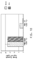
- Figure 1 depicts one embodiment of the article of the present invention.
- the article of the invention therein depicted comprises a porous nanoweb separator, 1, consisting essentially of polyimide nanofibers consisting essentially of a fully aromatic polyimide, disposed between a negative electrode, 2, and a positive electrode, 3, each electrode being deposited on a non-porous conductive metallic foil, 4a and 4b respectively.
- the negative electrode, 2, comprises carbon, preferably graphite
- the metallic foil 4a is copper foil.
- the positive electrode, 3, is lithium cobalt oxide, lithium iron phosphate, or lithium manganese oxide and the metallic foil 4b is aluminum foil.
- the multi-layer article comprises
- the first layer is copper foil and the second layer is carbon, preferably graphite.
- the third layer is a nanoweb consisting essentially of nanofibers of PMDA/ODA.
- the fourth layer is lithium cobalt oxide and the fifth layer is aluminum foil.
- the first layer is copper foil
- the second layer is carbon, preferably graphite
- the third layer is a nanoweb consisting essentially of nanofibers of PMDA/ODA
- the fourth layer is lithium cobalt oxide and the fifth layer is aluminum foil.
- the foil is coated on both sides with the positive or negative electrode-active material.
- the stack so-depicted comprises a plurality of interconnected multi-layer articles of the invention as depicted in Figure 1 .
- a plurality of porous polyimide nanoweb separators, 1 are stacked with alternating layers of negative electrodes, 2, and positive electrodes, 3.
- the negative electrode material, 2, is carbon, preferably graphite, deposited upon both sides of copper foil, 4a, and the positive electrode material, 3, is lithium cobalt oxide deposited upon both sides of aluminum foil, 4b.
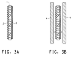
- the article of the invention comprises the porous nanoweb separator suitable for use in the present invention, 1, consisting essentially of nanofibers of a fully aromatic polyimide, disposed between a negative electrode, 2, and a positive electrode, 3, each electrode being deposited directly upon opposite sides of the nanoweb.
- the electrode materials are deposited onto the nanoweb by methods such as are well known in the art including paste extrusion, printing.
- the negative electrode comprises carbon, preferably graphite
- the positive electrode comprises lithium cobalt oxide, lithium iron phosphate, or lithium manganese oxide, preferably lithium cobalt oxide.
- Figure 3b A further embodiment of the configuration of Figure 3a is depicted in Figure 3b wherein a layer of metallic foil, 4, is added to the structure of Figure 3a , as shown.
- the multi-layer structure of Figure 3b is subject to lamination to provide intimate surface to surface contact and adhesion among the layers.
- the electrochemical cell of the invention is formed when the layered stack, shown in Figure 2 , is housed in a liquid-tight housing, 5 , which can be a metallic "can," that contains a liquid electrolyte, 6.
- the liquid electrolyte comprises an organic solvent and a lithium salt soluble therein.
- the lithium salt is LiPF 6 , LiBF 4 or LiClO 4 .
- the organic solvent comprises one or more alkyl carbonates.
- the one or more alkyl carbonates comprises a mixture of ethylene carbonate and dimethylcarbonate.
- the solvent is 70 parts by volume ethylene carbonate and 30 parts by volume dimethyl carbonate and the salt is LiPF 6 .
- the electrolyte salt may comprise lithium hexafluoroarsenate, lithium bis-trifluoromethyl sulfonamide, lithium bis(oxalate)boronate, lithium difluorooxalatoboronate, or the Li + salt of polyfluorinated cluster anions, or combinations of these.
- the electrolyte solvent may comprise propylene carbonate, esters, ethers, or trimethylsilane derivatives of ethylene glycol or poly(ethylene glycols) or combinations of these.
- the electroyte may contain various additives known to enhance the performance or stability of Li-ion batteries, as reviewed for example by K. Xu in Chem. Rev., 104, 4303 (2004 ), and S.S. Zhang in J. Power Sources, 162,1379 (2006 )..
- the stack depicted in Figure 2 can be replaced by the multi-layer article depicted in Figure 1 .
- the output voltage from the stack is equal to the combined voltage from each cell.
- the individual cells making up the stack are electrically connected in parallel, the output voltage from the stack is equal to the voltage of one cell.
- the average practitioner of the electrical art will know when a series arrangement is appropriate, and when a parallel.
- Lithium ion batteries are available in a variety of forms including cylindrical, prismatic, pouch, wound, and laminated. Lithium-ion batteries find use in a variety of different applications (e.g. consumer electronics, power tools, and hybrid electric vehicles). The manufacturing process for lithium ion batteries is similar to that of other batteries such as NiCd and NiMH, but is more sensitive because of the reactivity of the materials used in Li-ion batteries.
- the positive and negative electrodes in lithium ion cells suitable for use in one embodiment of the present invention are similar in form to one another and are made by similar processes on similar or identical equipment.
- active material is coated onto both sides of a metallic foil, preferably Al foil or Cu foil, which acts as current collector, conducting the current in and out of the cell.
- the negative electrode is made by coating graphitic carbon on copper foil.
- the positive electrode is made by coating a lithium metal oxide (e.g. LiCoOz) on Al foil.
- the thus coated foils are wound on large reels and are dried at a temperature in the range of 100-150 °C before bringing them inside a dry room for cell fabrication.
- the active material, 41 is combined with a binder solution, 42, and conductive filler, 43, such as acetylene black.
- a binder solution, 42 such as acetylene black.
- conductive filler, 43 such as acetylene black.
- the combination so formed is fed through a precision regulator, 44, to a mixing tank, 45 , wherein the combination is mixed until it gives a homogeneous appearance.
- Suitable binders include but are not limited to poly(vinylidene fluoride) homopolymer and copolymer, styrene butadiene rubber, polytetrafluoroethylene, and polyimide.
- the thus formed slurry is then gravity fed or pressure fed to a pump, 46, which pumps the slurry through a filter, 47, and thence to a coating head, 48.
- the coating head deposits a controlled amount of the slurry onto the surface of a moving metal foil, 49, being fed from a feed roll, 410.
- the thus coated foil is conveyed by a series of rolls, 411, through an oven, 412, set at 100 to 150°C.
- a knife edge, 413, disposed at the entrance of the oven is positioned an adjustable distance above the foil; the thickness of the electrode formed thereby is controlled by adjusting the gap between the knife edge and the foil..
- the solvent is volatilized, typically through a solvent recovery unit, 414.
- the thus dried electrode is then conveyed to a wind-up roll, 415 .
- the electrode thickness achieved after drying is typically in the range of 50 to 150 micrometers. If it is desired to produce a coating on both sides of the foil, the thus one-side coated foil is fed back into the coating machine, but with the uncoated side disposed to receive the slurry deposition. Following coating, the electrodes so formed are then calendered and optionally slit to narrow strips for different size batteries. Any burrs on the edges of the foil strips could give rise to internal short circuits in the cells so the slitting machine must be very precisely manufactured and maintained.
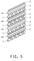
- the electrode assembly hereof is a spiral wound structure used in cylindrical cells.
- a structure suitable for use in a spiral wound electrode assembly is shown in Figure 5 .
- the electrode assembly hereof is a stacked structure like that in Figure 2 , suitable for use in in prismatic cells.
- Prismatic cells can be made in wound form also. In the case of a prismatic cell, the wound cell is pressed to form a rectangular structure, which is then pushed inside a rectangular housing.
- the electrode assembly is first wound into a spiral structure as depicted in Figure 5 . Then a tab is applied to the edge of the electrode to connect the electrode to its corresponding terminal.
- a tab is applied to the edge of the electrode to connect the electrode to its corresponding terminal.
- the tabs are then welded to the can and the spirally wound electrode assembly is inserted into a cylindrical housing. The housing is then sealed but leaving an opening for injecting the electrolyte into the housing.
- the cells are then filled with electrolyte and then sealed.
- the electrolyte is usually a mixture of salt (LiPF6) and carbonate based solvents.
- Cell assembly is preferably carried out in a "dry room” since the electrolyte reacts with water. Moisture can lead to hydrolysis of LiPF 6 forming HF, which can degrade the electrodes and adversely affect the cell performance.
- the cell After the cell is assembled it is formed (conditioned) by going through at least one precisely controlled charge/discharge cycle to activate the working materials. For most lithium ion chemistries, this involves creating the SEI (solid electrolyte interface) layer on the negative (carbon) electrode. This is a passivating layer which is essential to protect the lithiated carbon from further reaction with the electrolyte.
- SEI solid electrolyte interface
- the multi-layer article of the invention comprises a nanoweb that is an enhanced nanoweb as described infra.
- the electrochemical cell hereof comprises a nanoweb separator that is an enhanced nanoweb as described infra.
- an enhanced nanoweb is characterized by a crystallinity index of at least 0.2.
- the enhanced nanoweb is an enhanced nanoweb consisting essentially of nanofibers of PMDA/ODA having a crystallinity index of at least 0.2.
- a method for preparing a nanoweb wherein the nanoweb includes a plurality of nanofibers wherein the nanofibers consist essentially of a fully aromatic polyimide.
- the nanoweb prepared may be an enhanced nanoweb, by which is meant a nanoweb with higher strength, lower electrolyte solvent uptake, and reduced electrolyte solvent-induced loss in physical properties.
- the enhanced nanoweb hereof is characterized by a crystallinity index of at least 0.2.
- crystallinity index as it is employed herein is defined infra.
- High strength and toughness is a vital characteristic in lihium ion batteries, as discussed supra. Retention of those properties in use-namely in the presence of electrolyte solvents - is just as important. While the nanoweb separators of the invention provide a superior degree of strength, toughness, and retention thereof upon solvent exposure, the enhanced nanoweb separators of the invention provide further improvements to the nanowebs consisting essentially of nanofibers of fully aromatic polyimides. While not limiting the invention, it is believed that the observed enhancement in properties is at least partially accounted for by the increase in crystallinity that is provided in the enhanced nanowebs hereof.
- Lithium ion batteries that incorporate the nanoweb separators of the invention are superior in durability in regard to both thermal stress and mechanical shock over those of the art. Lithium ion batteries that incorporate the enhanced nanoweb separators of the invention are further improved.
- the enhanced nanoweb separator of the invention is prepared by heating a nanoweb consisting essentially of nanofibers of a fully aromatic polyimide to a temperature within an annealing range and is made to exhibit enhanced crystallinity, strength, and reduced solvent uptake.
- the annealing range depends highly on the composition of the material.
- the annealing range is 400-500°C for PMDA/ODA.
- BPDA/RODA it is around 200°C; BPDA/RODA will decompose if heated to 400°C.
- the annealing range begins at least 50°C above the imidization temperature thereof.
- the imidization temperature for a given polyamic acid nanoweb is the temperature below 500°C at which in thermogravimetric analysis, at a heating rate of 50°C/min, the % weight loss/°C decreases to below 1.0, preferably below 0.5 with a precision of ⁇ 0.005% in weight % and ⁇ 0.05°C.
- the fully aromatic polyimide nanoweb is subject to heating in the annealing range for a period of time from 5 seconds to 20 minutes, preferably from 5 seconds to 10 minutes.
- a PMDA/ODA amic acid nanoweb produced by condensation polymerization from solution followed by electroblowing of the nanoweb is first heated to ca. 100°C in a vacuum oven with a nitrogen purge to remove residual solvent. Following solvent removal, the nanoweb is heated, preferably in an inert atmosphere such as argon or nitrogen, to a temperature in the range of 300-350°C and held for a period of less than 15 minutes, preferably less than 10 minutes, more preferably less than 5 minutes, most preferably less than 30 seconds until at least 90% of the amic functionality has been converted (imidized) to imide functionality, preferably until 100% of the amic functionality has been imidized.
- an inert atmosphere such as argon or nitrogen
- the thus imidized nanoweb is then heated to a temperature in the range of 400 - 500°C, preferably in the range of 400 - 450°C, for a period of 5 seconds to 20 minutes, until a crystallinity index of 0.2 is achieved..
- the invention provides an electrochemical double layer capacitor (EDLC).
- EDLCs are energy storage devices having a capacitance that can be as high as several Farads.
- Charge storage in double-layer electrochemical capacitors is a surface phenomenon that occurs at the interface between the electrodes, typically carbon, and the electrolyte.
- the separator absorbs and retains the electrolyte thereby maintaining close contact between the electrolyte and the electrodes.
- the role of the separator is to electrically insulate the positive electrode from the negative electrode and to facilitate the transfer of ions in the electrolyte, during charging and discharging.
- Electrochemical double layer capacitors are typically made in a cylindrically wound design in which the two carbon electrodes and separators are wound together, separators having high strength are desired to avoid short-circuits between the two electrodes.
- crystallinity index refers to a relative crystallinity parameter determined from Wide-Angle X-ray Diffraction (WAXD).
- WAXD Wide-Angle X-ray Diffraction
- X-ray diffraction data were collected with a PANalytical X'Pert MPD equipped with a Parabolic X-ray Mirror and Parallel Plate Collimator.using Copper radiation.
- Samples for transmission geometry were prepared by stacking the thin films to a total thickness of approximately 0.7mm. Data were collected over a range of two-theta of 3 to 45 degrees with a step size of 0.1 degree.
- Count time per data point was 10 seconds minimum with the sample rotating about the transmission axis at a rate of 0.1 revolutions per second.
- the WAXD scan so generated consisted of three contributions: 1) a background signal; 2) scattering from ordered but amorphous regions; 3) scattering from crystalline regions.
- a polynomial background was fitted to the baseline of the diffraction data.
- the background function was chosen to be a third order polynomial in the two-theta diffraction angle variable.
- the background subtracted data was then least squares fitted with a series of Gaussian peaks which represented either ordered amorphous or crystalline components. Guided by experience with numerous samples of the same composition but widely differing in crystallinity, it was decided which peaks represented the crystalline regions.
- the ratio of the integral under the crystalline peaks so selected, to the integral under the overall scan curve with the background subtracted was the crystallinity index.
- the infrared spectrum of a given sample was measured, and the ratio of the imide C-N absorbance at 1375 cm -1 to the p-substituted C-H absorbance at 1500 cm -1 was calculated. This ratio was taken as the degree of imidization (DOI). It has been found that a PMDA/ODA polyamic acid nanoweb that has been subject to imidization conditions for a time well in excess of that thought to be necessary to achieve maximum imidization exhibits a DOI of about 0.57 By comparison, a PMDA/ODA film sample had a DOI of 0.65. The difference may be attributable to sample effects, such as orientation in the nanofibers that is not present in the film.
- the DOI was calculated by taking the 1375/1500 cm -1 peak ratio of 0.57 to represent a 100% imidized PMDA/ODA nanoweb. To determine % imidization of a given sample, the ratio of the 1375/1500 peaks was calculated as a percentage of 0.57.
- the polyimide nanowebs hereof were analyzed by ATR-IR using a DuraSampl IR (ASI Applied Systems) accessory on a Nicolet Magna 560 FTIR (ThermoFisher Scientific). Spectra were collected from 4000-600 cm-1 and were corrected for the ATR effect (depth of penetration versus frequency).
- a 1 cm square specimen was placed horizontally on top of a piece of crumpled aluminum foil in a sealed, 20 mL scintillation vial, that contained 1.5 mL of a 70/30 (v/v) mixture of ethyl methyl carbonate and ethylene carbonate.
- the samples were thus suspended above the liquid mixture, and only allowed to contact solvent vapor.
- samples were removed from the vial, weighed quickly on a microbalance, and returned to the sealed vial.
- Solution viscosity was determined using a Brookfield Engineering HADV-II+ Programmable Viscometer equipped with an RV/HA/HB-5 or - 6 spindle, and calibrated using NIST traceable silicone fluids.
- the spindle was immersed into the room temperature polymer solution until the liquid level reached the indent on the spindle.
- the motor was turned on with the RPMs set to produce 10-20% nominal torque. For solutions of 40-70 poise, it was found that 10-20 rpm was appropriate with the RV/HA/HB-5 spindle.and 20 rpm was appropriate for HA/HB-6 spindle.
- Nanofiber diameter was determined using the following method.
- P84 and P84HT available from HP Polymers.
- P84 is a co-condensate of 2,4 TDI/2,6 TDI/ MDI with BTDA.
- P84HT is a co-condensate of 2,4 TDI/2,6 TDI with BTDA/PMDA.
- Electrospinning is a well-known technology, described, for example, in The Encyclopedia of Polymer Science and Technology , DOI 10.1002/0471440264.pst554. It is found in the art of electrospinning that spinning becomes unstable and the fibers begin to "whip around". As a result of the whipping action, the fiber diameter is decreased to the desired range.
- the productivity of electrospinning is extremely low, typically in the range of ml per hour from a single spinning point. The technique of so-called electroblowing was introduced to attempt to remedy the productivity problem in electrospinning thin fibers.
- Electroblowing In electroblowing, a turbulent air flow is directed to the fibers as they are spun thereby forming a "cloud" of polymer fibers that is blown down onto the target surface as well as being electrostatically attracted. The combination of blowing and electrostatic forces greatly increases the productivity of the system. Electroblowing is described in detail in U.S. Published Patent Application 2005/0067732 .
- Nanowebs were prepared from the poly(amic acid) solutions prepared supra by electroblowing.
- Figure 6 depicts one embodiment of suitable electroblowing apparatus.
- PAA solution was pumped from drums into a stirred storage tank, not shown, through a 25 micrometer screen, not shown.
- the PAA solution from the storage tank was charged to a gear pump, not shown, using pressurized air, not shown.
- the gear pump then fed a spinning beam, 102, having 76 spinning nozzles arrayed in a 1 m wide spinnerette, with the nozzles spaced 1 cm apart.
- a DC voltage difference was applied between the spinneret and a grounded collector, 110.
- Compressed air from an air compressor which served as a process gas was passed through a heater, not shown, fed into the spinneret and ejected from the spinneret via air slots, 106, disposed in the sides of the knife edge of the spinneret containing the spinning nozzles.
- Each spinning nozzle was characterized by a diameter, d, of 0.25 mm, and a length of 2.5 mm.
- An air blower, 112 was connected by a length of tubing to a perforated air collecting table 114 to create a vacuum under a 1 m wide steel mesh conveyor, 110, driven by a roller, 116, and supported by 3 other turning rollers, 115 .
- the fibers, 103 were both blown by the air and attracted by the electric potential to form a web, 105 , on the surface of the steel mesh collector conveyor, 110.
- the web was passed through a hot air dryer, 107, and wound up on a winder, 106.
- a second electroblowing apparatus was depicted in Figure 7 .
- the polymer solution was manually loaded using a syringe, not shown, into a 250 ml Hoke cylinder, 200.
- a pressurized nitrogen supply, 201 was used to deliver the solution to a 10 cm wide spinneret, 102, having 3 nozzles each with a diameter of 0.38mm and length 3.8mm, arranged 1 cm apart, centered in the spinneret.
- Heated, compressed air, 108 was fed to the spinneret and was ejected through slots, 106.
- the fibers, 103 are both blown by the air and attracted by a DC voltage electric potential to a metallic plate collector, 202 which maintains the ground connection to a battery operated windup, 203.
- a roll of scrim material, 204 was mounted on the end of the plate collector. Heated, pressurized air, 205 , also blown into a Plexiglas® enclosure, 207, containing the entire spinning apparatus. An exhaust blower, 206, was used to maintain atmospheric pressure inside the enclosure and to remove all evaporated solvent.
- the numbered parts that are common to both Figures 6 and 7 are the same in both.
- PAA - 1 50 kg of PAA - 1 was charged to the apparatus described and discharged from the spinning nozzles, 104, at a discharge pressure of 3.5 bar and a temperature of 39 °C.
- Process gas was expelled at a velocity of 5,042 m/min at 69°C from the slots, 106, with a gap, dimension "a", of 0.7mm.
- the product was collected in the form of a web of nanofibers on the electrically grounded collector belt, 110.
- the distance from the nozzles to the collector was 30 cm.
- the applied potential difference was 85 kV.
- the nanoweb, 105 was passed through a hot air dryer, 107, at 180 °C for 3 minutes.
- the thus dried nanoweb was then wound into a roll.
- the thus prepared polyamic acid nanoweb was then unwound, and then imidized by heating in a Glenro medium wavelength infrared oven to a temperature of about 325C for 1 1 ⁇ 2 minutes and rewound.
- the web was then unwound and calendered on a BF Perkins calender at a pressure of 1800 pounds per linear inch between a stainless steel calender roll and a cotton covered calender roll and then rewound..
- PAA-4 - PAA-12 were employed in the preparation of nanowebs using the equipment and procedures employed in preparing NW - 3. Specific ingredients and conditions are summarized in Table 4. Table 4 Polymer # Spinning # process gas temp C process gas flow cfm process gas vel m/min soln temp C solution feed pressure psi aux air temp C aux air flow cfm Quantity of solution cc PAA-3 NW-3 22 19 4480 24 32 102 9 50 PAA-4 NW-4 20 17 4009 24 40 100 14 50 PAA-4 NW-5 20 19 4480 26 40 70 34 50 PAA-5 NW-6 20 19 4480 20 20 103 14 60 PAA-6 NW-7 20 17 4009 25 110 114 12 50 PAA-7 NW-8 23 12 2830 27 150 115 12 30 PAA-8 NW-9 21 19 4480 27 120 70 19 1 30,35,35 50 PAA-9 NW-10 21 19 4480 26 60 70 9-24 PAA-10 NW-11 24 19 4480 28 65 70 34 50 PAA-11 NW-12 23 10 2358 24 35 70 10 30 PAA-12 NW-13 19 10 2358
- Nanowebs were further prepared from the non-fully aromatic comparative polymers, P84 and P84HT. These were designated CNW 1 - 3.
- the resulting webs were peeled from the scrim and manually cut into hand sheets approximately 12" long and 4" wide.
- the hand sheets were then dried in a convection oven allowed to cool, then calendered on a BF Perkins calender at a pressure of 1500 pounds per linear inch between a steel calender roll and a cotton covered calender roll.
- One of the CNW-B sheets were then reheated in a convection oven to a temperature of 400°C for two minutes. See Table 6 for post processing settings.
- Table 6 Nanoweb # Drying Temp (°C) Drying Time (min) Annealing Temp. (°C) CNW-A 200 30 none CNW-B 200 2 400 CNW-B 200 2 none CNW-C 200 2 none CNW-D 180 5 none
- Example 1 having a crystallinity index below 0.2 is not according to the invention.
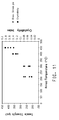
- Table 7 Example Time Elapsed (min) Approximate Maximum Temperature (°C) DOI C.I. Solvent Uptake (%) 1 0.2 325 0.93 0.11 22.5 2 5.3 370 0.94 0.25 21.2 3 10.5 410 0.91 0.36 19.5 4 42 450 0.92 0.40 18.8
- Coin cells type CR2032 were assembled from commercial parts (Pred Materials International, Inc., New York, NY 10165) together with the following components:
- the positive electrode was LiCoO 2 on Al foil, 60 ⁇ 3 ⁇ m thick (Japan Pionics Co. Ltd., distributed by Pred Materials International), 1.5 ⁇ 0.1mAh/cm 2 as disks 9/16" in diameter.
- the electrolyte solution was 1.0M LiPF 6 in a 2:1 by weight mixture of ethylene carbonate/ethyl methyl carbonate (Ferro), was stored and dispensed in an Ar glove box.
- Porous polyolefin (Celgard LLC, Charlotte, NC 28273) as disks 11/16" in diameter was used as a comparative example to represent a current commercial separator.
- the cell hardware were dried overnight at 90°C under reduced pressure and transferred into an Ar-filled glove box for storage, filling and assembly.
- the cells were assembled with two layers of separator inserted between negative electrode and positive electrode, filled with electrolyte solution, sealed by means of a crimped polyolefin gasket and removed from the glove box.
- the dried and calendered, but not yet imidized, nanoweb specimens of PAA nanofibers were then heated by placing the sample on a metal tray lined with Kapton® film and then placing the tray with the sample on it in a laboratory convection oven preheated to temperatures ranging from 200 °C to 475 °C for 2 minutes.
- the mean fiber diameter from the sample heated at 475C for 2 minutes was 707 nm and the porosity was 50.5%.
- the sample with no additional heating had a mean fiber diameter of 775 nm and a porosity of 50.8%
- Examples 5-1 to 5-5 whose crystallinity index is below 0.2 are not according to the invention.
- Table 9 Example Anneal Temp Tensile DOI C.I. Basis Wt C (psi) (%) gsm 5-1 180 1077 29.3 0.06 18.4 5-2 200 1193 39.5 0.04 18.1 5-3 250 3441 84.4 0.05 17.5 5-4 300 4841 96.5 0.11 17 5-5 350 5047 97.9 0.14 16.3 5-6 400 5793 95.8 0.25 16 5-7 425 6461 98.6 0.22 16 5-8 450 7167 95.1 0.33 16 5-9 475 7427 94.4 0.4 16
- Nanowebs #3, 5, 7, 8, 9, 10, and 11, were dried in an air convection oven at 200 °C for 2 minutes. They were then subject to calendering, imidization, and annealing according to the conditions shown in Table 10.
- Table 10 Calendering Imidization Annealing Nano web # pressure (pli) Before/After Imidization Temp. °C time (min) Temp. (°C) time (min) 3 1500 Before 350 2 450 2 5 1500 Before 220 30 na Na 7 1500 Before 350 2 450 2 8 1500 Before na na na Na 9 750 After 275 10 na Na 10 1500 Before 350 2 450 2 11 1500 Before 350 2 450 2
- Examples 14-1 to 14-4 whose crystallinity index is below 0.2, are not according to the invention.
- Table 14 Example Anneal Temp Break Stress Crys C Kg/cm 2 Index 14-1 220 253 0.04 14-2 300 255 0.05 14-3 400 330 0.14 14-4 450 378 0.18
- cap, gaskets, wave springs, and spacer disk for a type 2032 coin cell (Hohsen Corp., Osaka Japan via Pred Materials, New York, USA.) were stored in a glovebox (Vacuum Atmosphere Company, Hawthorne, CA) operated with an Argon atmosphere.
- Two 0.625 inch diameter commercial grade carbon- coated (activated carbon with PTFE binder) aluminum foil electrodes were punched out of a sheet thereof.
- the electrode disks so prepared were dried at 90 °C for 18 hrs in a vacuum oven (Neytech, Model Number 94-94-400).
- Electrolyte solution (Digirena ® 1 M tetraethyl ammonium tetrafluoroborate in acetonitrile) was obtained from Honeywell (Morristown, NJ).
- the coin cell was assembled inside the glove box.
- the PP gaskets were pushed into the top cap.
- a first carbon electrode disk was placed in the coin cell case and four drops of electrolyte were added using a plastic pipette.
- Two layers of the NW-3 disks were then placed on top of the wet electrode, followed by a second carbon electrode.
- Four drops of the electrolyte were added to the second electrode.
- a spacer disk was placed on the second carbon electrode followed by the wave spring and gasketed cap.
- the thus assembled coin cell was crimped using an automated coin cell crimper (Hohsen Corporation, Model No HSACC-D2032). Excess electrolyte was wiped off the exterior of the coin cell, and the cell was removed from the glove box for further conditioning and electrochemical testing.
- the 2032 coin cell electronic double layer capacitors are tested by cycling them between 1.0 V and 2.5V at 10 mA current for 5 cycles. All the cycling tests (constant current charging at 10 mA followed by constant current discharging at 10 mA, separated by 15 minute rest steps) were done using a Maccor 32 channel cycler (model 4000). The charge and discharge capacitance for cycle number 4 and 5 are shown in Table 16. Table 16 Cycle Number Charge Capacitance (F) Discharge Capacitance (F) Four 2.605 2.573 Five 2.760 2.570
Landscapes
- Chemical & Material Sciences (AREA)
- Chemical Kinetics & Catalysis (AREA)
- Electrochemistry (AREA)
- General Chemical & Material Sciences (AREA)
- Engineering & Computer Science (AREA)
- Materials Engineering (AREA)
- Power Engineering (AREA)
- Manufacturing & Machinery (AREA)
- Inorganic Chemistry (AREA)
- Microelectronics & Electronic Packaging (AREA)
- Ceramic Engineering (AREA)
- Secondary Cells (AREA)
- Cell Separators (AREA)
- Battery Electrode And Active Subsutance (AREA)
- Electric Double-Layer Capacitors Or The Like (AREA)
- Cell Electrode Carriers And Collectors (AREA)
- Laminated Bodies (AREA)
- Nonwoven Fabrics (AREA)
Claims (11)
- Article multicouche comprenant un premier matériau d'électrode, un second matériau d'électrode, et un séparateur poreux disposé entre et en contact avec le premier et le second matériaux d'électrode, où le séparateur poreux comprend une nanobande qui comprend une pluralité de nanofibres, où les nanofibres sont essentiellement constituées d'un polyimide entièrement aromatique, et où le polyimide entièrement aromatique est caractérisé par un indice de cristallinité de 0,2 ou plus.
- Article multicouche selon la revendication 1 où le polyimide entièrement aromatique comprend du PMDA/ODA.
- Article multicouche selon la revendication 1 où le premier matériau d'électrode, le séparateur, et le second matériau d'électrode se trouvent mutuellement en contact par adhérence sous la forme d'un stratifié.
- Article multicouche selon la revendication 1 comprenant en outre au moins un collecteur métallique de courant en contact par adhérence avec au moins l'un du premier ou du second matériaux d'électrode.
- Article multicouche selon la revendication 4 comprenant en outre
une première couche comprenant un premier collecteur métallique de courant;
une seconde couche comprenant le premier matériau d'électrode, en contact par adhérence avec le premier collecteur métallique de courant;
une troisième couche comprenant le séparateur poreux, en contact par adhérence avec le premier matériau d'électrode;
une quatrième couche comprenant le second matériau d'électrode, contactant le séparateur poreux par adhérence; et,
une cinquième couche comprenant un second collecteur métallique de courant, contactant le second matériau d'électrode par adhérence. - Article multicouche selon la revendication 5 où le premier collecteur métallique de courant comprend une feuille de cuivre, le premier matériau d'électrode comprend du carbone, le polyimide entièrement aromatique comprend du PMDA/ODA, le second matériau d'électrode comprend de l'oxyde de lithium cobalt, et le second collecteur métallique de courant comprend une feuille d'aluminium.
- Article multicouche selon la revendication 1 où le premier et le second matériaux d'électrode sont le même matériau.
- Article multicouche selon la revendication 1 où le premier et le second matériaux d'électrode sont un matériau différent.
- Article multicouche selon la revendication 5 où le premier et le second matériaux d'électrode sont le même matériau.
- Article multicouche selon la revendication 5 où le premier et le second matériaux d'électrode sont un matériau différent.
- Article multicouche selon la revendication 5 où le premier et le second collecteurs métalliques de courant comprennent une feuille d'aluminium; le premier et le second matériaux d'électrode comprennent du carbone; et le polyimide entièrement aromatique comprend du PMDA/ODA.
Applications Claiming Priority (2)
| Application Number | Priority Date | Filing Date | Title |
|---|---|---|---|
| US28661809P | 2009-12-15 | 2009-12-15 | |
| PCT/US2010/060051 WO2011081875A2 (fr) | 2009-12-15 | 2010-12-13 | Article multicouche à nanobande en polyimide |
Publications (3)
| Publication Number | Publication Date |
|---|---|
| EP2514003A2 EP2514003A2 (fr) | 2012-10-24 |
| EP2514003A4 EP2514003A4 (fr) | 2015-10-21 |
| EP2514003B1 true EP2514003B1 (fr) | 2016-11-02 |
Family
ID=44143305
Family Applications (1)
| Application Number | Title | Priority Date | Filing Date |
|---|---|---|---|
| EP10841501.9A Active EP2514003B1 (fr) | 2009-12-15 | 2010-12-13 | Article multicouche à nanobande en polyimide |
Country Status (9)
| Country | Link |
|---|---|
| US (2) | US8557444B2 (fr) |
| EP (1) | EP2514003B1 (fr) |
| JP (2) | JP2013513931A (fr) |
| KR (1) | KR101886878B1 (fr) |
| CN (1) | CN102754241B (fr) |
| BR (1) | BR112012014254A2 (fr) |
| IN (1) | IN2012DN05005A (fr) |
| TW (1) | TWI500207B (fr) |
| WO (1) | WO2011081875A2 (fr) |
Families Citing this family (36)
| Publication number | Priority date | Publication date | Assignee | Title |
|---|---|---|---|---|
| JP6138687B2 (ja) | 2010-09-09 | 2017-05-31 | カリフォルニア インスティチュート オブ テクノロジー | 電気化学エネルギー貯蔵システム及びその方法 |
| US9666848B2 (en) | 2011-05-20 | 2017-05-30 | Dreamweaver International, Inc. | Single-layer lithium ion battery separator |
| US9379368B2 (en) | 2011-07-11 | 2016-06-28 | California Institute Of Technology | Electrochemical systems with electronically conductive layers |
| CN103650204B (zh) | 2011-07-11 | 2016-11-16 | 加州理工学院 | 用于电化学系统的新颖分隔物 |
| US8679200B2 (en) | 2011-11-18 | 2014-03-25 | E I Du Pont De Nemours And Company | Method for reducing self discharge in an electrochemical cell |
| WO2014020545A1 (fr) | 2012-07-30 | 2014-02-06 | Sabic Innovative Plastics Ip B.V. | Séparateur résistant à une fusion à haute température |
| CN103682247B (zh) * | 2012-09-24 | 2017-02-08 | 华为技术有限公司 | 一种锂离子电池用复合负极片及其制备方法和锂离子电池 |
| US10700326B2 (en) | 2012-11-14 | 2020-06-30 | Dreamweaver International, Inc. | Single-layer lithium ion battery separators exhibiting low shrinkage rates at high temperatures |
| JP5912190B2 (ja) | 2012-12-12 | 2016-04-27 | エルジー・ケム・リミテッド | 二次電池用電極、それを含む二次電池及びケーブル型二次電池 |
| KR101479460B1 (ko) * | 2012-12-12 | 2015-01-05 | 주식회사 엘지화학 | 이차전지용 전극, 그를 포함하는 이차전지 및 케이블형 이차전지 |
| KR101371061B1 (ko) * | 2013-03-14 | 2014-03-10 | (주)에프티이앤이 | 내열성이 향상된 이차전지용 2층 분리막 및 이의 제조방법 |
| US10607790B2 (en) | 2013-03-15 | 2020-03-31 | Dreamweaver International, Inc. | Direct electrolyte gelling via battery separator composition and structure |
| CN103199217B (zh) * | 2013-04-02 | 2015-06-03 | 东莞新能源科技有限公司 | 锂离子电池的富锂极片及其制备方法 |
| CN104124414B (zh) * | 2013-04-28 | 2017-06-20 | 华为技术有限公司 | 一种锂离子电池复合电极片及其制备方法和锂离子电池 |
| US20140356703A1 (en) * | 2013-06-03 | 2014-12-04 | E I Du Pont De Nemours And Company | Electrochemical cell comprising a nanoweb comprising nanofibers of a cross-linked polyimide |
| CN104342850B (zh) * | 2013-08-08 | 2017-03-15 | 北京纳迅科技股份有限公司 | 含纳米晶体纤维素的聚酰亚胺膜及其制备方法 |
| US9735410B2 (en) | 2013-11-05 | 2017-08-15 | E I Du Pont De Nemours And Company | Composite separator for electrochemical cell capable of sustained shutdown |
| US10714724B2 (en) | 2013-11-18 | 2020-07-14 | California Institute Of Technology | Membranes for electrochemical cells |
| US9991492B2 (en) | 2013-11-18 | 2018-06-05 | California Institute Of Technology | Separator enclosures for electrodes and electrochemical cells |
| WO2015085580A1 (fr) * | 2013-12-13 | 2015-06-18 | GM Global Technology Operations LLC | Intégration d'électrodes de références dans des cellules de poches de batterie |
| KR20150122320A (ko) * | 2014-04-22 | 2015-11-02 | 한국전자통신연구원 | 커패시터 및 이의 제조 방법 |
| JP6269373B2 (ja) * | 2014-07-29 | 2018-01-31 | 日立金属株式会社 | エナメル線の製造方法及び製造装置 |
| US20160164057A1 (en) * | 2014-12-05 | 2016-06-09 | E I Du Pont De Nemours And Company | Electrochemical cell with polyimide separator and high-voltage positive electrode |
| US10707526B2 (en) | 2015-03-27 | 2020-07-07 | New Dominion Enterprises Inc. | All-inorganic solvents for electrolytes |
| CN107614771A (zh) * | 2015-04-03 | 2018-01-19 | 株式会社未来科学 | 纳米纤维结构 |
| US10340528B2 (en) | 2015-12-02 | 2019-07-02 | California Institute Of Technology | Three-dimensional ion transport networks and current collectors for electrochemical cells |
| TWI680873B (zh) * | 2016-07-01 | 2020-01-01 | 長興材料工業股份有限公司 | 聚醯亞胺乾膜及其用途 |
| TWI687311B (zh) * | 2016-07-01 | 2020-03-11 | 長興材料工業股份有限公司 | 聚醯亞胺乾膜及其用途 |
| JP2018037311A (ja) * | 2016-08-31 | 2018-03-08 | 住友化学株式会社 | 非水電解液二次電池用セパレータの製造方法 |
| US10707531B1 (en) | 2016-09-27 | 2020-07-07 | New Dominion Enterprises Inc. | All-inorganic solvents for electrolytes |
| DE102018205994A1 (de) | 2018-04-19 | 2019-10-24 | Bayerische Motoren Werke Aktiengesellschaft | Hochstromseparator |
| KR102080577B1 (ko) * | 2018-06-04 | 2020-02-24 | (주)씨오알엔 | 나노 섬유 분리막의 제조 방법 및 전해액용 첨가제의 제조 방법 |
| WO2020075513A1 (fr) * | 2018-10-12 | 2020-04-16 | 株式会社村田製作所 | Batterie à fil flexible et batterie à fil flexible équipée d'un connecteur |
| CN113454809A (zh) * | 2019-02-28 | 2021-09-28 | 三洋电机株式会社 | 非水电解质二次电池 |
| CN110344123B (zh) * | 2019-06-27 | 2020-08-11 | 东华大学 | 一种用于亚微米纤维/棉混纺纱生产线上的防棉网卷边装置 |
| CN112133873B (zh) * | 2020-09-25 | 2022-06-14 | 东北师范大学 | 一种锰钴氧化物修饰复合隔膜及其制备方法和应用 |
Family Cites Families (30)
| Publication number | Priority date | Publication date | Assignee | Title |
|---|---|---|---|---|
| EP0462282B1 (fr) * | 1989-12-22 | 1996-06-26 | MITSUI TOATSU CHEMICALS, Inc. | Moulage de polyimide |
| JP2883196B2 (ja) | 1990-11-22 | 1999-04-19 | 東邦レーヨン株式会社 | 高性能ポリイミド成形体及びその製造方法 |
| JPH0562893A (ja) | 1991-09-04 | 1993-03-12 | Fujitsu Ltd | レジスト塗布装置の監視方法及びレジスト塗布装置 |
| TW460505B (en) * | 1998-04-27 | 2001-10-21 | Sumitomo Chemical Co | Separator for nonaqueous electrolyte battery and lithium secondary battery made from the same |
| JP3765396B2 (ja) * | 2001-08-20 | 2006-04-12 | ソニー株式会社 | 電池 |
| JP3538756B2 (ja) * | 2001-11-15 | 2004-06-14 | 日本電池株式会社 | 非水電解質二次電池 |
| JP2003157826A (ja) * | 2001-11-21 | 2003-05-30 | Unitika Ltd | 電池用セパレーター |
| US20030152835A1 (en) * | 2002-02-08 | 2003-08-14 | Sankar Dasgupta | Carbon fibre containing negative electrode for lithium battery |
| KR100549140B1 (ko) | 2002-03-26 | 2006-02-03 | 이 아이 듀폰 디 네모아 앤드 캄파니 | 일렉트로-브로운 방사법에 의한 초극세 나노섬유 웹제조방법 |
| US8003725B2 (en) * | 2002-08-12 | 2011-08-23 | Exxonmobil Chemical Patents Inc. | Plasticized hetero-phase polyolefin blends |
| US20040166311A1 (en) | 2003-02-25 | 2004-08-26 | Clemson University | Electrostatic spinning of aromatic polyamic acid |
| JP2004308031A (ja) | 2003-04-03 | 2004-11-04 | Teijin Ltd | ポリアミド酸不織布、それから得られるポリイミド不織布およびそれらの製造方法 |
| JP2004307625A (ja) * | 2003-04-07 | 2004-11-04 | Teijin Ltd | 芳香族ポリアミド多孔膜およびその製造方法 |
| JP4425576B2 (ja) | 2003-06-23 | 2010-03-03 | 日本バイリーン株式会社 | リチウム二次電池用セパレータ及びリチウム二次電池 |
| HUE046297T2 (hu) * | 2003-09-23 | 2020-02-28 | Innolith Assets Ag | Elektrokémiai akkumulátor cella |
| JP4753874B2 (ja) * | 2004-07-01 | 2011-08-24 | 旭化成株式会社 | セルロース不織布 |
| JP5329018B2 (ja) * | 2004-08-20 | 2013-10-30 | 日産自動車株式会社 | 電池用セパレータ |
| US7422623B2 (en) | 2005-03-02 | 2008-09-09 | L'air Liquide, Societe Anonyme A Directoire Et Conseil De Surveillance Pour L'etude Et L'exploitation Des Procedes Georges Claude | Separation membrane by controlled annealing of polyimide polymers |
| CN100577270C (zh) * | 2005-03-30 | 2010-01-06 | 住友化学株式会社 | 多孔膜、其制备方法和应用 |
| JP5347213B2 (ja) * | 2005-03-30 | 2013-11-20 | 住友化学株式会社 | 多孔性フィルムおよび多孔性フィルムの製造方法 |
| US7112389B1 (en) | 2005-09-30 | 2006-09-26 | E. I. Du Pont De Nemours And Company | Batteries including improved fine fiber separators |
| JP2008002011A (ja) | 2006-06-22 | 2008-01-10 | Toyobo Co Ltd | ポリイミド不織布およびその製造方法 |
| KR100820162B1 (ko) | 2006-08-07 | 2008-04-10 | 한국과학기술연구원 | 내열성 초극세 섬유상 분리막 및 그 제조 방법과, 이를 이용한 이차전지 |
| KR100845239B1 (ko) | 2006-08-07 | 2008-07-10 | 한국과학기술연구원 | 내열성 초극세 섬유층을 지닌 분리막 및 이를 이용한이차전지 |
| US20080057390A1 (en) * | 2006-08-31 | 2008-03-06 | Seiko Epson Corporation | Secondary battery |
| EP2065432B2 (fr) * | 2006-09-20 | 2017-10-25 | Asahi Kasei Kabushiki Kaisha | Membrane microporeuse en polyoléfine et séparateur pour batteries à électrolyte non aqueux |
| JP4189827B2 (ja) | 2007-01-11 | 2008-12-03 | 哲夫 内田 | 連発式吹矢玩具装置 |
| US20080241645A1 (en) * | 2007-03-26 | 2008-10-02 | Pinnell Leslie J | Lithium ion secondary batteries |
| JP5535069B2 (ja) * | 2007-07-26 | 2014-07-02 | サビック・イノベーティブ・プラスチックス・アイピー・ベスローテン・フェンノートシャップ | 結晶化可能ポリエーテルイミド類とその製造方法および同材料から誘導される物品 |
| CN101425570A (zh) * | 2007-10-30 | 2009-05-06 | 赢创德固赛有限责任公司 | 电隔离物、其制造方法和用途 |
-
2010
- 2010-10-07 US US12/899,801 patent/US8557444B2/en active Active
- 2010-12-13 JP JP2012544676A patent/JP2013513931A/ja active Pending
- 2010-12-13 IN IN5005DEN2012 patent/IN2012DN05005A/en unknown
- 2010-12-13 CN CN201080063954.7A patent/CN102754241B/zh active Active
- 2010-12-13 WO PCT/US2010/060051 patent/WO2011081875A2/fr active Application Filing
- 2010-12-13 BR BR112012014254A patent/BR112012014254A2/pt not_active IP Right Cessation
- 2010-12-13 EP EP10841501.9A patent/EP2514003B1/fr active Active
- 2010-12-13 KR KR1020127018338A patent/KR101886878B1/ko active IP Right Grant
- 2010-12-15 TW TW099144086A patent/TWI500207B/zh active
-
2013
- 2013-06-26 US US13/927,686 patent/US8852808B2/en active Active
-
2015
- 2015-05-13 JP JP2015098011A patent/JP2015181117A/ja active Pending
Also Published As
| Publication number | Publication date |
|---|---|
| KR101886878B1 (ko) | 2018-08-08 |
| EP2514003A4 (fr) | 2015-10-21 |
| US20130288136A1 (en) | 2013-10-31 |
| EP2514003A2 (fr) | 2012-10-24 |
| KR20120123048A (ko) | 2012-11-07 |
| US8852808B2 (en) | 2014-10-07 |
| WO2011081875A2 (fr) | 2011-07-07 |
| CN102754241A (zh) | 2012-10-24 |
| TW201133990A (en) | 2011-10-01 |
| US8557444B2 (en) | 2013-10-15 |
| BR112012014254A2 (pt) | 2017-07-25 |
| TWI500207B (zh) | 2015-09-11 |
| WO2011081875A3 (fr) | 2011-11-17 |
| US20110143207A1 (en) | 2011-06-16 |
| JP2013513931A (ja) | 2013-04-22 |
| IN2012DN05005A (fr) | 2015-10-02 |
| CN102754241B (zh) | 2016-01-27 |
| JP2015181117A (ja) | 2015-10-15 |
Similar Documents
| Publication | Publication Date | Title |
|---|---|---|
| EP2514003B1 (fr) | Article multicouche à nanobande en polyimide | |
| US20110143217A1 (en) | Electrochemical cell comprising a separator comprising a nanoweb consisting essentially of nanofibers of fully aromatic polyimide | |
| EP2513366B1 (fr) | Procédé d'augmentation de la solidité et de la résistance aux solvants de nanobandes en polyimide | |
| US8518525B2 (en) | Polyimide nanoweb with amidized surface and method for preparing | |
| US20120148896A1 (en) | Multi-layer article of polyimide nanoweb with amidized surface | |
| US9475009B2 (en) | Filtration method using polyimide nanoweb with amidized surface and apparatus therefor | |
| EP2780963A1 (fr) | Procédé pour réduire la décharge spontanée dans une cellule électrochimique | |
| US20120148897A1 (en) | Electrochemical cell comprising a multi-layer article of polyimide nanoweb with amidized surface | |
| US20130125358A1 (en) | Method for reducing self discharge in an electrochemical cell | |
| WO2013181333A1 (fr) | Cellule électrochimique comprenant un nanoréseau contenant des nanofibres d'un polyimide réticulé | |
| EP2727170A1 (fr) | Nanobande en polyimide améliorée |
Legal Events
| Date | Code | Title | Description |
|---|---|---|---|
| PUAI | Public reference made under article 153(3) epc to a published international application that has entered the european phase |
Free format text: ORIGINAL CODE: 0009012 |
|
| 17P | Request for examination filed |
Effective date: 20120605 |
|
| AK | Designated contracting states |
Kind code of ref document: A2 Designated state(s): AL AT BE BG CH CY CZ DE DK EE ES FI FR GB GR HR HU IE IS IT LI LT LU LV MC MK MT NL NO PL PT RO RS SE SI SK SM TR |
|
| DAX | Request for extension of the european patent (deleted) | ||
| A4 | Supplementary search report drawn up and despatched |
Effective date: 20150917 |
|
| RIC1 | Information provided on ipc code assigned before grant |
Ipc: H01M 2/26 20060101ALI20150911BHEP Ipc: H01M 10/0525 20100101ALI20150911BHEP Ipc: H01M 4/133 20100101ALI20150911BHEP Ipc: H01M 4/131 20100101ALI20150911BHEP Ipc: H01M 4/66 20060101ALI20150911BHEP Ipc: H01M 2/16 20060101AFI20150911BHEP |
|
| RAP1 | Party data changed (applicant data changed or rights of an application transferred) |
Owner name: E. I. DU PONT DE NEMOURS AND COMPANY |
|
| RIC1 | Information provided on ipc code assigned before grant |
Ipc: H01M 2/16 20060101AFI20160524BHEP Ipc: H01M 4/66 20060101ALI20160524BHEP Ipc: H01M 4/133 20100101ALI20160524BHEP Ipc: H01M 4/131 20100101ALI20160524BHEP Ipc: H01M 10/0525 20100101ALI20160524BHEP Ipc: H01M 2/26 20060101ALI20160524BHEP |
|
| GRAP | Despatch of communication of intention to grant a patent |
Free format text: ORIGINAL CODE: EPIDOSNIGR1 |
|
| INTG | Intention to grant announced |
Effective date: 20160701 |
|
| GRAS | Grant fee paid |
Free format text: ORIGINAL CODE: EPIDOSNIGR3 |
|
| GRAA | (expected) grant |
Free format text: ORIGINAL CODE: 0009210 |
|
| AK | Designated contracting states |
Kind code of ref document: B1 Designated state(s): AL AT BE BG CH CY CZ DE DK EE ES FI FR GB GR HR HU IE IS IT LI LT LU LV MC MK MT NL NO PL PT RO RS SE SI SK SM TR |
|
| REG | Reference to a national code |
Ref country code: GB Ref legal event code: FG4D |
|
| REG | Reference to a national code |
Ref country code: FR Ref legal event code: PLFP Year of fee payment: 7 |
|
| REG | Reference to a national code |
Ref country code: AT Ref legal event code: REF Ref document number: 842646 Country of ref document: AT Kind code of ref document: T Effective date: 20161115 Ref country code: CH Ref legal event code: EP |
|
| REG | Reference to a national code |
Ref country code: IE Ref legal event code: FG4D |
|
| REG | Reference to a national code |
Ref country code: DE Ref legal event code: R096 Ref document number: 602010037737 Country of ref document: DE |
|
| PG25 | Lapsed in a contracting state [announced via postgrant information from national office to epo] |
Ref country code: LV Free format text: LAPSE BECAUSE OF FAILURE TO SUBMIT A TRANSLATION OF THE DESCRIPTION OR TO PAY THE FEE WITHIN THE PRESCRIBED TIME-LIMIT Effective date: 20161102 |
|
| REG | Reference to a national code |
Ref country code: NL Ref legal event code: MP Effective date: 20161102 |
|
| REG | Reference to a national code |
Ref country code: LT Ref legal event code: MG4D |
|
| REG | Reference to a national code |
Ref country code: AT Ref legal event code: MK05 Ref document number: 842646 Country of ref document: AT Kind code of ref document: T Effective date: 20161102 |
|
| PG25 | Lapsed in a contracting state [announced via postgrant information from national office to epo] |
Ref country code: GR Free format text: LAPSE BECAUSE OF FAILURE TO SUBMIT A TRANSLATION OF THE DESCRIPTION OR TO PAY THE FEE WITHIN THE PRESCRIBED TIME-LIMIT Effective date: 20170203 Ref country code: SE Free format text: LAPSE BECAUSE OF FAILURE TO SUBMIT A TRANSLATION OF THE DESCRIPTION OR TO PAY THE FEE WITHIN THE PRESCRIBED TIME-LIMIT Effective date: 20161102 Ref country code: NL Free format text: LAPSE BECAUSE OF FAILURE TO SUBMIT A TRANSLATION OF THE DESCRIPTION OR TO PAY THE FEE WITHIN THE PRESCRIBED TIME-LIMIT Effective date: 20161102 Ref country code: NO Free format text: LAPSE BECAUSE OF FAILURE TO SUBMIT A TRANSLATION OF THE DESCRIPTION OR TO PAY THE FEE WITHIN THE PRESCRIBED TIME-LIMIT Effective date: 20170202 Ref country code: LT Free format text: LAPSE BECAUSE OF FAILURE TO SUBMIT A TRANSLATION OF THE DESCRIPTION OR TO PAY THE FEE WITHIN THE PRESCRIBED TIME-LIMIT Effective date: 20161102 |
|
| PG25 | Lapsed in a contracting state [announced via postgrant information from national office to epo] |
Ref country code: PT Free format text: LAPSE BECAUSE OF FAILURE TO SUBMIT A TRANSLATION OF THE DESCRIPTION OR TO PAY THE FEE WITHIN THE PRESCRIBED TIME-LIMIT Effective date: 20170302 Ref country code: IS Free format text: LAPSE BECAUSE OF FAILURE TO SUBMIT A TRANSLATION OF THE DESCRIPTION OR TO PAY THE FEE WITHIN THE PRESCRIBED TIME-LIMIT Effective date: 20170302 Ref country code: RS Free format text: LAPSE BECAUSE OF FAILURE TO SUBMIT A TRANSLATION OF THE DESCRIPTION OR TO PAY THE FEE WITHIN THE PRESCRIBED TIME-LIMIT Effective date: 20161102 Ref country code: AT Free format text: LAPSE BECAUSE OF FAILURE TO SUBMIT A TRANSLATION OF THE DESCRIPTION OR TO PAY THE FEE WITHIN THE PRESCRIBED TIME-LIMIT Effective date: 20161102 Ref country code: BE Free format text: LAPSE BECAUSE OF NON-PAYMENT OF DUE FEES Effective date: 20161231 Ref country code: HR Free format text: LAPSE BECAUSE OF FAILURE TO SUBMIT A TRANSLATION OF THE DESCRIPTION OR TO PAY THE FEE WITHIN THE PRESCRIBED TIME-LIMIT Effective date: 20161102 Ref country code: ES Free format text: LAPSE BECAUSE OF FAILURE TO SUBMIT A TRANSLATION OF THE DESCRIPTION OR TO PAY THE FEE WITHIN THE PRESCRIBED TIME-LIMIT Effective date: 20161102 Ref country code: FI Free format text: LAPSE BECAUSE OF FAILURE TO SUBMIT A TRANSLATION OF THE DESCRIPTION OR TO PAY THE FEE WITHIN THE PRESCRIBED TIME-LIMIT Effective date: 20161102 Ref country code: PL Free format text: LAPSE BECAUSE OF FAILURE TO SUBMIT A TRANSLATION OF THE DESCRIPTION OR TO PAY THE FEE WITHIN THE PRESCRIBED TIME-LIMIT Effective date: 20161102 |
|
| PG25 | Lapsed in a contracting state [announced via postgrant information from national office to epo] |
Ref country code: CZ Free format text: LAPSE BECAUSE OF FAILURE TO SUBMIT A TRANSLATION OF THE DESCRIPTION OR TO PAY THE FEE WITHIN THE PRESCRIBED TIME-LIMIT Effective date: 20161102 Ref country code: RO Free format text: LAPSE BECAUSE OF FAILURE TO SUBMIT A TRANSLATION OF THE DESCRIPTION OR TO PAY THE FEE WITHIN THE PRESCRIBED TIME-LIMIT Effective date: 20161102 Ref country code: DK Free format text: LAPSE BECAUSE OF FAILURE TO SUBMIT A TRANSLATION OF THE DESCRIPTION OR TO PAY THE FEE WITHIN THE PRESCRIBED TIME-LIMIT Effective date: 20161102 Ref country code: SK Free format text: LAPSE BECAUSE OF FAILURE TO SUBMIT A TRANSLATION OF THE DESCRIPTION OR TO PAY THE FEE WITHIN THE PRESCRIBED TIME-LIMIT Effective date: 20161102 Ref country code: EE Free format text: LAPSE BECAUSE OF FAILURE TO SUBMIT A TRANSLATION OF THE DESCRIPTION OR TO PAY THE FEE WITHIN THE PRESCRIBED TIME-LIMIT Effective date: 20161102 |
|
| REG | Reference to a national code |
Ref country code: CH Ref legal event code: PL |
|
| REG | Reference to a national code |
Ref country code: DE Ref legal event code: R097 Ref document number: 602010037737 Country of ref document: DE |
|
| PG25 | Lapsed in a contracting state [announced via postgrant information from national office to epo] |
Ref country code: BE Free format text: LAPSE BECAUSE OF FAILURE TO SUBMIT A TRANSLATION OF THE DESCRIPTION OR TO PAY THE FEE WITHIN THE PRESCRIBED TIME-LIMIT Effective date: 20161102 Ref country code: IT Free format text: LAPSE BECAUSE OF FAILURE TO SUBMIT A TRANSLATION OF THE DESCRIPTION OR TO PAY THE FEE WITHIN THE PRESCRIBED TIME-LIMIT Effective date: 20161102 Ref country code: BG Free format text: LAPSE BECAUSE OF FAILURE TO SUBMIT A TRANSLATION OF THE DESCRIPTION OR TO PAY THE FEE WITHIN THE PRESCRIBED TIME-LIMIT Effective date: 20170202 Ref country code: SM Free format text: LAPSE BECAUSE OF FAILURE TO SUBMIT A TRANSLATION OF THE DESCRIPTION OR TO PAY THE FEE WITHIN THE PRESCRIBED TIME-LIMIT Effective date: 20161102 |
|
| PLBE | No opposition filed within time limit |
Free format text: ORIGINAL CODE: 0009261 |
|
| STAA | Information on the status of an ep patent application or granted ep patent |
Free format text: STATUS: NO OPPOSITION FILED WITHIN TIME LIMIT |
|
| PG25 | Lapsed in a contracting state [announced via postgrant information from national office to epo] |
Ref country code: MC Free format text: LAPSE BECAUSE OF FAILURE TO SUBMIT A TRANSLATION OF THE DESCRIPTION OR TO PAY THE FEE WITHIN THE PRESCRIBED TIME-LIMIT Effective date: 20161102 |
|
| REG | Reference to a national code |
Ref country code: IE Ref legal event code: MM4A |
|
| 26N | No opposition filed |
Effective date: 20170803 |
|
| GBPC | Gb: european patent ceased through non-payment of renewal fee |
Effective date: 20170202 |
|
| PG25 | Lapsed in a contracting state [announced via postgrant information from national office to epo] |
Ref country code: LU Free format text: LAPSE BECAUSE OF NON-PAYMENT OF DUE FEES Effective date: 20161213 Ref country code: CH Free format text: LAPSE BECAUSE OF NON-PAYMENT OF DUE FEES Effective date: 20161231 Ref country code: LI Free format text: LAPSE BECAUSE OF NON-PAYMENT OF DUE FEES Effective date: 20161231 |
|
| REG | Reference to a national code |
Ref country code: FR Ref legal event code: PLFP Year of fee payment: 8 |
|
| PG25 | Lapsed in a contracting state [announced via postgrant information from national office to epo] |
Ref country code: SI Free format text: LAPSE BECAUSE OF FAILURE TO SUBMIT A TRANSLATION OF THE DESCRIPTION OR TO PAY THE FEE WITHIN THE PRESCRIBED TIME-LIMIT Effective date: 20161102 Ref country code: IE Free format text: LAPSE BECAUSE OF NON-PAYMENT OF DUE FEES Effective date: 20161213 |
|
| PG25 | Lapsed in a contracting state [announced via postgrant information from national office to epo] |
Ref country code: GB Free format text: LAPSE BECAUSE OF NON-PAYMENT OF DUE FEES Effective date: 20170202 |
|
| PG25 | Lapsed in a contracting state [announced via postgrant information from national office to epo] |
Ref country code: CY Free format text: LAPSE BECAUSE OF FAILURE TO SUBMIT A TRANSLATION OF THE DESCRIPTION OR TO PAY THE FEE WITHIN THE PRESCRIBED TIME-LIMIT Effective date: 20161102 Ref country code: HU Free format text: LAPSE BECAUSE OF FAILURE TO SUBMIT A TRANSLATION OF THE DESCRIPTION OR TO PAY THE FEE WITHIN THE PRESCRIBED TIME-LIMIT; INVALID AB INITIO Effective date: 20101213 |
|
| PG25 | Lapsed in a contracting state [announced via postgrant information from national office to epo] |
Ref country code: MK Free format text: LAPSE BECAUSE OF FAILURE TO SUBMIT A TRANSLATION OF THE DESCRIPTION OR TO PAY THE FEE WITHIN THE PRESCRIBED TIME-LIMIT Effective date: 20161102 Ref country code: TR Free format text: LAPSE BECAUSE OF FAILURE TO SUBMIT A TRANSLATION OF THE DESCRIPTION OR TO PAY THE FEE WITHIN THE PRESCRIBED TIME-LIMIT Effective date: 20161102 |
|
| PG25 | Lapsed in a contracting state [announced via postgrant information from national office to epo] |
Ref country code: MT Free format text: LAPSE BECAUSE OF NON-PAYMENT OF DUE FEES Effective date: 20161213 |
|
| PG25 | Lapsed in a contracting state [announced via postgrant information from national office to epo] |
Ref country code: AL Free format text: LAPSE BECAUSE OF FAILURE TO SUBMIT A TRANSLATION OF THE DESCRIPTION OR TO PAY THE FEE WITHIN THE PRESCRIBED TIME-LIMIT Effective date: 20161102 |
|
| REG | Reference to a national code |
Ref country code: DE Ref legal event code: R079 Ref document number: 602010037737 Country of ref document: DE Free format text: PREVIOUS MAIN CLASS: H01M0002160000 Ipc: H01M0050409000 |
|
| REG | Reference to a national code |
Ref country code: DE Ref legal event code: R081 Ref document number: 602010037737 Country of ref document: DE Owner name: DUPONT SAFETY & CONSTRUCTION, INC., WILMINGTON, US Free format text: FORMER OWNER: E.I. DU PONT DE NEMOURS AND COMPANY, WILMINGTON, DEL., US |
|
| P01 | Opt-out of the competence of the unified patent court (upc) registered |
Effective date: 20230528 |
|
| PGFP | Annual fee paid to national office [announced via postgrant information from national office to epo] |
Ref country code: FR Payment date: 20231108 Year of fee payment: 14 Ref country code: DE Payment date: 20231031 Year of fee payment: 14 |