EP2512751B1 - Handwerkzeugmaschine mit einer schwingungstilgervorrichtung - Google Patents
Handwerkzeugmaschine mit einer schwingungstilgervorrichtung Download PDFInfo
- Publication number
- EP2512751B1 EP2512751B1 EP10778898.6A EP10778898A EP2512751B1 EP 2512751 B1 EP2512751 B1 EP 2512751B1 EP 10778898 A EP10778898 A EP 10778898A EP 2512751 B1 EP2512751 B1 EP 2512751B1
- Authority
- EP
- European Patent Office
- Prior art keywords
- spring
- schwingungstilgervorrichtung
- power tool
- housing
- absorber
- Prior art date
- Legal status (The legal status is an assumption and is not a legal conclusion. Google has not performed a legal analysis and makes no representation as to the accuracy of the status listed.)
- Active
Links
- 238000013016 damping Methods 0.000 title description 6
- 239000006096 absorbing agent Substances 0.000 claims description 94
- 230000007246 mechanism Effects 0.000 claims description 70
- 230000001133 acceleration Effects 0.000 claims description 15
- 238000009527 percussion Methods 0.000 claims description 10
- 230000000694 effects Effects 0.000 claims description 2
- 230000005540 biological transmission Effects 0.000 description 3
- 230000000903 blocking effect Effects 0.000 description 2
- 230000006835 compression Effects 0.000 description 2
- 238000007906 compression Methods 0.000 description 2
- 238000011109 contamination Methods 0.000 description 2
- 230000001934 delay Effects 0.000 description 2
- 230000005484 gravity Effects 0.000 description 2
- 239000004519 grease Substances 0.000 description 2
- 238000000926 separation method Methods 0.000 description 2
- 238000005452 bending Methods 0.000 description 1
- 230000008878 coupling Effects 0.000 description 1
- 238000010168 coupling process Methods 0.000 description 1
- 238000005859 coupling reaction Methods 0.000 description 1
- 238000005553 drilling Methods 0.000 description 1
- 239000000428 dust Substances 0.000 description 1
- 230000017525 heat dissipation Effects 0.000 description 1
- 238000009434 installation Methods 0.000 description 1
- 239000000314 lubricant Substances 0.000 description 1
- 238000005461 lubrication Methods 0.000 description 1
- 238000000034 method Methods 0.000 description 1
- 230000000149 penetrating effect Effects 0.000 description 1
- 238000003825 pressing Methods 0.000 description 1
- 230000008569 process Effects 0.000 description 1
Images


Classifications
-
- B—PERFORMING OPERATIONS; TRANSPORTING
- B25—HAND TOOLS; PORTABLE POWER-DRIVEN TOOLS; MANIPULATORS
- B25F—COMBINATION OR MULTI-PURPOSE TOOLS NOT OTHERWISE PROVIDED FOR; DETAILS OR COMPONENTS OF PORTABLE POWER-DRIVEN TOOLS NOT PARTICULARLY RELATED TO THE OPERATIONS PERFORMED AND NOT OTHERWISE PROVIDED FOR
- B25F5/00—Details or components of portable power-driven tools not particularly related to the operations performed and not otherwise provided for
- B25F5/006—Vibration damping means
-
- B—PERFORMING OPERATIONS; TRANSPORTING
- B25—HAND TOOLS; PORTABLE POWER-DRIVEN TOOLS; MANIPULATORS
- B25D—PERCUSSIVE TOOLS
- B25D17/00—Details of, or accessories for, portable power-driven percussive tools
- B25D17/24—Damping the reaction force
-
- B—PERFORMING OPERATIONS; TRANSPORTING
- B25—HAND TOOLS; PORTABLE POWER-DRIVEN TOOLS; MANIPULATORS
- B25D—PERCUSSIVE TOOLS
- B25D2217/00—Details of, or accessories for, portable power-driven percussive tools
- B25D2217/0073—Arrangements for damping of the reaction force
- B25D2217/0076—Arrangements for damping of the reaction force by use of counterweights
- B25D2217/0092—Arrangements for damping of the reaction force by use of counterweights being spring-mounted
-
- B—PERFORMING OPERATIONS; TRANSPORTING
- B25—HAND TOOLS; PORTABLE POWER-DRIVEN TOOLS; MANIPULATORS
- B25D—PERCUSSIVE TOOLS
- B25D2250/00—General details of portable percussive tools; Components used in portable percussive tools
- B25D2250/121—Housing details
Definitions
- the invention relates to a hand tool according to the preamble of claim 1.
- the invention relates to a hand tool with at least one Schwingungstilgervoriques having at least one Tilgerfeder and an absorber mass, and with a drive mechanism and a mechanical housing.
- the mechanism housing has a housing cover which is intended to close a space in which the drive mechanism is arranged and which has at least one attachment means which at least partially fixes the vibration absorber device in at least one operating state.
- a "hand tool” all, to those skilled appear reasonable hand tool machines, such as in particular Impact drills, demolition hammers, rotary hammers, impact hammers, impact drills and / or advantageous drill and / or chisel hammers understood.
- a “Schwingungstilgervortechnische” is to be understood in particular a device which in at least one Operating state generates a force on a power tool housing and / or the mechanical housing and in particular on at least one handle of the power tool, which counteracts a vibration, in particular of the power tool housing.
- the Schwingungstilgervorraum allows an advantageous low-vibration operation of the power tool.
- the Schwingungstilgervorraum works passively, that is energy-free except for the vibration energy.
- the term “absorber spring” should be understood to mean a spring which is intended to transmit a force, in particular directly, to the absorber mass, which accelerates and / or delays the absorber mass.
- the Tilgerfeder is designed as a helical compression spring.
- the Tilgerfeder could have a rectangular cross-section perpendicular to a spring direction or could be a plurality of Tilgerfedern nested and / or arranged coaxially.
- the Tilgerfeder could be designed as another, the expert appears useful sense torsional, bending, tensile and / or gas spring.
- a "damping mass" is to be understood in particular as a unit which is intended to reduce the vibration, in particular of the handheld power tool housing, by inertia by means of an acceleration force and / or a deceleration force, advantageously by being displaced by a phase angle to the power tool housing.
- a “drive mechanism” is to be understood as a mechanism which converts a movement of a drive motor into a working movement, in particular a striking movement.
- a “mechanical housing” should be understood in particular a housing in which at least the drive mechanism is arranged protected.
- the mechanism housing is at least partially formed integrally with the power tool housing.
- the mechanism housing is provided to divert bearing forces, at least the drive mechanism.
- a “housing cover” is to be understood in particular an element of the mechanical housing, which is destructively formed by another element of the mechanical housing, in particular a housing shell, separable.
- the housing cover is provided to close a provided in particular for mounting the drive mechanism opening in the other element of the mechanical housing.
- the housing cover is free of bearing forces of the drive mechanism.
- the housing cover transmits in particular mainly forces of Schwingungstilgervoriques and in particular forces acting on the bearing cap from the outside.
- “Provided” is to be understood in particular to be specially equipped and / or designed.
- the term “closing” should be understood to mean that the housing cover covers an opening of the other element of the mechanical housing, in particular the housing shell, in an operational state.
- the housing cover protects the space from contamination, that is, it prevents dirt and especially dust from penetrating through the opening to the drive mechanism.
- a "fastening means” is to be understood in particular a means which is intended to effect a force on the Schwingungstilgervorplatz fixed immovably at least one element of the Schwingungstilgervortechnisch, preferably a holding part, relative to the mounted housing cover.
- the fastening means is at least partially formed integrally with the housing cover.
- the fastening means is designed as a groove, as part of a screw connection, as part of a latching connection and / or as part of another connection that appears appropriate to the person skilled in the art.
- the design according to the invention makes it possible to constructively provide a particularly robust, compact and cost-effective handheld power tool, which enables a particularly low-vibration operation.
- the omission of an additional Tilgerdeckel a particularly light hand tool with an effective heat dissipation from the drive mechanism is possible.
- the Schwingungstilgervorides and the drive mechanism are arranged in the space which closes the housing cover, that is, the Schwingungstilgervorides is arranged on an inner side of the housing cover.
- the space is designed as a grease space of the power tool.
- the housing cover and the Schwingungstilgervoriques form a preassembled module, whereby an advantageously low installation costs can be achieved.
- the phrase "forming a preassembled assembly” is to be understood in particular that during assembly, in particular before the housing cover is attached to the mechanism housing, the housing cover and the Schwingungstilgervorides are firmly connected to each other. Thereby, the housing cover and the Schwingungstilgervorides are connectable to a mountable unit.
- the housing cover and the Schwingungstilgervorides are connected to each other so that they are mounted together.
- the housing cover and the Schwingungstilgervorides are connected to each other so that they can transmit the acceleration force and / or a counter force of the acceleration force.
- At least the absorber spring in at least one operating state causes a fastening force on the housing cover, whereby an assembly with a particularly low cost can be achieved.
- a fastening force that the Tilgerfeder exerts a force on the housing cover, which counteracts a movement of at least a portion of the Schwingungstilgervorides.
- the fastening force counteracts a movement of a holding part of the Schwingungstilgervorraum.
- the fastening force prevents movement of the holding parts.
- the drive mechanism has a striking mechanism, wherein the percussion mechanism and the Schwingungstilgervorides are at least partially disposed on at least one same plane which is aligned perpendicular to a spring direction, whereby a particularly effective vibration damping and advantageous good heat coupling between the percussion and the Schwingungstilgervorides and an advantageous space utilization can be achieved.
- a "hammer mechanism” is to be understood in particular as meaning a device which translates a rotational movement, in particular of the drive motor, into a linear striking movement.
- the striking mechanism is designed as a hammer blower.
- the striking mechanism could be designed as a catch impact mechanism or as another percussion mechanism that appears appropriate to the person skilled in the art.
- the vibration absorber device at least partially surrounds the impact mechanism, ie, the vibration absorber device surrounds at least one point of the percussion mechanism on a plane by more than 180 degrees.
- the Schwingungstilgervor Vietnamese spatula has at least a first and a second holding part, wherein the first holding part and the second holding part supported by the Tilgerfeder against each other, whereby a particularly small space requirement and an advantageous rectilinear flow of force can be achieved.
- a "holding part” is to be understood in particular an element of the Schwingungstilgervoruze, which is immovably connected to the housing cover in a mounted operating state, relative to the housing cover.
- the holding part passes through an acceleration resulting forces from the Tilgerfeder to the housing cover on.
- the holding part and the Tilgerfeder are directly connected.
- the holding part is a component formed by the mechanism housing and advantageously by a housing cover.
- the holding part advantageously exerts a force on at least one element of a drive mechanism.
- the holding part completely encloses.
- the holding part and the region of the spring which encloses the holding part at least partially disposed on a same plane, which is aligned perpendicular to the spring direction.
- support one another is to be understood in particular that the first and the second holding part are immovably connected to each other during operation relative to each other.
- the second holding part is supported inelastically only on the first holding part, that is, in particular, that the second holding part is unconnected to the transmission housing.
- the Schwingungstilgervor Vietnamese spatulacle has at least one holding part and at least one spring receptacle which exerts an acceleration force on the absorber mass in at least one operating state and in at least one operating state a counterforce of the acceleration force is supported on the holding part, whereby a particularly low Space requirements and low costs can be achieved.
- the spring receiver exerts the acceleration force at one time and supports the counterforce at a different time.
- a "spring receptacle" is to be understood in particular an element of the Schwingungstilgervortechnisch, which is arranged in a power flow between the Tilgerfeder and the absorber mass.
- the spring receptacle is mechanically firmly connected to the absorber mass.
- the spring receiver is movable relative to the mechanism housing.
- an “acceleration force” is to be understood as meaning a force that accelerates and / or delays the absorber mass.
- a “counterforce” should be understood in particular a force that supports the Tilgerfeder on one side when another side of the Tilgerfeder exerts the acceleration force on the absorber mass.
- the Schwingungstilgervor Vietnamese spatula has at least one support element which presses the spring retainer against the Tilgerfeder in at least one operating condition, whereby a particularly low design effort, an advantageous spring characteristic of the Schwingungstilgervor Vietnamese and an advantageous tolerance compensation can be achieved.
- a "support element” is to be understood in particular to mean an element which, in at least one operating state, causes a force on the spring receptacle which counteracts a force which causes the absorber spring on the spring receptacle.
- the support element is designed as a cylindrical compression spring, as an elastomeric part, as a shaft or plate spring and / or as another, the expert appears appropriate as an appropriate element.
- the force of the support element on the spring receptacle in at least one operating state is significantly smaller than a force of the Tilgerfeder on the same spring retainer.
- significantly smaller is in this context in particular less than 50%, advantageously less than 25%, more preferably less than 10%, of the force of the Tilgerfeder be understood.
- the Tilgerfeder is disposed completely in an axial region of the absorber mass, whereby an advantageously small length in the spring direction can be achieved.
- An "axial region of the absorber mass” is to be understood in particular as an area which is delimited by two planes which are oriented perpendicular to the spring direction and which intersect the absorber mass.
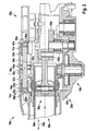
- FIG. 1 shows a hand tool 10a according to the invention with a Schwingungstilgervoriques 12a, a drive mechanism 18a and with a mechanism housing 20a, which has a metallic housing cover 22a.
- the hand tool 10a is designed as a drill and chisel hammer.
- the mechanism housing 20a encloses a space 24a in which the drive mechanism 18a and the vibration absorber device 12a are arranged.
- the hand tool 10a has a main handle 44a, an insert tool attachment 46a, a motor housing 48a, and an auxiliary handle 50a.
- the main handle 44a is connected to the mechanical housing 20a and the motor housing 48a on a side of the mechanical housing 20a facing away from the tool attachment 46a.
- the auxiliary handle 50a is connected to the mechanism housing 20a on a side facing the insert tool attachment 46a.
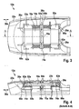
- FIG. 2 shows a section through the mechanism housing 20a, which has a housing shell 52a next to the housing cover 22a.
- the drive mechanism 18a has a striking mechanism 28a, a first and a second transmission element 54a, 56a for a drilling operation and a switching mechanism 58a.
- the hammer mechanism 28a is designed as a hammer blower.
- the first gear element 54a is additionally formed as an eccentric element of the percussion mechanism 28a.
- the striking mechanism 28a has a piston 59a, a hammer tube 60a and, not shown in more detail, a racket and an anvil.
- the second transmission element 56a rotatably drives the hammer tube 60a. The rotational movement of the hammer tube 60a can be switched off by the switching mechanism 58a in a manner which appears appropriate to a person skilled in the art.
- the housing cover 22a of the mechanism housing 20a is arranged on a side of the housing shell 52a opposite the motor housing 48a. It closes a mounting opening located there and thus the space 24a.
- the hand tool 10a has a seal, not shown, which is arranged between the housing cover 22a and the housing shell 52a. As a result, the vibration damper device 12a and the drive mechanism 18a are protected from contamination.
- the space 24a is formed as a grease space, that is, in the room a common, permanent lubrication is ensured.
- the Schwingungstilgervorides 12 a and the drive mechanism 18 a are arranged in the space 24 a, which closes the housing cover 22 a.
- the housing cover 22a on three fastening means 26a The fastening means 26a are formed as integrally formed webs.
- the fastening means 26a have fastening surfaces 62a aligned perpendicular to a spring direction 30a.
- the fasteners 26a attach to the assembly assembly, that is, after the Schwingungstilgervorides 12a has been inserted into the lid, and during operation, the vibration absorber 12a in the spring direction 30a.
- the Schwingungstilgervoruze 12a is compressed in the spring 30a and mounted in the housing cover 22a during assembly.
- idler springs 14a of the vibration absorber device 12a are caused by a bias in the spring direction 30a after assembly and during operation Fixing force on the housing cover 22a.
- the fastening force secures the Schwingungstilgervorides 12 a non-positively perpendicular to the spring direction 30 a on the housing cover 22 a.
- the vibration absorber device 12a and the casing cover 22a form a preassemblable assembly, that is, the vibration absorber device 12a and the casing cover 22a together and separated from the casing shell 52a form a stable unit.
- the housing cover 22a After mounting the housing cover 22a on the housing shell 52a causes the housing shell 52a in a non-illustrated area a fastening force on the Schwingungstilgervorides 12a.
- the fastening force acts perpendicular to the spring direction 30a.
- the Schwingungstilgervorides 12a could be locked to the housing cover 22a, screwed, glued and / or be connected to another, the expert appears reasonable sense manner.
- the percussion mechanism 28a and the vibration absorber device 12a are partially disposed on the same planes that are perpendicular to a spring direction 30a, that is, the percussion mechanism 28a and the vibration absorber device 12a are disposed partially adjacent to each other.
- a region of the vibration damper device 12a facing the insert tool attachment 46a is arranged between the housing cover 22a and the striking mechanism 28a. This area is functional component-free except for the vibration absorber device 12a.
- the Schwingungstilgervorides 12 a is mirror-symmetrical in a stationary state. It has the four Tilgerfedern 14 a, a damping mass 16 a, two holding parts 32 a two spring receptacles 36 a and two spring receiving fasteners 64 a.
- the two holding parts 32a are formed as identical parts, that is, they have a same, but mirrored to each other shape. In addition, the holding parts 32a have a slight oversize relative to the housing cover 22a. Outer sides 66a of the holding parts 32a, which face the insert tool attachment 46a, fasten the vibration absorber device 12a in the housing cover 22a.
- the Tilgerfedern 14 a, the absorber mass 16 a, the two spring receivers 36 a and the two spring receiving fasteners 64 a are arranged between the holding parts 32 a.
- the spring receptacles 36a and the spring receiving fasteners 64a are at least partially made of plastic.
- the holding parts 32a have guide surfaces 68a, which guide the absorber mass 16a in the spring direction 30a during operation.
- the holding parts 32a enclose the absorber mass 16a on a plane that is perpendicular to the spring direction 30a. In this embodiment, the holding parts 32a completely surround the absorber mass 16a.
- the holding parts 32a could enclose the absorber mass 16a by more than 180 degrees.
- the retaining members 32a guide the absorber mass 16a to surfaces furthest from a center of gravity 70a of the absorber mass 16a, whereby low guiding forces and low friction can be achieved.
- a housing cover could also guide the absorber mass 16a and / or the absorber spring 14a.
- the holding parts 32a each have spring attachments 72a, which fix the Tilgerfedern 14a. For this purpose, the Tilgerfedern 14a are screwed onto the spring fasteners 72a.
- the four Tilgerfedern 14a are mechanically fixedly connected on one side with the holding parts 32a and on one side with the spring receivers 36a.
- the spring receptacles 36a have, seen perpendicular to the spring direction 30a, a cross-shaped cross-section on ( FIG. 5 ).
- the spring receivers 36a On a side facing the center of gravity 70a of the absorber mass 16a, the spring receivers 36a extend into recesses 74a of the absorber mass 16a.
- the spring retainers 36a are supported on the absorber mass 16a.
- the Schwingungstilgervoriques 12a may not shown damping elements, which dampen a striking of the absorber mass 16a at an end stop.
- the damping elements between the spring receivers 36a and the holding parts 32a could be arranged in the interior of the Tilgerfedern 14a in a guide of the holding parts 32a or on the housing cover 22a.
- the absorber mass 16a has a homogeneous cross-section in the spring direction 30a.
- the cross section is shaped by a bar pressing method.
- Absorber masses are cut down by a machine from a pole and provided in the same step with recesses for receiving spring mounts.
- an absorber mass could have several parts by mass.
- at least one of the mass parts likewise has a homogeneous cross-section.
- at least one of the mass parts along at least one direction preferably has mostly a standardized cross-section.
- FIGS. 8 to 14 three further embodiments of the invention are shown. To distinguish the embodiments, the letter a in the reference numerals of the embodiment in the FIGS. 1 to 7 by the letters b to d in the reference numerals of the embodiments in the FIGS. 8 to 14 replaced.
- the following descriptions are essentially limited to the differences between the embodiments, with respect to the same components, features and functions on the description of the other embodiments, in particular in the FIGS. 1 to 7 , can be referenced.
- FIGS. 8 to 10 relate, as in the embodiment of FIGS. 1 to 7 described, a hand tool 10b according to the invention with a in the FIGS. 8 to 10 illustrated Schwingungstilgervoriques 12b, a drive mechanism 18b and a mechanism housing 20b with a housing cover 22b and a housing shell 52b.
- the housing cover 22b closes in a ready state, a space 24b, in which the drive mechanism 18b is arranged.
- the housing cover 22b has attachment means 26b which secure the vibration absorber device 12b in an operative state.
- the Schwingungstilgervoriques 12b has four Tilgerfedern 14b, an absorber mass 16b and two holding parts 32b.
- the holding parts 32b are formed as equal parts.
- Each holding part 32b has two spring attachments 72b and two guide means 76b.
- the guide means 76b are formed as rods formed on a base plate 78b of the holding parts 32b.
- the guide means 76b engage in recesses 80b of the absorber mass 16b and guide them in the spring direction 30b.
- guide means 76b could also completely penetrate the absorber mass 16b in the spring direction 30b.
- the absorber mass 16b has a first and a second mass portion 82b, 84b.
- the a percussion 28b facing in the FIG. 9 shown below, first mass portion 82b is about the same weight as the second mass portion 84b.
- a heaviest mass part has at most four times as large mass as a lightest mass part.
- a separation between the two mass parts 82b, 84b is parallel to the spring direction 30b and substantially parallel to a main extension of the absorber mass 16b.
- a separation could also be arranged perpendicular to a main extension of an absorber mass or perpendicular to the spring direction.
- the mass parts are screwed together in the middle.
- the mass parts 82b, 84b on outer sides 86b are clamped together by latching hooks 88b.
- the absorber mass 16b encloses the Tilgerfedern 14b on a plane which is aligned perpendicular to the spring direction 30b by more than 180 Grand, in this embodiment completely. In the enclosed areas, the absorber mass 16b guides the absorber springs 14b.
- FIGS. 11 and 12 relate, as in the embodiment of FIGS. 1 to 7 described, a hand tool 10c invention with a in the FIGS. 11 and 12 illustrated Schwingungstilgervoriques 12c, a drive mechanism 18c and a mechanical housing 20c with a housing cover 22c and a housing shell 52c.
- the housing cover 22c closes in a ready state a space 24c, in which the drive mechanism 18c is arranged.
- the housing cover 22c has attachment means 26c which secure the vibration absorber device 12c in an operative state.
- the vibration absorber 12c has first and second holding parts 32c, 34c.
- the first holding part 32c is arranged facing an insert tool attachment 46c.
- the second holding part 34c is disposed away from the insert tool attachment 46c.
- the first holding part 32c and the second holding part 34c are supported by the Tilgerfedern 14c against each other.
- the two holding parts 32c, 34c each have two rod-shaped projections 90c, 92c.
- the projections 90c of the first holding part 32c penetrate two of the Tilgerfedern 14c. In this case, the projections 90c lead the Tilgerfedern 14c.
- Ends of the projections 90c which faces away from a base plate 78c of the first holding part 32c are movably mounted in a recess or bore of the second holding part 34c.
- the projections 92c of the second holding part 34c penetrate and also guide two of the Tilgerfedern 14c. Ends of the projections 92 c, which are facing away from a base plate 78 c of the second holding part 34 c, penetrate a recess or bore of the first holding part 32 c.
- the projections 92c are latched to the first holding part 32c.
- the vibration absorber 12c has more than two guide rods 90c, 92c that guide the absorber mass 16c.
- FIG. 12 It can be seen that the outer Tilgerfedern 14c are slightly lower, that is arranged closer to the drive mechanism 18c, as the inner Tilgerfedern 14c. In addition, all, that is, the four Tilgerfedern 14c, partially disposed on a plane which is aligned perpendicular to the spring direction 30c. As a result, the Schwingungstilgervorides 12c is particularly space-saving integrated into the housing cover 22c. Furthermore, only one of the two holding parts 32c, 34c is mechanically fixedly connected to the mechanism housing 20c.
- FIGS. 13 and 14 relate, as in the embodiment of FIGS. 1 to 7 described, a hand tool 10d according to the invention with a in the FIGS. 13 and 14 illustrated Schwingungstilgervoriques 12d, a drive mechanism 18d and a mechanism housing 20d with a housing cover 22d and a housing shell 52d.
- the housing cover 22d closes in a ready state, a space 24d, in which the drive mechanism 18d is arranged.
- the housing cover 22d has attachment means 26d which secure the vibration absorber device 12d in an operative state.
- the Schwingungstilgervorides 12d has two Tilgerfedern 14d, an absorber mass 16d, a first and a second holding part 32d, a first and a second spring receiving 36d, 38d and four support members 40d, 42d.
- the holding parts 32d are pushed onto the absorber mass 16d. There, the holding parts 32 d are secured with locking elements 94 d.
- the blocking elements 94d are designed as clamping sleeves, but could also be designed as other units that appear appropriate to the person skilled in the art.
- the holding parts 32d are movably mounted in the spring direction 30d on the absorber mass 16d, in each case between two Locking elements 94d and a center shoulder 96d.
- the center shoulder 96d extends perpendicular to the spring direction 30d.
- the first holding part 32d and the first spring holder 36d are arranged facing the insert tool attachment 46d.
- the absorber mass 16d moves the second spring receiver 38d in the direction of the insert tool attachment 46d.
- the second spring retainer 38d exerts an acceleration force on the absorber mass 16d.
- the acceleration force brakes the absorber mass 16d.
- the second spring receptacle 38d transmits via the blocking elements 94d a kinetic energy of the absorber mass 16d to the Tilgerfedern 14d.
- the Tilgerfedern 14d store this energy between.
- the Tilgerfedern 14d After the Tilgerfedern 14d have the absorber mass 16d stopped relative to the holding parts 32d, the Tilgerfedern 14d give the energy back to the absorber mass 16d, thereby accelerating the absorber mass 16d.
- the first spring receptacle 36d supports a counterforce of the acceleration force on the first holding part 32d. After the absorber mass 16d has crossed a middle position, the same process takes place mirror-inverted in an opposite direction.
- the support members 40d, 42d press in two different operating states, the spring retainers 36d, 38d against the Tilgerfedern 14d.
- the support members 40d, 42d are formed as support springs.
- a force of the support elements 40d, 42d is significantly smaller than the acceleration force of the Tilgerfedern 14d.
- the support elements 40d, 42d are aligned coaxially with the Tilgerfedern 14d.
- the Tilgerfedern 14 d are completely in an axial region, that is arranged laterally next to the absorber mass 16 d.
Landscapes
- Engineering & Computer Science (AREA)
- Mechanical Engineering (AREA)
- Percussive Tools And Related Accessories (AREA)
- Vibration Prevention Devices (AREA)
Applications Claiming Priority (2)
| Application Number | Priority Date | Filing Date | Title |
|---|---|---|---|
| DE102009054723A DE102009054723A1 (de) | 2009-12-16 | 2009-12-16 | Handwerkzeugmaschine |
| PCT/EP2010/065979 WO2011072918A1 (de) | 2009-12-16 | 2010-10-22 | Handwerkzeugmaschine mit einer schwingungstilgervorrichtung |
Publications (2)
| Publication Number | Publication Date |
|---|---|
| EP2512751A1 EP2512751A1 (de) | 2012-10-24 |
| EP2512751B1 true EP2512751B1 (de) | 2015-10-14 |
Family
ID=43416962
Family Applications (1)
| Application Number | Title | Priority Date | Filing Date |
|---|---|---|---|
| EP10778898.6A Active EP2512751B1 (de) | 2009-12-16 | 2010-10-22 | Handwerkzeugmaschine mit einer schwingungstilgervorrichtung |
Country Status (6)
| Country | Link |
|---|---|
| US (1) | US9358677B2 (ja) |
| EP (1) | EP2512751B1 (ja) |
| JP (1) | JP5542960B2 (ja) |
| CN (1) | CN102741018B (ja) |
| DE (1) | DE102009054723A1 (ja) |
| WO (1) | WO2011072918A1 (ja) |
Families Citing this family (15)
| Publication number | Priority date | Publication date | Assignee | Title |
|---|---|---|---|---|
| CN102554892A (zh) * | 2012-01-15 | 2012-07-11 | 胡继宁 | 具有减振装置的摆式动力工具 |
| JP2013193186A (ja) * | 2012-03-22 | 2013-09-30 | Hitachi Koki Co Ltd | 電動工具 |
| JP5870888B2 (ja) * | 2012-09-28 | 2016-03-01 | 日立工機株式会社 | 打撃工具 |
| JP6271577B2 (ja) * | 2012-12-17 | 2018-01-31 | スウェレア・アイブイエフ・エービーSwerea IVF AB | 衝撃マシン |
| US10232500B2 (en) | 2012-12-17 | 2019-03-19 | Swerea Ivf Ab | Impact machine |
| US9950418B2 (en) * | 2012-12-25 | 2018-04-24 | Makita Corporation | Impact tool |
| US10131042B2 (en) | 2013-10-21 | 2018-11-20 | Milwaukee Electric Tool Corporation | Adapter for power tool devices |
| AU2015276285A1 (en) * | 2014-06-16 | 2017-01-19 | Swerea Ivf Ab | An impact machine |
| DE102015205149A1 (de) * | 2015-03-23 | 2016-09-29 | Robert Bosch Gmbh | Handwerkzeugmaschine |
| JP6863704B2 (ja) | 2016-10-07 | 2021-04-21 | 株式会社マキタ | 打撃工具 |
| US10875168B2 (en) | 2016-10-07 | 2020-12-29 | Makita Corporation | Power tool |
| US11571796B2 (en) * | 2018-04-04 | 2023-02-07 | Milwaukee Electric Tool Corporation | Rotary hammer |
| JP7246202B2 (ja) | 2019-02-19 | 2023-03-27 | 株式会社マキタ | 震動機構付き電動工具 |
| JP7229807B2 (ja) | 2019-02-21 | 2023-02-28 | 株式会社マキタ | 電動工具 |
| US11642769B2 (en) * | 2021-02-22 | 2023-05-09 | Makita Corporation | Power tool having a hammer mechanism |
Family Cites Families (25)
| Publication number | Priority date | Publication date | Assignee | Title |
|---|---|---|---|---|
| JPS5824235B2 (ja) * | 1976-03-12 | 1983-05-19 | 日立工機株式会社 | 携帯用工具における防振装置 |
| DE3122979A1 (de) * | 1981-06-10 | 1983-01-05 | Hilti AG, 9494 Schaan | Bohr- oder meisselhammer |
| JP4195818B2 (ja) * | 2003-01-16 | 2008-12-17 | 株式会社マキタ | 電動ハンマ |
| EP1464449B1 (en) * | 2003-04-01 | 2010-03-24 | Makita Corporation | Power tool |
| JP4276095B2 (ja) * | 2004-01-26 | 2009-06-10 | 株式会社マキタ | 作業工具 |
| JP4509698B2 (ja) * | 2004-08-27 | 2010-07-21 | 株式会社マキタ | 作業工具 |
| JP4647957B2 (ja) * | 2004-08-27 | 2011-03-09 | 株式会社マキタ | 作業工具 |
| GB2429675A (en) * | 2005-06-23 | 2007-03-07 | Black & Decker Inc | Vibration dampening mechanism |
| US7469752B2 (en) | 2005-12-02 | 2008-12-30 | Makita Corporation | Power tool |
| MX2008010882A (es) * | 2006-03-07 | 2008-09-04 | Hitachi Koki Kk | Herramienta de energia electrica. |
| JP5041575B2 (ja) * | 2006-03-07 | 2012-10-03 | 日立工機株式会社 | 打撃工具 |
| DE102007000057B4 (de) * | 2007-01-31 | 2010-07-08 | Hilti Aktiengesellschaft | Schwingungstilger für Handwerkzeugmaschine |
| DE102007000059A1 (de) * | 2007-01-31 | 2008-09-18 | Hilti Aktiengesellschaft | Handwerkzeugmaschine mit Schwingungstilger |
| BRPI0808724A2 (pt) * | 2007-05-01 | 2015-11-24 | Hitachi Koki Kk | ferramentas de movimento de vaivém |
| JP5376194B2 (ja) * | 2007-08-27 | 2013-12-25 | 日立工機株式会社 | 往復動工具 |
| US7832498B2 (en) * | 2007-06-15 | 2010-11-16 | Makita Corporation | Impact tool |
| JP5147449B2 (ja) | 2007-07-24 | 2013-02-20 | 株式会社マキタ | 作業工具 |
| US7806201B2 (en) * | 2007-07-24 | 2010-10-05 | Makita Corporation | Power tool with dynamic vibration damping |
| DE102007000837A1 (de) * | 2007-10-09 | 2009-04-16 | Hilti Aktiengesellschaft | Handwerkzeugmaschine mit Schwingungsausgleichsmasse |
| US8196674B2 (en) | 2008-03-05 | 2012-06-12 | Makita Corporation | Impact tool |
| JP5202997B2 (ja) | 2008-03-05 | 2013-06-05 | 株式会社マキタ | 作業工具 |
| DE102008000625A1 (de) * | 2008-03-12 | 2009-09-17 | Robert Bosch Gmbh | Handwerkzeugmaschine |
| JP5128998B2 (ja) | 2008-04-04 | 2013-01-23 | 株式会社マキタ | 手持式作業工具 |
| JP5269566B2 (ja) * | 2008-12-03 | 2013-08-21 | 株式会社マキタ | 作業工具 |
| DE102009054728A1 (de) * | 2009-12-16 | 2011-06-22 | Robert Bosch GmbH, 70469 | Handwerkzeugmaschine |
-
2009
- 2009-12-16 DE DE102009054723A patent/DE102009054723A1/de not_active Withdrawn
-
2010
- 2010-10-22 CN CN201080057001.XA patent/CN102741018B/zh active Active
- 2010-10-22 JP JP2012543545A patent/JP5542960B2/ja active Active
- 2010-10-22 US US13/515,788 patent/US9358677B2/en active Active
- 2010-10-22 EP EP10778898.6A patent/EP2512751B1/de active Active
- 2010-10-22 WO PCT/EP2010/065979 patent/WO2011072918A1/de active Application Filing
Also Published As
| Publication number | Publication date |
|---|---|
| US9358677B2 (en) | 2016-06-07 |
| JP2013514195A (ja) | 2013-04-25 |
| WO2011072918A1 (de) | 2011-06-23 |
| CN102741018B (zh) | 2015-11-25 |
| CN102741018A (zh) | 2012-10-17 |
| EP2512751A1 (de) | 2012-10-24 |
| JP5542960B2 (ja) | 2014-07-09 |
| DE102009054723A1 (de) | 2011-06-22 |
| US20120318551A1 (en) | 2012-12-20 |
Similar Documents
| Publication | Publication Date | Title |
|---|---|---|
| EP2512751B1 (de) | Handwerkzeugmaschine mit einer schwingungstilgervorrichtung | |
| EP2512750B1 (de) | Handwerkzeugmaschine mit einer schwingungstilgervorrichtung | |
| EP2190630B1 (de) | Handwerkzeugmaschine mit einem durch ein ausgleichsmittel schwingungsgedämpften handgriff | |
| DE102006000375A1 (de) | Handwerkzeuggerät mit Entkoppelungsanordnung | |
| EP1202840A1 (de) | Bohr- oder schlaghammer | |
| EP3638457B1 (de) | Handwerkzeugmaschine | |
| DE102009054728A1 (de) | Handwerkzeugmaschine | |
| EP1849561B1 (de) | Handwerkzeuggerät mit verstellbaren Handgriffen | |
| DE10236135B4 (de) | Tragbares, handgeführtes Werkzeug | |
| EP2560794B1 (de) | Handwerkzeugmaschinenvorrichtung | |
| EP2822734B1 (de) | Handwerkzeugmaschinenvorrichtung | |
| EP2750836B1 (de) | Handgriffvorrichtung | |
| EP3274132B1 (de) | Handwerkzeugmaschine | |
| EP2283978A2 (de) | Handwerkzeugmaschinenvorrichtung | |
| DE102008000937A1 (de) | Elektrohandwerkzeug mit Flachdrahtwellenfeder | |
| EP2512749B1 (de) | Handwerkzeugmaschinenvorrichtung | |
| EP4331774A1 (de) | Werkzeugmaschine mit einer entkopplungsvorrichtung | |
| WO2012045504A1 (de) | Mehrdimensionaler schwingungstilger | |
| WO2013131678A1 (de) | Handwerkzeugmaschinenvorrichtung | |
| EP4331775A1 (de) | Werkzeugmaschine mit einer abschotteinrichtung | |
| DE102007062719A1 (de) | Zusatzhandgriffvorrichtung | |
| DE102015204843A1 (de) | Dämpfungsvorrichtung für eine Handwerkzeugmaschine |
Legal Events
| Date | Code | Title | Description |
|---|---|---|---|
| PUAI | Public reference made under article 153(3) epc to a published international application that has entered the european phase |
Free format text: ORIGINAL CODE: 0009012 |
|
| 17P | Request for examination filed |
Effective date: 20120716 |
|
| AK | Designated contracting states |
Kind code of ref document: A1 Designated state(s): AL AT BE BG CH CY CZ DE DK EE ES FI FR GB GR HR HU IE IS IT LI LT LU LV MC MK MT NL NO PL PT RO RS SE SI SK SM TR |
|
| DAX | Request for extension of the european patent (deleted) | ||
| GRAP | Despatch of communication of intention to grant a patent |
Free format text: ORIGINAL CODE: EPIDOSNIGR1 |
|
| INTG | Intention to grant announced |
Effective date: 20150715 |
|
| GRAS | Grant fee paid |
Free format text: ORIGINAL CODE: EPIDOSNIGR3 |
|
| GRAA | (expected) grant |
Free format text: ORIGINAL CODE: 0009210 |
|
| AK | Designated contracting states |
Kind code of ref document: B1 Designated state(s): AL AT BE BG CH CY CZ DE DK EE ES FI FR GB GR HR HU IE IS IT LI LT LU LV MC MK MT NL NO PL PT RO RS SE SI SK SM TR |
|
| REG | Reference to a national code |
Ref country code: GB Ref legal event code: FG4D Free format text: NOT ENGLISH |
|
| REG | Reference to a national code |
Ref country code: AT Ref legal event code: REF Ref document number: 754754 Country of ref document: AT Kind code of ref document: T Effective date: 20151015 Ref country code: CH Ref legal event code: EP |
|
| REG | Reference to a national code |
Ref country code: IE Ref legal event code: FG4D Free format text: LANGUAGE OF EP DOCUMENT: GERMAN |
|
| REG | Reference to a national code |
Ref country code: DE Ref legal event code: R096 Ref document number: 502010010476 Country of ref document: DE |
|
| REG | Reference to a national code |
Ref country code: FR Ref legal event code: PLFP Year of fee payment: 6 |
|
| REG | Reference to a national code |
Ref country code: NL Ref legal event code: MP Effective date: 20151014 |
|
| REG | Reference to a national code |
Ref country code: LT Ref legal event code: MG4D |
|
| PG25 | Lapsed in a contracting state [announced via postgrant information from national office to epo] |
Ref country code: LT Free format text: LAPSE BECAUSE OF FAILURE TO SUBMIT A TRANSLATION OF THE DESCRIPTION OR TO PAY THE FEE WITHIN THE PRESCRIBED TIME-LIMIT Effective date: 20151014 Ref country code: IS Free format text: LAPSE BECAUSE OF FAILURE TO SUBMIT A TRANSLATION OF THE DESCRIPTION OR TO PAY THE FEE WITHIN THE PRESCRIBED TIME-LIMIT Effective date: 20160214 Ref country code: IT Free format text: LAPSE BECAUSE OF FAILURE TO SUBMIT A TRANSLATION OF THE DESCRIPTION OR TO PAY THE FEE WITHIN THE PRESCRIBED TIME-LIMIT Effective date: 20151014 Ref country code: ES Free format text: LAPSE BECAUSE OF FAILURE TO SUBMIT A TRANSLATION OF THE DESCRIPTION OR TO PAY THE FEE WITHIN THE PRESCRIBED TIME-LIMIT Effective date: 20151014 Ref country code: NO Free format text: LAPSE BECAUSE OF FAILURE TO SUBMIT A TRANSLATION OF THE DESCRIPTION OR TO PAY THE FEE WITHIN THE PRESCRIBED TIME-LIMIT Effective date: 20160114 Ref country code: NL Free format text: LAPSE BECAUSE OF FAILURE TO SUBMIT A TRANSLATION OF THE DESCRIPTION OR TO PAY THE FEE WITHIN THE PRESCRIBED TIME-LIMIT Effective date: 20151014 Ref country code: HR Free format text: LAPSE BECAUSE OF FAILURE TO SUBMIT A TRANSLATION OF THE DESCRIPTION OR TO PAY THE FEE WITHIN THE PRESCRIBED TIME-LIMIT Effective date: 20151014 |
|
| PG25 | Lapsed in a contracting state [announced via postgrant information from national office to epo] |
Ref country code: PT Free format text: LAPSE BECAUSE OF FAILURE TO SUBMIT A TRANSLATION OF THE DESCRIPTION OR TO PAY THE FEE WITHIN THE PRESCRIBED TIME-LIMIT Effective date: 20160215 Ref country code: RS Free format text: LAPSE BECAUSE OF FAILURE TO SUBMIT A TRANSLATION OF THE DESCRIPTION OR TO PAY THE FEE WITHIN THE PRESCRIBED TIME-LIMIT Effective date: 20151014 Ref country code: SE Free format text: LAPSE BECAUSE OF FAILURE TO SUBMIT A TRANSLATION OF THE DESCRIPTION OR TO PAY THE FEE WITHIN THE PRESCRIBED TIME-LIMIT Effective date: 20151014 Ref country code: LV Free format text: LAPSE BECAUSE OF FAILURE TO SUBMIT A TRANSLATION OF THE DESCRIPTION OR TO PAY THE FEE WITHIN THE PRESCRIBED TIME-LIMIT Effective date: 20151014 Ref country code: GR Free format text: LAPSE BECAUSE OF FAILURE TO SUBMIT A TRANSLATION OF THE DESCRIPTION OR TO PAY THE FEE WITHIN THE PRESCRIBED TIME-LIMIT Effective date: 20160115 Ref country code: PL Free format text: LAPSE BECAUSE OF FAILURE TO SUBMIT A TRANSLATION OF THE DESCRIPTION OR TO PAY THE FEE WITHIN THE PRESCRIBED TIME-LIMIT Effective date: 20151014 Ref country code: FI Free format text: LAPSE BECAUSE OF FAILURE TO SUBMIT A TRANSLATION OF THE DESCRIPTION OR TO PAY THE FEE WITHIN THE PRESCRIBED TIME-LIMIT Effective date: 20151014 |
|
| REG | Reference to a national code |
Ref country code: DE Ref legal event code: R097 Ref document number: 502010010476 Country of ref document: DE |
|
| REG | Reference to a national code |
Ref country code: IE Ref legal event code: MM4A |
|
| PG25 | Lapsed in a contracting state [announced via postgrant information from national office to epo] |
Ref country code: MC Free format text: LAPSE BECAUSE OF FAILURE TO SUBMIT A TRANSLATION OF THE DESCRIPTION OR TO PAY THE FEE WITHIN THE PRESCRIBED TIME-LIMIT Effective date: 20151014 Ref country code: CZ Free format text: LAPSE BECAUSE OF FAILURE TO SUBMIT A TRANSLATION OF THE DESCRIPTION OR TO PAY THE FEE WITHIN THE PRESCRIBED TIME-LIMIT Effective date: 20151014 |
|
| PLBE | No opposition filed within time limit |
Free format text: ORIGINAL CODE: 0009261 |
|
| STAA | Information on the status of an ep patent application or granted ep patent |
Free format text: STATUS: NO OPPOSITION FILED WITHIN TIME LIMIT |
|
| PG25 | Lapsed in a contracting state [announced via postgrant information from national office to epo] |
Ref country code: RO Free format text: LAPSE BECAUSE OF FAILURE TO SUBMIT A TRANSLATION OF THE DESCRIPTION OR TO PAY THE FEE WITHIN THE PRESCRIBED TIME-LIMIT Effective date: 20151014 Ref country code: SM Free format text: LAPSE BECAUSE OF FAILURE TO SUBMIT A TRANSLATION OF THE DESCRIPTION OR TO PAY THE FEE WITHIN THE PRESCRIBED TIME-LIMIT Effective date: 20151014 Ref country code: SK Free format text: LAPSE BECAUSE OF FAILURE TO SUBMIT A TRANSLATION OF THE DESCRIPTION OR TO PAY THE FEE WITHIN THE PRESCRIBED TIME-LIMIT Effective date: 20151014 Ref country code: EE Free format text: LAPSE BECAUSE OF FAILURE TO SUBMIT A TRANSLATION OF THE DESCRIPTION OR TO PAY THE FEE WITHIN THE PRESCRIBED TIME-LIMIT Effective date: 20151014 Ref country code: DK Free format text: LAPSE BECAUSE OF FAILURE TO SUBMIT A TRANSLATION OF THE DESCRIPTION OR TO PAY THE FEE WITHIN THE PRESCRIBED TIME-LIMIT Effective date: 20151014 |
|
| 26N | No opposition filed |
Effective date: 20160715 |
|
| REG | Reference to a national code |
Ref country code: FR Ref legal event code: PLFP Year of fee payment: 7 |
|
| PG25 | Lapsed in a contracting state [announced via postgrant information from national office to epo] |
Ref country code: IE Free format text: LAPSE BECAUSE OF NON-PAYMENT OF DUE FEES Effective date: 20151022 |
|
| PG25 | Lapsed in a contracting state [announced via postgrant information from national office to epo] |
Ref country code: SI Free format text: LAPSE BECAUSE OF FAILURE TO SUBMIT A TRANSLATION OF THE DESCRIPTION OR TO PAY THE FEE WITHIN THE PRESCRIBED TIME-LIMIT Effective date: 20151014 |
|
| REG | Reference to a national code |
Ref country code: AT Ref legal event code: MM01 Ref document number: 754754 Country of ref document: AT Kind code of ref document: T Effective date: 20151022 |
|
| PG25 | Lapsed in a contracting state [announced via postgrant information from national office to epo] |
Ref country code: AT Free format text: LAPSE BECAUSE OF NON-PAYMENT OF DUE FEES Effective date: 20151022 |
|
| PG25 | Lapsed in a contracting state [announced via postgrant information from national office to epo] |
Ref country code: HU Free format text: LAPSE BECAUSE OF FAILURE TO SUBMIT A TRANSLATION OF THE DESCRIPTION OR TO PAY THE FEE WITHIN THE PRESCRIBED TIME-LIMIT; INVALID AB INITIO Effective date: 20101022 Ref country code: BG Free format text: LAPSE BECAUSE OF FAILURE TO SUBMIT A TRANSLATION OF THE DESCRIPTION OR TO PAY THE FEE WITHIN THE PRESCRIBED TIME-LIMIT Effective date: 20151014 |
|
| PG25 | Lapsed in a contracting state [announced via postgrant information from national office to epo] |
Ref country code: CY Free format text: LAPSE BECAUSE OF FAILURE TO SUBMIT A TRANSLATION OF THE DESCRIPTION OR TO PAY THE FEE WITHIN THE PRESCRIBED TIME-LIMIT Effective date: 20151014 |
|
| PG25 | Lapsed in a contracting state [announced via postgrant information from national office to epo] |
Ref country code: BE Free format text: LAPSE BECAUSE OF NON-PAYMENT OF DUE FEES Effective date: 20151031 |
|
| PG25 | Lapsed in a contracting state [announced via postgrant information from national office to epo] |
Ref country code: MT Free format text: LAPSE BECAUSE OF FAILURE TO SUBMIT A TRANSLATION OF THE DESCRIPTION OR TO PAY THE FEE WITHIN THE PRESCRIBED TIME-LIMIT Effective date: 20151014 |
|
| REG | Reference to a national code |
Ref country code: FR Ref legal event code: PLFP Year of fee payment: 8 |
|
| PG25 | Lapsed in a contracting state [announced via postgrant information from national office to epo] |
Ref country code: LU Free format text: LAPSE BECAUSE OF NON-PAYMENT OF DUE FEES Effective date: 20151022 |
|
| PG25 | Lapsed in a contracting state [announced via postgrant information from national office to epo] |
Ref country code: TR Free format text: LAPSE BECAUSE OF FAILURE TO SUBMIT A TRANSLATION OF THE DESCRIPTION OR TO PAY THE FEE WITHIN THE PRESCRIBED TIME-LIMIT Effective date: 20151014 Ref country code: MK Free format text: LAPSE BECAUSE OF FAILURE TO SUBMIT A TRANSLATION OF THE DESCRIPTION OR TO PAY THE FEE WITHIN THE PRESCRIBED TIME-LIMIT Effective date: 20151014 |
|
| REG | Reference to a national code |
Ref country code: FR Ref legal event code: PLFP Year of fee payment: 9 |
|
| PG25 | Lapsed in a contracting state [announced via postgrant information from national office to epo] |
Ref country code: AL Free format text: LAPSE BECAUSE OF FAILURE TO SUBMIT A TRANSLATION OF THE DESCRIPTION OR TO PAY THE FEE WITHIN THE PRESCRIBED TIME-LIMIT Effective date: 20151014 |
|
| PGFP | Annual fee paid to national office [announced via postgrant information from national office to epo] |
Ref country code: CH Payment date: 20191023 Year of fee payment: 10 |
|
| REG | Reference to a national code |
Ref country code: CH Ref legal event code: PL |
|
| PG25 | Lapsed in a contracting state [announced via postgrant information from national office to epo] |
Ref country code: LI Free format text: LAPSE BECAUSE OF NON-PAYMENT OF DUE FEES Effective date: 20201031 Ref country code: CH Free format text: LAPSE BECAUSE OF NON-PAYMENT OF DUE FEES Effective date: 20201031 |
|
| PGFP | Annual fee paid to national office [announced via postgrant information from national office to epo] |
Ref country code: GB Payment date: 20231025 Year of fee payment: 14 |
|
| PGFP | Annual fee paid to national office [announced via postgrant information from national office to epo] |
Ref country code: FR Payment date: 20231023 Year of fee payment: 14 |
|
| PGFP | Annual fee paid to national office [announced via postgrant information from national office to epo] |
Ref country code: DE Payment date: 20231218 Year of fee payment: 14 |