EP3638457B1 - Handwerkzeugmaschine - Google Patents
Handwerkzeugmaschine Download PDFInfo
- Publication number
- EP3638457B1 EP3638457B1 EP18729382.4A EP18729382A EP3638457B1 EP 3638457 B1 EP3638457 B1 EP 3638457B1 EP 18729382 A EP18729382 A EP 18729382A EP 3638457 B1 EP3638457 B1 EP 3638457B1
- Authority
- EP
- European Patent Office
- Prior art keywords
- hand
- held power
- power tool
- tool
- designed
- Prior art date
- Legal status (The legal status is an assumption and is not a legal conclusion. Google has not performed a legal analysis and makes no representation as to the accuracy of the status listed.)
- Active
Links
Images


Classifications
-
- B—PERFORMING OPERATIONS; TRANSPORTING
- B25—HAND TOOLS; PORTABLE POWER-DRIVEN TOOLS; MANIPULATORS
- B25D—PERCUSSIVE TOOLS
- B25D11/00—Portable percussive tools with electromotor or other motor drive
- B25D11/005—Arrangements for adjusting the stroke of the impulse member or for stopping the impact action when the tool is lifted from the working surface
-
- B—PERFORMING OPERATIONS; TRANSPORTING
- B25—HAND TOOLS; PORTABLE POWER-DRIVEN TOOLS; MANIPULATORS
- B25F—COMBINATION OR MULTI-PURPOSE TOOLS NOT OTHERWISE PROVIDED FOR; DETAILS OR COMPONENTS OF PORTABLE POWER-DRIVEN TOOLS NOT PARTICULARLY RELATED TO THE OPERATIONS PERFORMED AND NOT OTHERWISE PROVIDED FOR
- B25F5/00—Details or components of portable power-driven tools not particularly related to the operations performed and not otherwise provided for
- B25F5/001—Gearings, speed selectors, clutches or the like specially adapted for rotary tools
-
- B—PERFORMING OPERATIONS; TRANSPORTING
- B25—HAND TOOLS; PORTABLE POWER-DRIVEN TOOLS; MANIPULATORS
- B25D—PERCUSSIVE TOOLS
- B25D11/00—Portable percussive tools with electromotor or other motor drive
- B25D11/06—Means for driving the impulse member
- B25D11/12—Means for driving the impulse member comprising a crank mechanism
- B25D11/125—Means for driving the impulse member comprising a crank mechanism with a fluid cushion between the crank drive and the striking body
-
- B—PERFORMING OPERATIONS; TRANSPORTING
- B25—HAND TOOLS; PORTABLE POWER-DRIVEN TOOLS; MANIPULATORS
- B25D—PERCUSSIVE TOOLS
- B25D16/00—Portable percussive machines with superimposed rotation, the rotational movement of the output shaft of a motor being modified to generate axial impacts on the tool bit
- B25D16/006—Mode changers; Mechanisms connected thereto
-
- B—PERFORMING OPERATIONS; TRANSPORTING
- B25—HAND TOOLS; PORTABLE POWER-DRIVEN TOOLS; MANIPULATORS
- B25D—PERCUSSIVE TOOLS
- B25D17/00—Details of, or accessories for, portable power-driven percussive tools
- B25D17/04—Handles; Handle mountings
- B25D17/043—Handles resiliently mounted relative to the hammer housing
-
- B—PERFORMING OPERATIONS; TRANSPORTING
- B25—HAND TOOLS; PORTABLE POWER-DRIVEN TOOLS; MANIPULATORS
- B25D—PERCUSSIVE TOOLS
- B25D17/00—Details of, or accessories for, portable power-driven percussive tools
- B25D17/08—Means for retaining and guiding the tool bit, e.g. chucks allowing axial oscillation of the tool bit
- B25D17/084—Rotating chucks or sockets
-
- B—PERFORMING OPERATIONS; TRANSPORTING
- B25—HAND TOOLS; PORTABLE POWER-DRIVEN TOOLS; MANIPULATORS
- B25D—PERCUSSIVE TOOLS
- B25D2211/00—Details of portable percussive tools with electromotor or other motor drive
- B25D2211/003—Crossed drill and motor spindles
-
- B—PERFORMING OPERATIONS; TRANSPORTING
- B25—HAND TOOLS; PORTABLE POWER-DRIVEN TOOLS; MANIPULATORS
- B25D—PERCUSSIVE TOOLS
- B25D2216/00—Details of portable percussive machines with superimposed rotation, the rotational movement of the output shaft of a motor being modified to generate axial impacts on the tool bit
- B25D2216/0084—Mode-changing mechanisms
-
- B—PERFORMING OPERATIONS; TRANSPORTING
- B25—HAND TOOLS; PORTABLE POWER-DRIVEN TOOLS; MANIPULATORS
- B25D—PERCUSSIVE TOOLS
- B25D2217/00—Details of, or accessories for, portable power-driven percussive tools
- B25D2217/0011—Details of anvils, guide-sleeves or pistons
- B25D2217/0019—Guide-sleeves
-
- B—PERFORMING OPERATIONS; TRANSPORTING
- B25—HAND TOOLS; PORTABLE POWER-DRIVEN TOOLS; MANIPULATORS
- B25D—PERCUSSIVE TOOLS
- B25D2250/00—General details of portable percussive tools; Components used in portable percussive tools
- B25D2250/131—Idling mode of tools
-
- B—PERFORMING OPERATIONS; TRANSPORTING
- B25—HAND TOOLS; PORTABLE POWER-DRIVEN TOOLS; MANIPULATORS
- B25D—PERCUSSIVE TOOLS
- B25D2250/00—General details of portable percussive tools; Components used in portable percussive tools
- B25D2250/165—Overload clutches, torque limiters
-
- B—PERFORMING OPERATIONS; TRANSPORTING
- B25—HAND TOOLS; PORTABLE POWER-DRIVEN TOOLS; MANIPULATORS
- B25D—PERCUSSIVE TOOLS
- B25D2250/00—General details of portable percussive tools; Components used in portable percussive tools
- B25D2250/275—Tools having at least two similar components
Definitions
- Rotary hammers with eccentric impact mechanisms of different performance classes are already known both as cordless devices and as mains devices.
- the invention relates to a system consisting of a first hand-held power tool and a second hand-held power tool, each with a percussion mechanism, each with a motor, each with a gearbox comprising the percussion mechanism, which is designed to transmit a drive movement of the motor to an insert tool held in a tool holder, wherein the respective gears have a guide tube that is identical in some areas along a working axis, in which a beater is mounted in an axially movable manner, the guide tube being rotatably coupled to the motor via a first gear unit and the beater being able to be driven in a linear oscillating manner via a piston of a second gear unit.
- the hand-held power tool is designed in particular to drive an insert tool rotating and/or striking along a working axis.
- the working axis extends essentially along the longitudinal extent of the first or second hand-held power tool.
- the insert tool can be designed, for example, as a drill or chisel.
- the insert tool is a wearing part that can be detachably fastened in the tool holder.
- the insert tool has an insertion end that is received in the tool holder of the hand-held power tool.
- the insertion ends of insert tools usually have a standardized shaft diameter that is designed for different device classes or device sizes, for example a 10 mm shaft diameter for SDS-plus tool holders and an 18 mm shaft diameter for SDS-Max tool holders.
- the tool holder preferably includes an interchangeable drill chuck or a fixed drill chuck.
- a “guide tube that is identical in some areas along a working axis” is to be understood in particular as meaning a guide tube which is identical to another guide tube at least to 33%, preferably at least 50%, in particular at least 66% of the length of the guide tube along the longitudinal extent of the hand-held power tool.
- the inside and/or outside diameter of the guide tube of the first hand-held power tool and the second hand-held power tool is identical at least in regions along the working axis.
- the guide tube of the first and/or the second hand-held power tool can be designed in one piece or in several parts.
- the guide tube of the first hand-held power tool and the second hand-held power tool is identical in a region between the rear end, which faces away from the tool holder, and a control opening or the B-impact damping system.
- a ratio between a diameter of the tool holder and a diameter of the guide tube is 1.8 times larger in the first hand-held power tool than in the second hand-held power tool.
- a “diameter of the tool holder” is intended to mean, in particular, an inner diameter of the tool holder that is adapted to the shaft size of the insert tool.
- a “diameter of the guide tube” should be understood to mean in particular the inner diameter of the guide tube.
- a single impact energy of the second hand-held power tool is mechanically reduced in comparison to a single impact energy of the first hand-held power tool. This advantageously allows the second hand-held power tool to be easily adapted to a different area of application.
- Single impact energy is to be understood in particular as meaning the energy that is transferred to the striker during operation of the hand-held power tool or that is transferred from the striker to the insert tool.
- Mechanismically reduced should be understood in particular to mean that the individual impact energy is reduced by the transmission, preferably by the second transmission unit of the transmission.
- the individual impact energy of the second hand-held power tool is preferably reduced by at least 10%, in particular at least 17.5%, preferably by at least 25%.
- the impact power of the second hand-held power tool is mechanically reduced in comparison to an impact power of the first hand-held power tool.
- the impact frequency of the impact mechanism of the first hand-held power tool is essentially identical to the impact frequency of the second hand-held power tool.
- crank stroke of the second gear unit of the second hand-held power tool is reduced, in particular reduced by 10%, preferably reduced by 15%, preferably reduced by 20%, in comparison to a crank stroke of the second gear unit of the first hand-held power tool.
- a crank stroke is to be understood in particular as the axial distance between the two reversal points of the piston in the guide tube. In particular, no axial force acts on the piston at the two reversal points.
- the pistons of the first and second hand-held power tools are each driven via an eccentric unit, with an eccentricity of the eccentric unit of the second hand-held power tool is smaller than an eccentricity of the eccentric unit of the first hand tool.
- the eccentric unit is assigned to the second gear unit.
- the eccentric unit is driven around an axis of rotation by the motor.
- the eccentric unit has a translation element designed as an eccentric pin, which is connected to the piston via a crank element.
- the translation element moves around the axis of rotation on a particularly circular path.
- the eccentricity of the eccentric unit results from the distance between the axis of rotation of the eccentric unit and the path on which the translation element moves.
- an air spring length of the impact mechanism of the first hand-held power tool differs from an air spring length of the impact mechanism of the second hand-held power tool, and is in particular larger.
- the individual impact energy can be reduced in a structurally simple manner by reducing the air spring length of the striking mechanism.
- An air spring length of the striking mechanism should be understood in particular as a minimum distance between the striker and the piston or a distance between the striker and the piston at the front reversal point facing the tool holder.
- the air spring length can be adjusted, for example, via the shape of the racket, the shape of the piston or the shape of the crank element.
- a bearing distance of the striking mechanism of the first hand-held power tool is equal to a bearing clearance of the striking mechanism of the second hand-held power tool.
- a bearing distance is to be understood in particular as a distance between two areas over which the guide tube of the impact mechanism is mounted.
- the bearing distance is a distance between an axial or radial bearing and another axial or radial bearing, each of which supports the guide tube.
- the bearing distance is preferably designed as a distance between two radial bearings.
- a striking point of the first hand-held power tool is equal to a striking point of the second hand-held power tool.
- a hitting point should in particular be the position of the bat, in particular of the rear end of the striker, facing away from the tool holder, in the guide tube, while the insert tool is pressed against the processing surface.
- both the impact point and the air spring length of the first hand-held power tool are identical to the impact point and the air spring length of the second hand-held power tool.
- the first and second hand-held power tools each have a B-impact damping system, which are designed identically to one another.
- a B-impact damping system is intended to mean, in particular, an arrangement of components in the striking mechanism that are designed to dampen the recoil of the insert tool against the direction of impact.
- the bat transfers its energy to the insert tool via a bolt element.
- the B-impact damping system is at least partially arranged in the guide tube and comprises at least one damping element, which can be arranged inside and/or outside the guide tube.
- the mass ratio between the bolt element and the striker in the first hand-held power tool is identical to the second hand-held power tool, so that the same B-impact damping system can advantageously be optimized for both the first and the second hand-held power tool.
- the first and the second hand-held power tool each have a gear housing, with the mechanical components within the gear housing being at least 80%, in particular at least 90%, identical.
- the transmission housing can be designed as an outer housing and/or as an internal housing.
- a diameter of the tool holder of the second hand-held power tool is less than 18 mm, in particular 10 mm, and that the ratio between a diameter of the guide tube and the diameter of the tool holder of the second hand-held power tool is in a range between 2.8 and 3.4 , in particular in a range between 2.9 and 3.1. This can advantageously be used to realize a particularly powerful hand-held power tool.
- the hand-held machine tools are designed to include as many of the same components as possible in order to cost-effectively cover different areas of application.
- the same components and the same structural units are given the same reference numbers below.
- the different variants of the hand-held power tool are identified by the number of apostrophes after the reference number.
- Different embodiments of components or units that are assigned to one or more specific variants of the hand-held power tool are also marked with the same number of apostrophes.
- Alternative embodiments of the components or structural units, which are fundamentally suitable for at least two variants, are identified with a letter after the reference number.
- the first hand tool 10 (see Fig. 1 ) and the second hand tool 10 '(see Fig. 2 ) are designed as cordless handheld power tools.
- the two hand-held power tools 10, 10' each have a tool holder 12, 12' which differ from one another in their diameter 14, 14'.
- the tool holder 12 is designed as a fixed drill chuck and the tool holder 12 'is designed as an interchangeable drill chuck.
- the first hand-held power tool 10 is designed with an SDS-max tool holder 12 and the second hand-held power tool 10' is designed with an SDS-plus tool holder 12'.
- the diameter 14 of the SDS-max tool holder 12 is essentially 18 mm and the diameter 14 'of the SDS-plus tool holder 12' is essentially 10 mm, which results in a ratio between the diameter 14 of the tool holder 12 of the first hand-held power tool 10 and the diameter 14 'of the tool holder 12' of the second hand tool 10' of 1.8 results.
- the third hand tool 10" (see Fig. 9c ) and the fourth hand tool 10′′′ (see Fig. 9d ) are each designed as network handheld machine tools with an SDS-max tool holder 12 and an SDS-plus tool holder 12 '.
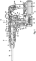
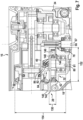
- Fig. 1 a longitudinal section through the first hand-held power tool 10 is shown.
- the hand tool 10 is designed as a hammer drill.
- the hand-held power tool 10 has a housing 16 which is formed from several housing parts 18, 20, 22, 24.
- the housing parts 18, 20, 22, 24 are designed as external housings. Alternatively or additionally, it is also conceivable that at least one of the housing parts 18, 20, 22, 24 is partially or completely designed as an inner housing.
- a motor 26 is arranged within the first housing part 18.
- the motor 26 is designed in the variants of the hand-held power tool 10, 10' as a cordless hand-held power tool, in particular as a brushless direct current motor, and in the variants of the hand-held power tool 10", 10" as a mains hand-held power tool as an alternating current motor, for example as a synchronous motor, asynchronous motor or universal motor.
- the motors 26 of the hand-held power tools 10, 10', 10", 10 ⁇ are optimized to the same characteristics, so that the relationship between speed and torque at relevant operating points is essentially identical.
- a drive movement of the motor 26 is transmitted via a gear 28 to the tool holder 12, in which an insert tool 30 is detachably received.
- the gear 28 has a first gear unit 32, a second gear unit 34 and a striking mechanism 36.
- the gear 28 is accommodated in a gear housing 38, which is designed as an inner housing, in particular made of metal.
- the gear housing 38 is at least partially designed as an outer housing.
- the first gear unit 32 is designed to rotatably couple the motor 26 to a guide tube 40 of the impact mechanism 36.
- the first gear unit 32 includes an overload device 42, which is designed to limit the maximum torque that can be transmitted from the motor 26 to the guide tube 40.
- the second gear unit 34 is designed to translate the rotary drive movement of the motor 26 into a linear movement of a racket 44, which is mounted and guided in a linearly movable manner in the guide tube 40.
- the second gear unit 34 includes an eccentric unit 46, which has a translation element 48 designed as an eccentric pin, which has a crank element 50 a piston 52 is connected. The piston 52 is guided in a linearly movable manner in the guide tube 40.
- the striking mechanism 36 includes the guide tube 40, the beater 44 and a bolt element 54, which is also guided in a linearly movable manner in the guide tube 40 and via which the energy of the beater 44 is transmitted to the insert tool 30.
- the guide tube 40 has a diameter, in particular an inner diameter, of 30 mm, which means that high individual impact energy can be achieved. This results in a ratio between the diameter of the guide tube 40 and the diameter 14 of the tool holder 12 of approximately 1.7 in the first hand-held power tool 10.
- the hand-held power tool 10 includes several operating modes that can be set via an operating mode switching element 56.
- the operating mode switching element 56 has at least three switching positions, with one switching position corresponding to a drilling mode, another switching position corresponding to a hammer drill mode and yet another switching position corresponding to a chiseling mode.
- the insert tool 30 is coupled to the gear 28, in particular to the guide tube 40 and the bolt element 54, in a rotationally and translationally movable manner via the tool holder 12.
- the insert tool 30 rotates about a working axis 58 and/or oscillates along the working axis 58.
- the hand-held power tool 10 extends in length along the working axis 58.
- the tool holder 12 is arranged at the front end of the hand-held power tool 10 and the third housing part 22, designed as a handle 60, is arranged at the rear end of the hand-held power tool 10.
- the handle 60 is pivotally attached to the first housing part 18 and to the second housing part 20.
- the handle 60 is attached to the first housing part 18 via a damping unit 62.
- An operating element 64 is arranged on the handle 60 and is designed as an operating switch for switching the hand-held power tool 10 on and off.
- the height of the hand-held power tool 10 extends essentially parallel to a longitudinal extent of the handle 60 and/or parallel to the longitudinal extent, in particular of a motor shaft 66, of the motor 26.
- the gear 28 is arranged above the motor 26.
- Electronics 68 are arranged below the motor 26 and are designed to regulate or control the hand-held power tool 10, in particular the motor 26 of the hand-held power tool 10.
- the electronics 68 is arranged in the second housing part 20.
- a battery interface 70 arranged, via which a hand-held power tool battery pack 72 can be detachably attached to the second housing part 22 designed as a handle 60.
- the handheld power tool battery pack 72 includes a battery pack housing 74, in which at least one battery cell 76, advantageously five or ten battery cells 76, are accommodated.
- a longitudinal section of the second hand-held power tool 10' is shown.
- the majority of the components installed in the hand-held power tool 10' are designed identically to the components of the hand-held power tool 10.
- a guide tube 40′ of the second hand-held power tool 10′ is partially identical to the guide tube 40 of the first hand-held power tool 10.
- the diameter of the guide tube 40' of the second hand-held power tool 10' is identical to the diameter of the guide tube 40 of the first hand-held power tool 10.
- the diameter of the guide tube 40' is therefore also 30 mm. This results in a ratio between the diameter of the guide tube 40' and the diameter 14' of the tool holder 12' of 3.0 in the second hand-held power tool 10.
- the tool holder 12' of the second hand-held power tool 10' is designed for smaller insert tools 30', or for insert tools 30' with smaller shaft diameters, a lower single impact energy is required to drive the insert tool 30' with the second hand-held power tool 10' than to drive the Insertion tool 30 with the first handheld power tool 10.
- the gearbox 28' of the second handheld power tool 10' differs from the gearbox 28 of the first handheld power tool 10 in a few components.
- the striking mechanism 36' of the second hand-held power tool 10' has a different one Bolt element 54 '.
- the second gear unit 34' of the second hand-held power tool 10' has a different crank element 50' and an eccentric unit 46' that differs in eccentricity.
- Fig. 3a the gearbox 28 and the tool holder 12 of the first hand-held power tool 10 are shown.
- the gear housing 38 has an opening on the underside designed as a drive interface 39, in which the motor shaft 66 of the motor 26 is rotatably mounted.
- the drive interface 39 includes bearing elements and sealing elements and is standardized for the different variants of the hand-held power tools 10, 10', 10" and 10", so that, for example, both direct current motors, in particular brushless direct current motors, as well as alternating current motors can be accommodated.
- the first gear unit 32 and the second Gear unit 34 are rotatably coupled to the motor shaft 66. In particular, both the first gear unit 32 and the second gear unit 34 are coupled directly to the motor shaft. Alternatively, it is also conceivable that the first and second gear units 32, 34 are coupled one above the other to the motor shaft 66 are.
- the first gear unit 32 is coupled to the motor shaft 66 via a first spur gear 78.
- the first spur gear 78 is assigned to the overload device 42, via which the torque can be transferred from the motor shaft 66 to the clutch shaft 80.
- the overload device 42 is in particular pressed onto the clutch shaft 80.
- the coupling shaft 80 is rotatably mounted about a coupling axis 81, the coupling axis 81 being arranged essentially parallel to a drive axis 67 of the motor shaft 66.
- a pinion element 82 which is assigned to a bevel gear 84, is pressed onto the upper end of the clutch shaft 80.
- the bevel gear 84 also includes a ring gear 86, which is connected to the guide tube 40 in a rotationally fixed manner.
- the guide tube 40 is rotatably mounted in the housing 16, in particular in the gear housing 38, via a first and a second bearing arrangement 88, 90.
- the insert tool 30 rotates with the guide tube 40 coupled so that the insert tool 30 can be driven in rotation.
- the second gear unit 34 is coupled to the motor shaft 66 via a second spur gear 79.
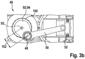
- the torque of the motor shaft 66 is transmitted to an eccentric shaft 92 via the second spur gear 79.
- the eccentric shaft 92 is rotatably mounted about an axis of rotation 93 in the gear housing 38.
- An eccentric element 94 designed as an eccentric disk is arranged on the top of the eccentric shaft 92, the eccentric shaft 92 and the eccentric element 94 preferably being designed in one piece.
- the translation element 48 designed as an eccentric pin, is firmly connected to the eccentric element 94. For better illustration, the transfer of the rotary movement into a linear movement is shown by the eccentric unit 46 in Fig. 3b shown from above.
- the crank element 50 is designed as a connecting rod which is rotatably connected to the translation element 48 and rotatably connected to the piston 52.
- the translation element 48 is arranged at a distance from the rotation axis 93 of the eccentric unit 46 and rotates about the rotation axis 93 along a circular path 100.
- the eccentricity 102 of the eccentric unit 46 results from the distance between the translation element 48 and the rotation axis 93, or the distance between the circular path 100 and the axis of rotation 93.
- the percussion mechanism 36 is designed as a pneumatic percussion mechanism.
- the striking mechanism 36 has a striking mechanism control 104, via which it can be switched from an idle mode to a working mode. Below the working axis 58, the percussion mechanism 36 is shown in idle mode and above the working axis 58 in working mode.
- the guide tube 40 has control openings 106 in the area between the racket 44 and the piston 52, via which a pressure equalization between the interior and the exterior of the guide tube 40 can be established.
- the control openings 106 are designed to be closable via a control sleeve 108, which is arranged outside the guide tube 40.
- the control sleeve 108 is subjected to a force in the direction of the idle position by means of a spring element 110 designed as a spiral spring.
- the handheld power tool 10 To move the handheld power tool 10 from idle mode to working mode To move it, it is pressed against a processing surface with the insert tool 30 inserted. Due to the force acting as a result, the insert tool 30, the bolt element 54 resting on the insert tool 30 and the striker 44 resting on the bolt element 54 are displaced axially in the direction of the rear end of the guide tube 40. The position of the striker 44 when the insert tool 30 is pressed is the impact point 112 of the impact mechanism 36.
- the axial mobility of the insert tool 30 or the bolt element 54 is limited via a B-impact damping system 114.
- the B impact damping system 114 is axially movably coupled to the impact mechanism control 104.
- the B-shock absorption system 114 is designed to dampen the kickback of the insert tool 30.
- the movement of the insert tool 30 is transmitted from the bolt element 54 to a pin element 116 which is movably mounted in a recess in the guide tube 40.
- a damping element 118 of the B-impact damping system 114 designed as a rubber ring is arranged outside the guide tube and connected to the pin element 116.
- the damping element 118 rests on the control sleeve 108 of the impact mechanism control 104 and moves it in the working mode in such a way that the control openings 106 of the guide tube 40 are closed by the control sleeve 108 against the spring force of the spring element 110.
- Fig. 4 the gearbox 28' and the tool holder 12' of the second hand-held power tool 10' are shown.
- the individual impact energy of the racket 44 is reduced by 1.5 to 2.0 joules via a crank stroke of the piston 52 that is reduced by approximately 20%.
- the ratio between the diameter of the guide tube 40, 40' and the piston stroke is 1.8, in particular 1.77, in the first hand-held power tool 10, and 1.4, in particular 1.44, in the second hand-held power tool 10'.
- the reduction in the crank stroke of the piston 52 is realized by reducing the eccentricity 102 'of the eccentric unit 46' compared to the eccentric unit 46 of the first hand-held power tool 10.
- the gearbox 28 of the first hand-held power tool 10 and the gearbox 28' of the second hand-held power tool 10' are accommodated in identical gearbox housings 38. This is achieved in particular by the fact that the gears 28, 28 'are largely similar. In particular, the bearing distance between the two bearing arrangements 88, 90 is identical in both hand-held power tools 10, 10'.
- the guide tube 40 of the first hand-held power tool 10 along the working axis 58 is designed in areas identical to the guide tube 40' of the second hand-held power tool 10'.
- the guide tubes 40, 40 ' are identically designed at least between their rear ends and the control openings 106, preferably at least between their rear ends and the impact mechanism controls 104, preferably between their rear ends and the B-impact damping systems 114.
- the diameter of the guide tubes 40, 40 ' is identical in the area of the piston 52 and in the area of the beater 44.
- first gear unit 32 of the second hand-held power tool 10' is designed identically to the first gear unit 32 of the first hand-held power tool 10.
- the impact point 112 of the second hand-held power tool 10' is identical to the impact point 112 of the first hand-held power tool 10. This is realized in particular by the elongated shape of the bolt element 54 'of the second hand-held power tool 10' compared to the bolt element 54 of the first hand-held power tool 10.
- the mass ratio between the bolt element 54 and the striker 44 is the first Hand-held power tool 10 substantially equal to the mass ratio between the bolt element 54' and the striker 44 of the second hand-held power tool 10'.
- the same B-impact damping system 114 can advantageously be optimized for both hand-held power tools 10, 10'.
- the air spring length 120 of the second hand-held power tool 10' is identical to the air spring length 120 of the first hand-held power tool 10. This is achieved in that the shorter crank stroke is compensated for by an extended crank element 50 ', so that the distance between the impact point 112 and the front reversal point of the piston 52 is the same.
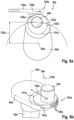
- FIG. 5a and Fig. 5b an alternative embodiment of the eccentric unit 46a is shown, wherein the eccentricity 102a of the eccentric unit 46a, in contrast to the previous eccentric units 46, 46 ', is not fixed but adjustable.
- Fig. 5a is the eccentric unit 46a in a cross section and in Fig. 5b shown in a perspective view.
- the eccentric unit 46a is designed to transmit a rotary drive movement into a linear movement.
- the eccentric unit 46a has a first eccentric element 94a designed as an eccentric disk, which is rotatably mounted about an axis of rotation 93a.
- the eccentric unit 46a also includes a second eccentric element 122a designed as an eccentric disk, which is designed to be movable relative to the first eccentric element 94a.
- the second eccentric element 122a is rotatably mounted about the rotation axis 93a and rotatable about an adjustment axis 123a.
- the second eccentric element 122a is, for example, partially accommodated by the first eccentric element 94a; alternatively, however, it is also conceivable that the second eccentric element 122a is designed to be placed on the first eccentric element 94a.
- a translation element 48a designed as an eccentric pin is connected to the second eccentric element 122a in a rotationally fixed manner.
- the eccentricity 102a of the adjustable eccentric unit 46a results from the distance between the circular path on which the translation element 48a moves about the rotation axis 93a and the rotation axis 93a.
- the eccentric unit 46a comprises an adjustment unit 124a, which is designed to rotate the second eccentric element 122a, in particular the translation element 48a, about the adjustment axis 123a and to adjust it into at least two different positions, each of which has a different eccentricity 102a.
- the adjustment unit 124a comprises two mutually corresponding adjustment elements 126a, 128a, which are designed to form a positive connection with one another.
- the first adjusting element 126a is formed in one piece with the second eccentric element 122a as an external toothing.
- the second adjustment element 128a is designed as an actuator element 130a, which is accommodated in the housing of the hand-held power tool in a linearly movable manner, for example.
- the actuator element 130a has a toothing that corresponds to the external toothing of the first adjusting element 126a.
- the teeth of the adjusting elements 126a, 128a engage with one another in such a way that a linear movement of the actuator element 130a is transferred into a rotary movement of the second eccentric element 122a about the adjusting axis 123a.
- the rotational movement of the second eccentric element 122a is limited between the two adjustable positions via a stop 131a.
- the eccentric unit 46a has different eccentricities 102a, which allows the crank stroke to be advantageously varied.
- the actuator element 130a can advantageously be controlled or regulated automatically or semi-automatically via electronics of the hand-held power tool. Alternatively or additionally, it is also conceivable that the actuator element 130a is mechanically coupled to an operating element, not shown, in order to enable manual actuation of the actuator element 130a.
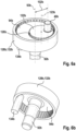
- FIG. 6a to Fig. 6d an alternative embodiment of an adjustable eccentric unit 46b is shown.
- the eccentric unit 46b comprises an eccentric shaft 92b, a first and a second eccentric element 94b, 122b, wherein the first eccentric element 94b is rotatably mounted about a rotation axis 93b and the second eccentric element 122b is rotatably mounted about the rotation axis 93b and the adjustment axis 123b.
- a translation element 48b is connected to the second eccentric element 94b in a rotationally fixed manner.
- the setting unit 124b of the eccentric unit 46b is designed to adjust the eccentricity 102b in several different positions between a maximum and a minimum eccentricity 102b.
- the setting unit 124b comprises two corresponding setting elements 126b, 128b.
- the first adjusting element 126b is designed as an external toothing of the second eccentric element 122b.
- the second eccentric element 122b is in particular designed as a gear that is rotatably arranged on the first eccentric element 94b.
- the second adjusting element 128b is rotatably mounted in the housing about the axis of rotation 93b.
- the second adjusting element 128b is in engagement with the first adjusting element 126b via a toothing that corresponds to the external toothing.
- the second adjusting element 128b is designed as a ring gear 132b.
- the ring gear 132b encloses both the first and the second eccentric elements 94b, 122b. Above the first eccentric element 94b, the ring gear 132 is in engagement with the second eccentric element 122b, which is designed as a gear, and below the first eccentric element 94b, the ring gear 132b is in engagement with a drive element 134b.
- the drive element 134b is coupled to the ring gear 132b via a front pinion.
- the drive element 134b can be driven and/or braked via a drive unit, not shown, which comprises, for example, a motor.
- the ring gear 132b is designed to be drivable independently of the first eccentric element 94b via the drive element 134b.
- the eccentricity 102b can advantageously be adjusted via a relative movement of the ring gear 132b to the first eccentric element 94b.
- the ring gear 132b moves at the same rotational speed as the first eccentric element 94b during the impact operation of the hand-held power tool, so that the eccentricity 102b of the eccentric unit 46b is constant during the impact operation.
- the eccentricity 102b is varied during the impact operation.
- the drive element 134b can be controlled such that the eccentricity 102b preferably changes periodically in order to generate a variable impact mechanism pressure.
- the eccentric unit 46b is shown in a position 136b with a maximum eccentricity 102b and in a position 138b with a minimum eccentricity 102b.
- the number of possible positions into which the second eccentric element 94b can be adjusted between the positions 136b, 138b can be determined via the number of teeth of the toothings of the adjusting elements 126b, 128b be determined.
- the translation element 48b is arranged essentially centrally on the axis of rotation 93b, so that the eccentricity 102b is essentially zero and no crank stroke is generated by the eccentric unit 46b in this position.
- the setting unit 124b can advantageously be designed to switch off a percussion mechanism of the hand-held power tool.
- the eccentric unit is in a different way, for example as in US 6505582 described, can be designed.
- the overload device 42 is advantageously designed in such a way that a high transferable transmission power can be achieved with a low size and weight.
- the overload device 42 comprises a first coupling element 140 and a second coupling element 142, which can be coupled to one another in a rotationally fixed manner via an overload unit 144.
- the first coupling element 140 is coupled to the second coupling element 142 for torque transmission as long as a maximum torque is not exceeded.
- the first coupling element 140 is advantageously decoupled from the second coupling element 142 if the maximum torque is exceeded.
- the first and second coupling elements 140, 142 In the coupled state, the first and second coupling elements 140, 142 have the same speed, whereas in the decoupled state, the speed of the first coupling element 140 differs from the speed of the second coupling element 142.
- the first coupling element 140 is designed as a part of the spur gear 78.
- the first coupling element 140 has spur gear teeth on its circumferential outer surface, which meshes with the motor shaft 66.
- the second coupling element 142 is connected to the coupling shaft 80 in a rotationally fixed manner.
- the second coupling element 142 has recesses 145 which extend essentially radially and in each of which an overload unit 144 is arranged to be linearly movable.
- the overload unit 144 includes an overload element 146 and a spring element 148, which apply a force to the overload element 146.
- the compactness of the overload device 42 results in particular from the low height 150 and length 152 of the overload device 42.
- the ratio between the height 150 and length 152 of the overload device 42 is advantageous in a range between 0.18 and 0.22.
- the ratio between height 150 and length 152 of the overload device 42 in the exemplary embodiment shown is approximately 0.20.
- the length 152 of the overload device 42 does not exceed the diameter of the ring gear 86 by more than 20%, preferably by not more than 10%.
- the diameter of the ring gear 86 exceeds the length 152 of the overload device 42 by approximately 5%.
- a very compact first gear unit 32 can also be realized due to the short length 152 of the overload device 42.
- the ratio of the height 154 of the first gear unit 32 to the length 156 of the first gear unit 32, which corresponds to the length 152 of the overload device 42, is in a range between 1.3 and 1.5. In the embodiment shown the ratio is approximately 1.45.
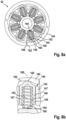
- Fig. 8a a section through the overload device 42 is shown in a cross section.
- the overload device 42 is in the coupled state.
- the first coupling element 140 encloses the second coupling element 142.
- the overload unit 144 is arranged in the recesses 145 of the second coupling element 142 in such a way that the second coupling element 142 and the overload unit 144 are coupled to one another in a rotationally fixed manner about the coupling axis 81.
- the overload device 42 comprises seven recesses 145 in each of which an overload unit 144 is arranged.
- the overload element 146 is subjected to a force radially to the coupling axis 81 by the spring element 148.
- the head 160 of the overload element 146 acts on the first coupling element 140, in particular a latching profile 162 on the inner circumferential surface of the first coupling element 140.
- the latching profile 162 comprises seven latching segments, each of which has an ascending and a descending ramp.
- the locking segments are designed symmetrically, so that the gradient of the ascending ramp is identical to the gradient of the descending ramp.
- the overload unit 144 thus couples the rotational movement of the first coupling element 140 with the rotational movement of the second coupling element 142.
- the torque to be transmitted from the motor shaft 66 to the insert tool 30 via the first coupling element 140 can no longer be transmitted, since the coupling shaft 80 coupled to the insert tool is also blocked.
- a locking process takes place in which the overload elements 146 slide from one pocket of the locking profile 162 to the next until the blocking is released or the hand-held power tool 10 is switched off.
- Fig. 8b is the one in Fig. 8a marked area shown in an enlarged view.
- the compact design is achieved by a particularly compact spring element 148.
- the spring element 148 is designed as a helical compression spring.
- the spring element 148 comprises a total number of turns of seven, with five turns being designed to be resilient.
- the spring element has a spring stiffness of at least 50N/mm with a dynamic stroke of up to 1.5 mm.
- the spring element 148 rests axially on a flat stop surface 164 of the second coupling element 142 and on the overload element 146, in particular on an inner surface of the overload element 146 opposite the head 160.
- the spring element 148 is guided by the overload element 146.
- the overload element 146 has two guide arms 147, which are arranged opposite one another and which guide the spring element 148.
- the guide arms 147 are arranged in the recesses 145 both in the coupled and in the decoupled state, while the head 160 only in the decoupled state is partially arranged in the recess 145.
- the guiding ratio between the length of the spring element 148 and the length of the area in which the spring element 148 is guided by the overload element 146 is approximately 1.13 in the coupled state.
- the spring element 148 is guided exclusively by the overload element 146.
- the spring element 148 is not guided by the second coupling element 142.
- the recesses 145 of the second coupling element 142 are connected to one another via a circumferential groove 166 which extends around the coupling axis 81.
- the spring element 148 is partially arranged in this groove 166.
- the spring element 148 lies against the second coupling element 142 in the area of the groove 166.
- the spring element 148 has a constant diameter, in particular the outside diameter.
- the overload element 146 is accommodated in the recess 145 in a linearly movable, tiltable manner.
- the distance between the recess 145 and the overload element 146 along a longitudinal extension 168 of the overload element 146, which extends coaxially to a radial extension 83 of the coupling axis 81, in particular in the coupled state of the overload device 42 is not constant.
- the distance between the recess 145 and the overload element 146 increases steadily in the direction of the coupling axis 81, which enables tilting.
- the recess 145 is straight and the overload element 146 is oblique or conical.
- the term straight should be understood in particular to mean that the surface of the recess 145, against which the overload element 146 rests, is designed essentially parallel to the longitudinal extent 168 of the overload element 146.
- the term oblique is intended to mean in particular that the outer surface of the overload element 146 has a slight angular offset from the longitudinal extension 168, which is, for example, approximately 5°.
- the recess 145 is designed obliquely or that the recess 145 is designed obliquely and the overload element 146 is straight.
- the overload element 146 is also obliquely or conically shaped on its inner surface. So the distance between is also the spring element 148 and the overload element 146 steadily increasing in the direction of the coupling axis 81.
- the spring element 148 is conical.
- the guide arms 147 are obliquely or conically shaped both on their inner side facing the spring element 148 and on their outer side facing the recess 145.
- Fig. 8c the overload device 42 is shown in the decoupled state. Due to a relative movement of the first coupling element 140 to the second coupling element 142, the overload element 146 experiences a force via the locking profile 162 against the force of the spring element 148. As a result, the overload element 146 moves into the recess 145 in such a way that the head 160 is also partially is arranged in the recess 145, and on the other hand the overload element 146 is tilted. In particular, the overload element 146 is tilted in such a way that the radial extent 83 and the longitudinal extent 168 of the overload element 146 have an angular offset of approximately 4°.
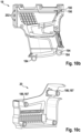
- Fig. 9a to Fig. 9d the hand power tools 10, 10', 10" and 10" are each shown in a side view.
- the housings 16, 16', 16", 16" of the hand power tools 10, 10', 10", 10" are based on a common housing concept, so that the first housing part 18 of the hand-held power tools 10, 10', 10", 10" is designed identically.
- Fig. 9a the housing 16 of the first hand-held power tool 10 is shown.
- the first housing part 18 has two housing half-shells connected to one another via screw connections.
- the first housing part 18 encloses the motor 26 and the transmission 28.
- the motor 26 and the transmission 28 are arranged essentially completely within the space spanned by the housing half-shells of the first housing part 18.
- the first housing part 18 includes air openings 170 which are designed to supply the motor 26 and/or the transmission 28 with cooling air.
- An operating mode switching element 56 can be arranged on the top of the first housing part 18.
- the gear housing 38 is mounted via bearing points 174.
- the gearbox 38 is supported exclusively by the first housing part 18.
- the first housing part 18 is connected to the second housing part 20, the third housing part 22 and the fourth housing part 24 via three housing interfaces 178, 180, 182.
- the second housing part 20 is immovably attached to the first housing part 18 via the first housing interface 178.
- the second housing part 20 is designed as an electronics housing in which the electronics 68 is arranged.
- the second housing part 20 preferably also includes air openings 183 which are designed to cool the electronics 68.
- the second housing part 20 comprises two housing half-shells that are connected to one another via a screw connection.
- the third housing part 22 designed as a handle 60, is movably attached to the first housing part 18 via the second housing interface 180.
- the control element 64, designed as an operating switch, and the battery interface 70 are arranged on the third housing part 22.
- the third housing part 22 has two housing half-shells that are connected to one another via a screw connection.
- the fourth housing part 24 is immovably attached to the first housing part 18 via the third housing interface 182.
- the fourth housing part 24 partially encloses the tool holder 12 and has air openings 185 for cooling.
- the fourth housing part 24 is formed in one piece.
- the fourth housing part 24 has a tubular shape.
- Fig. 9b the housing 16' of the second hand-held power tool 10' is shown. Since the first hand-held power tool 10 and the second hand-held power tool 10' differ from each other essentially by the tool holders 12, 12', the first, second and third housing parts are 18, 20, 22 of the two Hand tool tools 10, 10 'are identical to one another.
- the fourth housing part 24 'of the second hand-held power tool 10' differs from the fourth housing part 24 of the first hand-held power tool 10 in particular in its compactness and length. Due to the more compact tool holder 12' of the second hand tool 10' compared to the tool holder 12 of the first hand tool 10, the housing 16' of the second hand tool 10' can be adapted to the shape of the tool holder 12' via the fourth housing part 24'.
- the housing interface 182 is designed identically to one another in the hand-held power tools 10, 10'.
- Fig. 9c is the third hand tool 10" and in Fig. 9d the fourth hand tool 10′′′ is shown.
- the third hand-held power tool 10′′ is designed as a network variant of the first hand-held power tool 10 and the fourth hand-held power tool 10′′′ as a network-based variant of the second hand-held power tool 10′.
- the third and fourth hand-held power tools 10′′, 10′′′ each have a different second Housing part 20" and a different third housing part 22".
- the hand-held power tools 10", 10" each have a network interface 188, which is arranged at the lower end of the third housing part 22" designed as a handle 60". In the area of the network interface 188, entry occurs via an opening in the third housing part 22".
- the housing interfaces 178, 180, 182 in the handheld power tools 10, 10', 10", 10" are advantageously designed to be identical to one another.
- another hand-held power tool has identical housing parts 18, 20, 24 and only the third housing part 22 differs by an alternative battery interface 70 for receiving an alternative hand-held power tool battery pack, which, for example, has a different number of battery cells.
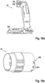
- Fig. 10a-e the housing interfaces 178, 180, 182 are shown using the housing 16 of the first hand-held power tool 10.
- Fig. 10a shows one Longitudinal section through the housing 16 and Fig. 10b to Fig. 10e each show a housing part 18, 20, 22, 24, or a housing half-shell of the housing parts 18, 20, 22, 24.
- the first housing interface 178 has mutually corresponding connecting elements 184, 186, which can be connected to one another in a form-fitting manner.
- the connecting elements 184 are assigned to the first housing part 18, the connecting elements 186 are assigned to the second housing part 20.
- the first housing part 18 has a pair of connecting elements 184 which are designed as a circular receptacle.
- the connecting elements 184 are formed in one piece with the first housing part 18.
- the two connecting elements 184 form the lower end of the first housing part 18.
- the second housing part 20 also has a few connecting elements 186, which are designed as a pin-shaped extension which extends vertically starting from the inner surface of the second housing part 20.
- the connecting element 186 extends essentially perpendicular to the longitudinal and vertical extent of the hand-held power tool 10.
- the connecting element 186 is advantageously designed as a screw dome 187, via which the two housing half-shells of the second housing part 20 can be connected by means of a screw connection. In the connected state, the connecting elements 186 are enclosed or received in a form-fitting manner by the connecting elements 184.
- the second housing interface 180 pivotally attaches the third housing part 22 to the first housing part 18.
- the handle is pivotally attached to the first housing part 18 via three axes of rotation 190, 192, 194.
- the axes of rotation 190, 192 are arranged at the upper end of the housing 16.
- the corresponding connecting elements 196, 198 are designed as pivot bearing elements that support the damping unit 62.
- the connecting elements 196, 198 are formed in one piece with the housing parts 18, 22.
- the damping unit 62 is designed as a sprung connecting rod element.
- the third housing part 22 has a further connecting element 200 designed as a circular receptacle, which is designed to be positively connectable to the connecting element 186 of the second housing interface 178.
- the connecting element 186 of the second is in the connected state Housing part 20 is received in a form-fitting manner by the connecting element 184 of the first housing part 18 and the connecting element 200 of the third housing part 22.
- the third housing interface 182 has two corresponding connecting elements 202, 204, which interlock with one another in a form-fitting manner.
- the connecting element 202 is assigned to the first housing part 18 and is designed as an extension which extends inwards from the inner surface of the first housing part 18.
- the fourth housing part 24 is enclosed at a front end region 206 by the two housing half-shells of the first housing part 18 in such a way that the extensions 202 engage in the corresponding connecting elements 204 of the fourth housing part 24, which are designed as openings.
- the fourth housing part 24 is thus fixed radially by the first housing part 18 and axially and in the direction of rotation about the working axis 58 by the connecting elements 202 of the first housing part 18.
- the hand-held power tools 10, 10', 10", 10"", which are constructed essentially as described above have an alternative second housing part 20c.
- the alternative second housing part 20c in particular includes electronics 68 and an additional functional unit 208c.
- the second housing part 20c can be connected to another housing part of the hand-held power tool via a housing interface (not shown).
- the second housing part 20c can be formed in one piece in a pot design or, as already described above, in a half-shell housing design.
- the additional functional unit 208c is designed as a lighting element 210c.
- the lighting elements 210c can, for example, emit a bright light to illuminate a processing surface or a colored light to display a status of the hand-held power tool.
- the lighting elements 210c are arranged to the front, in particular in the processing direction. Alternatively or additionally, it is also conceivable that at least one lighting element 212c is arranged laterally.
- the side lighting element 212c is preferably designed to display a status. It is conceivable, for example, that a safety function could be triggered due to a blocking of the tool, a low battery level, an operating temperature that is too high, etc. can be displayed via the lighting elements 210c and/or the lighting element 212c. In the Fig.
- the additional functional unit 208c is designed as a coupling means 214c for an accessory device (not shown).
- the coupling means 214c is designed as a pair of guide rails for a dust extraction device for a hammer drill.
- the hand-held power tool, in particular the second housing part 20c, can advantageously be connected to an accessory device via the coupling means 214c.
- the additional functional unit 208c is designed as a distance meter 216c, which measures the distance to the processing surface using laser distance measurement.
- further additional functional units 208c such as a projection unit for projecting information, patterns, a spirit level or a running time counter or an anti-theft module, are conceivable.
Landscapes
- Engineering & Computer Science (AREA)
- Mechanical Engineering (AREA)
- Percussive Tools And Related Accessories (AREA)
Description
- Es sind bereits Bohrhammer mit Exzenterschlagerwerken unterschiedlicher Leistungsklassen sowohl als Akkugeräte als auch als Netzgeräte bekannt.
- Zudem ist in der
DE 10002748 A1 ein Bohrhammer mit einer Sicherheitskupplung zur Übertragung eines Drehmoments beschrieben, wobei die Sicherheitskupplung zwei Kupplungselemente aufweist, die über ein Rastelement miteinander verbunden sind, das beim Überschreiten eines bestimmten Drehmoments ausrastet. Relevanter Stand der Technik kann in derEP 1 052 070 A2 und in derWO 2016/172480 A1 gefunden werden. - Die Erfindung betrifft ein System aus einer ersten Handwerkzeugmaschine und einer zweiten Handwerkzeugmaschine mit jeweils einem Schlagwerk, mit jeweils einem Motor, mit jeweils einem das Schlagwerk umfassenden Getriebe, das dazu ausgebildet ist, eine Antriebsbewegung des Motors auf ein in einer Werkzeugaufnahme aufgenommenes Einsatzwerkzeug zu übertragen, wobei die jeweiligen Getriebe ein bereichsweise entlang einer Arbeitsachse identisches Führungsrohr aufweisen, in welchem ein Schläger axial beweglich gelagert ist, wobei das Führungsrohr über eine erste Getriebeeinheit drehbar mit dem Motor gekoppelt ist und wobei der Schläger über einen Kolben einer zweiten Getriebeeinheit linear oszillierend antreibbar ist.
- Die Handwerkzeugmaschine ist insbesondere dazu ausgebildet, ein Einsatzwerkzeug drehend um und/oder schlagend entlang einer Arbeitsachse anzutreiben. Die Arbeitsachse erstreckt sich im Wesentlichen entlang der Längserstreckung der ersten beziehungsweise der zweiten Handwerkzeugmaschine. Das Einsatzwerkzeug kann beispielhaft als Bohrer oder Meißel ausgebildet sein. Bei dem Einsatzwerkzeug handelt es sich um ein Verschleißteil, das lösbar in der Werkzeugaufnahme befestigbar ist. Das Einsatzwerkzeug weist ein Einsteckende auf, das in der Werkzeugaufnahme der Handwerkzeugmaschine aufgenommen wird. Die Einsteckenden von Einsatzwerkzeugen weisen üblicherweise einen standardisierten Schaftdurchmesser auf, der auf unterschiedliche Geräteklassen, beziehungsweise Gerätegrößen, ausgelegt ist, beispielhaft einen 10 mm Schaftdurchmesser für SDS-plus Werkzeugaufnahmen und einen 18 mm Schaftdurchmesser für SDS-Max Werkzeugaufnahmen.
- Die Werkzeugaufnahme umfasst bevorzugt ein Wechselbohrfutter oder ein Festbohrfutter. Unter einem "bereichsweise entlang einer Arbeitsachse identischen Führungsrohr" soll insbesondere ein Führungsrohr verstanden werden, das zumindest zu 33%, vorzugsweise zumindest zu 50%, insbesondere zumindest zu 66% der Länge des Führungsrohrs entlang der Längserstreckung der Handwerkzeugmaschine identisch zu einem anderen Führungsrohr ist. Insbesondere ist der Innen- und/oder Außendurchmesser des Führungsrohrs der ersten Handwerkzeugmaschine und der zweiten Handwerkzeugmaschine zumindest bereichsweise entlang der Arbeitsachse identisch. Das Führungsrohr der ersten und/oder der zweiten Handwerkzeugmaschine kann einteilig oder mehrteilig ausgebildet sein. Insbesondere ist das Führungsrohr der ersten Handwerkzeugmaschine und der zweiten Handwerkzeugmaschine in einem Bereich zwischen dem hinteren Ende, das der Werkzeugaufnahme abgewandt ist, und einer Steueröffnung oder dem B-Schlagdämpfungssystem identisch. Zudem ist ein Verhältnis zwischen einem Durchmesser der Werkzeugaufnahme und einem Durchmesser des Führungsrohrs bei der ersten Handwerkzeugmaschine um das 1,8 fache größer, als bei der zweiten Handwerkzeugmaschine. Unter einem "Durchmesser der Werkzeugaufnahme" soll insbesondere ein Innendurchmesser der Werkzeugaufnahme verstanden werden, der an die Schaftgröße des Einsatzwerkzeugs angepasst ist. Unter einem "Durchmesser des Führungsrohrs" soll insbesondere der Innendurchmesser des Führungsrohrs verstanden werden.
- Es wird vorgeschlagen, dass eine Einzelschlagenergie der zweiten Handwerkzeugmaschine im Vergleich zu einer Einzelschlagenergie der ersten Handwerkzeugmaschine mechanisch verringert ist. Vorteilhaft kann dadurch die zweite Handwerkzeugmaschine auf einfache Weise auf einen unterschiedlichen Anwendungsbereich angepasst werden. Unter einer "Einzelschlagenergie" soll insbesondere die Energie verstanden werden, die während des Betriebs der Handwerkzeugmaschine auf den Schläger übertragen oder die von dem Schläger auf das Einsatzwerkzeug übertragen wird. Unter "mechanisch verringert" soll insbesondere verstanden werden, dass die Einzelschlagenergie durch das Getriebe, vorzugsweise durch die zweite Getriebeeinheit des Getriebes, verringert wird. Bevorzugt wird die Einzelschlagenergie der zweiten Handwerkzeugmaschine um zumindest 10%, insbesondere zumindest 17,5%, vorzugsweise um zumindest 25%, verringert. In absoluten Zahlen entspricht dies einer Verringerung der Einzelschlagenergie bei einem Durchmesser des Führungsrohrs von ca. 30 mm von über 0,5 Joule, insbesondere 1,5 bis 2,0 Joule. Zusätzlich oder alternativ wird vorgeschlagen, dass die Schlagleistung der zweiten Handwerkzeugmaschine im Vergleich zu einer Schlagleistung der ersten Handwerkzeugmaschine mechanisch verringert ist. Bevorzugt ist die Schlagfrequenz des Schlagwerks der ersten Handwerkzeugmaschine im Wesentlichen identisch zu der Schlagfrequenz der zweiten Handwerkzeugmaschine.
- Des Weiteren wird vorgeschlagen, dass ein Kurbelhub der zweiten Getriebeeinheit der zweiten Handwerkzeugmaschine im Vergleich zu einem Kurbelhub der zweiten Getriebeeinheit der ersten Handwerkzeugmaschine verringert, insbesondere um 10% verringert, vorzugsweise um 15% verringert, bevorzugt um 20% verringert, ist. Vorteilhaft kann dadurch die Einzelschlagenergie bei gleichbleibender Schlagfrequenz gesenkt werden. Unter einem Kurbelhub soll insbesondere der axiale Abstand zwischen den beiden Umkehrpunkten des Kolbens im Führungsrohr verstanden werden. Insbesondere wirkt an den beiden Umkehrpunkten keine axiale Kraft auf den Kolben.
- Weiterhin wird vorgeschlagen, dass der Kolben der ersten und der zweiten Handwerkzeugmaschine über jeweils eine Exzentereinheit angetrieben werden, wobei eine Exzentrizität der Exzentereinheit der zweiten Handwerkzeugmaschine kleiner ist, als eine Exzentrizität der Exzentereinheit der ersten Handwerkzeugmaschine. Vorteilhaft kann dadurch der Kurbelhub auf einfache Weise angepasst werden. Die Exzentereinheit ist der zweiten Getriebeeinheit zugeordnet. Die Exzentereinheit wird um eine Rotationsachse durch den Motor angetrieben. Die Exzentereinheit weist ein als Exzenterpin ausgebildetes Übersetzungselement auf, das über ein Kurbelelement mit dem Kolben verbunden ist. Das Übersetzungselement bewegt sich um die Rotationsachse auf einer insbesondere kreisförmigen Bahn. Die Exzentrizität der Exzentereinheit ergibt sich aus dem Abstand zwischen der Rotationsachse der Exzentereinheit und der Bahn, auf der sich das Übersetzungselement bewegt.
- Zudem wird vorgeschlagen, dass sich eine Luftfederlänge des Schlagwerks der ersten Handwerkzeugmaschine von einer Luftfederlänge des Schlagwerks der zweiten Handwerkzeugmaschine unterscheidet, insbesondere größer ist. Vorteilhaft kann durch eine geringere Luftfederlänge des Schlagwerks die Einzelschlagenergie auf konstruktiv einfache Weise verringert werden. Unter einer Luftfederlänge des Schlagwerks soll insbesondere ein minimaler Abstand zwischen dem Schläger und dem Kolben oder ein Abstand zwischen dem Schläger und dem Kolben am vorderen, der Werkzeugaufnahme zugewandtem, Umkehrpunkt verstanden werden. Die Luftfederlänge kann beispielhaft über die Form des Schlägers, die Form des Kolbens oder die Form des Kurbelelements angepasst werden.
- Des Weiteren wird vorgeschlagen, dass ein Lagerabstand des Schlagwerks der ersten Handwerkzeugmaschine gleich einem Lagerabstand des Schlagwerks der zweiten Handwerkzeugmaschine ist. Unter einem Lagerabstand soll dabei insbesondere ein Abstand zwischen zwei Bereichen verstanden werden, über die das Führungsrohr des Schlagwerks gelagert ist. Insbesondere ist der Lagerabstand als ein Abstand zwischen einem Axial- oder Radiallager und einem weiteren Axial- oder Radiallager, die jeweils das Führungsrohr lagern. Vorzugsweise ist der Lagerabstand als ein Abstand zwischen zwei Radiallagern ausgebildet.
- Weiterhin wird vorgeschlagen, dass ein Schlagpunkt der ersten Handwerkzeugmaschine gleich einem Schlagpunkt der zweiten Handwerkzeugmaschine ist. Unter einem Schlagpunkt soll insbesondere die Position des Schlägers, insbesondere des hinteren, der Werkzeugaufnahme abgewandten, Endes des Schlägers, im Führungsrohr, während das Einsatzwerkzeug gegen die Bearbeitungsoberfläche gedrückt wird, verstanden werden. Vorzugsweise ist sowohl der Schlagpunkt als auch die Luftfederlänge der ersten Handwerkzeugmaschine identisch zu dem Schlagpunkt und der Luftfederlänge der zweiten Handwerkzeugmaschine.
- Zudem wird vorgeschlagen, dass die erste und die zweite Handwerkzeugmaschine jeweils ein B-Schlagdämpfungssystem aufweisen, die identisch zueinander ausgebildet sind. Unter einem B-Schlagdämpfungssystem soll insbesondere eine Anordnung von Bauteilen im Schlagwerk verstanden werden, die dazu ausgebildet sind, den Rückstoß des Einsatzwerkzeugs entgegen der Schlagrichtung zu dämpfen. Der Schläger überträgt seine Energie über ein Bolzenelement auf das Einsatzwerkzeug. Das B-Schlagdämpfungssystem ist zumindest teilweise im Führungsrohr angeordnet und umfasst zumindest ein Dämpfungselement, das innerhalb und/oder außerhalb des Führungsrohrs angeordnet sein kann. Vorzugsweise ist das Massenverhältnis zwischen dem Bolzenelement und dem Schläger bei der ersten Handwerkzeugmaschine identisch zu der zweiten Handwerkzeugmaschine, sodass das gleiche B-Schlagdämpfungssystem vorteilhaft sowohl auf die erste als auch die zweite Handwerkzeugmaschine optimiert sein kann.
- Des Weiteren wird vorgeschlagen, dass die erste und die zweite Handwerkzeugmaschine jeweils ein Getriebegehäuse aufweisen, wobei die mechanischen Bauteile innerhalb der Getriebegehäuse zu zumindest 80%, insbesondere zu zumindest 90%, identisch sind. Das Getriebegehäuse kann als ein Außengehäuse und/oder als ein internes Gehäuse ausgebildet sein.
- Weiterhin wird vorgeschlagen, dass ein Durchmesser der Werkzeugaufnahme der zweiten Handwerkzeugmaschine unter 18 mm, insbesondere 10 mm, ist, und dass das Verhältnis zwischen einem Durchmesser des Führungsrohrs und dem Durchmesser der Werkzeugaufnahme der zweiten Handwerkzeugmaschine in einem Bereich zwischen 2,8 und 3,4, insbesondere in einem Bereich zwischen 2,9 und 3,1, liegt. Vorteilhaft kann dadurch eine besonders leistungsstarke Handwerkzeugmaschine realisiert werden.
- Weitere Vorteile ergeben sich aus der folgenden Zeichnungsbeschreibung. Die Zeichnungen, die Beschreibung und die Ansprüche enthalten zahlreiche Merkmale in Kombination. Der Fachmann wird die Merkmale zweckmäßigerweise auch einzeln betrachten und zu sinnvollen weiteren Kombinationen zusammenfassen.
- Es zeigen:
- Fig. 1
- einen Längsschnitt einer ersten Handwerkzeugmaschine;
- Fig. 2
- einen Längsschnitt einer zweiten Handwerkzeugmaschine;
- Fig. 3a
- einen Längsschnitt eines Getriebes der ersten Handwerkzeugmaschine;
- Fig. 3b
- einen Querschnitt einer Exzentereinheit des Getriebes der ersten Handwerkzeugmaschine;
- Fig. 4
- einen Längsschnitt eines Getriebes der zweiten Handwerkzeugmaschine;
- Fig. 5a
- einen Querschnitt einer zweiten Ausführungsform der Exzentereinheit;
- Fig. 5b
- eine perspektivische Ansicht der Exzentereinheit gemäß
Fig. 5a ; - Fig. 6a
- eine perspektivische Ansicht einer dritten Ausführungsform der Exzentereinheit;
- Fig. 6b
- eine weitere perspektivische Ansicht der Exzentereinheit gemäß
Fig. 6a ; - Fig. 6c
- einen Querschnitt der Exzentereinheit gemäß
Fig. 6a ; - Fig. 6d
- einen weiteren Querschnitt der Exzentereinheit gemäß
Fig. 6a ; - Fig. 7
- eine vergrößerte Darstellung des Getriebes nach
Fig. 3 ; - Fig. 8a
- einen Querschnitt einer Überlastvorrichtung;
- Fig. 8b
- eine vergrößerte Darstellung einer Überlasteinheit der Überlastvorrichtung gemäß
Fig. 8a ; - Fig. 8c
- eine weitere vergrößerte Darstellung einer Überlasteinheit der Überlastvorrichtung gemäß
Fig. 8a ; - Fig. 9a
- eine Seitenansicht eines Gehäuses der ersten Handwerkzeugmaschine;
- Fig. 9b
- eine Seitenansicht eines Gehäuses der zweiten Handwerkzeugmaschine;
- Fig. 9c
- eine Seitenansicht eines Gehäuses einer dritten Handwerkzeugmaschine;
- Fig. 9d
- eine Seitenansicht eines Gehäuses einer vierten Handwerkzeugmaschine;
- Fig. 10a
- einen Längsschnitt durch das Gehäuse gemäß
Fig. 9a ; - Fig. 10b
- eine Seitenansicht einer Gehäusehalbschale des ersten Gehäuseteils;
- Fig. 10c
- eine perspektivische Ansicht einer Gehäusehalbschale des zweiten Gehäuseteils;
- Fig. 10d
- eine Seitenansicht einer Gehäusehalbschale des dritten Gehäuseteils;
- Fig. 10e
- eine perspektivische Ansicht des vierten Gehäuseteils;
- Fig. 11a
- eine schematische Ansicht eines alternativen zweiten Gehäuseteils;
- Fig. 11b
- eine weitere schematische Ansicht eines alternativen zweiten Gehäuseteils;
- Fig. 11c
- eine schematische Ansicht eines weiteren alternativen zweiten Gehäuseteils.
- In den folgenden Zeichnungen sind vier Varianten einer Handwerkzeugmaschine gezeigt. Die Handwerkzeugmaschinen sind dazu ausgelegt, möglichst viele gleiche Bauteile zu umfassen, um kostengünstig unterschiedliche Einsatzgebiete abzudecken. Gleiche Bauteile und gleiche Baueinheiten werden im Folgenden mit den gleichen Bezugszeichen versehen. Die verschiedenen Varianten der Handwerkzeugmaschine werden durch die Anzahl an Apostrophen hinter dem Bezugszeichen gekennzeichnet. Unterschiedliche Ausführungsform von Bauteilen oder Baueinheiten, die einer oder mehreren spezifischen Varianten der Handwerkzeugmaschine zugeordnet sind, werden ebenfalls mit der gleichen Anzahl an Apostrophen gekennzeichnet. Alternative Ausführungsformen der Bauteile oder Baueinheiten, die grundsätzlich für zumindest zwei Varianten in Frage kommen, werden mit einem Buchstaben hinter dem Bezugszeichen gekennzeichnet.
- Die erste Handwerkzeugmaschine 10 (siehe
Fig. 1 ) und die zweite Handwerkzeugmaschine 10' (sieheFig. 2 ) sind als Akku-Handwerkzeugmaschinen ausgebildet. Die beiden Handwerkzeugmaschinen 10, 10' weisen jeweils eine Werkzeugaufnahme 12, 12' auf, die sich in ihrem Durchmesser 14, 14' voneinander unterscheiden. Insbesondere ist zudem die Werkzeugaufnahme 12 als ein festes Bohrfutter und die Werkzeugaufnahme 12' als ein Wechselbohrfutter ausgebildet. Beispielhaft ist die erste Handwerkzeugmaschine 10 mit einer SDS-max Werkzeugaufnahme 12 und die zweite Handwerkzeugmaschine 10' mit einer SDS-plus Werkzeugaufnahme 12' ausgebildet. Der Durchmesser 14 der SDS-max Werkzeugaufnahme 12 beträgt im Wesentlichen 18 mm und der Durchmesser 14' der SDS-plus Werkzeugaufnahme 12' beträgt im Wesentlichen 10 mm, wodurch sich ein Verhältnis zwischen dem Durchmesser 14 der Werkzeugaufnahme 12 der ersten Handwerkzeugmaschine 10 und dem Durchmesser 14' der Werkzeugaufnahme 12' der zweiten Handwerkzeugmaschine 10' von 1,8 ergibt. Die dritte Handwerkzeugmaschine 10" (sieheFig. 9c ) und die vierte Handwerkzeugmaschine 10‴ (sieheFig. 9d ) sind jeweils als Netz-Handwerkzeugmaschinen mit einer SDS-max Werkzeugaufnahme 12 und einer SDS-plus Werkzeugaufnahme 12' ausgebildet. - In
Fig. 1 ist ein Längsschnitt durch die erste Handwerkzeugmaschine 10 gezeigt. Die Handwerkzeugmaschine 10 ist als ein Bohrhammer ausgebildet. Die Handwerkzeugmaschine 10 weist ein Gehäuse 16 auf, das aus mehreren Gehäuseteilen 18, 20, 22, 24 ausgebildet ist. Die Gehäuseteile 18, 20, 22, 24 sind als Au-ßengehäuse ausgebildet. Es ist alternativ oder zusätzlich auch denkbar, dass zumindest eines der Gehäuseteile 18, 20, 22, 24 teilweise oder vollständig als Innengehäuse ausgebildet ist. Innerhalb des ersten Gehäuseteils 18 ist ein Motor 26 angeordnet. Der Motor 26 ist in den Varianten der Handwerkzeugmaschine 10, 10' als Akku-Handwerkzeugmaschine als insbesondere bürstenloser Gleichstrommotor und in den Varianten der Handwerkzeugmaschine 10", 10‴ als Netz-Handwerkzeugmaschine als Wechselstrommotor, beispielsweise als Synchronmotor, Asynchronmotor oder Universalmotor, ausgebildet. Vorzugsweise sind die Motoren 26 der Handwerkzeugmaschinen 10, 10', 10", 10ʺʺ auf gleiche Kennlinien optimiert, sodass das Verhältnis zwischen Drehzahl und Drehmoment an relevanten Betriebspunkten im Wesentlichen identisch ist. Eine Antriebsbewegung des Motors 26 wird über ein Getriebe 28 auf die Werkzeugaufnahme 12 übertragen, in der ein Einsatzwerkzeug 30 lösbar aufgenommen ist. Das Getriebe 28 weist eine erste Getriebeeinheit 32, eine zweite Getriebeeinheit 34 und ein Schlagwerk 36 auf. Das Getriebe 28 ist in einem Getriebegehäuse 38 aufgenommen, das als ein Innengehäuse insbesondere aus Metall ausgebildet ist. Es ist alternativ aber auch denkbar, dass das Getriebegehäuse 38 zumindest teilweise als Außengehäuse ausgebildet ist. - Die erste Getriebeeinheit 32 ist dazu ausgebildet, den Motor 26 drehbar mit einem Führungsrohr 40 des Schlagwerks 36 zu koppeln. Die erste Getriebeeinheit 32 umfasst eine Überlastvorrichtung 42, die dazu ausgebildet ist, das von dem Motor 26 maximal auf das Führungsrohr 40 übertragbare Drehmoment zu begrenzen.
- Die zweite Getriebeeinheit 34 ist dazu ausgebildet, die rotatorische Antriebsbewegung des Motors 26 in eine lineare Bewegung eines Schlägers 44, der linear beweglich im Führungsrohr 40 gelagert und geführt ist, zu übersetzen. Die zweite Getriebeeinheit 34 umfasst eine Exzentereinheit 46, die ein als Exzenterpin ausgebildetes Übersetzungselement 48 aufweist, das über ein Kurbelelement 50 mit einem Kolben 52 verbunden ist. Der Kolben 52 ist linear beweglich im Führungsrohr 40 geführt.
- Das Schlagwerk 36 umfasst das Führungsrohr 40, den Schläger 44 und ein Bolzenelement 54, das ebenfalls im Führungsrohr 40 linear beweglich geführt ist und über welches die Energie des Schlägers 44 auf das Einsatzwerkzeug 30 übertragen wird. Das Führungsrohr 40 weist einen Durchmesser, insbesondere einen Innendurchmesser, von 30 mm auf, wodurch eine hohe Einzelschlagenergie realisierbar ist. Damit ergibt sich bei der ersten Handwerkzeugmaschine 10 ein Verhältnis zwischen Durchmesser des Führungsrohrs 40 und dem Durchmesser 14 der Werkzeugaufnahme 12 von ca. 1,7.
- Die Handwerkzeugmaschine 10 umfasst mehrere Betriebsarten, die über ein Betriebsartenumschaltelement 56 einstellbar sind. Das Betriebsartenumschaltelement 56 weist zumindest drei Schaltstellungen auf, wobei eine Schaltstellung einem Bohrmodus, eine weitere Schaltstellung einem Bohrhammermodus und noch eine weitere Schaltstellung einem Meißelmodus entsprechen.
- Über die Werkzeugaufnahme 12 ist das Einsatzwerkzeug 30 rotatorisch und translatorisch beweglich mit dem Getriebe 28, insbesondere mit dem Führungsrohr 40 und dem Bolzenelement 54, gekoppelt. Während des Betriebs der Handwerkzeugmaschine 10 dreht sich das Einsatzwerkzeug 30 um eine Arbeitssachse 58 und/oder oszilliert entlang der Arbeitsachse 58.
- Die Handwerkzeugmaschine 10 erstreckt sich in ihrer Länge entlang der Arbeitsachse 58. Am vorderen Ende der Handwerkzeugmaschine 10 ist die Werkzeugaufnahme 12 und am hinteren Ende der Handwerkzeugmaschine 10 ist das als Handgriff 60 ausgebildete dritte Gehäuseteil 22 angeordnet. Der Handgriff 60 ist verschwenkbar am ersten Gehäuseteil 18 und am zweiten Gehäuseteil 20 befestigt. Zusätzlich ist der Handgriff 60 über eine Dämpfungseinheit 62 an dem ersten Gehäuseteil 18 befestigt. Am Handgriff 60 ist ein Bedienelement 64 angeordnet, das als ein Betriebsschalter zum Ein- und Ausschalten der Handwerkzeugmaschine 10 ausgebildet ist.
- In ihrer Höhe erstreckt sich die Handwerkzeugmaschine 10 im Wesentlichen parallel zu einer Längserstreckung des Handgriffs 60 und/oder parallel zu der Längserstreckung, insbesondere einer Motorwelle 66, des Motors 26. Oberhalb des Motors 26 ist das Getriebe 28 angeordnet. Unterhalb des Motors 26 ist eine Elektronik 68 angeordnet, die dazu ausgebildet ist, die Handwerkzeugmaschine 10, insbesondere den Motor 26 der Handwerkzeugmaschine 10, zu regeln oder zu steuern. Die Elektronik 68 ist in dem zweiten Gehäuseteil 20 angeordnet. Am unteren Ende des Handgriffs 60 ist eine Akkuschnittstelle 70 angeordnet, über die ein Handwerkzeugmaschinenakkupack 72 lösbar an dem als Handgriff 60 ausgebildeten zweiten Gehäuseteil 22 befestigbar ist. Der Handwerkzeugmaschinenakkupack 72 umfasst ein Akkupackgehäuse 74, in welchem zumindest eine Akkuzelle 76, vorteilhaft fünf oder zehn Akkuzellen 76, aufgenommen sind.
- In
Fig. 2 ist ein Längsschnitt der zweiten Handwerkzeugmaschine 10' gezeigt. Der Großteil der in der Handwerkzeugmaschine 10' verbauten Bauteil sind dabei identisch zu den Bauteilen der Handwerkzeugmaschine 10 ausgebildet. Insbesondere ist ein Führungsrohr 40' der zweiten Handwerkzeugmaschine 10' bereichsweise identisch zu dem Führungsrohr 40 der ersten Handwerkzeugmaschine 10 ausgebildet. Insbesondere ist der Durchmesser des Führungsrohrs 40' der zweiten Handwerkzeugmaschine 10' identisch zu dem Durchmesser des Führungsrohrs 40 der ersten Handwerkzeugmaschine 10. Beispielhaft ist der Durchmesser des Führungsrohrs 40' somit ebenfalls 30 mm. Damit ergibt sich bei der zweiten Handwerkzeugmaschine 10 ein Verhältnis zwischen Durchmesser des Führungsrohrs 40' und dem Durchmesser 14' der Werkzeugaufnahme 12' von 3,0. - Da die Werkzeugaufnahme 12' der zweiten Handwerkzeugmaschine 10' für kleinere Einsatzwerkzeuge 30', beziehungsweise für Einsatzwerkzeuge 30' mit kleineren Schaftdurchmessern, ausgebildet ist, wird zum Antrieb des Einsatzwerkzeugs 30' mit der zweiten Handwerkzeugmaschine 10' eine geringere Einzelschlagenergie benötigt, als zum Antrieb des Einsatzwerkzeugs 30 mit der ersten Handwerkzeugmaschine 10. Um die Einzelschlagenergie, die auf das Einsatzwerkzeug 30' wirkt, mechanisch zu verringern, unterscheidet sich das Getriebe 28' der zweiten Handwerkzeugmaschine 10' von dem Getriebe 28 der ersten Handwerkzeugmaschine 10 in einigen wenigen Bauteilen. Insbesondere weist das Schlagwerk 36' der zweiten Handwerkzeugmaschine 10' ein unterschiedliches Bolzenelement 54' auf. Zudem weist die zweite Getriebeeinheit 34' der zweiten Handwerkzeugmaschine 10' ein unterschiedliches Kurbelelement 50' und eine sich in einer Exzentrizität unterscheidenden Exzentereinheit 46' auf.
- Im Folgenden werden anhand der
Fig. 3a und derFig. 4 die Getriebe 28, 28' der beiden Handwerkzeugmaschinen 10, 10' und deren Unterschiede zueinander näher beschrieben. - In
Fig. 3a ist das Getriebe 28 und die Werkzeugaufnahme 12 der ersten Handwerkzeugmaschine 10 gezeigt. Das Getriebegehäuse 38 weist an der Unterseite eine als Antriebsschnittstelle 39 ausgebildete Öffnung auf, in der die Motorwelle 66 des Motors 26 drehbar gelagert ist. Die Antriebsschnittstelle 39 umfasst Lagerelemente und Dichtungselemente und ist für die unterschiedlichen Varianten der Handwerkzeugmaschinen 10, 10', 10" und 10‴ standardisiert, sodass beispielhaft sowohl Gleichstrommotoren, insbesondere bürstenlose Gleichstrommotoren, als auch Wechselstrommotoren aufgenommen werden können. Die erste Getriebeeinheit 32 und die zweite Getriebeeinheit 34 sind drehbar mit der Motorwelle 66 gekoppelt. Insbesondere ist sowohl die erste Getriebeeinheit 32 als auch die zweite Getriebeeinheit 34 direkt mit der Motorwelle gekoppelt. Alternativ ist auch denkbar, dass die erste und die zweite Getriebeeinheit 32, 34 übereinander mit der Motorwelle 66 gekoppelt sind. - Die erste Getriebeeinheit 32 ist über ein erstes Stirnradgetriebe 78 mit der Motorwelle 66 gekoppelt. Das erste Stirnradgetriebe 78 ist der Überlastvorrichtung 42 zugeordnet, über die das Drehmoment von der Motorwelle 66 auf die Kupplungswelle 80 übertragbar ist. Die Überlastvorrichtung 42 ist insbesondere auf der Kupplungswelle 80 aufgepresst. Die Kupplungswelle 80 ist drehbar um eine Kupplungsachse 81 gelagert, wobei die Kupplungsachse 81 im Wesentlichen parallel zu einer Antriebsachse 67 der Motorwelle 66 angeordnet ist. Am oberen Ende der Kupplungswelle 80 ist ein Ritzelelement 82 aufgepresst, das einem Kegelradgetriebe 84 zugeordnet ist. Das Kegelradgetriebe 84 umfasst zudem ein Tellerrad 86, das drehfest mit dem Führungsrohr 40 verbunden ist. Das Führungsrohr 40 ist über eine erste und eine zweite Lageranordnung 88, 90 drehbar im Gehäuse 16, insbesondere im Getriebegehäuse 38, gelagert. In der Werkzeugaufnahme 12 ist das Einsatzwerkzeug 30 rotatorisch mit dem Führungsrohr 40 gekoppelt, sodass das Einsatzwerkzeug 30 rotatorisch antreibbar ist.
- Die zweite Getriebeeinheit 34 ist über ein zweites Stirnradgetriebe 79 mit der Motorwelle 66 gekoppelt. Über das zweite Stirnradgetriebe 79 wird das Drehmoment der Motorwelle 66 auf eine Exzenterwelle 92 übertragen. Die Exzenterwelle 92 ist drehbar um eine Rotationsachse 93 im Getriebegehäuse 38 gelagert. Auf der Oberseite der Exzenterwelle 92 ist ein als eine Exzenterscheibe ausgebildetes Exzenterelement 94 angeordnet, wobei die Exzenterwelle 92 und das Exzenterelement 94 vorzugsweise einstückig ausgebildet sind. Mit dem Exzenterelement 94 ist das als Exzenterpin ausgebildete Übersetzungselement 48 fest verbunden. Zur besseren Veranschaulichung ist die Übertragung der Drehbewegung in eine Linearbewegung durch die Exzentereinheit 46 in
Fig. 3b von oben gezeigt. Das Kurbelelement 50 ist als eine Pleuelstange ausgebildet, die drehbar mit dem Übersetzungselement 48 und drehbar mit dem Kolben 52 verbunden ist. Das Übersetzungselement 48 ist beabstandet zu der Rotationsachse 93 der Exzentereinheit 46 angeordnet und dreht sich um die Rotationsachse 93 entlang einer kreisförmigen Bahn 100. Die Exzentrizität 102 der Exzentereinheit 46 ergibt sich aus dem Abstand zwischen dem Übersetzungselement 48 und der Rotationsachse 93, beziehungsweise dem Abstand zwischen der Kreisbahn 100 und der Rotationsachse 93. - Das Schlagwerk 36 gemäß der
Figuren 3 und4 ist als ein pneumatisches Schlagwerk ausgebildet. Das Schlagwerk 36 weist eine Schlagwerksteuerung 104 auf, über die es von einem Leerlaufmodus in einen Arbeitsmodus versetzt werden kann. Unterhalb der Arbeitsachse 58 ist das Schlagwerk 36 im Leerlaufmodus und oberhalb der Arbeitsachse 58 im Arbeitsmodus dargestellt. Das Führungsrohr 40 weist im Bereich zwischen dem Schläger 44 und dem Kolben 52 Steueröffnungen 106 auf, über die ein Druckausgleich zwischen dem Innenraum und dem Außenraum des Führungsrohrs 40 hergestellt werden kann. Die Steueröffnungen 106 sind über eine Steuerhülse 108, die außerhalb des Führungsrohrs 40 angeordnet ist, verschließbar ausgebildet. Die Steuerhülse 108 ist mittels eines als Spiralfeder ausgebildeten Federelements 110 mit einer Kraft in Richtung der Leerlaufposition beaufschlagt. - Um die Handwerkzeugmaschine 10 aus dem Leerlaufmodus in den Arbeitsmodus zu versetzen, wird sie mit eingesetztem Einsatzwerkzeug 30 gegen eine Bearbeitungsoberfläche gedrückt. Aufgrund der dadurch wirkenden Kraft werden das Einsatzwerkzeug 30, das an dem Einsatzwerkzeug 30 anliegende Bolzenelement 54 und der an dem Bolzenelement 54 anliegender Schläger 44 axial in Richtung des hinteren Endes des Führungsrohrs 40 verschoben. Die Position des Schlägers 44 bei angedrücktem Einsatzwerkzeug 30 ist der Schlagpunkt 112 des Schlagwerks 36. Die axiale Beweglichkeit des Einsatzwerkzeugs 30 beziehungsweise des Bolzenelements 54 wird über ein B-Schlagdämpfungssystem 114 begrenzt. Das B-Schlagdämpfungssystem 114 ist axial beweglich mit der Schlagwerksteuerung 104 gekoppelt. Das B-Schlagdämpfungssystem 114 ist dazu ausgebildet, den Rückschlag des Einsatzwerkzeugs 30 zu dämpfen. Die Bewegung des Einsatzwerkzeugs 30 wird von dem Bolzenelement 54 auf ein beweglich in einer Ausnehmung des Führungsrohrs 40 gelagertes Stiftelement 116 übertragen. Außerhalb des Führungsrohrs ist ein als Gummiring ausgebildetes Dämpfungselement 118 des B-Schlagdämpfungssystems 114 angeordnet und mit dem Stiftelement 116 verbunden. Das Dämpfungselement 118 liegt an der Steuerhülse 108 der Schlagwerksteuerung 104 an und verschiebt diese im Arbeitsmodus derart, dass die Steueröffnungen 106 des Führungsrohrs 40 entgegen der Federkraft des Federelements 110 von der Steuerhülse 108 verschlossen werden.
- Sind die Steueröffnungen 106 verschlossen, führt eine oszillierende Bewegung des Kolbens 52 zwischen zwei axialen Umkehrpunkten zu einer Kompression des Luftpolsters zwischen dem Schläger 44 und dem Kolben 52, über die der Schläger 44 entlang der Arbeitsachse 58 schlagend angetrieben wird. Der Abstand zwischen dem Schlagpunkt 112 und dem vorderen Umkehrpunkt des Kolbens 52 ist als eine Luftfederlänge 120 definiert.
- In
Fig. 4 sind das Getriebe 28' und die Werkzeugaufnahme 12' der zweiten Handwerkzeugmaschine 10' gezeigt. Die Einzelschlagenergie des Schlägers 44 ist über einen um ca. 20% verringerten Kurbelhub des Kolbens 52 um 1,5 bis 2,0 Joule verringert. Insbesondere beträgt das Verhältnis zwischen dem Durchmesser des Führungsrohrs 40, 40' und dem Kolbenhub bei der ersten Handwerkzeugmaschine 10 1,8, insbesondere 1,77, und bei der zweiten Handwerkzeugmaschine 10' 1,4, insbesondere 1,44. Die Verringerung des Kurbelhubs des Kolbens 52 ist dabei über einer Verringerung der Exzentrizität 102' der Exzentereinheit 46' gegenüber der Exzentereinheit 46 der ersten Handwerkzeugmaschine 10 realisiert. Dies wird dadurch realisiert, dass das Übersetzungselement 48 näher an der Rotationsachse 93 der Exzentereinheit 46' angeordnet ist, als bei der ersten Handwerkzeugmaschine 10. Durch die Anpassung der Exzentrizität 102' der zweiten Handwerkzeugmaschine 10' kann die auf das Einsatzwerkzeug 30' wirkende Einzelschlagenergie optimal angepasst werden. - Das Getriebe 28 der ersten Handwerkzeugmaschine 10 und das Getriebe 28' der zweiten Handwerkzeugmaschine 10' sind in identischen Getriebegehäusen 38 aufgenommen. Dies wird insbesondere dadurch realisiert, dass sich die Getriebe 28, 28' zu weiten Teilen gleichen. Insbesondere ist der Lagerabstand zwischen den beiden Lageranordnungen 88, 90 bei beiden Handwerkzeugmaschine 10, 10' identisch.
- Insbesondere ist das Führungsrohr 40 der ersten Handwerkzeugmaschine 10 entlang der Arbeitsachse 58 bereichsweise identisch zu dem Führungsrohr 40' der zweiten Handwerkzeugmaschine 10' ausgebildet. Insbesondere sind die Führungsrohre 40, 40' zumindest zwischen ihren hinteren Enden und den Steueröffnungen 106, vorzugsweise zumindest zwischen ihren hinteren Enden und den Schlagwerksteuerungen 104, bevorzugt zwischen ihren hinteren Enden und den B-Schlagdämpfungssystemen 114, identisch ausgebildet. Insbesondere ist der Durchmesser der Führungsrohre 40, 40' im Bereich des Kolbens 52 und im Bereich des Schlägers 44 identisch ausgebildet.
- Zudem ist die erste Getriebeeinheit 32 der zweiten Handwerkzeugmaschine 10' identisch zu der ersten Getriebeeinheit 32 der ersten Handwerkzeugmaschine 10 ausgebildet.
- Des Weiteren ist der Schlagpunkt 112 der zweiten Handwerkzeugmaschine 10' identisch zu dem Schlagpunkt 112 der ersten Handwerkzeugmaschine 10 ausgebildet. Dies wird insbesondere durch die verlängerte Form des Bolzenelements 54' der zweiten Handwerkzeugmaschine 10' im Vergleich zu dem Bolzenelement 54 der ersten Handwerkzeugmaschine 10 realisiert. Insbesondere ist das Massenverhältnis zwischen dem Bolzenelement 54 und dem Schläger 44 der ersten Handwerkzeugmaschine 10 im Wesentlich gleich dem Massenverhältnis zwischen dem Bolzenelement 54' und dem Schläger 44 der zweiten Handwerkzeugmaschine 10'. Vorteilhaft kann dadurch dasselbe B-Schlagdämpfungssystem 114 auf beide Handwerkzeugmaschine 10, 10' optimiert sein.
- Weiterhin ist die Luftfederlänge 120 der zweiten Handwerkzeugmaschine 10' identisch zu der Luftfederlänge 120 der ersten Handwerkzeugmaschine 10 ausgebildet. Dies wird dadurch realisiert, dass der kürzere Kurbelhub durch ein verlängertes Kurbelelement 50' ausgeglichen wird, sodass der Abstand zwischen dem Schlagpunkt 112 und dem vorderen Umkehrpunkt des Kolbens 52 gleich ist.
- In
Fig. 5a und Fig. 5b ist eine alternative Ausführungsform der Exzentereinheit 46a gezeigt, wobei die Exzentrizität 102a der Exzentereinheit 46a im Unterschied zu den vorherigen Exzentereinheiten 46, 46' nicht fest sondern einstellbar ist. InFig. 5a ist die Exzentereinheit 46a in einem Querschnitt und inFig. 5b in einer perspektivischen Ansicht gezeigt. - Die Exzentereinheit 46a ist, wie bereits zuvor beschrieben, dazu ausgebildet, eine rotatorische Antriebsbewegung in eine Linearbewegung zu übertragen. Die Exzentereinheit 46a weist ein als eine Exzenterscheibe ausgebildetes erstes Exzenterelement 94a auf, das drehbar um eine Rotationsachse 93a gelagert ist. Die Exzentereinheit 46a umfasst zudem ein zweites als Exzenterscheibe ausgebildetes Exzenterelement 122a, das relativ zu dem ersten Exzenterelement 94a beweglich ausgebildet ist. Insbesondere ist das zweite Exzenterelement 122a drehbar um die Rotationsachse 93a und drehbar um eine Einstellachse 123a gelagert. Das zweite Exzenterelement 122a ist beispielhaft teilweise von dem ersten Exzenterelement 94a aufgenommen, alternativ ist allerdings auch denkbar, dass das zweite Exzenterelement 122a auf dem ersten Exzenterelement 94a aufgesetzt ausgebildet ist. Ein als Exzenterpin ausgebildetes Übersetzungselement 48a ist drehfest mit dem zweiten Exzenterelement 122a verbunden. Die Exzentrizität 102a der einstellbaren Exzentereinheit 46a ergibt sich aus dem Abstand zwischen der kreisförmigen Bahn, auf der sich das Übersetzungselement 48a um die Rotationsachse 93a bewegt, und der Rotationsachse 93a.
- Des Weiteren umfasst die Exzentereinheit 46a eine Einstelleinheit 124a, die dazu ausgebildet ist, das zweite Exzenterelement 122a, insbesondere das Übersetzungselement 48a, um die Einstellachse 123a zu drehen und in zumindest zwei unterschiedliche Position, die jeweils eine unterschiedliche Exzentrizität 102a aufweisen, einzustellen. Die Einstelleinheit 124a umfasst zwei zueinander korrespondierende Einstellelemente 126a, 128a, die zu einer formschlüssigen Verbindung miteinander ausgebildet sind. Das erste Einstellelement 126a ist einstückig mit dem zweiten Exzenterelement 122a als eine Außenverzahnung ausgebildet. Das zweite Einstellelement 128a ist als ein Aktorelement 130a ausgebildet, das beispielhaft linear beweglich im Gehäuse der Handwerkzeugmaschine aufgenommen ist. Das Aktorelement 130a weist eine zu der Außenverzahnung des ersten Einstellelements 126a korrespondierende Verzahnung auf. Die Verzahnungen der Einstellelemente 126a, 128a stehen derart miteinander in Eingriff, dass eine Linearbewegung des Aktorelements 130a in eine Drehbewegung des zweiten Exzenterelements 122a um die Einstellachse 123a übertragen wird. Die Drehbewegung des zweiten Exzenterelements 122a wird über einen Anschlag 131a zwischen den zwei einstellbaren Positionen begrenzt. In den unterschiedlichen Positionen weist die Exzentereinheit 46a unterschiedliche Exzentrizitäten 102a auf, wodurch sich der Kurbelhub vorteilhaft variieren lässt.
- Vorteilhaft ist das Aktorelement 130a automatisch oder semi-automatisch über eine Elektronik der Handwerkzeugmaschine steuerbar oder regelbar. Alternativ oder zusätzlich ist auch denkbar, dass das Aktorelement 130a mit einem nicht dargestellten Bedienelement mechanisch gekoppelt ist, um eine manuelle Betätigung des Aktorelements 130a zu ermöglichen.
- In
Fig. 6a bis Fig. 6d ist eine alternative Ausführungsform einer einstellbaren Exzentereinheit 46b gezeigt. Die Exzentereinheit 46b umfasst eine Exzenterwelle 92b, ein erstes und ein zweites Exzenterelement 94b, 122b, wobei das erste Exzenterelement 94b drehbar um eine Rotationsachse 93b und das zweite Exzenterelement 122b drehbar um die Rotationsachse 93b und die Einstellachse 123b gelagert ist. Zudem ist ein Übersetzungselement 48b drehfest mit dem zweiten Exzenterelement 94b verbunden. - Die Einstelleinheit 124b der Exzentereinheit 46b ist dazu ausgebildet, die Exzentrizität 102b in mehrere unterschiedliche Positionen zwischen einer maximalen und einer minimalen Exzentrizität 102b einzustellen. Die Einstelleinheit 124b umfasst zwei zueinander korrespondierende Einstellelemente 126b, 128b. Das erste Einstellelement 126b ist als eine Außenverzahnung des zweiten Exzenterelements 122b ausgebildet. Das zweite Exzenterelement 122b ist insbesondere als ein Zahnrad ausgebildet, das drehbar auf dem ersten Exzenterelement 94b angeordnet ist. Das zweite Einstellelement 128b ist drehbar um die Rotationsachse 93b im Gehäuse gelagert. Das zweite Einstellelement 128b steht über eine zu der Außenverzahnung korrespondierende Verzahnung in Eingriff mit dem ersten Einstellelement 126b. Das zweite Einstellelement 128b ist als ein Hohlrad 132b ausgebildet. Das Hohlrad 132b umschließt sowohl das erste als auch das zweite Exzenterelement 94b, 122b. Oberhalb des ersten Exzenterelements 94b ist das Hohlrad 132 in Eingriff mit dem als Zahnrad ausgebildeten zweiten Exzenterelement 122b und unterhalb des ersten Exzenterelements 94b ist das Hohlrad 132b in Eingriff mit einem Antriebselement 134b. Das Antriebselement 134b ist über ein stirnseitiges Ritzel mit dem Hohlrad 132b gekoppelt. Das Antriebselement 134b kann über eine nicht dargestellte Antriebseinheit, die beispielweise einen Motor umfasst, angetrieben und/oder gebremst werden. Vorzugsweise ist das Hohlrad 132b über das Antriebselement 134b unabhängig antreibbar von dem ersten Exzenterelement 94b ausgebildet. Vorteilhaft kann über eine Relativbewegung des Hohlrads 132b zu dem ersten Exzenterelement 94b die Exzentrizität 102b eingestellt werden. Vorzugsweise bewegt sich das Hohlrad 132b während des Schlagbetriebs der Handwerkzeugmaschine mit der gleichen Drehgeschwindigkeit wie das erste Exzenterelement 94b, damit die Exzentrizität 102b der Exzentereinheit 46b während des Schlagbetriebs konstant ist. Alternativ ist auch denkbar, dass die Exzentrizität 102b während des Schlagbetriebs variiert wird. Beispielsweise kann das Antriebselement 134b derart geregelt werden, dass sich die Exzentrizität 102b bevorzugt periodisch ändert, um ein variablen Schlagwerkdruck zu erzeugen.
- In
Fig. 6c und Fig. 6d ist die Exzentereinheit 46b in einer Position 136b mit einer maximalen Exzentrizität 102b und in einer Position 138b mit einer minimalen Exzentrizität 102b dargestellt. Die Anzahl an möglichen Positionen, in die das zweite Exzenterelement 94b zwischen den Positionen 136b, 138b einstellbar ist, kann über die Anzahl an Zähnen der Verzahnungen der Einstellelemente 126b, 128b bestimmt werden. In der Position 138b mit der minimalen Exzentrizität 102b, ist das Übersetzungselement 48b im Wesentlichen zentrisch auf der Rotationsachse 93b angeordnet, sodass die Exzentrizität 102b im Wesentlichen Null ist und durch die Exzentereinheit 46b in dieser Position kein Kurbelhub erzeugt wird. Vorteilhaft kann dadurch die Einstelleinheit 124b dazu ausgebildet sein, ein Schlagwerk der Handwerkzeugmaschine abzuschalten. Alternativ ist auch denkbar, dass die Exzentereinheit auf eine andere Art und Weise, beispielhaft wie in derUS 6505582 beschrieben, ausgebildet sein kann. - Anhand
Fig. 7 bis Fig. 8 wird der Aufbau und die Funktionsweise der Überlastvorrichtung 42 näher beschrieben. Vorteilhaft ist die Überlastvorrichtung 42 derart ausgebildet, dass eine hohe übertragbare Getriebeleistung bei geringer Baugrö-ße und Gewicht realisiert werden kann. - Die Überlastvorrichtung 42 umfasst ein erstes Kupplungselement 140 und ein zweites Kupplungselement 142, die drehfest miteinander über eine Überlasteinheit 144 koppelbar sind. Insbesondere ist das erste Kupplungselement 140 mit dem zweiten Kupplungselement 142 zur Drehmomentübertragung gekoppelt, solange ein maximales Drehmoment nicht überschritten ist. Vorteilhaft ist das erste Kupplungselement 140 entkoppelt von dem zweiten Kupplungselement 142, falls das maximale Drehmoment überschritten wird. Im gekoppelten Zustand haben das erste und das zweite Kupplungselement 140, 142 dieselbe Drehzahl, wohingegen im entkoppelten Zustand sich die Drehzahl des ersten Kupplungselements 140 von der Drehzahl des zweiten Kupplungselements 142 unterscheidet.
- Das erste Kupplungselement 140 ist als ein Teil des Stirnradgetriebes 78 ausgebildet. Das erste Kupplungselement 140 weist an seiner umlaufenden Außenfläche eine Stirnradverzahnung auf, die mit der Motorwelle 66 kämmt. Das zweite Kupplungselement 142 ist drehfest mit der Kupplungswelle 80 verbunden. Das zweite Kupplungselement 142 weist Ausnehmungen 145 auf, die sich im Wesentlichen radial erstrecken und in denen jeweils eine Überlasteinheit 144 linear beweglich angeordnet ist. Die Überlasteinheit 144 umfasst ein Überlastelement 146 und ein Federelement 148, welche das Überlastelement 146 mit einer Kraft beaufschlagen.
- Die Kompaktheit der Überlastvorrichtung 42 ergibt sich insbesondere durch die geringe Höhe 150 und Länge 152 der Überlastvorrichtung 42. Vorteilhaft ist das Verhältnis zwischen Höhe 150 und Länge 152 der Überlastvorrichtung 42 in einem Bereich zwischen 0,18 und 0,22. Beispielhaft beträgt das Verhältnis zwischen Höhe 150 und Länge 152 der Überlastvorrichtung 42 in dem gezeigten Ausführungsbeispiel ca. 0,20. Insbesondere übersteigt die Länge 152 der Überlastvorrichtung 42 den Durchmesser des Tellerrads 86 um nicht mehr als 20%, vorzugsweise um nicht mehr als 10%. In dem gezeigten Ausführungsbeispiel übersteigt der Durchmesser des Tellerrads 86 die Länge 152 der Überlastvorrichtung 42 um ca. 5%. Vorteilhaft kann durch die geringe Länge 152 der Überlastvorrichtung 42 auch eine sehr kompakt bauende erste Getriebeeinheit 32 realisiert werden. Insbesondere ist das Verhältnis der Höhe 154 der ersten Getriebeeinheit 32 zur Länge 156 der ersten Getriebeeinheit 32, die der Länge 152 der Überlastvorrichtung 42 entspricht, in einem Bereich zwischen 1,3 und 1,5. In der gezeigten Ausführungsform ist das Verhältnis ca. 1,45.
- In
Fig. 8a ist ein Schnitt durch die Überlastvorrichtung 42 in einem Querschnitt gezeigt. Die Überlastvorrichtung 42 befindet sich im gekoppelten Zustand. - Das erste Kupplungselement 140 umschließt das zweite Kupplungselement 142. Die Überlasteinheit 144 ist derart in den Ausnehmungen 145 des zweiten Kupplungselements 142 angeordnet, dass das zweite Kupplungselement 142 und die Überlasteinheit 144 drehfest um die Kupplungsachse 81 miteinander gekoppelt sind. Die Überlastvorrichtung 42 umfasst sieben Ausnehmungen 145 in welchen jeweils eine Überlasteinheit 144 angeordnet ist. Das Überlastelement 146 wird durch das Federelement 148 radial zu der Kupplungsachse 81 mit einer Kraft beaufschlagt. Der Kopf 160 des Überlastelements 146 beaufschlagt das erste Kupplungselement 140, insbesondere ein Rastprofil 162 an der innenliegenden Umlauffläche des ersten Kupplungselements 140. Das Rastprofil 162 umfasst korrespondierend zu der Anzahl an Ausnehmungen sieben Rastsegmente, die jeweils eine aufsteigende und eine absteigende Rampe aufweisen. Die Rastsegmente sind symmetrische ausgebildet, sodass die Steigung der aufsteigenden Rampe identisch zu der Steigung der absteigenden Rampe ist. Durch die Überlasteinheit 144 wird somit die Drehbewegung des ersten Kupplungselements 140 mit der Drehbewegung des zweiten Kupplungselements 142 gekoppelt.
- Im Falle eines Blockierens des Einsatzwerkzeugs 30 kann das über das erste Kupplungselement 140 von der Motorwelle 66 auf das Einsatzwerkzeug 30 zu übertragende Drehmoment nicht mehr übertragen werden, da die mit dem Einsatzwerkzeug gekoppelte Kupplungswelle 80 ebenfalls blockiert. Es findet eine Relativbewegung des ersten Kupplungselements 140 zu dem zweiten Kupplungselement 142 um die Kupplungsachse 81 statt, und das Überlastelement 146 wird entgegen der Federkraft des Federelements 148 durch das Rastprofil 162 in die Ausnehmung 145 hinein gedrückt. Es findet ein Überrastvorgang statt, bei dem die Überlastelemente 146 von einer Tasche des Rastprofils 162 in die nächste gleitet, bis die Blockierung aufgehoben oder die Handwerkzeugmaschine 10 abgeschaltet wird. Vorteilhaft kann dadurch sichergestellt werden, dass sich die Handwerkzeugmaschine 10 im Falle eines Blockierens des Einsatzwerkzeugs 30 nicht um die Arbeitsachse 58 dreht. Bei dem Überrastvorgang wirken sehr hohe Kräfte auf die Überlastvorrichtung 42, was zu einem sehr hohen Verschleiß und damit einer geringen Lebensdauer der Überlastvorrichtung 42 führen kann.
- In
Fig. 8b ist der inFig. 8a markierte Bereich in einer vergrößerten Darstellung gezeigt. Die kompakte Bauweise wird durch ein besonders kompaktes Federelement 148 realisiert. Das Federelement 148 ist als eine Schraubendruckfeder ausgebildet. Das Federelement 148 umfasst eine Gesamtanzahl an Windungen von sieben, wobei fünf Windungen federnd ausgebildet sind. Insbesondere weist das Federelement eine Federsteifigkeit von zumindest 50N/mm bei einem dynamischen Hub bis 1,5 mm auf. - Das Federelement 148 liegt axial an einer ebenen Anschlagfläche 164 des zweiten Kupplungselements 142 und an dem Überlastelement 146, insbesondere einer dem Kopf 160 gegenüberliegenden Innenfläche des Überlastelements 146, an. Das Federelement 148 wird durch das Überlastelement 146 geführt. Insbesondere weist das Überlastelement 146 zwei Führungsarme 147 auf, die einander gegenüberliegend angeordnet sind, und die das Federelement 148 führen. Die Führungsarme 147 sind sowohl im gekoppelten als auch im entkoppelten Zustand in den Ausnehmungen 145 angeordnet, während der Kopf 160 lediglich im entkoppelten Zustand teilweise in der Ausnehmung 145 angeordnet ist. Das Führungsverhältnis zwischen der Länge des Federelements 148 und der Länge des Bereichs, in welchem das Federelement 148 durch das Überlastelement 146 geführt ist, beträgt ca. 1,13 im gekoppelten Zustand. Das Verhältnis sinkt im entkoppelten Zustand (siehe
Fig. 8c ) auf ca. 1,05 ab. Vorzugsweise wird das Federelemente 148 ausschließlich durch das Überlastelement 146 geführt. Eine Führung des Federelements 148 durch das zweite Kupplungselement 142 findet nicht statt. Insbesondere sind die Ausnehmungen 145 des zweiten Kupplungselements 142 über eine umlaufende Nut 166, die sich um die Kupplungsachse 81 herum erstreckt, miteinander verbunden. Das Federelement 148 ist teilweise in dieser Nut 166 angeordnet. Insbesondere liegt das Federelement 148 im Bereich der Nut 166 an dem zweiten Kupplungselement 142 an. Das Federelement 148 weist einen konstanten Durchmesser, insbesondere Außendurchmesser, auf. - Das Überlastelement 146 ist linear beweglich verkippbar in der Ausnehmung 145 aufgenommen. Insbesondere ist der Abstand zwischen der Ausnehmung 145 und dem Überlastelement 146 entlang einer Längserstreckung 168 des Überlastelements 146, die sich insbesondere im gekoppelten Zustand der Überlastvorrichtung 42 koaxial zu einer radialen Erstreckung 83 der Kupplungsachse 81 erstreckt, nicht konstant. Vorzugsweise nimmt der Abstand zwischen der Ausnehmung 145 und dem Überlastelement 146 in Richtung der Kupplungsachse 81 stetig zu, wodurch ein Verkippen ermöglicht wird. Beispielhaft ist die Ausnehmung 145 gerade und das Überlastelement 146 schräg beziehungsweise konisch ausgebildet. Unter gerade soll dabei insbesondere verstanden werden, dass die Fläche der Ausnehmung 145, an der das Überlastelement 146 anliegt, im Wesentlichen parallel zu der Längserstreckung 168 des Überlastelements 146 ausgebildet ist. Unter schräg soll dabei insbesondere verstanden werden, dass die außenliegende Fläche des Überlastelements 146 einen leichten Winkelversatz zu der Längserstreckung 168 aufweist, der beispielhaft ca. 5° beträgt. Alternativ oder zusätzlich ist auch denkbar, dass die Ausnehmung 145 schräg ausgebildet ist oder dass die Ausnehmung 145 schräg und das Überlastelement 146 gerade ausgebildet sind. Um ein Verkippen des Überlastelements 146 zu ermöglich, ohne dass das Federelement 148 durch das Überlastelement 146 verschoben wird, ist das Überlastelement 146 auch auf seiner innenliegenden Fläche schräg beziehungsweise konisch geformt. Somit ist auch der Abstand zwischen dem Federelement 148 und dem Überlastelement 146 in Richtung der Kupplungsachse 81 stetig steigend. Alternativ ist auch denkbar, dass das Federelement 148 konisch ausgebildet ist. Insbesondere sind die Führungsarme 147 sowohl auf ihrer innenliegenden, dem Federelement 148 zugewandten Seite, und auf ihrer außenliegenden, der Ausnehmung 145 zugewandten Seite, schräg beziehungsweise konisch geformt.
- In
Fig. 8c ist die Überlastvorrichtung 42 im entkoppelten Zustand gezeigt. Durch eine Relativbewegung des ersten Kupplungselements 140 zu dem zweiten Kupplungselement 142 erfährt das Überlastelement 146 über das Rastprofil 162 eine Kraft entgegen der Kraft des Federelements 148. Dadurch bewegt sich das Überlastelement 146 zum einen in die Ausnehmung 145 derart hinein, dass auch der Kopf 160 teilweise in der Ausnehmung 145 angeordnet ist, und zum anderen wird das Überlastelement 146 verkippt. Insbesondere wird das Überlastelement 146 derart verkippt, dass die radiale Erstreckung 83 und die Längserstreckung 168 des Überlastelements 146 einen Winkelversatz von ca. 4° aufweisen. Zudem wird das Federelement 148 durch die konische Form der Führungsarme 147 auch bei einer Verkippung des Überlastelements 146 nicht von den Führungsarmen 147 beaufschlagt. Durch diese Konstruktion kann eine verschließarme Überlastvorrichtung 42, die besonders kompakt bauend ist, realisiert werden. - In
Fig. 9a bis Fig. 9d sind die Handwerkzeugmaschinen 10, 10', 10" und 10‴ jeweils in einer Seitenansicht gezeigt. Die Gehäuse 16, 16', 16", 16‴ der Handwerkzeugmaschinen 10, 10', 10", 10‴ basieren auf einem gemeinsamen Gehäusekonzept, sodass das erste Gehäuseteil 18 der Handwerkzeugmaschinen 10, 10', 10", 10‴ identisch ausgebildet ist. - In
Fig. 9a ist das Gehäuse 16 der ersten Handwerkzeugmaschine 10 gezeigt. Das erste Gehäuseteil 18 weist zwei miteinander über Schraubverbindungen verbundene Gehäusehalbschalen auf. Das erste Gehäuseteil 18 umschließt den Motor 26 und das Getriebe 28. Insbesondere sind der Motor 26 und das Getriebe 28 im Wesentlichen vollständig innerhalb des von den Gehäusehalbschalen des ersten Gehäuseteils 18 aufgespannten Raums angeordnet. Das erste Gehäuseteil 18 umfasst Luftöffnungen 170, die zur Versorgung des Motors 26 und/oder des Getriebes 28 mit Kühlluft ausgebildet sind. Zudem ist in einer Öffnung 172 auf der Oberseite des ersten Gehäuseteils 18 ein Betriebsartenumschaltelement 56 anordenbar. In dem ersten Gehäuseteil 18 ist das Getriebegehäuse 38 über Lagerstellen 174 gelagert. Insbesondere ist das Getriebegehäuse 38 ausschließlich durch das erste Gehäuseteil 18 gelagert. - Das erste Gehäuseteil 18 ist über drei Gehäuseschnittstellen 178, 180, 182 mit dem zweiten Gehäuseteil 20, dem dritten Gehäuseteil 22 und dem vierten Gehäuseteil 24 verbunden.
- Das zweite Gehäuseteil 20 ist über die erste Gehäuseschnittstelle 178 unbeweglich an dem ersten Gehäuseteil 18 befestigt. Das zweite Gehäuseteil 20 ist als ein Elektronikgehäuse ausgebildet, in dem die Elektronik 68 angeordnet ist. Vorzugsweise umfasst das zweite Gehäuseteil 20 ebenfalls Luftöffnungen 183, die zur Kühlung der Elektronik 68 ausgebildet sind. Das zweite Gehäuseteil 20 umfasst zwei Gehäusehalbschalen, die über eine Schraubverbindung miteinander verbunden sind.
- Das dritte als Handgriff 60 ausgebildete Gehäuseteil 22 ist beweglich über die zweite Gehäuseschnittstelle 180 an dem ersten Gehäuseteil 18 befestigt. Am dritten Gehäuseteil 22 ist das als Betriebsschalter ausgebildete Bedienelement 64 und die Akkuschnittstelle 70 angeordnet. Das dritte Gehäuseteil 22 weist zwei Gehäusehalbschalen auf, die miteinander über eine Schraubverbindung verbunden sind.
- Am vorderen Ende der Handwerkzeugmaschine 10 ist das vierte Gehäuseteil 24 über die dritte Gehäuseschnittstelle 182 an dem ersten Gehäuseteil 18 unbeweglich befestigt. Das vierte Gehäuseteil 24 umschließt teilweise die Werkzeugaufnahme 12 und weist Luftöffnungen 185 zur Kühlung auf. Das vierte Gehäuseteil 24 ist einstückig ausgebildet. Insbesondere weist das vierte Gehäuseteil 24 eine rohrförmige Form auf.
- In
Fig. 9b ist das Gehäuse 16' der zweiten Handwerkzeugmaschine 10' gezeigt. Da sich die erste Handwerkzeugmaschine 10 und die zweite Handwerkzeugmaschine 10' im Wesentlichen durch die Werkzeugaufnahmen 12, 12' voneinander unterscheiden, sind das erste, zweite und dritte Gehäuseteil 18, 20, 22 der beiden Handwerkzeugmaschinen 10, 10' identische zueinander ausgebildet. Das vierte Gehäuseteil 24' der zweiten Handwerkzeugmaschine 10' unterscheidet sich von dem vierten Gehäuseteil 24 der ersten Handwerkzeugmaschine 10 insbesondere durch dessen Kompaktheit und Länge. Durch die im Vergleich zur Werkzeugaufnahme 12 der ersten Handwerkzeugmaschine 10 kompaktere Werkzeugaufnahme 12' der zweiten Handwerkzeugmaschine 10' kann das Gehäuse 16'der zweiten Handwerkzeugmaschine 10' über das vierte Gehäuseteil 24' an die Form der Werkzeugaufnahme 12' angepasst werden. Die Gehäuseschnittstelle 182 sind bei den Handwerkzeugmaschinen 10, 10' identisch zueinander ausgebildet. - In
Fig. 9c ist die dritte Handwerkzeugmaschine 10" und inFig. 9d ist die vierte Handwerkzeugmaschine 10‴ gezeigt. Die dritte Handwerkzeugmaschine 10" ist als eine Netz-Variante der ersten Handwerkzeugmaschine 10 und die vierte Handwerkzeugmaschine 10‴ als eine Netz-Variante der zweiten Handwerkzeugmaschine 10' ausgebildet. Die dritte und die vierte Handwerkzeugmaschine 10", 10‴ weisen ein sich jeweils unterscheidendes zweites Gehäuseteil 20" und ein sich unterscheidendes drittes Gehäuseteil 22" auf. Anstelle der Akkuschnittstelle 70 weisen die Handwerkzeugmaschinen 10", 10‴ jeweils eine Netzschnittstelle 188 auf, die am unteren Ende des als Handgriff 60" ausgebildeten dritten Gehäuseteils 22" angeordnet ist. Im Bereich der Netzschnittstelle 188 tritt über eine Öffnung im dritten Gehäuseteil 22" ein Netzkabel 189 aus dem Gehäuse 16", 16‴ heraus, über das die Handwerkzeugmaschinen 10", 10‴ mit Energie versorgt werden können. Vorteilhaft sind die Gehäuseschnittstelle 178, 180, 182 bei den Handwerkzeugmaschinen 10, 10', 10", 10‴ identisch zueinander ausgebildet. - Alternativ ist auch denkbar, dass eine weitere Handwerkzeugmaschine identische Gehäuseteile 18, 20, 24 aufweist und sich nur das dritte Gehäuseteil 22 durch eine alternative Akkuschnittstelle 70 zur Aufnahme eines alternativen Handwerkzeugmaschinenakkupacks, das beispielhaft eine andere Anzahl an Ackuzellen aufweist, unterscheidet.
- In
Fig. 10a-e sind die Gehäuseschnittstellen 178, 180, 182 anhand des Gehäuses 16 der ersten Handwerkzeugmaschine 10 gezeigt.Fig. 10a zeigt einen Längsschnitt durch das Gehäuse 16 undFig. 10b bis Fig. 10e zeigen jeweils ein Gehäuseteil 18, 20, 22, 24, beziehungsweise eine Gehäusehalbschale der Gehäuseteile 18, 20, 22, 24. - Die erste Gehäuseschnittstelle 178 weist zueinander korrespondierende Verbindungselemente 184, 186 auf, die miteinander formschlüssig verbindbar sind. Die Verbindungselemente 184 sind dem ersten Gehäuseteil 18 zugeordnet, die Verbindungselemente 186 sind dem zweiten Gehäuseteil 20 zugeordnet. Das erste Gehäuseteil 18 weist ein paar Verbindungselemente 184 auf, die als eine kreisförmige Aufnahme ausgebildet sind. Insbesondere sind die Verbindungselemente 184 einstückig mit dem ersten Gehäuseteil 18 ausgebildet. Die beiden Verbindungselemente 184 bilden das untere Ende des ersten Gehäuseteils 18. Das zweite Gehäuseteil 20 weist ebenfalls ein paar Verbindungselemente 186, die als stiftförmiger Fortsatz ausgebildet sind, der sich ausgehend von der Innenfläche des zweiten Gehäuseteils 20 senkrecht erstreckt. Insbesondere erstreckt sich das Verbindungselement 186 im Wesentlichen senkrecht zur Längs- und Höhenerstreckung der Handwerkzeugmaschine 10. Das Verbindungselement 186 ist vorteilhaft als Schraubdom 187 ausgebildet, über den die zwei Gehäusehalbschalen des zweiten Gehäuseteils 20 mittels einer Schraubverbindung verbindbar sind. Im verbundenen Zustand sind die Verbindungselemente 186 formschlüssig von den Verbindungselementen 184 umschlossen, beziehungsweise aufgenommen.
- Die zweite Gehäuseschnittstelle 180 befestigt das dritte Gehäuseteil 22 schwenkbar an dem ersten Gehäuseteil 18. Insgesamt ist der Handgriff über drei Drehachsen 190, 192, 194 schwenkbar an dem ersten Gehäuseteil 18 befestigt. Am oberen Ende des Gehäuses 16 sind die Drehachsen 190, 192 angeordnet. Die korrespondierenden Verbindungselemente 196, 198, sind als Drehlagerelemente ausgebildet, die die Dämpfungseinheit 62 lagern. Die Verbindungselemente 196, 198 sind einstückig mit den Gehäuseteilen 18, 22 ausgebildet. Die Dämpfungseinheit 62 ist als ein gefedertes Pleuelelement ausgebildet. Zudem weist das dritte Gehäuseteil 22 ein weiteres als kreisförmige Aufnahme ausgebildetes Verbindungselement 200 auf, das formschlüssig verbindbar mit dem Verbindungselement 186 der zweiten Gehäuseschnittstelle 178 ausgebildet ist. Insbesondere ist im verbundenen Zustand das Verbindungselement 186 des zweiten Gehäuseteils 20 formschlüssig von dem Verbindungselement 184 des ersten Gehäuseteils 18 und dem Verbindungselement 200 des dritten Gehäuseteils 22 aufgenommen.
- Zur Verbindung des ersten Gehäuseteils 18 mit dem vierten Gehäuseteil 24 weist die dritte Gehäuseschnittstelle 182 zwei korrespondierende Verbindungselemente 202, 204 auf, die formschlüssig ineinander greifen. Das Verbindungselement 202 ist dem ersten Gehäuseteil 18 zugeordnet und als ein Fortsatz ausgebildet, der sich ausgehend von der Innenfläche des ersten Gehäuseteils 18 nach innen erstreckt. Zur Montage wird das vierte Gehäuseteil 24 an einem stirnseitigen Endbereich 206 von den zwei Gehäusehalbschalen des ersten Gehäuseteils 18 derart umschlossen, dass die Fortsätze 202 in die als Öffnungen ausgebildeten korrespondierenden Verbindungselemente 204 des vierten Gehäuseteils 24 eingreifen. Das vierte Gehäuseteil 24 wird somit durch das erste Gehäuseteil 18 radial und durch die Verbindungselemente 202 des ersten Gehäuseteils 18 axial und in Drehrichtung um die Arbeitsachse 58 fixiert.
- Alternativ ist auch denkbar, dass die Handwerkzeugmaschinen 10, 10', 10", 10"", die im Wesentlichen wie zuvor beschrieben aufgebaut sind, ein alternatives zweites Gehäuseteil 20c aufweisen. Das alternative zweite Gehäuseteil 20c umfasst insbesondere eine Elektronik 68 und eine zusätzliche Funktionseinheit 208c. In
Fig. 11a bis Fig. 11c sind unterschiedliche zusätzliche Funktionseinheiten 208c gezeigt. Das zweite Gehäuseteil 20c ist wie zuvor beschrieben über eine Gehäuseschnittstelle (nicht dargestellt) mit einem weiteren Gehäuseteil der Handwerkzeugmaschine verbindbar. Das zweite Gehäuseteil 20c kann einteilig in Topfbauweise oder, wie bereits zuvor beschrieben, in Gehäusehalbschalenbauweise ausgebildet sein. InFig. 11a ist die zusätzliche Funktionseinheit 208c als Leuchtelement 210c ausgebildet. Die Leuchtelemente 210c können beispielhaft ein helles Licht zur Ausleuchtung einer Bearbeitungsoberfläche oder ein farbiges Licht zur Anzeige eines Status der Handwerkzeugmaschine aussenden. Die Leuchtelemente 210c sind nach vorne, insbesondere in Bearbeitungsrichtung angeordnet. Alternativ oder zusätzlich ist auch denkbar, dass zumindest ein Leuchtelement 212c seitlich angeordnet ist. Vorzugsweise ist das seitliche Leuchtelement 212c zur Anzeige eines Status ausgebildet. Denkbar ist beispielhaft, dass das Auslösen einer Sicherheitsfunktion, bedingt durch ein Blockieren des Werkzeugs, eine niedriger Akkustand, eine zu hohe Betriebstemperatur, etc. über die Leuchtelemente 210c und/oder das Leuchtelement 212c anzeigbar ist. In derFig. 11b ist die zusätzliche Funktionseinheit 208c als ein Kopplungsmittel 214c für eine Zubehörvorrichtung (nicht dargestellt) ausgebildet. Beispielhaft ist das Kopplungsmittel 214c als ein paar Führungsschienen für eine Staubabsaugvorrichtung für einen Bohrhammer ausgebildet. Über das Kopplungsmittel 214c kann vorteilhaft die Handwerkzeugmaschine, insbesondere das zweite Gehäuseteil 20c, mit einer Zubehörvorrichtung verbunden werden. - In
Fig. 11c ist die zusätzliche Funktionseinheit 208c als ein Entfernungsmesser 216c, der mittels Laserabstandmessung den Abstand zur Bearbeitungsoberfläche misst, ausgebildet. Alternativ sind noch weitere zusätzliche Funktionseinheiten 208c, wie beispielsweise eine Projektionseinheit zur Projizierung von Informationen, Muster, eine Wasserwage oder ein Laufzeitzähler oder ein Diebstahlschutzmodul, denkbar.
Claims (9)
- System aus einer ersten Handwerkzeugmaschine (10) und einer zweiten Handwerkzeugmaschine (10') mit jeweils einem Schlagwerk (36, 36'), mit jeweils einem Motor (26), mit jeweils einem das Schlagwerk (36, 36') umfassenden Getriebe (28, 28'), das dazu ausgebildet ist, eine Antriebsbewegung des Motors (26) auf ein in einer Werkzeugaufnahme (12, 12') aufgenommenes Einsatzwerkzeug (30, 30') zu übertragen, wobei die jeweiligen Getriebe (28, 28') ein bereichsweise entlang einer Arbeitsachse (58) identisches Führungsrohr (40, 40') aufweisen, in welchem ein Schläger (44) axial beweglich gelagert ist, wobei das Führungsrohr (40, 40') über eine erste Getriebeeinheit (32) drehbar mit dem Motor (26) gekoppelt ist und wobei der Schläger (44) über einen Kolben (52) einer zweiten Getriebeeinheit (34) linear oszillierend antreibbar ist,wobei ein Verhältnis zwischen einem Durchmesser (14, 14') der Werkzeugaufnahme (12, 12') und einem Durchmesser des Führungsrohrs (40, 40') bei der ersten Handwerkzeugmaschine (10) um das 1,8 fache größer ist, als bei der zweiten Handwerkzeugmaschine (10'),dadurch gekennzeichnet, dasseine Einzelschlagenergie der zweiten Handwerkzeugmaschine (10') im Vergleich zu einer Einzelschlagenergie der ersten Handwerkzeugmaschine (10) mechanisch verringert ist.
- System nach Anspruch 1, dadurch gekennzeichnet, dass ein Kurbelhub der zweiten Getriebeeinheit (34') der zweiten Handwerkzeugmaschine (10') im Vergleich zu einem Kurbelhub der zweiten Getriebeeinheit (34) der ersten Handwerkzeugmaschine (10) verringert, insbesondere um 10% verringert, vorzugsweise um 15% verringert, bevorzugt um 20% verringert, ist.
- System nach Anspruch 1 oder 2, dadurch gekennzeichnet, dass der Kolben (52) der ersten und der zweiten Handwerkzeugmaschine (10, 10') über jeweils eine Exzentereinheit (46, 46') angetrieben werden, wobei eine Exzentrizität (102') der Exzentereinheit (46') der zweiten Handwerkzeugmaschine (10') kleiner ist, als eine Exzentrizität (102) der Exzentereinheit (46) der ersten Handwerkzeugmaschine (10).
- System nach einem der vorhergehenden Ansprüche, dadurch gekennzeichnet, dass sich eine Luftfederlänge (120) des Schlagwerks (36) der ersten Handwerkzeugmaschine (10) von einer Luftfederlänge (120') des Schlagwerks (36') der zweiten Handwerkzeugmaschine (10') unterscheidet, insbesondere größer ist.
- System nach einem der vorhergehenden Ansprüche, dadurch gekennzeichnet, dass ein Lagerabstand des Schlagwerks (36) der ersten Handwerkzeugmaschine (10) gleich einem Lagerabstand des Schlagwerks (36') der zweiten Handwerkzeugmaschine (10') ist.
- System nach einem der vorhergehenden Ansprüche, dadurch gekennzeichnet, dass ein Schlagpunkt (112) der ersten Handwerkzeugmaschine (10) gleich einem Schlagpunkt (112) der zweiten Handwerkzeugmaschine (10') ist.
- System nach einem der vorhergehenden Ansprüche, dadurch gekennzeichnet, dass die erste und die zweite Handwerkzeugmaschine (10, 10') jeweils ein B-Schlagdämpfungssystem (114) aufweisen, die identisch zueinander ausgebildet sind.
- System nach einem der vorhergehenden Ansprüche, dadurch gekennzeichnet, dass die erste und die zweite Handwerkzeugmaschine (10, 10') jeweils ein Getriebegehäuse (38) aufweisen, wobei die mechanischen Bauteile innerhalb der Getriebegehäuse (38) zu zumindest 80%, insbesondere zu zumindest 90%, identisch sind.
- System nach einem der vorhergehenden Ansprüche, dadurch gekennzeichnet, dass ein Durchmesser (14') der Werkzeugaufnahme (12') der zweiten Handwerkzeugmaschine (10') unter 18 mm, insbesondere 10 mm, ist, und dass das Verhältnis zwischen einem Durchmesser des Führungsrohrs (40') und dem Durchmesser der Werkzeugaufnahme (12') der zweiten Handwerkzeugmaschine (10') in einem Bereich zwischen 2,8 und 3,4, insbesondere in einem Bereich zwischen 2,9 und 3,1, liegt.
Applications Claiming Priority (2)
| Application Number | Priority Date | Filing Date | Title |
|---|---|---|---|
| DE102017209829.5A DE102017209829A1 (de) | 2017-06-12 | 2017-06-12 | Handwerkzeugmaschine |
| PCT/EP2018/064459 WO2018228829A1 (de) | 2017-06-12 | 2018-06-01 | Handwerkzeugmaschine |
Publications (2)
| Publication Number | Publication Date |
|---|---|
| EP3638457A1 EP3638457A1 (de) | 2020-04-22 |
| EP3638457B1 true EP3638457B1 (de) | 2024-01-10 |
Family
ID=62530211
Family Applications (1)
| Application Number | Title | Priority Date | Filing Date |
|---|---|---|---|
| EP18729382.4A Active EP3638457B1 (de) | 2017-06-12 | 2018-06-01 | Handwerkzeugmaschine |
Country Status (5)
| Country | Link |
|---|---|
| US (1) | US11279016B2 (de) |
| EP (1) | EP3638457B1 (de) |
| CN (1) | CN110785264B (de) |
| DE (1) | DE102017209829A1 (de) |
| WO (1) | WO2018228829A1 (de) |
Cited By (1)
| Publication number | Priority date | Publication date | Assignee | Title |
|---|---|---|---|---|
| EP4650110A1 (de) * | 2024-05-15 | 2025-11-19 | Hilti Aktiengesellschaft | Schlagwerksanordnung mit einem getriebegehäuse zur aufnahme einer schlagwerkseinheit |
Families Citing this family (8)
| Publication number | Priority date | Publication date | Assignee | Title |
|---|---|---|---|---|
| US11059155B2 (en) | 2018-01-26 | 2021-07-13 | Milwaukee Electric Tool Corporation | Percussion tool |
| WO2021202968A1 (en) * | 2020-04-02 | 2021-10-07 | Milwaukee Electric Tool Corporation | Power tool |
| CN112296393B (zh) * | 2020-10-16 | 2021-05-11 | 武义县亚太电器有限公司 | 一种高安全性电钻 |
| JP7624319B2 (ja) * | 2021-02-04 | 2025-01-30 | 株式会社マキタ | 打撃工具 |
| JP7585085B2 (ja) * | 2021-02-22 | 2024-11-18 | 株式会社マキタ | 打撃工具 |
| DE102021202493A1 (de) | 2021-03-15 | 2022-09-15 | Robert Bosch Gesellschaft mit beschränkter Haftung | Handwerkzeugmaschine, insbesondere Oberfräse und/oder Kantenfräse |
| JP7839410B2 (ja) * | 2023-02-28 | 2026-04-02 | 工機ホールディングス株式会社 | 作業機 |
| EP4703094A1 (de) * | 2024-09-03 | 2026-03-04 | Hilti Aktiengesellschaft | Gerätesystem von mit schlagwerken ausgestatteten handwerkzeugmaschinen unterschiedlicher leistungsklassen |
Family Cites Families (12)
| Publication number | Priority date | Publication date | Assignee | Title |
|---|---|---|---|---|
| DE19717712A1 (de) * | 1997-04-18 | 1998-10-22 | Black & Decker Inc | Bohrhammer |
| GB9910599D0 (en) * | 1999-05-08 | 1999-07-07 | Black & Decker Inc | Rotary hammer |
| DE10002748B4 (de) * | 2000-01-22 | 2006-05-18 | Robert Bosch Gmbh | Handwerkzeugmaschine mit einer Sicherheitskupplung |
| JP3968967B2 (ja) | 2000-07-07 | 2007-08-29 | 日産自動車株式会社 | レシプロ式内燃機関の可変圧縮比機構 |
| EP1584422B1 (de) | 2004-04-07 | 2008-10-29 | HILTI Aktiengesellschaft | Verfahren und Einrichtung zur Reduktion von Druckspitzen in einer Handwerkzeugmaschine mit elektropneumatischem Schlagwerk |
| DE102004025951A1 (de) * | 2004-05-27 | 2005-12-22 | Robert Bosch Gmbh | Handwerkzeugmaschine, insbesondere Bohr- und/oder Schlaghammer |
| CN1939660B (zh) * | 2005-09-30 | 2011-08-03 | 苏州宝时得电动工具有限公司 | 电动工具 |
| DE102007035699A1 (de) * | 2007-07-30 | 2009-02-05 | Robert Bosch Gmbh | Handwerkzeugmaschine |
| CN101444909B (zh) * | 2007-11-27 | 2013-03-27 | 希尔蒂股份公司 | 具有气动冲击装置的手持式工具机 |
| DE102011075765A1 (de) * | 2011-05-12 | 2012-11-15 | Hilti Aktiengesellschaft | Handwerkzeugmaschine |
| CN104656550B (zh) * | 2014-09-02 | 2016-04-13 | 苏州宝时得电动工具有限公司 | 电动工具的控制方法及系统、电动工具 |
| WO2016172480A1 (en) | 2015-04-22 | 2016-10-27 | Milwaukee Electric Tool Corporation | Rotary hammer |
-
2017
- 2017-06-12 DE DE102017209829.5A patent/DE102017209829A1/de not_active Withdrawn
-
2018
- 2018-06-01 US US16/613,789 patent/US11279016B2/en active Active
- 2018-06-01 CN CN201880038954.8A patent/CN110785264B/zh active Active
- 2018-06-01 WO PCT/EP2018/064459 patent/WO2018228829A1/de not_active Ceased
- 2018-06-01 EP EP18729382.4A patent/EP3638457B1/de active Active
Cited By (2)
| Publication number | Priority date | Publication date | Assignee | Title |
|---|---|---|---|---|
| EP4650110A1 (de) * | 2024-05-15 | 2025-11-19 | Hilti Aktiengesellschaft | Schlagwerksanordnung mit einem getriebegehäuse zur aufnahme einer schlagwerkseinheit |
| WO2025237701A1 (de) * | 2024-05-15 | 2025-11-20 | Hilti Aktiengesellschaft | Schlagwerksanordnung mit einem getriebegehäuse zur aufnahme einer schlagwerkseinheit |
Also Published As
| Publication number | Publication date |
|---|---|
| US11279016B2 (en) | 2022-03-22 |
| WO2018228829A1 (de) | 2018-12-20 |
| CN110785264B (zh) | 2023-05-19 |
| DE102017209829A1 (de) | 2018-12-13 |
| EP3638457A1 (de) | 2020-04-22 |
| CN110785264A (zh) | 2020-02-11 |
| US20210170560A1 (en) | 2021-06-10 |
Similar Documents
| Publication | Publication Date | Title |
|---|---|---|
| EP3638457B1 (de) | Handwerkzeugmaschine | |
| EP2104595B1 (de) | Bohr- und/oder Schlaghammer | |
| DE10253421A1 (de) | Schlagbohrer | |
| DE102007061716A1 (de) | Taumelantrieb einer Handwerkzeugmaschine | |
| CH666216A5 (de) | Handwerkzeugmaschine, insbesondere bohr- oder schlaghammer. | |
| DE60300596T2 (de) | Schlaghammer | |
| WO2013098167A1 (de) | Handwerkzeugvorrichtung | |
| DE102010002672A1 (de) | Bohrhammervorrichtung | |
| DE102005019196A1 (de) | Handwerkzeuggerät mit Taumeleinrichtung | |
| EP0016771B1 (de) | Handwerkzeugmaschine | |
| DE102011089919A1 (de) | Handwerkzeugvorrichtung | |
| DE102011089921A1 (de) | Handwerkzeugvorrichtung | |
| DE102006059633B4 (de) | Schlagbohrmaschine | |
| EP2234769A1 (de) | Handwerkzeugmaschine mit einer, mindestens eine drehbar gelagerte zwischenwelle umfassenden getriebevorrichtung | |
| DE102012214938B4 (de) | Getriebeanordnung für eine angetriebene Werkzeugmaschine sowie Werkzeugmaschine mit einer solchen Getriebeanordnung | |
| EP3461594B1 (de) | Getriebeanordnung für eine angetriebene werkzeugmaschine | |
| DE2655899A1 (de) | Handwerkzeugmaschine | |
| EP1417076A1 (de) | Handwerkzeugmaschine | |
| DE102011089917A1 (de) | Handwerkzeugvorrichtung | |
| EP1677950B1 (de) | Schlagwerk f r eine handwerkzeugmaschine | |
| DE102017209832A1 (de) | Handwerkzeugmaschine | |
| EP1618999B1 (de) | Handgeführter Bohrhammer oder Meisselhammer | |
| DE102006053105A1 (de) | Handwerkzeugmaschinenschlagwerkvorrichtung | |
| DE102017209831A1 (de) | Handwerkzeugmaschine | |
| EP3789161A1 (de) | Handwerkzeugmaschine |
Legal Events
| Date | Code | Title | Description |
|---|---|---|---|
| STAA | Information on the status of an ep patent application or granted ep patent |
Free format text: STATUS: UNKNOWN |
|
| STAA | Information on the status of an ep patent application or granted ep patent |
Free format text: STATUS: THE INTERNATIONAL PUBLICATION HAS BEEN MADE |
|
| PUAI | Public reference made under article 153(3) epc to a published international application that has entered the european phase |
Free format text: ORIGINAL CODE: 0009012 |
|
| STAA | Information on the status of an ep patent application or granted ep patent |
Free format text: STATUS: REQUEST FOR EXAMINATION WAS MADE |
|
| 17P | Request for examination filed |
Effective date: 20200113 |
|
| AK | Designated contracting states |
Kind code of ref document: A1 Designated state(s): AL AT BE BG CH CY CZ DE DK EE ES FI FR GB GR HR HU IE IS IT LI LT LU LV MC MK MT NL NO PL PT RO RS SE SI SK SM TR |
|
| AX | Request for extension of the european patent |
Extension state: BA ME |
|
| RAP1 | Party data changed (applicant data changed or rights of an application transferred) |
Owner name: ROBERT BOSCH GMBH |
|
| DAV | Request for validation of the european patent (deleted) | ||
| DAX | Request for extension of the european patent (deleted) | ||
| GRAP | Despatch of communication of intention to grant a patent |
Free format text: ORIGINAL CODE: EPIDOSNIGR1 |
|
| STAA | Information on the status of an ep patent application or granted ep patent |
Free format text: STATUS: GRANT OF PATENT IS INTENDED |
|
| INTG | Intention to grant announced |
Effective date: 20230919 |
|
| GRAS | Grant fee paid |
Free format text: ORIGINAL CODE: EPIDOSNIGR3 |
|
| GRAA | (expected) grant |
Free format text: ORIGINAL CODE: 0009210 |
|
| STAA | Information on the status of an ep patent application or granted ep patent |
Free format text: STATUS: THE PATENT HAS BEEN GRANTED |
|
| AK | Designated contracting states |
Kind code of ref document: B1 Designated state(s): AL AT BE BG CH CY CZ DE DK EE ES FI FR GB GR HR HU IE IS IT LI LT LU LV MC MK MT NL NO PL PT RO RS SE SI SK SM TR |
|
| REG | Reference to a national code |
Ref country code: GB Ref legal event code: FG4D Free format text: NOT ENGLISH |
|
| REG | Reference to a national code |
Ref country code: CH Ref legal event code: EP |
|
| REG | Reference to a national code |
Ref country code: DE Ref legal event code: R096 Ref document number: 502018013951 Country of ref document: DE |
|
| REG | Reference to a national code |
Ref country code: IE Ref legal event code: FG4D Free format text: LANGUAGE OF EP DOCUMENT: GERMAN |
|
| REG | Reference to a national code |
Ref country code: LT Ref legal event code: MG9D |
|
| REG | Reference to a national code |
Ref country code: NL Ref legal event code: MP Effective date: 20240110 |
|
| PG25 | Lapsed in a contracting state [announced via postgrant information from national office to epo] |
Ref country code: NL Free format text: LAPSE BECAUSE OF FAILURE TO SUBMIT A TRANSLATION OF THE DESCRIPTION OR TO PAY THE FEE WITHIN THE PRESCRIBED TIME-LIMIT Effective date: 20240110 |
|
| PG25 | Lapsed in a contracting state [announced via postgrant information from national office to epo] |
Ref country code: NL Free format text: LAPSE BECAUSE OF FAILURE TO SUBMIT A TRANSLATION OF THE DESCRIPTION OR TO PAY THE FEE WITHIN THE PRESCRIBED TIME-LIMIT Effective date: 20240110 |
|
| PG25 | Lapsed in a contracting state [announced via postgrant information from national office to epo] |
Ref country code: IS Free format text: LAPSE BECAUSE OF FAILURE TO SUBMIT A TRANSLATION OF THE DESCRIPTION OR TO PAY THE FEE WITHIN THE PRESCRIBED TIME-LIMIT Effective date: 20240510 |
|
| PG25 | Lapsed in a contracting state [announced via postgrant information from national office to epo] |
Ref country code: LT Free format text: LAPSE BECAUSE OF FAILURE TO SUBMIT A TRANSLATION OF THE DESCRIPTION OR TO PAY THE FEE WITHIN THE PRESCRIBED TIME-LIMIT Effective date: 20240110 |
|
| PG25 | Lapsed in a contracting state [announced via postgrant information from national office to epo] |
Ref country code: GR Free format text: LAPSE BECAUSE OF FAILURE TO SUBMIT A TRANSLATION OF THE DESCRIPTION OR TO PAY THE FEE WITHIN THE PRESCRIBED TIME-LIMIT Effective date: 20240411 |
|
| PG25 | Lapsed in a contracting state [announced via postgrant information from national office to epo] |
Ref country code: RS Free format text: LAPSE BECAUSE OF FAILURE TO SUBMIT A TRANSLATION OF THE DESCRIPTION OR TO PAY THE FEE WITHIN THE PRESCRIBED TIME-LIMIT Effective date: 20240410 Ref country code: HR Free format text: LAPSE BECAUSE OF FAILURE TO SUBMIT A TRANSLATION OF THE DESCRIPTION OR TO PAY THE FEE WITHIN THE PRESCRIBED TIME-LIMIT Effective date: 20240110 |
|
| PG25 | Lapsed in a contracting state [announced via postgrant information from national office to epo] |
Ref country code: ES Free format text: LAPSE BECAUSE OF FAILURE TO SUBMIT A TRANSLATION OF THE DESCRIPTION OR TO PAY THE FEE WITHIN THE PRESCRIBED TIME-LIMIT Effective date: 20240110 |
|
| PG25 | Lapsed in a contracting state [announced via postgrant information from national office to epo] |
Ref country code: RS Free format text: LAPSE BECAUSE OF FAILURE TO SUBMIT A TRANSLATION OF THE DESCRIPTION OR TO PAY THE FEE WITHIN THE PRESCRIBED TIME-LIMIT Effective date: 20240410 Ref country code: NO Free format text: LAPSE BECAUSE OF FAILURE TO SUBMIT A TRANSLATION OF THE DESCRIPTION OR TO PAY THE FEE WITHIN THE PRESCRIBED TIME-LIMIT Effective date: 20240410 Ref country code: LT Free format text: LAPSE BECAUSE OF FAILURE TO SUBMIT A TRANSLATION OF THE DESCRIPTION OR TO PAY THE FEE WITHIN THE PRESCRIBED TIME-LIMIT Effective date: 20240110 Ref country code: IS Free format text: LAPSE BECAUSE OF FAILURE TO SUBMIT A TRANSLATION OF THE DESCRIPTION OR TO PAY THE FEE WITHIN THE PRESCRIBED TIME-LIMIT Effective date: 20240510 Ref country code: HR Free format text: LAPSE BECAUSE OF FAILURE TO SUBMIT A TRANSLATION OF THE DESCRIPTION OR TO PAY THE FEE WITHIN THE PRESCRIBED TIME-LIMIT Effective date: 20240110 Ref country code: GR Free format text: LAPSE BECAUSE OF FAILURE TO SUBMIT A TRANSLATION OF THE DESCRIPTION OR TO PAY THE FEE WITHIN THE PRESCRIBED TIME-LIMIT Effective date: 20240411 Ref country code: ES Free format text: LAPSE BECAUSE OF FAILURE TO SUBMIT A TRANSLATION OF THE DESCRIPTION OR TO PAY THE FEE WITHIN THE PRESCRIBED TIME-LIMIT Effective date: 20240110 Ref country code: BG Free format text: LAPSE BECAUSE OF FAILURE TO SUBMIT A TRANSLATION OF THE DESCRIPTION OR TO PAY THE FEE WITHIN THE PRESCRIBED TIME-LIMIT Effective date: 20240110 |
|
| PG25 | Lapsed in a contracting state [announced via postgrant information from national office to epo] |
Ref country code: PL Free format text: LAPSE BECAUSE OF FAILURE TO SUBMIT A TRANSLATION OF THE DESCRIPTION OR TO PAY THE FEE WITHIN THE PRESCRIBED TIME-LIMIT Effective date: 20240110 Ref country code: PT Free format text: LAPSE BECAUSE OF FAILURE TO SUBMIT A TRANSLATION OF THE DESCRIPTION OR TO PAY THE FEE WITHIN THE PRESCRIBED TIME-LIMIT Effective date: 20240510 |
|
| PG25 | Lapsed in a contracting state [announced via postgrant information from national office to epo] |
Ref country code: SE Free format text: LAPSE BECAUSE OF FAILURE TO SUBMIT A TRANSLATION OF THE DESCRIPTION OR TO PAY THE FEE WITHIN THE PRESCRIBED TIME-LIMIT Effective date: 20240110 Ref country code: PT Free format text: LAPSE BECAUSE OF FAILURE TO SUBMIT A TRANSLATION OF THE DESCRIPTION OR TO PAY THE FEE WITHIN THE PRESCRIBED TIME-LIMIT Effective date: 20240510 Ref country code: PL Free format text: LAPSE BECAUSE OF FAILURE TO SUBMIT A TRANSLATION OF THE DESCRIPTION OR TO PAY THE FEE WITHIN THE PRESCRIBED TIME-LIMIT Effective date: 20240110 Ref country code: LV Free format text: LAPSE BECAUSE OF FAILURE TO SUBMIT A TRANSLATION OF THE DESCRIPTION OR TO PAY THE FEE WITHIN THE PRESCRIBED TIME-LIMIT Effective date: 20240110 |
|
| PG25 | Lapsed in a contracting state [announced via postgrant information from national office to epo] |
Ref country code: DK Free format text: LAPSE BECAUSE OF FAILURE TO SUBMIT A TRANSLATION OF THE DESCRIPTION OR TO PAY THE FEE WITHIN THE PRESCRIBED TIME-LIMIT Effective date: 20240110 |
|
| REG | Reference to a national code |
Ref country code: DE Ref legal event code: R097 Ref document number: 502018013951 Country of ref document: DE |
|
| PG25 | Lapsed in a contracting state [announced via postgrant information from national office to epo] |
Ref country code: SM Free format text: LAPSE BECAUSE OF FAILURE TO SUBMIT A TRANSLATION OF THE DESCRIPTION OR TO PAY THE FEE WITHIN THE PRESCRIBED TIME-LIMIT Effective date: 20240110 |
|
| PG25 | Lapsed in a contracting state [announced via postgrant information from national office to epo] |
Ref country code: CZ Free format text: LAPSE BECAUSE OF FAILURE TO SUBMIT A TRANSLATION OF THE DESCRIPTION OR TO PAY THE FEE WITHIN THE PRESCRIBED TIME-LIMIT Effective date: 20240110 Ref country code: EE Free format text: LAPSE BECAUSE OF FAILURE TO SUBMIT A TRANSLATION OF THE DESCRIPTION OR TO PAY THE FEE WITHIN THE PRESCRIBED TIME-LIMIT Effective date: 20240110 |
|
| PG25 | Lapsed in a contracting state [announced via postgrant information from national office to epo] |
Ref country code: SK Free format text: LAPSE BECAUSE OF FAILURE TO SUBMIT A TRANSLATION OF THE DESCRIPTION OR TO PAY THE FEE WITHIN THE PRESCRIBED TIME-LIMIT Effective date: 20240110 |
|
| PG25 | Lapsed in a contracting state [announced via postgrant information from national office to epo] |
Ref country code: SM Free format text: LAPSE BECAUSE OF FAILURE TO SUBMIT A TRANSLATION OF THE DESCRIPTION OR TO PAY THE FEE WITHIN THE PRESCRIBED TIME-LIMIT Effective date: 20240110 Ref country code: SK Free format text: LAPSE BECAUSE OF FAILURE TO SUBMIT A TRANSLATION OF THE DESCRIPTION OR TO PAY THE FEE WITHIN THE PRESCRIBED TIME-LIMIT Effective date: 20240110 Ref country code: RO Free format text: LAPSE BECAUSE OF FAILURE TO SUBMIT A TRANSLATION OF THE DESCRIPTION OR TO PAY THE FEE WITHIN THE PRESCRIBED TIME-LIMIT Effective date: 20240110 Ref country code: EE Free format text: LAPSE BECAUSE OF FAILURE TO SUBMIT A TRANSLATION OF THE DESCRIPTION OR TO PAY THE FEE WITHIN THE PRESCRIBED TIME-LIMIT Effective date: 20240110 Ref country code: DK Free format text: LAPSE BECAUSE OF FAILURE TO SUBMIT A TRANSLATION OF THE DESCRIPTION OR TO PAY THE FEE WITHIN THE PRESCRIBED TIME-LIMIT Effective date: 20240110 Ref country code: CZ Free format text: LAPSE BECAUSE OF FAILURE TO SUBMIT A TRANSLATION OF THE DESCRIPTION OR TO PAY THE FEE WITHIN THE PRESCRIBED TIME-LIMIT Effective date: 20240110 |
|
| PLBE | No opposition filed within time limit |
Free format text: ORIGINAL CODE: 0009261 |
|
| STAA | Information on the status of an ep patent application or granted ep patent |
Free format text: STATUS: NO OPPOSITION FILED WITHIN TIME LIMIT |
|
| PG25 | Lapsed in a contracting state [announced via postgrant information from national office to epo] |
Ref country code: IT Free format text: LAPSE BECAUSE OF FAILURE TO SUBMIT A TRANSLATION OF THE DESCRIPTION OR TO PAY THE FEE WITHIN THE PRESCRIBED TIME-LIMIT Effective date: 20240110 |
|
| 26N | No opposition filed |
Effective date: 20241011 |
|
| PG25 | Lapsed in a contracting state [announced via postgrant information from national office to epo] |
Ref country code: IT Free format text: LAPSE BECAUSE OF FAILURE TO SUBMIT A TRANSLATION OF THE DESCRIPTION OR TO PAY THE FEE WITHIN THE PRESCRIBED TIME-LIMIT Effective date: 20240110 |
|
| PG25 | Lapsed in a contracting state [announced via postgrant information from national office to epo] |
Ref country code: MC Free format text: LAPSE BECAUSE OF FAILURE TO SUBMIT A TRANSLATION OF THE DESCRIPTION OR TO PAY THE FEE WITHIN THE PRESCRIBED TIME-LIMIT Effective date: 20240110 |
|
| REG | Reference to a national code |
Ref country code: CH Ref legal event code: PL |
|
| PG25 | Lapsed in a contracting state [announced via postgrant information from national office to epo] |
Ref country code: LU Free format text: LAPSE BECAUSE OF NON-PAYMENT OF DUE FEES Effective date: 20240601 |
|
| PG25 | Lapsed in a contracting state [announced via postgrant information from national office to epo] |
Ref country code: IE Free format text: LAPSE BECAUSE OF NON-PAYMENT OF DUE FEES Effective date: 20240601 |
|
| PG25 | Lapsed in a contracting state [announced via postgrant information from national office to epo] |
Ref country code: BE Free format text: LAPSE BECAUSE OF NON-PAYMENT OF DUE FEES Effective date: 20240630 Ref country code: SI Free format text: LAPSE BECAUSE OF FAILURE TO SUBMIT A TRANSLATION OF THE DESCRIPTION OR TO PAY THE FEE WITHIN THE PRESCRIBED TIME-LIMIT Effective date: 20240110 Ref country code: CH Free format text: LAPSE BECAUSE OF NON-PAYMENT OF DUE FEES Effective date: 20240630 |
|
| REG | Reference to a national code |
Ref country code: BE Ref legal event code: MM Effective date: 20240630 |
|
| PGFP | Annual fee paid to national office [announced via postgrant information from national office to epo] |
Ref country code: GB Payment date: 20250620 Year of fee payment: 8 |
|
| PGFP | Annual fee paid to national office [announced via postgrant information from national office to epo] |
Ref country code: FR Payment date: 20250626 Year of fee payment: 8 |
|
| REG | Reference to a national code |
Ref country code: AT Ref legal event code: MM01 Ref document number: 1648550 Country of ref document: AT Kind code of ref document: T Effective date: 20240601 |
|
| PG25 | Lapsed in a contracting state [announced via postgrant information from national office to epo] |
Ref country code: CY Free format text: LAPSE BECAUSE OF FAILURE TO SUBMIT A TRANSLATION OF THE DESCRIPTION OR TO PAY THE FEE WITHIN THE PRESCRIBED TIME-LIMIT; INVALID AB INITIO Effective date: 20180601 |
|
| PG25 | Lapsed in a contracting state [announced via postgrant information from national office to epo] |
Ref country code: FI Free format text: LAPSE BECAUSE OF FAILURE TO SUBMIT A TRANSLATION OF THE DESCRIPTION OR TO PAY THE FEE WITHIN THE PRESCRIBED TIME-LIMIT Effective date: 20240110 |
|
| PGFP | Annual fee paid to national office [announced via postgrant information from national office to epo] |
Ref country code: DE Payment date: 20250814 Year of fee payment: 8 |
|
| PG25 | Lapsed in a contracting state [announced via postgrant information from national office to epo] |
Ref country code: AT Free format text: LAPSE BECAUSE OF NON-PAYMENT OF DUE FEES Effective date: 20240601 |
|
| PG25 | Lapsed in a contracting state [announced via postgrant information from national office to epo] |
Ref country code: HU Free format text: LAPSE BECAUSE OF FAILURE TO SUBMIT A TRANSLATION OF THE DESCRIPTION OR TO PAY THE FEE WITHIN THE PRESCRIBED TIME-LIMIT; INVALID AB INITIO Effective date: 20180601 |