EP2509867B1 - Sitzvorrichtung mit energieabsorptionseinheit - Google Patents
Sitzvorrichtung mit energieabsorptionseinheit Download PDFInfo
- Publication number
- EP2509867B1 EP2509867B1 EP10798261.3A EP10798261A EP2509867B1 EP 2509867 B1 EP2509867 B1 EP 2509867B1 EP 10798261 A EP10798261 A EP 10798261A EP 2509867 B1 EP2509867 B1 EP 2509867B1
- Authority
- EP
- European Patent Office
- Prior art keywords
- backrest
- energy absorption
- energy
- adjustment range
- normal adjustment
- Prior art date
- Legal status (The legal status is an assumption and is not a legal conclusion. Google has not performed a legal analysis and makes no representation as to the accuracy of the status listed.)
- Not-in-force
Links
- 238000010521 absorption reaction Methods 0.000 title claims description 71
- 230000008878 coupling Effects 0.000 claims description 28
- 238000010168 coupling process Methods 0.000 claims description 28
- 238000005859 coupling reaction Methods 0.000 claims description 28
- 230000003313 weakening effect Effects 0.000 claims description 11
- 238000006073 displacement reaction Methods 0.000 claims description 4
- 230000000694 effects Effects 0.000 claims 2
- 230000004907 flux Effects 0.000 claims 1
- 238000005520 cutting process Methods 0.000 description 4
- 229910001220 stainless steel Inorganic materials 0.000 description 3
- 239000010935 stainless steel Substances 0.000 description 3
- 230000001133 acceleration Effects 0.000 description 2
- 238000004519 manufacturing process Methods 0.000 description 2
- 238000000034 method Methods 0.000 description 2
- 230000006978 adaptation Effects 0.000 description 1
- 235000019577 caloric intake Nutrition 0.000 description 1
- 230000001934 delay Effects 0.000 description 1
- 230000003111 delayed effect Effects 0.000 description 1
- 238000011161 development Methods 0.000 description 1
- 230000018109 developmental process Effects 0.000 description 1
- 230000002349 favourable effect Effects 0.000 description 1
- 230000007774 longterm Effects 0.000 description 1
- 238000004080 punching Methods 0.000 description 1
- 238000005096 rolling process Methods 0.000 description 1
Images


Classifications
-
- B—PERFORMING OPERATIONS; TRANSPORTING
- B64—AIRCRAFT; AVIATION; COSMONAUTICS
- B64D—EQUIPMENT FOR FITTING IN OR TO AIRCRAFT; FLIGHT SUITS; PARACHUTES; ARRANGEMENT OR MOUNTING OF POWER PLANTS OR PROPULSION TRANSMISSIONS IN AIRCRAFT
- B64D11/00—Passenger or crew accommodation; Flight-deck installations not otherwise provided for
- B64D11/06—Arrangements of seats, or adaptations or details specially adapted for aircraft seats
- B64D11/0619—Arrangements of seats, or adaptations or details specially adapted for aircraft seats with energy absorbing means specially adapted for mitigating impact loads for passenger seats, e.g. at a crash
-
- B—PERFORMING OPERATIONS; TRANSPORTING
- B60—VEHICLES IN GENERAL
- B60N—SEATS SPECIALLY ADAPTED FOR VEHICLES; VEHICLE PASSENGER ACCOMMODATION NOT OTHERWISE PROVIDED FOR
- B60N2/00—Seats specially adapted for vehicles; Arrangement or mounting of seats in vehicles
- B60N2/02—Seats specially adapted for vehicles; Arrangement or mounting of seats in vehicles the seat or part thereof being movable, e.g. adjustable
- B60N2/22—Seats specially adapted for vehicles; Arrangement or mounting of seats in vehicles the seat or part thereof being movable, e.g. adjustable the back-rest being adjustable
- B60N2/23—Seats specially adapted for vehicles; Arrangement or mounting of seats in vehicles the seat or part thereof being movable, e.g. adjustable the back-rest being adjustable by linear actuators, e.g. linear screw mechanisms
-
- B—PERFORMING OPERATIONS; TRANSPORTING
- B60—VEHICLES IN GENERAL
- B60N—SEATS SPECIALLY ADAPTED FOR VEHICLES; VEHICLE PASSENGER ACCOMMODATION NOT OTHERWISE PROVIDED FOR
- B60N2/00—Seats specially adapted for vehicles; Arrangement or mounting of seats in vehicles
- B60N2/24—Seats specially adapted for vehicles; Arrangement or mounting of seats in vehicles for particular purposes or particular vehicles
- B60N2/42—Seats specially adapted for vehicles; Arrangement or mounting of seats in vehicles for particular purposes or particular vehicles the seat constructed to protect the occupant from the effect of abnormal g-forces, e.g. crash or safety seats
- B60N2/4207—Seats specially adapted for vehicles; Arrangement or mounting of seats in vehicles for particular purposes or particular vehicles the seat constructed to protect the occupant from the effect of abnormal g-forces, e.g. crash or safety seats characterised by the direction of the g-forces
- B60N2/4214—Seats specially adapted for vehicles; Arrangement or mounting of seats in vehicles for particular purposes or particular vehicles the seat constructed to protect the occupant from the effect of abnormal g-forces, e.g. crash or safety seats characterised by the direction of the g-forces longitudinal
-
- B—PERFORMING OPERATIONS; TRANSPORTING
- B60—VEHICLES IN GENERAL
- B60N—SEATS SPECIALLY ADAPTED FOR VEHICLES; VEHICLE PASSENGER ACCOMMODATION NOT OTHERWISE PROVIDED FOR
- B60N2/00—Seats specially adapted for vehicles; Arrangement or mounting of seats in vehicles
- B60N2/24—Seats specially adapted for vehicles; Arrangement or mounting of seats in vehicles for particular purposes or particular vehicles
- B60N2/42—Seats specially adapted for vehicles; Arrangement or mounting of seats in vehicles for particular purposes or particular vehicles the seat constructed to protect the occupant from the effect of abnormal g-forces, e.g. crash or safety seats
- B60N2/427—Seats or parts thereof displaced during a crash
- B60N2/42709—Seats or parts thereof displaced during a crash involving residual deformation or fracture of the structure
-
- B—PERFORMING OPERATIONS; TRANSPORTING
- B64—AIRCRAFT; AVIATION; COSMONAUTICS
- B64D—EQUIPMENT FOR FITTING IN OR TO AIRCRAFT; FLIGHT SUITS; PARACHUTES; ARRANGEMENT OR MOUNTING OF POWER PLANTS OR PROPULSION TRANSMISSIONS IN AIRCRAFT
- B64D11/00—Passenger or crew accommodation; Flight-deck installations not otherwise provided for
- B64D11/06—Arrangements of seats, or adaptations or details specially adapted for aircraft seats
-
- B—PERFORMING OPERATIONS; TRANSPORTING
- B64—AIRCRAFT; AVIATION; COSMONAUTICS
- B64D—EQUIPMENT FOR FITTING IN OR TO AIRCRAFT; FLIGHT SUITS; PARACHUTES; ARRANGEMENT OR MOUNTING OF POWER PLANTS OR PROPULSION TRANSMISSIONS IN AIRCRAFT
- B64D11/00—Passenger or crew accommodation; Flight-deck installations not otherwise provided for
- B64D11/06—Arrangements of seats, or adaptations or details specially adapted for aircraft seats
- B64D11/0639—Arrangements of seats, or adaptations or details specially adapted for aircraft seats with features for adjustment or converting of seats
- B64D11/064—Adjustable inclination or position of seats
-
- B—PERFORMING OPERATIONS; TRANSPORTING
- B64—AIRCRAFT; AVIATION; COSMONAUTICS
- B64D—EQUIPMENT FOR FITTING IN OR TO AIRCRAFT; FLIGHT SUITS; PARACHUTES; ARRANGEMENT OR MOUNTING OF POWER PLANTS OR PROPULSION TRANSMISSIONS IN AIRCRAFT
- B64D11/00—Passenger or crew accommodation; Flight-deck installations not otherwise provided for
- B64D11/06—Arrangements of seats, or adaptations or details specially adapted for aircraft seats
- B64D11/0649—Seats characterised by special features for reducing weight
Definitions
- a particular object of the present invention is to provide a simple, inexpensive and space-saving solution for absorbing kinetic energy in the event of an impact event on vehicles.
- the invention is based on a seat device of a passenger seat, which has a backrest, which is adjustable in a normal adjustment of at least one stable comfort position by moving in a forward direction to a normal position, and a seat structure for attachment of the passenger seat to a floor at least one support element for coupling the backrest to the seat structure and with at least one energy absorption unit for receiving kinetic energy in the event of an impact event, the energy absorption unit comprising the at least one support element and an energy absorption element separately formed by the support element and the at least one support element and the energy absorption element in the case the energy absorbing element is intended to absorb energy when exceeding the normal adjustment range of the backrest by plastic deformation, and wherein the at least one support element has at least one bearing element with a bearing axis for rotatably supporting the backrest, and with At least one coupling element comprises, which at the exceeding of the normal adjustment of the backrest a torque about the bearing axis on the lower st exerts an energy absorption element.
- the energy absorption element at least partially surrounds the support element, wherein the torque exerted on the at least one energy absorption element when the normal adjustment range of the backrest is exceeded by the coupling element causes the energy absorption element to clamp about the bearing axis, the energy absorption element comprising at least one centering element, which is intended to center the energy absorption element in the event of exceeding the normal adjustment range of the backrest, wherein the support element has a centering element corresponding to the centering of the energy absorbing element.
- “separately” is to be understood in particular as meaning that the support element and the energy absorption element are formed at least in two parts.
- the separately formed energy absorption element of the energy absorption unit allows unimpeded movement of the backrest in the normal adjustment range and energy transfer of kinetic energy to the energy absorption element only in the case of the impact event.
- the seat device can also be retrofitted with advantage in existing passenger seats.
- a first force introduction path of a force acting on the backrest force exists in the seat structure and when exceeding the normal adjustment range of the backrest, a second force introduction path of a force acting on the backrest force in the seat structure and the energy absorbing element deflects a flow of power from causes the first force introduction path to the second force introduction path, an effective deflection of the Force action can be achieved by the energy absorbing element for the absorption of energy.
- the energy absorption element has at least one weakening element for weakening the mechanical strength.
- the at least one weakening element By means of the at least one weakening element, a simple adaptation of the mechanical strength to forces to be expected on the backrest in the event of the impact event can be achieved in order to optimize an energy absorption by the energy absorption element.
- the energy absorption element has at least two weakening elements which are provided for, in the case of the second force introduction path generated by exceeding the normal adjustment range of the backrest, a predetermined breaking direction set, a controlled deformation of the energy absorbing element can be achieved.
- the energy absorption element may have weakening elements which define at least two predetermined breaking directions, which preferably run parallel, whereby in the case of the impact event a controlled division of the energy absorbing element into several sections is made possible. If the division into several sections is associated with an increase of distances of the individual sections, in particular an existing safety regulation of air traffic, according to which a slight adjustment of the backrest to the normal position must be ensured after an occurrence of the impact event, can be fulfilled particularly easily.
- the centering element of the support element has a wedge-shaped cross-section, since with appropriate design in addition to a centering effective cutting action of the support member can be made possible, which allows a recording of a large amount of energy through the energy absorption element.
- the energy absorption unit has at least one securing element which is provided to limit a movement of the backrest within the normal adjustment range in at least one direction and in the case of exceeding a predetermined force action on the backrest in at least one direction exceeding the adjustment range of To allow backrest.
- this allows the movement of the backrest in a normal operating mode of the passenger seat to be controlled within the normal adjustment range, and in the case of the impact event, kinetic energy can be transferred from the seat back to the energy absorption unit by controlled overshooting of the adjustment range of the seat back.
- a deformation energy absorbed by the energy absorbing element is substantially proportional to a displacement distance traveled by the energy absorbing element, sudden acceleration during energy absorption in the energy absorbing element can advantageously be avoided and uniform energy reduction of the kinetic energy of the backrest can be achieved.
- substantially linear is meant in this context, in particular, that a proportionality factor between the energy absorbed by the energy absorbing element and the displacement distance traveled by the energy absorbing element varies by less than 50%.
- the energy absorbing element has a U-shaped profile in at least one cutting plane, since with appropriate design by using Umbiege- and punching technique a simple and cost-effective production of the energy absorbing element can be made possible.
- the U-shaped design can be achieved at the same time a favorable force introduction into the energy absorption element.
- the energy absorbing element consists essentially of stainless steel, advantageously large amounts of energy can be absorbed and cost-effective solutions can be provided by the use of known deformation techniques.
- the energy absorption element is preferably more than 50% and, more preferably, more than 70% stainless steel.
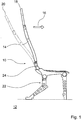
- FIG. 1 shows in a highly schematic side view designed as an aircraft seat passenger seat 10, which is arranged on a floor 12 of an inner cabin, not shown, of an aircraft.
- the passenger seat 10 can also be used in other means of transport, used in buses, railways and ferries.
- the passenger seat 10 is part of a passenger seat row, not shown, of which several are arranged in the same orientation one behind the other in the inner cabin of the aircraft in a conventional manner.
- the passenger seat has a backrest 14, which is adjustable in a normal adjustment of a stable comfort position 20 by moving in a forward direction 16 to a stable normal position 18, and is equipped with a seat structure 22, with the passenger seat 10 in itself known manner is fixed to the floor 12 of the inner cabin.
- An adjustment of the backrest 14 takes place as a rotational movement about a bearing pin 24, which is connected to a seat divider 26 of the seat structure 22 and arranged perpendicular to the forward direction 16.
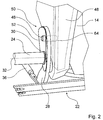
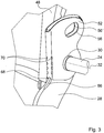
- the passenger seat 10 is equipped with a seat device which comprises a support element 28 arranged on one side of the backrest 14 (FIG. Fig. 2 and 3 ).
- the support element 28 is provided for coupling the backrest 14 to the seat structure 22 and serves to support the backrest 14 in the normal position 18 against the seat structure 22.
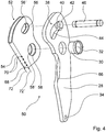
- the support element 28 comprises a bearing element 30 configured as a bearing bush for receiving the bearing journal 24 with a bearing axis 32 for rotatably supporting the backrest 14 about the bearing axis 32 (FIG. Fig. 4 ).
- the support member 28 is provided with a through hole 34 which serves to couple the support member 28 to a gas spring 36 which is provided to assist movement of the seat back 14 from the comfort position 20 to the normal position 18 in a manner known per se ( Fig. 2 ).
- the support element 28 is equipped with a slot unit 38 ( Fig. 4 ) disposed in a radial direction with respect to the bearing axis 32.
- the oblong hole unit 38 comprises a locking element 40 designed as a web, which divides the oblong hole unit 38 into a smaller section 42 and a larger section 44, the smaller section 42 of the oblong hole unit 38 being provided for receiving a coupling element 46 of the seat device formed as a pin.
- the securing element 40 is intended to limit movement of the backrest 14 within the normal adjustment range in the forward direction 16.
- the coupling element 46 is firmly connected to a U-shaped frame element 48 of the backrest 14 ( Fig. 2 and 3 ), so that during a movement of the backrest 14 in the normal adjustment both the backrest 14 and the support member 28 are pivoted about the bearing axis 32.
- the seat device has an energy absorption unit 50, which is provided for receiving kinetic energy in the event of an impact event.
- the energy absorption unit 50 comprises the support element 28 and is equipped with an energy absorption element 52 formed separately from the support element 28 (FIG. Fig. 4 ).
- the support element 28 and the energy absorption element 52 cooperate in the event of an impact event to reduce an impact energy in a manner which will be described in more detail below.
- the energy absorbing element 52 consists of a thin sheet of stainless steel ( Fig. 4 ). It has in a sectional plane which is parallel to the floor 12 of the inner cabin, a U-shaped profile and is further provided with a plurality of symmetrically arranged to a front edge 54 of the energy absorbing element 52 through holes 56, 56 ', 58, 58'.
- the through holes 56, 56 ' are formed as elongated holes whose center lines are aligned with respect to the bearing axis 32 in a radial direction.
- the U-shaped profile of the energy absorbing member 52 engages an upper end of the support member 28 with the lower through holes 58, 58 'of the energy absorbing member 52 aligned with the bearing member 30 of the support member 28 and the two through holes 56 disposed in an upper portion of the energy absorbing member 52; 56 'release the smaller section 42 of the slot unit 38 of the support member 28 for receiving the coupling member 46.
- the bearing bush of the support member 28 is freely rotatable ( Fig. 4 ).
- the energy absorption element 52 is also pivoted about the bearing axis 32.
- the energy absorption unit 50 has one of them as a long-term extinguisher trained delay holes 56, 56 'formed delay element, which delays in the case of the impact event after exceeding the normal adjustment range of the backrest 14, the reduction of the impact energy by a predetermined period of time.
- a entrainment movement of the energy absorbing element 52 through the coupling element 46 is delayed after exceeding the normal adjustment range of the backrest 14 in a movement of the backrest 14 in the forward direction 16, since the coupling element 46 must first reach a forward direction 16 facing edge of the through holes 56, 56 ', before the energy absorbing element 52 can be carried by the coupling element 46.
- a first force introduction path 60 of a force acting on the backrest 14 in the forward direction 16 is shown in the seat structure 22 within the normal adjustment range of the backrest 14. It extends from coupling points 64 of the U-shaped frame member 48 of the backrest 14 with the coupling elements 46 of the seat apparatus (FIG. Fig. 2 ) along the support member 28, further on the gas spring 36, which is hinged at its end facing away from the support member 28 to the seat structure 22, and terminates in the seat structure 22.
- the energy absorption element 52 is in this mode by the backrest 14 in terms of strength unloaded.
- the web-formed securing element 40 is intended to break the larger section 44 of the slot unit 38 of the support member 28 for movement of the pin Releasing the coupling element 46 of the seat device and to allow exceeding the normal adjustment of the backrest 14 in the forward direction 16 ( Fig. 4 ).
- a further forward in the direction 16 advancing movement of the backrest 14 designed as a pin coupling element 46 of the seat device to the forward direction 16 facing edge of the through holes 56, 56 'proposes.
- the coupling element 46 exerts a torque about the bearing axis 32 on the energy absorbing element 52 and causes a clamping of the energy absorbing element 52 with a cutting edge formed as a centering element 66 of the support member 28 (FIG. Fig. 8 ).
- the delay element is a time delay of the entrainment movement of the energy absorbing element 52 by causes the coupling element 46, which in the case of the impact event, a collision of a passenger on a back of a backrest 14 of the passenger arranged passenger seat 10 timed and thus can influence an impact position on the back of the backrest 14.
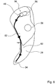
- a second force introduction path 62 of the force acting on the backrest 14 exists in the seat structure 22 (FIG. Fig. 8 ).
- the second force introduction path 62 unlike the first force introduction path 60 in the operating state of the normal adjustment range of the backrest 14, extends from the coupling points 64 of the U-shaped frame element 48 of the backrest 14 (FIG. Fig. 2 and 3 ) with the coupling elements 46 of the seat device formed as pins along the front edge 54 of the energy absorbing element 52, opens at a lower end of the front edge 54 of the energy absorbing element 52 in the support member 28, extends over the gas spring 36 and ends in the seat structure 22.
- the energy absorbing element 52 When exceeding the normal adjustment of the backrest 14, the energy absorbing element 52 causes a deflection of a force flow from the first force introduction path 60 to the second force introduction path 62.
- the energy absorption element 52 is in this mode by the backrest 14 in terms of power loaded, since the coupling element 46 of the seat device, a torque about the bearing axis 32 on the Energyabsorptionselement 52 exerts.
- the energy absorbing element 52 is intended to absorb energy when it exceeds the normal adjustment range of the backrest 14 by plastic deformation. The absorbed energy is removed from a kinetic energy of the backrest 14 and converted into heat by the plastic deformation of the energy absorption element 52.
- the energy absorbing element 52 has a plurality of weakening elements 70 formed as holes (FIG. Fig. 4 and Fig. 5 ), which are arranged in two parallel to the front edge 54 of the energy absorption element 52 rows and are provided to set 62 predetermined breaking directions 72, 72 'in the case of the generated by exceeding the normal adjustment range of the backrest 14 second force introduction path.
- Fig. 6 For example, an energy absorbing element 52 plastically deformed by an impact event is shown in a passenger seat.
- the energy absorption element 52 In the area of a contact point between the lower region of the front edge 54 of the energy absorption element 52 and the support member 28, the energy absorption element 52 along the predetermined breaking directions 72, 72 'torn open and widened to the outside, so that the backrest 14 remains freely movable and adjusted with a small force in the normal position 18 can.
- the centering element 66 of the support element 52 designed as a cutting edge and a corresponding centering element 68 formed as a round notch in the lower region of the front edge 54 of the energy absorption element 52, which is intended to center the energy absorption element 52 in the event of exceeding the normal adjustment range of the backrest 14, a controlled deformation of the energy absorbing element 52 can be achieved ( Fig. 4 and Fig. 5 ).
- a deformation energy absorbed by the energy absorbing element 52 after exceeding the normal adjustment range of the backrest 14 is substantially proportional to a displacement distance traveled by the energy absorbing element 52 Fig. 6 can be equated to a rolled-up track, so that an energy absorption by the energy absorbing element 52 is uniform and power surges can be advantageously avoided by sudden acceleration in the energy intake.
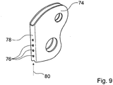
- FIG. 9 another embodiment of an energy absorbing element 74 is shown.
- the energy absorption element 74 has attenuation elements 76 formed as holes, which are arranged in a row parallel to a front edge 78 of the energy absorption element 74 and intended to define a single predetermined breaking direction 80 in the event of a second force introduction path generated by exceeding a normal adjustment range of a backrest.
Landscapes
- Engineering & Computer Science (AREA)
- Aviation & Aerospace Engineering (AREA)
- Transportation (AREA)
- Mechanical Engineering (AREA)
- Seats For Vehicles (AREA)
Description
- Im Falle eines Aufprallereignisses bei Fahrzeugen, die zur Beförderung von Passagieren vorgesehen und zu diesem Zweck mit Fahrgastsitzen ausgestattet sind, ist es von besonderer Bedeutung, die bei der plötzlichen Verzögerung frei werdende Energie von den Passagieren abzulenken.
- Aus dem
US-Patent 4,349,167 ist bereits ein Fahrgastsitz bekannt, der mehrere Energieabsorptionselemente aufweist. - Weitere Fahrgastsitze mit Energieabsorptionselementen sind aus den Dokumenten
GB 2418 843 A GB 2 450 612 A DE 199 31 894 A1 ,WO 97/29923 A1 DE 198 07 581 A1 bekannt. - Der vorliegenden Erfindung liegt insbesondere die Aufgabe zugrunde, eine einfache, kostengünstige und platzsparende Lösung zur Absorption von Bewegungsenergie im Falle eines Aufprallereignisses bei Fahrzeugen bereitzustellen.
- Diese Aufgabe wird durch eine Sitzvorrichtung eines Fahrgastsitzes gemäß dem Patentanspruch 1 gelöst. Weitere vorteilhafte Weiterbildungen der Erfindung können den Unteransprüchen entnommen werden.
- Die Erfindung geht aus von einer Sitzvorrichtung eines Fahrgastsitzes, der eine Rückenlehne, die in einem normalen Verstellbereich von zumindest einer stabilen Komfortposition durch eine Bewegung in eine Vorwärtsrichtung bis zu einer Normalposition verstellbar ist, und eine Sitzstruktur zur Befestigung des Fahrgastsitzes an einem Boden aufweist, mit zumindest einem Stützelement zur Kopplung der Rückenlehne an die Sitzstruktur und mit zumindest einer Energieabsorptionseinheit zur Aufnahme von Bewegungsenergie im Falle eines Aufprallereignisses, wobei die Energieabsorptionseinheit das zumindest eine Stützelement und ein von dem Stützelement separat ausgebildetes Energieabsorptionselement umfasst und das zumindest eine Stützelement und das Energieabsorptionselement im Falle des Aufprallereignisses zum Abbau einer Aufprallenergie zusammenwirken, wobei das Energieabsorptionselement dazu vorgesehen ist, bei einer Überschreitung des normalen Verstellbereichs der Rückenlehne durch plastische Verformung Energie aufzunehmen, und wobei das zumindest eine Stützelement zumindest ein Lagerelement mit einer Lagerachse zur drehbaren Lagerung der Rückenlehne aufweist, und mit zumindest einem Kopplungselement umfasst, das bei der Überschreitung des normalen Verstellbereichs der Rückenlehne ein Drehmoment um die Lagerachse auf das zumindest eine Energieabsorptionselement ausübt.
- Es wird vorgeschlagen, dass das Energieabsorptionselement das Stützelement zumindest teilweise umgreift, wobei das bei der Überschreitung des normalen Verstellbereichs der Rückenlehne von dem Kopplungselement auf das zumindest eine Energieabsorptionselement ausgeübte Drehmoment um die Lagerachse eine Klemmung des Energieabsorptionselements bewirkt, wobei das Energieabsorptionselement zumindest ein Zentrierelement umfasst, das dazu vorgesehen ist, das Energieabsorptionselement im Falle der Überschreitung des normalen Verstellbereichs der Rückenlehne zu zentrieren , wobei das Stützelement ein zu dem Zentrierelement des Energieabsorptionselements korrespondierendes Zentrierelement aufweist. Unter "separat" soll in diesem Zusammenhang insbesondere verstanden werden, dass das Stützelement und das Energieabsorptionselement zumindest zweiteilig ausgebildet sind. Dadurch kann eine einfache und platzsparende Lösung zur Absorption von Bewegungsenergie im Falle des Aufprallereignisses bei Fahrzeugen bereitgestellt werden. Durch das separat ausgebildete Energieabsorptionselement der Energieabsorptionseinheit kann darüber hinaus eine ungehinderte Bewegung der Rückenlehne im normalen Verstellbereich und eine Energieübertragung von Bewegungsenergie auf das Energieabsorptionselement nur im Falle des Aufprallereignisses ermöglicht werden. Die Sitzvorrichtung ist ferner mit Vorteil bei bereits bestehenden Fahrgastsitzen nachrüstbar.
- Wenn innerhalb des normalen Verstellbereichs der Rückenlehne ein erster Krafteinleitungsweg einer auf die Rückenlehne wirkenden Kraft in die Sitzstruktur existiert und bei einer Überschreitung des normalen Verstellbereichs der Rückenlehne ein zweiter Krafteinleitungsweg einer auf die Rückenlehne wirkenden Kraft in die Sitzstruktur existiert und das Energieabsorptionselement eine Umlenkung eines Kraftflusses vom ersten Krafteinleitungsweg zum zweiten Krafteinleitungsweg bewirkt, kann eine effektive Umlenkung der Kraftwirkung durch das Energieabsorptionselement zur Absorption von Energie erreicht werden.
- Des Weiteren wird vorgeschlagen, dass das Energieabsorptionselement zumindest ein Schwächungselement zur Schwächung der mechanischen Festigkeit aufweist. Durch das zumindest eine Schwächungselement kann eine einfache Anpassung der mechanischen Festigkeit an im Falle des Aufprallereignisses zu erwartende Kräfte auf die Rückenlehne zur Optimierung einer Energieabsorption durch das Energieabsorptionselement erzielt werden.
- Wenn das Energieabsorptionselement zumindest zwei Schwächungselemente aufweist, die dazu vorgesehen sind, im Falle des durch Überschreitung des normalen Verstellbereichs der Rückenlehne erzeugten zweiten Krafteinleitungswegs eine Sollbruchrichtung festzulegen, kann eine kontrollierte Verformung des Energieabsorptionselements erreicht werden. Besonders vorteilhaft kann das Energieabsorptionselement Schwächungselemente aufweisen, die zumindest zwei Sollbruchrichtungen festlegen, die vorzugsweise parallel verlaufen, wodurch im Falle des Aufprallereignisses eine kontrollierte Aufteilung des Energieabsorptionselement in mehrere Abschnitte ermöglicht wird. Wenn die Aufteilung in mehrere Abschnitte mit einer Vergrößerung von Abständen der Einzelabschnitte verbunden ist, kann insbesondere eine bestehende Sicherheitsvorschrift des Flugverkehrs, nach der nach einem Eintritt des Aufprallereignisses eine leichte Verstellung der Rückenlehne in die Normalposition gewährleistet sein muss, besonders einfach erfüllt werden.
- Ganz besonders vorteilhaft ist es, wenn das Zentrierelement des Stützelements einen keilförmigen Querschnitt aufweist, da bei entsprechender Ausgestaltung neben einer Zentrierungswirkung eine effektive Schneidwirkung des Stützelements ermöglicht werden kann, die eine Aufnahme einer großen Energiemenge durch das Energieabsorptionselement ermöglicht.
- Weiterhin wird vorgeschlagen, dass die Energieabsorptionseinheit zumindest ein Sicherungselement aufweist, das dazu vorgesehen ist, eine Bewegung der Rückenlehne innerhalb des normalen Verstellbereichs in zumindest einer Richtung zu begrenzen und bei einer Überschreitung einer vorbestimmten Kraftwirkung auf die Rückenlehne in zumindest einer Richtung eine Überschreitung des Verstellbereichs der Rückenlehne zu ermöglichen. Vorteilhaft kann dadurch die Bewegung der Rückenlehne in einem normalen Betriebsmodus des Fahrgastsitzes innerhalb des normalen Verstellbereichs kontrolliert werden, und im Falle des Aufprallereignisses kann durch eine kontrollierte Überschreitung des Verstellbereichs der Rückenlehne Bewegungsenergie von der Rückenlehne auf die Energieabsorptionseinheit übertragen werden.
- Wenn eine nach einer Überschreitung des normalen Verstellbereichs der Rückenlehne von dem Energieabsorptionselement aufgenommene Verformungsenergie im Wesentlichen proportional zu einer von dem Energieabsorptionselement zurückgelegten Verschiebungsstrecke ist, können vorteilhaft plötzliche Beschleunigungen während der Energieabsorption im Energieabsorptionselement vermieden und ein gleichmäßiger Energieabbau der Bewegungsenergie der Rückenlehne erreicht werden. Unter "im Wesentlichen linear" soll in diesem Zusammenhang insbesondere verstanden werden, dass ein Proportionalitätsfaktor zwischen der von dem Energieabsorptionselement aufgenommenen Energie und der vom Energieabsorptionselement zurückgelegten Verschiebungsstrecke um weniger als 50% variiert.
- Besonders vorteilhaft ist es unter fertigungstechnischen Gesichtspunkten, wenn das Energieabsorptionselement in zumindest einer Schnittebene ein U-förmiges Profil aufweist, da bei entsprechender Ausgestaltung durch Einsatz von Umbiege- und Stanztechnik eine einfache und kostengünstige Fertigung des Energieabsorptionselements ermöglicht werden kann. Durch die U-förmige Formgebung kann zugleich eine günstige Krafteinleitung in das Energieabsorptionselement erreicht werden.
- Wenn das Energieabsorptionselement im Wesentlichen aus Edelstahl besteht, können vorteilhaft große Energiebeträge absorbiert und durch den Einsatz bekannter Verformungstechnik kostengünstige Lösungen bereitgestellt werden. Unter "im Wesentlichen" soll in diesem Zusammenhang insbesondere verstanden werden, dass das Energieabsorptionselement vorzugsweise zu mehr als 50% und, besonders vorteilhaft, zu mehr als 70% aus Edelstahl besteht.
- Weitere Vorteile ergeben sich aus der folgenden Zeichnungsbeschreibung. In der Zeichnung sind Ausführungsbeispiele der Erfindung dargestellt. Die Beschreibung und die Ansprüche enthalten zahlreiche Merkmale in Kombination. Der Fachmann wird die Merkmale zweckmäßigerweise auch einzeln betrachten und zu sinnvollen weiteren Kombinationen zusammenfassen.
- Es zeigen:
- Fig. 1
- eine stark schematisierte Seitenansicht eines Fahrgastsitzes,
- Fig. 2
- eine Sitzvorrichtung eines Fahrgastsitzes mit einer Energieabsorptionseinheit im eingebauten Zustand in einer rückseitigen Ansicht mit einer Rückenlehne im normalen Verstellbereich,
- Fig. 3
- die Sitzvorrichtung gemäß der
Fig. 2 in einer Ansicht von schräg vorn, - Fig. 4
- eine Explosionsansicht einer Energieabsorptionseinheit,
- Fig. 5
- eine Energieabsorptionseinheit in einem montierten Zustand,
- Fig. 6
- eine Sitzvorrichtung eines Fahrgastsitzes mit einer Energieabsorptionseinheit im eingebauten Zustand, nach einer Überschreitung des normalen Verstellbereichs der Rückenlehne,
- Fig. 7
- einen ersten Krafteinleitungsweg im normalen Verstellbereich der Rückenlehne,
- Fig. 8
- einen zweiten Krafteinleitungsweg nach einer Überschreitung des normalen Verstellbereichs der Rückenlehne und
- Fig. 9
- ein weiteres Ausführungsbeispiel eines Energieabsorptionselements.
-
Figur 1 zeigt in einer stark schematisierten Seitenansicht einen als Flugzeugsitz ausgebildeten Fahrgastsitz 10, der auf einem Boden 12 einer nicht näher dargestellten Innenkabine eines Flugzeugs angeordnet ist. Der Fahrgastsitz 10 kann aber auch in anderen Transportmitteln, etwa in Bussen, Eisenbahnen und Fährschiffen, verwendet werden. Der Fahrgastsitz 10 ist Teil einer nicht näher dargestellten Fahrgastsitzreihe, von denen mehrere in gleicher Ausrichtung hintereinander in der Innenkabine des Flugzeugs in an sich bekannter Weise angeordnet sind. - Der Fahrgastsitz weist eine Rückenlehne 14 auf, die in einem normalen Verstellbereich von einer stabilen Komfortposition 20 durch eine Bewegung in eine Vorwärtsrichtung 16 bis zu einer stabilen Normalposition 18 verstellbar ist, und ist mit einer Sitzstruktur 22 ausgestattet, mit der der Fahrgastsitz 10 in an sich bekannter Weise an dem Boden 12 der Innenkabine befestigt ist. Eine Verstellung der Rückenlehne 14 erfolgt als Drehbewegung um einen Lagerzapfen 24, der mit einem Sitzteiler 26 der Sitzstruktur 22 verbunden und senkrecht zu der Vorwärtsrichtung 16 angeordnet ist.
- Der Fahrgastsitz 10 ist mit einer Sitzvorrichtung ausgestattet, die ein an einer Seite der Rückenlehne 14 angeordnetes Stützelement 28 umfasst (
Fig. 2 und3 ). Das Stützelement 28 ist zur Kopplung der Rückenlehne 14 an die Sitzstruktur 22 vorgesehen und dient dazu, die Rückenlehne 14 in der Normalposition 18 gegen die Sitzstruktur 22 abzustützen. Das Stützelement 28 umfasst ein als Lagerbuchse zur Aufnahme des Lagerzapfens 24 ausgebildetes Lagerelement 30 mit einer Lagerachse 32 zur drehbaren Lagerung der Rückenlehne 14 um die Lagerachse 32 (Fig. 4 ). An einem seiner Enden ist das Stützelement 28 mit einem Durchgangsloch 34 versehen, das zur Ankopplung des Stützelements 28 an eine Gasdruckfeder 36 dient, die zur Unterstützung einer Bewegung der Rückenlehne 14 von der Komfortposition 20 in die Normalposition 18 in an sich bekannter Weise vorgesehen ist (Fig. 2 ). - An einem oberen Ende ist das Stützelement 28 mit einer Langlocheinheit 38 ausgestattet (
Fig. 4 ), die in einer in Bezug auf die Lagerachse 32 radialen Richtung angeordnet ist. Die Langlocheinheit 38 umfasst ein als Steg ausgebildetes Sicherungselement 40, das die Langlocheinheit 38 in eine kleinere Sektion 42 und eine größere Sektion 44 unterteilt, wobei die kleinere Sektion 42 der Langlocheinheit 38 zur Aufnahme eines als Zapfen ausgebildeten Kopplungselements 46 der Sitzvorrichtung vorgesehen ist. Das Sicherungselement 40 ist dazu vorgesehen, eine Bewegung der Rückenlehne 14 innerhalb des normalen Verstellbereichs in der Vorwärtsrichtung 16 zu begrenzen. Das Kopplungselement 46 ist fest mit einem U-förmigen Rahmenelement 48 der Rückenlehne 14 verbunden (Fig. 2 und3 ), so dass bei einer Bewegung der Rückenlehne 14 im normalen Verstellbereich sowohl die Rückenlehne 14 als auch das Stützelement 28 um die Lagerachse 32 geschwenkt werden. - Ferner weist die Sitzvorrichtung eine Energieabsorptionseinheit 50 auf, die zur Aufnahme von Bewegungsenergie im Falle eines Aufprallereignisses vorgesehen ist. Die Energieabsorptionseinheit 50 umfasst das Stützelement 28 und ist mit einem von dem Stützelement 28 separat ausgebildeten Energieabsorptionselement 52 ausgestattet (
Fig. 4 ). - Das Stützelement 28 und das Energieabsorptionselement 52 wirken im Falle des Aufprallereignisses zum Abbau einer Aufprallenergie in einer Weise zusammen, die im Folgenden näher beschrieben wird.
- Das Energieabsorptionselement 52 besteht aus einem dünnen Blech aus Edelstahl (
Fig. 4 ). Es weist in einer Schnittebene, die parallel zum Boden 12 der Innenkabine liegt, ein U-förmiges Profil auf und ist ferner mit mehreren, symmetrisch zu einer Vorderkante 54 des Energieabsorptionselements 52 angeordneten Durchgangslöchern 56, 56', 58, 58' ausgestattet. Die Durchgangslöcher 56, 56' sind als Langlöcher ausgebildet, deren Mittellinien in Bezug auf die Lagerachse 32 in einer radialen Richtung ausgerichtet sind. In einem betriebsbereiten Zustand (Fig. 5 ) umgreift das U-förmige Profil des Energieabsorptionselements 52 ein oberes Ende des Stützelements 28, wobei die unteren Durchgangslöcher 58, 58' des Energieabsorptionselements 52 mit dem Lagerelement 30 des Stützelements 28 fluchten und die zwei in einem oberen Teil des Energieabsorptionselements 52 angeordneten Durchgangslöcher 56, 56' die kleinere Sektion 42 der Langlocheinheit 38 des Stützelements 28 zur Aufnahme des Kopplungselements 46 freigeben. - In den beiden unteren Durchgangslöchern 58, 58' des Energieabsorptionselements 52 ist die Lagerbuchse des Stützelements 28 frei drehbar (
Fig. 4 ). Durch das als Zapfen ausgebildete Kopplungselement 46 der Sitzvorrichtung, das sowohl die kleinere Sektion 42 der Langlocheinheit 38 des Stützungselements 28 als auch die beiden im oberen Teil des Energieabsorptionselements 52 angeordneten Durchgangslöcher 56, 56' durchdringt, wird bei einer Bewegung im normalen Verstellbereich der Rückenlehne 14 neben der Rückenlehne 14 und dem Stützelement 28 auch das Energieabsorptionselement 52 um die Lagerachse 32 geschwenkt. Die Energieabsorptionseinheit 50 weist ein von den als Langlöeher ausgebildeten Durchgangslöchern 56, 56' gebildetes Verzögerungselement auf, das im Falle des Aufprallereignisses nach einer Überschreitung des normalen Verstellbereichs der Rückenlehne 14 den Abbau der Aufprallenergie um eine vorbestimmte Zeitspanne verzögert. Eine Mitnahmebewegung des Energieabsorptionselements 52 durch das Kopplungselement 46 erfolgt nach einer Überschreitung des normalen Verstellbereichs der Rückenlehne 14 in einer Bewegung der Rückenlehne 14 in Vorwärtsrichtung 16 verzögert, da das Kopplungselement 46 zunächst einen der Vorwärtsrichtung 16 zugewandten Rand der Durchgangslöcher 56, 56' erreichen muss, bevor das Energieabsorptionselement 52 von dem Kopplungselement 46 mitgeführt werden kann. - In der
Fig. 7 ist ein innerhalb des normalen Verstellbereichs der Rückenlehne 14 existierender erster Krafteinleitungsweg 60 einer auf die Rückenlehne 14 in der Vorwärtsrichtung 16 wirkenden Kraft in die Sitzstruktur 22 dargestellt. Er verläuft von Kopplungsstellen 64 des U-förmigen Rahmenelements 48 der Rückenlehne 14 mit den als Zapfen ausgebildeten Kopplungselementen 46 der Sitzvorrichtung (Fig. 2 ) entlang des Stützelements 28, weiter über die Gasdruckfeder 36, die an ihrem dem Stützelement 28 abgewandten Ende an die Sitzstruktur 22 angelenkt ist, und endet in der Sitzstruktur 22. Das Energieabsorptionselement 52 ist in diesem Betriebszustand durch die Rückenlehne 14 kräftemäßig unbelastet. - Bei Überschreitung einer vorbestimmten, in Vorwärtsrichtung wirkenden Kraft auf die Rückenlehne 14, beispielsweise im Falle des Aufprallereignisses, ist das als Steg ausgebildete Sicherungselement 40 dazu vorgesehen, zu brechen, die größere Sektion 44 der Langlocheinheit 38 des Stützelements 28 für eine Bewegung des als Zapfen ausgebildeten Kopplungselements 46 der Sitzvorrichtung freizugeben und eine Überschreitung des normalen Verstellbereichs der Rückenlehne 14 in der Vorwärtsrichtung 16 zu ermöglichen (
Fig. 4 ). Bei einer weiter in Vorwärtsrichtung 16 voranschreitenden Bewegung der Rückenlehne 14 schlägt das als Zapfen ausgebildete Kopplungselement 46 der Sitzvorrichtung an den der Vorwärtsrichtung 16 zugewandten Rand der Durchgangslöcher 56, 56' an. In diesem Betriebszustand übt das Kopplungselement 46 ein Drehmoment um die Lagerachse 32 auf das Energieabsorptionselement 52 aus und bewirkt eine Klemmung des Energieabsorptionselements 52 mit einem als Schneidkante ausgebildeten Zentrierelement 66 des Stützelements 28 (Fig. 8 ). Durch das Verzögerungselement wird eine zeitliche Verzögerung der Mitnahmebewegung des Energieabsorptionselements 52 durch das Kopplungselement 46 bewirkt, wodurch sich im Falle des Aufprallereignisses ein Aufprall eines Fahrgastes auf eine Rückseite einer Rückenlehne 14 des vor dem Fahrgast angeordneten Fahrgastsitzes 10 zeitlich steuern und damit eine Aufprallposition auf der Rückseite der Rückenlehne 14 beeinflussen lässt. - Nach der Überschreitung des normalen Verstellbereichs existiert ein zweiter Krafteinleitungsweg 62 der auf die Rückenlehne 14 wirkenden Kraft in die Sitzstruktur 22 (
Fig. 8 ). Der zweite Krafteinleitungsweg 62 verläuft, abweichend von dem ersten Krafteinleitungsweg 60 im Betriebszustand des normalen Verstellbereichs der Rückenlehne 14, von den Kopplungsstellen 64 des U-förmigen Rahmenelements 48 der Rückenlehne 14 (Fig. 2 und3 ) mit den als Zapfen ausgebildeten Kopplungselementen 46 der Sitzvorrichtung entlang der Vorderkante 54 des Energieabsorptionselements 52, mündet an einem unteren Ende der Vorderkante 54 des Energieabsorptionselements 52 in das Stützelement 28, verläuft über die Gasdruckfeder 36 und endet in der Sitzstruktur 22. Bei der Überschreitung des normalen Verstellbereichs der Rückenlehne 14 bewirkt das Energieabsorptionselement 52 eine Umlenkung eines Kraftflusses vom ersten Krafteinleitungsweg 60 zum zweiten Krafteinleitungsweg 62. Das Energieabsorptionselement 52 ist in diesem Betriebszustand durch die Rückenlehne 14 kräftemäßig belastet, da das Kopplungselement 46 der Sitzvorrichtung ein Drehmoment um die Lagerachse 32 auf das Energieabsorptionselement 52 ausübt. - Das Energieabsorptionselement 52 ist dazu vorgesehen, bei einer Überschreitung des normalen Verstellbereichs der Rückenlehne 14 durch plastische Verformung Energie aufzunehmen. Die aufgenommene Energie wird einer Bewegungsenergie der Rückenlehne 14 entzogen und durch die plastische Verformung des Energieabsorptionselements 52 in Wärme umgewandelt.
- Zur Schwächung der mechanischen Festigkeit weist das Energieabsorptionselement 52 mehrere als Löcher ausgebildete Schwächungselemente 70 auf (
Fig. 4 undFig. 5 ), die in zwei zur Vorderkante 54 des Energieabsorptionselements 52 parallelen Reihen angeordnet und dazu vorgesehen sind, im Falle des durch Überschreitung des normalen Verstellbereichs der Rückenlehne 14 erzeugten zweiten Krafteinleitungswegs 62 Sollbruchrichtungen 72, 72' festzulegen. InFig. 6 ist ein durch ein Aufprallereignis plastisch verformtes Energieabsorptionselement 52 in einem Fahrgastsitz dargestellt. Im Bereich einer Kontaktstelle zwischen dem unteren Bereich der Vorderkante 54 des Energieabsorptionselements 52 und dem Stützelement 28 ist das Energieabsorptionselement 52 entlang der Sollbruchrichtungen 72, 72' aufgerissen und nach außen aufgeweitet, so dass die Rückenlehne 14 frei beweglich bleibt und mit einem geringem Kraftaufwand in die Normalposition 18 verstellt werden kann. Durch das als Schneidkante ausgebildete Zentrierelement 66 des Stützelements 52 und ein korrespondierendes, als Rundkerbe ausgebildetes Zentrierelement 68 im unteren Bereich der Vorderkante 54 des Energieabsorptionselements 52, das dazu vorgesehen ist, das Energieabsorptionselement 52 im Falle der Überschreitung des normalen Verstellbereichs der Rückenlehne 14 zu zentrieren, kann eine kontrollierte Verformung des Energieabsorptionselements 52 erreicht werden (Fig. 4 undFig. 5 ). - Durch die einem Aufrollen ähnelnde Verformung der Vorderkante 54 des Energieabsorptionselements 52 ist eine nach einer Überschreitung des normalen Verstellbereichs der Rückenlehne 14 von dem Energieabsorptionselement 52 aufgenommene Verformungsenergie im Wesentlichen proportional zu einer von dem Energieabsorptionselement 52 zurückgelegten Verschiebungsstrecke, die in
Fig. 6 einer aufgerollten Strecke gleichgesetzt werden kann, so dass eine Energieaufnahme durch das Energieabsorptionselement 52 gleichmäßig erfolgt und Kraftstöße durch plötzliche Beschleunigungen bei der Energieaufnahme vorteilhaft vermieden werden können. - In der
Fig. 9 ist ein weiteres Ausführungsbeispiel eines Energieabsorptionselements 74 dargestellt. Im Unterschied zum Ausführungsbeispiel derFig. 1 bis 8 weist das Energieabsorptionselement 74 als Löcher ausgebildete Schwächungselemente 76 auf, die in einer zu einer Vorderkante 78 des Energieabsorptionselements 74 parallelen Reihe angeordnet und dazu vorgesehen sind, im Falle eines durch eine Überschreitung eines normalen Verstellbereichs einer Rückenlehne erzeugten zweiten Krafteinleitungswegs eine einzige Sollbruchrichtung 80 festzulegen.Bezugszeichen 10 Fahrgastsitz 52 Energieabsorptionselement 12 Boden 54 Vorderkante 14 Rückenlehne 56 Durchgangsloch 16 Vorwärtsrichtung 58 Durchgangsloch 18 Normalposition 60 Krafteinleitungsweg 20 Komfortposition 62 Krafteinleitungsweg 22 Sitzstruktur 64 Kopplungsstelle 24 Lagerzapfen 66 Zentrierelement 26 Sitzteiler 68 Zentrierelement 28 Stützelement 70 Schwächungselement 30 Lagerelement 72 Sollbruchrichtung 32 Lagerachse 74 Energieabsorptionselement 34 Durchgangsloch 76 Schwächungselement 36 Gasdruckfeder 78 Vorderkante 38 Langlocheinheit 80 Sollbruchrichtung 40 Sicherungselement 42 Sektion 44 Sektion 46 Kopplungselement 48 Rahmenelement 50 Energieabsorptionseinheit
Claims (7)
- Sitzvorrichtung eines Fahrgastsitzes (10), der eine Rückenlehne (14), die in einem normalen Verstellbereich von zumindest einer stabilen Komfortposition (20) durch eine Bewegung in eine Vorwärtsrichtung (16) bis zu einer Normalposition (18) verstellbar ist, und eine Sitzstruktur (22) zur Befestigung des Fahrgastsitzes (10) an einem Boden (12) aufweist, mit zumindest einem Stützelement (28) zur Kopplung der Rückenlehne (14) an die Sitzstruktur (22), mit zumindest einer Energieabsorptionseinheit (50) zur Aufnahme von Bewegungsenergie im Falle eines Aufprallereignisses, wobei die Energieabsorptionseinheit (50) das zumindest eine Stützelement (28) und ein von dem Stützelement (28) separat ausgebildetes Energieabsorptionselement (52; 74) umfasst und das zumindest eine Stützelement (28) und das Energieabsorptionselement (52; 74) im Falle des Aufprallereignisses zum Abbau einer Aufprallenergie zusammenwirken,
wobei
das Energieabsorptionselement (52; 74) dazu vorgesehen ist, bei einer Überschreitung des normalen Verstellbereichs der Rückenlehne (14) durch plastische Verformung Energie aufzunehmen, und
wobei
das zumindest eine Stützelement (28) zumindest ein Lagerelement (30) mit einer Lagerachse (32) zur drehbaren Lagerung der Rückenlehne (14) aufweist, und mit zumindest einem Kopplungselement (46), das bei der Überschreitung des normalen Verstellbereichs der Rückenlehne (14) ein Drehmoment um die Lagerachse (32) auf das zumindest eine Energieabsorptionselement (52; 74) ausübt,
dadurch gekennzeichnet, dass das Energieabsorptionselement (52; 74) das Stützelement (28) zumindest teilweise umgreift, wobei das bei der Überschreitung des normalen Verstellbereichs der Rückenlehne (14) von dem Kopplungselement (46) auf das zumindest eine Energieabsorptionselement (52; 74) ausgeübte Drehmoment um die Lagerachse (32) eine Klemmung des Energieabsorptionselements (52) bewirkt, wobei das Energieabsorptionselement (52; 74) zumindest ein Zentrierelement (68) umfasst, das dazu vorgesehen ist, das Energieabsorptionselement (52; 74) im Falle der Überschreitung des normalen Verstellbereichs der Rückenlehne (14) zu zentrieren, wobei das Stützelement (28) ein zu dem Zentrierelement (68) des Energieabsorptionselements (52, 74) korrespondierendes Zentrierelement (66) aufweist. - Sitzvorrichtung nach Anspruch 1,
dadurch gekennzeichnet, dass
innerhalb des normalen Verstellbereichs der Rückenlehne (14) ein erster Krafteinleitungsweg (60) einer auf die Rückenlehne (14) wirkenden Kraft in die Sitzstruktur (22) existiert und bei einer Überschreitung des normalen Verstellbereichs der Rückenlehne (14) ein zweiter Krafteinleitungsweg (62) einer auf die Rückenlehne (14) wirkenden Kraft in die Sitzstruktur (22) existiert und das Energieabsorptionselement (52; 74) eine Umlenkung eines Kraftflusses vom ersten Krafteinleitungsweg (60) zum zweiten Krafteinleitungsweg (62) bewirkt,
wobei bei Überschreitung einer vorbestimmten, in Vorwärtsrichtung wirkenden Kraft auf die Rückenlehne (14), beispielsweise im Falle des Aufprallereignisses, ein als Steg ausgebildetes Sicherungselement (40) dazu vorgesehen, zu brechen, eine größere Sektion (44) einer Langlocheinheit (38) des Stützelements (28) für eine Bewegung des als Zapfen ausgebildeten Kopplungselements (46) der Sitzvorrichtung freizugeben und eine Überschreitung des normalen Verstellbereichs der Rückenlehne (14) in der Vorwärtsrichtung (16) zu ermöglichen. - Sitzvorrichtung nach Anspruch 1,
dadurch gekennzeichnet, dass
das Kopplungselement (46) der Sitzvorrichtung als Zapfen ausgebildet ist und wobei durch das Kopplungselement (46), das sowohl eine kleinere Sektion (42) einer Langlocheinheit (38) des Stützelements (28) als auch zwei im oberen Teil des Energieabsorptionselements (52) angeordnete Durchgangslöcher (56, 56') durchdringt, bei einer Bewegung im normalen Verstellbereich der Rückenlehne (14) neben der Rückenlehne (14) und dem Stützelement (28) auch das Energieabsorptionselement (52, 74) um die Lagerachse (32) geschwenkt wird. - Sitzvorrichtung nach einem der vorhergehenden Ansprüche,
dadurch gekennzeichnet, dass
das Energieabsorptionselement (52; 74) zumindest ein Schwächungselement (70; 76) zur Schwächung der mechanischen Festigkeit aufweist. - Sitzvorrichtung nach Anspruch 3 und 6,
dadurch gekennzeichnet, dass
das Energieabsorptionselement (52; 74) zumindest zwei Schwächungselemente (70; 76) aufweist, die dazu vorgesehen sind, im Falle des durch Überschreitung des normalen Verstellbereichs der Rückenlehne (14) erzeugten zweiten Krafteinleitungswegs (62) eine Sollbruchrichtung (72; 80) festzulegen. - Sitzvorrichtung nach einem der vorhergehenden Ansprüche, dadurch gekennzeichnet, dass
eine nach einer Überschreitung des normalen Verstellbereichs der Rückenlehne (14) von dem Energieabsorptionselement (52; 74) aufgenommene Verformungsenergie im Wesentlichen proportional zu einer von dem Energieabsorptionselement (52; 74) zurückgelegten Verschiebungsstrecke ist. - Sitzvorrichtung nach einem der vorhergehenden Ansprüche, dadurch gekennzeichnet, dass
das Energieabsorptionselement (52; 74) in zumindest einer Schnittebene ein U-förmiges Profil aufweist.
Applications Claiming Priority (2)
| Application Number | Priority Date | Filing Date | Title |
|---|---|---|---|
| DE102009057880A DE102009057880A1 (de) | 2009-12-11 | 2009-12-11 | Sitzvorrichtung mit Energieabsorptionseinheit |
| PCT/EP2010/007430 WO2011069641A2 (de) | 2009-12-11 | 2010-12-07 | Sitzvorrichtung mit energieabsorptionseinheit |
Publications (2)
| Publication Number | Publication Date |
|---|---|
| EP2509867A2 EP2509867A2 (de) | 2012-10-17 |
| EP2509867B1 true EP2509867B1 (de) | 2019-06-26 |
Family
ID=43992804
Family Applications (1)
| Application Number | Title | Priority Date | Filing Date |
|---|---|---|---|
| EP10798261.3A Not-in-force EP2509867B1 (de) | 2009-12-11 | 2010-12-07 | Sitzvorrichtung mit energieabsorptionseinheit |
Country Status (4)
| Country | Link |
|---|---|
| US (1) | US8864227B2 (de) |
| EP (1) | EP2509867B1 (de) |
| DE (1) | DE102009057880A1 (de) |
| WO (1) | WO2011069641A2 (de) |
Families Citing this family (28)
| Publication number | Priority date | Publication date | Assignee | Title |
|---|---|---|---|---|
| CA2811119C (en) * | 2010-09-14 | 2018-07-10 | Jonathan Evans | Energy absorbing seat for a vehicle |
| DE102012108352A1 (de) * | 2012-09-07 | 2014-03-13 | Recaro Aircraft Seating Gmbh & Co. Kg | Sitzenergieabsorptionsvorrichtung |
| DE102014217506A1 (de) | 2014-09-02 | 2016-03-03 | Brose Fahrzeugteile Gmbh & Co. Kommanditgesellschaft, Coburg | Deformationselement für einen Kraftfahrzeugsitz |
| EP3018011B1 (de) * | 2014-11-06 | 2017-11-29 | Volvo Car Corporation | Verfahren zum betrieb einer sicherheitsvorrichtung in einem fahrzeug |
| US9764844B2 (en) | 2015-04-13 | 2017-09-19 | Encore Seats, Inc. | Aircraft seating assembly |
| JP6560888B2 (ja) * | 2015-04-14 | 2019-08-14 | 株式会社タチエス | 車両用シート |
| US10144515B2 (en) | 2016-04-01 | 2018-12-04 | Encore Seats, Inc. | Aircraft seating assembly and components |
| EP3468833B1 (de) * | 2016-06-14 | 2021-09-01 | HAECO Americas, LLC | Sitzsystem |
| JP6726563B2 (ja) * | 2016-08-09 | 2020-07-22 | 株式会社タチエス | シートフレーム |
| DE102016225818B4 (de) * | 2016-09-21 | 2021-05-12 | Adient Luxembourg Holding S.À R.L. | Längseinsteller sowie Fahrzeugsitz |
| US10414501B2 (en) * | 2017-05-31 | 2019-09-17 | Rockwell Collins, Inc. | Seat back breakover with dynamically triggered actuator |
| US11059587B2 (en) * | 2017-05-31 | 2021-07-13 | B/E Aerospace, Inc. | Seat back decoupler mechanism |
| DE102017117175A1 (de) * | 2017-07-28 | 2019-01-31 | Recaro Aircraft Seating Gmbh & Co. Kg | Flugzeugsitzvorrichtung |
| CN108995816A (zh) * | 2018-07-10 | 2018-12-14 | 湖北文理学院 | 一种集成于座椅主杆的切削式吸能装置 |
| JP7103166B2 (ja) * | 2018-11-02 | 2022-07-20 | トヨタ自動車株式会社 | 車両用シート |
| EP3666654B1 (de) * | 2018-12-13 | 2021-10-06 | B/E Aerospace, Inc. | Sitzlehnenentkopplungsmechanismus |
| CN112009327A (zh) * | 2019-05-29 | 2020-12-01 | 福雷亚自动模式有限公司 | 机动车辆座椅 |
| JP2021008205A (ja) * | 2019-07-01 | 2021-01-28 | 株式会社タチエス | 衝撃吸収装置及び乗物用シート |
| FR3102418B1 (fr) * | 2019-10-25 | 2026-04-10 | Renault Sas | Armature de siège d’un véhicule automobile et siège de véhicule associé |
| US11279488B2 (en) | 2020-02-20 | 2022-03-22 | B/E Aerospace, Inc. | Seat assembly with sacrificial backrest breakover feature |
| DE102020106027A1 (de) * | 2020-03-05 | 2021-09-09 | Zim Flugsitz Gmbh | Fluggastsitz mit Umhausung |
| FR3108566B1 (fr) * | 2020-03-31 | 2022-04-08 | Faurecia Sieges Dautomobile | Système de redressement réactif et dissipatif d’un siège de véhicule |
| FR3111852B1 (fr) * | 2020-06-30 | 2022-08-26 | Faurecia Sieges Dautomobile | Elément de connexion d’un siège de véhicule |
| CN217396315U (zh) * | 2022-03-21 | 2022-09-09 | 延锋国际座椅系统有限公司 | 一种座椅靠背回复吸能机构及座椅 |
| US11975840B2 (en) * | 2022-03-31 | 2024-05-07 | B/E Aerospace, Inc. | Fuse link head impact criteria mitigating device |
| GB2620266A (en) * | 2022-06-07 | 2024-01-03 | Acro Aircraft Seating Ltd | Seat back comprising an energy absorbing device |
| US12429105B2 (en) * | 2022-08-04 | 2025-09-30 | B/E Aerospace, Inc. | Additively manufactured energy absorbing strut device |
| US12269600B2 (en) * | 2023-07-26 | 2025-04-08 | Ami Industries, Inc. | Breakover vehicle operator seat convertible to non-breakover configuration |
Citations (5)
| Publication number | Priority date | Publication date | Assignee | Title |
|---|---|---|---|---|
| WO1997029923A1 (fr) * | 1996-02-16 | 1997-08-21 | Renault | Agencement d'un dispositif de limitation de l'effort de retenue d'un occupant dans un siege de vehicule automobile muni d'une ceinture de securite |
| DE19807581A1 (de) * | 1997-03-07 | 1998-09-10 | Saab Automobile | Verfahren zur Energieaufnahme in einem Kraftfahrzeug, energieaufnehmende Vorrichtung für Fahrzeugsitze sowie Beschlag zur Neigung der Rückenlehne eines Fahrzeugsitzes |
| DE19931894A1 (de) * | 1999-07-08 | 2001-01-11 | Breed Automotive Tech | Fahrzeugsitz |
| GB2418843A (en) * | 2004-10-11 | 2006-04-12 | Autoliv Dev | Recliner mechanism with deformable shock absorbing element |
| GB2450612A (en) * | 2007-06-25 | 2008-12-31 | Imasen Electric Ind | Automobile rear end collision shock absorbing device |
Family Cites Families (12)
| Publication number | Priority date | Publication date | Assignee | Title |
|---|---|---|---|---|
| US4145081A (en) * | 1976-12-22 | 1979-03-20 | Ti Accles & Pollock Limited | Vehicle seat |
| US4349167A (en) | 1979-10-30 | 1982-09-14 | The Boeing Company | Crash load attenuating passenger seat |
| US4394047A (en) * | 1981-06-01 | 1983-07-19 | Uop Inc. | Seat back mounting system |
| US5320308A (en) * | 1991-12-04 | 1994-06-14 | Weber Aircraft, Inc. | Seatback breakover device |
| US5676421A (en) * | 1996-06-20 | 1997-10-14 | Lear Corporation | Vehicle seat energy absorbing mechanism |
| US6053571A (en) * | 1998-07-08 | 2000-04-25 | Trw Vehicle Safety Systems Inc. | Vehicle occupant protection apparatus |
| US6109690A (en) * | 1998-12-18 | 2000-08-29 | Johnson Controls Technology Company | Pivoting seat back |
| US6709053B1 (en) * | 2002-09-30 | 2004-03-23 | Lear Corporation | Vehicle seat assembly with energy managing member |
| US7360832B2 (en) | 2006-01-12 | 2008-04-22 | Tachi-S Co. Ltd. | Impact absorption structure of vehicle seat |
| FR2904796B1 (fr) * | 2006-08-11 | 2008-10-24 | Faurecia Sieges Automobile | Dispositif d'absorption d'energie en cas de choc pour siege de vehicule automobile, siege et vehicule automobile comprenant le dispositif |
| JP5153794B2 (ja) * | 2007-03-22 | 2013-02-27 | オートリブ ディベロップメント エービー | バックレスト支持機構 |
| FR2931403B1 (fr) * | 2008-05-22 | 2010-04-23 | Sicma Aero Seat | Dispositif d'absorption de choc et siege comportant un tel dispositif |
-
2009
- 2009-12-11 DE DE102009057880A patent/DE102009057880A1/de not_active Withdrawn
-
2010
- 2010-12-07 EP EP10798261.3A patent/EP2509867B1/de not_active Not-in-force
- 2010-12-07 WO PCT/EP2010/007430 patent/WO2011069641A2/de not_active Ceased
- 2010-12-07 US US13/514,305 patent/US8864227B2/en active Active
Patent Citations (5)
| Publication number | Priority date | Publication date | Assignee | Title |
|---|---|---|---|---|
| WO1997029923A1 (fr) * | 1996-02-16 | 1997-08-21 | Renault | Agencement d'un dispositif de limitation de l'effort de retenue d'un occupant dans un siege de vehicule automobile muni d'une ceinture de securite |
| DE19807581A1 (de) * | 1997-03-07 | 1998-09-10 | Saab Automobile | Verfahren zur Energieaufnahme in einem Kraftfahrzeug, energieaufnehmende Vorrichtung für Fahrzeugsitze sowie Beschlag zur Neigung der Rückenlehne eines Fahrzeugsitzes |
| DE19931894A1 (de) * | 1999-07-08 | 2001-01-11 | Breed Automotive Tech | Fahrzeugsitz |
| GB2418843A (en) * | 2004-10-11 | 2006-04-12 | Autoliv Dev | Recliner mechanism with deformable shock absorbing element |
| GB2450612A (en) * | 2007-06-25 | 2008-12-31 | Imasen Electric Ind | Automobile rear end collision shock absorbing device |
Also Published As
| Publication number | Publication date |
|---|---|
| WO2011069641A3 (de) | 2011-10-13 |
| DE102009057880A1 (de) | 2011-06-16 |
| US20130049416A1 (en) | 2013-02-28 |
| US8864227B2 (en) | 2014-10-21 |
| EP2509867A2 (de) | 2012-10-17 |
| WO2011069641A2 (de) | 2011-06-16 |
Similar Documents
| Publication | Publication Date | Title |
|---|---|---|
| EP2509867A2 (de) | Sitzvorrichtung mit energieabsorptionseinheit | |
| EP2706010B1 (de) | Sitzenergieabsorptionsvorrichtung | |
| DE69706597T2 (de) | Schienenfahrzeug mit einem Fahrerstand, der eine energieaufnehmende Struktur mit progressiver Verformung aufweist | |
| DE10163890B4 (de) | Kopfstützenanordnung | |
| DE112007001883T5 (de) | Vorrichtung zum Absorbieren von Energie bei einem Aufprall für einen Kraftfahrzeugsitz, Sitz und Fahrzeug mit solch einer Vorrichtung | |
| DE102007018715A1 (de) | Fahrzeugsitz | |
| EP3164331B1 (de) | Flugzeugsitzvorrichtung | |
| DE102012004682A1 (de) | Schutzeinrichtung für eines Karosserie eines Personenkraftwagens | |
| DE102013104748A1 (de) | Verstellanordnung für einen Kraftfahrzeugsitz | |
| EP2070761A2 (de) | Getriebebaueinheit einer Verstelleinrichtung eines Kraftfahrzeugs | |
| WO2003095291A1 (de) | Anbindung für ein fahrerhaus | |
| DE112008001976B4 (de) | Einheit zum Absorbieren von Energie mit zwei Absorptionsvorrichtungen | |
| EP4053017B1 (de) | Energieabsorptionsvorrichtung für einen sitz eines fahrzeugs und sitzsystem mit einer solchen energieabsorptionsvorrichtung | |
| DE102008022813A1 (de) | Kindersitz | |
| EP3956192B1 (de) | Vorrichtung für ein schienenfahrzeug und schienenfahrzeug | |
| EP1310416A1 (de) | Kollisionsschutzeinrichtung für Schienenfahrzeuge | |
| DE102010031330A1 (de) | Sicherheitsstruktur für Fahrzeuge | |
| EP3658458B1 (de) | Flugzeugsitzvorrichtung | |
| DE102009002825A1 (de) | Fahrzeugsitz mit einem Energieabsorptionselement | |
| DE102006003651A1 (de) | Kraftfahrzeugsitz mit sitzintegriertem Sicherheitsschultergurt | |
| DE102005005889B3 (de) | Rollenführung für ein Fahrzeugsitz-Schwingsystem mit Scherenführung | |
| DE102009006876B4 (de) | Laderaumabdeckung | |
| DE20209141U1 (de) | Griffeinrichtung für einen Fahrzeuginnenraum | |
| DE102016210875A1 (de) | Vorrichtung zur Freigabe einer Bewegung einer Komponente sowie Sitz mit einer solchen Vorrichtung | |
| DE102006018359B4 (de) | Strukturelles Element |
Legal Events
| Date | Code | Title | Description |
|---|---|---|---|
| PUAI | Public reference made under article 153(3) epc to a published international application that has entered the european phase |
Free format text: ORIGINAL CODE: 0009012 |
|
| 17P | Request for examination filed |
Effective date: 20120709 |
|
| AK | Designated contracting states |
Kind code of ref document: A2 Designated state(s): AL AT BE BG CH CY CZ DE DK EE ES FI FR GB GR HR HU IE IS IT LI LT LU LV MC MK MT NL NO PL PT RO RS SE SI SK SM TR |
|
| RIN1 | Information on inventor provided before grant (corrected) |
Inventor name: MARTENS, JAN Inventor name: FUNKE, MATTHIAS |
|
| DAX | Request for extension of the european patent (deleted) | ||
| 17Q | First examination report despatched |
Effective date: 20150811 |
|
| STAA | Information on the status of an ep patent application or granted ep patent |
Free format text: STATUS: EXAMINATION IS IN PROGRESS |
|
| REG | Reference to a national code |
Ref country code: DE Ref legal event code: R079 Ref document number: 502010016095 Country of ref document: DE Free format text: PREVIOUS MAIN CLASS: B64D0011060000 Ipc: B60N0002230000 |
|
| RIC1 | Information provided on ipc code assigned before grant |
Ipc: B60N 2/42 20060101ALI20181130BHEP Ipc: B60N 2/23 20060101AFI20181130BHEP Ipc: B64D 11/06 20060101ALI20181130BHEP Ipc: B60N 2/427 20060101ALI20181130BHEP |
|
| GRAP | Despatch of communication of intention to grant a patent |
Free format text: ORIGINAL CODE: EPIDOSNIGR1 |
|
| STAA | Information on the status of an ep patent application or granted ep patent |
Free format text: STATUS: GRANT OF PATENT IS INTENDED |
|
| INTG | Intention to grant announced |
Effective date: 20190116 |
|
| GRAS | Grant fee paid |
Free format text: ORIGINAL CODE: EPIDOSNIGR3 |
|
| GRAA | (expected) grant |
Free format text: ORIGINAL CODE: 0009210 |
|
| STAA | Information on the status of an ep patent application or granted ep patent |
Free format text: STATUS: THE PATENT HAS BEEN GRANTED |
|
| AK | Designated contracting states |
Kind code of ref document: B1 Designated state(s): AL AT BE BG CH CY CZ DE DK EE ES FI FR GB GR HR HU IE IS IT LI LT LU LV MC MK MT NL NO PL PT RO RS SE SI SK SM TR |
|
| REG | Reference to a national code |
Ref country code: GB Ref legal event code: FG4D Free format text: NOT ENGLISH |
|
| REG | Reference to a national code |
Ref country code: CH Ref legal event code: EP |
|
| REG | Reference to a national code |
Ref country code: DE Ref legal event code: R096 Ref document number: 502010016095 Country of ref document: DE |
|
| REG | Reference to a national code |
Ref country code: AT Ref legal event code: REF Ref document number: 1147900 Country of ref document: AT Kind code of ref document: T Effective date: 20190715 |
|
| REG | Reference to a national code |
Ref country code: IE Ref legal event code: FG4D Free format text: LANGUAGE OF EP DOCUMENT: GERMAN |
|
| REG | Reference to a national code |
Ref country code: NL Ref legal event code: MP Effective date: 20190626 |
|
| PG25 | Lapsed in a contracting state [announced via postgrant information from national office to epo] |
Ref country code: LT Free format text: LAPSE BECAUSE OF FAILURE TO SUBMIT A TRANSLATION OF THE DESCRIPTION OR TO PAY THE FEE WITHIN THE PRESCRIBED TIME-LIMIT Effective date: 20190626 Ref country code: NO Free format text: LAPSE BECAUSE OF FAILURE TO SUBMIT A TRANSLATION OF THE DESCRIPTION OR TO PAY THE FEE WITHIN THE PRESCRIBED TIME-LIMIT Effective date: 20190926 Ref country code: HR Free format text: LAPSE BECAUSE OF FAILURE TO SUBMIT A TRANSLATION OF THE DESCRIPTION OR TO PAY THE FEE WITHIN THE PRESCRIBED TIME-LIMIT Effective date: 20190626 Ref country code: SE Free format text: LAPSE BECAUSE OF FAILURE TO SUBMIT A TRANSLATION OF THE DESCRIPTION OR TO PAY THE FEE WITHIN THE PRESCRIBED TIME-LIMIT Effective date: 20190626 Ref country code: AL Free format text: LAPSE BECAUSE OF FAILURE TO SUBMIT A TRANSLATION OF THE DESCRIPTION OR TO PAY THE FEE WITHIN THE PRESCRIBED TIME-LIMIT Effective date: 20190626 Ref country code: FI Free format text: LAPSE BECAUSE OF FAILURE TO SUBMIT A TRANSLATION OF THE DESCRIPTION OR TO PAY THE FEE WITHIN THE PRESCRIBED TIME-LIMIT Effective date: 20190626 |
|
| REG | Reference to a national code |
Ref country code: LT Ref legal event code: MG4D |
|
| PG25 | Lapsed in a contracting state [announced via postgrant information from national office to epo] |
Ref country code: BG Free format text: LAPSE BECAUSE OF FAILURE TO SUBMIT A TRANSLATION OF THE DESCRIPTION OR TO PAY THE FEE WITHIN THE PRESCRIBED TIME-LIMIT Effective date: 20190926 Ref country code: LV Free format text: LAPSE BECAUSE OF FAILURE TO SUBMIT A TRANSLATION OF THE DESCRIPTION OR TO PAY THE FEE WITHIN THE PRESCRIBED TIME-LIMIT Effective date: 20190626 Ref country code: RS Free format text: LAPSE BECAUSE OF FAILURE TO SUBMIT A TRANSLATION OF THE DESCRIPTION OR TO PAY THE FEE WITHIN THE PRESCRIBED TIME-LIMIT Effective date: 20190626 Ref country code: GR Free format text: LAPSE BECAUSE OF FAILURE TO SUBMIT A TRANSLATION OF THE DESCRIPTION OR TO PAY THE FEE WITHIN THE PRESCRIBED TIME-LIMIT Effective date: 20190927 |
|
| PG25 | Lapsed in a contracting state [announced via postgrant information from national office to epo] |
Ref country code: SK Free format text: LAPSE BECAUSE OF FAILURE TO SUBMIT A TRANSLATION OF THE DESCRIPTION OR TO PAY THE FEE WITHIN THE PRESCRIBED TIME-LIMIT Effective date: 20190626 Ref country code: RO Free format text: LAPSE BECAUSE OF FAILURE TO SUBMIT A TRANSLATION OF THE DESCRIPTION OR TO PAY THE FEE WITHIN THE PRESCRIBED TIME-LIMIT Effective date: 20190626 Ref country code: EE Free format text: LAPSE BECAUSE OF FAILURE TO SUBMIT A TRANSLATION OF THE DESCRIPTION OR TO PAY THE FEE WITHIN THE PRESCRIBED TIME-LIMIT Effective date: 20190626 Ref country code: PT Free format text: LAPSE BECAUSE OF FAILURE TO SUBMIT A TRANSLATION OF THE DESCRIPTION OR TO PAY THE FEE WITHIN THE PRESCRIBED TIME-LIMIT Effective date: 20191028 Ref country code: CZ Free format text: LAPSE BECAUSE OF FAILURE TO SUBMIT A TRANSLATION OF THE DESCRIPTION OR TO PAY THE FEE WITHIN THE PRESCRIBED TIME-LIMIT Effective date: 20190626 Ref country code: NL Free format text: LAPSE BECAUSE OF FAILURE TO SUBMIT A TRANSLATION OF THE DESCRIPTION OR TO PAY THE FEE WITHIN THE PRESCRIBED TIME-LIMIT Effective date: 20190626 |
|
| PG25 | Lapsed in a contracting state [announced via postgrant information from national office to epo] |
Ref country code: SM Free format text: LAPSE BECAUSE OF FAILURE TO SUBMIT A TRANSLATION OF THE DESCRIPTION OR TO PAY THE FEE WITHIN THE PRESCRIBED TIME-LIMIT Effective date: 20190626 Ref country code: IS Free format text: LAPSE BECAUSE OF FAILURE TO SUBMIT A TRANSLATION OF THE DESCRIPTION OR TO PAY THE FEE WITHIN THE PRESCRIBED TIME-LIMIT Effective date: 20191026 Ref country code: IT Free format text: LAPSE BECAUSE OF FAILURE TO SUBMIT A TRANSLATION OF THE DESCRIPTION OR TO PAY THE FEE WITHIN THE PRESCRIBED TIME-LIMIT Effective date: 20190626 Ref country code: ES Free format text: LAPSE BECAUSE OF FAILURE TO SUBMIT A TRANSLATION OF THE DESCRIPTION OR TO PAY THE FEE WITHIN THE PRESCRIBED TIME-LIMIT Effective date: 20190626 |
|
| PG25 | Lapsed in a contracting state [announced via postgrant information from national office to epo] |
Ref country code: TR Free format text: LAPSE BECAUSE OF FAILURE TO SUBMIT A TRANSLATION OF THE DESCRIPTION OR TO PAY THE FEE WITHIN THE PRESCRIBED TIME-LIMIT Effective date: 20190626 |
|
| PG25 | Lapsed in a contracting state [announced via postgrant information from national office to epo] |
Ref country code: PL Free format text: LAPSE BECAUSE OF FAILURE TO SUBMIT A TRANSLATION OF THE DESCRIPTION OR TO PAY THE FEE WITHIN THE PRESCRIBED TIME-LIMIT Effective date: 20190626 Ref country code: DK Free format text: LAPSE BECAUSE OF FAILURE TO SUBMIT A TRANSLATION OF THE DESCRIPTION OR TO PAY THE FEE WITHIN THE PRESCRIBED TIME-LIMIT Effective date: 20190626 |
|
| PG25 | Lapsed in a contracting state [announced via postgrant information from national office to epo] |
Ref country code: IS Free format text: LAPSE BECAUSE OF FAILURE TO SUBMIT A TRANSLATION OF THE DESCRIPTION OR TO PAY THE FEE WITHIN THE PRESCRIBED TIME-LIMIT Effective date: 20200224 |
|
| REG | Reference to a national code |
Ref country code: DE Ref legal event code: R097 Ref document number: 502010016095 Country of ref document: DE |
|
| PLBE | No opposition filed within time limit |
Free format text: ORIGINAL CODE: 0009261 |
|
| STAA | Information on the status of an ep patent application or granted ep patent |
Free format text: STATUS: NO OPPOSITION FILED WITHIN TIME LIMIT |
|
| PG2D | Information on lapse in contracting state deleted |
Ref country code: IS |
|
| REG | Reference to a national code |
Ref country code: CH Ref legal event code: PL |
|
| 26N | No opposition filed |
Effective date: 20200603 |
|
| REG | Reference to a national code |
Ref country code: BE Ref legal event code: MM Effective date: 20191231 |
|
| PG25 | Lapsed in a contracting state [announced via postgrant information from national office to epo] |
Ref country code: SI Free format text: LAPSE BECAUSE OF FAILURE TO SUBMIT A TRANSLATION OF THE DESCRIPTION OR TO PAY THE FEE WITHIN THE PRESCRIBED TIME-LIMIT Effective date: 20190626 Ref country code: MC Free format text: LAPSE BECAUSE OF FAILURE TO SUBMIT A TRANSLATION OF THE DESCRIPTION OR TO PAY THE FEE WITHIN THE PRESCRIBED TIME-LIMIT Effective date: 20190626 |
|
| GBPC | Gb: european patent ceased through non-payment of renewal fee |
Effective date: 20191207 |
|
| PG25 | Lapsed in a contracting state [announced via postgrant information from national office to epo] |
Ref country code: FR Free format text: LAPSE BECAUSE OF NON-PAYMENT OF DUE FEES Effective date: 20191231 Ref country code: IE Free format text: LAPSE BECAUSE OF NON-PAYMENT OF DUE FEES Effective date: 20191207 Ref country code: GB Free format text: LAPSE BECAUSE OF NON-PAYMENT OF DUE FEES Effective date: 20191207 Ref country code: LU Free format text: LAPSE BECAUSE OF NON-PAYMENT OF DUE FEES Effective date: 20191207 |
|
| PG25 | Lapsed in a contracting state [announced via postgrant information from national office to epo] |
Ref country code: CH Free format text: LAPSE BECAUSE OF NON-PAYMENT OF DUE FEES Effective date: 20191231 Ref country code: LI Free format text: LAPSE BECAUSE OF NON-PAYMENT OF DUE FEES Effective date: 20191231 Ref country code: BE Free format text: LAPSE BECAUSE OF NON-PAYMENT OF DUE FEES Effective date: 20191231 |
|
| REG | Reference to a national code |
Ref country code: AT Ref legal event code: MM01 Ref document number: 1147900 Country of ref document: AT Kind code of ref document: T Effective date: 20191207 |
|
| PG25 | Lapsed in a contracting state [announced via postgrant information from national office to epo] |
Ref country code: CY Free format text: LAPSE BECAUSE OF FAILURE TO SUBMIT A TRANSLATION OF THE DESCRIPTION OR TO PAY THE FEE WITHIN THE PRESCRIBED TIME-LIMIT Effective date: 20190626 Ref country code: AT Free format text: LAPSE BECAUSE OF NON-PAYMENT OF DUE FEES Effective date: 20191207 |
|
| PG25 | Lapsed in a contracting state [announced via postgrant information from national office to epo] |
Ref country code: HU Free format text: LAPSE BECAUSE OF FAILURE TO SUBMIT A TRANSLATION OF THE DESCRIPTION OR TO PAY THE FEE WITHIN THE PRESCRIBED TIME-LIMIT; INVALID AB INITIO Effective date: 20101207 Ref country code: MT Free format text: LAPSE BECAUSE OF FAILURE TO SUBMIT A TRANSLATION OF THE DESCRIPTION OR TO PAY THE FEE WITHIN THE PRESCRIBED TIME-LIMIT Effective date: 20190626 |
|
| PGFP | Annual fee paid to national office [announced via postgrant information from national office to epo] |
Ref country code: DE Payment date: 20211231 Year of fee payment: 12 |
|
| PG25 | Lapsed in a contracting state [announced via postgrant information from national office to epo] |
Ref country code: MK Free format text: LAPSE BECAUSE OF FAILURE TO SUBMIT A TRANSLATION OF THE DESCRIPTION OR TO PAY THE FEE WITHIN THE PRESCRIBED TIME-LIMIT Effective date: 20190626 |
|
| REG | Reference to a national code |
Ref country code: DE Ref legal event code: R119 Ref document number: 502010016095 Country of ref document: DE |
|
| PG25 | Lapsed in a contracting state [announced via postgrant information from national office to epo] |
Ref country code: DE Free format text: LAPSE BECAUSE OF NON-PAYMENT OF DUE FEES Effective date: 20230701 |