EP3164331B1 - Flugzeugsitzvorrichtung - Google Patents
Flugzeugsitzvorrichtung Download PDFInfo
- Publication number
- EP3164331B1 EP3164331B1 EP15733464.0A EP15733464A EP3164331B1 EP 3164331 B1 EP3164331 B1 EP 3164331B1 EP 15733464 A EP15733464 A EP 15733464A EP 3164331 B1 EP3164331 B1 EP 3164331B1
- Authority
- EP
- European Patent Office
- Prior art keywords
- backrest
- housing
- safety device
- seat
- aircraft seat
- Prior art date
- Legal status (The legal status is an assumption and is not a legal conclusion. Google has not performed a legal analysis and makes no representation as to the accuracy of the status listed.)
- Active
Links
Images


Classifications
-
- B—PERFORMING OPERATIONS; TRANSPORTING
- B64—AIRCRAFT; AVIATION; COSMONAUTICS
- B64D—EQUIPMENT FOR FITTING IN OR TO AIRCRAFT; FLIGHT SUITS; PARACHUTES; ARRANGEMENT OR MOUNTING OF POWER PLANTS OR PROPULSION TRANSMISSIONS IN AIRCRAFT
- B64D11/00—Passenger or crew accommodation; Flight-deck installations not otherwise provided for
- B64D11/06—Arrangements of seats, or adaptations or details specially adapted for aircraft seats
- B64D11/0619—Arrangements of seats, or adaptations or details specially adapted for aircraft seats with energy absorbing means specially adapted for mitigating impact loads for passenger seats, e.g. at a crash
-
- B—PERFORMING OPERATIONS; TRANSPORTING
- B60—VEHICLES IN GENERAL
- B60N—SEATS SPECIALLY ADAPTED FOR VEHICLES; VEHICLE PASSENGER ACCOMMODATION NOT OTHERWISE PROVIDED FOR
- B60N2/00—Seats specially adapted for vehicles; Arrangement or mounting of seats in vehicles
- B60N2/24—Seats specially adapted for vehicles; Arrangement or mounting of seats in vehicles for particular purposes or particular vehicles
- B60N2/42—Seats specially adapted for vehicles; Arrangement or mounting of seats in vehicles for particular purposes or particular vehicles the seat constructed to protect the occupant from the effect of abnormal g-forces, e.g. crash or safety seats
- B60N2/427—Seats or parts thereof displaced during a crash
- B60N2/42709—Seats or parts thereof displaced during a crash involving residual deformation or fracture of the structure
-
- B—PERFORMING OPERATIONS; TRANSPORTING
- B60—VEHICLES IN GENERAL
- B60N—SEATS SPECIALLY ADAPTED FOR VEHICLES; VEHICLE PASSENGER ACCOMMODATION NOT OTHERWISE PROVIDED FOR
- B60N2/00—Seats specially adapted for vehicles; Arrangement or mounting of seats in vehicles
- B60N2/24—Seats specially adapted for vehicles; Arrangement or mounting of seats in vehicles for particular purposes or particular vehicles
- B60N2/42—Seats specially adapted for vehicles; Arrangement or mounting of seats in vehicles for particular purposes or particular vehicles the seat constructed to protect the occupant from the effect of abnormal g-forces, e.g. crash or safety seats
- B60N2/427—Seats or parts thereof displaced during a crash
- B60N2/42727—Seats or parts thereof displaced during a crash involving substantially rigid displacement
- B60N2/42745—Seats or parts thereof displaced during a crash involving substantially rigid displacement of the back-rest
Definitions
- the invention relates to an aircraft seat device according to the appended claim 11.
- Airplane seat devices with at least one backrest, with at least one seat component coupled to the backrest and with a backrest impact securing device, which is provided by partially decoupling the backrest from the seat component in order to at least partially reduce impact forces on the backrest in the event of a crash have already been proposed .
- EP2610178 A2 discloses a seat device, in particular an aircraft seat device, with a backrest impact securing unit which is provided to at least partially reduce impact forces on a backrest in the event of a crash.
- the backrest impact securing unit has an actuating unit which is at least intended to initiate a securing process.
- EP2706010 A2 discloses a seat energy absorption device, in particular an aircraft seat energy absorption device, which is intended to at least partially absorb at least one main acceleration movement of at least one backrest unit in the event of a crash.
- the seat energy absorption device has at least one seat energy absorption unit, which is intended to be moved in the event of a crash in at least one direction deviating from the main acceleration movement of the backrest unit.
- the object of the invention is, in particular, to provide a generic device with improved safety properties.
- the object is achieved according to the invention by the features of patent claim 1, while advantageous refinements and developments of the invention can be found in the subclaims.
- the invention is based on an aircraft seat device with at least one backrest, with at least one seat component coupled to the backrest and with a backrest impact securing device which, by partially decoupling the backrest from the seat component, is intended to at least partially reduce impact forces on the backrest in the event of a crash .
- the backrest impact securing device is provided to decouple the backrest from the seat component before the impact forces act on it.
- a “backrest” is to be understood in particular to mean a component of an aircraft seat on which a person sitting on the aircraft seat can support her back.
- a “partial decoupling” is to be understood here in particular to mean that a movement of the backrest and a movement of the seat component are separated from one another at least for a defined time and / or over a defined travel distance, so that the backrest over a defined time and / or over can move a defined travel distance to the seat component.
- “Impact forces” are to be understood to mean forces that arise from objects, such as in particular from a body of a passenger sitting on the aircraft seat, when they strike an element, such as, in particular, the backrest.
- a “crash case” is to be understood in particular to mean an overload case, that is to say an operating state in which forces on the aircraft seat device and / or the aircraft seat, part of which
- Aircraft seat stand device are act, which are greater than forces caused by a normal load in normal flight operations. “Before the impact forces act” is to be understood in particular to mean a point in time before the body of a passenger hits the backrest of the aircraft seat device. “Provided” is to be understood in particular to be specially designed and / or equipped. The fact that an object is provided for a specific function should in particular be understood to mean that the object fulfills and / or executes this specific function in at least one application and / or operating state. As a result, an aircraft seat device can advantageously be provided which particularly advantageously protects a passenger seated in an aircraft seat from injuries in the event of a crash. By reducing the impact forces on the backrest, both the forces acting on the backrest and the forces acting on the body of the passenger are reduced, which advantageously reduces the risk of injury.
- the backrest safety device has at least one inertia module which is provided to decouple the backrest safety device at least in the event of a crash.
- An “inertia module” is to be understood in particular to mean a module that is triggered due to inertia and released from a locking position.
- the inertia module is preferably formed by an element which is designed to perform an actuation due to its inertia.
- the inertia module is deflected from a locking position by its inertia when decelerating forces act, in particular in the event of a crash.
- the inertia module is preferably triggered axially along a displacement axis from the locking position.
- the inertia module is displaced along a differently designed displacement line, for example on a circular path, if the inertia module forms a type of pendulum.
- a triggering force which is necessary to deflect the inertia module from its locking position can be set via the mass of the inertia module.
- the inertia module it is also conceivable for the inertia module to have at least one electronic acceleration sensor and an electrically and / or electronically controllable locking mechanism, the locking mechanism being activated and opened at a defined acceleration detected by the at least one acceleration sensor. It is basically conceivable that the locking mechanism is triggered by pyrotechnics or by an electro-mechanical switch.
- the inertia module is provided to lock the backrest safety device at least in a normal operating state.
- a "normal operating state” is to be understood in particular to mean an operating state during normal operation of the aircraft seat device, in particular during a state installed in an aircraft and during operation of the aircraft.
- “Lock” should be understood to mean in particular in a defined position, in particular in a locking position.
- the backrest can advantageously be fixed to the seat component in the normal operating state, so that normal use of the aircraft seat device can be achieved can.
- the backrest safety device can advantageously be locked simply by means of the inertia module.
- the inertia module in the event of a crash be provided for unlocking the backrest safety device to be deflected from a locking position.
- a “locking position” is to be understood in particular to mean a position or position of the backrest impact securing device in which the backrest impact securing device is locked and in particular the backrest is fully coupled to the seat component.
- "Deflect” should in particular be understood to mean moving out of a defined position, which can be an axial movement and / or a pivoting movement.
- the inertia module can unlock the backrest safety device particularly advantageously.
- the inertia module in the event of a crash be provided to be deflected from a locking position before the impact forces act.
- the backrest safety device can be unlocked particularly advantageously early.
- the backrest safety device comprises at least one connecting element, which is provided to be coupled to the seat component.
- a “connecting element” is to be understood in particular to mean an element which is provided for connecting two elements, it being possible for forces to be transmitted between the two connected elements via the connecting element.
- the seat component can advantageously be connected to the backrest safety device.
- the backrest impact securing device comprises a housing element in which the inertia module is mounted so as to be axially displaceable.
- axially displaceably supported is to be understood in particular to mean that the inertial module is displaceably supported in an axial direction.
- the axial direction is preferably aligned parallel to a flight direction.
- the backrest safety device comprises at least one knee joint, which is provided in the normal operating state to be coupled to the inertia module.
- a “knee joint” is to be understood in particular to mean a component which consists of at least two elements which are pivotally connected to one another about a pivot axis.
- “coupled” is to be understood in particular as being directly or indirectly connected to one another, that is to say via at least one further element.
- knee joint be connected in an articulated manner to the housing element and to the connecting element.
- Connected is to be understood as being rigidly or articulated, in particular by means of a method which seems sensible to the person skilled in the art.
- a force can advantageously be transmitted between the housing element and the connecting element in one position of the knee joint.
- the knee joint has at least one form-locking element, which is provided in a locking position for being positively connected to the inertia module.
- a “form-fit element” is to be understood in particular to mean an element which is intended to be connected to another element via at least one form-fit.
- the housing element has at least one guide element in which the connecting element is fastened axially displaceably with a first end.
- a “guide element” is to be understood in particular to mean an element which is provided for guiding another element or is intended to be guided by another element.
- the guide element is preferably designed as a groove.
- a guide element is designed as a guide rail.
- the housing element has at least one guide element, by means of which the inertia module is arranged in the housing element in an axially displaceable manner.
- the inertia module can advantageously be mounted in the housing element for triggering the backrest safety device.
- the backrest impact securing device has at least one delay element which is provided for absorbing inertia energy of the backrest after the backrest impact securing device has been triggered.
- a “deceleration element” is to be understood in particular to mean an element which is provided in at least one operating state to absorb and / or destroy energy in order to withdraw energy from another system, in particular the backrest.
- the delay element is preferably designed as an element which is stretched by plastic deformation and wastes an energy by the plastic deformation.
- the delay element is preferably formed from a metal and has a waveform that is pulled apart in the course of an expansion and thus absorbs deformation energy.
- a force which is necessary to stretch the delay element can be set via a material thickness, the material and a shape of the delay element.
- the delay element is designed as a hydraulic or gas pressure cylinder, the cylinder rod of which can be extended out of a housing against the pressure of a gas or a liquid.
- the delay element is designed as an element which is intended to be destroyed in order to delay another element, in order thereby to dissipate energy.
- the delay element is designed as a web that spans a groove and is destroyed by a bolt or pin moving in the groove to delay an element.
- the delay element is formed by at least one element, such as a groove, which has a narrowing course and is expanded by a pin element running in the groove to delay another element. This allows an impact force to be set and the backrest to be braked selectively.
- a force can advantageously be set at which the knee joint can move to the housing element.
- the delay element is provided at least for setting an impact force.
- An "impact force” is to be understood in particular to mean a force with which a test body hits the backrest in a standardized crash test for an aircraft seat.
- the backrest impact securing device can be adapted to different seat types or different seat distances in an aircraft in a particularly simple manner, simply by changing the delay element.
- the backrest is intended to be locked in a locking position again after the partial decoupling.
- “Lock” should be understood to mean in particular in a defined position, in particular in a locking position.
- “After a partial decoupling” is to be understood here in particular at a time after the partial decoupling during a crash.
- the backrest safety device is provided to be brought back into a locked position after the partial decoupling.
- the backrest safety device is preferably held in the locked position by a positive connection.
- the backrest safety device is locked in the locking position by a magnetic force and / or electrically.
- a positive connection in the locking position after the partial decoupling during a crash is achieved by a pyrotechnically triggered plastic deformation.
- the aircraft seat device can advantageously be designed to be particularly advantageous and in particular with few components.
- the backrest safety device has at least one locking module that locks the backrest safety device in a locked position and at least locks it in an unlocked position partially decoupled, the backrest safety device can be transferred from the unlocked position to the locked position.
- a “locking module” is to be understood in particular to mean a module which has at least two force-locking and / or form-locking elements which correspond to one another and which are coupled to one another in a locking position, it being possible for forces to be transmitted between the force and / or form-locking elements.
- the force and / or positive locking elements of the locking module are at least partially detached from one another and can be moved relative to one another at least in a defined area.
- In the unlocked position preferably no transmission of force between the force and / or positive locking elements is possible.
- the backrest can be locked in a particularly simple manner after the partial uncoupling by means of the backrest impact securing device.
- the aircraft seat device has at least one additional force element which is at least provided to accelerate the backrest at least temporarily immediately after the partial decoupling.
- An “additional force element” is to be understood in particular to mean an element that can provide a force in at least one operating state, by means of which an element, such as in particular the backrest, can be accelerated at least temporarily.
- the additional force element is preferably designed as a spring element that is biased to provide the force and thus provides a spring force.
- the additional force element can be designed, for example, as a gas pressure spring or an elastically deformable element, in particular a spiral spring.
- the additional force element is designed as a pyrotechnic charge, which provides an additional force by ignition.
- the backrest can advantageously be accelerated at least briefly during the crash in order to minimize a differential speed between a body part of a passenger and the backrest and thus advantageously reduce impact forces.
- the aircraft seat device according to the invention is not intended to be limited to the application and embodiment described above.
- the Figures 1 to 5 show an aircraft seat device according to the invention in a first embodiment.
- the aircraft seat device is part of a partially illustrated aircraft seat 32a.
- the aircraft seat 32a is part of an aircraft, not shown.
- the aircraft seat 32a is mounted in an assembled state in an aircraft cabin of the aircraft.
- the aircraft seat 32a has a stand unit.
- the aircraft seat 32a is mounted on a cabin floor of the aircraft cabin by means of the stand unit.
- the cabin floor forms an elevation level for the aircraft seat 32a.
- the aircraft seat 32a is designed as part of a row of seats which comprises more than one aircraft seat 32a, preferably at least three aircraft seats 32a.
- the aircraft seat 32a forms a seat direction.
- the seat direction is defined as the direction in which a passenger sits on the aircraft seat 32a.
- the seat direction is formed parallel to a flight direction 66a.
- the flight direction 66a is formed by a main extension of the aircraft cabin.
- the stand unit is designed as a common stand unit of the aircraft seats 32a of the aircraft seat row.
- the aircraft seat device comprises a backrest 10a.
- the backrest 10a is provided so that a person sitting on the aircraft seat 32a, of which the aircraft seat device is a part, can support his back on the backrest 10a.
- the backrest 10a is arranged pivotably to the stand unit.
- the backrest 10a is pivotally articulated on a seat divider, not shown, via a bearing 68a.
- the aircraft seat device further comprises a seat component 12a.
- the seat component 12a is designed as a transverse stiffening unit, which is provided for the backrest 10a in the transverse stiffening unit transverse direction to stiffen.
- the seat component 12a designed as a transverse stiffening unit is provided to connect one side of the aircraft seat 32a, the part of which is the aircraft seat device, to the other side of the aircraft seat 32a.
- the seat component 12a designed as a transverse stiffening unit extends between the seat dividers of the aircraft seat 32a, which are not shown in detail.
- the seat component 12a, which is designed as a transverse stiffening unit is rotatably mounted in the seat dividers (not shown in more detail).
- the seat component 12a designed as a transverse stiffening unit is intended to be rotated when the backrest 10a moves.
- the seat component 12a designed as a transverse stiffening unit is designed as a torsion element.
- the seat component 12a designed as a transverse stiffening unit is designed as a torsion tube.
- the aircraft seat device also has a seat bottom 58a.
- the seat component 12a is designed as a seat bottom or a component of the seat structure.
- the seat bottom 58a forms a seat surface.
- the seat bottom 58a is coupled to the backrest 10a.
- the backrest 10a and the seat bottom 58a are connected to one another in an articulated manner.
- the backrest 10a and the seat base 58a are pivotally coupled to one another via a kinematics of the aircraft seat device, which are not shown in detail.
- the backrest 10a and the seat bottom 58a can be displaced relative to one another in different positions and can be fixed in these different positions.
- the backrest 10a and the seat bottom 58a are preferably displaceable relative to one another in a stepless manner.
- the backrest 10a is rigidly connected to the seat bottom 58a or a seat structure in a normal operating state and the aircraft seat 32a only has one seat position.
- the aircraft seat device includes a backrest impact safety device 14a.
- the backrest impact securing device 14a is provided to partially decouple the backrest 10a from the seat component 12a in at least one operating state. Due to the partial decoupling of the backrest 10a from the seat component 12a, the backrest 10a and the seat component 12a can exert a relative movement in the event of a crash, in order to reduce the risk of injury to a passenger sitting on the aircraft seat 32a. In particular in the event of a crash with a deceleration counter to the direction of flight 66a, the backrest impact safety device 14a decouples the backrest 10a from the seat component 12a.
- the backrest impact safety device 14a reduces the in a crash Impact forces that act on the backrest 10a, at least partially, thereby also reducing the force on a passenger who exerts the force on the backrest 10a.
- the backrest 10a and the seat component 12a designed as a transverse stiffening unit are coupled to one another by means of the backrest impact securing device 14a.
- the backrest safety device 14a has a locked position and an unlocked position. In the locked position, the backrest impact securing device 14a is locked and the backrest 10a is firmly coupled to the seat component 12a. In the locked position of the backrest safety device 14a, the backrest 10a cannot move to the seat component 12a via the backrest safety device 14a.
- the backrest 10a In the unlocked position, the backrest 10a is decoupled from the seat component 12a and can be moved to the seat component 12a. In the unlocked position of the backrest safety device 14a, the backrest 10a can be pivoted to the seat component 12a by an advantageous angle.
- the backrest impact securing device 14a decouples the backrest 10a from the seat component 12a before the impact forces act on the backrest 10a.
- the backrest 10a is decoupled from the seat component 12a in the event of a crash before a passenger hits the backrest 10a and transmits the impact forces to the backrest 10a.
- the backrest 10a is partially decoupled when the passenger hits the backrest 10a, i.e. when the impact forces from the seat component 12a act, and can thus be moved to the seat component 12a before or during the impact of the passenger on the back component 10a and thus one Absorb and / or advantageously deflect part of the impact forces, so that an impact on the backrest 10a is less hard for the passenger.
- the backrest safety device 14a comprises an inertia module 16a.
- the inertia module 16a is provided to lock the backrest safety device 14a in a normal operating state.
- the inertia module 16a has a locking position. In the locked position, the inertia module 16a locks the backrest safety device 14a in the locked position. In the normal operating state, the backrest safety device 14a is locked in the locked position by means of the inertia module 16a.
- the inertia module 16a locks the backrest impact securing device 14a in the normal operating state, as a result of which the backrest 10a and the seat component 12a are firmly coupled to one another via the backrest impact securing device 14a.
- the inertia module 16a for unlocking the backrest safety device 14a is provided to be deflected out of its locked position.
- the inertia module 16a is intended to be deflected from a locking position before the impact forces act. If the inertia module 16a is deflected out of its locking position, the backrest safety device 14a is released and this moves from the locking position into the unlocking position.
- the module of inertia 16a forms a mass body.
- the mass body is provided to give the inertia module 16a a mass which, due to its inertia in a crash, deflects the inertia module 16a in the backrest impact safety device 14a from its locked position.
- the backrest impact securing device 14a comprises a housing element 20a.
- the housing element 20a is provided to enclose the backrest safety device 14a.
- the housing element 20a is designed as a bent sheet metal part. In principle, it is also conceivable for the housing element 20a to be designed in a different manner that appears appropriate to the person skilled in the art, for example as a milled or cast part.
- the housing element 20a has a substantially U-shaped cross section.
- the housing element 20a forms two side regions which laterally delimit the housing element 20a, and a central region which connects the two side regions to one another at an upper side.
- the housing element 20a is open on an underside.
- the housing element 20a is also open on an axial front side and on an axial rear side.
- the housing element 20a spans an interior 56a with its side regions and its central region.
- the inertia module 16a is axially displaceably mounted in the housing element 20a.
- the inertia module 16a is arranged in the interior 56a, which the housing element 20a spans.
- the housing element 20a has two guide elements 28a and two guide elements 50a.
- the guide elements 28a and the guide elements 50a are designed as guide grooves.
- a guide element 28a and a guide element 50a each formed as a guide groove are introduced into a side region of the housing element 20a.
- the guide elements 28a, 50a are as Through grooves formed.
- the guide elements 28a on the opposite side areas of the housing element 20a are each designed to be equivalent to one another.
- the guide elements 50a on the opposite side regions of the housing element 20a are each designed to be equivalent to one another.
- the guide elements 28a are arranged in a front area of the housing element 20a and support a front area of the inertia module 16a.
- the guide elements 50a are arranged in a rear region of the housing element 20a and support a rear region of the inertia module 16a.
- the backrest impact securing device 14a comprises a first pin element 52a and a second pin element 54a.
- the pin elements 52a, 54a are arranged in an assembled state in receptacles of the inertia module 16a, not shown in detail.
- the first pin element 52a engages in the guide elements 28a in the front region of the housing element 20a.
- the second pin element 54a engages in the guide elements 50a in the rear region of the housing element 20a.
- the inertia module 16a can be moved in the axial direction to the housing element 20a via the two pin elements 52a, 54a. By connecting the inertia module 16a via the two pin elements 52a, 54a, the inertia module 16a is positioned in a defined position relative to the housing element 20a.
- the guide elements 28a, 50a run in alignment with one another, as a result of which the inertia module 16a is displaced parallel to the housing element 20a when displaced via the pin elements 52a, 54a.
- the guide elements 28a, 50a run essentially horizontally to the stand level and in the direction of flight 66a.
- the housing element 20a forms a receptacle 38a on the axial rear side.
- the backrest 10a is connected to the housing element 20a via the receptacle 38a.
- the receptacle 38a connects the backrest impact securing device 14a to the backrest 10a in an assembled state.
- the backrest impact securing device 14a is connected to the backrest 10a via the receptacle 38a in a region below the bearing point 68a, via which the backrest 10a is pivotably mounted.
- the receptacle 38a is formed by two through holes which are made in the two side regions of the housing element 20a and are formed and positioned in an equivalent manner to one another.
- the backrest 10a is connected to the backrest 10a via a connecting element, such as a screw.
- the backrest impact securing device 14a comprises a connecting element 18a.
- the connecting element 18a is provided to be coupled to the seat bottom 58a.
- the connecting element 18a connects the backrest safety device 14a to the seat bottom 58a.
- the connecting element 18a is mounted on the seat component 12a designed as a transverse stiffening unit.
- the connecting element 18a is connected at a first end to the seat component 12a designed as a transverse stiffening unit.
- the connecting element 18a is connected via a welded connection to the seat component 12a designed as a transverse stiffening unit.
- the connecting element 18a is connected to the backrest safety device 14a.
- the backrest impact securing device 14a has two guide elements 26a.
- the guide elements 26a are designed as guide grooves.
- One guide element 26a which is designed as a guide groove, is introduced into a side region of the housing element 20a.
- the guide elements 26a are designed as through grooves.
- the guide elements 26a on the opposite side regions of the housing element 20a are each designed to be equivalent to one another.
- the guide elements 26a are arranged in a front region of the housing element 20a.
- the guide elements 26a have an axial length by which the connecting element 18a can move axially to the housing element 20a.
- An angle is defined by a length of the guide elements 26a about which the backrest 10a can be pivoted in the event of a crash. The longer the guide elements 26a, the greater the angle by which the backrest 10a can be pivoted in the event of a crash.
- the backrest impact securing device 14a comprises a bolt 36a which connects the connecting element 18a to the backrest impact securing device 14a via the guide elements 26a.
- the bolt 36a is mounted in the guide elements 26a.
- the connecting element 18a which extends with an upper region into the interior 56a, which is spanned by the housing element 20a, is axially displaceable in the guide elements 26a of the housing element 20a via the bolt 36a.
- the seat base 58a is likewise connected to the connecting element 18a and thus to the backrest impact securing device 14a via the bolts 36a.
- the backrest impact securing device 14a includes a knee joint 22a.
- the knee joint 22a is provided in the normal operating state to be coupled to the inertia module 16a.
- the knee joint 22a is with the housing element 20a and Coupling element 18a coupled.
- the knee joint 22a is arranged in the interior 56a, which the housing element 20a spans.
- the knee joint 22a is arranged below, ie on a side of the inertia module 16a facing away from the central region of the housing element 20a.
- the knee joint 22a has a first articulated arm 40a and a second articulated arm 42a.
- the articulated arms 40a, 42a are pivotally coupled to one another via a pin element 44a.
- the articulated arms 40a, 42a can be pivoted relative to one another about a pivot axis formed by the pin element 44a.
- the first articulated arm 40a is arranged in a front region of the backrest safety device 14a in the housing element 20a.
- the first articulated arm 40a is articulated to the housing element 20a.
- the first articulated arm 40a is connected to the housing element 20a on the axial front side of the housing element 20a.
- the backrest impact securing device 14a has a bearing element 46a, which is connected in a receptacle of the housing element 20a.
- the bearing element 46a is designed as a pin element.
- the second articulated arm 42a which is coupled to the first articulated arm 40a, is connected to the connecting element 18a via the bolt 36a. With its end connected to the bolt 36a, the second articulated arm 42a forms an axially displaceable end of the knee joint 22a.
- the knee joint 22a has a form-locking element 24a.
- the form-locking element 24a is designed as a hook. In the locked position of the backrest safety device 14a, the form-locking element 24a is connected to the inertia module 16a.
- the form-locking element 24a is formed by the first articulated arm 40a.
- the form-locking element 24a is arranged on an upper side of the articulated arm 40a.
- the form-locking element 24a is arranged at one end of the articulated arm 40a, at which the first articulated arm 40a is coupled to the second articulated arm 42a.
- the form-locking element 24a designed as a hook is opened axially in the direction of the front end of the first articulated arm 40a connected to the housing element 20a.
- the inertia module 16a also has a form-locking element 48a.
- the form-locking element 48a is formed by the pin element 52a with which the inertia module 16a is mounted in the guide elements 50a of the housing element 20a.
- the knee joint 22a has a locking position which the knee joint 22a assumes in the locked position of the backrest safety device 14a.
- the articulated arms 40a, 42a are arranged in alignment with one another in the locked position of the knee joint 22a.
- the articulated arms 40a, 42a and the bearing element 46a, the bolt 36a and the pin element 44a are arranged in alignment.
- the positive locking element 24a is positively coupled to the positive locking element 48a of the inertia module 16a in the locked position of the knee joint 22a.
- the articulated arms 40a, 42a of the knee joint 22a are aligned parallel to the guide elements 26a.
- the bolt 36a which is axially displaceably supported by the guide elements 26a, is secured in the locked position of the knee joint 22a in its locked position at a rear end of the guide elements 26a.
- the bolt 36a In the locked position of the knee joint 22a, the bolt 36a can be supported on the housing element 20a via the two articulated arms 40a, 42a.
- a force acting in the bolts 36a parallel to the guide elements 26a is introduced into the housing element 20a via the second articulated arm 42a, the pin element 44a, the first articulated arm 40a and the bearing element 46a.
- the backrest impact securing device 14a comprises a deflection unit 34a, which is provided to deflect the knee joint 22a from the locking position in the event of a crash.
- the deflection unit 34a is provided to move the knee joint 22a from the locked position when the inertia module 16a is axially displaced.
- the deflection unit 34a is provided to push at least one of the articulated arms 40a, 42a of the knee joint 22a downward away from the inertia module 16a.
- the deflection unit 34a has an actuation elevation 60a.
- the actuation elevation 60a is formed by the second articulated arm 42a.
- the actuation elevation 60a is arranged on an upper side of the second articulated arm 42a.
- the actuation elevation 60a is arranged in a locked position of the backrest safety device 14a in a recess 62a in a lower side of the inertia module 16a.
- the deflection unit 34a comprises an actuating surface 64a.
- the actuation surface 64a is formed by the underside of the inertia module 16a and adjoins the recess 62a in which the actuation elevation 60a is arranged in the locked position.
- the actuating surface 64a is formed obliquely and extends from a base of the recess 62a to a lower region of the inertia module 16a.
- the actuating surface 64a faces the front area of the housing element 20a.
- the inclined actuating surface 64a comes with the actuation elevation 60a, which is from the second articulated arm 42a is in contact and presses it downward, so that articulated arms 40a, 42a are pressed out of alignment with one another (cf. Figure 2 ).
- the articulated arms 40a, 42a can be pivoted toward one another via the pin element 44a, and the bolt 36a in the guide elements 26a can thus be axially displaced.
- the knee joint 22a is displaced from its locking position into an unlocking position via the deflection unit 34a.
- the backrest safety device 14a comprises a delay element 30a.
- the delay element 30a is provided to set a triggering force for the backrest safety device 14a. In the event of a crash, the deceleration element 30a absorbs at least some of the inertial forces which act on the backrest 10a.
- the delay element 30a is fixedly connected to the housing element 20a at a first end. A second end of the delay element 30a is fixedly connected to the axially displaceable end of the knee joint 22a. The second end of the delay element 30a is fixedly connected to the second articulated arm 42a of the knee joint 22a and thus also to the connecting element 18a via the bolt 36a.
- the delay element 30a connects the housing element 20a to the axially displaceable end of the knee joint 22a.
- the delay element 30a is designed as a metal strip which is corrugated in a central region.
- the delay element 30a is stretched and deformed.
- the corrugated central region of the delay element 30a which is designed as a metal strip, is drawn long and a waveform of the central region is reduced.
- the delay element 30a each has a receptacle at its ends, via which the delay element 30a is connected to the housing element 20a or the bolt 36a.
- the delay element 30a holds the bolt 36a and thereby the axially movable end of the knee joint 22a in a defined position relative to the housing element 20a up to a certain force.
- the delay element 30a has an initial position which the delay element 30a has in the normal operating state. In the starting position, the delay element 30a is not stretched.
- the deceleration element 30a is via the pin 36a on the articulated arm 42a of the knee joint 22a attached. In the event of a crash, the deceleration element 30a serves to reduce the force and, in particular, for a defined impact of the passenger on the backrest 10a.
- the delay element 30a has a different shape, which is deformed in the event of a force.
- the delay element 30a is designed as a hydraulic or gas pressure cylinder.
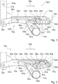
- Figure 1 schematically shows the aircraft seat device with the backrest impact securing device 14a in its locked position.
- the inertia module 16a is in its locked position at a rear end of the respective guide elements 28a, 50a, and the positive locking element 24a of the knee joint 22a engages in the positive locking element 48a of the inertial module 16a, whereby the knee joint 22a is also held in its locked position.
- the articulated arms 40a, 42a are aligned with one another and hold the bolt 36a in its locking position at the rear end of the guide elements 26a.
- the seat component 12a is rigidly coupled to the backrest 10a via the backrest impact securing device 14a. If, in the event of a crash, there is a delay in the opposite direction of flight 66a, to which the backrest impact securing device 14a is aligned in parallel, the housing element 20a coupled to the stand unit is decelerated and the inertia module 16a mounted axially in the housing element 20a is deflected out of its locked position by its inertia and moved toward the front end of the housing member 20a.
- the interlocking element 48a of the inertia module 16a initially releases from the interlocking element 24a of the knee joint 22a, as a result of which the knee joint 22a is decoupled from the inertia module 16a.
- the knee joint 22a is deflected downward via the deflection unit 34a and the joint arms 40a, 42a are thus deflected from one another in alignment.
- the inertia module 16a passes over the actuation elevation 60a with the actuation surface 64a and thus deflects the second articulated arm 42a downward.
- the bolt 36a in the guide elements 26a is released and the bolt 36a can move in the axial direction together with the connecting element 18a in the guide elements 26a (cf. Figure 2 ).
- the backrest 10a is now at least partially decoupled from the seat component 12a.
- the backrest 10a Due to the partial decoupling of the backrest 10a from the seat component 12a, the backrest 10a can rotate about the bearing point 68a, by means of which the backrest 10a is pivotably mounted. Due to inertia in the event of a crash, a large part of the backrest 10a is accelerated in the direction of flight 66a. The majority of the backrest 10a moves in the direction of flight 66a in the event of a crash. Due to the inertia and due to the pivotable mounting of the backrest 10a around the bearing point 68a, a lower region of the backrest 10a moves against the flight direction 66a.
- the seat bottom 58a is also moved against the direction of flight 66a.
- the delay element 30a which counteracts the movement of the housing element 20a, brakes the movement of the backrest 10a and thus also a movement of the seat bottom 58a against the direction of flight 66a.
- a position of the backrest safety device 14a during a crash is shown in FIG Figure 3 shown.
- Figure 4 shows a maximum displacement of the housing element 20a to the bolt 36a and the connecting element 18a.
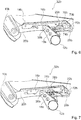
- the Figures 6 and 7 show an aircraft seat device according to the invention in a second embodiment.
- the aircraft seat device is part of a partially illustrated aircraft seat 32b.
- the aircraft seat device comprises a backrest 10b.
- the backrest 10b is provided so that a person sitting on the aircraft seat 32b, of which the aircraft seat device is part, can support his back on the backrest 10b.
- the aircraft seat device further comprises a seat component 12b.
- the aircraft seat device includes a backrest impact safety device 14b.
- the backrest impact securing device 14b is provided to partially decouple the backrest 10b from the seat component 12b in at least one operating state.
- the backrest impact securing device 14b comprises an inertia module 16b and a housing element 20b, in which the inertia module 16b is axially displaceably mounted.
- the inertia module 16b like the inertia module from the first exemplary embodiment, is intended to be deflected from a locking position in the event of a crash.
- the housing element 20b is essentially of the same design as the housing element from the first exemplary embodiment.
- the backrest impact securing device 14b comprises a connecting element 18b.
- the connecting element 18b is provided to be coupled to the seat component 12b.
- the connecting element 18b connects the backrest safety device 14b to the seat component 12b.
- the connecting element 18b is connected to the backrest safety device 14b.
- the backrest impact securing device 14b has two guide elements 26b.
- the guide elements 26b are designed as guide grooves.
- the backrest impact securing device 14b comprises a bolt 36b which connects the connecting element 18b to the backrest impact securing device 14b via the guide elements 26b.
- the bolt 36b is supported in the guide elements 26b.
- the backrest impact securing device 14b comprises a locking element 70b.
- the locking element 70b is pivotally mounted in a front region of the housing element 20b via a pin element 72b.
- the locking element 70b has a locking position ( Figure 6 ). In the locking position, the locking element 70b locks the bolt 36b in its locking position with a form-locking element 74b.
- the form-locking element 74b is arranged at a front free end of the locking element 70b.
- the locking element 70b has a guide element 76b.
- the guide element 76b is designed as a groove.
- the Guide element 76b of the locking element 70b is coupled to a pin element of the inertia module 16b, not shown in any more detail.
- the guide element 76b of the locking element 70b is oriented obliquely to guide elements 28b, via which the inertia module 16b is mounted in the housing element 20b.
- the pin element of the inertia module 16b in the guide element 76b of the locking element 70b shifts.
- the blocking element 70b is pivoted with the front free end to the housing element 20b.
- the locking element 70b releases the bolt 36b and the latter can be displaced in the guide elements 26b in which the bolt 36b is slidably mounted.
- FIG 8 shows part of an aircraft seat device according to the invention in a third embodiment.
- the aircraft seat device includes a backrest impact safety device 14c.
- the backrest impact securing device 14c is provided to partially decouple a backrest from a seat component in at least one operating state.
- the shows Figure 8 only a housing element 20c of the backrest impact securing device 14c in a sectional view.
- the backrest safety device 14c comprises a plurality of delay elements 30c. In contrast to the other exemplary embodiments, only the delay elements 30c differ from the delay elements of the other exemplary embodiments.
- the delay elements 30c are each designed as a web that spans a guide element 26c designed as a groove.
- the delay elements 30c designed as a web extend transversely to a main direction of extension of the guide element 26c and connect one side of the guide element 26c designed as a groove to an opposite side of the guide element 26c.
- the delay elements 30c are each arranged at a distance from one another.
- a bolt, not shown, which is axially displaceably mounted in the guide element 26c and which couples the housing element 20c to the seat component, must destroy the delay elements 30c in order to move in the guide element 26c, as a result of which energy is dissipated and and the bolt and thus the backrest coupled to it Delay elements 30c are delayed. It is conceivable that the plurality of delay elements 30c have different resistances against destruction and thus a defined power reduction, i.e.
- the backrest impact securing device 14c has two holding elements 78c, which are arranged at a first end of the guide element 26c designed as a groove.
- the holding elements 78c are designed as hooks which protrude inwards into the guide element 26c designed as a groove.
- the bolt For displacement in the guide element 26c designed as a groove, the bolt must first destroy the holding elements 78c.
- Figure 9 shows a part of an aircraft seat device according to the invention in a fourth embodiment.
- the aircraft seat device includes a backrest impact safety device 14d.
- the backrest impact securing device 14d is provided to partially decouple a backrest from a seat component in at least one operating state.
- the backrest safety device 14d includes a delay element 30d. In contrast to the other exemplary embodiments, only the delay element 30d differs from the delay elements of the other exemplary embodiments.
- the delay element 30d is formed in one piece with a guide element 26d designed as a groove, in which a bolt for connecting a seat component designed as a transverse stiffening unit is axially displaceably mounted.
- the guide element 26d which forms the delay element 30c, is designed to taper.
- the guide element 26d has a taper in a direction in which the bolt moves in the event of a crash, the guide element 26d in this case having a width which is smaller than a width of the bolt.
- the bolt For the axial displacement in the guide element 26d, the bolt must widen the guide element 26d, which forms the deceleration element 30d in one piece. Due to the plastic deformation of the guide element 26d, which forms the delay element 30d, energy is dissipated and the bolt is decelerated.
- FIG 10 shows a part of an aircraft seat device according to the invention in a fifth embodiment.
- the aircraft seat device includes a backrest impact safety device 14e.
- the backrest impact securing device 14e is provided to secure a backrest in at least one operating state Partially decouple the seat component.
- the shows Figure 10 only a housing element 20e of the backrest impact securing device 14e in a sectional view.
- the backrest safety device 14e includes a plurality of delay elements 30e. Only the delay elements 30e differ from the delay elements of the other exemplary embodiments.
- the delay elements 30e are designed as tapering of a guide element 26e designed as a groove. In the area of the delay elements 30e, side edges of the guide element 26e designed as a groove each extend inwards toward one another.
- the guide element 26e which is designed as a groove, is narrowed in the region of the delay elements 30e.
- a bolt which is movably mounted in the guide element 26e has to bend up the delay elements 30e, which are designed as tapered portions, as a result of which kinetic energy can be reduced to deformation energy.
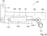
- the Figures 11 to 13 show an aircraft seat device according to the invention in a sixth embodiment.
- the aircraft seat device is part of a partially illustrated aircraft seat 32f.
- the aircraft seat 32f is part of an aircraft, not shown.
- the aircraft seat 32f is mounted in an assembled state in an aircraft cabin of the aircraft.
- the aircraft seat 32f has a stand unit.
- the aircraft seat 32f is mounted on a cabin floor of the aircraft cabin by means of the stand unit.
- the cabin floor forms an elevation level for the aircraft seat 32f.
- the aircraft seat 32f is designed as part of a row of seats which comprises more than one aircraft seat 32f, preferably at least three aircraft seats 32f.
- the aircraft seat 32f forms a seat direction.
- the seat direction is defined as the direction in which a passenger sits on the aircraft seat 32f.
- the seat direction is formed parallel to a flight direction 66f.
- the flight direction 66f is formed by a main extension of the aircraft cabin.
- the stand unit is designed as a common stand unit of the aircraft seats 32f of the row of aircraft seats.
- the aircraft seat device comprises a backrest 10f.
- the backrest 10f is provided so that a person sitting on the aircraft seat 32f, of which the aircraft seat device is a part, can support his back on the backrest 10f.
- the backrest 10f is arranged pivotably to the stand unit.
- the backrest 10f is pivotally articulated on a seat divider, not shown, via a bearing 68f.
- the aircraft seat device further includes a seat member 12f.
- the seat component 12f is designed as a transverse stiffening unit which is provided to stiffen the backrest 10f in the transverse stiffening unit direction.
- the seat component 12f designed as a transverse stiffening unit is provided to connect one side of the aircraft seat 32f, the part of which is the aircraft seat device, to the other side of the aircraft seat 32f.
- the seat component 12f which is designed as a transverse stiffening unit, extends between the seat dividers of the aircraft seat 32f, which are not shown in detail.
- the seat component 12f, which is designed as a transverse stiffening unit is rotatably mounted in the seat dividers (not shown).
- the seat component 12f designed as a transverse stiffening unit is intended to be rotated when the backrest 10f moves.
- the seat component 12f designed as a cross-stiffening unit is designed as a torsion element.
- the seat component 12f designed as a transverse stiffening unit is designed as a torsion tube.
- the aircraft seat device has a seat bottom 58f.
- the seat component 12f is designed as a seat bottom or a component of the seat structure.
- the seat bottom 58f forms a seat surface.
- the seat bottom 58f is coupled to the backrest 10f.
- the backrest 10f and the seat bottom 58f are connected to one another in an articulated manner.
- the backrest 10f and the seat bottom 58f are pivotally coupled to one another via a kinematics of the aircraft seat device, which are not shown in detail.
- the backrest 10f and the seat base 58f can be moved relative to one another in different positions and can be fixed in these different positions.
- the backrest 10f and the seat bottom 58f are preferably displaceable relative to one another in a stepless manner.
- the backrest 10f is rigidly connected to the seat bottom 58f or a seat structure in a normal operating state and the aircraft seat 32f only has one seat position.
- the aircraft seat device includes a backrest impact safety device 14f.
- the backrest impact securing device 14f is provided, at least in a normal operating state, for rigidly connecting the backrest 10f and the seat component 12f in a locked position.
- the normal operating state which reflects normal and correct use of the aircraft seat 32f
- forces can be transmitted from the backrest 10f into the seat component 12f via the backrest impact securing device 14f.
- the backrest impact safety device 14f, the backrest 10f and the seat component 12f rigidly connects in the locked position, forces can be transmitted to the front, ie in the direction of flight 66 and counter to the direction of flight 66.
- the backrest impact securing device 14f is provided to partially decouple the backrest 10f from the seat component 12f in at least one operating state. Due to the partial decoupling of the backrest 10f from the seat component 12f, the backrest 10f and the seat component 12f can make a relative movement to one another in the event of a crash, in order to reduce the risk of injury to a passenger sitting on the aircraft seat 32f. In particular in the event of a crash with a deceleration counter to the direction of flight 66f, the backrest impact safety device 14f decouples the backrest 10f from the seat component 12f.
- the backrest impact securing device 14f at least partially reduces the impact forces acting on the backrest 10f, which also reduces the force on a passenger who exerts the force on the backrest 10f.
- the backrest 10f and the seat component 12f embodied as a transverse stiffening unit are coupled to one another by means of the backrest impact securing device 14f.
- the backrest safety device 14f has a locked position and an unlocked position. In the locked position, the backrest impact safety device 14f is locked and the backrest 10f is firmly coupled to the seat component 12f. In the locked position of the backrest safety device 14f, the backrest 10f cannot move to the seat component 12f via the backrest safety device 14f.
- the backrest 10f In the unlocked position, the backrest 10f is decoupled from the seat component 12f and can be moved to the seat component 12f. In the unlocked position of the backrest safety device 14f, the backrest 10f can be pivoted to the seat component 12f by an advantageous angle.
- the backrest impact securing device 14f decouples the backrest 10f from the seat component 12f before the impact forces act on the backrest 10f.
- the backrest 10f is decoupled from the seat component 12f in the event of a crash before a passenger strikes the backrest 10f and transmits the impact forces to the backrest 10f.
- the backrest 10f is partially decoupled when the passenger hits the backrest 10f, that is to say when the impact forces from the seat component 12f act upon it, and can thus be moved to the seat component 12f before or during the impact of the passenger on the backrest 10f thus absorbing and / or advantageously deflecting part of the impact forces, so that an impact on the backrest 10f is less hard for the passenger.
- the backrest 10f is intended to be locked again in a locking position after the partial decoupling.
- the backrest 10f can be locked again in the locking position after the partial decoupling and the movement to the seat component 12f that has been carried out in the process.
- the locking position can be the same in which the backrest 10f is locked in the normal operating state, but it is also conceivable that the locking position in which the backrest 10f is locked again after the partial decoupling is different from the locking position in the normal operating state.
- the backrest 10f can be secured in the locked position again by a passenger after an adjustment from the locking position in the event of a crash, in order to enable a safe escape route in which the backrest 10f is not in the way.
- the backrest impact securing device 14f is intended to be brought into a locking position again after the partial decoupling and thereby to lock the backrest 10f back into the locking position after the partial decoupling.
- the aircraft seat device it would also be conceivable for the aircraft seat device to have a device which is separate from the backrest impact securing device 14f and is intended to bring the backrest 10f back into a locked position after the partial decoupling.
- the separately designed device is constructed in a similar way and functions as the backrest impact securing device 14f described below. In principle, it is also conceivable that the separately designed device only has the same effect as the backrest impact securing device 14f described below, but that its structure differs.
- the backrest impact safety device 14f comprises a housing 80f.
- the housing 80f is intended to house the backrest impact safety device 14f.
- the housing 80f is designed as a closed housing.
- the housing 80f is designed as a cylinder.
- the housing 80f formed as a cylinder has a central axis that corresponds to a main direction of extent of the housing 80f.
- the housing 80f encloses an interior.
- the housing 80f encloses the entire interior in an assembled state. This can advantageously prevent the ingress of liquids or dirt into the interior of the housing 80f and thus improve the reliability of the backrest impact safety device 14f. In principle, however, it is also conceivable for the housing 80f to be at least partially open.
- the housing 80f comprises a connection element 82f.
- the connecting element 82f is designed as a form-locking element and is provided for rigid connection to an equivalent connecting element.
- the connecting element 82f is arranged at a first axial end of the housing 80f and thus forms a first axial end of the backrest impact securing device 14f.
- the housing 80f can be rigidly connected to the backrest 10f via the connecting element 82f.
- the backrest impact safety device 14f is connected to the backrest 10f via the connecting element 82f of the housing 80f.
- the backrest impact securing device 14f comprises an element 84f which is mounted in an axially displaceable manner in the housing 80f.
- the element 84f is designed as a piston element.
- the element 84f designed as a piston element extends in the assembled state in the interior of the housing 80f.
- a first axial end of element 84f faces the first axial end of housing 80f.
- the element 84f extends from a second axial end of the housing 80f to beyond a center between the first end and the second end of the housing 80f.
- the element 84f is at least essentially rotationally symmetrical and has a central axis. At least one area of the element 84f arranged in the housing 80f is designed to be rotationally symmetrical.
- the central axis of the element 84f is aligned coaxially to the central axis of the housing 80f in the assembled state.
- the element 84f protrudes from the housing 80f.
- the housing 80f has a through opening 98f at the second axial end.
- the element 84f comprises a connection element 86f.
- the connecting element 86f is designed as a form-locking element and is provided for rigid connection to an equivalent connecting element.
- the element 84f can be rigidly connected to the seat component 12f via the connecting element 86f.
- the backrest impact safety device 14f is above the connecting element 86f of the element 84f connected to the seat component 12f.
- the connecting element 86f is arranged at a second axial end of the element 84f.
- the connecting element 86f thereby forms a second axial end of the backrest safety device 14f.
- the backrest impact securing device 14f has a stop 156f.
- the stop 156f is intended to limit the element 84f to a maximum position in the housing 80f.
- the stop 156f is formed by elevations which rise inwards in the interior of the housing 80f.
- the stop 156f limits movement of the element 84f in the housing 80f towards the first axial end of the housing 80f.
- the element 84f strikes the stop 156f.
- the element 84f has an elevation 158f which in the locked position strikes the stop 156f.
- the backrest safety device 14f has a locked position and an unlocked position. In principle, it is also conceivable that the backrest safety device 14f has at least two locking positions that differ from one another.
- the element 84f In the locked position of the backrest safety device 14f, the element 84f, which is axially displaceably mounted in the housing 80f, is rigidly connected to the housing 80f. The element 84f cannot be moved in the housing 80f in the locked position of the backrest impact securing device 14f.
- the unlocked position of the backrest safety device 14f the element 84f, which is axially displaceably mounted in the housing 80f, can move by a defined travel path.
- the element 84f can be moved out of the locked position of the backrest safety device 14f in a release direction which is directed away from the connecting element 82f of the housing 80f. This allows the backrest safety device 14f to be extended by moving the element 84f out of the locked position. By moving the element 84f out of the locking position in the release direction, a distance between the connecting element 82f of the housing 80f and the connecting element 86f of the element 84f is increased.
- the backrest impact protection device 14f has at least one locking module 88f, which locks the backrest impact protection device 14f in a locking position.
- the locking module decouples in the unlocked position 88f at least partially the backrest safety device 14f.
- the backrest safety device 14f can be transferred from the unlocked position into the locked position by means of the locking module 88f.
- the housing 80f and the axially displaceably mounted element 84f are coupled to one another via the locking module 88f in the locked position of the backrest impact securing device 14f.
- the locking module 88f has two locking elements 90f, 92f that can be deflected against an elastic force.
- the locking elements 90f, 92f are designed as pivotable lever elements.
- the locking elements 90f, 92f are arranged in the interior of the housing 80f.
- the locking elements 90f, 92f are designed as elongated lever elements which have a main direction of extension, which in the assembled state is aligned parallel to a main direction of extension of the housing 80f.
- the locking elements 90f, 92f each have a circular ring segment as a cross section orthogonal to their main direction of extension.
- the locking elements 90f, 92f are arranged mirror-inverted to one another in relation to a central axis of the cylindrical housing 80f.
- the locking elements 90f, 92f each have a bearing point 94f, 96f, via which the locking elements 90f, 92f are arranged pivotably in the housing 80f.
- the bearing points 94f, 96f each form a first, housing-side bearing element (not described in more detail), which is formed by the housing 80, and a second bearing element formed by the respective locking element 90f, 92f.
- the bearing elements are each designed as plain bearings. In principle, it would also be conceivable that roller bearings are used for mounting the locking elements 90f, 92f.
- the bearing points 94f, 96f are each arranged on a side facing the second axial end of the housing 80f. Via the bearing points 94f, 96f, a front axial end of the locking elements 90f, 92f, which in the assembled state is assigned to the second axial end of the housing 80f, can be pivoted outward into an open position.
- the two locking elements 90f, 92f are coupled to one another via a spring element 100f.
- the spring element 100f exerts a spring force on the locking elements 90f, 92f, which pushes the locking elements 90f, 92f away from one another in the rear axial end.
- the spring element 100f is designed as a spiral spring. In principle, it would also be conceivable for the spring element to be designed as another spring element that appears to be useful to the person skilled in the art.
- the spring element 100f presses the locking elements 90f, 92f into an idle state via its spring force.
- the locking elements 90f, 92f of the locking module 88f each have a form-locking element 102f, 104f at their front end.
- the interlocking elements 102f, 104f are each designed as a tooth profile, which is arranged on an inward-facing inside of the locking elements 90f, 92f. In principle, it is also conceivable that the positive locking elements 102f, 104f have a different shape.
- the interlocking elements 102f, 104f of the locking elements 90f, 92f form a part of the locking module 88f fixed to the housing.
- the form-locking elements 102f, 104f are fixedly coupled to the housing 80f via the pivotable mounting of the locking elements 90f, 92f.
- the element 84f has a correspondingly designed form-fitting element 106f.
- the form-fitting element 106f is designed as a toothing running around the element 84f, which is complementary to the tooth profiles of the form-fitting elements 102f, 104f of the locking elements 90f, 92f.
- the positive locking elements 102f, 104f engage in the positive locking element 106f, which is formed by the element 84f.
- the element 84f and the housing 80f are rigidly connected to one another via the locking elements 90f, 92.
- the spring element 100f presses the form-locking elements 102f, 104f into the form-locking element 106f via the deflection via the bearing points 94f, 96f.
- the locking module 88f is constructed in a different way and, for example, deflects the locking elements 90f, 92 in an unlocking position by an electromagnetic force and blocks it in a locking position by an electromagnetic force.
- the backrest safety device 14f comprises an inertia module 16f.
- the inertia module 16f is provided to at least partially unlock the backrest safety device 14f in the event of a crash. In the normal operating state of the backrest safety device 14f, the inertia module 16f is arranged in a locked position.
- the locked position of the inertia module 16f is formed by an area in which the inertia module 16 can be arranged without this partially unlocking the backrest impact securing device 14f.
- the inertia module 16f is formed by a mass element 108f, which is arranged axially displaceably in the interior of the housing 80f.
- the mass element 108f is arranged at a first axial end of the housing 80f.
- the mass element 108f has a cylindrical shape.
- the mass element 108f is mounted in the interior of the housing 80f via a slide bearing.
- the mass element 108f has a flat wall at its first end, which in the assembled state faces the first axial end of the housing 80f.
- the mass element 108f has an actuating contour 110f.
- the actuating contour 110f is concave.
- the actuating contour 110f has a conical shape.
- the actuating contour 110f extends inward from the first end of the mass element 108f from a radial outer region in the direction of the second end of the mass element 108f.
- the actuating contour 110f is provided to deflect the locking elements 90f, 92f from their rest position.
- the mass element 108f for deflecting the locking elements 90f, 92f is provided to press the locking elements 90f, 92f towards each other at their rear ends.
- the actuating contour 110f forms a different shape, such as, for example, a spherical shape, an elliptical shape or a mixed shape.
- a triggering delay can be set by designing the actuating contour 110f and by the contour of the locking elements 90f, 92f and the weight of the mass element 108f.
- a release speed can also be set.
- the inertia module 16f is provided for unlocking the backrest safety device 14f to deflect the locking elements 90f, 92f at least temporarily.
- the inertia module 16f for unlocking the backrest safety device 14f is provided to be deflected from its locked position.
- the inertia module 16f is intended to be deflected from a locking position before the impact forces act. If the inertia module 16f is deflected from its locking position, the backrest impact securing device 14f moves from the locking position into the unlocking position.
- the inertia module 16f forms the mass element 108f.
- the mass element 108f is provided to give the inertia module 16f a mass, which, due to its inertia in a crash, deflects the inertia module 16f in the backrest safety device 14f from its locking position and at least partially unlocks the backrest safety device 14f by deflecting the locking elements 90f, 92f.
- the backrest impact securing device 14f has at least one spring element 112f, which is provided to hold the inertial module 16f in its locked position.
- the spring element 112f is arranged in the interior of the housing 80f.
- the spring element 112f is functionally arranged between the housing 80f and the inertia module 16f.
- the spring element 112f is supported on the housing 80f and exerts a spring force on the inertia module 16f which is axially displaceably mounted in the housing 80f.
- the spring element 112f abuts the mass element 108f at a first end. With a second end, the spring element 112f is supported on an inner side of the housing 80f via a connection region (not shown in more detail).
- the spring element 112f is arranged between the second end of the housing 80f and the mass element 108f of the inertia module 16f.
- the spring element 112f is designed as a compression spring. As a result, the mass element 108f of the inertia module 16f in the housing 80f is pressed toward its first position in the locked position. In the event of a crash, the mass element 108f must move in the triggering direction against the spring force of the spring element 112f in order to unlock the backrest impact safety device 14f.
- the spring element 112f is designed as a spiral spring. In principle, it is also conceivable that the spring element 112f is designed as another spring element that appears to be useful to the person skilled in the art, such as a gas pressure spring, a magnetic and / or electrical spring element or a spring element that generates a restoring force by compressing a fluid.
- the backrest safety device 14f comprises a delay element 30f.
- the delay element 30f is for absorbing inertial energy of the backrest 10f after the partial decoupling of the backrest safety device 14f provided.
- the deceleration element 30f absorbs at least some of the inertial forces which act on the backrest 10f.
- the delay element 30f is provided to be plastically deformed.
- the delay element 30f is arranged in the interior of the housing 80f.
- the delay element 30f is functionally arranged between the element 84f and the housing 80f.
- the delay element 30f is provided to brake a relative movement of the element 84f to the housing 80f after the partial decoupling before an end stop.
- the delay element 30f is designed as a plastically deformable sleeve.
- the delay element 30f encloses the piston-like element 84f.
- the element 84f has a driving element 114f.
- the driving element 114f is firmly connected to the element 84f. In principle, it is also conceivable that the driving element 114f is formed in one piece with the element 84f.
- the delay element 30f is arranged between the driver element 114f and the second end of the housing 80f.
- the driving element 114f takes the delay element 30f with it until it abuts against an axial inner wall on the second end of the housing 80f.
- the delay element 30f is clamped between the entraining element 114f and the inner wall at the second end of the housing 80f and plastically deformed. Due to the plastic deformation of the delay element 30f, a kinetic energy of the backrest 10f is converted into forming work and thereby destroyed.
- the one adjustment of the element 84f to the housing 80f and thus an adjustment of the backrest 10f after the partial decoupling is delayed before a maximum adjustment and is not braked abruptly.
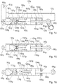
- FIG 11 schematically shows the aircraft seat device with the backrest impact securing device 14f in its locked position.
- the inertia module 16f is in its locked position.
- the housing 80f is rigidly connected to the element 84f by the locking module 88f.
- the connecting element 82f, which is coupled to the backrest 10f, and the connecting element 86f, which is coupled to the seat component 12f coupled is rigidly connected to one another. Forces can be transmitted between the backrest 10f and the seat component 12f via the connection elements 82f, 86f via the backrest impact securing device 14f.
- the housing 80f coupled to the stand unit via the backrest 10f is decelerated and the inertia module 16f mounted axially in the housing 80f is characterized by its inertia deflected its locking position and moved against the spring force of the spring element 112f in the direction of the second end of the housing 80f.
- the locking elements 90f, 92f are pivoted out of their rest position and the positive connection between the locking elements 90f, 92f coupled to the housing 80f and the element 84f via the positive locking elements 102f, 104f, 106f is canceled.
- the backrest safety device 14f is thereby partially unlocked.
- Element 84f can slide in housing 80f relative to housing 80f.
- the backrest 10f is now at least partially decoupled from the seat component 12f.
- the backrest 10f Due to the partial decoupling of the backrest 10f from the seat component 12f, the backrest 10f can rotate about the bearing point 68f, by means of which the backrest 10f is pivotably mounted. Due to inertia in the event of a crash, a large part of the backrest 10f is accelerated in the direction of flight 66f. The majority of the backrest 10f moves in the direction of flight 66f in the event of a crash. Due to the inertia and due to the pivotable mounting of the backrest 10f around the bearing point 68f, a lower region of the backrest 10f moves counter to the direction of flight 66f.
- the delay element 30f is carried along with the element 84f via the driving element 114f and is also moved relative to the housing 80f.
- the delay element 30f is clamped and deformed by the relative movement between the housing 80f and the element 84f between the driving element 114f and the housing 80f.
- the delay element 30f delays the relative movement between the housing 80f and the element 84f and thereby the pivoting movement of the backrest 10f.
- the backrest impact securing device 14f is intended to be brought into a locking position again after the partial decoupling.
- the backrest 10f can be locked again after an adjustment during the crash and an escape route can advantageously be kept free for a passenger.
- the backrest 10f is pivoted with its upper region forward in the direction of flight 66f. If the backrest 10f is pivoted backwards again, the housing 80f is displaced again in the direction of flight 66f and thus moves relative to the element 84f.
- the locking elements 90f, 92f held in their rest position by the spring element 100g are deflected outward again by the oblique toothing of the form-locking element 106f, which is formed by the element 84f.
- the interlocking elements 102f, 104f can be brought back into engagement with the interlocking element 106f of the element 84f.
- the housing 80f can again be rigidly coupled to the element 84f and the backrest impact securing device 14f can thereby be locked again.
- the Figures 14 to 16 show an aircraft seat device according to the invention in a seventh embodiment.
- the aircraft seat device is part of a partially illustrated aircraft seat 32g.
- the aircraft seat 32g is part of an aircraft, not shown.
- the aircraft seat 32g is mounted in an assembled state in an aircraft cabin of the aircraft.
- the aircraft seat device comprises a backrest 10g.
- the backrest 10g is provided so that a person sitting on the aircraft seat 32g, of which the aircraft seat device is part, can support his back on the backrest 10g.
- the backrest 10g is pivotally connected to a seat divider, not shown, via a bearing 68g.
- the aircraft seat device further comprises a seat component 12g.
- the seat component 12g is as a transverse stiffening unit is formed, which is intended to stiffen the backrest 10g in the transverse stiffening unit transverse direction.
- the seat component 12g designed as a transverse stiffening unit is provided to connect one side of the aircraft seat 32g, the part of which is the aircraft seat device, to the other side of the aircraft seat 32g.
- the aircraft seat device has a seat bottom 58g.
- the seat component 12g is designed as a seat bottom or a component of the seat structure.
- the seat bottom 58g forms a seat surface.
- the seat bottom 58g is coupled to the backrest 10g.
- the aircraft seat device includes a backrest impact safety device 14g.
- the backrest impact securing device 14g is provided, at least in a normal operating state, for rigidly connecting the backrest 10g and the seat component 12g in a locked position.
- a normal operating state which depicts normal and correct use of the aircraft seat 32g
- forces can be transmitted from the backrest 10g into the seat component 12g via the backrest impact securing device 14g.
- the backrest impact securing device 14g is provided to partially decouple the backrest 10g from the seat component 12g in at least one operating state.
- the backrest 10g and the seat component 12g can exert a relative movement in the event of a crash, in order to reduce the risk of injury to a passenger sitting on the aircraft seat 32g.
- the backrest impact securing device 14g decouples the backrest 10g from the seat component 12g before the impact forces act on the backrest 10g.
- the backrest 10g is intended to be locked again in a locking position after the partial decoupling.
- the backrest 10g can be locked again in the locking position after the partial decoupling and the movement to the seat component 12g which has been carried out in the process.
- the locking position can be the same in which the backrest 10g is locked in the normal operating state, but it is also conceivable that the locking position in which the backrest 10g is locked again after the partial decoupling is different from the locking position in the normal operating state.
- the backrest impact securing device 14g comprises a housing 80g.
- the housing 80g is intended to house the backrest impact safety device 14g.
- the housing 80g comprises a connection element 82g.
- the connecting element 82g is designed as a form-locking element and is provided for rigid connection to an equivalent connecting element.
- the connecting element 82g is arranged at a first axial end of the housing 80g and thus forms a first axial end of the backrest impact securing device 14g.
- the housing 80g can be rigidly connected to the backrest 10g via the connecting element 82g.
- the backrest impact securing device 14g comprises an element 84g which is mounted in an axially displaceable manner in the housing 80g.
- the element 84g is designed as a piston element.
- the element 84g designed as a piston element extends in the assembled state in the interior of the housing 80g. In the assembled state, a first axial end of the element 84g faces the first axial end of the housing 80g. At a second axial end of the housing 80g, which is opposite the first axial end of the housing 80g, the element 84g protrudes from the housing 80g.
- the element 84g comprises a connecting element 86g.
- the connecting element 86g is designed as a form-locking element and is provided for rigid connection to an equivalent connecting element.
- the element 84g can be rigidly connected to the seat component 12g via the connecting element 86g.
- the backrest impact securing device 14g has a stop 156g.
- the stop 156g is intended to limit the element 84g to a maximum position in the housing 80g.
- the stop 156g is formed by elevations which rise inwards in the interior of the housing 80g.
- the stop 156g is in particular formed by a bushing which is introduced into the interior of the housing 80g.
- the stop 156g limits movement of the element 84g in the housing 80g towards the first axial end of the housing 80g. In the locked position, the element 84g strikes the stop 156g.
- the backrest safety device 14g has at least one locking module 88g, which locks the backrest safety device 14g in a locked position.
- the locking module 88g of the backrest safety device 14g differs from the locking module of the corresponding backrest safety device from the sixth embodiment of FIG Figures 11 to 13 .
- the locking module 88g has two locking elements 90g, 92g, which are designed as piston-fixed, elastically deformable levers.
- the Locking elements 90g, 92g are formed in one piece with the element 84g.
- the locking elements 90g, 92g are formed from an elastically deformable material.
- the locking elements 90g, 92g extend from the element 84g in the direction of a first end of the housing 80g.
- the locking elements 90g, 92g are arranged at a distance from one another.
- the locking elements 90g, 92g are each connected to the element 84g with a first end which faces the element 84g. In the direction of their second ends, which face away from the element 84g, the locking elements 90g, 92g have an increasing distance.
- the two locking elements 90g, 92g together form a form-locking element 116g in the region of their second ends.
- the form-locking element 116g is formed by two notches 120g, 122g facing one another in the inner sides of the locking elements 90g, 92g.
- the notches 120g, 122g in the locking elements 90g, 92g face each other.
- the notches 120g, 122g are made at an equal distance from the element 84 in the respective locking element 90g, 92g.
- the two notches 120g, 122g form a triangular shape in an undeflected state of the locking elements 90g, 92g.
- a tip of the triangular form-locking element 116g is directed in the direction of the element 84g.
- the locking module 88g has a form-locking element 124g fixed to the housing.
- the form-locking element 124g is rigidly connected to the housing 80g.
- the form-locking element 124g extends across the interior of the housing 80g.
- the interlocking element 124g is designed to be equivalent to the interlocking element 116g formed by the locking elements 90g, 92g.
- the form-locking element 124g has a triangular cross section. In principle, it is also conceivable that the form-locking element 124g has a different cross-section, such as a semicircular shape, a circular shape or an elliptical shape.
- the corresponding form-locking element 116g formed by the locking elements 90g, 92g would accordingly be equivalent.
- the form-locking element 124g is formed by a triangular-shaped bolt which is guided through the interior of the housing 80g. The bolt that forms the form-locking element 124g is firmly connected to the housing 80g.
- the locking elements 90g, 92g embrace the form-locking element 124g.
- the positive locking element 124g is arranged in the locking position in the notches 120g, 122g of the locking elements 90g, 92g forming the positive locking element 116g.
- the form-locking element 124g and the form-locking element 116g are form-fitting connected with each other.
- the backrest safety device 14g is locked and a force can be transmitted via the backrest safety device 14g between the backrest 10g and the seat component 12g.
- the backrest safety device 14g comprises an inertia module 16g.
- the inertia module 16g is provided to at least partially unlock the backrest safety device 14g in the event of a crash.
- the inertia module 16g is configured essentially the same as the inertia module from the sixth exemplary embodiment in FIG Figures 11 to 13 .
- the inertia module 16g is formed by a mass element 108g, which is arranged axially displaceably in the interior of the housing 80g.
- the mass element 108g is arranged at a first axial end of the housing 80g.
- the mass element 108g has a differently shaped actuation contour 110g.
- the actuating contour 110g is convex.
- the actuating contour 110g has a convex conical shape.
- the actuating contour 110g extends inward from a first end of the mass element 108g, which faces the locking elements 90g, 92g, from a radial outer region in the direction of the locking elements 90g, 92g.
- the inertia module 16g is provided for releasing the positive connection between the form-locking elements 116g, 124g.
- the convex wedge-shaped actuating contour 110g is provided to push the locking elements 90g, 92g apart, in order to release the form-locking element 124 fixed to the housing from the wrapping of the form-locking element 116g formed by the locking elements 90g, 92g.
- the actuating contour 110g is provided to deflect the locking elements 90g, 92g from their rest position.
- the mass element 108g is provided for deflecting the locking elements 90g, 92g to push the locking elements 90g, 92g apart at their second end.
- the backrest impact securing device 14g has at least one spring element 112g, which is provided to hold the inertial module 16g in its locked position.
- the backrest safety device 14g comprises a delay element 30g.
- the delay element 30g is for receiving Inertia energy of the backrest 10g is provided after the partial decoupling of the backrest safety device 14g.
- the delay element 30g is configured in the same way as the corresponding delay element from the backrest safety device from the sixth exemplary embodiment of FIG Figures 11 to 13 .
- the delay element 30g differs from the corresponding delay element from the backrest safety device from the sixth exemplary embodiment in FIG Figures 11 to 13 .
- the delay element 30g is designed as a damping element.
- the delay element 30g designed as a damping element, is intended to absorb kinetic energy without plastic deformation.
- the delay element 30g is designed as a gas pressure spring.
- the delay element 30g is provided to absorb energy by flowing a fluid.
- the delay element 30g has an aperture 150g which separates two chambers 152g, 154g from one another.
- the aperture 150g is firmly connected to the element 84g.
- the orifice 150g separates the two chambers 152g, 154g in the interior of the housing from the element 84g radially on the inside to the housing 80g radially on the outside.
- the orifice 150g has a plurality of through holes, not shown, through which the two chambers 152g, 154g separated from the orifice 150g are connected to one another in terms of fluid technology.
- a fluid can pass from one chamber 152g into the other chamber 154g through the through holes.
- the fluid can be a gas or a liquid.
- the through holes are closed in a normal state by membranes, which are destroyed in a crash by the movement of the element 84g and the fluid and thus expose the through holes.
- the chamber 152g is reduced by the orifice 150g and the fluid arranged in the chamber flows through the through openings of the orifice 150g into the chamber 154g. As a result, energy is reduced and the backrest 10g is delayed.
- An operation of the delay element 30g in the event of a crash corresponds to that of the previous exemplary embodiment.
- the backrest impact securing device 14g can be locked into the locking position again after being partially uncoupled.
- the element 84g is moved by moving the backrest 10g moved relative to the housing 80g, so that the form-fitting element 116g of the locking elements 90g, 92g and the form-fitting element 124g fixed to the housing come into engagement again.
- the locking elements 90g, 92g are again pressed over the form-locking element 124g and snap back into the form-locking element 124g with their notches 120g, 122g by a restoring force generated by the deflection of the locking elements 90g, 92g.
- the backrest impact securing device 14g is again in the locked position and the backrest 10g is locked again.
- FIGS 17 to 20 show an aircraft seat device according to the invention in an eighth embodiment.
- the aircraft seat device is part of an aircraft seat, not shown.
- the aircraft seat device comprises a backrest and a seat component in accordance with the preceding exemplary embodiments, which are not described in more detail here.
- the seat component is designed as a cross stiffening unit which is provided to stiffen the backrest in the cross stiffening unit cross direction.
- the aircraft seat device includes a backrest impact safety device 14h.
- the backrest impact securing device 14h is provided, at least in a normal operating state, for rigidly connecting the backrest and the seat component in a locking position.
- the backrest impact securing device 14h is connected to the backrest and the seat component in accordance with the backrest impact securing devices of the preceding exemplary embodiments.
- the backrest impact securing device 14h is provided to partially decouple the backrest from the seat component in at least one operating state.
- the backrest impact securing device 14h decouples the backrest from the seat component before the impact forces act on the backrest.
- the backrest is intended to be locked again in a locking position after the partial decoupling.
- the backrest safety device 14h includes a housing 80h.
- the housing 80h is provided for the backrest impact safety device 14h to surround.
- the housing 80h comprises a connection element, not shown, via which the housing 80h is coupled to the seat component in the assembled state.
- the backrest impact securing device 14h comprises an element 84h which is mounted in an axially displaceable manner in the housing 80h.
- the element 84h is designed as a piston element.
- the element 84h designed as a piston element extends in the assembled state into the interior of the housing 80h.
- the element 84h comprises a connection element, not shown, via which the element 84h is coupled to the backrest in the assembled state.
- the backrest impact securing device 14h has a locking module 88h, which locks the backrest impact securing device 14h in a locking position.
- the locking module 88h of the backrest safety device 14h differs from the locking module of the corresponding backrest safety device from the previous exemplary embodiments.
- the locking module 88h comprises a coupling element 118h.
- the coupling element 118h is designed as a ball.
- the housing 80h and the element 84h are connected to one another in a locked position via the coupling element.
- the element 84h has a recess 126h in which the coupling element 118h designed as a ball is arranged in the locked position.
- the recess 126h is not drawn to scale in the figures for the sake of clarity.
- the recess 126h is not as deep as shown in the figures in order to prevent the coupling element 118h from tilting.
- the housing 80h forms a shoulder 128h. In the locked position, the coupling element 118h rests positively on the recess 126h and the shoulder 128h. As a result, the housing 80h and the element 84h are connected to one another in the locked position via the coupling element 118h.
- the backrest safety device 14h comprises an inertia module 16h. To secure the coupling element 118h in the locked position, the backrest impact securing device 14h has an inertia module 16h. The inertia module 16h is further provided to at least partially unlock the backrest safety device 14h in the event of a crash.
- the inertia module 16h is formed by a mass element 108h, which is arranged axially displaceably in the interior of the housing 80h. In the locked position, the inertia module 16h is arranged above the coupling element 118h and thus holds the coupling element 118h in the recess 126h of the element 84h. The positive connection between the housing 80h and the element 84h is secured via the inertia module 16h. If the inertia module 16h is deflected against a direction of flight in the event of a crash, the inertia module 16h releases the coupling element 118h and the positive connection between the housing 80h and the element 84h via the coupling element 118h is released.
- the backrest impact safety device 14h is thereby at least partially unlocked and the element 84h can be axially displaced in the housing 80h.
- the backrest impact securing device 14h it is also conceivable for the backrest impact securing device 14h to have further coupling elements 118h and depressions 126h, via which the housing 80h and the element 84h are connected to one another in a form-fitting manner.
- the backrest impact securing device 14h has a spring element 112h, which is provided to hold the inertia module 16h in its locked position.
- the spring element 112h is designed in accordance with the previous exemplary embodiments.
- the spring element 112h is designed as a spiral spring.
- the spring element 112h is arranged between the inertia module 16h and a support wall 130h of the element 84h. In the locked position, the element 84h rests with the support wall 130h on an inner wall of the housing 80h.
- the housing 80h has an opening 132h on its circumference. In principle, it is also conceivable for the housing 80h to have further of these openings 132h on its periphery, for which the following description can also be used.
- the opening 132h is arranged at a rear end of the housing 80h.
- the support wall 130h extends into the opening 132h of the housing 80h.
- the backrest impact securing device 14h has a leaf spring element 134h.
- the leaf spring element 134h is firmly connected to an outside of the housing 80h and projects into the opening 132h. With a loose end, the leaf spring element 134h lies in the locking position on the support wall 130h of the element 84h (see Figure 17 ).
- the support wall 130h has a predetermined breaking point 136h at a height of a lower edge of the opening 132h.
- the area above the predetermined breaking point 136h is provided for breaking off at an edge 138h of the opening 132h during a crash, when the element 84h is axially displaced within the housing 80h (see Figure 19 ). If the area above the predetermined breaking point 136h is broken off, the support wall 130h can move within the housing 80h.
- the predetermined breaking point 136c it would also be conceivable for the support wall 130h to have a joint which extends the area designed pivotable above the joint. It would be conceivable for the support wall to have a film hinge instead of the predetermined breaking point, through which the upper region can be folded down if it abuts the edge 138h of the opening 132.
- the backrest impact securing device 14h has a stop 156h.
- the stop 156h is provided to limit the element 84h to a maximum position in the housing 80h.
- the stop 156h is formed by the support wall 130h, which is supported on the housing 80h.
- the stop 156h limits movement of the element 84h in the housing 80h towards the rear end of the housing 80h. In the locked position, the stop 156h strikes the rear end of the housing 80h.
- the inertia module 16h is first deflected against the spring force of the spring element 112h. Due to the deflection of the inertia module 16h, the coupling element 118h is released and the positive connection between the housing 80h and the element 84h is released via the coupling element 118h.
- the acceleration required to unlock the backrest impact securing device 14h can be designed in a particularly simple and advantageous manner, since only the mass of the mass element 108h and the spring force of the spring element 112h influence this required acceleration.
- the element 84h is displaced in the crash against the flight direction to the housing 80h by the pivoting of the backrest.
- the backrest safety device 14h comprises a delay element 30h.
- the delay element 30h absorbs at least some of the inertial forces that act on the backrest.
- the delay element 30h is provided to be plastically deformed.
- the delay element 30h is arranged between the inertia module 16h and the support wall 130h.
- the delay element 30h is clamped and deformed between the inertia module 16h, which is supported on the shoulder 128h of the housing 80h and the support wall 130h, whereby it absorbs energy (see Figure 19 ).
- the backrest can again be locked into a locking position via the backrest impact securing device 14h to be brought.
- the element 84h is pushed back into the housing 80h.
- the support wall 130h of the element 84h is clamped between an inner wall of the housing 80h and the leaf spring element 134h and thus locked in the locked position.
- the Figure 21 shows an aircraft seat device according to the invention in a ninth embodiment.
- the aircraft seat device is part of a partially illustrated aircraft seat 32i.
- the aircraft seat 32i is part of an aircraft, not shown.
- the aircraft seat 32i is mounted in an assembled state in an aircraft cabin of the aircraft.
- the aircraft seat device comprises a backrest 10i.
- the backrest 10i is provided so that a person sitting on the aircraft seat 32i, of which the aircraft seat device is part, can support his back on the backrest 10i.
- the backrest 10i is pivotally connected to a seat divider, not shown, via a bearing 68i.
- the aircraft seat device further comprises a seat component 12i.
- the seat component 12i is designed as a cross stiffening unit, which is provided to stiffen the backrest 10i in the cross stiffening unit transverse direction.
- the seat component 12i designed as a transverse stiffening unit is provided to connect one side of the aircraft seat 32i, the part of which is the aircraft seat device, to the other side of the aircraft seat 32i.
- the aircraft seat device has a seat bottom 58i.
- the seat component 12i is designed as a seat bottom or a component of the seat structure.
- the seat bottom 58i forms a seat surface.
- the seat bottom 58i is coupled to the backrest 10i.
- the aircraft seat device includes a backrest impact safety device 14i.
- the backrest impact securing device 14i is provided, at least in a normal operating state, for rigidly connecting the backrest 10i and the seat component 12i in a locked position.
- the normal operating state which depicts normal and correct use of the aircraft seat 32i
- forces can be transmitted from the backrest 10i into the seat component 12i via the backrest impact securing device 14i.
- the backrest impact securing device 14i is provided to partially decouple the backrest 10i from the seat component 12i in at least one operating state.
- the backrest safety device 14i is designed like a backrest safety device described in the previous exemplary embodiments.
- the aircraft seat device comprises an additional force element 140i.
- the additional force element 140i is provided to accelerate the backrest 10i at least temporarily immediately before the partial decoupling.
- the additional force element 140i is designed as a gas pressure spring.
- the additional force element 140i is designed as a mechanical spring element or an electro-magnetic spring element.
- the additional force element 140i is designed as a pyrotechnic element that provides its additional force through a pyrotechnic effect.
- the additional force element 140i is functionally arranged between the backrest 10i and the seat component 12i.
- the additional force element 140i is functionally arranged between a housing 80i of the backrest safety device 14i and an element 84i movably mounted in the housing 80i.
- the additional force element 140i has a first connection point 142i, via which the additional force element 140i is rigidly connected to the housing 80i.
- the connection point 142i is arranged on a housing 144i of the additional force element 140i.
- the additional force element 140i has a second connection point 146i, via which the additional force element 140i is rigidly connected to the element 84i of the backrest safety device 14i.
- the connection point 146i is arranged on an extendable piston 148i of the additional force element 140i.
- the additional force element 140i In the locked position of the backrest safety device 14i, the additional force element 140i is arranged pretensioned between its two connection points 142i, 146i.
- the additional force element 140i provides a spring force that pushes apart the mutually movable parts of the backrest impact securing device 14i, such as in particular the housing 80i and the element 84i.
- the additional force element 140i In the locked state of the backrest impact securing device 14i, the additional force element 140i has no influence on the system. If the backrest impact safety device 14i is unlocked during a crash, the additional force element 140i can provide its spring force and thus push the element 84i and the housing 80i apart.
- the spring force provided by the additional force element 140i acts thereby in the same direction as the deceleration force during the crash.
Landscapes
- Engineering & Computer Science (AREA)
- Aviation & Aerospace Engineering (AREA)
- Transportation (AREA)
- Mechanical Engineering (AREA)
- Seats For Vehicles (AREA)
Description
- Die Erfindung betrifft eine Flugzeugsitzvorrichtung nach dem beigefügten Anspruch 1 1.
- Es sind bereits Flugzeugsitzvorrichtungen mit zumindest einer Rückenlehne, mit zumindest einem mit der Rückenlehne gekoppelten Sitzbauteil und mit einer Rückenlehnenaufschlagssicherungsvorrichtung, die durch eine teilweise Entkopplung der Rückenlehne von dem Sitzbauteil dazu vorgesehen ist, Aufschlagskräfte auf die Rückenlehne in einem Crashfall zumindest teilweise zu reduzieren, vorgeschlagen worden.
EP2610178 A2 offenbart eine Sitzvorrichtung, insbesondere eine Flugzeugsitzvorrichtung, mit einer Rückenlehnenaufschlagssicherungseinheit, die dazu vorgesehen ist, Aufschlagkräfte auf eine Rückenlehne in einem Crashfall zumindest teilweise zu reduzieren. Die Rückenlehnenaufschlagssicherungseinheit eine Stelleinheit aufweist, die zumindest dazu vorgesehen ist, einen Sicherungsvorgang einzuleiten.EP2706010 A2 offenbart eine Sitzenergieabsorptionsvorrichtung, insbesondere einer Flugzeugsitzenergieabsorptionsvorrichtung, die dazu vorgesehen ist, zumindest in einem Crashfall zumindest eine Hauptbeschleunigungsbewegung zumindest einer Rückenlehneneinheit zumindest teilweise zu absorbieren. Die Sitzenergieabsorptionsvorrichtung zumindest eine Sitzenergieabsorptionseinheit, die dazu vorgesehen ist, in dem Crashfall in zumindest einer von der Hauptbeschleunigungsbewegung der Rückenlehneneinheit abweichenden Richtung bewegt zu werden, aufweist. - Die Aufgabe der Erfindung besteht insbesondere darin, eine gattungsgemäße Vorrichtung mit verbesserten Eigenschaften hinsichtlich einer Sicherheit bereitzustellen. Die Aufgabe wird erfindungsgemäß durch die Merkmale des Patentanspruchs 1 gelöst, während vorteilhafte Ausgestaltungen und Weiterbildungen der Erfindung den Unteransprüchen entnommen werden können.
- Die Erfindung geht aus von einer Flugzeugsitzvorrichtung mit zumindest einer Rückenlehne, mit zumindest einem mit der Rückenlehne gekoppelten Sitzbauteil und mit einer Rückenlehnenaufschlagssicherungsvorrichtung, die durch eine teilweise Entkopplung der Rückenlehne von dem Sitzbauteil dazu vorgesehen ist, Aufschlagskräfte auf die Rückenlehne in einem Crashfall zumindest teilweise zu reduzieren.
- Die Rückenlehnenaufschlagssicherungsvorrichtung ist dazu vorgesehen die Rückenlehne vor einem Einwirken der Aufschlagskräfte von dem Sitzbauteil zu entkoppeln. Unter einer "Rückenlehne" soll dabei insbesondere ein Bauteil eines Flugzeugsitzes verstanden werden, an dem eine auf dem Flugzeugsitz sitzende Person ihren Rücken abstützen kann. Unter einem "Sitzbauteil" soll dabei insbesondere ein Bauteil eines Flugzeugsitzes verstanden werden, wie insbesondere ein Sitzgestell oder ein Teil einer festen Struktur des Flugzeugsitzes, wie ein Querrohr. Grundsätzlich ist es auch denkbar, dass das Sitzbauteil als ein anderes, dem Fachmann als sinnvoll erscheinendes Bauteil, insbesondere als ein tragendes Bauteil eines Flugzeugsitzes ausgebildet ist. Unter "gekoppelt" soll dabei insbesondere miteinander verbunden verstanden werden. Dabei ist es denkbar, dass zwei Elemente, die miteinander gekoppelt sind, direkt oder indirekt über wenigstens ein weiteres Element miteinander verbunden sind. Unter einer "teilweisen Entkopplung" soll dabei insbesondere verstanden werden, dass eine Bewegung der Rückenlehne und eine Bewegung des Sitzbauteils zumindest für eine definierte Zeit und/oder über eine definierte Verfahrstrecke voneinander getrennt werden, sodass sich die Rückenlehne über eine definierte Zeit und/oder über eine definierte Verfahrstrecke zu dem Sitzbauteil bewegen kann. Unter "Aufschlagskräften" sollen dabei Kräfte verstanden werden, die von Objekten, wie insbesondere von einem Körper eines auf dem Flugzeugsitz sitzenden Passagiers, bei Auftreffen auf ein Element, wie insbesondere die Rückenlehne, entstehen. Unter einem "Crashfall" soll dabei insbesondere ein Überlastfall verstanden werden, also ein Betriebszustand, in dem Kräfte auf die Flugzeugsitzvorrichtung und/oder den Flugzeugsitz, dessen Teil die
- Flugzeugsitzaufständervorrichtung ist, wirken, die größer sind als Kräfte, die durch eine normale Belastung bei einem normalen Flugbetrieb entstehen. Unter "vor einem Einwirken der Aufschlagskräfte" soll dabei insbesondere ein Zeitpunkt, bevor der Körper eines Passagiers auf die Rückenlehne der Flugzeugsitzvorrichtung auftrifft, verstanden werden. Unter "vorgesehen" soll insbesondere speziell ausgelegt und/oder ausgestattet verstanden werden. Darunter, dass ein Objekt zu einer bestimmten Funktion vorgesehen ist, soll insbesondere verstanden werden, dass das Objekt diese bestimmte Funktion in zumindest einem Anwendungs- und/oder Betriebszustand erfüllt und/oder ausführt. Dadurch kann vorteilhaft eine Flugzeugsitzvorrichtung bereitgestellt werden, die in einem Crashfall einen in einem Flugzeugsitz sitzenden Passagier besonders vorteilhaft vor Verletzungen schützt. Durch die Reduzierung der Aufschlagskräfte auf die Rückenlehne werden sowohl die auf die Rückenlehne wirkenden Kräfte als auch die auf den Körper des Passagiers wirkenden Kräfte reduziert, was vorteilhaft eine Verletzungsgefahr reduziert.
- Die Rückenlehnenaufschlagssicherungsvorrichtung aufweist wenigstens ein Trägheitsmodul das dazu vorgesehen ist, die Rückenlehnenaufschlagssicherungsvorrichtung zumindest in einem Crashfall zu entkoppeln. Unter einem "Trägheitsmodul" soll dabei insbesondere ein Modul verstanden werden, das aufgrund einer Massenträgheit ausgelöst und aus einer Verriegelposition gelöst wird. Dabei ist das Trägheitsmodul vorzugsweise von einem Element gebildet, das durch seine Trägheit dazu vorgesehen ist, eine Betätigung auszuführen. Dabei wird das Trägheitsmodul durch seine Massenträgheit bei einem Einwirken von Verzögerungskräften, insbesondere in einem Crashfall, aus einer Verriegelposition ausgelenkt. Dabei wird das Trägheitsmodul vorzugsweise axial entlang einer Verschiebeachse aus der Verriegelposition ausgelöst. Grundsätzlich ist es auch denkbar, dass das Trägheitsmodul entlang einer anders ausgebildeten Verschiebelinie verschoben wird, beispielsweise auf einer Kreisbahn, wenn das Trägheitsmodul eine Art Pendel ausbildet. Dabei kann eine Auslösekraft, die nötig ist, um das Trägheitsmodul aus seiner Verriegelposition auszulenken, über die Masse des Trägheitsmoduls eingestellt werden. Dadurch kann die Auslösekraft für unterschiedlich große Sitze oder unterschiedlich große Sitzabstände in einem Flugzeug einfach eingestellt werden. Grundsätzlich ist es auch denkbar, dass das Trägheitsmodul zumindest einen elektronischen Beschleunigungssensor und einen elektrisch und/oder elektronisch ansteuerbaren Verriegelungsmechanismus aufweist, wobei der Verriegelungsmechanismus bei einer definierten, von dem zumindest einen Beschleunigungssensor erfassten Beschleunigung angesteuert und geöffnet wird. Dabei ist es grundsätzlich denkbar, dass der Verriegelungsmechanismus per Pyrotechnik oder über einen elektro-mechanischen Schalter ausgelöst wird.
- Das Trägheitsmodul ist dazu vorgesehen die Rückenlehnenaufschlagssicherungsvorrichtung zumindest in einem Normalbetriebszustand zu verriegeln. Unter einem "Normalbetriebszustand" soll dabei insbesondere ein Betriebszustand während eines normalen Betriebs der Flugzeugsitzvorrichtung verstanden werden, insbesondere während eines in einem Flugzeug eingebauten Zustands und während eines Betriebs des Flugzeugs. Unter "verriegeln" soll dabei insbesondere in einer definierten Position, insbesondere in einer Verriegelposition halten verstanden werden. Dadurch kann die Rückenlehne in dem Normalbetriebszustand vorteilhaft zu dem Sitzbauteil fixiert werden, sodass eine normale Benutzung der Flugzeugsitzvorrichtung erreicht werden kann. Dadurch kann die Rückenlehnenaufschlagssicherungsvorrichtung vorteilhaft einfach mittels des Trägheitsmoduls verriegelt werden.
- Ferner wird vorgeschlagen, dass das Trägheitsmodul im Crashfall zur Entriegelung der Rückenlehnenaufschlagssicherungsvorrichtung dazu vorgesehen ist, aus einer Verriegelposition ausgelenkt zu werden. Unter einer "Verriegelposition" soll dabei insbesondere eine Position bzw. Stellung der Rückenlehnenaufschlagssicherungsvorrichtung verstanden werden, in der die Rückenlehnenaufschlagssicherungsvorrichtung verriegelt ist und insbesondere die Rückenlehne mit dem Sitzbauteil voll gekoppelt ist. Unter "auslenken" soll dabei insbesondere aus einer definierten Stellung herausbewegen verstanden werden, wobei es sich um eine Axialbewegung und/oder eine Schwenkbewegung handeln kann. Dadurch kann das Trägheitsmodul die Rückenlehnenaufschlagssicherungsvorrichtung besonders vorteilhaft entriegeln.
- Es wird weiterhin vorgeschlagen, dass das Trägheitsmodul im Crashfall dazu vorgesehen ist, vor einem Einwirken der Aufschlagskräfte aus einer Verriegelposition ausgelenkt zu werden. Dadurch kann die Rückenlehnenaufschlagssicherungsvorrichtung besonders vorteilhaft früh entriegelt werden.
- Zudem wird vorgeschlagen, dass die Rückenlehnenaufschlagssicherungsvorrichtung zumindest ein Anbindungselement umfasst, das dazu vorgesehen ist, mit dem Sitzbauteil gekoppelt zu werden. Unter einem "Anbindungselement" soll dabei insbesondere ein Element verstanden werden, das zur Verbindung zweier Elemente vorgesehen ist, wobei über das Anbindungselement Kräfte zwischen den beiden verbundenen Elementen übertragen werden können. Dadurch kann das Sitzbauteil vorteilhaft an die Rückenlehnenaufschlagssicherungsvorrichtung angebunden werden.
- Weiterhin wird vorgeschlagen, dass die Rückenlehnenaufschlagssicherungsvorrichtung ein Gehäuseelement umfasst, in dem das Trägheitsmodul axial verschiebbar gelagert ist. Unter "axial verschiebbar gelagert" soll dabei insbesondere verstanden werden, dass das Trägheitsmodul in einer Axialrichtung verschiebbar gelagert ist. Dabei ist die Axialrichtung vorzugsweise parallel zu einer Flugrichtung ausgerichtet. Dadurch kann das Trägheitsmodul besonders vorteilhaft in der Rückenlehnenaufschlagssicherungsvorrichtung angeordnet werden.
- Es wird weiter vorgeschlagen, dass die Rückenlehnenaufschlagssicherungsvorrichtung wenigstens ein Kniegelenk umfasst, das im Normalbetriebszustand dazu vorgesehen ist, mit dem Trägheitsmodul gekoppelt zu sein. Unter einem "Kniegelenk" soll dabei insbesondere ein Bauteil verstanden werden, das aus zumindest zwei Elementen besteht, die um eine Schwenkachse schwenkbar miteinander verbunden sind. Unter "gekoppelt" soll dabei insbesondere direkt oder indirekt, also über zumindest ein weiteres Element, miteinander verbunden verstanden werden. In einem Zustand, in dem das Kniegelenk mit dem Trägheitsmodul gekoppelt ist, kann eine einfache Kraftübertragung über das Kniegelenk erfolgen, wodurch die Rückenlehnenaufschlagssicherungsvorrichtung vorteilhaft ausgebildet werden kann.
- Weiter wird vorgeschlagen, dass das Kniegelenk gelenkig mit dem Gehäuseelement und mit dem Anbindungselement verbunden ist. Unter "verbunden" soll dabei insbesondere mittels einer dem Fachmann als sinnvoll erscheinenden Methode starr oder gelenkig angebunden verstanden werden. Dadurch kann in einer Stellung des Kniegelenks vorteilhaft eine Kraft zwischen dem Gehäuseelement und dem Anbindungselement übertragen werden.
- Ferner wird vorgeschlagen, dass das Kniegelenk wenigstens ein Formschlusselement aufweist, das in einer Verriegelposition dazu vorgesehen ist, formschlüssig mit dem Trägheitsmodul verbunden zu sein. Unter einem "Formschlusselement" soll dabei insbesondere ein Element verstanden werden, das dazu vorgesehen ist, über zumindest einen Formschluss mit einem anderen Element verbunden zu werden. Dadurch kann das Trägheitsmodul vorteilhaft einfach mit dem Kniegelenk gekoppelt werden.
- Es wird weiterhin vorgeschlagen, dass das Gehäuseelement wenigstens ein Führungselement aufweist, in dem das Anbindungselement mit einem ersten Ende axial verschiebbar befestigt ist. Unter einem "Führungselement" soll dabei insbesondere ein Element verstanden werden, das zur Führung eines anderen Elements vorgesehen ist oder dazu vorgesehen ist, von einem anderen Element geführt zu werden. Dabei ist das Führungselement vorzugsweise als eine Nut ausgebildet. Grundsätzlich ist es auch denkbar, dass ein Führungselement als eine Führungsschiene ausgebildet ist. Dadurch kann das Anbindungselement vorteilhaft an der Rückenlehnenaufschlagssicherungsvorrichtung angebracht werden.
- Zudem wird vorgeschlagen, dass das Gehäuseelement wenigstens ein Führungselement aufweist, über das das Trägheitsmodul axial verschiebbar in dem Gehäuseelement angeordnet ist. Dadurch kann das Trägheitsmodul vorteilhaft für eine Auslösung der Rückenlehnenaufschlagssicherungsvorrichtung in dem Gehäuseelement gelagert werden.
- Weiterhin wird vorgeschlagen, dass die Rückenlehnenaufschlagssicherungsvorrichtung wenigstens ein Verzögerungselement aufweist, das zur Aufnahme von Trägheitsenergie der Rückenlehne nach einem Auslösen der Rückenlehnenaufschlagssicherungsvorrichtung vorgesehen ist. Unter einem "Verzögerungselement" soll dabei insbesondere ein Element verstanden werden, das in wenigstens einem Betriebszustand dazu vorgesehen ist, Energie aufzunehmen und/oder zu vernichten, um so einem anderen System, wie insbesondere der Rückenlehne, Energie zu entziehen. Dabei ist das Verzögerungselement vorzugsweise als ein Element ausgebildet, das durch plastische Verformung gedehnt wird und durch die plastische Verformung eine Energie vernichtet. Dabei ist das Verzögerungselement vorzugsweise aus einem Metall gebildet und weist eine Wellenform auf, die im Verlauf einer Dehnung auseinandergezogen wird und so Verformungsenergie aufnimmt. Dabei kann über eine Materialstärke, das Material und eine Form des Verzögerungselements eine Kraft eingestellt werden, die nötig ist, um das Verzögerungselement zu dehnen. Grundsätzlich ist es auch denkbar, dass das Verzögerungselement als ein Hydraulik- oder Gasdruckzylinder ausgebildet ist, dessen Zylinderstange gegen den Druck eines Gases oder einer Flüssigkeit aus einem Gehäuse ausgefahren werden kann. Grundsätzlich ist es ebenfalls denkbar, dass das Verzögerungselement als ein Element ausgebildet ist, das dazu vorgesehen ist, zur Verzögerung eines anderen Elements zerstört zu werden, um dadurch Energie abzubauen. Dabei ist es denkbar, dass das Verzögerungselement als ein Steg ausgebildet ist, der eine Nut überspannt und zur Verzögerung eines Elements von einem in der Nut verfahrenden Bolzen oder Stift zerstört wird. Grundsätzlich ist es auch denkbar, dass das Verzögerungselement von wenigstens einem Element, wie einer Nut, gebildet wird, die einen verengenden Verlauf aufweist und zur Verzögerung eines anderen Elements von einem in der Nut laufenden Stiftelement aufgedehnt wird. Dadurch kann eine Aufschlagskraft eingestellt und die Rückenlehne gezielt abgebremst werden. Des Weiteren kann vorteilhaft durch Modifikation des Verzögerungselements eine Kraft eingestellt werden, bei der sich das Kniegelenk zu dem Gehäuseelement bewegen kann.
- Es wird weiter vorgeschlagen, dass das Verzögerungselement zumindest zur Einstellung einer Aufschlagskraft vorgesehen ist. Unter einer "Aufschlagskraft" soll dabei insbesondere eine Kraft verstanden werden, mit der ein Testkörper in einem standardisierten Crashtest für einen Flugzeugsitz auf die Rückenlehne aufschlägt. Dadurch kann die Rückenlehnenaufschlagssicherungsvorrichtung besonders einfach, lediglich durch Abänderung des Verzögerungselements, an unterschiedliche Sitztypen oder unterschiedliche Sitzabstände in einem Flugzeug angepasst werden.
- Es wird weiter vorgeschlagen, dass die Rückenlehne dazu vorgesehen ist, nach der teilweisen Entkopplung wieder in einer Verriegelstellung verriegelt zu werden. Unter "verriegeln" soll dabei insbesondere in einer definierten Position, insbesondere in einer Verriegelposition halten verstanden werden. Unter "nach einer teilweisen Entkopplung" soll dabei insbesondere zu einem Zeitpunkt nach der teilweisen Entkopplung während eines Crashfalls verstanden werden. Dadurch kann vorteilhaft eine Flugzeugsitzvorrichtung bereitgestellt werden, die in einem Crashfall einen in einem Flugzeugsitz sitzenden Passagier besonders vorteilhaft vor Verletzungen schützt, und nachdem die Rückenlehne während des Crashfalls durch die Rückenlehnenaufschlagssicherungsvorrichtung verschwenkt wurde, wieder in einer Stellung arretiert werden kann, um einen Fluchtweg vorteilhaft frei halten zu können. Dadurch kann ein besonders sicherer Flugzeugsitz bereitgestellt werden.
- Weiter wird vorgeschlagen, dass die Rückenlehnenaufschlagssicherungsvorrichtung dazu vorgesehen ist, nach der teilweisen Entkopplung wieder in eine Verriegelstellung gebracht zu werden. Dabei ist die Rückenlehnenaufschlagssicherungsvorrichtung vorzugsweise durch einen Formschluss in der Verriegelstellung gehalten. Grundsätzlich ist es aber auch denkbar, dass die Rückenlehnenaufschlagssicherungsvorrichtung durch eine Magnetkraft und/oder elektrisch in der Verriegelstellung verriegelt wird. Grundsätzlich ist es auch denkbar, dass eine formschlüssige Verbindung in der Verriegelstellung nach der teilweisen Entkopplung während eines Crashfalls durch eine pyrotechnisch ausgelöste plastische Verformung erreicht wird. Dadurch kann vorteilhaft die Flugzeugsitzvorrichtung besonders vorteilhaft und insbesondere bauteilarm ausgebildet werden.
- Es wird weiterhin vorgeschlagen, dass die Rückenlehnenaufschlagssicherungsvorrichtung wenigstens ein Verriegelungsmodul aufweist, das in einer Verriegelstellung die Rückenlehnenaufschlagssicherungsvorrichtung sperrt und in einer Entriegelstellung diese zumindest teilweise entkoppelt, wobei die Rückenlehnenaufschlagssicherungsvorrichtung von der Entriegelstellung in die Verriegelstellung überführbar ist. Unter einem "Verriegelungsmodul" soll dabei insbesondere ein Modul verstanden werden, das wenigstens zwei zueinander korrespondierend ausgebildete Kraft- und/oder Formschlusselemente aufweist, die in einer Verriegelstellung miteinander gekoppelt sind, wobei Kräfte zwischen den Kraft- und/oder Formschlusselementen übertragen werden können. In einer Entriegelstellung sind die Kraft- und/oder Formschlusselemente des Verriegelungsmoduls zumindest teilweise voneinander gelöst und können wenigstens in einem definierten Bereich relativ zueinander bewegt werden. In der Entriegelstellung ist dabei vorzugsweise keine Kraftübertragung zwischen den Kraft- und/oder Formschlusselementen möglich. Dadurch kann eine Verriegelung der Rückenlehne nach dem teilweisen Entkoppeln besonders einfach durch die Rückenlehnenaufschlagssicherungsvorrichtung realisiert werden.
- Weiter wird vorgeschlagen, dass die Flugzeugsitzvorrichtung wenigstens ein Zusatzkraftelement aufweist, das zumindest dazu vorgesehen ist, die Rückenlehne unmittelbar nach der teilweisen Entkoppelung zumindest temporär zu beschleunigen. Unter einem "Zusatzkraftelement" soll dabei insbesondere ein Element verstanden werden, das in zumindest einem Betriebszustand eine Kraft bereitstellen kann, mittels der ein Element, wie insbesondere die Rückenlehne, zumindest temporär beschleunigt werden kann. Das Zusatzkraftelement ist dabei vorzugsweise als ein Federelement ausgebildet, das zur Bereitstellung der Kraft vorgespannt wird und so eine Federkraft bereitstellt. Dabei kann das Zusatzkraftelement beispielsweise als eine Gasdruckfeder oder ein elastisch verformbares Element, wie insbesondere eine Spiralfeder, ausgebildet sein. Grundsätzlich ist es auch denkbar, dass das Zusatzkraftelement als eine pyrotechnische Ladung ausgebildet ist, die durch Zündung eine Zusatzkraft bereitstellt. Dadurch kann die Rückenlehne während des Crashfalls vorteilhaft zumindest kurz beschleunigt werden, um eine Differenzgeschwindigkeit zwischen einem Körperteil eines Passagiers und der Rückenlehne zu minimieren und so Aufschlagskräfte vorteilhaft zu verkleinern.
- Die erfindungsgemäße Flugzeugsitzvorrichtung soll hierbei nicht auf die oben beschriebene Anwendung und Ausführungsform beschränkt sein.
- Weitere Vorteile ergeben sich aus der folgenden Zeichnungsbeschreibung. In den Zeichnungen sind neun Ausführungsbeispiele der Erfindung dargestellt. Die Zeichnungen, die Beschreibung und die Ansprüche enthalten zahlreiche Merkmale in Kombination. Der Fachmann wird die Merkmale zweckmäßigerweise auch einzeln betrachten und zu sinnvollen weiteren Kombinationen zusammenfassen.
- Es zeigen:
- Fig. 1
- eine schematische Schnittansicht einer erfindungsgemäßen Flugzeugsitzvorrichtung in einem ersten Ausführungsbeispiel mit einer Rückenlehnenaufschlagssicherungsvorrichtung in einer Verriegelstellung,
- Fig. 2
- eine schematische Schnittansicht der Rückenlehnenaufschlagssicherungsvorrichtung kurz nach dem Auslenken aus der Verriegelstellung,
- Fig. 3
- eine schematische Schnittansicht der Rückenlehnenaufschlagssicherungsvorrichtung während eines Crashfalls,
- Fig. 4
- eine schematische Schnittansicht der Rückenlehnenaufschlagssicherungsvorrichtung während eines Crashfalls,
- Fig. 5
- eine schematische Darstellung der Rückenlehnenaufschlagssicherungsvorrichtung nach einem Crashfall,
- Fig. 6
- eine schematische Schnittansicht einer erfindungsgemäßen Flugzeugsitzvorrichtung in einem zweiten Ausführungsbeispiel mit einer Rückenlehnenaufschlagssicherungsvorrichtung in einer Verriegelstellung,
- Fig. 7
- eine schematische Schnittansicht der Rückenlehnenaufschlagssicherungsvorrichtung in einer Entriegelstellung,
- Fig. 8
- eine schematische Ansicht eines Verzögerungselements einer Rückenlehnenaufschlagssicherungsvorrichtung einer Flugzeugsitzvorrichtung in einem dritten Ausführungsbeispiel,
- Fig. 9
- eine schematische Ansicht eines Verzögerungselements einer Rückenlehnenaufschlagssicherungsvorrichtung einer Flugzeugsitzvorrichtung in einem vierten Ausführungsbeispiel,
- Fig. 10
- eine schematische Ansicht eines Verzögerungselements einer Rückenlehnenaufschlagssicherungsvorrichtung einer Flugzeugsitzvorrichtung in einem fünften Ausführungsbeispiel,
- Fig. 11
- eine schematische Schnittansicht einer erfindungsgemäßen Flugzeugsitzvorrichtung in einem sechsten Ausführungsbeispiel mit einer Rückenlehnenaufschlagssicherungsvorrichtung in einer Verriegelstellung,
- Fig. 12
- eine schematische Schnittansicht der Rückenlehnenaufschlagssicherungsvorrichtung der Flugzeugsitzvorrichtung in dem sechsten Ausführungsbeispiel kurz nach dem Auslenken aus der Verriegelstellung,
- Fig. 13
- eine schematische Schnittansicht der Rückenlehnenaufschlagssicherungsvorrichtung der Flugzeugsitzvorrichtung in dem sechsten Ausführungsbeispiel nach der teilweisen Entriegelung mit verformtem Verzögerungselement,
- Fig. 14
- eine schematische Schnittansicht einer erfindungsgemäßen Flugzeugsitzvorrichtung in einem siebten Ausführungsbeispiel mit einer Rückenlehnenaufschlagssicherungsvorrichtung in einer Verriegelstellung,
- Fig. 15
- eine schematische Schnittansicht der Rückenlehnenaufschlagssicherungsvorrichtung der Flugzeugsitzvorrichtung in dem siebten Ausführungsbeispiel kurz nach dem Auslenken aus der Verriegelstellung,
- Fig. 16
- eine schematische Schnittansicht der Rückenlehnenaufschlagssicherungsvorrichtung der Flugzeugsitzvorrichtung in dem siebten Ausführungsbeispiel nach der teilweisen Entriegelung mit verformtem Verzögerungselement,
- Fig. 17
- eine teilweise schematische Schnittansicht einer erfindungsgemäßen Flugzeugsitzvorrichtung in einem achten Ausführungsbeispiel mit einer Rückenlehnenaufschlagssicherungsvorrichtung in einer Verriegelstellung,
- Fig. 18
- eine teilweise schematische Schnittansicht der Rückenlehnenaufschlagssicherungsvorrichtung während einer Entriegelung,
- Fig. 19
- eine schematische Schnittansicht der Rückenlehnenaufschlagssicherungsvorrichtung der Flugzeugsitzvorrichtung in dem achten Ausführungsbeispiel nach der teilweisen Entriegelung mit verformtem Verzögerungselement,
- Fig. 20
- eine schematische Schnittansicht der Rückenlehnenaufschlagssicherungsvorrichtung der Flugzeugsitzvorrichtung in dem achten Ausführungsbeispiel in einer Verriegelstellung nach der teilweisen Entriegelung und
- Fig. 21
- eine schematische Ansicht einer erfindungsgemäßen Flugzeugsitzvorrichtung in einem neunten Ausführungsbeispiel mit einer Rückenlehnenaufschlagssicherungsvorrichtung und einem Zusatzkraftelement.
- Die
Figuren 1 bis 5 zeigen eine erfindungsgemäße Flugzeugsitzvorrichtung in einem ersten Ausführungsbeispiel. Die Flugzeugsitzvorrichtung ist dabei Teil eines teilweise dargestellten Flugzeugsitzes 32a. Der Flugzeugsitz 32a ist dabei Teil eines nicht näher dargestellten Flugzeugs. Der Flugzeugsitz 32a ist dabei in einem montierten Zustand in einer Flugzeugkabine des Flugzeugs aufgeständert. Dazu weist der Flugzeugsitz 32a eine Aufständereinheit auf. Mittels der Aufständereinheit ist der Flugzeugsitz 32a auf einem Kabinenboden der Flugzeugkabine aufgeständert. Der Kabinenboden bildet eine Aufständerebene für den Flugzeugsitz 32a aus. Der Flugzeugsitz 32a ist dabei als ein Teil einer Sitzreihe ausgebildet, die mehr als einen Flugzeugsitz 32a, vorzugsweise zumindest drei Flugzeugsitze 32a, umfasst. Der Flugzeugsitz 32a bildet dabei eine Sitzrichtung aus. Die Sitzrichtung ist als die Richtung definiert, in der ein Passagier auf dem Flugzeugsitz 32a sitzt. Dabei ist die Sitzrichtung parallel zu einer Flugrichtung 66a ausgebildet. Die Flugrichtung 66a ist dabei von einer Haupterstreckung der Flugzeugkabine gebildet. Die Aufständereinheit ist dabei als eine gemeinsame Aufständereinheit der Flugzeugsitze 32a der Flugzeugsitzreihe ausgebildet. Die Flugzeugsitzvorrichtung umfasst eine Rückenlehne 10a. Die Rückenlehne 10a ist dabei dazu vorgesehen, dass eine Person, die auf dem Flugzeugsitz 32a, dessen Teil die Flugzeugsitzvorrichtung ist, sitzt, ihren Rücken an der Rückenlehne 10a abstützen kann. Die Rückenlehne 10a ist schwenkbar zu der Aufständereinheit angeordnet. Die Rückenlehne 10a ist dabei an einem nicht näher dargestellten Sitzteiler über eine Lagerstelle 68a schwenkbar angelenkt. Die Flugzeugsitzvorrichtung umfasst weiter ein Sitzbauteil 12a. Das Sitzbauteil 12a ist als eine Querversteifungseinheit ausgebildet, die dazu vorgesehen ist, die Rückenlehne 10a in der Querversteifungseinheitenquerrichtung zu versteifen. Zudem ist das als Querversteifungseinheit ausgebildete Sitzbauteil 12a dazu vorgesehen, die eine Seite des Flugzeugsitzes 32a, dessen Teil die Flugzeugsitzvorrichtung ist, mit der weiteren Seite des Flugzeugsitzes 32a zu verbinden. Das als Querversteifungseinheit ausgebildete Sitzbauteil 12a erstreckt sich dabei zwischen den nicht näher dargestellten Sitzteilern des Flugzeugsitzes 32a. Das als Querversteifungseinheit ausgebildete Sitzbauteil 12a ist drehbar in den nicht näher dargestellten Sitzteilern gelagert. Das als Querversteifungseinheit ausgebildete Sitzbauteil 12a ist dazu vorgesehen, bei der Bewegung der Rückenlehne 10a gedreht zu werden. Das als Querversteifungseinheit ausgebildete Sitzbauteil 12a ist als ein Torsionselement ausgebildet. Im vorliegenden Ausführungsbeispiel ist das als Querversteifungseinheit ausgebildete Sitzbauteil 12a als ein Torsionsrohr ausgebildet. Ferner weist die Flugzeugsitzvorrichtung einen Sitzboden 58a auf. Grundsätzlich ist es auch denkbar, dass das Sitzbauteil 12a als ein Sitzboden oder ein Bauteil der Sitzstruktur ausgebildet ist. Der Sitzboden 58a bildet eine Sitzfläche aus. Der Sitzboden 58a ist mit der Rückenlehne 10a gekoppelt. Dabei sind die Rückenlehne 10a und der Sitzboden 58a gelenkig miteinander verbunden. Über eine nicht näher dargestellte Kinematik der Flugzeugsitzvorrichtung sind die Rückenlehne 10a und der Sitzboden 58a schwenkbar miteinander gekoppelt. Dabei sind die Rückenlehne 10a und der Sitzboden 58a in verschiedenen Stellungen zueinander verschiebbar und können in diesen verschiedenen Stellungen fixiert werden. Dabei sind die Rückenlehne 10a und der Sitzboden 58a vorzugsweise stufenlos zueinander verschiebbar. Grundsätzlich ist es auch denkbar, dass die Rückenlehne 10a in einem Normalbetriebszustand starr mit dem Sitzboden 58a oder einer Sitzstruktur verbunden ist und der Flugzeugsitz 32a lediglich eine Sitzstellung aufweist. - Die Flugzeugsitzvorrichtung umfasst eine Rückenlehnenaufschlagssicherungsvorrichtung 14a. Die Rückenlehnenaufschlagssicherungsvorrichtung 14a ist dazu vorgesehen, die Rückenlehne 10a in zumindest einem Betriebszustand von dem Sitzbauteil 12a teilweise zu entkoppeln. Durch die teilweise Entkopplung der Rückenlehne 10a von dem Sitzbauteil 12a können in einem Crashfall die Rückenlehne 10a und das Sitzbauteil 12a eine Relativbewegung zueinander ausüben, um so eine Verletzungsgefahr für einen auf dem Flugzeugsitz 32a sitzenden Passagier zu reduzieren. Insbesondere in einem Crashfall mit einer Verzögerung entgegen der Flugrichtung 66a entkoppelt die Rückenlehnenaufschlagssicherungsvorrichtung 14a die Rückenlehne 10a von dem Sitzbauteil 12a. Die Rückenlehnenaufschlagssicherungsvorrichtung 14a reduziert in einem Crashfall die Aufschlagskräfte, die auf die Rückenlehne 10a einwirken, zumindest teilweise, wodurch auch die Kraft auf einen Passagier, der die Kraft auf die Rückenlehne 10a ausübt, reduziert wird. Die Rückenlehne 10a und das als Querversteifungseinheit ausgebildete Sitzbauteil 12a sind mittels der Rückenlehnenaufschlagssicherungsvorrichtung 14a miteinander gekoppelt. Die Rückenlehnenaufschlagssicherungsvorrichtung 14a weist eine Verriegelstellung und eine Entriegelstellung auf. In der Verriegelstellung ist die Rückenlehnenaufschlagssicherungsvorrichtung 14a verriegelt und die Rückenlehne 10a ist fest mit dem Sitzbauteil 12a gekoppelt. In der Verriegelstellung der Rückenlehnenaufschlagssicherungsvorrichtung 14a kann sich die Rückenlehne 10a über die Rückenlehnenaufschlagssicherungsvorrichtung 14a nicht zu dem Sitzbauteil 12a bewegen. In der Entriegelstellung ist die Rückenlehne 10a von dem Sitzbauteil 12a entkoppelt und kann zu dem Sitzbauteil 12a bewegt werden. Dabei kann in der Entriegelstellung der Rückenlehnenaufschlagssicherungsvorrichtung 14a die Rückenlehne 10a zu dem Sitzbauteil 12a um einen vorteilhaften Winkel verschwenkt werden.
- Die Rückenlehnenaufschlagssicherungsvorrichtung 14a entkoppelt die Rückenlehne 10a vor einem Einwirken der Aufschlagskräfte auf die Rückenlehne 10a von dem Sitzbauteil 12a. Dadurch wird die Rückenlehne 10a in einem Crashfall von dem Sitzbauteil 12a entkoppelt, bevor ein Passagier auf die Rückenlehne 10a aufschlägt und die Aufschlagskräfte auf die Rückenlehne 10a überträgt. Dadurch ist die Rückenlehne 10a bei einem Auftreffen des Passagiers auf die Rückenlehne 10a, also beim Einwirken der Aufschlagskräfte von dem Sitzbauteil 12a, teilweise entkoppelt und kann so vor oder während des Auftreffens des Passagiers auf die Rückenlehne 10a zu dem Sitzbauteil 12a bewegt werden und so einen Teil der Aufschlagskräfte absorbieren und/oder vorteilhaft ablenken, sodass ein Aufprall auf der Rückenlehne 10a für den Passagier weniger hart ist.
- Die Rückenlehnenaufschlagssicherungsvorrichtung 14a umfasst ein Trägheitsmodul 16a. Das Trägheitsmodul 16a ist dazu vorgesehen, die Rückenlehnenaufschlagssicherungsvorrichtung 14a in einem Normalbetriebstand zu verriegeln. Dazu weist das Trägheitsmodul 16a eine Verriegelposition auf. In der Verriegelposition verriegelt das Trägheitsmodul 16a die Rückenlehnenaufschlagssicherungsvorrichtung 14a in der Verriegelstellung. In dem Normalbetriebstand ist die Rückenlehnenaufschlagssicherungsvorrichtung 14a mittels des Trägheitsmoduls 16a in der Verriegelstellung arretiert. Durch das Trägheitsmodul 16a ist die Rückenlehnenaufschlagssicherungsvorrichtung 14a in dem Normalbetriebszustand verriegelt, wodurch die Rückenlehne 10a und das Sitzbauteil 12a über die Rückenlehnenaufschlagssicherungsvorrichtung 14a miteinander fest gekoppelt sind. In einem Crashfall ist das Trägheitsmodul 16a zur Entriegelung der Rückenlehnenaufschlagssicherungsvorrichtung 14a dazu vorgesehen, aus seiner Verriegelposition ausgelenkt zu werden. Dabei ist das Trägheitsmodul 16a dazu vorgesehen, vor dem Einwirken der Aufschlagskräfte aus einer Verriegelposition ausgelenkt zu werden. Ist das Trägheitsmodul 16a aus seiner Verriegelposition ausgelenkt, gibt es die Rückenlehnenaufschlagssicherungsvorrichtung 14a frei und diese gelangt von der Verriegelstellung in die Entriegelstellung. Dazu bildet das Trägheitsmodul 16a einen Massenkörper aus. Der Massenkörper ist dazu vorgesehen, dem Trägheitsmodul 16a eine Masse zu verleihen, die durch ihre Massenträgheit in einem Crashfall das Trägheitsmodul 16a in der Rückenlehnenaufschlagssicherungsvorrichtung 14a aus seiner Verriegelposition auslenkt.
- Die Rückenlehnenaufschlagssicherungsvorrichtung 14a umfasst ein Gehäuseelement 20a. Das Gehäuseelement 20a ist dazu vorgesehen, die Rückenlehnenaufschlagssicherungsvorrichtung 14a zu umhausen. Das Gehäuseelement 20a ist als ein Blechbiegeteil ausgebildet. Grundsätzlich ist es auch denkbar, dass das Gehäuseelement 20a auf eine andere, dem Fachmann als sinnvoll erscheinende Weise ausgebildet ist, beispielsweise als ein Fräs- oder Gußteil. Das Gehäuseelement 20a weist einen im Wesentlichen U-förmigen Querschnitt auf. Dabei bildet das Gehäuseelement 20a zwei Seitenbereiche aus, die das Gehäuseelement 20a seitlich begrenzen, sowie einen Mittelbereich, der die beiden Seitenbereiche an einer Oberseite miteinander verbindet. An einer Unterseite ist das Gehäuseelement 20a geöffnet. An einer axialen Vorderseite sowie an einer axialen Rückseite ist das Gehäuseelement 20a ebenfalls geöffnet. Das Gehäuseelement 20a spannt mit seinen Seitenbereichen und seinem Mittelbereich einen Innenraum 56a auf. Das Trägheitsmodul 16a ist axial verschiebbar in dem Gehäuseelement 20a gelagert. Dabei ist das Trägheitsmodul 16a in dem Innenraum 56a angeordnet, den das Gehäuseelement 20a aufspannt. Dazu weist das Gehäuseelement 20a zwei Führungselemente 28a und zwei Führungselemente 50a auf. Die Führungselemente 28a und die Führungselemente 50a sind als Führungsnuten ausgebildet. Je ein als Führungsnut ausgebildetes Führungselement 28a und ein Führungselement 50a ist dabei in einen Seitenbereich des Gehäuseelements 20a eingebracht. Dabei sind die Führungselemente 28a, 50a als Durchgangsnuten ausgebildet. Die Führungselemente 28a auf den gegenüberliegenden Seitenbereichen des Gehäuseelements 20a sind dabei jeweils äquivalent zueinander ausgebildet. Die Führungselemente 50a auf den gegenüberliegenden Seitenbereichen des Gehäuseelements 20a sind dabei jeweils äquivalent zueinander ausgebildet. Dabei sind die Führungselemente 28a in einem vorderen Bereich des Gehäuseelements 20a angeordnet und lagern einen vorderen Bereich des Trägheitsmoduls 16a. Die Führungselemente 50a sind in einem hinteren Bereich des Gehäuseelements 20a angeordnet und lagern einen hinteren Bereich des Trägheitsmoduls 16a. Zur Lagerung des Trägheitsmoduls 16a in den Führungselementen 28a und den Führungselementen 50a umfasst die Rückenlehnenaufschlagssicherungsvorrichtung 14a ein erstes Stiftelement 52a und ein zweites Stiftelement 54a. Die Stiftelemente 52a, 54a sind dabei in einem montierten Zustand in nicht näher dargestellten Aufnahmen des Trägheitsmoduls 16a angeordnet. Dabei greift das erste Stiftelement 52a in montiertem Zustand in die Führungselemente 28a in dem vorderen Bereich des Gehäuseelements 20a ein. Das zweite Stiftelement 54a greift in montiertem Zustand in die Führungselemente 50a im hinteren Bereich des Gehäuseelements 20a ein. Über die zwei Stiftelemente 52a, 54a kann das Trägheitsmodul 16a in Axialrichtung zu dem Gehäuseelement 20a verschoben werden. Über die Anbindung des Trägheitsmoduls 16a über die zwei Stiftelemente 52a, 54a ist das Trägheitsmodul 16a zu dem Gehäuseelement 20a in einer definierten Stellung positioniert. Die Führungselemente 28a, 50a verlaufen in einer Flucht zueinander, wodurch das Trägheitsmodul 16a bei einer Verschiebung über die Stiftelemente 52a, 54a parallel zu dem Gehäuseelement 20a verschoben wird. In montiertem Zustand verlaufen die Führungselemente 28a, 50a im Wesentlichen waagerecht zu der Aufständerebene und in Flugrichtung 66a. An der axialen Rückseite bildet das Gehäuseelement 20a eine Aufnahme 38a aus. Über die Aufnahme 38a ist die Rückenlehne 10a an das Gehäuseelement 20a angebunden. Die Aufnahme 38a bindet die Rückenlehnenaufschlagssicherungsvorrichtung 14a in einem montierten Zustand an die Rückenlehne 10a an. Dabei ist die Rückenlehnenaufschlagssicherungsvorrichtung 14a über die Aufnahme 38a in einem Bereich unterhalb der Lagerstelle 68a, über die die Rückenlehne 10a schwenkbar gelagert ist, an die Rückenlehne 10a angebunden. Die Aufnahme 38a ist von zwei in die beiden Seitenbereiche des Gehäuseelements 20a eingebrachten Durchgangslöchern ausgebildet, die äquivalent zueinander ausgebildet und positioniert sind. Die Rückenlehne 10a ist dabei über ein Verbindungselement, wie beispielsweise eine Schraube, mit der Rückenlehne 10a verbunden.
- Die Rückenlehnenaufschlagssicherungsvorrichtung 14a umfasst ein Anbindungselement 18a. Das Anbindungselement 18a ist dazu vorgesehen, mit dem Sitzboden 58a gekoppelt zu werden. Das Anbindungselement 18a bindet die Rückenlehnenaufschlagssicherungsvorrichtung 14a an den Sitzboden 58a an. Das Anbindungselement 18a ist dabei auf dem als Querversteifungseinheit ausgebildeten Sitzbauteil 12a gelagert. Mit einem ersten Ende ist das Anbindungselement 18a mit dem als Querversteifungseinheit ausgebildeten Sitzbauteil 12a verbunden. Dabei ist das Anbindungselement 18a über eine Schweißverbindung mit dem als Querversteifungseinheit ausgebildeten Sitzbauteil 12a verbunden. An einem zweiten Ende ist das Anbindungselement 18a mit der Rückenlehnenaufschlagssicherungsvorrichtung 14a verbunden. Dazu weist die Rückenlehnenaufschlagssicherungsvorrichtung 14a zwei Führungselemente 26a auf. Die Führungselemente 26a sind als Führungsnuten ausgebildet. Je ein als Führungsnut ausgebildetes Führungselement 26a ist dabei in einen Seitenbereich des Gehäuseelements 20a eingebracht. Dabei sind die Führungselemente 26a als Durchgangsnuten ausgebildet. Die Führungselemente 26a auf den gegenüberliegenden Seitenbereichen des Gehäuseelements 20a sind dabei jeweils äquivalent zueinander ausgebildet. Die Führungselemente 26a sind dabei in einem vorderen Bereich des Gehäuseelements 20a angeordnet. Dabei weisen die Führungselemente 26a eine axiale Länge auf, um die sich das Anbindungselement 18a axial zu dem Gehäuseelement 20a verschieben kann. Dabei wird durch eine Länge der Führungselemente 26a ein Winkel definiert, um den die Rückenlehne 10a in einem Crashfall schwenkbar ist. Je länger die Führungselemente 26a sind, um so größer ist ein Winkel, um den sich die Rückenlehne 10a in einem Crashfall verschwenken lässt. Die Rückenlehnenaufschlagssicherungsvorrichtung 14a umfasst einen Bolzen 36a, der das Anbindungselement 18a über die Führungselemente 26a an die Rückenlehnenaufschlagssicherungsvorrichtung 14a anbindet. Der Bolzen 36a ist dabei in den Führungselementen 26a gelagert. Über den Bolzen 36a ist das Anbindungselement 18a, das sich mit einem oberen Bereich in den Innenraum 56a, der von dem Gehäuseelement 20a aufgespannt wird, erstreckt, axial in den Führungselementen 26a des Gehäuseelements 20a verschiebbar. Über den Bolzen 36a ist ebenfalls das Sitzboden 58a an das Anbindungselement 18a und dadurch an die Rückenlehnenaufschlagssicherungsvorrichtung 14a angebunden.
- Die Rückenlehnenaufschlagssicherungsvorrichtung 14a umfasst ein Kniegelenk 22a. Das Kniegelenk 22a ist im Normalbetriebszustand dazu vorgesehen, mit dem Trägheitsmodul 16a gekoppelt zu sein. Das Kniegelenk 22a ist mit dem Gehäuseelement 20a und dem Anbindungselement 18a gekoppelt. Dabei ist das Kniegelenk 22a in dem Innenraum 56a angeordnet, den das Gehäuseelement 20a aufspannt. Das Kniegelenk 22a ist dabei unterhalb, also auf einer dem Mittelbereich des Gehäuseelements 20a abgewandten Seite des Trägheitsmoduls 16a, angeordnet. Das Kniegelenk 22a weist einen ersten Gelenkarm 40a und einen zweiten Gelenkarm 42a auf. Die Gelenkarme 40a, 42a sind über ein Stiftelement 44a schwenkbar miteinander gekoppelt. Die Gelenkarme 40a, 42a sind zu einer von dem Stiftelement 44a gebildeten Schwenkachse zueinander schwenkbar. Der erste Gelenkarm 40a ist in einem vorderen Bereich der Rückenlehnenaufschlagssicherungsvorrichtung 14a in dem Gehäuseelement 20a angeordnet. Der erste Gelenkarm 40a ist gelenkig mit dem Gehäuseelement 20a gekoppelt. Der erste Gelenkarm 40a ist an der axialen Vorderseite des Gehäuseelements 20a an das Gehäuseelement 20a angebunden. Dazu weist die Rückenlehnenaufschlagssicherungsvorrichtung 14a ein Lagerelement 46a auf, das in einer Aufnahme des Gehäuseelements 20a angebunden ist. Das Lagerelement 46a ist dabei als ein Stiftelement ausgebildet. Der mit dem ersten Gelenkarm 40a gekoppelte zweite Gelenkarm 42a ist über den Bolzen 36a an das Anbindungselement 18a angebunden. Der zweite Gelenkarm 42a bildet mit seinem mit dem Bolzen 36a verbundenen Ende ein axial verschiebbares Ende des Kniegelenks 22a aus.
- Zur Anbindung an das Trägheitsmodul 16a weist das Kniegelenk 22a ein Formschlusselement 24a auf. Das Formschlusselement 24a ist als ein Haken ausgebildet. In der Verriegelstellung der Rückenlehnenaufschlagssicherungsvorrichtung 14a ist das Formschlusselement 24a mit dem Trägheitsmodul 16a verbunden. Das Formschlusselement 24a ist von dem ersten Gelenkarm 40a ausgebildet. Das Formschlusselement 24a ist an einer Oberseite des Gelenkarms 40a angeordnet. Dabei ist das Formschlusselement 24a an einem Ende des Gelenkarms 40a angeordnet, an dem der erste Gelenkarm 40a mit dem zweiten Gelenkarm 42a gekoppelt ist. Das als Haken ausgebildete Formschlusselement 24a ist dabei axial in Richtung des vorderen, mit dem Gehäuseelement 20a verbundenen Endes des ersten Gelenkarms 40a geöffnet. Zur Kopplung mit dem Trägheitsmodul 16a weist das Trägheitsmodul 16a ebenfalls ein Formschlusselement 48a auf. Das Formschlusselement 48a ist von dem Stiftelement 52a gebildet, mit dem das Trägheitsmodul 16a in den Führungselementen 50a des Gehäuseelements 20a gelagert ist.
- Das Kniegelenk 22a weist eine Verriegelposition auf, die das Kniegelenk 22a in der Verriegelstellung der Rückenlehnenaufschlagssicherungsvorrichtung 14a einnimmt. In der Verriegelposition des Kniegelenks 22a sind die Gelenkarme 40a, 42a in einer Flucht zueinander angeordnet. In der Verriegelposition des Kniegelenks 22a sind die Gelenkarme 40a, 42a sowie das Lagerelement 46a, der Bolzen 36a und das Stiftelement 44a in einer Flucht angeordnet. Das Formschlusselement 24a ist dabei in der Verriegelposition des Kniegelenks 22a formschlüssig mit dem Formschlusselement 48a des Trägheitsmoduls 16a gekoppelt. Dabei sind die Gelenkarme 40a, 42a des Kniegelenks 22a parallel zu den Führungselementen 26a ausgerichtet. Der Bolzen 36a, der über die Führungselemente 26a axial verschiebbar gelagert ist, ist dabei in der Verriegelposition des Kniegelenks 22a in seiner Verriegelposition an einem hinteren Ende der Führungselemente 26a gesichert. Der Bolzen 36a kann sich in der Verriegelposition des Kniegelenks 22a über die beiden Gelenkarme 40a, 42a an dem Gehäuseelement 20a abstützen. Eine in den Bolzen 36a parallel zu den Führungselementen 26a wirkende Kraft wird über den zweiten Gelenkarm 42a, das Stiftelement 44a, den ersten Gelenkarm 40a und das Lagerelement 46a in das Gehäuseelement 20a eingeleitet.
- Die Rückenlehnenaufschlagssicherungsvorrichtung 14a umfasst eine Auslenkeinheit 34a, die dazu vorgesehen ist, das Kniegelenk 22a in einem Crashfall aus der Verriegelposition auszulenken. Die Auslenkeinheit 34a ist dabei dazu vorgesehen, das Kniegelenk 22a bei einer axialen Verschiebung des Trägheitsmoduls 16a aus der Verriegelposition zu bewegen. Dabei ist die Auslenkeinheit 34a dazu vorgesehen, wenigstens einen der Gelenkarme 40a, 42a des Kniegelenks 22a nach unten, von dem Trägheitsmodul 16a weg zu drücken. Die Auslenkeinheit 34a weist eine Betätigungserhebung 60a auf. Die Betätigungserhebung 60a ist von dem zweiten Gelenkarm 42a gebildet. Dabei ist die Betätigungserhebung 60a an einer Oberseite des zweiten Gelenkarms 42a angeordnet. Die Betätigungserhebung 60a ist in einer Verriegelstellung der Rückenlehnenaufschlagssicherungsvorrichtung 14a in einer Ausnehmung 62a in einer Unterseite des Trägheitsmoduls 16a angeordnet. Die Auslenkeinheit 34a umfasst eine Betätigungsfläche 64a. Die Betätigungsfläche 64a ist von der Unterseite des Trägheitsmoduls 16a gebildet und schließt an die Ausnehmung 62a an, in der die Betätigungserhebung 60a in der Verriegelstellung angeordnet ist. Die Betätigungsfläche 64a ist schräg ausgebildet und erstreckt sich von einem Grund der Ausnehmung 62a bis an einen unteren Bereich des Trägheitsmoduls 16a. Die Betätigungsfläche 64a ist dabei dem vorderen Bereich des Gehäuseelements 20a zugewandt. Wird das Trägheitsmodul 16a aus seiner Verriegelposition ausgelenkt, kommt die schräge Betätigungsfläche 64a mit der Betätigungserhebung 60a, die von dem zweiten Gelenkarm 42a gebildet ist, in Kontakt und drückt diese nach unten weg, sodass die Gelenkarme 40a, 42a aus der Flucht zueinander gedrückt werden (vgl.
Figur 2 ). Dadurch können die Gelenkarme 40a, 42a über das Stiftelement 44a zueinander verschwenkt werden und somit kann der Bolzen 36a in den Führungselementen 26a axial verschoben werden. Über die Auslenkeinheit 34a wird das Kniegelenk 22a in einem Crashfall aus seiner Verriegelposition in eine Entriegelposition verschoben. - Die Rückenlehnenaufschlagssicherungsvorrichtung 14a umfasst ein Verzögerungselement 30a. Das Verzögerungselement 30a ist dazu vorgesehen, eine Auslösekraft für die Rückenlehnenaufschlagssicherungsvorrichtung 14a einzustellen. Das Verzögerungselement 30a absorbiert in einem Crashfall zumindest einen Teil von Trägheitskräften, die auf die Rückenlehne 10a einwirken. Das Verzögerungselement 30a ist mit einem ersten Ende fest mit dem Gehäuseelement 20a verbunden. Ein zweites Ende des Verzögerungselements 30a ist fest mit dem axial verschiebbaren Ende des Kniegelenks 22a verbunden. Das Verzögerungselement 30a ist mit seinem zweiten Ende über den Bolzen 36a fest mit dem zweiten Gelenkarm 42a des Kniegelenks 22a und dadurch auch mit dem Anbindungselement 18a verbunden. Dadurch verbindet das Verzögerungselement 30a das Gehäuseelement 20a mit dem axial verschiebbaren Ende des Kniegelenks 22a. Das Verzögerungselement 30a ist als ein Metallstreifen ausgebildet, der in einem Mittelbereich gewellt ausgebildet ist. Bei einer Krafteinwirkung auf das Verzögerungselement 30a in Axialrichtung, also in Haupterstreckungsrichtung des Verzögerungselements 30a, wird das Verzögerungselement 30a gedehnt und umgeformt. Bei dem Umformvorgang wird der gewellte Mittelbereich des als Metallstreifen ausgebildeten Verzögerungselements 30a lang gezogen und eine Wellenform des Mittelbereichs verkleinert. Durch die Umformung des Verzögerungselements 30a werden dabei die Trägheitskräfte, die auf die Rückenlehne 10a wirken, in Umformarbeit umgewandelt und dadurch vernichtet. Das Verzögerungselement 30a weist an seinen Enden jeweils eine Aufnahme auf, über die das Verzögerungselement 30a jeweils an dem Gehäuseelement 20a bzw. dem Bolzen 36a angebunden ist. Dabei hält das Verzögerungselement 30a den Bolzen 36a und dadurch das axial bewegliche Ende des Kniegelenks 22a bis zu einer bestimmten Kraft in einer definierten Position zu dem Gehäuseelement 20a. Das Verzögerungselement 30a weist eine Ausgangsstellung auf, die das Verzögerungselement 30a im Normalbetriebszustand aufweist. In der Ausgangsstellung ist das Verzögerungselement 30a ungedehnt. Dabei ist das Verzögerungselement 30a über den Bolzen 36a an dem Gelenkarm 42a des Kniegelenks 22a befestigt. Das Verzögerungselement 30a dient in einem Crashfall zum Kraftabbau und dabei insbesondere zu einem definierten Aufprall des Passagiers auf der Rückenlehne 10a. Grundsätzlich ist es auch denkbar, dass das Verzögerungselement 30a eine andere Form aufweist, die sich im Falle einer Krafteinwirkung umformt. Grundsätzlich ist es ebenfalls denkbar, dass das Verzögerungselement 30a als ein Hydraulik- oder Gasdruckzylinder ausgebildet ist.
- Im Folgenden soll kurz eine Reaktion der Flugzeugsitzvorrichtung mit der Rückenlehnenaufschlagssicherungsvorrichtung 14a in einem Crashfall beschrieben werden.
Figur 1 zeigt schematisch die Flugzeugsitzvorrichtung mit der Rückenlehnenaufschlagssicherungsvorrichtung 14a in ihrer Verriegelstellung. Das Trägheitsmodul 16a ist in seiner Verriegelposition an einem hinteren Ende der jeweiligen Führungselemente 28a, 50a, und das Formschlusselement 24a des Kniegelenks 22a greift in das Formschlusselement 48a des Trägheitsmoduls 16a ein, wodurch das Kniegelenk 22a ebenfalls in seiner Verriegelposition gehalten wird. Die Gelenkarme 40a, 42a sind in einer Flucht zueinander ausgerichtet und halten den Bolzen 36a in seiner Verriegelposition an dem hinteren Ende der Führungselemente 26a. Das Sitzbauteil 12a ist über die Rückenlehnenaufschlagssicherungsvorrichtung 14a starr mit der Rückenlehne 10a gekoppelt. Tritt nun in einem Crashfall eine Verzögerung entgegen der Flugrichtung 66a ein, zu der die Rückenlehnenaufschlagssicherungsvorrichtung 14a parallel ausgerichtet ist, wird das mit der Aufständereinheit gekoppelte Gehäuseelement 20a verzögert und das axial in dem Gehäuseelement 20a gelagerte Trägheitsmodul 16a wird durch seine Trägheit aus seiner Verriegelposition ausgelenkt und in Richtung des vorderen Endes des Gehäuseelements 20a verschoben. Dadurch löst sich zunächst das Formschlusselement 48a des Trägheitsmoduls 16a aus dem Formschlusselement 24a des Kniegelenks 22a, wodurch das Kniegelenk 22a von dem Trägheitsmodul 16a entkoppelt wird. Über die Auslenkeinheit 34a wird das Kniegelenk 22a nach unten ausgelenkt und so werden die Gelenkarme 40a, 42a aus einer Flucht zueinander gelenkt. Dabei überfährt das Trägheitsmodul 16a mit der Betätigungsfläche 64a die Betätigungserhebung 60a und lenkt so den zweiten Gelenkarm 42a nach unten aus. Dadurch ist der Bolzen 36a in den Führungselementen 26a freigegeben und der Bolzen 36a kann sich in Axialrichtung zusammen mit dem Anbindungselement 18a in den Führungselementen 26a bewegen (vgl.Figur 2 ). Die Rückenlehne 10a ist nun zumindest teilweise von dem Sitzbauteil 12a entkoppelt. - Durch die teilweise Entkopplung der Rückenlehne 10a von dem Sitzbauteil 12a kann sich die Rückenlehne 10a um die Lagerstelle 68a, mittels der die Rückenlehne 10a schwenkbar gelagert ist, drehen. Dabei wird aufgrund einer Massenträgheit in dem Crashfall ein Großteil der Rückenlehne 10a in Richtung der Flugrichtung 66a beschleunigt. Der Großteil der Rückenlehne 10a bewegt sich in dem Crashfall in Richtung der Flugrichtung 66a. Aufgrund der Massenträgheit sowie aufgrund der schwenkbaren Lagerung der Rückenlehne 10a um die Lagerstelle 68a bewegt sich ein unterer Bereich der Rückenlehne 10a entgegen der Flugrichtung 66a. Durch die Trägheit der Rückenlehne 10a wird ein Moment um die Lagerstelle 68a in die Rückenlehne 10a eingeleitet, das ein oberes Ende der Rückenlehne 10a nach vorne drückt. Ein unteres Ende, an dem die Rückenlehnenaufschlagssicherungsvorrichtung 14a an die Rückenlehne 10a angebunden ist, wird entgegen der Flugrichtung 66a bewegt. Dabei wird das Gehäuseelement 20a über die Kopplung mit dem unteren Ende der Rückenlehne 10a nach hinten, entgegen der Flugrichtung 66a, gezogen. Dabei verschiebt sich der Bolzen 36a in den Führungselementen 26a. Das Kniegelenk 22a ist dabei schon in seiner Entriegelposition und die Gelenkarme 40a, 42a können über das Stiftelement 44a frei zueinander verschwenkt werden und setzen der Bewegung des Bolzens 36a in den Führungselementen 26a keine Kraft entgegen. Dabei wird der Sitzboden 58a ebenfalls entgegen der Flugrichtung 66a bewegt. Durch das Verzögerungselement 30a, das der Bewegung des Gehäuseelements 20a entgegenwirkt, wird die Bewegung der Rückenlehne 10a und damit auch eine Bewegung des Sitzbodens 58a entgegen der Flugrichtung 66a abgebremst. Eine Stellung der Rückenlehnenaufschlagssicherungsvorrichtung 14a während eines Crashfalls ist dabei in
Figur 3 gezeigt.Figur 4 zeigt eine maximale Verschiebung des Gehäuseelements 20a zu dem Bolzen 36a und dem Anbindungselement 18a. - In den
Figuren 6 bis 21 sind acht weitere Ausführungsbeispiele der Erfindung gezeigt. Die nachfolgenden Beschreibungen und die Zeichnungen beschränken sich im Wesentlichen auf die jeweiligen Unterschiede zwischen den Ausführungsbeispielen, wobei bezüglich gleich bezeichneter Bauteile, insbesondere in Bezug auf Bauteile mit gleichen Bezugszeichen, grundsätzlich auch auf die Zeichnungen und/oder die Beschreibung des anderen Ausführungsbeispiels derFiguren 1 bis 5 verwiesen werden kann. Zur Unterscheidung der Ausführungsbeispiele ist der Buchstabe a den Bezugszeichen des Ausführungsbeispiels in denFiguren 1 bis 5 nachgestellt. In den Ausführungsbeispielen derFiguren 6 bis 21 ist der Buchstabe a durch die Buchstaben b - i ersetzt. - Die
Figuren 6 und 7 zeigen eine erfindungsgemäße Flugzeugsitzvorrichtung in einem zweiten Ausführungsbeispiel. Die Flugzeugsitzvorrichtung ist dabei Teil eines teilweise dargestellten Flugzeugsitzes 32b. Die Flugzeugsitzvorrichtung umfasst eine Rückenlehne 10b. Die Rückenlehne 10b ist dabei dazu vorgesehen, dass eine Person, die auf dem Flugzeugsitz 32b sitzt, dessen Teil die Flugzeugsitzvorrichtung ist, ihren Rücken an der Rückenlehne 10b abstützen kann. Die Flugzeugsitzvorrichtung umfasst weiter ein Sitzbauteil 12b. Die Flugzeugsitzvorrichtung umfasst eine Rückenlehnenaufschlagssicherungsvorrichtung 14b. Die Rückenlehnenaufschlagssicherungsvorrichtung 14b ist dazu vorgesehen, die Rückenlehne 10b in zumindest einem Betriebszustand von dem Sitzbauteil 12b teilweise zu entkoppeln. Die Rückenlehnenaufschlagssicherungsvorrichtung 14b umfasst ein Trägheitsmodul 16b und ein Gehäuseelement 20b, in dem das Trägheitsmodul 16b axial verschiebbar gelagert ist. Dabei ist das Trägheitsmodul 16b wie das Trägheitsmodul aus dem ersten Ausführungsbeispiel dazu vorgesehen, bei einem Crashfall aus einer Verriegelposition ausgelenkt zu werden. Das Gehäuseelement 20b ist im Wesentlichen gleich ausgebildet wie das Gehäuseelement aus dem ersten Ausführungsbeispiel. Die Rückenlehnenaufschlagssicherungsvorrichtung 14b umfasst ein Anbindungselement 18b. Das Anbindungselement 18b ist dazu vorgesehen, mit dem Sitzbauteil 12b gekoppelt zu werden. Das Anbindungselement 18b bindet die Rückenlehnenaufschlagssicherungsvorrichtung 14b an das Sitzbauteil 12b an. Das Anbindungselement 18b ist mit der Rückenlehnenaufschlagssicherungsvorrichtung 14b verbunden. Dazu weist die Rückenlehnenaufschlagssicherungsvorrichtung 14b zwei Führungselemente 26b auf. Die Führungselemente 26b sind als Führungsnuten ausgebildet. Die Rückenlehnenaufschlagssicherungsvorrichtung 14b umfasst einen Bolzen 36b, der das Anbindungselement 18b über die Führungselemente 26b an die Rückenlehnenaufschlagssicherungsvorrichtung 14b anbindet. Der Bolzen 36b ist dabei in den Führungselementen 26b gelagert. - Im Unterschied zu dem ersten Ausführungsbeispiel umfasst die Rückenlehnenaufschlagssicherungsvorrichtung 14b ein Sperrelement 70b. Das Sperrelement 70b ist in einem vorderen Bereich des Gehäuseelements 20b über ein Stiftelement 72b schwenkbar gelagert. Das Sperrelement 70b weist eine Verriegelposition auf (
Figur 6 ). In der Verriegelposition sperrt das Sperrelement 70b mit einem Formschlusselement 74b den Bolzen 36b in seiner Verriegelposition. Das Formschlusselement 74b ist dabei an einem vorderen freien Ende des Sperrelements 70b angeordnet. Das Sperrelement 70b weist ein Führungselement 76b auf. Das Führungselement 76b ist als eine Nut ausgebildet. Das Führungselement 76b des Sperrelements 70b ist mit einem nicht näher dargestellten Stiftelement des Trägheitsmoduls 16b gekoppelt. Das Führungselement 76b des Sperrelements 70b ist dabei schräg zu Führungselementen 28b ausgerichtet, über die das Trägheitsmodul 16b in dem Gehäuseelement 20b gelagert ist. Bei einer axialen Verschiebung des Trägheitsmoduls 16b in den Führungselementen 28b zu dem Gehäuseelement 20b verschiebt sich das Stiftelement des Trägheitsmoduls 16b in dem Führungselement 76b des Sperrelements 70b. Dadurch wird das Sperrelement 70b mit dem vorderen freien Ende zu dem Gehäuseelement 20b verschwenkt. Dadurch gibt das Sperrelement 70b den Bolzen 36b frei und dieser kann in den Führungselementen 26b, in denen der Bolzen 36b verschiebbar gelagert ist, verschoben werden. Eine weitere Reaktion der Flugzeugsitzvorrichtung und insbesondere der Rückenlehnenaufschlagssicherungsvorrichtung 14b in einem Crashfall erfolgt dabei im Wesentlichen gleich zu dem ersten Ausführungsbeispiel. -
Figur 8 zeigt einen Teil einer erfindungsgemäßen Flugzeugsitzvorrichtung in einem dritten Ausführungsbeispiel. Die Flugzeugsitzvorrichtung umfasst eine Rückenlehnenaufschlagssicherungsvorrichtung 14c. Die Rückenlehnenaufschlagssicherungsvorrichtung 14c ist dazu vorgesehen, eine Rückenlehne in zumindest einem Betriebszustand von einem Sitzbauteil teilweise zu entkoppeln. Dabei zeigt dieFigur 8 lediglich ein Gehäuseelement 20c der Rückenlehnenaufschlagssicherungsvorrichtung 14c in einer Schnittansicht. Die Rückenlehnenaufschlagssicherungsvorrichtung 14c umfasst mehrere Verzögerungselemente 30c. Im Gegensatz zu den anderen Ausführungsbeispielen unterscheiden sich lediglich die Verzögerungselemente 30c von den Verzögerungselementen der anderen Ausführungsbeispiele. Die Verzögerungselemente 30c sind jeweils als ein Steg ausgebildet, der ein als Nut ausgebildetes Führungselement 26c überspannt. Die als Steg ausgebildeten Verzögerungselemente 30c erstrecken sich quer zu einer Haupterstreckungsrichtung des Führungselements 26c und verbinden eine Seite des als Nut ausgebildeten Führungselements 26c mit einer gegenüberliegenden Seite des Führungselements 26c. Die Verzögerungselemente 30c sind jeweils beabstandet zueinander angeordnet. Ein in dem Führungselement 26c axial verschiebbar gelagerter, nicht näher dargestellter Bolzen, der das Gehäuseelement 20c mit dem Sitzbauteil koppelt, muss zum Verfahren in dem Führungselement 26c die Verzögerungselemente 30c zerstören, wodurch Energie abgebaut und und der Bolzen und damit die daran gekoppelte Rückenlehne durch die Verzögerungselemente 30c verzögert werden. Dabei ist es denkbar, dass die mehreren Verzögerungselemente 30c unterschiedliche Widerstände gegen eine Zerstörung aufweisen und somit ein definierter Kraftabbau, also eine definierte Verzögerung, erreicht werden kann. Zur Sicherung des nicht näher dargestellten Bolzens in einer Ruhestellung weist die Rückenlehnenaufschlagssicherungsvorrichtung 14c zwei Halteelemente 78c auf, die an einem ersten Ende des als Nut ausgebildeten Führungselements 26c angeordnet sind. Die Halteelemente 78c sind dabei als Haken ausgebildet, die nach innen in das als Nut ausgebildete Führungselement 26c hineinragen. Zur Verschiebung in dem als Nut ausgebildeten Führungselement 26c muss der Bolzen die Halteelemente 78c zunächst zerstören. -
Figur 9 zeigt einen Teil einer erfindungsgemäßen Flugzeugsitzvorrichtung in einem vierten Ausführungsbeispiel. Die Flugzeugsitzvorrichtung umfasst eine Rückenlehnenaufschlagssicherungsvorrichtung 14d. Die Rückenlehnenaufschlagssicherungsvorrichtung 14d ist dazu vorgesehen, eine Rückenlehne in zumindest einem Betriebszustand von einem Sitzbauteil teilweise zu entkoppeln. Dabei zeigt dieFigur 9 lediglich ein Gehäuseelement 20d der Rückenlehnenaufschlagssicherungsvorrichtung 14d in einer Schnittansicht. Die Rückenlehnenaufschlagssicherungsvorrichtung 14d umfasst ein Verzögerungselement 30d. Im Gegensatz zu den anderen Ausführungsbeispielen unterscheidet sich lediglich das Verzögerungselement 30d von den Verzögerungselementen der anderen Ausführungsbeispiele. Dabei ist das Verzögerungselement 30d einstückig mit einem als Nut ausgebildeten Führungselement 26d ausgebildet, in dem ein Bolzen zur Anbindung eines als Querversteifungseinheit ausgebildeten Sitzbauteils axial verschiebbar gelagert ist. Dabei ist das Führungselement 26d, das das Verzögerungselement 30c ausbildet, verjüngend ausgebildet. Das Führungselement 26d weist in einer Richtung, in die sich der Bolzen in einem Crashfall verschiebt, eine Verjüngung auf, wobei das Führungselement 26d dabei eine Breite aufweist, die kleiner ist als eine Breite des Bolzens. Der Bolzen muss dabei zur axialen Verschiebung in dem Führungselement 26d das Führungselement 26d, welches das Verzögerungselement 30d einstückig ausbildet, aufweiten. Durch die plastische Verformung des Führungselements 26d, das das Verzögerungselement 30d ausbildet, wird Energie abgebaut und der Bolzen dabei verzögert. -
Figur 10 zeigt einen Teil einer erfindungsgemäßen Flugzeugsitzvorrichtung in einem fünften Ausführungsbeispiel. Die Flugzeugsitzvorrichtung umfasst eine Rückenlehnenaufschlagssicherungsvorrichtung 14e. Die Rückenlehnenaufschlagssicherungsvorrichtung 14e ist dazu vorgesehen, eine Rückenlehne in zumindest einem Betriebszustand von einem Sitzbauteil teilweise zu entkoppeln. Dabei zeigt dieFigur 10 lediglich ein Gehäuseelement 20e der Rückenlehnenaufschlagssicherungsvorrichtung 14e in einer Schnittansicht. Die Rückenlehnenaufschlagssicherungsvorrichtung 14e umfasst mehrere Verzögerungselemente 30e. Dabei unterscheiden sich lediglich die Verzögerungselemente 30e von den Verzögerungselementen der anderen Ausführungsbeispiele. Die Verzögerungselemente 30e sind als Verjüngungen eines als Nut ausgebildeten Führungselements 26e ausgebildet. Im Bereich der Verzögerungselemente 30e erstrecken sich Seitenkanten des als Nut ausgebildeten Führungselements 26e jeweils nach innen, aufeinander zu. Dadurch wird im Bereich der Verzögerungselemente 30e das als Nut ausgebildete Führungselement 26e jeweils verengt. Ein in dem Führungselement 26e beweglich gelagerter Bolzen muss, um in dem als Nut ausgebildeten Führungselement 26e verschoben werden zu können, die als Verjüngungen ausgebildeten Verzögerungselemente 30e aufbiegen, wodurch eine Bewegungsenergie in Verformungsenergie abgebaut werden kann. - Die
Figuren 11 bis 13 zeigen eine erfindungsgemäße Flugzeugsitzvorrichtung in einem sechsten Ausführungsbeispiel. Die Flugzeugsitzvorrichtung ist dabei Teil eines teilweise dargestellten Flugzeugsitzes 32f. Der Flugzeugsitz 32f ist dabei Teil eines nicht näher dargestellten Flugzeugs. Der Flugzeugsitz 32f ist dabei in einem montierten Zustand in einer Flugzeugkabine des Flugzeugs aufgeständert. Dazu weist der Flugzeugsitz 32f eine Aufständereinheit auf. Mittels der Aufständereinheit ist der Flugzeugsitz 32f auf einem Kabinenboden der Flugzeugkabine aufgeständert. Der Kabinenboden bildet eine Aufständerebene für den Flugzeugsitz 32f aus. Der Flugzeugsitz 32f ist dabei als ein Teil einer Sitzreihe ausgebildet, die mehr als einen Flugzeugsitz 32f, vorzugsweise zumindest drei Flugzeugsitze 32f, umfasst. Der Flugzeugsitz 32f bildet dabei eine Sitzrichtung aus. Die Sitzrichtung ist als die Richtung definiert, in der ein Passagier auf dem Flugzeugsitz 32f sitzt. Dabei ist die Sitzrichtung parallel zu einer Flugrichtung 66f ausgebildet. Die Flugrichtung 66f ist dabei von einer Haupterstreckung der Flugzeugkabine gebildet. Die Aufständereinheit ist dabei als eine gemeinsame Aufständereinheit der Flugzeugsitze 32f der Flugzeugsitzreihe ausgebildet. Die Flugzeugsitzvorrichtung umfasst eine Rückenlehne 10f. Die Rückenlehne 10f ist dabei dazu vorgesehen, dass eine Person, die auf dem Flugzeugsitz 32f, dessen Teil die Flugzeugsitzvorrichtung ist, sitzt, ihren Rücken an der Rückenlehne 10f abstützen kann. Die Rückenlehne 10f ist schwenkbar zu der Aufständereinheit angeordnet. Die Rückenlehne 10f ist dabei an einem nicht näher dargestellten Sitzteiler über eine Lagerstelle 68f schwenkbar angelenkt. Die Flugzeugsitzvorrichtung umfasst weiter ein Sitzbauteil 12f. Das Sitzbauteil 12f ist als eine Querversteifungseinheit ausgebildet, die dazu vorgesehen ist, die Rückenlehne 10f in der Querversteifungseinheitenquerrichtung zu versteifen. Zudem ist das als Querversteifungseinheit ausgebildete Sitzbauteil 12f dazu vorgesehen, die eine Seite des Flugzeugsitzes 32f, dessen Teil die Flugzeugsitzvorrichtung ist, mit der weiteren Seite des Flugzeugsitzes 32f zu verbinden. Das als Querversteifungseinheit ausgebildete Sitzbauteil 12f erstreckt sich dabei zwischen den nicht näher dargestellten Sitzteilern des Flugzeugsitzes 32f. Das als Querversteifungseinheit ausgebildete Sitzbauteil 12f ist drehbar in den nicht näher dargestellten Sitzteilern gelagert. Das als Querversteifungseinheit ausgebildete Sitzbauteil 12f ist dazu vorgesehen, bei der Bewegung der Rückenlehne 10f gedreht zu werden. Das als Querversteifungseinheit ausgebildete Sitzbauteil 12f ist als ein Torsionselement ausgebildet. Im vorliegenden Ausführungsbeispiel ist das als Querversteifungseinheit ausgebildete Sitzbauteil 12f als ein Torsionsrohr ausgebildet. Ferner weist die Flugzeugsitzvorrichtung einen Sitzboden 58f auf. Grundsätzlich ist es auch denkbar, dass das Sitzbauteil 12f als ein Sitzboden oder ein Bauteil der Sitzstruktur ausgebildet ist. Der Sitzboden 58f bildet eine Sitzfläche aus. Der Sitzboden 58f ist mit der Rückenlehne 10f gekoppelt. Dabei sind die Rückenlehne 10f und der Sitzboden 58f gelenkig miteinander verbunden. Über eine nicht näher dargestellte Kinematik der Flugzeugsitzvorrichtung sind die Rückenlehne 10f und der Sitzboden 58f schwenkbar miteinander gekoppelt. Dabei sind die Rückenlehne 10f und der Sitzboden 58f in verschiedenen Stellungen zueinander verschiebbar und können in diesen verschiedenen Stellungen fixiert werden. Dabei sind die Rückenlehne 10f und der Sitzboden 58f vorzugsweise stufenlos zueinander verschiebbar. Grundsätzlich ist es auch denkbar, dass die Rückenlehne 10f in einem Normalbetriebszustand starr mit dem Sitzboden 58f oder einer Sitzstruktur verbunden ist und der Flugzeugsitz 32f lediglich eine Sitzstellung aufweist. - Die Flugzeugsitzvorrichtung umfasst eine Rückenlehnenaufschlagssicherungsvorrichtung 14f. Die Rückenlehnenaufschlagssicherungsvorrichtung 14f ist zumindest in einem Normalbetriebszustand dazu vorgesehen, die Rückenlehne 10f und das Sitzbauteil 12f in einer Verriegelstellung starr zu verbinden. In dem Normalbetriebszustand, der einen normalen und ordnungsgemäßen Gebrauch des Flugzeugsitzes 32f abbildet, können Kräfte über die Rückenlehnenaufschlagssicherungsvorrichtung 14f von der Rückenlehne 10f in das Sitzbauteil 12f übertragen werden. In dem Normalbetriebszustand, in dem die Rückenlehnenaufschlagssicherungsvorrichtung 14f die Rückenlehne 10f und das Sitzbauteil 12f in der Verriegelstellung starr verbindet, können Kräfte nach vorne, also in Flugrichtung 66 und entgegen der Flugrichtung 66, übertragen werden. Die Rückenlehnenaufschlagssicherungsvorrichtung 14f ist dazu vorgesehen, die Rückenlehne 10f in zumindest einem Betriebszustand von dem Sitzbauteil 12f teilweise zu entkoppeln. Durch die teilweise Entkopplung der Rückenlehne 10f von dem Sitzbauteil 12f können in einem Crashfall die Rückenlehne 10f und das Sitzbauteil 12f eine Relativbewegung zueinander ausüben, um so eine Verletzungsgefahr für einen auf dem Flugzeugsitz 32f sitzenden Passagier zu reduzieren. Insbesondere in einem Crashfall mit einer Verzögerung entgegen der Flugrichtung 66f entkoppelt die Rückenlehnenaufschlagssicherungsvorrichtung 14f die Rückenlehne 10f von dem Sitzbauteil 12f. Die Rückenlehnenaufschlagssicherungsvorrichtung 14f reduziert in einem Crashfall die Aufschlagskräfte, die auf die Rückenlehne 10f einwirken, zumindest teilweise, wodurch auch die Kraft auf einen Passagier, der die Kraft auf die Rückenlehne 10f ausübt, reduziert wird. Die Rückenlehne 10f und das als Querversteifungseinheit ausgebildete Sitzbauteil 12f sind mittels der Rückenlehnenaufschlagssicherungsvorrichtung 14f miteinander gekoppelt. Die Rückenlehnenaufschlagssicherungsvorrichtung 14f weist eine Verriegelstellung und eine Entriegelstellung auf. In der Verriegelstellung ist die Rückenlehnenaufschlagssicherungsvorrichtung 14f verriegelt und die Rückenlehne 10f ist fest mit dem Sitzbauteil 12f gekoppelt. In der Verriegelstellung der Rückenlehnenaufschlagssicherungsvorrichtung 14f kann sich die Rückenlehne 10f über die Rückenlehnenaufschlagssicherungsvorrichtung 14f nicht zu dem Sitzbauteil 12f bewegen. In der Entriegelstellung ist die Rückenlehne 10f von dem Sitzbauteil 12f entkoppelt und kann zu dem Sitzbauteil 12f bewegt werden. Dabei kann in der Entriegelstellung der Rückenlehnenaufschlagssicherungsvorrichtung 14f die Rückenlehne 10f zu dem Sitzbauteil 12f um einen vorteilhaften Winkel verschwenkt werden.
- Die Rückenlehnenaufschlagssicherungsvorrichtung 14f entkoppelt die Rückenlehne 10f vor einem Einwirken der Aufschlagskräfte auf die Rückenlehne 10f von dem Sitzbauteil 12f. Dadurch wird die Rückenlehne 10f in einem Crashfall von dem Sitzbauteil 12f entkoppelt, bevor ein Passagier auf die Rückenlehne 10f aufschlägt und die Aufschlagskräfte auf die Rückenlehne 10f überträgt. Dadurch ist die Rückenlehne 10f bei einem Auftreffen des Passagiers auf die Rückenlehne 10f, also beim Einwirken der Aufschlagskräfte von dem Sitzbauteil 12f, teilweise entkoppelt und kann so vor oder während des Auftreffens des Passagiers auf die Rückenlehne 10f zu dem Sitzbauteil 12f bewegt werden und so einen Teil der Aufschlagskräfte absorbieren und/oder vorteilhaft ablenken, sodass ein Aufprall auf der Rückenlehne 10f für den Passagier weniger hart ist.
- Die Rückenlehne 10f ist dazu vorgesehen, nach der teilweisen Entkopplung wieder in einer Verriegelstellung verriegelt zu werden. Dadurch kann die Rückenlehne 10f nach der teilweisen Entkopplung und der dabei vollzogenen Bewegung zu dem Sitzbauteil 12f wieder in der Verriegelstellung verriegelt werden. Die Verriegelstellung kann dabei dieselbe sein, in der die Rückenlehne 10f in dem Normalbetriebszustand verriegelt ist, es ist aber auch denkbar, dass die Verriegelstellung, in der die Rückenlehne 10f nach der teilweisen Entkopplung wieder verriegelt wird, von der Verriegelstellung in dem Normalbetriebszustand unterschiedlich ist. Dadurch kann die Rückenlehne 10f nach einer Verstellung aus der Verriegelstellung in dem Crashfall von einem Passagier wieder in der Verriegelstellung gesichert werden, um so einen sicheren Fluchtweg zu ermöglichen, in dem die Rückenlehne 10f nicht im Weg ist. Des Weiteren können nach der Verriegelung der Rückenlehne 10f vorteilhaft wieder Handhold-Lasten über die verriegelte Rückenlehne 10f in die Aufständereinheit des Flugzeugsitzes 32f eingeleitet werden, wodurch sich ein Passagier vorteilhaft an der Rückenlehne 10f festhalten kann, ohne dass diese verschwenkt. Die Rückenlehnenaufschlagssicherungsvorrichtung 14f ist dazu vorgesehen, nach der teilweisen Entkopplung wieder in eine Verriegelstellung gebracht zu werden und dadurch die Rückenlehne 10f nach der teilweisen Entkopplung wieder in der Verriegelstellung zu verriegeln. Grundsätzlich wäre es auch denkbar, dass die Flugzeugsitzvorrichtung eine separat zu der Rückenlehnenaufschlagssicherungsvorrichtung 14f ausgebildete Vorrichtung aufweist, die dazu vorgesehen ist, die Rückenlehne 10f nach der teilweisen Entkopplung wieder in eine Verriegelstellung zu bringen. Es ist dabei denkbar, dass die separat ausgebildete Vorrichtung auf eine ähnliche Weise aufgebaut ist und funktioniert wie die im Folgenden beschriebene Rückenlehnenaufschlagssicherungsvorrichtung 14f. Grundsätzlich ist es auch denkbar, dass die separat ausgebildete Vorrichtung lediglich die gleiche Wirkung hat wie die im Folgenden beschriebene Rückenlehnenaufschlagssicherungsvorrichtung 14f, aber dass sich ihr Aufbau unterscheidet.
- Die Rückenlehnenaufschlagssicherungsvorrichtung 14f umfasst ein Gehäuse 80f. Das Gehäuse 80f ist dazu vorgesehen, die Rückenlehnenaufschlagssicherungsvorrichtung 14f zu umhausen. Das Gehäuse 80f ist als ein geschlossenes Gehäuse ausgebildet. Das Gehäuse 80f ist als ein Zylinder ausgebildet. Das als Zylinder ausgebildete Gehäuse 80f weist eine Mittelachse auf, die einer Haupterstreckungsrichtung des Gehäuses 80f entspricht. Das Gehäuse 80f schließt einen Innenraum ein. Dabei umschließt das Gehäuse 80f in einem montierten Zustand den gesamten Innenraum. Dadurch kann ein Eindringen von Flüssigkeiten oder Schmutz in den Innenraum des Gehäuses 80f vorteilhaft verhindert werden und so eine Zuverlässigkeit der Rückenlehnenaufschlagssicherungsvorrichtung 14f verbessert werden kann. Grundsätzlich ist es aber auch denkbar, dass das Gehäuse 80f zumindest teilweise geöffnet ausgebildet ist. Das Gehäuse 80f umfasst ein Anbindungselement 82f. Das Anbindungselement 82f ist als ein Formschlusselement ausgebildet und zur starren Verbindung mit einem äquivalent ausgebildeten Anbindungselement vorgesehen. Das Anbindungselement 82f ist an einem ersten axialen Ende des Gehäuses 80f angeordnet und bildet damit ein erstes axiales Ende der Rückenlehnenaufschlagssicherungsvorrichtung 14f aus. Über das Anbindungselement 82f ist das Gehäuse 80f mit der Rückenlehne 10f starr verbindbar. In einem montierten Zustand ist die Rückenlehnenaufschlagssicherungsvorrichtung 14f über das Anbindungselement 82f des Gehäuses 80f mit der Rückenlehne 10f verbunden. Die Rückenlehnenaufschlagssicherungsvorrichtung 14f umfasst ein Element 84f, das axial verschiebbar in dem Gehäuse 80f gelagert ist. Das Element 84f ist als ein Kolbenelement ausgebildet. Das als Kolbenelement ausgebildete Element 84f erstreckt sich in montiertem Zustand in dem Innenraum des Gehäuses 80f. Ein erstes axiales Ende des Elements 84f ist in montiertem Zustand dem ersten axialen Ende des Gehäuses 80f zugewandt. Mit dem ersten axialen Ende erstreckt sich das Element 84f von einem zweiten axialen Ende des Gehäuses 80f bis über eine Mitte zwischen dem ersten Ende und dem zweiten Ende des Gehäuses 80f hinaus. Das Element 84f ist zumindest im Wesentlichen rotationssymmetrisch ausgebildet und weist eine Mittelachse auf. Dabei ist wenigstens ein in dem Gehäuse 80f angeordneter Bereich des Elements 84f rotationssymmetrisch ausgebildet. Die Mittelachse des Elements 84f ist in montiertem Zustand koaxial zu der Mittelachse des Gehäuses 80f ausgerichtet. An dem zweiten axialen Ende des Gehäuses 80f, das dem ersten axialen Ende des Gehäuses 80f gegenüberliegt, ragt das Element 84f aus dem Gehäuse 80f heraus. Dazu weist das Gehäuse 80f an dem zweiten axialen Ende eine Durchgangsöffnung 98f auf. Das Element 84f umfasst ein Anbindungselement 86f. Das Anbindungselement 86f ist als ein Formschlusselement ausgebildet und zur starren Verbindung mit einem äquivalent ausgebildeten Anbindungselement vorgesehen. Über das Anbindungselement 86f ist das Element 84f mit dem Sitzbauteil 12f starr verbindbar. In einem montierten Zustand ist die Rückenlehnenaufschlagssicherungsvorrichtung 14f über das Anbindungselement 86f des Elements 84f mit dem Sitzbauteil 12f verbunden. Das Anbindungselement 86f ist an einem zweiten axialen Ende des Elements 84f angeordnet. Das Anbindungselement 86f bildet dadurch ein zweites axiales Ende der Rückenlehnenaufschlagssicherungsvorrichtung 14f aus. Die Rückenlehnenaufschlagssicherungsvorrichtung 14f weist einen Anschlag 156f auf. Der Anschlag 156f ist dazu vorgesehen, das Element 84f auf eine Maximalstellung in dem Gehäuse 80f zu begrenzen. Der Anschlag 156f ist von Erhebungen ausgebildet, die sich in dem Innenraum des Gehäuses 80f nach innen erheben. Der Anschlag 156f begrenzt eine Bewegung des Elements 84f in dem Gehäuse 80f in Richtung des ersten axialen Endes des Gehäuses 80f. In der Verriegelstellung schlägt das Element 84f an dem Anschlag 156f an. Zur Kontaktierung mit dem Anschlag 156f weist das Element 84f eine Erhebung 158f auf, die in der Verriegelstellung an den Anschlag 156f anschlägt.
- Die Rückenlehnenaufschlagssicherungsvorrichtung 14f weist eine Verriegelstellung und eine Entriegelstellung auf. Grundsätzlich ist es auch denkbar, dass die Rückenlehnenaufschlagssicherungsvorrichtung 14f zumindest zwei Verriegelstellungen aufweist, die sich voneinander unterscheiden. In der Verriegelstellung der Rückenlehnenaufschlagssicherungsvorrichtung 14f ist das in dem Gehäuse 80f axial verschiebbar gelagerte Element 84f starr mit dem Gehäuse 80f verbunden. Das Element 84f kann in der Verriegelstellung der Rückenlehnenaufschlagssicherungsvorrichtung 14f nicht in dem Gehäuse 80f verschoben werden. In der Entriegelstellung der Rückenlehnenaufschlagssicherungsvorrichtung 14f kann das in dem Gehäuse 80f axial verschiebbar gelagerte Element 84f um einen definierten Verfahrweg verfahren. Dabei kann das Element 84f aus der Verriegelstellung der Rückenlehnenaufschlagssicherungsvorrichtung 14f in eine Auslöserichtung bewegt werden, die von dem Anbindungselement 82f des Gehäuses 80f weggerichtet ist. Dadurch kann die Rückenlehnenaufschlagssicherungsvorrichtung 14f durch eine Verschiebung des Elements 84f aus der Verriegelstellung heraus verlängert werden. Durch ein Verschieben des Elements 84f aus der Verriegelstellung heraus in der Auslöserichtung wird ein Abstand zwischen dem Anbindungselement 82f des Gehäuses 80f und dem Anbindungselement 86f des Elements 84f erhöht.
- Die Rückenlehnenaufschlagssicherungsvorrichtung 14f weist wenigstens ein Verriegelungsmodul 88f auf, das in einer Verriegelstellung die Rückenlehnenaufschlagssicherungsvorrichtung 14f sperrt. In der Entriegelstellung entkoppelt das Verriegelungsmodul 88f die Rückenlehnenaufschlagssicherungsvorrichtung 14f zumindest teilweise. Die Rückenlehnenaufschlagssicherungsvorrichtung 14f ist mittels des Verriegelungsmoduls 88f von der Entriegelstellung in die Verriegelstellung überführbar. Das Gehäuse 80f und das axial verschiebbar gelagerte Element 84f sind in der Verriegelstellung der Rückenlehnenaufschlagssicherungsvorrichtung 14f über das Verriegelungsmodul 88f miteinander gekoppelt. Das Verriegelungsmodul 88f weist zwei gegen eine elastische Kraft auslenkbare Verriegelelemente 90f, 92f auf. Die Verriegelelemente 90f, 92f sind als verschwenkbare Hebelelemente ausgebildet. Die Verriegelelemente 90f, 92f sind in dem Innenraum des Gehäuses 80f angeordnet. Die Verriegelelemente 90f, 92f sind als längliche Hebelelemente ausgebildet, die eine Haupterstreckungsrichtung aufweisen, die in montiertem Zustand parallel zu einer Haupterstreckungsrichtung des Gehäuses 80f ausgerichtet ist. Die Verriegelelemente 90f, 92f weisen orthogonal zu ihrer Haupterstreckungsrichtung jeweils ein Kreisringsegment als Querschnitt auf. Die Verriegelelemente 90f, 92f sind dabei zu einer Mittelachse des zylindrisch ausgebildeten Gehäuses 80f zueinander spiegelbildlich angeordnet. Die Verriegelelemente 90f, 92f weisen jeweils eine Lagerstelle 94f, 96f auf, über die die Verriegelelemente 90f, 92f schwenkbar in dem Gehäuse 80f angeordnet sind. Dazu bilden die Lagerstellen 94f, 96f jeweils ein nicht näher beschriebenes erstes, gehäuseseitiges Lagerelement, das von dem Gehäuse 80 ausgebildet ist, und ein zweites mit von dem jeweiligen Verriegelelement 90f, 92f gebildetes Lagerelement aus. Die Lagerelemente sind jeweils als Gleitlager ausgebildet. Grundsätzlich wäre es auch denkbar, dass zur Lagerung der Verriegelelemente 90f, 92f Wälzlager verwendet werden. Die Lagerstellen 94f, 96f sind dabei jeweils auf einer dem zweiten axialen Ende des Gehäuses 80f zugewandten Seite angeordnet. Über die Lagerstellen 94f, 96f kann ein vorderes axiales Ende der Verriegelelemente 90f, 92f, welches in montiertem Zustand dem zweiten axialen Ende des Gehäuses 80f zugeordnet ist, nach außen, in eine geöffnete Stellung geschwenkt werden. An ihren hinteren axialen Enden, die in montiertem Zustand dem ersten axialen Ende des Gehäuses 80f zugewandt sind, sind die beiden Verriegelelemente 90f, 92f über ein Federelement 100f miteinander gekoppelt. Das Federelement 100f übt eine Federkraft auf die Verriegelelemente 90f, 92f aus, welche die Verriegelelemente 90f, 92f in dem hinteren axialen Ende voneinander wegdrückt. Das Federelement 100f ist dabei als eine Spiralfeder ausgebildet. Grundsätzlich wäre es auch denkbar, dass das Federelement als ein anderes, dem Fachmann als sinnvoll erscheinendes Federelement ausgebildet ist. Das Federelement 100f drückt über seine Federkraft die Verriegelelemente 90f, 92f in einen Ruhezustand. In dem Ruhezustand verriegeln die Verriegelelemente 90f, 92f des Verriegelungsmoduls 88f die Rückenlehnenaufschlagssicherungsvorrichtung 14f. Zur Verriegelung der Rückenlehnenaufschlagssicherungsvorrichtung 14f weisen die Verriegelelemente 90f, 92f an ihrem vorderen Ende jeweils ein Formschlusselement 102f, 104f auf. Die Formschlusselemente 102f, 104f sind dabei jeweils als ein Zahnprofil ausgebildet, das an einer nach innen gerichteten Innenseite der Verriegelelemente 90f, 92f angeordnet ist. Grundsätzlich ist es auch denkbar, dass die Formschlusselemente 102f, 104f eine andere Form aufweisen. Die Formschlusselemente 102f, 104f der Verriegelelemente 90f, 92f bilden einen gehäusefesten Teil des Verriegelungsmoduls 88f aus. Die Formschlusselemente 102f, 104f sind über die schwenkbare Lagerung der Verriegelelemente 90f, 92f fest mit dem Gehäuse 80f gekoppelt. Zur formschlüssigen Verbindung mit den Formschlusselementen 102f, 104f der Verriegelelemente 90f, 92f weist das Element 84f ein korrespondierend ausgebildetes Formschlusselement 106f auf. Das Formschlusselement 106f ist als eine auf dem Element 84f umlaufende Verzahnung ausgebildet, die komplementär zu den Zahnprofilen der Formschlusselemente 102f, 104f der Verriegelelemente 90f, 92f ausgebildet ist. In der Ruhestellung der Verriegelelemente 90f, 92f greifen die Formschlusselemente 102f, 104f in das Formschlusselement 106f ein, das von dem Element 84f gebildet ist. Durch die Verbindung der Formschlusselemente 102f, 104f, 106f sind das Element 84f und das Gehäuse 80f über die Verriegelelemente 90f, 92 starr miteinander verbunden. Dabei drückt das Federelement 100f, die Formschlusselemente 102f, 104f über die Umlenkung über die Lagerstellen 94f, 96f jeweils in das Formschlusselement 106f. Dadurch wird eine Haltekraft erhöht und über die Formschlussverbindung zwischen den Formschlusselementen 102f, 104f der Verriegelelemente 90f, 92f und dem Formschlusselement 106f des Elements 84f kann eine größere Kraft übertragen werden. Grundsätzlich wäre es auch denkbar, dass das Verriegelungsmodul 88f auf eine andere Weise aufgebaut ist und beispielsweise die Verriegelelemente 90f, 92 in einer Entriegelstellung durch eine elektromagnetische Kraft auslenkt und in einer Verriegelstellung durch eine elektromagnetische Kraft sperrt.
- Die Rückenlehnenaufschlagssicherungsvorrichtung 14f umfasst ein Trägheitsmodul 16f. Das Trägheitsmodul 16f ist dazu vorgesehen, die Rückenlehnenaufschlagssicherungsvorrichtung 14f in einem Crashfall zumindest teilweise zu entriegeln. In dem Normalbetriebstand der Rückenlehnenaufschlagssicherungsvorrichtung 14f ist das Trägheitsmodul 16f in einer Verriegelstellung angeordnet. Dabei ist die Verriegelstellung des Trägheitsmoduls 16f durch einen Bereich gebildet, in dem das Trägheitsmodul 16 angeordnet sein kann, ohne dass dieses die Rückenlehnenaufschlagssicherungsvorrichtung 14f teilweise entriegelt. Das Trägheitsmodul 16f ist von einem Masseelement 108f gebildet, das axial verschiebbar in dem Innenraum des Gehäuses 80f angeordnet ist. Das Masseelement 108f ist an einem ersten axialen Ende des Gehäuses 80f angeordnet. Das Masseelement 108f weist eine zylindrische Form auf. Das Masseelement 108f ist über eine Gleitlagerung in dem Innenraum des Gehäuses 80f gelagert. Das Masseelement 108f weist an seinem ersten Ende, das in montiertem Zustand dem ersten axialen Ende des Gehäuses 80f zugewandt ist, eine flache Wandung auf. An einem zweiten Ende, das den Verriegelelementen 90f, 92f in montiertem Zustand zugewandt ist, weist das Masseelement 108f eine Betätigungskontur 110f auf. Die Betätigungskontur 110f ist konkav ausgebildet. Die Betätigungskontur 110f weist eine Kegelform auf. Die Betätigungskontur 110f erstreckt sich von dem ersten Ende des Masseelements 108f von einem radialen Außenbereich in Richtung des zweiten Endes des Masseelements 108f nach innen. Die Betätigungskontur 110f ist dazu vorgesehen, die Verriegelelemente 90f, 92f aus ihrer Ruheposition auszulenken. Dazu ist das Masseelement 108f zur Auslenkung der Verriegelelemente 90f, 92f dazu vorgesehen, die Verriegelelemente 90f, 92f an ihrem hinteren Ende jeweils aufeinander zu zu drücken. Grundsätzlich ist es auch denkbar, dass die Betätigungskontur 110f eine andere Form, wie beispielsweise eine Kugelform, eine Ellipsenform oder eine Mischform ausbildet. Durch Ausbildung der Betätigungskontur 110f sowie durch die Kontur der Verriegelelemente 90f, 92f und das Gewicht des Masseelements 108f kann eine Auslöseverzögerung eingestellt werden. Ebenfalls kann eine Geschwindigkeit der Auslösung eingestellt werden.
- Das Trägheitsmodul 16f ist zur Entriegelung der Rückenlehnenaufschlagssicherungsvorrichtung 14f dazu vorgesehen, die Verriegelelemente 90f, 92f zumindest temporär auszulenken. In einem Crashfall ist das Trägheitsmodul 16f zur Entriegelung der Rückenlehnenaufschlagssicherungsvorrichtung 14f dazu vorgesehen, aus seiner Verriegelposition ausgelenkt zu werden. Dabei ist das Trägheitsmodul 16f dazu vorgesehen, vor dem Einwirken der Aufschlagskräfte aus einer Verriegelposition ausgelenkt zu werden. Ist das Trägheitsmodul 16f aus seiner Verriegelposition ausgelenkt, gelangt die Rückenlehnenaufschlagssicherungsvorrichtung 14f von der Verriegelstellung in die Entriegelstellung. Dazu bildet das Trägheitsmodul 16f das Masseelement 108f aus. Das Masseelement 108f ist dazu vorgesehen, dem Trägheitsmodul 16f eine Masse zu verleihen, die durch ihre Massenträgheit in einem Crashfall das Trägheitsmodul 16f in der Rückenlehnenaufschlagssicherungsvorrichtung 14f aus seiner Verriegelposition auslenkt und die Rückenlehnenaufschlagssicherungsvorrichtung 14f durch Auslenken der Verriegelelemente 90f, 92f zumindest teilweise entriegelt.
- Die Rückenlehnenaufschlagssicherungsvorrichtung 14f weist wenigstens ein Federelement 112f auf, das dazu vorgesehen ist, das Trägheitsmodul 16f in seiner Verriegelstellung zu halten. Das Federelement 112f ist in dem Innenraum des Gehäuses 80f angeordnet. Das Federelement 112f ist funktionell zwischen dem Gehäuse 80f und dem Trägheitsmodul 16f angeordnet. Das Federelement 112f stützt sich an dem Gehäuse 80f ab und übt eine Federkraft auf das in dem Gehäuse 80f axial verschiebbar gelagerte Trägheitsmodul 16f aus. Mit einem ersten Ende liegt das Federelement 112f an dem Masseelement 108f an. Mit einem zweiten Ende stützt sich das Federelement 112f über einen nicht näher dargestellten Anbindungsbereich an einer Innenseite des Gehäuses 80f ab. Dabei ist das Federelement 112f zwischen dem zweiten Ende des Gehäuses 80f und dem Masseelement 108f des Trägheitsmoduls 16f angeordnet. Das Federelement 112f ist als eine Druckfeder ausgebildet. Dadurch wird das Masseelement 108f des Trägheitsmoduls 16f in dem Gehäuse 80f in Richtung des ersten Ende des Gehäuses 80f in seine Verriegelstellung gedrückt. In einem Crashfall muss sich das Masseelement 108f gegen die Federkraft des Federelements 112f in Auslöserichtung bewegen, um die Rückenlehnenaufschlagssicherungsvorrichtung 14f zu entriegeln. Über die Steifigkeit des Federelements 112f und/oder die Masse des Masseelements 108f kann eine nötige Beschleunigung, die zur teilweisen Entriegelung der Rückenlehnenaufschlagssicherungsvorrichtung 14f notwendig ist, einfach eingestellt werden und somit an verschiedene Flugzeugsitzmodelle und andere Gegebenheiten angepasst werden. Das Federelement 112f ist dabei als eine Spiralfeder ausgebildet. Grundsätzlich ist es ebenfalls denkbar, dass das Federelement 112f als ein anderes, dem Fachmann als sinnvoll erscheinendes Federelement ausgebildet ist, wie beispielsweise eine Gasdruckfeder, ein magnetisches und/oder elektrisches Federelement oder ein Federelement, das durch Komprimierung eines Fluids eine Rückstellkraft erzeugt.
- Die Rückenlehnenaufschlagssicherungsvorrichtung 14f umfasst ein Verzögerungselement 30f. Das Verzögerungselement 30f ist zur Aufnahme von Trägheitsenergie der Rückenlehne 10f nach der teilweisen Entkopplung der Rückenlehnenaufschlagssicherungsvorrichtung 14f vorgesehen. Das Verzögerungselement 30f absorbiert in einem Crashfall zumindest einen Teil von Trägheitskräften, die auf die Rückenlehne 10f einwirken. Zur Aufnahme der Trägheitsenergie ist das Verzögerungselement 30f dazu vorgesehen, plastisch verformt zu werden. Das Verzögerungselement 30f ist in dem Innenraum des Gehäuses 80f angeordnet. Das Verzögerungselement 30f ist funktionell zwischen dem Element 84f und dem Gehäuse 80f angeordnet. Das Verzögerungselement 30f ist dazu vorgesehen, eine Relativbewegung des Elements 84f zu dem Gehäuse 80f nach der teilweisen Entkopplung vor einem Endanschlag abzubremsen. Das Verzögerungselement 30f ist als eine plastisch verformbare Hülse ausgebildet. Das Verzögerungselement 30f umschließt das kolbenartig ausgebildete Element 84f. Das Element 84f weist ein Mitnahmeelement 114f auf. Das Mitnahmeelement 114f ist fest mit dem Element 84f verbunden. Grundsätzlich ist es auch denkbar, dass das Mitnahmeelement 114f einstückig mit dem Element 84f ausgebildet ist. Das Verzögerungselement 30f ist zwischen dem Mitnahmeelement 114f und dem zweiten Ende des Gehäuses 80f angeordnet. Wird das Element 84f nach einer teilweisen Entkopplung in dem Gehäuse 80f in Auslöserichtung verschoben, die Rückenlehnenaufschlagssicherungsvorrichtung 14f also verlängert, nimmt das Mitnahmeelement 114f das Verzögerungselement 30f mit, bis dieses an einer axialen Innenwandung an dem zweiten Ende des Gehäuses 80f anschlägt. Bei der weiteren Bewegung des Elements 84f in die Auslöserichtung wird das Verzögerungselement 30f zwischen dem Mitnahmeelement 114f und der Innenwandung an dem zweiten Ende des Gehäuses 80f eingeklemmt und plastisch verformt. Durch die plastische Verformung des Verzögerungselements 30f wird eine Bewegungsenergie der Rückenlehne 10f in Umformarbeit umgewandelt und dadurch vernichtet. Dadurch wird die eine Verstellung des Elements 84f zu dem Gehäuse 80f und damit eine Verstellung der Rückenlehne 10f nach der teilweisen Entkopplung vor einer Maximalverstellung gedämpft verzögert und nicht abrupt abgebremst.
- Im Folgenden soll kurz eine Reaktion der Flugzeugsitzvorrichtung mit der Rückenlehnenaufschlagssicherungsvorrichtung 14f in einem Crashfall beschrieben werden.
Figur 11 zeigt schematisch die Flugzeugsitzvorrichtung mit der Rückenlehnenaufschlagssicherungsvorrichtung 14f in ihrer Verriegelstellung. Das Trägheitsmodul 16f ist in seiner Verriegelstellung. Durch das Verriegelungsmodul 88f ist das Gehäuse 80f starr mit dem Element 84f verbunden. Dadurch sind das Anbindungselement 82f, welches mit der Rückenlehne 10f gekoppelt ist, und das Anbindungselement 86f, welches mit dem Sitzbauteil 12f gekoppelt ist starr miteinander verbunden. Kräfte können über die Anbindungselemente 82f, 86f über die Rückenlehnenaufschlagssicherungsvorrichtung 14f zwischen der Rückenlehne 10f und dem Sitzbauteil 12f übertragen werden. Tritt nun in einem Crashfall eine Verzögerung entgegen der Flugrichtung 66f ein, zu der die Rückenlehnenaufschlagssicherungsvorrichtung 14f parallel ausgerichtet ist, wird das über die Rückenlehne 10f mit der Aufständereinheit gekoppelte Gehäuse 80f verzögert und das axial in dem Gehäuse 80f gelagerte Trägheitsmodul 16f wird durch seine Trägheit aus seiner Verriegelstellung ausgelenkt und entgegen der Federkraft des Federelements 112f in Richtung des zweiten Endes des Gehäuses 80f verschoben. Durch die Betätigungskontur 110f des Masseelements 108f des Trägheitsmoduls 16f werden die Verriegelelemente 90f, 92f aus ihrer Ruhestellung geschwenkt und die formschlüssige Verbindung zwischen den mit dem Gehäuse 80f gekoppelten Verriegelelementen 90f, 92f und dem Element 84f über die Formschlusselemente 102f, 104f, 106f wird aufgehoben. Die Rückenlehnenaufschlagssicherungsvorrichtung 14f ist dadurch teilweise entriegelt. Das Element 84f kann sich in dem Gehäuse 80f relativ zu dem Gehäuse 80f verschieben. Die Rückenlehne 10f ist nun zumindest teilweise von dem Sitzbauteil 12f entkoppelt. - Durch die teilweise Entkopplung der Rückenlehne 10f von dem Sitzbauteil 12f kann sich die Rückenlehne 10f um die Lagerstelle 68f, mittels der die Rückenlehne 10f schwenkbar gelagert ist, drehen. Dabei wird aufgrund einer Massenträgheit in dem Crashfall ein Großteil der Rückenlehne 10f in Richtung der Flugrichtung 66f beschleunigt. Der Großteil der Rückenlehne 10f bewegt sich in dem Crashfall in Richtung der Flugrichtung 66f. Aufgrund der Massenträgheit sowie aufgrund der schwenkbaren Lagerung der Rückenlehne 10f um die Lagerstelle 68f bewegt sich ein unterer Bereich der Rückenlehne 10f entgegen der Flugrichtung 66f. Durch die Trägheit der Rückenlehne 10f wird ein Moment um die Lagerstelle 68f in die Rückenlehne 10f eingeleitet, das ein oberes Ende der Rückenlehne 10f nach vorne drückt. Ein unteres Ende, an dem die Rückenlehnenaufschlagssicherungsvorrichtung 14f an die Rückenlehne 10f angebunden ist, wird entgegen der Flugrichtung 66f bewegt. Dabei wird das Gehäuse 80f über die Kopplung mit dem unteren Ende der Rückenlehne 10f nach hinten, entgegen der Flugrichtung 66f, gezogen. Dadurch, dass das Element 84f von dem Gehäuse 80f gelöst ist, kann sich das axial in dem Gehäuse 80f gelagerte Element 84f relativ zu dem Gehäuse 80f verschieben. Durch die Bewegung der Rückenlehne 10f wird die Rückenlehnenaufschlagssicherungsvorrichtung 14f auseinandergezogen und ein Abstand zwischen den Anbindungselementen 82f, 86f wird vergrö-ßert. Über das Mitnahmeelement 114f wird das Verzögerungselement 30f mit dem Element 84f mitgenommen und auch relativ zu dem Gehäuse 80f bewegt. Das Verzögerungselement 30f wird durch die Relativbewegung zwischen dem Gehäuse 80f und dem Element 84f zwischen dem Mitnahmeelement 114f und dem Gehäuse 80f eingeklemmt und verformt sich. Dadurch verzögert das Verzögerungselement 30f die Relativbewegung zwischen dem Gehäuse 80f und dem Element 84f und dadurch die Schwenkbewegung der Rückenlehne 10f.
- Die Rückenlehnenaufschlagssicherungsvorrichtung 14f ist dazu vorgesehen, nach der teilweisen Entkopplung wieder in eine Verriegelstellung gebracht zu werden. Durch das Rückführen der Rückenlehnenaufschlagssicherungsvorrichtung 14f nach der teilweisen Entkopplung kann die Rückenlehne 10f nach einer Verstellung während des Crashfalls wieder arretiert werden und ein Fluchtweg für einen Passagier vorteilhaft frei gehalten werden. Die Rückenlehne 10f ist nach dem Crashfall mit ihrem oberen Bereich nach vorne in Flugrichtung 66f geschwenkt. Wird die Rückenlehne 10f wieder nach hinten geschwenkt, wird das Gehäuse 80f wieder in Flugrichtung 66f verschoben und verschiebt sich so relativ zu dem Element 84f. Die durch das Federelement 100g in ihrer Ruhestellung gehaltenen Verriegelelemente 90f, 92f werden durch die schräge Verzahnung des Formschlusselements 106f, das von dem Element 84f gebildet ist, wieder nach außen ausgelenkt. Dadurch können die Formschlusselemente 102f, 104f wieder in Eingriff mit dem Formschlusselement 106f des Elements 84f gebracht werden. Dadurch kann das Gehäuse 80f wieder starr mit dem Element 84f gekoppelt werden und die Rückenlehnenaufschlagssicherungsvorrichtung 14f dadurch wieder verriegelt werden.
- Die
Figuren 14 bis 16 zeigen eine erfindungsgemäße Flugzeugsitzvorrichtung in einem siebten Ausführungsbeispiel. Die Flugzeugsitzvorrichtung ist dabei Teil eines teilweise dargestellten Flugzeugsitzes 32g. Der Flugzeugsitz 32g ist dabei Teil eines nicht näher dargestellten Flugzeugs. Der Flugzeugsitz 32g ist dabei in einem montierten Zustand in einer Flugzeugkabine des Flugzeugs aufgeständert. Die Flugzeugsitzvorrichtung umfasst eine Rückenlehne 10g. Die Rückenlehne 10g ist dabei dazu vorgesehen, dass eine Person, die auf dem Flugzeugsitz 32g, dessen Teil die Flugzeugsitzvorrichtung ist, sitzt, ihren Rücken an der Rückenlehne 10g abstützen kann. Die Rückenlehne 10g ist dabei an einem nicht näher dargestellten Sitzteiler über eine Lagerstelle 68g schwenkbar angelenkt. Die Flugzeugsitzvorrichtung umfasst weiter ein Sitzbauteil 12g. Das Sitzbauteil 12g ist als eine Querversteifungseinheit ausgebildet, die dazu vorgesehen ist, die Rückenlehne 10g in der Querversteifungseinheitenquerrichtung zu versteifen. Zudem ist das als Querversteifungseinheit ausgebildete Sitzbauteil 12g dazu vorgesehen, die eine Seite des Flugzeugsitzes 32g, dessen Teil die Flugzeugsitzvorrichtung ist, mit der weiteren Seite des Flugzeugsitzes 32g zu verbinden. Ferner weist die Flugzeugsitzvorrichtung einen Sitzboden 58g auf. Grundsätzlich ist es auch denkbar, dass das Sitzbauteil 12g als ein Sitzboden oder ein Bauteil der Sitzstruktur ausgebildet ist. Der Sitzboden 58g bildet eine Sitzfläche aus. Der Sitzboden 58g ist mit der Rückenlehne 10g gekoppelt. - Die Flugzeugsitzvorrichtung umfasst eine Rückenlehnenaufschlagssicherungsvorrichtung 14g. Die Rückenlehnenaufschlagssicherungsvorrichtung 14g ist zumindest in einem Normalbetriebszustand dazu vorgesehen, die Rückenlehne 10g und das Sitzbauteil 12g in einer Verriegelstellung starr zu verbinden. In dem Normalbetriebszustand, der einen normalen und ordnungsgemäßen Gebrauch des Flugzeugsitzes 32g abbildet, können Kräfte über die Rückenlehnenaufschlagssicherungsvorrichtung 14g von der Rückenlehne 10g in das Sitzbauteil 12g übertragen werden. Die Rückenlehnenaufschlagssicherungsvorrichtung 14g ist dazu vorgesehen, die Rückenlehne 10g in zumindest einem Betriebszustand von dem Sitzbauteil 12g teilweise zu entkoppeln. Durch die teilweise Entkopplung der Rückenlehne 10g von dem Sitzbauteil 12g können in einem Crashfall die Rückenlehne 10g und das Sitzbauteil 12g eine Relativbewegung zueinander ausüben, um so eine Verletzungsgefahr für einen auf dem Flugzeugsitz 32g sitzenden Passagier zu reduzieren.
- Die Rückenlehnenaufschlagssicherungsvorrichtung 14g entkoppelt die Rückenlehne 10g vor einem Einwirken der Aufschlagskräfte auf die Rückenlehne 10g von dem Sitzbauteil 12g. Die Rückenlehne 10g ist dazu vorgesehen, nach der teilweisen Entkopplung wieder in einer Verriegelstellung verriegelt zu werden. Dadurch kann die Rückenlehne 10g nach der teilweisen Entkopplung und der dabei vollzogenen Bewegung zu dem Sitzbauteil 12g wieder in der Verriegelstellung verriegelt werden. Die Verriegelstellung kann dabei dieselbe sein, in der die Rückenlehne 10g in dem Normalbetriebszustand verriegelt ist, es ist aber auch denkbar, dass die Verriegelstellung, in der die Rückenlehne 10g nach der teilweisen Entkopplung wieder verriegelt wird, von der Verriegelstellung in dem Normalbetriebszustand unterschiedlich ist. Die Rückenlehnenaufschlagssicherungsvorrichtung 14g umfasst ein Gehäuse 80g. Das Gehäuse 80g ist dazu vorgesehen, die Rückenlehnenaufschlagssicherungsvorrichtung 14g zu umhausen. Das Gehäuse 80g umfasst ein Anbindungselement 82g. Das Anbindungselement 82g ist als ein Formschlusselement ausgebildet und zur starren Verbindung mit einem äquivalent ausgebildeten Anbindungselement vorgesehen. Das Anbindungselement 82g ist an einem ersten axialen Ende des Gehäuses 80g angeordnet und bildet damit ein erstes axiales Ende der Rückenlehnenaufschlagssicherungsvorrichtung 14g aus. Über das Anbindungselement 82g ist das Gehäuse 80g mit der Rückenlehne 10g starr verbindbar. Die Rückenlehnenaufschlagssicherungsvorrichtung 14g umfasst ein Element 84g, das axial verschiebbar in dem Gehäuse 80g gelagert ist. Das Element 84g ist als ein Kolbenelement ausgebildet. Das als Kolbenelement ausgebildete Element 84g erstreckt sich in montiertem Zustand in dem Innenraum des Gehäuses 80g. Ein erstes axiales Ende des Elements 84g ist in montiertem Zustand dem ersten axialen Ende des Gehäuses 80g zugewandt. An einem zweiten axialen Ende des Gehäuses 80g, das dem ersten axialen Ende des Gehäuses 80g gegenüberliegt, ragt das Element 84g aus dem Gehäuse 80g heraus. Das Element 84g umfasst ein Anbindungselement 86g. Das Anbindungselement 86g ist als ein Formschlusselement ausgebildet und zur starren Verbindung mit einem äquivalent ausgebildeten Anbindungselement vorgesehen. Über das Anbindungselement 86g ist das Element 84g mit dem Sitzbauteil 12g starr verbindbar. Die Rückenlehnenaufschlagssicherungsvorrichtung 14g weist einen Anschlag 156g auf. Der Anschlag 156g ist dazu vorgesehen, das Element 84g auf eine Maximalstellung in dem Gehäuse 80g zu begrenzen. Der Anschlag 156g ist von Erhebungen ausgebildet, die sich in dem Innenraum des Gehäuses 80g nach innen erheben. Der Anschlag 156g ist insbesondere von einer Buchse ausgebildet, die in dem Innenraum des Gehäuses 80g eingebracht ist. Der Anschlag 156g begrenzt eine Bewegung des Elements 84g in dem Gehäuse 80g in Richtung des ersten axialen Endes des Gehäuses 80g. In der Verriegelstellung schlägt das Element 84g an dem Anschlag 156g an.
- Die Rückenlehnenaufschlagssicherungsvorrichtung 14g weist wenigstens ein Verriegelungsmodul 88g auf, das in einer Verriegelstellung die Rückenlehnenaufschlagssicherungsvorrichtung 14g sperrt. Insbesondere das Verriegelungsmodul 88g der Rückenlehnenaufschlagssicherungsvorrichtung 14g unterscheidet sich von dem Verriegelungsmodul der entsprechenden Rückenlehnenaufschlagssicherungsvorrichtung aus dem sechsten Ausführungsbeispiel der
Figuren 11 bis 13 . Im Gegensatz zu dem Verriegelungsmodul der entsprechenden Rückenlehnenaufschlagssicherungsvorrichtung aus dem sechsten Ausführungsbeispiel weist das Verriegelungsmodul 88g zwei Verriegelelemente 90g, 92g, die als kolbenfeste elastisch verformbare Hebel ausgebildet sind, auf. Die Verriegelelemente 90g, 92g sind einstückig mit dem Element 84g ausgebildet. Die Verriegelelemente 90g, 92g sind aus einem elastisch verfombaren Material gebildet. Die Verriegelelemente 90g, 92g erstrecken sich in montiertem Zustand von dem Element 84g aus in Richtung eines ersten Ende des Gehäuses 80g. Die Verriegelelemente 90g, 92g sind beabstandet zueinander angeordnet. Mit einem ersten Ende, das dem Element 84g zugewandt ist, sind die Verriegelelemente 90g, 92g jeweils mit dem Element 84g verbunden. In Richtung ihrer zweiten Enden, die dem Element 84g abgewandt sind, weisen die Verriegelelemente 90g, 92g einen größer werdenden Abstand auf. Die beiden Verriegelelemente 90g, 92g bilden im Bereich ihrer zweiten Enden zusammen ein Formschlusselement 116g aus. Das Formschlusselement 116g ist von zwei einander zugewandten Einkerbungen 120g, 122g in den Innenseiten der Verriegelelemente 90g, 92g gebildet. Die Einkerbungen 120g, 122g in den Verriegelelementen 90g, 92g sind einander zugewandt. Die Einkerbungen 120g, 122g sind dabei in einem gleichen Abstand zu dem Element 84 in das jeweilige Verriegelelement 90g, 92g eingebracht. Zusammen bilden die beiden Einkerbungen 120g, 122g in einem unausgelenkten Zustand der Verriegelelemente 90g, 92g eine dreiecksförmige Form aus. Eine Spitze des dreiecksförmigen Formschlusselements 116g ist dabei in Richtung des Elements 84g gerichtet. Das Verriegelungsmodul 88g weist ein gehäusefestes Formschlusselement 124g auf. Das Formschlusselement 124g ist starr mit dem Gehäuse 80g verbunden. Das Formschlusselement 124g erstreckt sich quer durch den Innenraum des Gehäuses 80g. Das Formschlusselement 124g ist dabei äquivalent zu dem von den Verriegelelementen 90g, 92g ausgebildeten Formschlusselement 116g ausgebildet. Das Formschlusselement 124g weist einen dreiecksförmigen Querschnitt auf. Grundsätzlich ist auch denkbar, dass das Formschlusselement 124g einen anderen Querschnitt aufweist, wie beispielsweise eine Halbkreisform, eine Kreisform oder eine elliptische Form. Das entsprechende von den Verriegelelementen 90g, 92g ausgebildete Formschlusselement 116g wäre dementsprechend äquivalent ausgebildet. Das Formschlusselement 124g ist dabei von einem dreiecksförmigen Bolzen gebildet, der durch den Innenraum des Gehäuses 80g geführt ist. Der Bolzen, der das Formschlusselement 124g bildet, ist dabei fest mit dem Gehäuse 80g verbunden. In der Verriegelstellung der Rückenlehnenaufschlagssicherungsvorrichtung 14g umgreifen die Verriegelelemente 90g, 92g das Formschlusselement 124g. Das Formschlusselement 124g ist in der Verriegelstellung in den das Formschlusselement 116g bildenden Einkerbungen 120g, 122g der Verriegelelemente 90g, 92g angeordnet. Dadurch sind das Formschlusselement 124g und das Formschlusselement 116g formschlüssig miteinander verbunden. Dadurch ist die Rückenlehnenaufschlagssicherungsvorrichtung 14g verriegelt und eine Kraft kann über die Rückenlehnenaufschlagssicherungsvorrichtung 14g zwischen der Rückenlehne 10g und dem Sitzbauteil 12g übertragen werden. - Die Rückenlehnenaufschlagssicherungsvorrichtung 14g umfasst ein Trägheitsmodul 16g. Das Trägheitsmodul 16g ist dazu vorgesehen, die Rückenlehnenaufschlagssicherungsvorrichtung 14g in einem Crashfall zumindest teilweise zu entriegeln. Das Trägheitsmodul 16g ist im Wesentlichen gleich ausgestaltet wie das Trägheitsmodul aus dem sechsten Ausführungsbeispiel der
Figuren 11 bis 13 . Das Trägheitsmodul 16g ist von einem Masseelement 108g gebildet, das axial verschiebbar in dem Innenraum des Gehäuses 80g angeordnet ist. Das Masseelement 108g ist an einem ersten axialen Ende des Gehäuses 80g angeordnet. Im Unterschied zu dem Masseelement des Trägheitsmoduls aus dem sechsten Ausführungsbeispiel derFiguren 11 bis 13 weist das Masseelement 108g eine anders ausgeformte Betätigungskontur 110g auf. Die Betätigungskontur 110g ist konvex ausgebildet. Die Betätigungskontur 110g weist eine konvexe Kegelform auf. Die Betätigungskontur 110g erstreckt sich von einem ersten Ende des Masseelements 108g, das den Verriegelelementen 90g, 92g zugewandt ist, von einem radialen Außenbereich in Richtung der Verriegelelemente 90g, 92g nach innen. Über die konvex keilförmig ausgebildete Betätigungskontur 110g ist das Trägheitsmodul 16g dazu vorgesehen, die formschlüssige Verbindung zwischen dem Formschlusselementen 116g, 124g zu lösen. Dazu ist die konvex keilförmig ausgebildete Betätigungskontur 110g dazu vorgesehen, die Verriegelelemente 90g, 92g auseinanderzudrücken, um so das gehäusefeste Formschlusselement 124 aus der Umschlingung des von den Verriegelelementen 90g, 92g gebildeten Formschlusselements 116g zu lösen. Die Betätigungskontur 110g ist dazu vorgesehen, die Verriegelelemente 90g, 92g aus ihrer Ruheposition auszulenken. Das Masseelement 108g ist zur Auslenkung der Verriegelelemente 90g, 92g dazu vorgesehen, die Verriegelelemente 90g, 92g an ihrem zweiten Ende jeweils auseinanderzudrücken. - Die Rückenlehnenaufschlagssicherungsvorrichtung 14g weist wenigstens ein Federelement 112g auf, das dazu vorgesehen ist, das Trägheitsmodul 16g in seiner Verriegelstellung zu halten. Die Rückenlehnenaufschlagssicherungsvorrichtung 14g umfasst ein Verzögerungselement 30g. Das Verzögerungselement 30g ist zur Aufnahme von Trägheitsenergie der Rückenlehne 10g nach der teilweisen Entkopplung der Rückenlehnenaufschlagssicherungsvorrichtung 14g vorgesehen. Funktionell ist das Verzögerungselement 30g gleich ausgebildet wie das entsprechende Verzögerungselement aus der Rückenlehnenaufschlagssicherungsvorrichtung aus dem sechsten Ausführungsbeispiel der
Figuren 11 bis 13 . In der Ausgestaltung unterscheidet sich das Verzögerungselement 30g von dem entsprechenden Verzögerungselement aus der Rückenlehnenaufschlagssicherungsvorrichtung aus dem sechsten Ausführungsbeispiel derFiguren 11 bis 13 . Das Verzögerungselement 30g ist als ein Dämpfungselement ausgebildet. Das als Dämpfungselement ausgebildete Verzögerungselement 30g ist dazu vorgesehen, ohne plastische Verformung eine Bewegungsenergie aufzunehmen. Das Verzögerungselement 30g ist als eine Gasdruckfeder ausgebildet. Das Verzögerungselement 30g ist dazu vorgesehen, durch Strömen eines Fluids eine Energie aufzunehmen. Das Verzögerungselement 30g weist eine Blende 150g auf, die zwei Kammern 152g, 154g voneinander trennt. Die Blende 150g ist fest mit dem Element 84g verbunden. Die Blende 150g trennt die beiden Kammern 152g, 154g in dem Inneren des Gehäuses radial innen von dem Element 84g bis radial außen an das Gehäuse 80g voneinander ab. Die Blende 150g weist mehrere, nicht näher dargestellte Durchgangslöcher auf, durch die die beiden von der Blende 150g voneinander getrennten Kammern 152g, 154g fluidtechnisch miteinander verbunden sind. Durch die Durchgangslöcher kann ein Fluid von der einen Kammer 152g in die andere Kammer 154g gelangen. Bei dem Fluid kann es sich dabei um ein Gas oder eine Flüssigkeit handeln. Grundsätzlich ist es denkbar, dass die Durchgangslöcher in einem Normalzustand von Membranen geschlossen sind, welche in einem Crashfall durch die Bewegung des Elements 84g und des Fluids zerstört werden und so die Durchgangslöcher freigeben. Wird in dem Crashfall das Element 84g zu dem Gehäuse 80g bewegt, so wird die Kammer 152g von der Blende 150g verkleinert und das in der Kammer angeordnete Fluid strömt durch die Durchgangsöffnungen der Blende 150g in die Kammer 154g. Dadurch wird Energie abgebaut und die Rückenlehne 10g verzögert. Eine Funktionsweise des Verzögerungselements 30g in dem Crashfall ist entsprechend dem des vorherigen Ausführungsbeispiels. - Wie auch die Rückenlehnenaufschlagssicherungsvorrichtung aus dem sechsten Ausführungsbeispiel kann die Rückenlehnenaufschlagssicherungsvorrichtung 14g nach einem teilweisen Entkoppeln wieder in die Verriegelstellung verrastet werden. Dabei wird analog zu dem sechsten Ausführungsbeispiel das Element 84g durch Bewegung der Rückenlehne 10g relativ zu dem Gehäuse 80g bewegt, sodass das Formschlusselement 116g der Verriegelelemente 90g, 92g und das gehäusefeste Formschlusselement 124g wieder in einen Eingriff kommen. Dazu werden die Verriegelelemente 90g, 92g wieder über das Formschlusselement 124g gedrückt und schnappen mit ihren Einkerbungen 120g, 122g durch eine durch die Auslenkung der Verriegelelemente 90g, 92g erzeugte Rückstellkraft wieder in das Formschlusselement 124g ein. Dadurch ist die Rückenlehnenaufschlagssicherungsvorrichtung 14g wieder in der Verriegelstellung und die Rückenlehne 10g wieder verriegelt.
-
Figuren 17 bis 20 zeigen eine erfindungsgemäße Flugzeugsitzvorrichtung in einem achten Ausführungsbeispiel. Die Flugzeugsitzvorrichtung ist dabei Teil eines nicht näher dargestellten Flugzeugsitzes. Die Flugzeugsitzvorrichtung umfasst eine Rückenlehne und ein Sitzbauteil entsprechend den vorhergehenden Ausführungsbeispielen, die hier nicht näher beschrieben sind. Das Sitzbauteil ist als eine Querversteifungseinheit ausgebildet, die dazu vorgesehen ist, die Rückenlehne in der Querversteifungseinheitenquerrichtung zu versteifen. Die Flugzeugsitzvorrichtung umfasst eine Rückenlehnenaufschlagssicherungsvorrichtung 14h. Die Rückenlehnenaufschlagssicherungsvorrichtung 14h ist zumindest in einem Normalbetriebszustand dazu vorgesehen, die Rückenlehne und das Sitzbauteil in einer Verriegelstellung starr zu verbinden. Die Rückenlehnenaufschlagssicherungsvorrichtung 14h ist entsprechend den Rückenlehnenaufschlagssicherungsvorrichtungen der vorhergehenden Ausführungsbeispiele mit der Rückenlehne und dem Sitzbauteil verbunden. In dem Normalbetriebszustand, der einen normalen und ordnungsgemäßen Gebrauch des Flugzeugsitzes abbildet, können Kräfte über die Rückenlehnenaufschlagssicherungsvorrichtung 14h von der Rückenlehne in das Sitzbauteil übertragen werden. Die Rückenlehnenaufschlagssicherungsvorrichtung 14h ist dazu vorgesehen, die Rückenlehne in zumindest einem Betriebszustand von dem Sitzbauteil teilweise zu entkoppeln. Die Rückenlehnenaufschlagssicherungsvorrichtung 14h entkoppelt die Rückenlehne vor einem Einwirken der Aufschlagskräfte auf die Rückenlehne von dem Sitzbauteil. Die Rückenlehne ist dazu vorgesehen, nach der teilweisen Entkopplung wieder in einer Verriegelstellung verriegelt zu werden. - Die Rückenlehnenaufschlagssicherungsvorrichtung 14h umfasst ein Gehäuse 80h. Das Gehäuse 80h ist dazu vorgesehen, die Rückenlehnenaufschlagssicherungsvorrichtung 14h zu umhausen. Das Gehäuse 80h umfasst ein nicht näher dargestelltes Anbindungselement, über das das Gehäuse 80h in montiertem Zustand mit dem Sitzbauteil gekoppelt ist. Die Rückenlehnenaufschlagssicherungsvorrichtung 14h umfasst ein Element 84h, das axial verschiebbar in dem Gehäuse 80h gelagert ist. Das Element 84h ist als ein Kolbenelement ausgebildet. Das als Kolbenelement ausgebildete Element 84h erstreckt sich in montiertem Zustand in den Innenraum des Gehäuses 80h. Das Element 84h umfasst ein nicht näher dargestelltes Anbindungselement, über das das Element 84h in montiertem Zustand mit der Rückenlehne gekoppelt ist.
- Die Rückenlehnenaufschlagssicherungsvorrichtung 14h weist ein Verriegelungsmodul 88h auf, das in einer Verriegelstellung die Rückenlehnenaufschlagssicherungsvorrichtung 14h sperrt. Insbesondere das Verriegelungsmodul 88h der Rückenlehnenaufschlagssicherungsvorrichtung 14h unterscheidet sich von dem Verriegelungsmodul der entsprechenden Rückenlehnenaufschlagssicherungsvorrichtung aus den vorhergehenden Ausführungsbeispielen. Das Verriegelungsmodul 88h umfasst ein Kopplungselement 118h. Das Kopplungselement 118h ist als eine Kugel ausgebildet. Das Gehäuse 80h und das Element 84h sind in einer Verriegelstellung über das Kopplungselement miteinander verbunden. Das Element 84h weist eine Vertiefung 126h auf, in der das als Kugel ausgebildete Kopplungselement 118h in der Verriegelstellung angeordnet ist. Dabei ist in den Figuren zur deutlicheren Darstellung die Vertiefung 126h nicht maßstabsgetreu eingezeichnet. Die Vertiefung 126h ist nicht so tief wie in den Figuren dargestellt, um ein Verkanten des Kopplungselements 118h zu verhindern. Das Gehäuse 80h bildet einen Absatz 128h aus. In der Verriegelstellung liegt das Kopplungselement 118h formschlüssig an der Vertiefung 126h und dem Absatz 128h an. Dadurch sind das Gehäuse 80h und das Element 84h in der Verriegelstellung über das Kopplungselement 118h miteinander verbunden. Die Rückenlehnenaufschlagssicherungsvorrichtung 14h umfasst ein Trägheitsmodul 16h. Zur Sicherung des Kopplungselements 118h in der Verriegelstellung weist die Rückenlehnenaufschlagssicherungsvorrichtung 14h ein Trägheitsmodul 16h auf. Das Trägheitsmodul 16h ist weiter dazu vorgesehen, die Rückenlehnenaufschlagssicherungsvorrichtung 14h in einem Crashfall zumindest teilweise zu entriegeln. Das Trägheitsmodul 16h ist von einem Masseelement 108h gebildet, das axial verschiebbar in dem Innenraum des Gehäuses 80h angeordnet ist. In der Verriegelstellung ist das Trägheitsmodul 16h über dem Kopplungselement 118h angeordnet und hält das Kopplungselement 118h so in der Vertiefung 126h des Elements 84h. Die formschlüssige Verbindung zwischen dem Gehäuse 80h und dem Element 84h ist über das Trägheitsmodul 16h gesichert. Wird das Trägheitsmodul 16h in einem Crashfall entgegen einer Flugrichtung ausgelenkt, gibt das Trägheitsmodul 16h das Kopplungselement 118h frei und der Formschluss zwischen dem Gehäuse 80h und dem Element 84h über das Kopplungselement 118h ist freigegeben. Die Rückenlehnenaufschlagssicherungsvorrichtung 14h ist dadurch zumindest teilweise entriegelt, und das Element 84h kann in dem Gehäuse 80h axial verschoben werden. Grundsätzlich ist es auch denkbar, dass die Rückenlehnenaufschlagssicherungsvorrichtung 14h weitere Kopplungselemente 118h und Vertiefungen 126h aufweist, über die das Gehäuse 80h und das Element 84h formschlüssig miteinander verbunden sind.
- Die Rückenlehnenaufschlagssicherungsvorrichtung 14h weist ein Federelement 112h auf, das dazu vorgesehen ist, das Trägheitsmodul 16h in seiner Verriegelstellung zu halten. Das Federelement 112h ist entsprechend den vorhergehenden Ausführungsbeispielen ausgebildet. Das Federelement 112h ist als eine Spiralfeder ausgebildet. Das Federelement 112h ist zwischen dem Trägheitsmodul 16h und einer Abstützwandung 130h des Elements 84h angeordnet. In der Verriegelstellung liegt das Element 84h mit der Abstützwandung 130h an einer Innenwandung des Gehäuses 80h an.
- Das Gehäuse 80h weist an seinem Umfang eine Öffnung 132h auf. Grundsätzlich ist es auch denkbar, dass das Gehäuse 80h an seinem Umfang weitere dieser Öffnungen 132h aufweist, für die die folgende Beschreibung ebenfalls herangezogen werden kann. Die Öffnung 132h ist an einem hinteren Ende des Gehäuses 80h angeordnet. Die Abstützwandung 130h ragt bis in die Öffnung 132h des Gehäuses 80h hinein. Die Rückenlehnenaufschlagssicherungsvorrichtung 14h weist ein Blattfederelement 134h auf. Das Blattfederelement 134h ist an einer Außenseite des Gehäuses 80h fest angebunden und ragt in die Öffnung 132h hinein. Mit einem losen Ende liegt das Blattfederelement 134h in der Verriegelstellung auf der Abstützwandung 130h des Elements 84h auf (siehe
Figur 17 ). Die Abstützwandung 130h weist auf einer Höhe einer Unterkante der Öffnung 132h eine Sollbruchstelle 136h auf. Der Bereich oberhalb der Sollbruchstelle 136h ist dazu vorgesehen, während eines Crashfalls, wenn das Element 84h innerhalb des Gehäuses 80h axial verschoben wird, an einer Kante 138h der Öffnung 132h abzubrechen (sieheFigur 19 ). Ist der Bereich oberhalb der Sollbruchstelle 136h abgebrochen, kann die Abstützwandung 130h innerhalb des Gehäuses 80h verfahren. Alternativ zu der Sollbruchstelle 136c wäre es auch denkbar, dass die Abstützwandung 130h ein Gelenk aufweist, das den Bereich oberhalb des Gelenks verschwenkbar gestaltet. Dabei wäre es denkbar, dass die Abstützwandung anstatt der Sollbruchstelle ein Filmscharnier aufweist, durch das der obere Bereich abklappbar ist, wenn dieser gegen die Kante 138h der Öffnung 132 stößt. - Die Rückenlehnenaufschlagssicherungsvorrichtung 14h weist einen Anschlag 156h auf. Der Anschlag 156h ist dazu vorgesehen, das Element 84h auf eine Maximalstellung in dem Gehäuse 80h zu begrenzen. Der Anschlag 156h ist von der Abstützwandung 130h gebildet, die sich an dem Gehäuses 80h abstützt. Der Anschlag 156h begrenzt eine Bewegung des Elements 84h in dem Gehäuse 80h in Richtung des hinteren Endes des Gehäuses 80h. In der Verriegelstellung schlägt der Anschlag 156h an dem hinteren Ende des Gehäuses 80h an.
- In einem Crashfall wird zunächst das Trägheitsmodul 16h gegen die Federkraft des Federelements 112h ausgelenkt. Durch die Auslenkung des Trägheitsmoduls 16h wird das Kopplungselement 118h freigegeben und der Formschluss zwischen dem Gehäuse 80h und dem Element 84h über das Kopplungselement 118h aufgehoben. Dadurch kann die zur Entriegelung der Rückenlehnenaufschlagssicherungsvorrichtung 14h benötigte Beschleunigung besonders einfach und vorteilhaft ausgelegt werden, da lediglich die Masse des Masseelements 108h und die Federkraft des Federelements 112h diese benötigte Beschleunigung beeinflussen. Das Element 84h wird durch die Verschwenkung der Rückenlehne in dem Crash entgegen der Flugrichtung zu dem Gehäuse 80h verschoben. Schlägt der obere Bereich der Abstützwandung 130h des Elements 84h an der Kante 138h der Öffnung 132h an, bricht dieses ab und das Element 84h mit der Abstützwandung 130h verfährt weiter entgegen der Flugrichtung. Die Rückenlehnenaufschlagssicherungsvorrichtung 14h umfasst ein Verzögerungselement 30h. Das Verzögerungselement 30h absorbiert in einem Crashfall zumindest einen Teil von Trägheitskräften, die auf die Rückenlehne einwirken. Zur Aufnahme der Trägheitsenergie ist das Verzögerungselement 30h dazu vorgesehen, plastisch verformt zu werden. Das Verzögerungselement 30h ist zwischen dem Trägheitsmodul 16h und der Abstützwandung 130h angeordnet. Ist das Element 84h um einen definierten Verfahrweg verfahren, wird das Verzögerungselement 30h zwischen dem Trägheitsmodul 16h, das sich an dem Absatz 128h des Gehäuses 80h abstützt und der Abstützwandung 130h eingeklemmt und verformt, wodurch es Energie aufnimmt (Siehe
Figur 19 ). Nach der teilweisen Entriegelung kann die Rückenlehne über die Rückenlehnenaufschlagssicherungsvorrichtung 14h wieder in eine Verriegelstellung gebracht werden. Dazu wird das Element 84h wieder in das Gehäuse 80h zurückgeschoben. Dabei wird die Abstützwandung 130h des Elements 84h zwischen einer Innenwandung des Gehäuses 80h und dem Blattfederelement 134h eingeklemmt und so in der Verriegelstellung verriegelt. - Die
Figur 21 zeigt eine erfindungsgemäße Flugzeugsitzvorrichtung in einem neunten Ausführungsbeispiel. Die Flugzeugsitzvorrichtung ist dabei Teil eines teilweise dargestellten Flugzeugsitzes 32i. Der Flugzeugsitz 32i ist dabei Teil eines nicht näher dargestellten Flugzeugs. Der Flugzeugsitz 32i ist dabei in einem montierten Zustand in einer Flugzeugkabine des Flugzeugs aufgeständert. Die Flugzeugsitzvorrichtung umfasst eine Rückenlehne 10i. Die Rückenlehne 10i ist dabei dazu vorgesehen, dass eine Person, die auf dem Flugzeugsitz 32i, dessen Teil die Flugzeugsitzvorrichtung ist, sitzt, ihren Rücken an der Rückenlehne 10i abstützen kann. Die Rückenlehne 10i ist dabei an einem nicht näher dargestellten Sitzteiler über eine Lagerstelle 68i schwenkbar angelenkt. Die Flugzeugsitzvorrichtung umfasst weiter ein Sitzbauteil 12i. Das Sitzbauteil 12i ist als eine Querversteifungseinheit ausgebildet, die dazu vorgesehen ist, die Rückenlehne 10i in der Querversteifungseinheitenquerrichtung zu versteifen. Zudem ist das als Querversteifungseinheit ausgebildete Sitzbauteil 12i dazu vorgesehen, die eine Seite des Flugzeugsitzes 32i, dessen Teil die Flugzeugsitzvorrichtung ist, mit der weiteren Seite des Flugzeugsitzes 32i zu verbinden. Ferner weist die Flugzeugsitzvorrichtung einen Sitzboden 58i auf. Grundsätzlich ist es auch denkbar, dass das Sitzbauteil 12i als ein Sitzboden oder ein Bauteil der Sitzstruktur ausgebildet ist. Der Sitzboden 58i bildet eine Sitzfläche aus. Der Sitzboden 58i ist mit der Rückenlehne 10i gekoppelt. - Die Flugzeugsitzvorrichtung umfasst eine Rückenlehnenaufschlagssicherungsvorrichtung 14i. Die Rückenlehnenaufschlagssicherungsvorrichtung 14i ist zumindest in einem Normalbetriebszustand dazu vorgesehen, die Rückenlehne 10i und das Sitzbauteil 12i in einer Verriegelstellung starr zu verbinden. In dem Normalbetriebszustand, der einen normalen und ordnungsgemäßen Gebrauch des Flugzeugsitzes 32i abbildet, können Kräfte über die Rückenlehnenaufschlagssicherungsvorrichtung 14i von der Rückenlehne 10i in das Sitzbauteil 12i übertragen werden. Die Rückenlehnenaufschlagssicherungsvorrichtung 14i ist dazu vorgesehen, die Rückenlehne 10i in zumindest einem Betriebszustand von dem Sitzbauteil 12i teilweise zu entkoppeln. Durch die teilweise Entkopplung der Rückenlehne 10i von dem Sitzbauteil 12i können in einem Crashfall die Rückenlehne 10i und das Sitzbauteil 12i eine Relativbewegung zueinander ausüben, um so eine Verletzungsgefahr für einen auf dem Flugzeugsitz 32i sitzenden Passagier zu reduzieren. Die Rückenlehnenaufschlagssicherungsvorrichtung 14i ist dabei ausgebildet wie eine in den vorhergehenden Ausführungsbeispielen beschriebene Rückenlehnenaufschlagssicherungsvorrichtung.
- Die Flugzeugsitzvorrichtung umfasst ein Zusatzkraftelement 140i. Das Zusatzkraftelement 140i ist dazu vorgesehen, die Rückenlehne 10i unmittelbar vor der teilweisen Entkopplung zumindest temporär zu beschleunigen. Das Zusatzkraftelement 140i ist dabei als eine Gasdruckfeder ausgebildet. Grundsätzlich ist es auch denkbar, dass das Zusatzkraftelement 140i als ein mechanisches Federelement oder ein elektro-magnetisches Federelement ausgebildet ist. Grundsätzlich ist es ebenfalls denkbar, dass das Zusatzkraftelement 140i als ein pyrotechnisches Element ausgebildet ist, das seine Zusatzkraft durch einen pyrotechnischen Effekt bereitstellt. Das Zusatzkraftelement 140i ist funktionell zwischen der Rückenlehne 10i und dem Sitzbauteil 12i angeordnet. Das Zusatzkraftelement 140i ist dabei funktionell zwischen einem Gehäuse 80i der Rückenlehnenaufschlagssicherungsvorrichtung 14i und einem beweglich in dem Gehäuse 80i gelagerten Element 84i angeordnet. Zur Anbindung an das Gehäuse 80i weist das Zusatzkraftelement 140i eine erste Anbindungsstelle 142i auf, über die das Zusatzkraftelement 140i starr mit dem Gehäuse 80i verbunden ist. Die Anbindungsstelle 142i ist an einem Gehäuse 144i des Zusatzkraftelements 140i angeordnet. Das Zusatzkraftelement 140i weist eine zweite Anbindungsstelle 146i auf, über die das Zusatzkraftelement 140i starr mit dem Element 84i der Rückenlehnenaufschlagssicherungsvorrichtung 14i verbunden ist. Die Anbindungsstelle 146i ist an einem ausfahrbaren Kolben 148i des Zusatzkraftelements 140i angeordnet.
- In der Verriegelstellung der Rückenlehnenaufschlagssicherungsvorrichtung 14i ist das Zusatzkraftelement 140i vorgespannt zwischen seinen beiden Anbindungsstellen 142i, 146i angeordnet. Das Zusatzkraftelement 140i stellt eine Federkraft bereit, die die zueinander beweglichen Teile der Rückenlehnenaufschlagssicherungsvorrichtung 14i, wie insbesondere das Gehäuse 80i und das Element 84i, auseinanderdrückt. In dem verriegelten Zustand der Rückenlehnenaufschlagssicherungsvorrichtung 14i hat das Zusatzkraftelement 140i keinen Einfluss auf das System. Wird die Rückenlehnenaufschlagssicherungsvorrichtung 14i während eines Crashfalls entriegelt, kann das Zusatzkraftelement 140i seine Federkraft bereitstellen und so das Element 84i und das Gehäuse 80i auseinanderdrücken. Die von dem Zusatzkraftelement 140i bereitgestellte Federkraft wirkt dabei in die gleiche Richtung wie die Verzögerungskraft während des Crashfalls. Dadurch wird eine Verstellung der Rückenlehne 10i zunächst beschleunigt. Dadurch kann ein Verletzungsrisiko für einen Passagier vorteilhaft verringert werden, da die Rückenlehne zusätzlich beschleunigt wird und eine Aufschlagskraft eines Kopfes eines auf dem hinteren Fluggastsitz sitzenden Passagier auf der Rückenlehne 10i reduziert werden kann, da eine Differenzgeschwindigkeit zwischen dem Kopf des Passagiers und der Rückenlehne vorteilhaft reduziert werden kann. Nach der zusätzlichen Beschleunigung der Rückenlehne 10i durch das Zusatzkraftelement 140i wird die Rückenlehne 10i wie in den vorhergehenden Ausführungsbeispielen durch ein Verzögerungselement, das hier nicht näher beschrieben werden soll, verzögert. Eine Beschreibung des Verzögerungselements und aller anderer hier nicht näher dargestellten und beschriebenen Elemente der Flugzeugsitzvorrichtung können den vorhergehenden Ausführungsbeispielen entnommen werden.
-
- 10
- Rückenlehne
- 12
- Sitzbauteil
- 14
- Rückenlehnenaufschlagssicherungsvorrichtung
- 16
- Trägheitsmodul
- 18
- Anbindungselement
- 20
- Gehäuseelement
- 22
- Kniegelenk
- 24
- Formschlusselement
- 26
- Führungselement
- 28
- Führungselement
- 30
- Verzögerungselement
- 32
- Flugzeugsitz
- 34
- Auslenkeinheit
- 36
- Bolzen
- 38
- Aufnahme
- 40
- Gelenkarm
- 42
- Gelenkarm
- 44
- Stiftelement
- 46
- Lagerelement
- 48
- Formschlusselement
- 50
- Führungselement
- 52
- Stiftelement
- 54
- Stiftelement
- 56
- Innenraum
- 58
- Sitzboden
- 60
- Betätigungserhebung
- 62
- Ausnehmung
- 64
- Betätigungsfläche
- 66
- Flugrichtung
- 68
- Lagerstelle
- 70
- Sperrelement
- 72
- Stiftelement
- 74
- Formschlusselement
- 76
- Führungselement
- 78
- Halteelement
- 80
- Gehäuse
- 82
- Anbindungselement
- 84
- Element
- 86
- Anbindungselement
- 88
- Verriegelungsmodul
- 90
- Verriegelelement
- 92
- Verriegelelement
- 94
- Lagerstelle
- 96
- Lagerstelle
- 98
- Durchgangsöffnung
- 100
- Federelement
- 102
- Formschlusselement
- 104
- Formschlusselement
- 106
- Formschlusselement
- 108
- Masseelement
- 110
- Betätigungskontur
- 112
- Federelement
- 114
- Mitnahmeelement
- 116
- Formschlusselement
- 118
- Kopplungselement
- 120
- Einkerbung
- 122
- Einkerbung
- 124
- Formschlusselement
- 126
- Vertiefung
- 128
- Absatz
- 130
- Abstützwandung
- 132
- Öffnung
- 134
- Blattfederelement
- 136
- Sollbruchstelle
- 138
- Kante
- 140
- Zusatzkraftelement
- 142
- Anbindungsstelle
- 144
- Gehäuse
- 146
- Anbindungsstelle
- 148
- Kolben
- 150
- Blende
- 152
- Kammer
- 154
- Kammer
- 156
- Anschlag
- 158
- Erhebung
Claims (17)
- Flugzeugsitzvorrichtung mit zumindest einer Rückenlehne (10a; 10b; 10f; 10g; 10i), mit zumindest einem mit der Rückenlehne (10a; 10b; 10f; 10g; 10i) gekoppelten Sitzbauteil (12a; 12b; 12f; 12h; 12i) und mit einer Rückenlehnenaufschlagssicherungsvorrichtung (14a; 14b; 14f; 14g; 14h), die durch eine teilweise Entkopplung der Rückenlehne (10a; 10b; 10f; 10g; 10i) von dem Sitzbauteil (12a; 12b; 12f; 12h; 12i) dazu vorgesehen ist, Aufschlagskräfte auf die Rückenlehne (10a; 10b; 10f; 10g; 10i) zumindest in einem Crashfall zumindest teilweise zu reduzieren, wobei die Rückenlehnenaufschlagssicherungsvorrichtung (14a; 14b; 14f; 14g; 14h) dazu vorgesehen ist, die Rückenlehne (10a; 10b; 10f; 10g; 10i) vor einem Einwirken der Aufschlagskräfte von dem Sitzbauteil (12a; 12b; 12f; 12h; 12i) zu entkoppeln, wobei die Rückenlehnenaufschlagssicherungsvorrichtung (14a; 14b; 14f; 14g; 14h) wenigstens ein Trägheitsmodul (16a; 16b; 16f; 16g; 16h) aufweist, das dazu vorgesehen ist, die Rückenlehnenaufschlagssicherungsvorrichtung (14a; 14b; 14f; 14g; 14h; 14i) zumindest in einem Crashfall zu entkoppeln, dadurch gekennzeichnet, dass die Rückenlehnenaufschlagssicherungsvorrichtung (14a) wenigstens ein Kniegelenk (22a) umfasst, das in einem Normalbetriebszustand dazu vorgesehen ist, mit dem Trägheitsmodul (16a) gekoppelt zu sein.
- Flugzeugsitzvorrichtung nach Anspruch 1, dadurch gekennzeichnet, dass das Trägheitsmodul (16a; 16b; 16f; 16g; 16h) dazu vorgesehen ist, die Rückenlehnenaufschlagssicherungsvorrichtung (14a; 14b; 14f; 14g; 14h) zumindest im Normalbetriebszustand zu verriegeln.
- Flugzeugsitzvorrichtung nach Anspruch 1 oder 2, dadurch gekennzeichnet, dass das Trägheitsmodul (16a; 16b; 16f; 16g; 16h) im Crashfall zur Entriegelung der Rückenlehnenaufschlagssicherungsvorrichtung (14a; 14b) dazu vorgesehen ist, aus einer Verriegelposition ausgelenkt zu werden.
- Flugzeugsitzvorrichtung zumindest nach Anspruch 1, dadurch gekennzeichnet, dass das Trägheitsmodul (16a; 16b; 16f; 16g; 16h) im Crashfall dazu vorgesehen ist, vor einem Einwirken der Aufschlagskräfte aus einer Verriegelposition ausgelenkt zu werden.
- Flugzeugsitzvorrichtung nach einem der vorhergehenden Ansprüche, dadurch gekennzeichnet, dass die Rückenlehnenaufschlagssicherungsvorrichtung (14a; 14b) zumindest ein Anbindungselement (18a; 18b) umfasst, das dazu vorgesehen ist, mit dem Sitzbauteil (12a; 12b) gekoppelt zu werden.
- Flugzeugsitzvorrichtung nach Anspruch 1, dadurch gekennzeichnet, dass die Rückenlehnenaufschlagssicherungsvorrichtung (14a; 14b) ein Gehäuseelement (20a; 20b) umfasst, in dem das Trägheitsmodul (16a; 16b) axial verschiebbar gelagert ist.
- Flugzeugsitzvorrichtung nach Anspruch 6, dadurch gekennzeichnet, dass das Kniegelenk (22a) gelenkig mit dem Gehäuseelement (20a) und mit dem Anbindungselement (18a) verbunden ist.
- Flugzeugsitzvorrichtung zumindest nach Anspruch 1, dadurch gekennzeichnet, dass das Kniegelenk (22a) wenigstens ein Formschlusselement (24a) aufweist, das in einer Verriegelposition dazu vorgesehen ist, formschlüssig mit dem Trägheitsmodul (16a) verbunden zu sein.
- Flugzeugsitzvorrichtung nach Anspruch 6, dadurch gekennzeichnet, dass das Gehäuseelement (20a; 20b) wenigstens ein Führungselement (26a; 26b) aufweist, in dem das Anbindungselement (18a; 18b) mit einem ersten Ende axial verschiebbar befestigt ist.
- Flugzeugsitzvorrichtung zumindest nach Anspruch 6, dadurch gekennzeichnet, dass das Gehäuseelement (20a) wenigstens ein Führungselement (28a) aufweist, über das das Trägheitsmodul (16a) axial verschiebbar in dem Gehäuseelement (20a) angeordnet ist.
- Flugzeugsitzvorrichtung zumindest nach Anspruch 5 und 6, dadurch gekennzeichnet, dass die Rückenlehnenaufschlagssicherungsvorrichtung (14a; 14b; 14c; 14d) wenigstens ein Verzögerungselement (30a; 30b; 30c; 30d) aufweist, das zur Aufnahme von Trägheitsenergie der Rückenlehne (10a; 10b) nach einem Auslösen der Rückenlehnenaufschlagssicherungsvorrichtung (14a; 14b; 14c; 14d) vorgesehen ist.
- Flugzeugsitzvorrichtung nach einem der vorhergehenden Ansprüche, dadurch gekennzeichnet, dass die Rückenlehne (10f; 10g; 10i) dazu vorgesehen ist, nach der teilweisen Entkopplung wieder in einer Verriegelstellung verriegelt zu werden.
- Flugzeugsitzvorrichtung nach einem der vorhergehenden Ansprüche, dadurch gekennzeichnet, dass die Rückenlehnenaufschlagssicherungsvorrichtung (14f; 14g; 14h; 14i) dazu vorgesehen ist, nach der teilweisen Entkopplung wieder in eine Verriegelstellung gebracht zu werden.
- Flugzeugsitzvorrichtung nach einem der vorhergehenden Ansprüche, dadurch gekennzeichnet, dass die Rückenlehnenaufschlagssicherungsvorrichtung (14f; 14g; 14h) wenigstens ein Verriegelungsmodul (88f; 88g; 88h) aufweist, das in einer Verriegelstellung die Rückenlehnenaufschlagssicherungsvorrichtung (14f; 14g; 14h) sperrt und in einer Entriegelstellung diese zumindest teilweise entkoppelt, wobei die Rückenlehnenaufschlagssicherungsvorrichtung (14f; 14g; 14h) von der Entriegelstellung in die Verriegelstellung überführbar ist.
- Flugzeugsitzvorrichtung nach einem der vorhergehenden Ansprüche, gekennzeichnet durch wenigstens ein Zusatzkraftelement (140i), das zumindest dazu vorgesehen ist, die Rückenlehne (10i) unmittelbar nach der teilweisen Entkoppelung zumindest temporär zu beschleunigen.
- Flugzeugsitz mit wenigstens einer Flugzeugsitzvorrichtung nach einem der vorhergehenden Ansprüche.
- Rückenlehnenaufschlagssicherungsvorrichtung nach einem der Ansprüche 1 bis 15.
Applications Claiming Priority (2)
| Application Number | Priority Date | Filing Date | Title |
|---|---|---|---|
| DE102014109285 | 2014-07-02 | ||
| PCT/EP2015/065132 WO2016001375A1 (de) | 2014-07-02 | 2015-07-02 | Flugzeugsitzvorrichtung |
Publications (2)
| Publication Number | Publication Date |
|---|---|
| EP3164331A1 EP3164331A1 (de) | 2017-05-10 |
| EP3164331B1 true EP3164331B1 (de) | 2020-03-18 |
Family
ID=53499018
Family Applications (2)
| Application Number | Title | Priority Date | Filing Date |
|---|---|---|---|
| EP15733750.2A Pending EP3164332A1 (de) | 2014-07-02 | 2015-07-02 | Flugzeugsitzvorrichtung |
| EP15733464.0A Active EP3164331B1 (de) | 2014-07-02 | 2015-07-02 | Flugzeugsitzvorrichtung |
Family Applications Before (1)
| Application Number | Title | Priority Date | Filing Date |
|---|---|---|---|
| EP15733750.2A Pending EP3164332A1 (de) | 2014-07-02 | 2015-07-02 | Flugzeugsitzvorrichtung |
Country Status (4)
| Country | Link |
|---|---|
| US (2) | US10259583B2 (de) |
| EP (2) | EP3164332A1 (de) |
| DE (1) | DE102015110705A1 (de) |
| WO (2) | WO2016001375A1 (de) |
Families Citing this family (11)
| Publication number | Priority date | Publication date | Assignee | Title |
|---|---|---|---|---|
| DE102015110705A1 (de) * | 2014-07-02 | 2016-01-07 | Recaro Aircraft Seating Gmbh & Co. Kg | Flugzeugsitzvorrichtung |
| US10384783B2 (en) | 2015-09-11 | 2019-08-20 | Safran Seats Usa Llc | Inertial breakover mechanism |
| DE102016207519A1 (de) * | 2016-05-02 | 2017-11-02 | Siemens Aktiengesellschaft | Fahrzeug für den öffentlichen Personenverkehr |
| GB2561548B (en) * | 2017-03-31 | 2019-07-17 | Acro Aircraft Seating Ltd | Energy absorbing device |
| DE102017117175A1 (de) | 2017-07-28 | 2019-01-31 | Recaro Aircraft Seating Gmbh & Co. Kg | Flugzeugsitzvorrichtung |
| CN110789555A (zh) * | 2017-11-06 | 2020-02-14 | 北京交通大学 | 具有吊锤解锁机构的安全座椅 |
| FR3080364B1 (fr) * | 2018-04-19 | 2020-05-08 | Zodiac Seats France | Systeme de deverrouillage par inertie d'un dossier de siege |
| FR3091678B1 (fr) * | 2019-01-14 | 2022-06-17 | Autoliv Dev | Dispositif d'assise réglable en hauteur |
| US11400839B2 (en) * | 2020-09-22 | 2022-08-02 | Ford Global Technologies, Llc | Energy absorbing vehicle seat |
| US12429105B2 (en) * | 2022-08-04 | 2025-09-30 | B/E Aerospace, Inc. | Additively manufactured energy absorbing strut device |
| US12565317B2 (en) * | 2022-08-04 | 2026-03-03 | B/E Aerospace, Inc. | Helical connecting link and method for energy absorption using the same |
Citations (4)
| Publication number | Priority date | Publication date | Assignee | Title |
|---|---|---|---|---|
| US2660222A (en) * | 1952-05-29 | 1953-11-24 | Leland A Woodsworth | Safety seat for vehicles |
| DE19853981A1 (de) * | 1997-11-21 | 1999-07-15 | Inova Gmbh Tech Entwicklungen | Kraftfahrzeugsitz und Betätigungsverfahren eines solchen Kraftfahrzeugsitzes |
| EP2610178A2 (de) * | 2011-12-27 | 2013-07-03 | Recaro Aircraft Seating GmbH & Co. KG | Sitzvorrichtung |
| EP2706010A2 (de) * | 2012-09-07 | 2014-03-12 | Recaro Aircraft Seating GmbH & Co. KG | Sitzenergieabsorptionsvorrichtung |
Family Cites Families (10)
| Publication number | Priority date | Publication date | Assignee | Title |
|---|---|---|---|---|
| US5295729A (en) | 1992-02-18 | 1994-03-22 | General Motors Corporation | High retention seat back |
| US5454622A (en) | 1993-07-27 | 1995-10-03 | Flight Equipment & Engineering Limited | Vehicle seats |
| US5743591A (en) * | 1996-10-04 | 1998-04-28 | Atoma International, Inc. | Vehicle seat having hydraulic actuator |
| US5722722A (en) * | 1997-01-14 | 1998-03-03 | Lear Corporation | Vehicle seat energy absorber |
| US6224131B1 (en) | 1999-09-21 | 2001-05-01 | Mohammad Shammout | Reactive seat system |
| GB0022628D0 (en) * | 2000-09-15 | 2000-11-01 | Britax Rumbold Ltd | Vehicle passenger seat |
| US7401852B2 (en) * | 2006-06-08 | 2008-07-22 | Lear Corporation | Actuatable back panel for a vehicle seat |
| FR2931403B1 (fr) * | 2008-05-22 | 2010-04-23 | Sicma Aero Seat | Dispositif d'absorption de choc et siege comportant un tel dispositif |
| WO2010054411A1 (en) | 2008-11-04 | 2010-05-14 | Charles Taylor Phillips | Impact reducer |
| DE102015110705A1 (de) * | 2014-07-02 | 2016-01-07 | Recaro Aircraft Seating Gmbh & Co. Kg | Flugzeugsitzvorrichtung |
-
2015
- 2015-07-02 DE DE102015110705.8A patent/DE102015110705A1/de not_active Withdrawn
- 2015-07-02 EP EP15733750.2A patent/EP3164332A1/de active Pending
- 2015-07-02 WO PCT/EP2015/065132 patent/WO2016001375A1/de not_active Ceased
- 2015-07-02 US US15/321,223 patent/US10259583B2/en active Active
- 2015-07-02 US US15/321,212 patent/US10479507B2/en active Active
- 2015-07-02 EP EP15733464.0A patent/EP3164331B1/de active Active
- 2015-07-02 WO PCT/EP2015/065130 patent/WO2016001374A1/de not_active Ceased
Patent Citations (4)
| Publication number | Priority date | Publication date | Assignee | Title |
|---|---|---|---|---|
| US2660222A (en) * | 1952-05-29 | 1953-11-24 | Leland A Woodsworth | Safety seat for vehicles |
| DE19853981A1 (de) * | 1997-11-21 | 1999-07-15 | Inova Gmbh Tech Entwicklungen | Kraftfahrzeugsitz und Betätigungsverfahren eines solchen Kraftfahrzeugsitzes |
| EP2610178A2 (de) * | 2011-12-27 | 2013-07-03 | Recaro Aircraft Seating GmbH & Co. KG | Sitzvorrichtung |
| EP2706010A2 (de) * | 2012-09-07 | 2014-03-12 | Recaro Aircraft Seating GmbH & Co. KG | Sitzenergieabsorptionsvorrichtung |
Also Published As
| Publication number | Publication date |
|---|---|
| US20170152047A1 (en) | 2017-06-01 |
| US20170152048A1 (en) | 2017-06-01 |
| WO2016001375A1 (de) | 2016-01-07 |
| US10479507B2 (en) | 2019-11-19 |
| EP3164332A1 (de) | 2017-05-10 |
| DE102015110705A1 (de) | 2016-01-07 |
| WO2016001374A1 (de) | 2016-01-07 |
| US10259583B2 (en) | 2019-04-16 |
| EP3164331A1 (de) | 2017-05-10 |
Similar Documents
| Publication | Publication Date | Title |
|---|---|---|
| EP3164331B1 (de) | Flugzeugsitzvorrichtung | |
| DE102015113836B4 (de) | Kindersitzschutzvorrichtung | |
| EP2509867B1 (de) | Sitzvorrichtung mit energieabsorptionseinheit | |
| EP2096007B1 (de) | Fußgängerschutzeinrichtung an der Frontklappe eines Kraftfahrzeugs | |
| DE102007041498B3 (de) | Kopfstütze für ein Fahrzeug | |
| DE102018204460A1 (de) | Fahrzeugsitzanordnung | |
| DE10003853A1 (de) | Fahrzeugsitz mit einer beweglichen Sicherheitstraverse | |
| EP3353040B1 (de) | Einstellbare lenksaeule fuer ein kraftfahrzeug | |
| DE102013104748A1 (de) | Verstellanordnung für einen Kraftfahrzeugsitz | |
| EP2610178B1 (de) | Sitzvorrichtung | |
| EP2580090B1 (de) | Kopfstütze für einen fahrzeugsitz | |
| EP3658458B1 (de) | Flugzeugsitzvorrichtung | |
| DE102014226472B4 (de) | Lehnenstruktur mit beweglichem Abschnitt und Kraftfahrzeug | |
| EP4053017B1 (de) | Energieabsorptionsvorrichtung für einen sitz eines fahrzeugs und sitzsystem mit einer solchen energieabsorptionsvorrichtung | |
| DE102011082148B4 (de) | Pedalanordnung mit einen Trennkeil aufweisender Sicherheitseinrichtung | |
| DE102011082153A1 (de) | Pedalanordnung mit Sicherheitseinrichtung | |
| DE102011082146B4 (de) | Pedalanordnung mit Sicherheitseinrichtung | |
| DE10155661A1 (de) | Schutzeinrichtung an einer verstellbaren Fahrzeughaube | |
| DE102011082154B4 (de) | Pedalanordnung mit Sicherheitseinrichtung | |
| DE102011082150A1 (de) | Pedalanordnung mit Sicherheitseinrichtung | |
| EP3898322B1 (de) | Fahrzeugsitzeinrichtung für ein kraftfahrzeug | |
| DE29915719U1 (de) | Fahrzeugsitz mit integrierter Schutzeinrichtung | |
| DE102013011007A1 (de) | Sitzanordnung für ein Fahrzeug | |
| DE102020101955A1 (de) | Fahrzeugsitz |
Legal Events
| Date | Code | Title | Description |
|---|---|---|---|
| STAA | Information on the status of an ep patent application or granted ep patent |
Free format text: STATUS: THE INTERNATIONAL PUBLICATION HAS BEEN MADE |
|
| PUAI | Public reference made under article 153(3) epc to a published international application that has entered the european phase |
Free format text: ORIGINAL CODE: 0009012 |
|
| STAA | Information on the status of an ep patent application or granted ep patent |
Free format text: STATUS: REQUEST FOR EXAMINATION WAS MADE |
|
| 17P | Request for examination filed |
Effective date: 20170130 |
|
| AK | Designated contracting states |
Kind code of ref document: A1 Designated state(s): AL AT BE BG CH CY CZ DE DK EE ES FI FR GB GR HR HU IE IS IT LI LT LU LV MC MK MT NL NO PL PT RO RS SE SI SK SM TR |
|
| AX | Request for extension of the european patent |
Extension state: BA ME |
|
| DAV | Request for validation of the european patent (deleted) | ||
| DAX | Request for extension of the european patent (deleted) | ||
| STAA | Information on the status of an ep patent application or granted ep patent |
Free format text: STATUS: EXAMINATION IS IN PROGRESS |
|
| 17Q | First examination report despatched |
Effective date: 20180912 |
|
| GRAP | Despatch of communication of intention to grant a patent |
Free format text: ORIGINAL CODE: EPIDOSNIGR1 |
|
| STAA | Information on the status of an ep patent application or granted ep patent |
Free format text: STATUS: GRANT OF PATENT IS INTENDED |
|
| INTG | Intention to grant announced |
Effective date: 20190927 |
|
| GRAS | Grant fee paid |
Free format text: ORIGINAL CODE: EPIDOSNIGR3 |
|
| GRAA | (expected) grant |
Free format text: ORIGINAL CODE: 0009210 |
|
| STAA | Information on the status of an ep patent application or granted ep patent |
Free format text: STATUS: THE PATENT HAS BEEN GRANTED |
|
| AK | Designated contracting states |
Kind code of ref document: B1 Designated state(s): AL AT BE BG CH CY CZ DE DK EE ES FI FR GB GR HR HU IE IS IT LI LT LU LV MC MK MT NL NO PL PT RO RS SE SI SK SM TR |
|
| REG | Reference to a national code |
Ref country code: GB Ref legal event code: FG4D Free format text: NOT ENGLISH |
|
| REG | Reference to a national code |
Ref country code: DE Ref legal event code: R096 Ref document number: 502015012045 Country of ref document: DE |
|
| REG | Reference to a national code |
Ref country code: AT Ref legal event code: REF Ref document number: 1245643 Country of ref document: AT Kind code of ref document: T Effective date: 20200415 Ref country code: IE Ref legal event code: FG4D Free format text: LANGUAGE OF EP DOCUMENT: GERMAN |
|
| PG25 | Lapsed in a contracting state [announced via postgrant information from national office to epo] |
Ref country code: NO Free format text: LAPSE BECAUSE OF FAILURE TO SUBMIT A TRANSLATION OF THE DESCRIPTION OR TO PAY THE FEE WITHIN THE PRESCRIBED TIME-LIMIT Effective date: 20200618 Ref country code: FI Free format text: LAPSE BECAUSE OF FAILURE TO SUBMIT A TRANSLATION OF THE DESCRIPTION OR TO PAY THE FEE WITHIN THE PRESCRIBED TIME-LIMIT Effective date: 20200318 Ref country code: RS Free format text: LAPSE BECAUSE OF FAILURE TO SUBMIT A TRANSLATION OF THE DESCRIPTION OR TO PAY THE FEE WITHIN THE PRESCRIBED TIME-LIMIT Effective date: 20200318 |
|
| REG | Reference to a national code |
Ref country code: NL Ref legal event code: MP Effective date: 20200318 |
|
| PG25 | Lapsed in a contracting state [announced via postgrant information from national office to epo] |
Ref country code: SE Free format text: LAPSE BECAUSE OF FAILURE TO SUBMIT A TRANSLATION OF THE DESCRIPTION OR TO PAY THE FEE WITHIN THE PRESCRIBED TIME-LIMIT Effective date: 20200318 Ref country code: LV Free format text: LAPSE BECAUSE OF FAILURE TO SUBMIT A TRANSLATION OF THE DESCRIPTION OR TO PAY THE FEE WITHIN THE PRESCRIBED TIME-LIMIT Effective date: 20200318 Ref country code: HR Free format text: LAPSE BECAUSE OF FAILURE TO SUBMIT A TRANSLATION OF THE DESCRIPTION OR TO PAY THE FEE WITHIN THE PRESCRIBED TIME-LIMIT Effective date: 20200318 Ref country code: GR Free format text: LAPSE BECAUSE OF FAILURE TO SUBMIT A TRANSLATION OF THE DESCRIPTION OR TO PAY THE FEE WITHIN THE PRESCRIBED TIME-LIMIT Effective date: 20200619 Ref country code: BG Free format text: LAPSE BECAUSE OF FAILURE TO SUBMIT A TRANSLATION OF THE DESCRIPTION OR TO PAY THE FEE WITHIN THE PRESCRIBED TIME-LIMIT Effective date: 20200618 |
|
| REG | Reference to a national code |
Ref country code: LT Ref legal event code: MG4D |
|
| PG25 | Lapsed in a contracting state [announced via postgrant information from national office to epo] |
Ref country code: NL Free format text: LAPSE BECAUSE OF FAILURE TO SUBMIT A TRANSLATION OF THE DESCRIPTION OR TO PAY THE FEE WITHIN THE PRESCRIBED TIME-LIMIT Effective date: 20200318 |
|
| PG25 | Lapsed in a contracting state [announced via postgrant information from national office to epo] |
Ref country code: SM Free format text: LAPSE BECAUSE OF FAILURE TO SUBMIT A TRANSLATION OF THE DESCRIPTION OR TO PAY THE FEE WITHIN THE PRESCRIBED TIME-LIMIT Effective date: 20200318 Ref country code: EE Free format text: LAPSE BECAUSE OF FAILURE TO SUBMIT A TRANSLATION OF THE DESCRIPTION OR TO PAY THE FEE WITHIN THE PRESCRIBED TIME-LIMIT Effective date: 20200318 Ref country code: LT Free format text: LAPSE BECAUSE OF FAILURE TO SUBMIT A TRANSLATION OF THE DESCRIPTION OR TO PAY THE FEE WITHIN THE PRESCRIBED TIME-LIMIT Effective date: 20200318 Ref country code: RO Free format text: LAPSE BECAUSE OF FAILURE TO SUBMIT A TRANSLATION OF THE DESCRIPTION OR TO PAY THE FEE WITHIN THE PRESCRIBED TIME-LIMIT Effective date: 20200318 Ref country code: PT Free format text: LAPSE BECAUSE OF FAILURE TO SUBMIT A TRANSLATION OF THE DESCRIPTION OR TO PAY THE FEE WITHIN THE PRESCRIBED TIME-LIMIT Effective date: 20200812 Ref country code: CZ Free format text: LAPSE BECAUSE OF FAILURE TO SUBMIT A TRANSLATION OF THE DESCRIPTION OR TO PAY THE FEE WITHIN THE PRESCRIBED TIME-LIMIT Effective date: 20200318 Ref country code: IS Free format text: LAPSE BECAUSE OF FAILURE TO SUBMIT A TRANSLATION OF THE DESCRIPTION OR TO PAY THE FEE WITHIN THE PRESCRIBED TIME-LIMIT Effective date: 20200718 Ref country code: SK Free format text: LAPSE BECAUSE OF FAILURE TO SUBMIT A TRANSLATION OF THE DESCRIPTION OR TO PAY THE FEE WITHIN THE PRESCRIBED TIME-LIMIT Effective date: 20200318 |
|
| REG | Reference to a national code |
Ref country code: DE Ref legal event code: R097 Ref document number: 502015012045 Country of ref document: DE |
|
| PLBE | No opposition filed within time limit |
Free format text: ORIGINAL CODE: 0009261 |
|
| STAA | Information on the status of an ep patent application or granted ep patent |
Free format text: STATUS: NO OPPOSITION FILED WITHIN TIME LIMIT |
|
| PG25 | Lapsed in a contracting state [announced via postgrant information from national office to epo] |
Ref country code: ES Free format text: LAPSE BECAUSE OF FAILURE TO SUBMIT A TRANSLATION OF THE DESCRIPTION OR TO PAY THE FEE WITHIN THE PRESCRIBED TIME-LIMIT Effective date: 20200318 Ref country code: IT Free format text: LAPSE BECAUSE OF FAILURE TO SUBMIT A TRANSLATION OF THE DESCRIPTION OR TO PAY THE FEE WITHIN THE PRESCRIBED TIME-LIMIT Effective date: 20200318 Ref country code: DK Free format text: LAPSE BECAUSE OF FAILURE TO SUBMIT A TRANSLATION OF THE DESCRIPTION OR TO PAY THE FEE WITHIN THE PRESCRIBED TIME-LIMIT Effective date: 20200318 |
|
| 26N | No opposition filed |
Effective date: 20201221 |
|
| PG25 | Lapsed in a contracting state [announced via postgrant information from national office to epo] |
Ref country code: MC Free format text: LAPSE BECAUSE OF FAILURE TO SUBMIT A TRANSLATION OF THE DESCRIPTION OR TO PAY THE FEE WITHIN THE PRESCRIBED TIME-LIMIT Effective date: 20200318 Ref country code: PL Free format text: LAPSE BECAUSE OF FAILURE TO SUBMIT A TRANSLATION OF THE DESCRIPTION OR TO PAY THE FEE WITHIN THE PRESCRIBED TIME-LIMIT Effective date: 20200318 |
|
| REG | Reference to a national code |
Ref country code: CH Ref legal event code: PL |
|
| GBPC | Gb: european patent ceased through non-payment of renewal fee |
Effective date: 20200702 |
|
| REG | Reference to a national code |
Ref country code: BE Ref legal event code: MM Effective date: 20200731 |
|
| PG25 | Lapsed in a contracting state [announced via postgrant information from national office to epo] |
Ref country code: CH Free format text: LAPSE BECAUSE OF NON-PAYMENT OF DUE FEES Effective date: 20200731 Ref country code: IE Free format text: LAPSE BECAUSE OF NON-PAYMENT OF DUE FEES Effective date: 20200702 Ref country code: GB Free format text: LAPSE BECAUSE OF NON-PAYMENT OF DUE FEES Effective date: 20200702 Ref country code: FR Free format text: LAPSE BECAUSE OF NON-PAYMENT OF DUE FEES Effective date: 20200731 Ref country code: LI Free format text: LAPSE BECAUSE OF NON-PAYMENT OF DUE FEES Effective date: 20200731 Ref country code: LU Free format text: LAPSE BECAUSE OF NON-PAYMENT OF DUE FEES Effective date: 20200702 |
|
| PG25 | Lapsed in a contracting state [announced via postgrant information from national office to epo] |
Ref country code: BE Free format text: LAPSE BECAUSE OF NON-PAYMENT OF DUE FEES Effective date: 20200731 Ref country code: SI Free format text: LAPSE BECAUSE OF FAILURE TO SUBMIT A TRANSLATION OF THE DESCRIPTION OR TO PAY THE FEE WITHIN THE PRESCRIBED TIME-LIMIT Effective date: 20200318 |
|
| REG | Reference to a national code |
Ref country code: AT Ref legal event code: MM01 Ref document number: 1245643 Country of ref document: AT Kind code of ref document: T Effective date: 20200702 |
|
| PG25 | Lapsed in a contracting state [announced via postgrant information from national office to epo] |
Ref country code: AT Free format text: LAPSE BECAUSE OF NON-PAYMENT OF DUE FEES Effective date: 20200702 |
|
| PG25 | Lapsed in a contracting state [announced via postgrant information from national office to epo] |
Ref country code: TR Free format text: LAPSE BECAUSE OF FAILURE TO SUBMIT A TRANSLATION OF THE DESCRIPTION OR TO PAY THE FEE WITHIN THE PRESCRIBED TIME-LIMIT Effective date: 20200318 Ref country code: MT Free format text: LAPSE BECAUSE OF FAILURE TO SUBMIT A TRANSLATION OF THE DESCRIPTION OR TO PAY THE FEE WITHIN THE PRESCRIBED TIME-LIMIT Effective date: 20200318 Ref country code: CY Free format text: LAPSE BECAUSE OF FAILURE TO SUBMIT A TRANSLATION OF THE DESCRIPTION OR TO PAY THE FEE WITHIN THE PRESCRIBED TIME-LIMIT Effective date: 20200318 |
|
| PG25 | Lapsed in a contracting state [announced via postgrant information from national office to epo] |
Ref country code: MK Free format text: LAPSE BECAUSE OF FAILURE TO SUBMIT A TRANSLATION OF THE DESCRIPTION OR TO PAY THE FEE WITHIN THE PRESCRIBED TIME-LIMIT Effective date: 20200318 Ref country code: AL Free format text: LAPSE BECAUSE OF FAILURE TO SUBMIT A TRANSLATION OF THE DESCRIPTION OR TO PAY THE FEE WITHIN THE PRESCRIBED TIME-LIMIT Effective date: 20200318 |
|
| P01 | Opt-out of the competence of the unified patent court (upc) registered |
Effective date: 20230908 |
|
| PGFP | Annual fee paid to national office [announced via postgrant information from national office to epo] |
Ref country code: DE Payment date: 20250731 Year of fee payment: 11 |