EP3164331B1 - Dispositif de siège d'avion - Google Patents
Dispositif de siège d'avion Download PDFInfo
- Publication number
- EP3164331B1 EP3164331B1 EP15733464.0A EP15733464A EP3164331B1 EP 3164331 B1 EP3164331 B1 EP 3164331B1 EP 15733464 A EP15733464 A EP 15733464A EP 3164331 B1 EP3164331 B1 EP 3164331B1
- Authority
- EP
- European Patent Office
- Prior art keywords
- backrest
- housing
- safety device
- seat
- aircraft seat
- Prior art date
- Legal status (The legal status is an assumption and is not a legal conclusion. Google has not performed a legal analysis and makes no representation as to the accuracy of the status listed.)
- Active
Links
- 210000000629 knee joint Anatomy 0.000 claims description 44
- 230000001133 acceleration Effects 0.000 claims description 10
- 230000000694 effects Effects 0.000 claims description 5
- 230000008878 coupling Effects 0.000 description 20
- 238000010168 coupling process Methods 0.000 description 20
- 238000005859 coupling reaction Methods 0.000 description 20
- 230000006378 damage Effects 0.000 description 9
- 208000027418 Wounds and injury Diseases 0.000 description 8
- 208000014674 injury Diseases 0.000 description 8
- 239000012530 fluid Substances 0.000 description 7
- 238000006073 displacement reaction Methods 0.000 description 5
- 230000001960 triggered effect Effects 0.000 description 5
- 238000010521 absorption reaction Methods 0.000 description 4
- 239000002184 metal Substances 0.000 description 4
- 238000000034 method Methods 0.000 description 4
- 238000006243 chemical reaction Methods 0.000 description 3
- 230000003111 delayed effect Effects 0.000 description 3
- 239000007788 liquid Substances 0.000 description 3
- 239000000463 material Substances 0.000 description 3
- 230000007246 mechanism Effects 0.000 description 3
- 230000008569 process Effects 0.000 description 3
- 238000007493 shaping process Methods 0.000 description 3
- 230000005540 biological transmission Effects 0.000 description 2
- 238000013016 damping Methods 0.000 description 2
- 230000004323 axial length Effects 0.000 description 1
- 230000000903 blocking effect Effects 0.000 description 1
- 230000000295 complement effect Effects 0.000 description 1
- 230000006835 compression Effects 0.000 description 1
- 238000007906 compression Methods 0.000 description 1
- 230000001934 delay Effects 0.000 description 1
- 238000011161 development Methods 0.000 description 1
- 230000018109 developmental process Effects 0.000 description 1
- 238000005516 engineering process Methods 0.000 description 1
- 239000012528 membrane Substances 0.000 description 1
- ORQBXQOJMQIAOY-UHFFFAOYSA-N nobelium Chemical compound [No] ORQBXQOJMQIAOY-UHFFFAOYSA-N 0.000 description 1
- 230000009467 reduction Effects 0.000 description 1
Images


Classifications
-
- B—PERFORMING OPERATIONS; TRANSPORTING
- B64—AIRCRAFT; AVIATION; COSMONAUTICS
- B64D—EQUIPMENT FOR FITTING IN OR TO AIRCRAFT; FLIGHT SUITS; PARACHUTES; ARRANGEMENTS OR MOUNTING OF POWER PLANTS OR PROPULSION TRANSMISSIONS IN AIRCRAFT
- B64D11/00—Passenger or crew accommodation; Flight-deck installations not otherwise provided for
- B64D11/06—Arrangements of seats, or adaptations or details specially adapted for aircraft seats
- B64D11/0619—Arrangements of seats, or adaptations or details specially adapted for aircraft seats with energy absorbing means specially adapted for mitigating impact loads for passenger seats, e.g. at a crash
-
- B—PERFORMING OPERATIONS; TRANSPORTING
- B60—VEHICLES IN GENERAL
- B60N—SEATS SPECIALLY ADAPTED FOR VEHICLES; VEHICLE PASSENGER ACCOMMODATION NOT OTHERWISE PROVIDED FOR
- B60N2/00—Seats specially adapted for vehicles; Arrangement or mounting of seats in vehicles
- B60N2/24—Seats specially adapted for vehicles; Arrangement or mounting of seats in vehicles for particular purposes or particular vehicles
- B60N2/42—Seats specially adapted for vehicles; Arrangement or mounting of seats in vehicles for particular purposes or particular vehicles the seat constructed to protect the occupant from the effect of abnormal g-forces, e.g. crash or safety seats
- B60N2/427—Seats or parts thereof displaced during a crash
- B60N2/42709—Seats or parts thereof displaced during a crash involving residual deformation or fracture of the structure
-
- B—PERFORMING OPERATIONS; TRANSPORTING
- B60—VEHICLES IN GENERAL
- B60N—SEATS SPECIALLY ADAPTED FOR VEHICLES; VEHICLE PASSENGER ACCOMMODATION NOT OTHERWISE PROVIDED FOR
- B60N2/00—Seats specially adapted for vehicles; Arrangement or mounting of seats in vehicles
- B60N2/24—Seats specially adapted for vehicles; Arrangement or mounting of seats in vehicles for particular purposes or particular vehicles
- B60N2/42—Seats specially adapted for vehicles; Arrangement or mounting of seats in vehicles for particular purposes or particular vehicles the seat constructed to protect the occupant from the effect of abnormal g-forces, e.g. crash or safety seats
- B60N2/427—Seats or parts thereof displaced during a crash
- B60N2/42727—Seats or parts thereof displaced during a crash involving substantially rigid displacement
- B60N2/42745—Seats or parts thereof displaced during a crash involving substantially rigid displacement of the back-rest
Definitions
- the invention relates to an aircraft seat device according to the appended claim 11.
- Airplane seat devices with at least one backrest, with at least one seat component coupled to the backrest and with a backrest impact securing device, which is provided by partially decoupling the backrest from the seat component in order to at least partially reduce impact forces on the backrest in the event of a crash have already been proposed .
- EP2610178 A2 discloses a seat device, in particular an aircraft seat device, with a backrest impact securing unit which is provided to at least partially reduce impact forces on a backrest in the event of a crash.
- the backrest impact securing unit has an actuating unit which is at least intended to initiate a securing process.
- EP2706010 A2 discloses a seat energy absorption device, in particular an aircraft seat energy absorption device, which is intended to at least partially absorb at least one main acceleration movement of at least one backrest unit in the event of a crash.
- the seat energy absorption device has at least one seat energy absorption unit, which is intended to be moved in the event of a crash in at least one direction deviating from the main acceleration movement of the backrest unit.
- the object of the invention is, in particular, to provide a generic device with improved safety properties.
- the object is achieved according to the invention by the features of patent claim 1, while advantageous refinements and developments of the invention can be found in the subclaims.
- the invention is based on an aircraft seat device with at least one backrest, with at least one seat component coupled to the backrest and with a backrest impact securing device which, by partially decoupling the backrest from the seat component, is intended to at least partially reduce impact forces on the backrest in the event of a crash .
- the backrest impact securing device is provided to decouple the backrest from the seat component before the impact forces act on it.
- a “backrest” is to be understood in particular to mean a component of an aircraft seat on which a person sitting on the aircraft seat can support her back.
- a “partial decoupling” is to be understood here in particular to mean that a movement of the backrest and a movement of the seat component are separated from one another at least for a defined time and / or over a defined travel distance, so that the backrest over a defined time and / or over can move a defined travel distance to the seat component.
- “Impact forces” are to be understood to mean forces that arise from objects, such as in particular from a body of a passenger sitting on the aircraft seat, when they strike an element, such as, in particular, the backrest.
- a “crash case” is to be understood in particular to mean an overload case, that is to say an operating state in which forces on the aircraft seat device and / or the aircraft seat, part of which
- Aircraft seat stand device are act, which are greater than forces caused by a normal load in normal flight operations. “Before the impact forces act” is to be understood in particular to mean a point in time before the body of a passenger hits the backrest of the aircraft seat device. “Provided” is to be understood in particular to be specially designed and / or equipped. The fact that an object is provided for a specific function should in particular be understood to mean that the object fulfills and / or executes this specific function in at least one application and / or operating state. As a result, an aircraft seat device can advantageously be provided which particularly advantageously protects a passenger seated in an aircraft seat from injuries in the event of a crash. By reducing the impact forces on the backrest, both the forces acting on the backrest and the forces acting on the body of the passenger are reduced, which advantageously reduces the risk of injury.
- the backrest safety device has at least one inertia module which is provided to decouple the backrest safety device at least in the event of a crash.
- An “inertia module” is to be understood in particular to mean a module that is triggered due to inertia and released from a locking position.
- the inertia module is preferably formed by an element which is designed to perform an actuation due to its inertia.
- the inertia module is deflected from a locking position by its inertia when decelerating forces act, in particular in the event of a crash.
- the inertia module is preferably triggered axially along a displacement axis from the locking position.
- the inertia module is displaced along a differently designed displacement line, for example on a circular path, if the inertia module forms a type of pendulum.
- a triggering force which is necessary to deflect the inertia module from its locking position can be set via the mass of the inertia module.
- the inertia module it is also conceivable for the inertia module to have at least one electronic acceleration sensor and an electrically and / or electronically controllable locking mechanism, the locking mechanism being activated and opened at a defined acceleration detected by the at least one acceleration sensor. It is basically conceivable that the locking mechanism is triggered by pyrotechnics or by an electro-mechanical switch.
- the inertia module is provided to lock the backrest safety device at least in a normal operating state.
- a "normal operating state” is to be understood in particular to mean an operating state during normal operation of the aircraft seat device, in particular during a state installed in an aircraft and during operation of the aircraft.
- “Lock” should be understood to mean in particular in a defined position, in particular in a locking position.
- the backrest can advantageously be fixed to the seat component in the normal operating state, so that normal use of the aircraft seat device can be achieved can.
- the backrest safety device can advantageously be locked simply by means of the inertia module.
- the inertia module in the event of a crash be provided for unlocking the backrest safety device to be deflected from a locking position.
- a “locking position” is to be understood in particular to mean a position or position of the backrest impact securing device in which the backrest impact securing device is locked and in particular the backrest is fully coupled to the seat component.
- "Deflect” should in particular be understood to mean moving out of a defined position, which can be an axial movement and / or a pivoting movement.
- the inertia module can unlock the backrest safety device particularly advantageously.
- the inertia module in the event of a crash be provided to be deflected from a locking position before the impact forces act.
- the backrest safety device can be unlocked particularly advantageously early.
- the backrest safety device comprises at least one connecting element, which is provided to be coupled to the seat component.
- a “connecting element” is to be understood in particular to mean an element which is provided for connecting two elements, it being possible for forces to be transmitted between the two connected elements via the connecting element.
- the seat component can advantageously be connected to the backrest safety device.
- the backrest impact securing device comprises a housing element in which the inertia module is mounted so as to be axially displaceable.
- axially displaceably supported is to be understood in particular to mean that the inertial module is displaceably supported in an axial direction.
- the axial direction is preferably aligned parallel to a flight direction.
- the backrest safety device comprises at least one knee joint, which is provided in the normal operating state to be coupled to the inertia module.
- a “knee joint” is to be understood in particular to mean a component which consists of at least two elements which are pivotally connected to one another about a pivot axis.
- “coupled” is to be understood in particular as being directly or indirectly connected to one another, that is to say via at least one further element.
- knee joint be connected in an articulated manner to the housing element and to the connecting element.
- Connected is to be understood as being rigidly or articulated, in particular by means of a method which seems sensible to the person skilled in the art.
- a force can advantageously be transmitted between the housing element and the connecting element in one position of the knee joint.
- the knee joint has at least one form-locking element, which is provided in a locking position for being positively connected to the inertia module.
- a “form-fit element” is to be understood in particular to mean an element which is intended to be connected to another element via at least one form-fit.
- the housing element has at least one guide element in which the connecting element is fastened axially displaceably with a first end.
- a “guide element” is to be understood in particular to mean an element which is provided for guiding another element or is intended to be guided by another element.
- the guide element is preferably designed as a groove.
- a guide element is designed as a guide rail.
- the housing element has at least one guide element, by means of which the inertia module is arranged in the housing element in an axially displaceable manner.
- the inertia module can advantageously be mounted in the housing element for triggering the backrest safety device.
- the backrest impact securing device has at least one delay element which is provided for absorbing inertia energy of the backrest after the backrest impact securing device has been triggered.
- a “deceleration element” is to be understood in particular to mean an element which is provided in at least one operating state to absorb and / or destroy energy in order to withdraw energy from another system, in particular the backrest.
- the delay element is preferably designed as an element which is stretched by plastic deformation and wastes an energy by the plastic deformation.
- the delay element is preferably formed from a metal and has a waveform that is pulled apart in the course of an expansion and thus absorbs deformation energy.
- a force which is necessary to stretch the delay element can be set via a material thickness, the material and a shape of the delay element.
- the delay element is designed as a hydraulic or gas pressure cylinder, the cylinder rod of which can be extended out of a housing against the pressure of a gas or a liquid.
- the delay element is designed as an element which is intended to be destroyed in order to delay another element, in order thereby to dissipate energy.
- the delay element is designed as a web that spans a groove and is destroyed by a bolt or pin moving in the groove to delay an element.
- the delay element is formed by at least one element, such as a groove, which has a narrowing course and is expanded by a pin element running in the groove to delay another element. This allows an impact force to be set and the backrest to be braked selectively.
- a force can advantageously be set at which the knee joint can move to the housing element.
- the delay element is provided at least for setting an impact force.
- An "impact force” is to be understood in particular to mean a force with which a test body hits the backrest in a standardized crash test for an aircraft seat.
- the backrest impact securing device can be adapted to different seat types or different seat distances in an aircraft in a particularly simple manner, simply by changing the delay element.
- the backrest is intended to be locked in a locking position again after the partial decoupling.
- “Lock” should be understood to mean in particular in a defined position, in particular in a locking position.
- “After a partial decoupling” is to be understood here in particular at a time after the partial decoupling during a crash.
- the backrest safety device is provided to be brought back into a locked position after the partial decoupling.
- the backrest safety device is preferably held in the locked position by a positive connection.
- the backrest safety device is locked in the locking position by a magnetic force and / or electrically.
- a positive connection in the locking position after the partial decoupling during a crash is achieved by a pyrotechnically triggered plastic deformation.
- the aircraft seat device can advantageously be designed to be particularly advantageous and in particular with few components.
- the backrest safety device has at least one locking module that locks the backrest safety device in a locked position and at least locks it in an unlocked position partially decoupled, the backrest safety device can be transferred from the unlocked position to the locked position.
- a “locking module” is to be understood in particular to mean a module which has at least two force-locking and / or form-locking elements which correspond to one another and which are coupled to one another in a locking position, it being possible for forces to be transmitted between the force and / or form-locking elements.
- the force and / or positive locking elements of the locking module are at least partially detached from one another and can be moved relative to one another at least in a defined area.
- In the unlocked position preferably no transmission of force between the force and / or positive locking elements is possible.
- the backrest can be locked in a particularly simple manner after the partial uncoupling by means of the backrest impact securing device.
- the aircraft seat device has at least one additional force element which is at least provided to accelerate the backrest at least temporarily immediately after the partial decoupling.
- An “additional force element” is to be understood in particular to mean an element that can provide a force in at least one operating state, by means of which an element, such as in particular the backrest, can be accelerated at least temporarily.
- the additional force element is preferably designed as a spring element that is biased to provide the force and thus provides a spring force.
- the additional force element can be designed, for example, as a gas pressure spring or an elastically deformable element, in particular a spiral spring.
- the additional force element is designed as a pyrotechnic charge, which provides an additional force by ignition.
- the backrest can advantageously be accelerated at least briefly during the crash in order to minimize a differential speed between a body part of a passenger and the backrest and thus advantageously reduce impact forces.
- the aircraft seat device according to the invention is not intended to be limited to the application and embodiment described above.
- the Figures 1 to 5 show an aircraft seat device according to the invention in a first embodiment.
- the aircraft seat device is part of a partially illustrated aircraft seat 32a.
- the aircraft seat 32a is part of an aircraft, not shown.
- the aircraft seat 32a is mounted in an assembled state in an aircraft cabin of the aircraft.
- the aircraft seat 32a has a stand unit.
- the aircraft seat 32a is mounted on a cabin floor of the aircraft cabin by means of the stand unit.
- the cabin floor forms an elevation level for the aircraft seat 32a.
- the aircraft seat 32a is designed as part of a row of seats which comprises more than one aircraft seat 32a, preferably at least three aircraft seats 32a.
- the aircraft seat 32a forms a seat direction.
- the seat direction is defined as the direction in which a passenger sits on the aircraft seat 32a.
- the seat direction is formed parallel to a flight direction 66a.
- the flight direction 66a is formed by a main extension of the aircraft cabin.
- the stand unit is designed as a common stand unit of the aircraft seats 32a of the aircraft seat row.
- the aircraft seat device comprises a backrest 10a.
- the backrest 10a is provided so that a person sitting on the aircraft seat 32a, of which the aircraft seat device is a part, can support his back on the backrest 10a.
- the backrest 10a is arranged pivotably to the stand unit.
- the backrest 10a is pivotally articulated on a seat divider, not shown, via a bearing 68a.
- the aircraft seat device further comprises a seat component 12a.
- the seat component 12a is designed as a transverse stiffening unit, which is provided for the backrest 10a in the transverse stiffening unit transverse direction to stiffen.
- the seat component 12a designed as a transverse stiffening unit is provided to connect one side of the aircraft seat 32a, the part of which is the aircraft seat device, to the other side of the aircraft seat 32a.
- the seat component 12a designed as a transverse stiffening unit extends between the seat dividers of the aircraft seat 32a, which are not shown in detail.
- the seat component 12a, which is designed as a transverse stiffening unit is rotatably mounted in the seat dividers (not shown in more detail).
- the seat component 12a designed as a transverse stiffening unit is intended to be rotated when the backrest 10a moves.
- the seat component 12a designed as a transverse stiffening unit is designed as a torsion element.
- the seat component 12a designed as a transverse stiffening unit is designed as a torsion tube.
- the aircraft seat device also has a seat bottom 58a.
- the seat component 12a is designed as a seat bottom or a component of the seat structure.
- the seat bottom 58a forms a seat surface.
- the seat bottom 58a is coupled to the backrest 10a.
- the backrest 10a and the seat bottom 58a are connected to one another in an articulated manner.
- the backrest 10a and the seat base 58a are pivotally coupled to one another via a kinematics of the aircraft seat device, which are not shown in detail.
- the backrest 10a and the seat bottom 58a can be displaced relative to one another in different positions and can be fixed in these different positions.
- the backrest 10a and the seat bottom 58a are preferably displaceable relative to one another in a stepless manner.
- the backrest 10a is rigidly connected to the seat bottom 58a or a seat structure in a normal operating state and the aircraft seat 32a only has one seat position.
- the aircraft seat device includes a backrest impact safety device 14a.
- the backrest impact securing device 14a is provided to partially decouple the backrest 10a from the seat component 12a in at least one operating state. Due to the partial decoupling of the backrest 10a from the seat component 12a, the backrest 10a and the seat component 12a can exert a relative movement in the event of a crash, in order to reduce the risk of injury to a passenger sitting on the aircraft seat 32a. In particular in the event of a crash with a deceleration counter to the direction of flight 66a, the backrest impact safety device 14a decouples the backrest 10a from the seat component 12a.
- the backrest impact safety device 14a reduces the in a crash Impact forces that act on the backrest 10a, at least partially, thereby also reducing the force on a passenger who exerts the force on the backrest 10a.
- the backrest 10a and the seat component 12a designed as a transverse stiffening unit are coupled to one another by means of the backrest impact securing device 14a.
- the backrest safety device 14a has a locked position and an unlocked position. In the locked position, the backrest impact securing device 14a is locked and the backrest 10a is firmly coupled to the seat component 12a. In the locked position of the backrest safety device 14a, the backrest 10a cannot move to the seat component 12a via the backrest safety device 14a.
- the backrest 10a In the unlocked position, the backrest 10a is decoupled from the seat component 12a and can be moved to the seat component 12a. In the unlocked position of the backrest safety device 14a, the backrest 10a can be pivoted to the seat component 12a by an advantageous angle.
- the backrest impact securing device 14a decouples the backrest 10a from the seat component 12a before the impact forces act on the backrest 10a.
- the backrest 10a is decoupled from the seat component 12a in the event of a crash before a passenger hits the backrest 10a and transmits the impact forces to the backrest 10a.
- the backrest 10a is partially decoupled when the passenger hits the backrest 10a, i.e. when the impact forces from the seat component 12a act, and can thus be moved to the seat component 12a before or during the impact of the passenger on the back component 10a and thus one Absorb and / or advantageously deflect part of the impact forces, so that an impact on the backrest 10a is less hard for the passenger.
- the backrest safety device 14a comprises an inertia module 16a.
- the inertia module 16a is provided to lock the backrest safety device 14a in a normal operating state.
- the inertia module 16a has a locking position. In the locked position, the inertia module 16a locks the backrest safety device 14a in the locked position. In the normal operating state, the backrest safety device 14a is locked in the locked position by means of the inertia module 16a.
- the inertia module 16a locks the backrest impact securing device 14a in the normal operating state, as a result of which the backrest 10a and the seat component 12a are firmly coupled to one another via the backrest impact securing device 14a.
- the inertia module 16a for unlocking the backrest safety device 14a is provided to be deflected out of its locked position.
- the inertia module 16a is intended to be deflected from a locking position before the impact forces act. If the inertia module 16a is deflected out of its locking position, the backrest safety device 14a is released and this moves from the locking position into the unlocking position.
- the module of inertia 16a forms a mass body.
- the mass body is provided to give the inertia module 16a a mass which, due to its inertia in a crash, deflects the inertia module 16a in the backrest impact safety device 14a from its locked position.
- the backrest impact securing device 14a comprises a housing element 20a.
- the housing element 20a is provided to enclose the backrest safety device 14a.
- the housing element 20a is designed as a bent sheet metal part. In principle, it is also conceivable for the housing element 20a to be designed in a different manner that appears appropriate to the person skilled in the art, for example as a milled or cast part.
- the housing element 20a has a substantially U-shaped cross section.
- the housing element 20a forms two side regions which laterally delimit the housing element 20a, and a central region which connects the two side regions to one another at an upper side.
- the housing element 20a is open on an underside.
- the housing element 20a is also open on an axial front side and on an axial rear side.
- the housing element 20a spans an interior 56a with its side regions and its central region.
- the inertia module 16a is axially displaceably mounted in the housing element 20a.
- the inertia module 16a is arranged in the interior 56a, which the housing element 20a spans.
- the housing element 20a has two guide elements 28a and two guide elements 50a.
- the guide elements 28a and the guide elements 50a are designed as guide grooves.
- a guide element 28a and a guide element 50a each formed as a guide groove are introduced into a side region of the housing element 20a.
- the guide elements 28a, 50a are as Through grooves formed.
- the guide elements 28a on the opposite side areas of the housing element 20a are each designed to be equivalent to one another.
- the guide elements 50a on the opposite side regions of the housing element 20a are each designed to be equivalent to one another.
- the guide elements 28a are arranged in a front area of the housing element 20a and support a front area of the inertia module 16a.
- the guide elements 50a are arranged in a rear region of the housing element 20a and support a rear region of the inertia module 16a.
- the backrest impact securing device 14a comprises a first pin element 52a and a second pin element 54a.
- the pin elements 52a, 54a are arranged in an assembled state in receptacles of the inertia module 16a, not shown in detail.
- the first pin element 52a engages in the guide elements 28a in the front region of the housing element 20a.
- the second pin element 54a engages in the guide elements 50a in the rear region of the housing element 20a.
- the inertia module 16a can be moved in the axial direction to the housing element 20a via the two pin elements 52a, 54a. By connecting the inertia module 16a via the two pin elements 52a, 54a, the inertia module 16a is positioned in a defined position relative to the housing element 20a.
- the guide elements 28a, 50a run in alignment with one another, as a result of which the inertia module 16a is displaced parallel to the housing element 20a when displaced via the pin elements 52a, 54a.
- the guide elements 28a, 50a run essentially horizontally to the stand level and in the direction of flight 66a.
- the housing element 20a forms a receptacle 38a on the axial rear side.
- the backrest 10a is connected to the housing element 20a via the receptacle 38a.
- the receptacle 38a connects the backrest impact securing device 14a to the backrest 10a in an assembled state.
- the backrest impact securing device 14a is connected to the backrest 10a via the receptacle 38a in a region below the bearing point 68a, via which the backrest 10a is pivotably mounted.
- the receptacle 38a is formed by two through holes which are made in the two side regions of the housing element 20a and are formed and positioned in an equivalent manner to one another.
- the backrest 10a is connected to the backrest 10a via a connecting element, such as a screw.
- the backrest impact securing device 14a comprises a connecting element 18a.
- the connecting element 18a is provided to be coupled to the seat bottom 58a.
- the connecting element 18a connects the backrest safety device 14a to the seat bottom 58a.
- the connecting element 18a is mounted on the seat component 12a designed as a transverse stiffening unit.
- the connecting element 18a is connected at a first end to the seat component 12a designed as a transverse stiffening unit.
- the connecting element 18a is connected via a welded connection to the seat component 12a designed as a transverse stiffening unit.
- the connecting element 18a is connected to the backrest safety device 14a.
- the backrest impact securing device 14a has two guide elements 26a.
- the guide elements 26a are designed as guide grooves.
- One guide element 26a which is designed as a guide groove, is introduced into a side region of the housing element 20a.
- the guide elements 26a are designed as through grooves.
- the guide elements 26a on the opposite side regions of the housing element 20a are each designed to be equivalent to one another.
- the guide elements 26a are arranged in a front region of the housing element 20a.
- the guide elements 26a have an axial length by which the connecting element 18a can move axially to the housing element 20a.
- An angle is defined by a length of the guide elements 26a about which the backrest 10a can be pivoted in the event of a crash. The longer the guide elements 26a, the greater the angle by which the backrest 10a can be pivoted in the event of a crash.
- the backrest impact securing device 14a comprises a bolt 36a which connects the connecting element 18a to the backrest impact securing device 14a via the guide elements 26a.
- the bolt 36a is mounted in the guide elements 26a.
- the connecting element 18a which extends with an upper region into the interior 56a, which is spanned by the housing element 20a, is axially displaceable in the guide elements 26a of the housing element 20a via the bolt 36a.
- the seat base 58a is likewise connected to the connecting element 18a and thus to the backrest impact securing device 14a via the bolts 36a.
- the backrest impact securing device 14a includes a knee joint 22a.
- the knee joint 22a is provided in the normal operating state to be coupled to the inertia module 16a.
- the knee joint 22a is with the housing element 20a and Coupling element 18a coupled.
- the knee joint 22a is arranged in the interior 56a, which the housing element 20a spans.
- the knee joint 22a is arranged below, ie on a side of the inertia module 16a facing away from the central region of the housing element 20a.
- the knee joint 22a has a first articulated arm 40a and a second articulated arm 42a.
- the articulated arms 40a, 42a are pivotally coupled to one another via a pin element 44a.
- the articulated arms 40a, 42a can be pivoted relative to one another about a pivot axis formed by the pin element 44a.
- the first articulated arm 40a is arranged in a front region of the backrest safety device 14a in the housing element 20a.
- the first articulated arm 40a is articulated to the housing element 20a.
- the first articulated arm 40a is connected to the housing element 20a on the axial front side of the housing element 20a.
- the backrest impact securing device 14a has a bearing element 46a, which is connected in a receptacle of the housing element 20a.
- the bearing element 46a is designed as a pin element.
- the second articulated arm 42a which is coupled to the first articulated arm 40a, is connected to the connecting element 18a via the bolt 36a. With its end connected to the bolt 36a, the second articulated arm 42a forms an axially displaceable end of the knee joint 22a.
- the knee joint 22a has a form-locking element 24a.
- the form-locking element 24a is designed as a hook. In the locked position of the backrest safety device 14a, the form-locking element 24a is connected to the inertia module 16a.
- the form-locking element 24a is formed by the first articulated arm 40a.
- the form-locking element 24a is arranged on an upper side of the articulated arm 40a.
- the form-locking element 24a is arranged at one end of the articulated arm 40a, at which the first articulated arm 40a is coupled to the second articulated arm 42a.
- the form-locking element 24a designed as a hook is opened axially in the direction of the front end of the first articulated arm 40a connected to the housing element 20a.
- the inertia module 16a also has a form-locking element 48a.
- the form-locking element 48a is formed by the pin element 52a with which the inertia module 16a is mounted in the guide elements 50a of the housing element 20a.
- the knee joint 22a has a locking position which the knee joint 22a assumes in the locked position of the backrest safety device 14a.
- the articulated arms 40a, 42a are arranged in alignment with one another in the locked position of the knee joint 22a.
- the articulated arms 40a, 42a and the bearing element 46a, the bolt 36a and the pin element 44a are arranged in alignment.
- the positive locking element 24a is positively coupled to the positive locking element 48a of the inertia module 16a in the locked position of the knee joint 22a.
- the articulated arms 40a, 42a of the knee joint 22a are aligned parallel to the guide elements 26a.
- the bolt 36a which is axially displaceably supported by the guide elements 26a, is secured in the locked position of the knee joint 22a in its locked position at a rear end of the guide elements 26a.
- the bolt 36a In the locked position of the knee joint 22a, the bolt 36a can be supported on the housing element 20a via the two articulated arms 40a, 42a.
- a force acting in the bolts 36a parallel to the guide elements 26a is introduced into the housing element 20a via the second articulated arm 42a, the pin element 44a, the first articulated arm 40a and the bearing element 46a.
- the backrest impact securing device 14a comprises a deflection unit 34a, which is provided to deflect the knee joint 22a from the locking position in the event of a crash.
- the deflection unit 34a is provided to move the knee joint 22a from the locked position when the inertia module 16a is axially displaced.
- the deflection unit 34a is provided to push at least one of the articulated arms 40a, 42a of the knee joint 22a downward away from the inertia module 16a.
- the deflection unit 34a has an actuation elevation 60a.
- the actuation elevation 60a is formed by the second articulated arm 42a.
- the actuation elevation 60a is arranged on an upper side of the second articulated arm 42a.
- the actuation elevation 60a is arranged in a locked position of the backrest safety device 14a in a recess 62a in a lower side of the inertia module 16a.
- the deflection unit 34a comprises an actuating surface 64a.
- the actuation surface 64a is formed by the underside of the inertia module 16a and adjoins the recess 62a in which the actuation elevation 60a is arranged in the locked position.
- the actuating surface 64a is formed obliquely and extends from a base of the recess 62a to a lower region of the inertia module 16a.
- the actuating surface 64a faces the front area of the housing element 20a.
- the inclined actuating surface 64a comes with the actuation elevation 60a, which is from the second articulated arm 42a is in contact and presses it downward, so that articulated arms 40a, 42a are pressed out of alignment with one another (cf. Figure 2 ).
- the articulated arms 40a, 42a can be pivoted toward one another via the pin element 44a, and the bolt 36a in the guide elements 26a can thus be axially displaced.
- the knee joint 22a is displaced from its locking position into an unlocking position via the deflection unit 34a.
- the backrest safety device 14a comprises a delay element 30a.
- the delay element 30a is provided to set a triggering force for the backrest safety device 14a. In the event of a crash, the deceleration element 30a absorbs at least some of the inertial forces which act on the backrest 10a.
- the delay element 30a is fixedly connected to the housing element 20a at a first end. A second end of the delay element 30a is fixedly connected to the axially displaceable end of the knee joint 22a. The second end of the delay element 30a is fixedly connected to the second articulated arm 42a of the knee joint 22a and thus also to the connecting element 18a via the bolt 36a.
- the delay element 30a connects the housing element 20a to the axially displaceable end of the knee joint 22a.
- the delay element 30a is designed as a metal strip which is corrugated in a central region.
- the delay element 30a is stretched and deformed.
- the corrugated central region of the delay element 30a which is designed as a metal strip, is drawn long and a waveform of the central region is reduced.
- the delay element 30a each has a receptacle at its ends, via which the delay element 30a is connected to the housing element 20a or the bolt 36a.
- the delay element 30a holds the bolt 36a and thereby the axially movable end of the knee joint 22a in a defined position relative to the housing element 20a up to a certain force.
- the delay element 30a has an initial position which the delay element 30a has in the normal operating state. In the starting position, the delay element 30a is not stretched.
- the deceleration element 30a is via the pin 36a on the articulated arm 42a of the knee joint 22a attached. In the event of a crash, the deceleration element 30a serves to reduce the force and, in particular, for a defined impact of the passenger on the backrest 10a.
- the delay element 30a has a different shape, which is deformed in the event of a force.
- the delay element 30a is designed as a hydraulic or gas pressure cylinder.
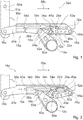
- Figure 1 schematically shows the aircraft seat device with the backrest impact securing device 14a in its locked position.
- the inertia module 16a is in its locked position at a rear end of the respective guide elements 28a, 50a, and the positive locking element 24a of the knee joint 22a engages in the positive locking element 48a of the inertial module 16a, whereby the knee joint 22a is also held in its locked position.
- the articulated arms 40a, 42a are aligned with one another and hold the bolt 36a in its locking position at the rear end of the guide elements 26a.
- the seat component 12a is rigidly coupled to the backrest 10a via the backrest impact securing device 14a. If, in the event of a crash, there is a delay in the opposite direction of flight 66a, to which the backrest impact securing device 14a is aligned in parallel, the housing element 20a coupled to the stand unit is decelerated and the inertia module 16a mounted axially in the housing element 20a is deflected out of its locked position by its inertia and moved toward the front end of the housing member 20a.
- the interlocking element 48a of the inertia module 16a initially releases from the interlocking element 24a of the knee joint 22a, as a result of which the knee joint 22a is decoupled from the inertia module 16a.
- the knee joint 22a is deflected downward via the deflection unit 34a and the joint arms 40a, 42a are thus deflected from one another in alignment.
- the inertia module 16a passes over the actuation elevation 60a with the actuation surface 64a and thus deflects the second articulated arm 42a downward.
- the bolt 36a in the guide elements 26a is released and the bolt 36a can move in the axial direction together with the connecting element 18a in the guide elements 26a (cf. Figure 2 ).
- the backrest 10a is now at least partially decoupled from the seat component 12a.
- the backrest 10a Due to the partial decoupling of the backrest 10a from the seat component 12a, the backrest 10a can rotate about the bearing point 68a, by means of which the backrest 10a is pivotably mounted. Due to inertia in the event of a crash, a large part of the backrest 10a is accelerated in the direction of flight 66a. The majority of the backrest 10a moves in the direction of flight 66a in the event of a crash. Due to the inertia and due to the pivotable mounting of the backrest 10a around the bearing point 68a, a lower region of the backrest 10a moves against the flight direction 66a.
- the seat bottom 58a is also moved against the direction of flight 66a.
- the delay element 30a which counteracts the movement of the housing element 20a, brakes the movement of the backrest 10a and thus also a movement of the seat bottom 58a against the direction of flight 66a.
- a position of the backrest safety device 14a during a crash is shown in FIG Figure 3 shown.
- Figure 4 shows a maximum displacement of the housing element 20a to the bolt 36a and the connecting element 18a.
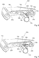
- the Figures 6 and 7 show an aircraft seat device according to the invention in a second embodiment.
- the aircraft seat device is part of a partially illustrated aircraft seat 32b.
- the aircraft seat device comprises a backrest 10b.
- the backrest 10b is provided so that a person sitting on the aircraft seat 32b, of which the aircraft seat device is part, can support his back on the backrest 10b.
- the aircraft seat device further comprises a seat component 12b.
- the aircraft seat device includes a backrest impact safety device 14b.
- the backrest impact securing device 14b is provided to partially decouple the backrest 10b from the seat component 12b in at least one operating state.
- the backrest impact securing device 14b comprises an inertia module 16b and a housing element 20b, in which the inertia module 16b is axially displaceably mounted.
- the inertia module 16b like the inertia module from the first exemplary embodiment, is intended to be deflected from a locking position in the event of a crash.
- the housing element 20b is essentially of the same design as the housing element from the first exemplary embodiment.
- the backrest impact securing device 14b comprises a connecting element 18b.
- the connecting element 18b is provided to be coupled to the seat component 12b.
- the connecting element 18b connects the backrest safety device 14b to the seat component 12b.
- the connecting element 18b is connected to the backrest safety device 14b.
- the backrest impact securing device 14b has two guide elements 26b.
- the guide elements 26b are designed as guide grooves.
- the backrest impact securing device 14b comprises a bolt 36b which connects the connecting element 18b to the backrest impact securing device 14b via the guide elements 26b.
- the bolt 36b is supported in the guide elements 26b.
- the backrest impact securing device 14b comprises a locking element 70b.
- the locking element 70b is pivotally mounted in a front region of the housing element 20b via a pin element 72b.
- the locking element 70b has a locking position ( Figure 6 ). In the locking position, the locking element 70b locks the bolt 36b in its locking position with a form-locking element 74b.
- the form-locking element 74b is arranged at a front free end of the locking element 70b.
- the locking element 70b has a guide element 76b.
- the guide element 76b is designed as a groove.
- the Guide element 76b of the locking element 70b is coupled to a pin element of the inertia module 16b, not shown in any more detail.
- the guide element 76b of the locking element 70b is oriented obliquely to guide elements 28b, via which the inertia module 16b is mounted in the housing element 20b.
- the pin element of the inertia module 16b in the guide element 76b of the locking element 70b shifts.
- the blocking element 70b is pivoted with the front free end to the housing element 20b.
- the locking element 70b releases the bolt 36b and the latter can be displaced in the guide elements 26b in which the bolt 36b is slidably mounted.
- FIG 8 shows part of an aircraft seat device according to the invention in a third embodiment.
- the aircraft seat device includes a backrest impact safety device 14c.
- the backrest impact securing device 14c is provided to partially decouple a backrest from a seat component in at least one operating state.
- the shows Figure 8 only a housing element 20c of the backrest impact securing device 14c in a sectional view.
- the backrest safety device 14c comprises a plurality of delay elements 30c. In contrast to the other exemplary embodiments, only the delay elements 30c differ from the delay elements of the other exemplary embodiments.
- the delay elements 30c are each designed as a web that spans a guide element 26c designed as a groove.
- the delay elements 30c designed as a web extend transversely to a main direction of extension of the guide element 26c and connect one side of the guide element 26c designed as a groove to an opposite side of the guide element 26c.
- the delay elements 30c are each arranged at a distance from one another.
- a bolt, not shown, which is axially displaceably mounted in the guide element 26c and which couples the housing element 20c to the seat component, must destroy the delay elements 30c in order to move in the guide element 26c, as a result of which energy is dissipated and and the bolt and thus the backrest coupled to it Delay elements 30c are delayed. It is conceivable that the plurality of delay elements 30c have different resistances against destruction and thus a defined power reduction, i.e.
- the backrest impact securing device 14c has two holding elements 78c, which are arranged at a first end of the guide element 26c designed as a groove.
- the holding elements 78c are designed as hooks which protrude inwards into the guide element 26c designed as a groove.
- the bolt For displacement in the guide element 26c designed as a groove, the bolt must first destroy the holding elements 78c.
- Figure 9 shows a part of an aircraft seat device according to the invention in a fourth embodiment.
- the aircraft seat device includes a backrest impact safety device 14d.
- the backrest impact securing device 14d is provided to partially decouple a backrest from a seat component in at least one operating state.
- the backrest safety device 14d includes a delay element 30d. In contrast to the other exemplary embodiments, only the delay element 30d differs from the delay elements of the other exemplary embodiments.
- the delay element 30d is formed in one piece with a guide element 26d designed as a groove, in which a bolt for connecting a seat component designed as a transverse stiffening unit is axially displaceably mounted.
- the guide element 26d which forms the delay element 30c, is designed to taper.
- the guide element 26d has a taper in a direction in which the bolt moves in the event of a crash, the guide element 26d in this case having a width which is smaller than a width of the bolt.
- the bolt For the axial displacement in the guide element 26d, the bolt must widen the guide element 26d, which forms the deceleration element 30d in one piece. Due to the plastic deformation of the guide element 26d, which forms the delay element 30d, energy is dissipated and the bolt is decelerated.
- FIG 10 shows a part of an aircraft seat device according to the invention in a fifth embodiment.
- the aircraft seat device includes a backrest impact safety device 14e.
- the backrest impact securing device 14e is provided to secure a backrest in at least one operating state Partially decouple the seat component.
- the shows Figure 10 only a housing element 20e of the backrest impact securing device 14e in a sectional view.
- the backrest safety device 14e includes a plurality of delay elements 30e. Only the delay elements 30e differ from the delay elements of the other exemplary embodiments.
- the delay elements 30e are designed as tapering of a guide element 26e designed as a groove. In the area of the delay elements 30e, side edges of the guide element 26e designed as a groove each extend inwards toward one another.
- the guide element 26e which is designed as a groove, is narrowed in the region of the delay elements 30e.
- a bolt which is movably mounted in the guide element 26e has to bend up the delay elements 30e, which are designed as tapered portions, as a result of which kinetic energy can be reduced to deformation energy.
- the Figures 11 to 13 show an aircraft seat device according to the invention in a sixth embodiment.
- the aircraft seat device is part of a partially illustrated aircraft seat 32f.
- the aircraft seat 32f is part of an aircraft, not shown.
- the aircraft seat 32f is mounted in an assembled state in an aircraft cabin of the aircraft.
- the aircraft seat 32f has a stand unit.
- the aircraft seat 32f is mounted on a cabin floor of the aircraft cabin by means of the stand unit.
- the cabin floor forms an elevation level for the aircraft seat 32f.
- the aircraft seat 32f is designed as part of a row of seats which comprises more than one aircraft seat 32f, preferably at least three aircraft seats 32f.
- the aircraft seat 32f forms a seat direction.
- the seat direction is defined as the direction in which a passenger sits on the aircraft seat 32f.
- the seat direction is formed parallel to a flight direction 66f.
- the flight direction 66f is formed by a main extension of the aircraft cabin.
- the stand unit is designed as a common stand unit of the aircraft seats 32f of the row of aircraft seats.
- the aircraft seat device comprises a backrest 10f.
- the backrest 10f is provided so that a person sitting on the aircraft seat 32f, of which the aircraft seat device is a part, can support his back on the backrest 10f.
- the backrest 10f is arranged pivotably to the stand unit.
- the backrest 10f is pivotally articulated on a seat divider, not shown, via a bearing 68f.
- the aircraft seat device further includes a seat member 12f.
- the seat component 12f is designed as a transverse stiffening unit which is provided to stiffen the backrest 10f in the transverse stiffening unit direction.
- the seat component 12f designed as a transverse stiffening unit is provided to connect one side of the aircraft seat 32f, the part of which is the aircraft seat device, to the other side of the aircraft seat 32f.
- the seat component 12f which is designed as a transverse stiffening unit, extends between the seat dividers of the aircraft seat 32f, which are not shown in detail.
- the seat component 12f, which is designed as a transverse stiffening unit is rotatably mounted in the seat dividers (not shown).
- the seat component 12f designed as a transverse stiffening unit is intended to be rotated when the backrest 10f moves.
- the seat component 12f designed as a cross-stiffening unit is designed as a torsion element.
- the seat component 12f designed as a transverse stiffening unit is designed as a torsion tube.
- the aircraft seat device has a seat bottom 58f.
- the seat component 12f is designed as a seat bottom or a component of the seat structure.
- the seat bottom 58f forms a seat surface.
- the seat bottom 58f is coupled to the backrest 10f.
- the backrest 10f and the seat bottom 58f are connected to one another in an articulated manner.
- the backrest 10f and the seat bottom 58f are pivotally coupled to one another via a kinematics of the aircraft seat device, which are not shown in detail.
- the backrest 10f and the seat base 58f can be moved relative to one another in different positions and can be fixed in these different positions.
- the backrest 10f and the seat bottom 58f are preferably displaceable relative to one another in a stepless manner.
- the backrest 10f is rigidly connected to the seat bottom 58f or a seat structure in a normal operating state and the aircraft seat 32f only has one seat position.
- the aircraft seat device includes a backrest impact safety device 14f.
- the backrest impact securing device 14f is provided, at least in a normal operating state, for rigidly connecting the backrest 10f and the seat component 12f in a locked position.
- the normal operating state which reflects normal and correct use of the aircraft seat 32f
- forces can be transmitted from the backrest 10f into the seat component 12f via the backrest impact securing device 14f.
- the backrest impact safety device 14f, the backrest 10f and the seat component 12f rigidly connects in the locked position, forces can be transmitted to the front, ie in the direction of flight 66 and counter to the direction of flight 66.
- the backrest impact securing device 14f is provided to partially decouple the backrest 10f from the seat component 12f in at least one operating state. Due to the partial decoupling of the backrest 10f from the seat component 12f, the backrest 10f and the seat component 12f can make a relative movement to one another in the event of a crash, in order to reduce the risk of injury to a passenger sitting on the aircraft seat 32f. In particular in the event of a crash with a deceleration counter to the direction of flight 66f, the backrest impact safety device 14f decouples the backrest 10f from the seat component 12f.
- the backrest impact securing device 14f at least partially reduces the impact forces acting on the backrest 10f, which also reduces the force on a passenger who exerts the force on the backrest 10f.
- the backrest 10f and the seat component 12f embodied as a transverse stiffening unit are coupled to one another by means of the backrest impact securing device 14f.
- the backrest safety device 14f has a locked position and an unlocked position. In the locked position, the backrest impact safety device 14f is locked and the backrest 10f is firmly coupled to the seat component 12f. In the locked position of the backrest safety device 14f, the backrest 10f cannot move to the seat component 12f via the backrest safety device 14f.
- the backrest 10f In the unlocked position, the backrest 10f is decoupled from the seat component 12f and can be moved to the seat component 12f. In the unlocked position of the backrest safety device 14f, the backrest 10f can be pivoted to the seat component 12f by an advantageous angle.
- the backrest impact securing device 14f decouples the backrest 10f from the seat component 12f before the impact forces act on the backrest 10f.
- the backrest 10f is decoupled from the seat component 12f in the event of a crash before a passenger strikes the backrest 10f and transmits the impact forces to the backrest 10f.
- the backrest 10f is partially decoupled when the passenger hits the backrest 10f, that is to say when the impact forces from the seat component 12f act upon it, and can thus be moved to the seat component 12f before or during the impact of the passenger on the backrest 10f thus absorbing and / or advantageously deflecting part of the impact forces, so that an impact on the backrest 10f is less hard for the passenger.
- the backrest 10f is intended to be locked again in a locking position after the partial decoupling.
- the backrest 10f can be locked again in the locking position after the partial decoupling and the movement to the seat component 12f that has been carried out in the process.
- the locking position can be the same in which the backrest 10f is locked in the normal operating state, but it is also conceivable that the locking position in which the backrest 10f is locked again after the partial decoupling is different from the locking position in the normal operating state.
- the backrest 10f can be secured in the locked position again by a passenger after an adjustment from the locking position in the event of a crash, in order to enable a safe escape route in which the backrest 10f is not in the way.
- the backrest impact securing device 14f is intended to be brought into a locking position again after the partial decoupling and thereby to lock the backrest 10f back into the locking position after the partial decoupling.
- the aircraft seat device it would also be conceivable for the aircraft seat device to have a device which is separate from the backrest impact securing device 14f and is intended to bring the backrest 10f back into a locked position after the partial decoupling.
- the separately designed device is constructed in a similar way and functions as the backrest impact securing device 14f described below. In principle, it is also conceivable that the separately designed device only has the same effect as the backrest impact securing device 14f described below, but that its structure differs.
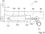
- the backrest impact safety device 14f comprises a housing 80f.
- the housing 80f is intended to house the backrest impact safety device 14f.
- the housing 80f is designed as a closed housing.
- the housing 80f is designed as a cylinder.
- the housing 80f formed as a cylinder has a central axis that corresponds to a main direction of extent of the housing 80f.
- the housing 80f encloses an interior.
- the housing 80f encloses the entire interior in an assembled state. This can advantageously prevent the ingress of liquids or dirt into the interior of the housing 80f and thus improve the reliability of the backrest impact safety device 14f. In principle, however, it is also conceivable for the housing 80f to be at least partially open.
- the housing 80f comprises a connection element 82f.
- the connecting element 82f is designed as a form-locking element and is provided for rigid connection to an equivalent connecting element.
- the connecting element 82f is arranged at a first axial end of the housing 80f and thus forms a first axial end of the backrest impact securing device 14f.
- the housing 80f can be rigidly connected to the backrest 10f via the connecting element 82f.
- the backrest impact safety device 14f is connected to the backrest 10f via the connecting element 82f of the housing 80f.
- the backrest impact securing device 14f comprises an element 84f which is mounted in an axially displaceable manner in the housing 80f.
- the element 84f is designed as a piston element.
- the element 84f designed as a piston element extends in the assembled state in the interior of the housing 80f.
- a first axial end of element 84f faces the first axial end of housing 80f.
- the element 84f extends from a second axial end of the housing 80f to beyond a center between the first end and the second end of the housing 80f.
- the element 84f is at least essentially rotationally symmetrical and has a central axis. At least one area of the element 84f arranged in the housing 80f is designed to be rotationally symmetrical.
- the central axis of the element 84f is aligned coaxially to the central axis of the housing 80f in the assembled state.
- the element 84f protrudes from the housing 80f.
- the housing 80f has a through opening 98f at the second axial end.
- the element 84f comprises a connection element 86f.
- the connecting element 86f is designed as a form-locking element and is provided for rigid connection to an equivalent connecting element.
- the element 84f can be rigidly connected to the seat component 12f via the connecting element 86f.
- the backrest impact safety device 14f is above the connecting element 86f of the element 84f connected to the seat component 12f.
- the connecting element 86f is arranged at a second axial end of the element 84f.
- the connecting element 86f thereby forms a second axial end of the backrest safety device 14f.
- the backrest impact securing device 14f has a stop 156f.
- the stop 156f is intended to limit the element 84f to a maximum position in the housing 80f.
- the stop 156f is formed by elevations which rise inwards in the interior of the housing 80f.
- the stop 156f limits movement of the element 84f in the housing 80f towards the first axial end of the housing 80f.
- the element 84f strikes the stop 156f.
- the element 84f has an elevation 158f which in the locked position strikes the stop 156f.
- the backrest safety device 14f has a locked position and an unlocked position. In principle, it is also conceivable that the backrest safety device 14f has at least two locking positions that differ from one another.
- the element 84f In the locked position of the backrest safety device 14f, the element 84f, which is axially displaceably mounted in the housing 80f, is rigidly connected to the housing 80f. The element 84f cannot be moved in the housing 80f in the locked position of the backrest impact securing device 14f.
- the unlocked position of the backrest safety device 14f the element 84f, which is axially displaceably mounted in the housing 80f, can move by a defined travel path.
- the element 84f can be moved out of the locked position of the backrest safety device 14f in a release direction which is directed away from the connecting element 82f of the housing 80f. This allows the backrest safety device 14f to be extended by moving the element 84f out of the locked position. By moving the element 84f out of the locking position in the release direction, a distance between the connecting element 82f of the housing 80f and the connecting element 86f of the element 84f is increased.
- the backrest impact protection device 14f has at least one locking module 88f, which locks the backrest impact protection device 14f in a locking position.
- the locking module decouples in the unlocked position 88f at least partially the backrest safety device 14f.
- the backrest safety device 14f can be transferred from the unlocked position into the locked position by means of the locking module 88f.
- the housing 80f and the axially displaceably mounted element 84f are coupled to one another via the locking module 88f in the locked position of the backrest impact securing device 14f.
- the locking module 88f has two locking elements 90f, 92f that can be deflected against an elastic force.
- the locking elements 90f, 92f are designed as pivotable lever elements.
- the locking elements 90f, 92f are arranged in the interior of the housing 80f.
- the locking elements 90f, 92f are designed as elongated lever elements which have a main direction of extension, which in the assembled state is aligned parallel to a main direction of extension of the housing 80f.
- the locking elements 90f, 92f each have a circular ring segment as a cross section orthogonal to their main direction of extension.
- the locking elements 90f, 92f are arranged mirror-inverted to one another in relation to a central axis of the cylindrical housing 80f.
- the locking elements 90f, 92f each have a bearing point 94f, 96f, via which the locking elements 90f, 92f are arranged pivotably in the housing 80f.
- the bearing points 94f, 96f each form a first, housing-side bearing element (not described in more detail), which is formed by the housing 80, and a second bearing element formed by the respective locking element 90f, 92f.
- the bearing elements are each designed as plain bearings. In principle, it would also be conceivable that roller bearings are used for mounting the locking elements 90f, 92f.
- the bearing points 94f, 96f are each arranged on a side facing the second axial end of the housing 80f. Via the bearing points 94f, 96f, a front axial end of the locking elements 90f, 92f, which in the assembled state is assigned to the second axial end of the housing 80f, can be pivoted outward into an open position.
- the two locking elements 90f, 92f are coupled to one another via a spring element 100f.
- the spring element 100f exerts a spring force on the locking elements 90f, 92f, which pushes the locking elements 90f, 92f away from one another in the rear axial end.
- the spring element 100f is designed as a spiral spring. In principle, it would also be conceivable for the spring element to be designed as another spring element that appears to be useful to the person skilled in the art.
- the spring element 100f presses the locking elements 90f, 92f into an idle state via its spring force.
- the locking elements 90f, 92f of the locking module 88f each have a form-locking element 102f, 104f at their front end.
- the interlocking elements 102f, 104f are each designed as a tooth profile, which is arranged on an inward-facing inside of the locking elements 90f, 92f. In principle, it is also conceivable that the positive locking elements 102f, 104f have a different shape.
- the interlocking elements 102f, 104f of the locking elements 90f, 92f form a part of the locking module 88f fixed to the housing.
- the form-locking elements 102f, 104f are fixedly coupled to the housing 80f via the pivotable mounting of the locking elements 90f, 92f.
- the element 84f has a correspondingly designed form-fitting element 106f.
- the form-fitting element 106f is designed as a toothing running around the element 84f, which is complementary to the tooth profiles of the form-fitting elements 102f, 104f of the locking elements 90f, 92f.
- the positive locking elements 102f, 104f engage in the positive locking element 106f, which is formed by the element 84f.
- the element 84f and the housing 80f are rigidly connected to one another via the locking elements 90f, 92.
- the spring element 100f presses the form-locking elements 102f, 104f into the form-locking element 106f via the deflection via the bearing points 94f, 96f.
- the locking module 88f is constructed in a different way and, for example, deflects the locking elements 90f, 92 in an unlocking position by an electromagnetic force and blocks it in a locking position by an electromagnetic force.
- the backrest safety device 14f comprises an inertia module 16f.
- the inertia module 16f is provided to at least partially unlock the backrest safety device 14f in the event of a crash. In the normal operating state of the backrest safety device 14f, the inertia module 16f is arranged in a locked position.
- the locked position of the inertia module 16f is formed by an area in which the inertia module 16 can be arranged without this partially unlocking the backrest impact securing device 14f.
- the inertia module 16f is formed by a mass element 108f, which is arranged axially displaceably in the interior of the housing 80f.
- the mass element 108f is arranged at a first axial end of the housing 80f.
- the mass element 108f has a cylindrical shape.
- the mass element 108f is mounted in the interior of the housing 80f via a slide bearing.
- the mass element 108f has a flat wall at its first end, which in the assembled state faces the first axial end of the housing 80f.
- the mass element 108f has an actuating contour 110f.
- the actuating contour 110f is concave.
- the actuating contour 110f has a conical shape.
- the actuating contour 110f extends inward from the first end of the mass element 108f from a radial outer region in the direction of the second end of the mass element 108f.
- the actuating contour 110f is provided to deflect the locking elements 90f, 92f from their rest position.
- the mass element 108f for deflecting the locking elements 90f, 92f is provided to press the locking elements 90f, 92f towards each other at their rear ends.
- the actuating contour 110f forms a different shape, such as, for example, a spherical shape, an elliptical shape or a mixed shape.
- a triggering delay can be set by designing the actuating contour 110f and by the contour of the locking elements 90f, 92f and the weight of the mass element 108f.
- a release speed can also be set.
- the inertia module 16f is provided for unlocking the backrest safety device 14f to deflect the locking elements 90f, 92f at least temporarily.
- the inertia module 16f for unlocking the backrest safety device 14f is provided to be deflected from its locked position.
- the inertia module 16f is intended to be deflected from a locking position before the impact forces act. If the inertia module 16f is deflected from its locking position, the backrest impact securing device 14f moves from the locking position into the unlocking position.
- the inertia module 16f forms the mass element 108f.
- the mass element 108f is provided to give the inertia module 16f a mass, which, due to its inertia in a crash, deflects the inertia module 16f in the backrest safety device 14f from its locking position and at least partially unlocks the backrest safety device 14f by deflecting the locking elements 90f, 92f.
- the backrest impact securing device 14f has at least one spring element 112f, which is provided to hold the inertial module 16f in its locked position.
- the spring element 112f is arranged in the interior of the housing 80f.
- the spring element 112f is functionally arranged between the housing 80f and the inertia module 16f.
- the spring element 112f is supported on the housing 80f and exerts a spring force on the inertia module 16f which is axially displaceably mounted in the housing 80f.
- the spring element 112f abuts the mass element 108f at a first end. With a second end, the spring element 112f is supported on an inner side of the housing 80f via a connection region (not shown in more detail).
- the spring element 112f is arranged between the second end of the housing 80f and the mass element 108f of the inertia module 16f.
- the spring element 112f is designed as a compression spring. As a result, the mass element 108f of the inertia module 16f in the housing 80f is pressed toward its first position in the locked position. In the event of a crash, the mass element 108f must move in the triggering direction against the spring force of the spring element 112f in order to unlock the backrest impact safety device 14f.
- the spring element 112f is designed as a spiral spring. In principle, it is also conceivable that the spring element 112f is designed as another spring element that appears to be useful to the person skilled in the art, such as a gas pressure spring, a magnetic and / or electrical spring element or a spring element that generates a restoring force by compressing a fluid.
- the backrest safety device 14f comprises a delay element 30f.
- the delay element 30f is for absorbing inertial energy of the backrest 10f after the partial decoupling of the backrest safety device 14f provided.
- the deceleration element 30f absorbs at least some of the inertial forces which act on the backrest 10f.
- the delay element 30f is provided to be plastically deformed.
- the delay element 30f is arranged in the interior of the housing 80f.
- the delay element 30f is functionally arranged between the element 84f and the housing 80f.
- the delay element 30f is provided to brake a relative movement of the element 84f to the housing 80f after the partial decoupling before an end stop.
- the delay element 30f is designed as a plastically deformable sleeve.
- the delay element 30f encloses the piston-like element 84f.
- the element 84f has a driving element 114f.
- the driving element 114f is firmly connected to the element 84f. In principle, it is also conceivable that the driving element 114f is formed in one piece with the element 84f.
- the delay element 30f is arranged between the driver element 114f and the second end of the housing 80f.
- the driving element 114f takes the delay element 30f with it until it abuts against an axial inner wall on the second end of the housing 80f.
- the delay element 30f is clamped between the entraining element 114f and the inner wall at the second end of the housing 80f and plastically deformed. Due to the plastic deformation of the delay element 30f, a kinetic energy of the backrest 10f is converted into forming work and thereby destroyed.
- the one adjustment of the element 84f to the housing 80f and thus an adjustment of the backrest 10f after the partial decoupling is delayed before a maximum adjustment and is not braked abruptly.
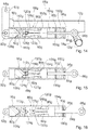
- FIG 11 schematically shows the aircraft seat device with the backrest impact securing device 14f in its locked position.
- the inertia module 16f is in its locked position.
- the housing 80f is rigidly connected to the element 84f by the locking module 88f.
- the connecting element 82f, which is coupled to the backrest 10f, and the connecting element 86f, which is coupled to the seat component 12f coupled is rigidly connected to one another. Forces can be transmitted between the backrest 10f and the seat component 12f via the connection elements 82f, 86f via the backrest impact securing device 14f.
- the housing 80f coupled to the stand unit via the backrest 10f is decelerated and the inertia module 16f mounted axially in the housing 80f is characterized by its inertia deflected its locking position and moved against the spring force of the spring element 112f in the direction of the second end of the housing 80f.
- the locking elements 90f, 92f are pivoted out of their rest position and the positive connection between the locking elements 90f, 92f coupled to the housing 80f and the element 84f via the positive locking elements 102f, 104f, 106f is canceled.
- the backrest safety device 14f is thereby partially unlocked.
- Element 84f can slide in housing 80f relative to housing 80f.
- the backrest 10f is now at least partially decoupled from the seat component 12f.
- the backrest 10f Due to the partial decoupling of the backrest 10f from the seat component 12f, the backrest 10f can rotate about the bearing point 68f, by means of which the backrest 10f is pivotably mounted. Due to inertia in the event of a crash, a large part of the backrest 10f is accelerated in the direction of flight 66f. The majority of the backrest 10f moves in the direction of flight 66f in the event of a crash. Due to the inertia and due to the pivotable mounting of the backrest 10f around the bearing point 68f, a lower region of the backrest 10f moves counter to the direction of flight 66f.
- the delay element 30f is carried along with the element 84f via the driving element 114f and is also moved relative to the housing 80f.
- the delay element 30f is clamped and deformed by the relative movement between the housing 80f and the element 84f between the driving element 114f and the housing 80f.
- the delay element 30f delays the relative movement between the housing 80f and the element 84f and thereby the pivoting movement of the backrest 10f.
- the backrest impact securing device 14f is intended to be brought into a locking position again after the partial decoupling.
- the backrest 10f can be locked again after an adjustment during the crash and an escape route can advantageously be kept free for a passenger.
- the backrest 10f is pivoted with its upper region forward in the direction of flight 66f. If the backrest 10f is pivoted backwards again, the housing 80f is displaced again in the direction of flight 66f and thus moves relative to the element 84f.
- the locking elements 90f, 92f held in their rest position by the spring element 100g are deflected outward again by the oblique toothing of the form-locking element 106f, which is formed by the element 84f.
- the interlocking elements 102f, 104f can be brought back into engagement with the interlocking element 106f of the element 84f.
- the housing 80f can again be rigidly coupled to the element 84f and the backrest impact securing device 14f can thereby be locked again.
- the Figures 14 to 16 show an aircraft seat device according to the invention in a seventh embodiment.
- the aircraft seat device is part of a partially illustrated aircraft seat 32g.
- the aircraft seat 32g is part of an aircraft, not shown.
- the aircraft seat 32g is mounted in an assembled state in an aircraft cabin of the aircraft.
- the aircraft seat device comprises a backrest 10g.
- the backrest 10g is provided so that a person sitting on the aircraft seat 32g, of which the aircraft seat device is part, can support his back on the backrest 10g.
- the backrest 10g is pivotally connected to a seat divider, not shown, via a bearing 68g.
- the aircraft seat device further comprises a seat component 12g.
- the seat component 12g is as a transverse stiffening unit is formed, which is intended to stiffen the backrest 10g in the transverse stiffening unit transverse direction.
- the seat component 12g designed as a transverse stiffening unit is provided to connect one side of the aircraft seat 32g, the part of which is the aircraft seat device, to the other side of the aircraft seat 32g.
- the aircraft seat device has a seat bottom 58g.
- the seat component 12g is designed as a seat bottom or a component of the seat structure.
- the seat bottom 58g forms a seat surface.
- the seat bottom 58g is coupled to the backrest 10g.
- the aircraft seat device includes a backrest impact safety device 14g.
- the backrest impact securing device 14g is provided, at least in a normal operating state, for rigidly connecting the backrest 10g and the seat component 12g in a locked position.
- a normal operating state which depicts normal and correct use of the aircraft seat 32g
- forces can be transmitted from the backrest 10g into the seat component 12g via the backrest impact securing device 14g.
- the backrest impact securing device 14g is provided to partially decouple the backrest 10g from the seat component 12g in at least one operating state.
- the backrest 10g and the seat component 12g can exert a relative movement in the event of a crash, in order to reduce the risk of injury to a passenger sitting on the aircraft seat 32g.
- the backrest impact securing device 14g decouples the backrest 10g from the seat component 12g before the impact forces act on the backrest 10g.
- the backrest 10g is intended to be locked again in a locking position after the partial decoupling.
- the backrest 10g can be locked again in the locking position after the partial decoupling and the movement to the seat component 12g which has been carried out in the process.
- the locking position can be the same in which the backrest 10g is locked in the normal operating state, but it is also conceivable that the locking position in which the backrest 10g is locked again after the partial decoupling is different from the locking position in the normal operating state.
- the backrest impact securing device 14g comprises a housing 80g.
- the housing 80g is intended to house the backrest impact safety device 14g.
- the housing 80g comprises a connection element 82g.
- the connecting element 82g is designed as a form-locking element and is provided for rigid connection to an equivalent connecting element.
- the connecting element 82g is arranged at a first axial end of the housing 80g and thus forms a first axial end of the backrest impact securing device 14g.
- the housing 80g can be rigidly connected to the backrest 10g via the connecting element 82g.
- the backrest impact securing device 14g comprises an element 84g which is mounted in an axially displaceable manner in the housing 80g.
- the element 84g is designed as a piston element.
- the element 84g designed as a piston element extends in the assembled state in the interior of the housing 80g. In the assembled state, a first axial end of the element 84g faces the first axial end of the housing 80g. At a second axial end of the housing 80g, which is opposite the first axial end of the housing 80g, the element 84g protrudes from the housing 80g.
- the element 84g comprises a connecting element 86g.
- the connecting element 86g is designed as a form-locking element and is provided for rigid connection to an equivalent connecting element.
- the element 84g can be rigidly connected to the seat component 12g via the connecting element 86g.
- the backrest impact securing device 14g has a stop 156g.
- the stop 156g is intended to limit the element 84g to a maximum position in the housing 80g.
- the stop 156g is formed by elevations which rise inwards in the interior of the housing 80g.
- the stop 156g is in particular formed by a bushing which is introduced into the interior of the housing 80g.
- the stop 156g limits movement of the element 84g in the housing 80g towards the first axial end of the housing 80g. In the locked position, the element 84g strikes the stop 156g.
- the backrest safety device 14g has at least one locking module 88g, which locks the backrest safety device 14g in a locked position.
- the locking module 88g of the backrest safety device 14g differs from the locking module of the corresponding backrest safety device from the sixth embodiment of FIG Figures 11 to 13 .
- the locking module 88g has two locking elements 90g, 92g, which are designed as piston-fixed, elastically deformable levers.
- the Locking elements 90g, 92g are formed in one piece with the element 84g.
- the locking elements 90g, 92g are formed from an elastically deformable material.
- the locking elements 90g, 92g extend from the element 84g in the direction of a first end of the housing 80g.
- the locking elements 90g, 92g are arranged at a distance from one another.
- the locking elements 90g, 92g are each connected to the element 84g with a first end which faces the element 84g. In the direction of their second ends, which face away from the element 84g, the locking elements 90g, 92g have an increasing distance.
- the two locking elements 90g, 92g together form a form-locking element 116g in the region of their second ends.
- the form-locking element 116g is formed by two notches 120g, 122g facing one another in the inner sides of the locking elements 90g, 92g.
- the notches 120g, 122g in the locking elements 90g, 92g face each other.
- the notches 120g, 122g are made at an equal distance from the element 84 in the respective locking element 90g, 92g.
- the two notches 120g, 122g form a triangular shape in an undeflected state of the locking elements 90g, 92g.
- a tip of the triangular form-locking element 116g is directed in the direction of the element 84g.
- the locking module 88g has a form-locking element 124g fixed to the housing.
- the form-locking element 124g is rigidly connected to the housing 80g.
- the form-locking element 124g extends across the interior of the housing 80g.
- the interlocking element 124g is designed to be equivalent to the interlocking element 116g formed by the locking elements 90g, 92g.
- the form-locking element 124g has a triangular cross section. In principle, it is also conceivable that the form-locking element 124g has a different cross-section, such as a semicircular shape, a circular shape or an elliptical shape.
- the corresponding form-locking element 116g formed by the locking elements 90g, 92g would accordingly be equivalent.
- the form-locking element 124g is formed by a triangular-shaped bolt which is guided through the interior of the housing 80g. The bolt that forms the form-locking element 124g is firmly connected to the housing 80g.
- the locking elements 90g, 92g embrace the form-locking element 124g.
- the positive locking element 124g is arranged in the locking position in the notches 120g, 122g of the locking elements 90g, 92g forming the positive locking element 116g.
- the form-locking element 124g and the form-locking element 116g are form-fitting connected with each other.
- the backrest safety device 14g is locked and a force can be transmitted via the backrest safety device 14g between the backrest 10g and the seat component 12g.
- the backrest safety device 14g comprises an inertia module 16g.
- the inertia module 16g is provided to at least partially unlock the backrest safety device 14g in the event of a crash.
- the inertia module 16g is configured essentially the same as the inertia module from the sixth exemplary embodiment in FIG Figures 11 to 13 .
- the inertia module 16g is formed by a mass element 108g, which is arranged axially displaceably in the interior of the housing 80g.
- the mass element 108g is arranged at a first axial end of the housing 80g.
- the mass element 108g has a differently shaped actuation contour 110g.
- the actuating contour 110g is convex.
- the actuating contour 110g has a convex conical shape.
- the actuating contour 110g extends inward from a first end of the mass element 108g, which faces the locking elements 90g, 92g, from a radial outer region in the direction of the locking elements 90g, 92g.
- the inertia module 16g is provided for releasing the positive connection between the form-locking elements 116g, 124g.
- the convex wedge-shaped actuating contour 110g is provided to push the locking elements 90g, 92g apart, in order to release the form-locking element 124 fixed to the housing from the wrapping of the form-locking element 116g formed by the locking elements 90g, 92g.
- the actuating contour 110g is provided to deflect the locking elements 90g, 92g from their rest position.
- the mass element 108g is provided for deflecting the locking elements 90g, 92g to push the locking elements 90g, 92g apart at their second end.
- the backrest impact securing device 14g has at least one spring element 112g, which is provided to hold the inertial module 16g in its locked position.
- the backrest safety device 14g comprises a delay element 30g.
- the delay element 30g is for receiving Inertia energy of the backrest 10g is provided after the partial decoupling of the backrest safety device 14g.
- the delay element 30g is configured in the same way as the corresponding delay element from the backrest safety device from the sixth exemplary embodiment of FIG Figures 11 to 13 .
- the delay element 30g differs from the corresponding delay element from the backrest safety device from the sixth exemplary embodiment in FIG Figures 11 to 13 .
- the delay element 30g is designed as a damping element.
- the delay element 30g designed as a damping element, is intended to absorb kinetic energy without plastic deformation.
- the delay element 30g is designed as a gas pressure spring.
- the delay element 30g is provided to absorb energy by flowing a fluid.
- the delay element 30g has an aperture 150g which separates two chambers 152g, 154g from one another.
- the aperture 150g is firmly connected to the element 84g.
- the orifice 150g separates the two chambers 152g, 154g in the interior of the housing from the element 84g radially on the inside to the housing 80g radially on the outside.
- the orifice 150g has a plurality of through holes, not shown, through which the two chambers 152g, 154g separated from the orifice 150g are connected to one another in terms of fluid technology.
- a fluid can pass from one chamber 152g into the other chamber 154g through the through holes.
- the fluid can be a gas or a liquid.
- the through holes are closed in a normal state by membranes, which are destroyed in a crash by the movement of the element 84g and the fluid and thus expose the through holes.
- the chamber 152g is reduced by the orifice 150g and the fluid arranged in the chamber flows through the through openings of the orifice 150g into the chamber 154g. As a result, energy is reduced and the backrest 10g is delayed.
- An operation of the delay element 30g in the event of a crash corresponds to that of the previous exemplary embodiment.
- the backrest impact securing device 14g can be locked into the locking position again after being partially uncoupled.
- the element 84g is moved by moving the backrest 10g moved relative to the housing 80g, so that the form-fitting element 116g of the locking elements 90g, 92g and the form-fitting element 124g fixed to the housing come into engagement again.
- the locking elements 90g, 92g are again pressed over the form-locking element 124g and snap back into the form-locking element 124g with their notches 120g, 122g by a restoring force generated by the deflection of the locking elements 90g, 92g.
- the backrest impact securing device 14g is again in the locked position and the backrest 10g is locked again.
- FIGS 17 to 20 show an aircraft seat device according to the invention in an eighth embodiment.
- the aircraft seat device is part of an aircraft seat, not shown.
- the aircraft seat device comprises a backrest and a seat component in accordance with the preceding exemplary embodiments, which are not described in more detail here.
- the seat component is designed as a cross stiffening unit which is provided to stiffen the backrest in the cross stiffening unit cross direction.
- the aircraft seat device includes a backrest impact safety device 14h.
- the backrest impact securing device 14h is provided, at least in a normal operating state, for rigidly connecting the backrest and the seat component in a locking position.
- the backrest impact securing device 14h is connected to the backrest and the seat component in accordance with the backrest impact securing devices of the preceding exemplary embodiments.
- the backrest impact securing device 14h is provided to partially decouple the backrest from the seat component in at least one operating state.
- the backrest impact securing device 14h decouples the backrest from the seat component before the impact forces act on the backrest.
- the backrest is intended to be locked again in a locking position after the partial decoupling.
- the backrest safety device 14h includes a housing 80h.
- the housing 80h is provided for the backrest impact safety device 14h to surround.
- the housing 80h comprises a connection element, not shown, via which the housing 80h is coupled to the seat component in the assembled state.
- the backrest impact securing device 14h comprises an element 84h which is mounted in an axially displaceable manner in the housing 80h.
- the element 84h is designed as a piston element.
- the element 84h designed as a piston element extends in the assembled state into the interior of the housing 80h.
- the element 84h comprises a connection element, not shown, via which the element 84h is coupled to the backrest in the assembled state.
- the backrest impact securing device 14h has a locking module 88h, which locks the backrest impact securing device 14h in a locking position.
- the locking module 88h of the backrest safety device 14h differs from the locking module of the corresponding backrest safety device from the previous exemplary embodiments.
- the locking module 88h comprises a coupling element 118h.
- the coupling element 118h is designed as a ball.
- the housing 80h and the element 84h are connected to one another in a locked position via the coupling element.
- the element 84h has a recess 126h in which the coupling element 118h designed as a ball is arranged in the locked position.
- the recess 126h is not drawn to scale in the figures for the sake of clarity.
- the recess 126h is not as deep as shown in the figures in order to prevent the coupling element 118h from tilting.
- the housing 80h forms a shoulder 128h. In the locked position, the coupling element 118h rests positively on the recess 126h and the shoulder 128h. As a result, the housing 80h and the element 84h are connected to one another in the locked position via the coupling element 118h.
- the backrest safety device 14h comprises an inertia module 16h. To secure the coupling element 118h in the locked position, the backrest impact securing device 14h has an inertia module 16h. The inertia module 16h is further provided to at least partially unlock the backrest safety device 14h in the event of a crash.
- the inertia module 16h is formed by a mass element 108h, which is arranged axially displaceably in the interior of the housing 80h. In the locked position, the inertia module 16h is arranged above the coupling element 118h and thus holds the coupling element 118h in the recess 126h of the element 84h. The positive connection between the housing 80h and the element 84h is secured via the inertia module 16h. If the inertia module 16h is deflected against a direction of flight in the event of a crash, the inertia module 16h releases the coupling element 118h and the positive connection between the housing 80h and the element 84h via the coupling element 118h is released.
- the backrest impact safety device 14h is thereby at least partially unlocked and the element 84h can be axially displaced in the housing 80h.
- the backrest impact securing device 14h it is also conceivable for the backrest impact securing device 14h to have further coupling elements 118h and depressions 126h, via which the housing 80h and the element 84h are connected to one another in a form-fitting manner.
- the backrest impact securing device 14h has a spring element 112h, which is provided to hold the inertia module 16h in its locked position.
- the spring element 112h is designed in accordance with the previous exemplary embodiments.
- the spring element 112h is designed as a spiral spring.
- the spring element 112h is arranged between the inertia module 16h and a support wall 130h of the element 84h. In the locked position, the element 84h rests with the support wall 130h on an inner wall of the housing 80h.
- the housing 80h has an opening 132h on its circumference. In principle, it is also conceivable for the housing 80h to have further of these openings 132h on its periphery, for which the following description can also be used.
- the opening 132h is arranged at a rear end of the housing 80h.
- the support wall 130h extends into the opening 132h of the housing 80h.
- the backrest impact securing device 14h has a leaf spring element 134h.
- the leaf spring element 134h is firmly connected to an outside of the housing 80h and projects into the opening 132h. With a loose end, the leaf spring element 134h lies in the locking position on the support wall 130h of the element 84h (see Figure 17 ).
- the support wall 130h has a predetermined breaking point 136h at a height of a lower edge of the opening 132h.
- the area above the predetermined breaking point 136h is provided for breaking off at an edge 138h of the opening 132h during a crash, when the element 84h is axially displaced within the housing 80h (see Figure 19 ). If the area above the predetermined breaking point 136h is broken off, the support wall 130h can move within the housing 80h.
- the predetermined breaking point 136c it would also be conceivable for the support wall 130h to have a joint which extends the area designed pivotable above the joint. It would be conceivable for the support wall to have a film hinge instead of the predetermined breaking point, through which the upper region can be folded down if it abuts the edge 138h of the opening 132.
- the backrest impact securing device 14h has a stop 156h.
- the stop 156h is provided to limit the element 84h to a maximum position in the housing 80h.
- the stop 156h is formed by the support wall 130h, which is supported on the housing 80h.
- the stop 156h limits movement of the element 84h in the housing 80h towards the rear end of the housing 80h. In the locked position, the stop 156h strikes the rear end of the housing 80h.
- the inertia module 16h is first deflected against the spring force of the spring element 112h. Due to the deflection of the inertia module 16h, the coupling element 118h is released and the positive connection between the housing 80h and the element 84h is released via the coupling element 118h.
- the acceleration required to unlock the backrest impact securing device 14h can be designed in a particularly simple and advantageous manner, since only the mass of the mass element 108h and the spring force of the spring element 112h influence this required acceleration.
- the element 84h is displaced in the crash against the flight direction to the housing 80h by the pivoting of the backrest.
- the backrest safety device 14h comprises a delay element 30h.
- the delay element 30h absorbs at least some of the inertial forces that act on the backrest.
- the delay element 30h is provided to be plastically deformed.
- the delay element 30h is arranged between the inertia module 16h and the support wall 130h.
- the delay element 30h is clamped and deformed between the inertia module 16h, which is supported on the shoulder 128h of the housing 80h and the support wall 130h, whereby it absorbs energy (see Figure 19 ).
- the backrest can again be locked into a locking position via the backrest impact securing device 14h to be brought.
- the element 84h is pushed back into the housing 80h.
- the support wall 130h of the element 84h is clamped between an inner wall of the housing 80h and the leaf spring element 134h and thus locked in the locked position.
- the Figure 21 shows an aircraft seat device according to the invention in a ninth embodiment.
- the aircraft seat device is part of a partially illustrated aircraft seat 32i.
- the aircraft seat 32i is part of an aircraft, not shown.
- the aircraft seat 32i is mounted in an assembled state in an aircraft cabin of the aircraft.
- the aircraft seat device comprises a backrest 10i.
- the backrest 10i is provided so that a person sitting on the aircraft seat 32i, of which the aircraft seat device is part, can support his back on the backrest 10i.
- the backrest 10i is pivotally connected to a seat divider, not shown, via a bearing 68i.
- the aircraft seat device further comprises a seat component 12i.
- the seat component 12i is designed as a cross stiffening unit, which is provided to stiffen the backrest 10i in the cross stiffening unit transverse direction.
- the seat component 12i designed as a transverse stiffening unit is provided to connect one side of the aircraft seat 32i, the part of which is the aircraft seat device, to the other side of the aircraft seat 32i.
- the aircraft seat device has a seat bottom 58i.
- the seat component 12i is designed as a seat bottom or a component of the seat structure.
- the seat bottom 58i forms a seat surface.
- the seat bottom 58i is coupled to the backrest 10i.
- the aircraft seat device includes a backrest impact safety device 14i.
- the backrest impact securing device 14i is provided, at least in a normal operating state, for rigidly connecting the backrest 10i and the seat component 12i in a locked position.
- the normal operating state which depicts normal and correct use of the aircraft seat 32i
- forces can be transmitted from the backrest 10i into the seat component 12i via the backrest impact securing device 14i.
- the backrest impact securing device 14i is provided to partially decouple the backrest 10i from the seat component 12i in at least one operating state.
- the backrest safety device 14i is designed like a backrest safety device described in the previous exemplary embodiments.
- the aircraft seat device comprises an additional force element 140i.
- the additional force element 140i is provided to accelerate the backrest 10i at least temporarily immediately before the partial decoupling.
- the additional force element 140i is designed as a gas pressure spring.
- the additional force element 140i is designed as a mechanical spring element or an electro-magnetic spring element.
- the additional force element 140i is designed as a pyrotechnic element that provides its additional force through a pyrotechnic effect.
- the additional force element 140i is functionally arranged between the backrest 10i and the seat component 12i.
- the additional force element 140i is functionally arranged between a housing 80i of the backrest safety device 14i and an element 84i movably mounted in the housing 80i.
- the additional force element 140i has a first connection point 142i, via which the additional force element 140i is rigidly connected to the housing 80i.
- the connection point 142i is arranged on a housing 144i of the additional force element 140i.
- the additional force element 140i has a second connection point 146i, via which the additional force element 140i is rigidly connected to the element 84i of the backrest safety device 14i.
- the connection point 146i is arranged on an extendable piston 148i of the additional force element 140i.
- the additional force element 140i In the locked position of the backrest safety device 14i, the additional force element 140i is arranged pretensioned between its two connection points 142i, 146i.
- the additional force element 140i provides a spring force that pushes apart the mutually movable parts of the backrest impact securing device 14i, such as in particular the housing 80i and the element 84i.
- the additional force element 140i In the locked state of the backrest impact securing device 14i, the additional force element 140i has no influence on the system. If the backrest impact safety device 14i is unlocked during a crash, the additional force element 140i can provide its spring force and thus push the element 84i and the housing 80i apart.
- the spring force provided by the additional force element 140i acts thereby in the same direction as the deceleration force during the crash.
Claims (17)
- Dispositif de siège d'avion avec au moins un dossier (10a ; 10b ; 10f ; 10g ; 10i), avec au moins un composant structurel de siège (12a ; 12b ; 12f ; 12h ; 12i) couplé avec le dossier (10a ; 10b ; 10f ; 10g ; 10i) et avec un dispositif sauvegarde-choc de dossier (14a ; 14b ; 14f ; 14g ; 14h) qui est configuré, par le biais d'un découplage partiel du dossier (10a ; 10b ; 10f ; 10g ; 10i) du composant structurel de siège (12a ; 12b ; 12f ; 12h ; 12i), pour réduire au moins partiellement des forces d'impact sur le dossier (10a ; 10b ; 10f ; 10g ; 10i) au moins en cas de crash,
le dispositif sauvegarde-choc de dossier (14a ; 14b ; 14f ; 14g ; 14h) étant prévu à découpler le dossier (10a ; 10b ; 10f ; 10g ; 10i) du composant structurel de siège (12a ; 12b ; 12f ; 12h ; 12i) avant un effet des forces d'impact,
le dispositif sauvegarde-choc de dossier (14a ; 14b ; 14f ; 14g ; 14h) comprenant au moins un module d'inertie (16a ; 16b ; 16f ; 16g ; 16h), qui est prévu à découpler le dispositif sauvegarde-choc de dossier (14a ; 14b ; 14f ; 14g ; 14h ; 14i) au moins en cas de crash,
caractérisé en ce que le dispositif sauvegarde-choc de dossier (14a) comporte au moins une articulation-genou (22a) qui est prévue, en état opératif normal, à être couplée avec le module d'inertie (16a). - Dispositif de siège d'avion selon la revendication 1,
caractérisé en ce que le module d'inertie (16a ; 16b ; 16f ; 16g ; 16h) est prévu, au moins en état opératif normal, à verrouiller le dispositif sauvegarde-choc de dossier (14a ; 14b ; 14f ; 14g ; 14h). - Dispositif de siège d'avion selon l'une quelconque des revendications 1 ou 2,
caractérisé en ce qu', en cas de crash, pour un déverrouillage du dispositif sauvegarde-choc de dossier (14a ; 14b), le module d'inertie (16a ; 16b ; 16f ; 16g, 16h) est prévu à être défléchi d'une position de verrouillage. - Dispositif de siège d'avion au moins selon la revendication 1,
caractérisé en ce qu', en cas de crash, le module d'inertie (16a ; 16b, 16f ; 16g ; 16h) est prévu à être défléchi d'une position de verrouillage avant un effet des forces d'impact. - Dispositif de siège d'avion selon l'une quelconque des revendications précédentes,
caractérisé en ce que le dispositif sauvegarde-choc de dossier (14a ; 14b) comporte au moins un élément de raccordement (18a ; 18b) prévu à être couplé avec le composant structurel de siège (12a ; 12b). - Dispositif de siège d'avion selon la revendication 1,
caractérisé en ce que le dispositif sauvegarde-choc de dossier (14a ; 14b) comporte un élément boîtier (20a ; 20b), dans lequel le module d'inertie (16a ; 16b) est supporté de telle manière qu'il soit axialement déplaçable. - Dispositif de siège d'avion selon la revendication 6,
caractérisé en ce que l'articulation-genou (22a) est raccordé de manière articulaire avec l'élément boîtier (20a) et avec l'élément de raccordement (18a). - Dispositif de siège d'avion au moins selon la revendication 1,
caractérisé en ce que l'articulation-genou (22a) comporte au moins un élément de liaison en forme (24a) qui est prévu, dans une position de verrouillage, à être raccordé avec le module d'inertie (16a) par liaison en forme. - Dispositif de siège d'avion selon la revendication 6,
caractérisé en ce que l'élément boîtier (20a ; 20b) comporte au moins un élément de guidage (26a ; 26b), dans lequel l'élément de raccordement (18a ; 18b) est fixé d'une première extrémité de telle manière qu'il soit axialement déplaçable. - Dispositif de siège d'avion au moins selon la revendication 6,
caractérisé en ce que l'élément boîtier (20a) comporte au moins un élément de guidage (28a), par le biais duquel le module d'inertie (16a) est disposé dans l'élément boîtier (20a) de telle manière qu'il soit axialement déplaçable. - Dispositif de siège d'avion au moins selon l'une quelconque des revendications 5 ou 6,
caractérisé en ce que le dispositif sauvegarde-choc de dossier (14a ; 14b ; 14c ; 14d) comporte au moins un élément retardant (30a ; 30b ; 30c ; 30d) prévu à recevoir une énergie d'inertie du dossier (10a ; 10b) après un démarrage du dispositif sauvegarde-choc de dossier (14a ; 14b ; 14c ; 14d). - Dispositif de siège d'avion selon l'une quelconque des revendications précédentes,
caractérisé en ce que le dossier (10f ; 10g ; 10i) est prévu, suivant le découplage partiel, à être ré-verrouillé dans une position de verrouillage. - Dispositif de siège d'avion selon l'une quelconque des revendications précédentes,
caractérisé en ce que le dispositif sauvegarde-choc de dossier (14f ; 14g ; 14h ; 14i) est prévu, suivant le découplage partiel, à être remis dans une position de verrouillage. - Dispositif de siège d'avion selon l'une quelconque des revendications précédentes,
caractérisé en ce que le dispositif sauvegarde-choc de dossier (14f ; 14g ; 14h) comporte au moins un module de verrouillage (88f ; 88g ; 88h) qui, dans une position de verrouillage, bloque le dispositif sauvegarde-choc de dossier (14f ; 14g ; 14h) et, dans une position de déverrouillage, découple ledit dispositif sauvegarde-choc (14f ; 14g ; 14h) au moins partiellement, le dispositif sauvegarde-choc de dossier (14f ; 14g, 14h) étant transférable de la position de déverrouillage dans la position de verrouillage. - Dispositif de siège d'avion selon l'une quelconque des revendications précédentes,
caractérisé par au moins un élément additionnel de force (140i), qui est au moins prévu à au moins temporairement accélérer le dossier (10i) directement suivant le découplage partiel. - Siège d'avion avec au moins un dispositif de siège d'avion selon l'une quelconque des revendications précédentes.
- Dispositif sauvegarde-choc de dossier selon l'une quelconque des revendications 1 à 15.
Applications Claiming Priority (2)
| Application Number | Priority Date | Filing Date | Title |
|---|---|---|---|
| DE102014109285 | 2014-07-02 | ||
| PCT/EP2015/065132 WO2016001375A1 (fr) | 2014-07-02 | 2015-07-02 | Dispositif de siège d'avion |
Publications (2)
| Publication Number | Publication Date |
|---|---|
| EP3164331A1 EP3164331A1 (fr) | 2017-05-10 |
| EP3164331B1 true EP3164331B1 (fr) | 2020-03-18 |
Family
ID=53499018
Family Applications (2)
| Application Number | Title | Priority Date | Filing Date |
|---|---|---|---|
| EP15733750.2A Pending EP3164332A1 (fr) | 2014-07-02 | 2015-07-02 | Dispositif de siège d'avion |
| EP15733464.0A Active EP3164331B1 (fr) | 2014-07-02 | 2015-07-02 | Dispositif de siège d'avion |
Family Applications Before (1)
| Application Number | Title | Priority Date | Filing Date |
|---|---|---|---|
| EP15733750.2A Pending EP3164332A1 (fr) | 2014-07-02 | 2015-07-02 | Dispositif de siège d'avion |
Country Status (4)
| Country | Link |
|---|---|
| US (2) | US10479507B2 (fr) |
| EP (2) | EP3164332A1 (fr) |
| DE (1) | DE102015110705A1 (fr) |
| WO (2) | WO2016001375A1 (fr) |
Families Citing this family (9)
| Publication number | Priority date | Publication date | Assignee | Title |
|---|---|---|---|---|
| WO2016001375A1 (fr) * | 2014-07-02 | 2016-01-07 | Recaro Aircraft Seating Gmbh & Co. Kg | Dispositif de siège d'avion |
| US10279913B2 (en) | 2015-09-11 | 2019-05-07 | Safran Seats Usa Llc | Consolidated seat back breakover mechanism |
| DE102016207519A1 (de) * | 2016-05-02 | 2017-11-02 | Siemens Aktiengesellschaft | Fahrzeug für den öffentlichen Personenverkehr |
| GB2561548B (en) * | 2017-03-31 | 2019-07-17 | Acro Aircraft Seating Ltd | Energy absorbing device |
| DE102017117175A1 (de) | 2017-07-28 | 2019-01-31 | Recaro Aircraft Seating Gmbh & Co. Kg | Flugzeugsitzvorrichtung |
| CN110789554B (zh) * | 2017-11-06 | 2021-04-06 | 北京交通大学 | 具有铰链解锁机构的安全座椅 |
| FR3080364B1 (fr) * | 2018-04-19 | 2020-05-08 | Zodiac Seats France | Systeme de deverrouillage par inertie d'un dossier de siege |
| FR3091678B1 (fr) * | 2019-01-14 | 2022-06-17 | Autoliv Dev | Dispositif d'assise réglable en hauteur |
| US11400839B2 (en) * | 2020-09-22 | 2022-08-02 | Ford Global Technologies, Llc | Energy absorbing vehicle seat |
Citations (4)
| Publication number | Priority date | Publication date | Assignee | Title |
|---|---|---|---|---|
| US2660222A (en) * | 1952-05-29 | 1953-11-24 | Leland A Woodsworth | Safety seat for vehicles |
| DE19853981A1 (de) * | 1997-11-21 | 1999-07-15 | Inova Gmbh Tech Entwicklungen | Kraftfahrzeugsitz und Betätigungsverfahren eines solchen Kraftfahrzeugsitzes |
| EP2610178A2 (fr) * | 2011-12-27 | 2013-07-03 | Recaro Aircraft Seating GmbH & Co. KG | Dispositif destiné à s'y asseoir |
| EP2706010A2 (fr) * | 2012-09-07 | 2014-03-12 | Recaro Aircraft Seating GmbH & Co. KG | Dispositif d'absorption de l'énergie d'assise |
Family Cites Families (10)
| Publication number | Priority date | Publication date | Assignee | Title |
|---|---|---|---|---|
| US5295729A (en) | 1992-02-18 | 1994-03-22 | General Motors Corporation | High retention seat back |
| US5454622A (en) * | 1993-07-27 | 1995-10-03 | Flight Equipment & Engineering Limited | Vehicle seats |
| US5743591A (en) * | 1996-10-04 | 1998-04-28 | Atoma International, Inc. | Vehicle seat having hydraulic actuator |
| US5722722A (en) * | 1997-01-14 | 1998-03-03 | Lear Corporation | Vehicle seat energy absorber |
| US6224131B1 (en) | 1999-09-21 | 2001-05-01 | Mohammad Shammout | Reactive seat system |
| GB0022628D0 (en) * | 2000-09-15 | 2000-11-01 | Britax Rumbold Ltd | Vehicle passenger seat |
| US7401852B2 (en) * | 2006-06-08 | 2008-07-22 | Lear Corporation | Actuatable back panel for a vehicle seat |
| FR2931403B1 (fr) * | 2008-05-22 | 2010-04-23 | Sicma Aero Seat | Dispositif d'absorption de choc et siege comportant un tel dispositif |
| WO2010054411A1 (fr) | 2008-11-04 | 2010-05-14 | Charles Taylor Phillips | Réducteur d’impact |
| WO2016001375A1 (fr) * | 2014-07-02 | 2016-01-07 | Recaro Aircraft Seating Gmbh & Co. Kg | Dispositif de siège d'avion |
-
2015
- 2015-07-02 WO PCT/EP2015/065132 patent/WO2016001375A1/fr active Application Filing
- 2015-07-02 WO PCT/EP2015/065130 patent/WO2016001374A1/fr active Application Filing
- 2015-07-02 EP EP15733750.2A patent/EP3164332A1/fr active Pending
- 2015-07-02 US US15/321,212 patent/US10479507B2/en active Active
- 2015-07-02 US US15/321,223 patent/US10259583B2/en active Active
- 2015-07-02 DE DE102015110705.8A patent/DE102015110705A1/de not_active Withdrawn
- 2015-07-02 EP EP15733464.0A patent/EP3164331B1/fr active Active
Patent Citations (4)
| Publication number | Priority date | Publication date | Assignee | Title |
|---|---|---|---|---|
| US2660222A (en) * | 1952-05-29 | 1953-11-24 | Leland A Woodsworth | Safety seat for vehicles |
| DE19853981A1 (de) * | 1997-11-21 | 1999-07-15 | Inova Gmbh Tech Entwicklungen | Kraftfahrzeugsitz und Betätigungsverfahren eines solchen Kraftfahrzeugsitzes |
| EP2610178A2 (fr) * | 2011-12-27 | 2013-07-03 | Recaro Aircraft Seating GmbH & Co. KG | Dispositif destiné à s'y asseoir |
| EP2706010A2 (fr) * | 2012-09-07 | 2014-03-12 | Recaro Aircraft Seating GmbH & Co. KG | Dispositif d'absorption de l'énergie d'assise |
Also Published As
| Publication number | Publication date |
|---|---|
| DE102015110705A1 (de) | 2016-01-07 |
| US20170152048A1 (en) | 2017-06-01 |
| EP3164332A1 (fr) | 2017-05-10 |
| US20170152047A1 (en) | 2017-06-01 |
| US10479507B2 (en) | 2019-11-19 |
| US10259583B2 (en) | 2019-04-16 |
| WO2016001375A1 (fr) | 2016-01-07 |
| EP3164331A1 (fr) | 2017-05-10 |
| WO2016001374A1 (fr) | 2016-01-07 |
Similar Documents
| Publication | Publication Date | Title |
|---|---|---|
| EP3164331B1 (fr) | Dispositif de siège d'avion | |
| EP3337689B1 (fr) | Système de protection de siège de sécurité pour enfant | |
| EP2509867B1 (fr) | Dispositif d'assise comprenant une unité d'absorption d'énergie | |
| DE102006027646B4 (de) | Kopfstütze für Fahrzeuge | |
| EP2096007B1 (fr) | Dispositif de protection de piétons au capot avant d'un véhicule automobile | |
| EP3180228B1 (fr) | Colonne de direction pour véhicule automobile | |
| DE102007041498B3 (de) | Kopfstütze für ein Fahrzeug | |
| DE10003853A1 (de) | Fahrzeugsitz mit einer beweglichen Sicherheitstraverse | |
| EP3353040B1 (fr) | Colonne de direction réglable pour véhicule automobile | |
| DE102013104748A1 (de) | Verstellanordnung für einen Kraftfahrzeugsitz | |
| DE102018204460A1 (de) | Fahrzeugsitzanordnung | |
| EP2610178B1 (fr) | Dispositif destiné à s'y asseoir | |
| EP2580090B1 (fr) | Appuie-tête pour siège de véhicule | |
| DE102014226472B4 (de) | Lehnenstruktur mit beweglichem Abschnitt und Kraftfahrzeug | |
| DE102011082153A1 (de) | Pedalanordnung mit Sicherheitseinrichtung | |
| DE102011082148B4 (de) | Pedalanordnung mit einen Trennkeil aufweisender Sicherheitseinrichtung | |
| DE102011082146B4 (de) | Pedalanordnung mit Sicherheitseinrichtung | |
| DE10155661A1 (de) | Schutzeinrichtung an einer verstellbaren Fahrzeughaube | |
| EP3658458B1 (fr) | Dispositif siège d'avion | |
| DE102011082150A1 (de) | Pedalanordnung mit Sicherheitseinrichtung | |
| EP3898322B1 (fr) | Dispositif de siège de véhicule pour véhicule automobile | |
| DE102011082154A1 (de) | Pedalanordnung mit Sicherheitseinrichtung | |
| DE102013011007A1 (de) | Sitzanordnung für ein Fahrzeug | |
| DE4307087C1 (de) | Steuervorrichtung für eine Trennkupplung eines aufstellbaren Fahrzeugüberrollbügels | |
| DE102020101955A1 (de) | Fahrzeugsitz |
Legal Events
| Date | Code | Title | Description |
|---|---|---|---|
| STAA | Information on the status of an ep patent application or granted ep patent |
Free format text: STATUS: THE INTERNATIONAL PUBLICATION HAS BEEN MADE |
|
| PUAI | Public reference made under article 153(3) epc to a published international application that has entered the european phase |
Free format text: ORIGINAL CODE: 0009012 |
|
| STAA | Information on the status of an ep patent application or granted ep patent |
Free format text: STATUS: REQUEST FOR EXAMINATION WAS MADE |
|
| 17P | Request for examination filed |
Effective date: 20170130 |
|
| AK | Designated contracting states |
Kind code of ref document: A1 Designated state(s): AL AT BE BG CH CY CZ DE DK EE ES FI FR GB GR HR HU IE IS IT LI LT LU LV MC MK MT NL NO PL PT RO RS SE SI SK SM TR |
|
| AX | Request for extension of the european patent |
Extension state: BA ME |
|
| DAV | Request for validation of the european patent (deleted) | ||
| DAX | Request for extension of the european patent (deleted) | ||
| STAA | Information on the status of an ep patent application or granted ep patent |
Free format text: STATUS: EXAMINATION IS IN PROGRESS |
|
| 17Q | First examination report despatched |
Effective date: 20180912 |
|
| GRAP | Despatch of communication of intention to grant a patent |
Free format text: ORIGINAL CODE: EPIDOSNIGR1 |
|
| STAA | Information on the status of an ep patent application or granted ep patent |
Free format text: STATUS: GRANT OF PATENT IS INTENDED |
|
| INTG | Intention to grant announced |
Effective date: 20190927 |
|
| GRAS | Grant fee paid |
Free format text: ORIGINAL CODE: EPIDOSNIGR3 |
|
| GRAA | (expected) grant |
Free format text: ORIGINAL CODE: 0009210 |
|
| STAA | Information on the status of an ep patent application or granted ep patent |
Free format text: STATUS: THE PATENT HAS BEEN GRANTED |
|
| AK | Designated contracting states |
Kind code of ref document: B1 Designated state(s): AL AT BE BG CH CY CZ DE DK EE ES FI FR GB GR HR HU IE IS IT LI LT LU LV MC MK MT NL NO PL PT RO RS SE SI SK SM TR |
|
| REG | Reference to a national code |
Ref country code: GB Ref legal event code: FG4D Free format text: NOT ENGLISH |
|
| REG | Reference to a national code |
Ref country code: DE Ref legal event code: R096 Ref document number: 502015012045 Country of ref document: DE |
|
| REG | Reference to a national code |
Ref country code: AT Ref legal event code: REF Ref document number: 1245643 Country of ref document: AT Kind code of ref document: T Effective date: 20200415 Ref country code: IE Ref legal event code: FG4D Free format text: LANGUAGE OF EP DOCUMENT: GERMAN |
|
| PG25 | Lapsed in a contracting state [announced via postgrant information from national office to epo] |
Ref country code: NO Free format text: LAPSE BECAUSE OF FAILURE TO SUBMIT A TRANSLATION OF THE DESCRIPTION OR TO PAY THE FEE WITHIN THE PRESCRIBED TIME-LIMIT Effective date: 20200618 Ref country code: FI Free format text: LAPSE BECAUSE OF FAILURE TO SUBMIT A TRANSLATION OF THE DESCRIPTION OR TO PAY THE FEE WITHIN THE PRESCRIBED TIME-LIMIT Effective date: 20200318 Ref country code: RS Free format text: LAPSE BECAUSE OF FAILURE TO SUBMIT A TRANSLATION OF THE DESCRIPTION OR TO PAY THE FEE WITHIN THE PRESCRIBED TIME-LIMIT Effective date: 20200318 |
|
| REG | Reference to a national code |
Ref country code: NL Ref legal event code: MP Effective date: 20200318 |
|
| PG25 | Lapsed in a contracting state [announced via postgrant information from national office to epo] |
Ref country code: SE Free format text: LAPSE BECAUSE OF FAILURE TO SUBMIT A TRANSLATION OF THE DESCRIPTION OR TO PAY THE FEE WITHIN THE PRESCRIBED TIME-LIMIT Effective date: 20200318 Ref country code: LV Free format text: LAPSE BECAUSE OF FAILURE TO SUBMIT A TRANSLATION OF THE DESCRIPTION OR TO PAY THE FEE WITHIN THE PRESCRIBED TIME-LIMIT Effective date: 20200318 Ref country code: HR Free format text: LAPSE BECAUSE OF FAILURE TO SUBMIT A TRANSLATION OF THE DESCRIPTION OR TO PAY THE FEE WITHIN THE PRESCRIBED TIME-LIMIT Effective date: 20200318 Ref country code: GR Free format text: LAPSE BECAUSE OF FAILURE TO SUBMIT A TRANSLATION OF THE DESCRIPTION OR TO PAY THE FEE WITHIN THE PRESCRIBED TIME-LIMIT Effective date: 20200619 Ref country code: BG Free format text: LAPSE BECAUSE OF FAILURE TO SUBMIT A TRANSLATION OF THE DESCRIPTION OR TO PAY THE FEE WITHIN THE PRESCRIBED TIME-LIMIT Effective date: 20200618 |
|
| REG | Reference to a national code |
Ref country code: LT Ref legal event code: MG4D |
|
| PG25 | Lapsed in a contracting state [announced via postgrant information from national office to epo] |
Ref country code: NL Free format text: LAPSE BECAUSE OF FAILURE TO SUBMIT A TRANSLATION OF THE DESCRIPTION OR TO PAY THE FEE WITHIN THE PRESCRIBED TIME-LIMIT Effective date: 20200318 |
|
| PG25 | Lapsed in a contracting state [announced via postgrant information from national office to epo] |
Ref country code: SM Free format text: LAPSE BECAUSE OF FAILURE TO SUBMIT A TRANSLATION OF THE DESCRIPTION OR TO PAY THE FEE WITHIN THE PRESCRIBED TIME-LIMIT Effective date: 20200318 Ref country code: EE Free format text: LAPSE BECAUSE OF FAILURE TO SUBMIT A TRANSLATION OF THE DESCRIPTION OR TO PAY THE FEE WITHIN THE PRESCRIBED TIME-LIMIT Effective date: 20200318 Ref country code: LT Free format text: LAPSE BECAUSE OF FAILURE TO SUBMIT A TRANSLATION OF THE DESCRIPTION OR TO PAY THE FEE WITHIN THE PRESCRIBED TIME-LIMIT Effective date: 20200318 Ref country code: RO Free format text: LAPSE BECAUSE OF FAILURE TO SUBMIT A TRANSLATION OF THE DESCRIPTION OR TO PAY THE FEE WITHIN THE PRESCRIBED TIME-LIMIT Effective date: 20200318 Ref country code: PT Free format text: LAPSE BECAUSE OF FAILURE TO SUBMIT A TRANSLATION OF THE DESCRIPTION OR TO PAY THE FEE WITHIN THE PRESCRIBED TIME-LIMIT Effective date: 20200812 Ref country code: CZ Free format text: LAPSE BECAUSE OF FAILURE TO SUBMIT A TRANSLATION OF THE DESCRIPTION OR TO PAY THE FEE WITHIN THE PRESCRIBED TIME-LIMIT Effective date: 20200318 Ref country code: IS Free format text: LAPSE BECAUSE OF FAILURE TO SUBMIT A TRANSLATION OF THE DESCRIPTION OR TO PAY THE FEE WITHIN THE PRESCRIBED TIME-LIMIT Effective date: 20200718 Ref country code: SK Free format text: LAPSE BECAUSE OF FAILURE TO SUBMIT A TRANSLATION OF THE DESCRIPTION OR TO PAY THE FEE WITHIN THE PRESCRIBED TIME-LIMIT Effective date: 20200318 |
|
| REG | Reference to a national code |
Ref country code: DE Ref legal event code: R097 Ref document number: 502015012045 Country of ref document: DE |
|
| PLBE | No opposition filed within time limit |
Free format text: ORIGINAL CODE: 0009261 |
|
| STAA | Information on the status of an ep patent application or granted ep patent |
Free format text: STATUS: NO OPPOSITION FILED WITHIN TIME LIMIT |
|
| PG25 | Lapsed in a contracting state [announced via postgrant information from national office to epo] |
Ref country code: ES Free format text: LAPSE BECAUSE OF FAILURE TO SUBMIT A TRANSLATION OF THE DESCRIPTION OR TO PAY THE FEE WITHIN THE PRESCRIBED TIME-LIMIT Effective date: 20200318 Ref country code: IT Free format text: LAPSE BECAUSE OF FAILURE TO SUBMIT A TRANSLATION OF THE DESCRIPTION OR TO PAY THE FEE WITHIN THE PRESCRIBED TIME-LIMIT Effective date: 20200318 Ref country code: DK Free format text: LAPSE BECAUSE OF FAILURE TO SUBMIT A TRANSLATION OF THE DESCRIPTION OR TO PAY THE FEE WITHIN THE PRESCRIBED TIME-LIMIT Effective date: 20200318 |
|
| 26N | No opposition filed |
Effective date: 20201221 |
|
| PG25 | Lapsed in a contracting state [announced via postgrant information from national office to epo] |
Ref country code: MC Free format text: LAPSE BECAUSE OF FAILURE TO SUBMIT A TRANSLATION OF THE DESCRIPTION OR TO PAY THE FEE WITHIN THE PRESCRIBED TIME-LIMIT Effective date: 20200318 Ref country code: PL Free format text: LAPSE BECAUSE OF FAILURE TO SUBMIT A TRANSLATION OF THE DESCRIPTION OR TO PAY THE FEE WITHIN THE PRESCRIBED TIME-LIMIT Effective date: 20200318 |
|
| REG | Reference to a national code |
Ref country code: CH Ref legal event code: PL |
|
| GBPC | Gb: european patent ceased through non-payment of renewal fee |
Effective date: 20200702 |
|
| REG | Reference to a national code |
Ref country code: BE Ref legal event code: MM Effective date: 20200731 |
|
| PG25 | Lapsed in a contracting state [announced via postgrant information from national office to epo] |
Ref country code: CH Free format text: LAPSE BECAUSE OF NON-PAYMENT OF DUE FEES Effective date: 20200731 Ref country code: IE Free format text: LAPSE BECAUSE OF NON-PAYMENT OF DUE FEES Effective date: 20200702 Ref country code: GB Free format text: LAPSE BECAUSE OF NON-PAYMENT OF DUE FEES Effective date: 20200702 Ref country code: FR Free format text: LAPSE BECAUSE OF NON-PAYMENT OF DUE FEES Effective date: 20200731 Ref country code: LI Free format text: LAPSE BECAUSE OF NON-PAYMENT OF DUE FEES Effective date: 20200731 Ref country code: LU Free format text: LAPSE BECAUSE OF NON-PAYMENT OF DUE FEES Effective date: 20200702 |
|
| PG25 | Lapsed in a contracting state [announced via postgrant information from national office to epo] |
Ref country code: BE Free format text: LAPSE BECAUSE OF NON-PAYMENT OF DUE FEES Effective date: 20200731 Ref country code: SI Free format text: LAPSE BECAUSE OF FAILURE TO SUBMIT A TRANSLATION OF THE DESCRIPTION OR TO PAY THE FEE WITHIN THE PRESCRIBED TIME-LIMIT Effective date: 20200318 |
|
| REG | Reference to a national code |
Ref country code: AT Ref legal event code: MM01 Ref document number: 1245643 Country of ref document: AT Kind code of ref document: T Effective date: 20200702 |
|
| PG25 | Lapsed in a contracting state [announced via postgrant information from national office to epo] |
Ref country code: AT Free format text: LAPSE BECAUSE OF NON-PAYMENT OF DUE FEES Effective date: 20200702 |
|
| PG25 | Lapsed in a contracting state [announced via postgrant information from national office to epo] |
Ref country code: TR Free format text: LAPSE BECAUSE OF FAILURE TO SUBMIT A TRANSLATION OF THE DESCRIPTION OR TO PAY THE FEE WITHIN THE PRESCRIBED TIME-LIMIT Effective date: 20200318 Ref country code: MT Free format text: LAPSE BECAUSE OF FAILURE TO SUBMIT A TRANSLATION OF THE DESCRIPTION OR TO PAY THE FEE WITHIN THE PRESCRIBED TIME-LIMIT Effective date: 20200318 Ref country code: CY Free format text: LAPSE BECAUSE OF FAILURE TO SUBMIT A TRANSLATION OF THE DESCRIPTION OR TO PAY THE FEE WITHIN THE PRESCRIBED TIME-LIMIT Effective date: 20200318 |
|
| PG25 | Lapsed in a contracting state [announced via postgrant information from national office to epo] |
Ref country code: MK Free format text: LAPSE BECAUSE OF FAILURE TO SUBMIT A TRANSLATION OF THE DESCRIPTION OR TO PAY THE FEE WITHIN THE PRESCRIBED TIME-LIMIT Effective date: 20200318 Ref country code: AL Free format text: LAPSE BECAUSE OF FAILURE TO SUBMIT A TRANSLATION OF THE DESCRIPTION OR TO PAY THE FEE WITHIN THE PRESCRIBED TIME-LIMIT Effective date: 20200318 |
|
| P01 | Opt-out of the competence of the unified patent court (upc) registered |
Effective date: 20230908 |
|
| PGFP | Annual fee paid to national office [announced via postgrant information from national office to epo] |
Ref country code: DE Payment date: 20230731 Year of fee payment: 9 |