EP2506034B1 - Dispositif de capteur, dispositif de sécurité, porte et procédé de contrôle du mouvement - Google Patents
Dispositif de capteur, dispositif de sécurité, porte et procédé de contrôle du mouvement Download PDFInfo
- Publication number
- EP2506034B1 EP2506034B1 EP11002739.8A EP11002739A EP2506034B1 EP 2506034 B1 EP2506034 B1 EP 2506034B1 EP 11002739 A EP11002739 A EP 11002739A EP 2506034 B1 EP2506034 B1 EP 2506034B1
- Authority
- EP
- European Patent Office
- Prior art keywords
- sensors
- safety device
- movement
- moving element
- aforesaid
- Prior art date
- Legal status (The legal status is an assumption and is not a legal conclusion. Google has not performed a legal analysis and makes no representation as to the accuracy of the status listed.)
- Revoked
Links
Images
Classifications
-
- G—PHYSICS
- G01—MEASURING; TESTING
- G01S—RADIO DIRECTION-FINDING; RADIO NAVIGATION; DETERMINING DISTANCE OR VELOCITY BY USE OF RADIO WAVES; LOCATING OR PRESENCE-DETECTING BY USE OF THE REFLECTION OR RERADIATION OF RADIO WAVES; ANALOGOUS ARRANGEMENTS USING OTHER WAVES
- G01S17/00—Systems using the reflection or reradiation of electromagnetic waves other than radio waves, e.g. lidar systems
- G01S17/02—Systems using the reflection of electromagnetic waves other than radio waves
- G01S17/06—Systems determining position data of a target
- G01S17/08—Systems determining position data of a target for measuring distance only
-
- E—FIXED CONSTRUCTIONS
- E05—LOCKS; KEYS; WINDOW OR DOOR FITTINGS; SAFES
- E05F—DEVICES FOR MOVING WINGS INTO OPEN OR CLOSED POSITION; CHECKS FOR WINGS; WING FITTINGS NOT OTHERWISE PROVIDED FOR, CONCERNED WITH THE FUNCTIONING OF THE WING
- E05F15/00—Power-operated mechanisms for wings
- E05F15/40—Safety devices, e.g. detection of obstructions or end positions
- E05F15/42—Detection using safety edges
- E05F15/43—Detection using safety edges responsive to disruption of energy beams, e.g. light or sound
-
- E—FIXED CONSTRUCTIONS
- E06—DOORS, WINDOWS, SHUTTERS, OR ROLLER BLINDS IN GENERAL; LADDERS
- E06B—FIXED OR MOVABLE CLOSURES FOR OPENINGS IN BUILDINGS, VEHICLES, FENCES OR LIKE ENCLOSURES IN GENERAL, e.g. DOORS, WINDOWS, BLINDS, GATES
- E06B9/00—Screening or protective devices for wall or similar openings, with or without operating or securing mechanisms; Closures of similar construction
- E06B9/56—Operating, guiding or securing devices or arrangements for roll-type closures; Spring drums; Tape drums; Counterweighting arrangements therefor
- E06B9/80—Safety measures against dropping or unauthorised opening; Braking or immobilising devices; Devices for limiting unrolling
- E06B9/82—Safety measures against dropping or unauthorised opening; Braking or immobilising devices; Devices for limiting unrolling automatic
- E06B9/88—Safety measures against dropping or unauthorised opening; Braking or immobilising devices; Devices for limiting unrolling automatic for limiting unrolling
-
- E—FIXED CONSTRUCTIONS
- E05—LOCKS; KEYS; WINDOW OR DOOR FITTINGS; SAFES
- E05F—DEVICES FOR MOVING WINGS INTO OPEN OR CLOSED POSITION; CHECKS FOR WINGS; WING FITTINGS NOT OTHERWISE PROVIDED FOR, CONCERNED WITH THE FUNCTIONING OF THE WING
- E05F15/00—Power-operated mechanisms for wings
- E05F15/40—Safety devices, e.g. detection of obstructions or end positions
- E05F15/42—Detection using safety edges
- E05F15/43—Detection using safety edges responsive to disruption of energy beams, e.g. light or sound
- E05F2015/434—Detection using safety edges responsive to disruption of energy beams, e.g. light or sound with optical sensors
- E05F2015/435—Detection using safety edges responsive to disruption of energy beams, e.g. light or sound with optical sensors by interruption of the beam
- E05F2015/436—Detection using safety edges responsive to disruption of energy beams, e.g. light or sound with optical sensors by interruption of the beam the beam being parallel to the wing edge
-
- E—FIXED CONSTRUCTIONS
- E05—LOCKS; KEYS; WINDOW OR DOOR FITTINGS; SAFES
- E05Y—INDEXING SCHEME RELATING TO HINGES OR OTHER SUSPENSION DEVICES FOR DOORS, WINDOWS OR WINGS AND DEVICES FOR MOVING WINGS INTO OPEN OR CLOSED POSITION, CHECKS FOR WINGS AND WING FITTINGS NOT OTHERWISE PROVIDED FOR, CONCERNED WITH THE FUNCTIONING OF THE WING
- E05Y2800/00—Details, accessories and auxiliary operations not otherwise provided for
- E05Y2800/20—Combinations of elements
- E05Y2800/21—Combinations of elements of identical elements, e.g. of identical compression springs
-
- E—FIXED CONSTRUCTIONS
- E05—LOCKS; KEYS; WINDOW OR DOOR FITTINGS; SAFES
- E05Y—INDEXING SCHEME RELATING TO HINGES OR OTHER SUSPENSION DEVICES FOR DOORS, WINDOWS OR WINGS AND DEVICES FOR MOVING WINGS INTO OPEN OR CLOSED POSITION, CHECKS FOR WINGS AND WING FITTINGS NOT OTHERWISE PROVIDED FOR, CONCERNED WITH THE FUNCTIONING OF THE WING
- E05Y2800/00—Details, accessories and auxiliary operations not otherwise provided for
- E05Y2800/20—Combinations of elements
- E05Y2800/242—Combinations of elements arranged in parallel relationship
-
- E—FIXED CONSTRUCTIONS
- E05—LOCKS; KEYS; WINDOW OR DOOR FITTINGS; SAFES
- E05Y—INDEXING SCHEME RELATING TO HINGES OR OTHER SUSPENSION DEVICES FOR DOORS, WINDOWS OR WINGS AND DEVICES FOR MOVING WINGS INTO OPEN OR CLOSED POSITION, CHECKS FOR WINGS AND WING FITTINGS NOT OTHERWISE PROVIDED FOR, CONCERNED WITH THE FUNCTIONING OF THE WING
- E05Y2900/00—Application of doors, windows, wings or fittings thereof
- E05Y2900/10—Application of doors, windows, wings or fittings thereof for buildings or parts thereof
- E05Y2900/106—Application of doors, windows, wings or fittings thereof for buildings or parts thereof for garages
-
- E—FIXED CONSTRUCTIONS
- E05—LOCKS; KEYS; WINDOW OR DOOR FITTINGS; SAFES
- E05Y—INDEXING SCHEME RELATING TO HINGES OR OTHER SUSPENSION DEVICES FOR DOORS, WINDOWS OR WINGS AND DEVICES FOR MOVING WINGS INTO OPEN OR CLOSED POSITION, CHECKS FOR WINGS AND WING FITTINGS NOT OTHERWISE PROVIDED FOR, CONCERNED WITH THE FUNCTIONING OF THE WING
- E05Y2900/00—Application of doors, windows, wings or fittings thereof
- E05Y2900/10—Application of doors, windows, wings or fittings thereof for buildings or parts thereof
- E05Y2900/11—Application of doors, windows, wings or fittings thereof for buildings or parts thereof for industrial buildings
-
- E—FIXED CONSTRUCTIONS
- E06—DOORS, WINDOWS, SHUTTERS, OR ROLLER BLINDS IN GENERAL; LADDERS
- E06B—FIXED OR MOVABLE CLOSURES FOR OPENINGS IN BUILDINGS, VEHICLES, FENCES OR LIKE ENCLOSURES IN GENERAL, e.g. DOORS, WINDOWS, BLINDS, GATES
- E06B9/00—Screening or protective devices for wall or similar openings, with or without operating or securing mechanisms; Closures of similar construction
- E06B9/56—Operating, guiding or securing devices or arrangements for roll-type closures; Spring drums; Tape drums; Counterweighting arrangements therefor
- E06B9/68—Operating devices or mechanisms, e.g. with electric drive
- E06B2009/6809—Control
- E06B2009/6818—Control using sensors
- E06B2009/6836—Control using sensors sensing obstacle
Definitions
- the invention relates to a sensor device for monitoring a movable guided in a leadership movement element with respect to unwanted collisions according to the preamble of claim 1, a safety device according to the preamble of claim 7, a gate according to the preamble of claim 11 and a method for controlling the Movement of a movable, guided in a guide movement element according to claim 12.
- the object is to provide a sensor, a safety device, a gate and a method for controlling the movement of a movable, guided in a leadership movement element to hedge against unwanted collisions, suggesting that an improved detection of an obstacle is possible.
- the object is, starting from a sensor, a security device, a goal or a method of the type mentioned, by the characterizing features of claims 1, 9 and 10, respectively.
- a sensor device for securing a movable, guided in a guide movement element against unwanted collisions is characterized in that the sensors are designed as distance sensors for determining the distance of the object.
- a moving element which is movably guided in a guide
- it may, for example, be a gate.
- the movement element moves, for example, when the gate is opened and closed, objects may enter the surveillance area, for example by persons entering the surveillance area.
- sensors it is possible to arrange sensors so that they capture the area that is traversed exactly by the moving element during its movement. Often, however, it is sufficient to have the sensors e.g. slightly offset from this range of movement of the moving element, before and / or behind it. This arrangement can facilitate the mounting of the sensors and reduce the risk of damage from the movement of the regularly heavy moving element.
- the area detected by the sensors can also be slightly offset from the actual movement range of the movement element, without this resulting in a noticeable impairment of the security.
- a monitoring area is detected whose monitoring is suitable for avoiding the collisions that occur under normal circumstances.
- the monitoring area comprises only the movement area, a part of the movement area or an area through whose monitoring the usually possible collisions can be detected, e.g. if this area is correspondingly close to the movement area.
- the sensors parallel to the guide in front of the door opening.
- the sensors comprise a transmitter and a receiver for emitting and receiving electromagnetic radiation and are arranged such that the beams they emit pass through the surveillance area.
- the Sensors are arranged side by side in a row, parallel to the guide, ie the sensors can be arranged inside or next to the guide, for example.
- the detection of the object which is an obstacle to the movement of the moving element, be improved by the fact that the sensors are designed as distance sensors for determining the distance of the object. While in conventional photoelectric sensors can only be found that the corresponding light beam is interrupted at any point by an obstacle, this can be determined more precisely, at which point the corresponding object or obstacle is.
- an additional receiver which is opposite to the transmitter or an additional reflector which reflects back the beam irradiated by the transmitter can be saved.
- the range of motion is a level, with the guidance being within the level. Accordingly, the sensors can be arranged and aligned in a comparatively simple manner.
- a particularly simple embodiment is achieved in that at least two of the beams are parallel to each other.
- the distance of the beams or the sensors may be determined by the application. For example, it is conceivable to arrange the sensors at a distance of about 20 cm or to let the rays run at a distance of about 20 cm.
- Rays corresponding perpendicular to the guide run it is also possible to let the rays run diagonally, for example when fewer sensors are available and a further region is to be detected via the diagonal with a few sensors. Likewise, however, it is also possible to use a diagonal beam path to better detect the monitoring area, in particular if an oblique radiation also takes place in addition to the vertical radiation.
- a particularly preferred embodiment of the invention provides to form the sensor device as a light curtain.
- the entire or at least a substantial part of the surveillance area can be detected.
- the light curtain usually describes a plane.
- the distance sensors can in principle be designed differently, for example as infrared reflection sensors or as time-of-flight sensors (abbreviated to TOF sensors) or else as 3D sensors.
- a distance measurement can be carried out by evaluating the transit time of the light.
- a signal can be modulated onto the emitted light.
- a low frequency compared to the light frequency oscillation is modulated onto the light and measured their phase shift to determine the appropriate distance.
- 3D sensors within a corresponding plane also allow to provide distance values to the object. It is further It is possible to use infrared light sensors, since the infrared range is basically not visible, but infrared sensors can also be used in a variety of applications, and in principle they can also be used here in an advantageous manner.
- the beams of at least one of the sensors not only to describe one line, but to penetrate a conical area, for example in order to enable better detection of objects.
- the sensors on one side of the range of motion. On the one hand, this can save costs, on the other hand, for example, in a distance measurement, which runs perpendicularly from the guide, always the same distance to the guide rail determined.
- an arrangement of the sensors from several sides may also be necessary if, for example, the extent of the object is to be determined or it is to be determined how many objects are in the movement range. Since a conventional distance sensor, which is mounted on one side of the movement range, only determines the distance of the object located in the surveillance area or in its detection area, it is unclear how far the corresponding object on the side facing away from the sensor is still in the range of motion.
- the securing device comprises an electronic unit with which the data determined by the sensors, that is to say measured values or the like, can be read out.
- a connection between the sensors and the electronics unit can be hard wired or wireless.
- the electronic unit can be integrated in the sensor device, for example the strip.
- an electronics unit for example, is a microcontroller.
- the electronics unit can forward commands or signals. It is conceivable that the electronic unit is connected to a further control unit for controlling the movement of the movement element, wherein the control unit can be mounted outside the sensor device.
- Control in this context means a control and / or regulation of the movement element, that is to say the control unit can be used to start or stop the movement of the movement element, if necessary also to accelerate or decelerate it.
- control unit may again ensure that the movement of the movement element is faster.
- control unit outside the sensor device or integrated in the sensor device.
- an electronic unit cooperating with the control unit may be accommodated in the sensor device.
- a control unit outside the sensor device is connected directly to the sensors.
- the senor is arranged inside the guide itself and thus measures a small distance when the moving element is guided through this region of the guide. It is also conceivable that the sensors are mounted next to the guide and a part of the moving element reaches the respectively monitored area as soon as the moving element reaches the corresponding location. If the movement element does not protrude beyond the guide and the sensors are arranged next to the guide, for example, a diaphragm or tab may be attached to the movement element, which has a predefined distance to the sensor.
- the direction of movement of the moving element and / or the direction of movement of the object is advantageously made possible by performing a distance measurement. On the basis of a subsequent distance measurement can then be determined whether the corresponding distance has changed. This comparison can be carried out, for example, in the control unit.
- sensors it is possible to arrange sensors accordingly so that their rays run along the direction of movement of the moving element and thus possibly also the movement of the moving element can be detected.
- the distance measurement can also be exploited in other ways. For example, it may be that several movement elements are arranged next to one another. Furthermore, it is possible that a corresponding object is located only in the range of movement of one of these movement elements. In order to prevent the movement of all movement elements from being stopped when the corresponding object is detected by the sensors, the determination of the distance by the distance sensors can be utilized. This distance measurement allows the corresponding object or obstacle to be more accurately localized. How exactly the corresponding object is located depends on how the corresponding sensors of the sensor device are arranged and which area they can detect.
- the direction of movement of the object is detected, then it can also be deduced which movement element is to be influenced in its speed, if necessary to be stopped. If, for example, a person moves between several gates, then it can be deduced from the distance or the direction of movement which movement element is affected with regard to its movement space.
- the movement element can be designed as a goal, for example as a rolling, sectional or sliding gate.
- a gate according to the invention is characterized in that a securing device according to the Invention or a corresponding embodiment or development is provided.
- a method for controlling the movement of a movable movement element guided in a guide with reference to a securing device according to the invention or a corresponding embodiment or development is characterized in that the method comprises the following method steps:
- the data determined by the sensors are read out, with the data in each case being assigned the sensor from which they were read out.
- the respective data are compared with a reference value.
- the reference value can be a value that is measured when neither an object nor the motion element itself is in the surveillance area.
- the reference value can also be the distance that is measured when the motion element is in the surveillance area.
- Comparisons can be made with one or more reference values. Then, an evaluation is made on the basis of the comparisons and the position of the sensor which has been assigned to the corresponding data.
- corresponding sensors can be activated or deactivated. If, for example, the evaluation reveals that a sensor detects the moving door, it can be deactivated, ie it For example, it is switched off or, for example, its measured values are no longer included in the evaluation.
- the concept of activation can be understood analogously.
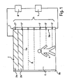
- FIG. 1 shows a securing device with a sensor strip 1 for a sectional door 2, the individual sections 2a, 2b run in guide rails 3a, 3b.
- the gate 2 moves in the direction of movement according to the arrow A.
- the range of movement of the gate 2 with the direction of movement A is described by the plane E.
- an object 4 here a person. If the movement of the door 2 continued in the direction A, a collision of the door 2 with the person 4 would take place.
- a sensor strip 1 with distance sensors 5 is mounted, wherein in FIG. 1 the guide rail 3a is just covered by the sensor bar 1.
- the sensors 5 send out beams 6 and can also receive their reflections again.
- the beams 6 extend perpendicular to the direction of movement immediately in front of the plane E.
- the beams therefore run at a small distance from the plane E.
- the beams 6 extend perpendicular to the sensor bar 1 or (in the projection of the FIG. 1 ) to the guide rail 3a.
- the distance sensors 5 are designed as TOF sensors. In the lower portion of the range of motion, the beams of the sensors 5 'impinge on the person 4. These sensors 5' each individually determine the distance between the guide rail 3a in which the respective sensors 5 'are located to the respective impact point on the person 4. Thus, it can first be determined how far the gate 2, which moves in the direction A, about as far away from the person 4, since it is known how many sensors 5 are still between the gate 2 and the person 4.
- the sensors 5 are located in the area which has already been passed through the gate 2 along the guide rail 3a, and these sensors 5" therefore detect a distance to a detected object, namely a part of the door 2 which projects into the monitoring area Therefore, as the door moves from top to bottom, more and more sensors will measure that reference value, suggesting that the detected object is not one Obstacle or a person can act, but that the gate 2 was detected.
- the evaluation of the data takes place in this embodiment in a microcontroller which is integrated in the sensor strip 1.
- This microcontroller is designed to send a switch-off signal to the controller 7 in the event of an obstacle in the monitoring area.
- the controller 7 in turn controls the motor 8 for the movement of the gate. 2
- the person 4 moves within the plane E, it can be determined by the sensors 5 ', in which direction and optionally also in which speed this moves.
Claims (11)
- Dispositif de sécurité pour la sécurisation d'un élément de mouvement mobile guidé dans un guidage contre des collisions indésirables de l'élément de mouvement avec un objet qui se trouve dans la zone de surveillance, avec un dispositif à capteur (1) pour la surveillance de l'élément de mouvement (2) en ce qui concerne les collisions indésirables de l'élément de mouvement avec l'objet (4), avec au moins deux capteurs (5) pour la détection de l'objet, les capteurs comprenant un émetteur et un récepteur pour l'émission et la réception de rayonnements électromagnétiques (6), les capteurs étant disposés les uns à côté des autres de façon à ce qu'ils puissant être posés parallèlement au guidage (3a) et les capteurs (5) étant en outre orientés de façon à ce que les rayonnements (6) qu'ils émettent traversent la zone de surveillance, les capteurs (5) étant conçus comme des capteurs de distance pour la détermination de la distance de l'objet (4) et une unité électronique étant prévue pour la lecture des données déterminées par les capteurs et pour l'envoi de commandes et/ou de signaux, caractérisé en ce que l'unité électronique est conçue pour déterminer, à partir, d'une distance déterminée par au moins un des capteurs, si l'élément de mouvement ou l'objet est détecté, en comparant la distance déterminée par les capteurs avec une valeur de référence, la valeur de référence utilisée étant la distance mesurée lorsque l'élément de mouvement se trouve dans la zone de surveillance.
- Dispositif de sécurité selon la revendication 1, caractérisé en ce que les capteurs sont disposés dans une première barre.
- Dispositif de sécurité selon l'une des revendications précédentes, caractérisé en ce qu'au moins deux des capteurs (5) sont orientés de façon à ce que leurs rayonnements soient parallèles.
- Dispositif de sécurité selon l'une des revendications précédentes, caractérisé en ce qu'au moins un des capteurs (5) est disposé de façon à ce que ses rayonnements soient émis perpendiculairement au guidage.
- Dispositif de sécurité selon l'une des revendications précédentes, caractérisé en ce qu'au moins un des capteurs (5) est conçu comme suit :- capteur à réflexion infrarouge ou- capteur time-of-flight ou- capteur 3D.
- Dispositif de sécurité selon l'une des revendications précédentes, caractérisé en ce qu'au moins un des capteurs (5) est conçu de façon à ce que ses rayonnements traversent une zone conique.
- Dispositif de sécurité selon l'une des revendications précédentes, caractérisé en ce que l'unité électronique est conçue pour déterminer, grâce au dispositif à capteur, la direction de mouvement de l'élément de mouvement et/ou de l'objet.
- Dispositif de sécurité selon l'une des revendications précédentes, caractérisé en ce qu'une unité de contrôle est prévue pour le contrôle de l'élément de mouvement, qui comprend l'unité électronique ou qui peut être connectée à l'unité électronique.
- Porte (2), plus particulièrement porte roulante, sectionnelle ou coulissante, caractérisée en ce qu'un dispositif de sécurité selon l'une des revendications précédentes est prévu.
- Procédé de contrôle du mouvement d'un élément de mouvement mobile et guidé dans un guidage, à l'aide d'un dispositif de sécurité selon l'une des revendications précédentes, caractérisé en ce que le procédé comprend les étapes suivantes :- lecture des données déterminées par les capteurs (5) et attribution des données au capteur (5) lu correspondant- comparaison des données avec au moins une valeur de référence- analyse à l'aide de la comparaison et de la position du capteur (5) correspondant.
- Procédé selon l'une des revendications précédentes, caractérisé en ce qu'une activation et/ou désactivation d'au moins un des capteurs (5) a lieu en fonction de l'analyse.
Priority Applications (6)
| Application Number | Priority Date | Filing Date | Title |
|---|---|---|---|
| EP11002739.8A EP2506034B1 (fr) | 2011-04-01 | 2011-04-01 | Dispositif de capteur, dispositif de sécurité, porte et procédé de contrôle du mouvement |
| DK11002739.8T DK2506034T3 (da) | 2011-04-01 | 2011-04-01 | Sensorindretning, sikkerhedsindretning, dør og fremgangsmåde til kontrol af bevægelsen |
| US13/433,842 US9057779B2 (en) | 2011-04-01 | 2012-03-29 | Sensor device, safety device, door and method for monitoring the movement |
| JP2012081709A JP2012247410A (ja) | 2011-04-01 | 2012-03-30 | センサー装置、安全装置、ドア、および移動監視方法 |
| CN2012100932670A CN102736086A (zh) | 2011-04-01 | 2012-03-31 | 传感器装置、安全装置、门和用于控制运动的方法 |
| HK13101296.4A HK1176122A1 (en) | 2011-04-01 | 2013-01-30 | Sensor device, safety device, door and method for controlling its movement |
Applications Claiming Priority (1)
| Application Number | Priority Date | Filing Date | Title |
|---|---|---|---|
| EP11002739.8A EP2506034B1 (fr) | 2011-04-01 | 2011-04-01 | Dispositif de capteur, dispositif de sécurité, porte et procédé de contrôle du mouvement |
Publications (2)
| Publication Number | Publication Date |
|---|---|
| EP2506034A1 EP2506034A1 (fr) | 2012-10-03 |
| EP2506034B1 true EP2506034B1 (fr) | 2013-05-29 |
Family
ID=44023054
Family Applications (1)
| Application Number | Title | Priority Date | Filing Date |
|---|---|---|---|
| EP11002739.8A Revoked EP2506034B1 (fr) | 2011-04-01 | 2011-04-01 | Dispositif de capteur, dispositif de sécurité, porte et procédé de contrôle du mouvement |
Country Status (6)
| Country | Link |
|---|---|
| US (1) | US9057779B2 (fr) |
| EP (1) | EP2506034B1 (fr) |
| JP (1) | JP2012247410A (fr) |
| CN (1) | CN102736086A (fr) |
| DK (1) | DK2506034T3 (fr) |
| HK (1) | HK1176122A1 (fr) |
Cited By (2)
| Publication number | Priority date | Publication date | Assignee | Title |
|---|---|---|---|---|
| US9057779B2 (en) | 2011-04-01 | 2015-06-16 | Cedes Ag | Sensor device, safety device, door and method for monitoring the movement |
| US11198220B2 (en) | 2017-06-28 | 2021-12-14 | Datalogic Ip Tech S.R.L. | Safety system |
Families Citing this family (23)
| Publication number | Priority date | Publication date | Assignee | Title |
|---|---|---|---|---|
| WO2014143655A1 (fr) | 2013-03-15 | 2014-09-18 | Springs Window Fashions, Llc | Agencement d'entraînement de système de levage et de commande motorisé de couvre-fenêtre |
| EP2845985B1 (fr) | 2013-07-18 | 2015-11-18 | Cedes Ag | Système de sécurisation de porte |
| DE102015101017B4 (de) * | 2015-01-23 | 2018-02-22 | Efaflex Tor- Und Sicherheitssysteme Gmbh & Co. Kg | Verfahren zur Steuerung einer Toranordnung sowie derartige Toranordnung und eine Sicherheitseinrichtung hierfür |
| CN106199738A (zh) * | 2015-02-15 | 2016-12-07 | 鲍星合 | 物体存在检测装置及方法 |
| US10619397B2 (en) * | 2015-09-14 | 2020-04-14 | Rytec Corporation | System and method for safety management in roll-up doors |
| EP3443192B1 (fr) | 2016-04-14 | 2020-11-11 | Dimon Systems AB | Appareil pour fermer verticalement une ouverture et procédé pour identifier un besoin de maintenance et/ou un problème de sécurité pour celui-ci |
| EP3519861A4 (fr) | 2016-10-03 | 2020-09-02 | Sensotech, Inc. | Système de détection basé sur le temps de vol (tof) pour une porte automatique |
| JP6978226B2 (ja) * | 2017-05-31 | 2021-12-08 | 三和シヤッター工業株式会社 | 開閉制御システム |
| US11055942B2 (en) | 2017-08-01 | 2021-07-06 | The Chamberlain Group, Inc. | System and method for facilitating access to a secured area |
| WO2019028039A1 (fr) | 2017-08-01 | 2019-02-07 | The Chamberlain Group, Inc. | Système pour faciliter l'accès à une zone sécurisée |
| CN107780750A (zh) * | 2017-10-24 | 2018-03-09 | 四川星门科技有限公司 | 用于智能门的360°扫描防夹结构 |
| CN107859449A (zh) * | 2017-10-24 | 2018-03-30 | 四川星门科技有限公司 | 适用于自动门窗的防撞感应装置 |
| CN107806303A (zh) * | 2017-10-24 | 2018-03-16 | 四川星门科技有限公司 | 具有较快响应速度的防撞传感器 |
| EP3527766B1 (fr) * | 2018-02-16 | 2023-03-29 | Cedes AG | Procédé de configurationd'un capteur de porte |
| EP3530869B1 (fr) | 2018-02-27 | 2020-04-15 | Cedes AG | Barriere lumineuse comportant des informations de distance et son utilisation |
| JP6585230B1 (ja) * | 2018-05-16 | 2019-10-02 | 東芝エレベータ株式会社 | 乗客コンベア |
| DE102018214215A1 (de) * | 2018-08-22 | 2020-02-27 | Geze Gmbh | Vorrichtung zur Überwachung von Türen, Fenstern oder dergleichen |
| EP3899186A4 (fr) | 2018-12-21 | 2022-10-05 | Rytec Corporation | Système et procédé de sécurité pour portes à enroulement par le haut |
| CA3132557C (fr) | 2019-03-08 | 2023-05-23 | The Chamberlain Group Llc | Systeme et procede de detection d'objets |
| US11851936B2 (en) | 2019-08-15 | 2023-12-26 | The Chamberlain Group Llc | System and method for movable barrier monitoring |
| JP2022546942A (ja) * | 2019-08-27 | 2022-11-10 | マランテック アントリープス ウント シュトイエルングステヒニク ゲーエムベーハー ウント コー.カーゲー | ドアシステム内のドア位置を決定するための方法 |
| CN111595455B (zh) * | 2020-05-29 | 2021-01-01 | 四川兴事发门窗有限责任公司 | 一种基于测温门的体温测量系统及方法 |
| CN113969744A (zh) * | 2021-11-03 | 2022-01-25 | 济南巨光风田门业有限公司 | 稳定性强的工业自动快速堆积门 |
Family Cites Families (26)
| Publication number | Priority date | Publication date | Assignee | Title |
|---|---|---|---|---|
| ES2165014T3 (es) * | 1997-06-30 | 2002-03-01 | Cedes Ag | Cortina de luz o barrera optica con dispositivo de alineacion. |
| DE19739543A1 (de) * | 1997-09-09 | 1999-03-11 | Efaflex Inzeniring D O O Ljubl | Sicherheitseinrichtung für motorisch angetriebene Tore |
| DE19739544A1 (de) * | 1997-09-09 | 1999-03-11 | Efaflex Inzeniring D O O Ljubl | Sicherheitseinrichtung für motorisch angetriebene Systeme |
| DE19804632C2 (de) | 1998-02-05 | 2001-10-11 | Agta Record Ag Fehraltorf | Verfahren und Vorrichtung zur Ansteuerung und/oder Überwachung eines motorisch angetriebenen Flügels |
| JPH11354831A (ja) * | 1998-06-10 | 1999-12-24 | Keyence Corp | 狭い角度特性の光軸付きエリアセンサ |
| DE29901664U1 (de) | 1999-02-03 | 1999-04-15 | Samaco Gmbh | Hubtor mit Lichtgitter-Überwachungseinrichtung |
| DE19946476A1 (de) | 1999-09-28 | 2001-03-29 | Sick Ag | Verfahren und Vorrichtung zum Überwachen eines Schutzbereichs |
| JP4639293B2 (ja) | 2001-02-27 | 2011-02-23 | オプテックス株式会社 | 自動ドアセンサ |
| JP2002250607A (ja) | 2001-02-27 | 2002-09-06 | Optex Co Ltd | 物体検知センサ |
| EP1442319B1 (fr) | 2001-11-08 | 2006-08-09 | Siemens Aktiengesellschaft | Reseau de lumiere laser destine a la mesure de distance |
| DE10203145C1 (de) * | 2002-01-28 | 2003-04-17 | Efaflex Tor & Sicherheitssys | Einrichtung zur automatischen Betätigung eines Tores, insbesondere eines Hubtores |
| JP3857605B2 (ja) | 2002-03-27 | 2006-12-13 | 株式会社ミツバ | 車両用自動開閉装置 |
| JP2003314875A (ja) * | 2002-04-18 | 2003-11-06 | Kaname Omaki | 塵埃侵入防止装置及びシートシャッター |
| JP2004279127A (ja) * | 2003-03-13 | 2004-10-07 | Omron Corp | ライトカーテン |
| CH697014A5 (de) | 2003-07-25 | 2008-03-14 | Supercomputing Systems Ag | Absicherung und/oder Ueberwachung von Systemen. |
| JP2005325537A (ja) | 2004-05-12 | 2005-11-24 | Hokuyo Automatic Co | 安全センサ |
| DE102005003794A1 (de) | 2005-01-26 | 2006-08-03 | Cedes Ag | Vorrichtung zur Absicherung eines angetriebenen Bewegungselements |
| CN101180444B (zh) | 2005-04-19 | 2013-01-16 | 塞德斯股份公司 | 用于控制驱动运动件的设备 |
| DE102007031157A1 (de) | 2006-12-15 | 2008-06-26 | Sick Ag | Optoelektronischer Sensor sowie Verfahren zur Erfassung und Abstandsbestimmung eines Objekts |
| JP5136927B2 (ja) | 2007-10-09 | 2013-02-06 | オプテックス株式会社 | レーザエリアセンサ |
| DE102007050334A1 (de) | 2007-10-18 | 2009-04-23 | Efaflex Tor- Und Sicherheitssysteme Gmbh & Co. Kg | Verfahren und Einrichtung zur Steuerung eines vertikal oder horizontal bewegten Tores unter Absicherung der Torschließebene gegenüber Hindernissen |
| JP5076070B2 (ja) | 2007-10-26 | 2012-11-21 | オプテックス株式会社 | 対象検出装置、対象検出方法、および対象検出プログラム |
| DE102008023294B4 (de) | 2008-01-16 | 2010-02-04 | Cedes Ag | Sicherungssystem zur Absicherung eines sich bewegenden, geführten Bewegungselements gegen ungewollte Kollisionen |
| JP5373486B2 (ja) * | 2009-06-12 | 2013-12-18 | 日本電産コパル株式会社 | 開閉部用の検出装置 |
| EP2506034B1 (fr) | 2011-04-01 | 2013-05-29 | Cedes AG | Dispositif de capteur, dispositif de sécurité, porte et procédé de contrôle du mouvement |
| US8988213B2 (en) * | 2011-10-28 | 2015-03-24 | Cedes Ag | Safety device, closing device and evaluation unit |
-
2011
- 2011-04-01 EP EP11002739.8A patent/EP2506034B1/fr not_active Revoked
- 2011-04-01 DK DK11002739.8T patent/DK2506034T3/da active
-
2012
- 2012-03-29 US US13/433,842 patent/US9057779B2/en active Active
- 2012-03-30 JP JP2012081709A patent/JP2012247410A/ja active Pending
- 2012-03-31 CN CN2012100932670A patent/CN102736086A/zh active Pending
-
2013
- 2013-01-30 HK HK13101296.4A patent/HK1176122A1/xx not_active IP Right Cessation
Cited By (2)
| Publication number | Priority date | Publication date | Assignee | Title |
|---|---|---|---|---|
| US9057779B2 (en) | 2011-04-01 | 2015-06-16 | Cedes Ag | Sensor device, safety device, door and method for monitoring the movement |
| US11198220B2 (en) | 2017-06-28 | 2021-12-14 | Datalogic Ip Tech S.R.L. | Safety system |
Also Published As
| Publication number | Publication date |
|---|---|
| US20120292514A1 (en) | 2012-11-22 |
| CN102736086A (zh) | 2012-10-17 |
| EP2506034A1 (fr) | 2012-10-03 |
| HK1176122A1 (en) | 2013-07-19 |
| JP2012247410A (ja) | 2012-12-13 |
| US9057779B2 (en) | 2015-06-16 |
| DK2506034T3 (da) | 2013-09-02 |
Similar Documents
| Publication | Publication Date | Title |
|---|---|---|
| EP2506034B1 (fr) | Dispositif de capteur, dispositif de sécurité, porte et procédé de contrôle du mouvement | |
| DE102008044990B4 (de) | Verfahren und Vorrichtung zur Ansteuerung und/oder Überwachung eines motorisch angetriebenen Flügels während der Öffnungsphase | |
| EP1841942B1 (fr) | Dispositif pour sécuriser un élément mobile entraîné | |
| EP2586959B2 (fr) | Dispositif de sécurisation, dispositif de fermeture et unité d'évaluation | |
| EP2574718B1 (fr) | Système de sécurité pour la sécurisation d'un élément mobile guidé, en déplacement, contre des collisions involontaires | |
| EP0902158B1 (fr) | Dispositif de sécurité pour dispositifs entraínés par moteur | |
| EP1089030B1 (fr) | Procédé et dispositif de contrôle d'une zone de protection | |
| EP1470314B1 (fr) | Porte avec actionnement automatique, notamment porte relevable, et methode pour son actionnement | |
| EP2648022B1 (fr) | Dispositif de surveillance et porte pivotante | |
| EP0232866B1 (fr) | Dispositif de commande de l'ouverture et/ou fermeture de portes à mouvement rapide | |
| DE102010026140A1 (de) | Überwachungsvorrichtung zur Absicherung eines angetriebenen Elements | |
| EP3584400B1 (fr) | Porte de protection et procédé de fonctionnement d'une porte de protection | |
| DE102006008513A1 (de) | Sensor-Überwachungseinrichtung | |
| DE102010017398B3 (de) | Verfahren zum Betrieb eines Tores sowie Vorrichtung zum Betrieb eines Tores | |
| WO2016116178A1 (fr) | Procédé de commande d'un système de porte ainsi que système de porte et dispositif de sécurité correspondant | |
| DE202018105041U1 (de) | Torsicherheitssystem zum Verhindern von Kollisionen zwischen einem Fahrzeug und einem Tor und ein Computerprogramm | |
| EP2799384A1 (fr) | Porte motorisée dotée d'un dispositif de sécurité | |
| DE102007001178A1 (de) | Berührungsloser Einklemmschutz | |
| EP2195795B1 (fr) | Dispositif pour commander un élément mobile motorisé, en particulier une porte ou un portail | |
| EP3556700A1 (fr) | Installation d'ascenseur dotée d'un dispositif de mesure de position ainsi que procédé de détermination d'une position d'une cabine d'ascenseur dans une cage d'ascenseur | |
| DE202013002006U1 (de) | Kontrolleinrichtung | |
| WO2007115756A2 (fr) | Dispositif pour influencer le déplacement d'éléments de meuble l'un vers l'autre et meuble | |
| EP4265875A1 (fr) | Procédé de commande d'une installation de porte | |
| DE102013013779A1 (de) | Gebäudeabschlussvorrichtung und Verfahren für den Betrieb einer derartigen Gebäudeabschlussvorrichtung | |
| EP2853677A1 (fr) | Procédé et dispositif de sécurisation de portail |
Legal Events
| Date | Code | Title | Description |
|---|---|---|---|
| PUAI | Public reference made under article 153(3) epc to a published international application that has entered the european phase |
Free format text: ORIGINAL CODE: 0009012 |
|
| 17P | Request for examination filed |
Effective date: 20110401 |
|
| AK | Designated contracting states |
Kind code of ref document: A1 Designated state(s): AL AT BE BG CH CY CZ DE DK EE ES FI FR GB GR HR HU IE IS IT LI LT LU LV MC MK MT NL NO PL PT RO RS SE SI SK SM TR |
|
| AX | Request for extension of the european patent |
Extension state: BA ME |
|
| GRAP | Despatch of communication of intention to grant a patent |
Free format text: ORIGINAL CODE: EPIDOSNIGR1 |
|
| GRAS | Grant fee paid |
Free format text: ORIGINAL CODE: EPIDOSNIGR3 |
|
| GRAA | (expected) grant |
Free format text: ORIGINAL CODE: 0009210 |
|
| AK | Designated contracting states |
Kind code of ref document: B1 Designated state(s): AL AT BE BG CH CY CZ DE DK EE ES FI FR GB GR HR HU IE IS IT LI LT LU LV MC MK MT NL NO PL PT RO RS SE SI SK SM TR |
|
| REG | Reference to a national code |
Ref country code: GB Ref legal event code: FG4D Free format text: NOT ENGLISH |
|
| REG | Reference to a national code |
Ref country code: CH Ref legal event code: EP |
|
| REG | Reference to a national code |
Ref country code: AT Ref legal event code: REF Ref document number: 614739 Country of ref document: AT Kind code of ref document: T Effective date: 20130615 |
|
| REG | Reference to a national code |
Ref country code: IE Ref legal event code: FG4D Free format text: LANGUAGE OF EP DOCUMENT: GERMAN |
|
| REG | Reference to a national code |
Ref country code: HK Ref legal event code: DE Ref document number: 1176122 Country of ref document: HK |
|
| REG | Reference to a national code |
Ref country code: DE Ref legal event code: R096 Ref document number: 502011000780 Country of ref document: DE Effective date: 20130725 |
|
| REG | Reference to a national code |
Ref country code: DK Ref legal event code: T3 |
|
| REG | Reference to a national code |
Ref country code: SE Ref legal event code: TRGR |
|
| REG | Reference to a national code |
Ref country code: CH Ref legal event code: NV Representative=s name: KELLER AND PARTNER PATENTANWAELTE AG, CH |
|
| REG | Reference to a national code |
Ref country code: LT Ref legal event code: MG4D |
|
| PG25 | Lapsed in a contracting state [announced via postgrant information from national office to epo] |
Ref country code: PT Free format text: LAPSE BECAUSE OF FAILURE TO SUBMIT A TRANSLATION OF THE DESCRIPTION OR TO PAY THE FEE WITHIN THE PRESCRIBED TIME-LIMIT Effective date: 20130930 Ref country code: FI Free format text: LAPSE BECAUSE OF FAILURE TO SUBMIT A TRANSLATION OF THE DESCRIPTION OR TO PAY THE FEE WITHIN THE PRESCRIBED TIME-LIMIT Effective date: 20130529 Ref country code: ES Free format text: LAPSE BECAUSE OF FAILURE TO SUBMIT A TRANSLATION OF THE DESCRIPTION OR TO PAY THE FEE WITHIN THE PRESCRIBED TIME-LIMIT Effective date: 20130909 Ref country code: GR Free format text: LAPSE BECAUSE OF FAILURE TO SUBMIT A TRANSLATION OF THE DESCRIPTION OR TO PAY THE FEE WITHIN THE PRESCRIBED TIME-LIMIT Effective date: 20130830 Ref country code: IS Free format text: LAPSE BECAUSE OF FAILURE TO SUBMIT A TRANSLATION OF THE DESCRIPTION OR TO PAY THE FEE WITHIN THE PRESCRIBED TIME-LIMIT Effective date: 20130929 Ref country code: SI Free format text: LAPSE BECAUSE OF FAILURE TO SUBMIT A TRANSLATION OF THE DESCRIPTION OR TO PAY THE FEE WITHIN THE PRESCRIBED TIME-LIMIT Effective date: 20130529 Ref country code: LT Free format text: LAPSE BECAUSE OF FAILURE TO SUBMIT A TRANSLATION OF THE DESCRIPTION OR TO PAY THE FEE WITHIN THE PRESCRIBED TIME-LIMIT Effective date: 20130529 Ref country code: NO Free format text: LAPSE BECAUSE OF FAILURE TO SUBMIT A TRANSLATION OF THE DESCRIPTION OR TO PAY THE FEE WITHIN THE PRESCRIBED TIME-LIMIT Effective date: 20130829 |
|
| REG | Reference to a national code |
Ref country code: NL Ref legal event code: VDEP Effective date: 20130529 |
|
| REG | Reference to a national code |
Ref country code: HK Ref legal event code: GR Ref document number: 1176122 Country of ref document: HK |
|
| PG25 | Lapsed in a contracting state [announced via postgrant information from national office to epo] |
Ref country code: HR Free format text: LAPSE BECAUSE OF FAILURE TO SUBMIT A TRANSLATION OF THE DESCRIPTION OR TO PAY THE FEE WITHIN THE PRESCRIBED TIME-LIMIT Effective date: 20130529 Ref country code: PL Free format text: LAPSE BECAUSE OF FAILURE TO SUBMIT A TRANSLATION OF THE DESCRIPTION OR TO PAY THE FEE WITHIN THE PRESCRIBED TIME-LIMIT Effective date: 20130529 Ref country code: RS Free format text: LAPSE BECAUSE OF FAILURE TO SUBMIT A TRANSLATION OF THE DESCRIPTION OR TO PAY THE FEE WITHIN THE PRESCRIBED TIME-LIMIT Effective date: 20130529 Ref country code: BG Free format text: LAPSE BECAUSE OF FAILURE TO SUBMIT A TRANSLATION OF THE DESCRIPTION OR TO PAY THE FEE WITHIN THE PRESCRIBED TIME-LIMIT Effective date: 20130829 |
|
| PG25 | Lapsed in a contracting state [announced via postgrant information from national office to epo] |
Ref country code: LV Free format text: LAPSE BECAUSE OF FAILURE TO SUBMIT A TRANSLATION OF THE DESCRIPTION OR TO PAY THE FEE WITHIN THE PRESCRIBED TIME-LIMIT Effective date: 20130529 |
|
| PG25 | Lapsed in a contracting state [announced via postgrant information from national office to epo] |
Ref country code: CZ Free format text: LAPSE BECAUSE OF FAILURE TO SUBMIT A TRANSLATION OF THE DESCRIPTION OR TO PAY THE FEE WITHIN THE PRESCRIBED TIME-LIMIT Effective date: 20130529 Ref country code: SK Free format text: LAPSE BECAUSE OF FAILURE TO SUBMIT A TRANSLATION OF THE DESCRIPTION OR TO PAY THE FEE WITHIN THE PRESCRIBED TIME-LIMIT Effective date: 20130529 Ref country code: EE Free format text: LAPSE BECAUSE OF FAILURE TO SUBMIT A TRANSLATION OF THE DESCRIPTION OR TO PAY THE FEE WITHIN THE PRESCRIBED TIME-LIMIT Effective date: 20130529 |
|
| PG25 | Lapsed in a contracting state [announced via postgrant information from national office to epo] |
Ref country code: RO Free format text: LAPSE BECAUSE OF FAILURE TO SUBMIT A TRANSLATION OF THE DESCRIPTION OR TO PAY THE FEE WITHIN THE PRESCRIBED TIME-LIMIT Effective date: 20130529 Ref country code: IT Free format text: LAPSE BECAUSE OF FAILURE TO SUBMIT A TRANSLATION OF THE DESCRIPTION OR TO PAY THE FEE WITHIN THE PRESCRIBED TIME-LIMIT Effective date: 20130529 Ref country code: NL Free format text: LAPSE BECAUSE OF FAILURE TO SUBMIT A TRANSLATION OF THE DESCRIPTION OR TO PAY THE FEE WITHIN THE PRESCRIBED TIME-LIMIT Effective date: 20130529 |
|
| PLBI | Opposition filed |
Free format text: ORIGINAL CODE: 0009260 |
|
| PLAX | Notice of opposition and request to file observation + time limit sent |
Free format text: ORIGINAL CODE: EPIDOSNOBS2 |
|
| 26 | Opposition filed |
Opponent name: SICK AG Effective date: 20140228 Opponent name: BIRCHER REGLOMAT AG Effective date: 20140228 Opponent name: PEPPERL & FUCHS GMBH Effective date: 20140228 |
|
| REG | Reference to a national code |
Ref country code: DE Ref legal event code: R026 Ref document number: 502011000780 Country of ref document: DE Effective date: 20140228 |
|
| PLAB | Opposition data, opponent's data or that of the opponent's representative modified |
Free format text: ORIGINAL CODE: 0009299OPPO |
|
| R26 | Opposition filed (corrected) |
Opponent name: PEPPERL + FUCHS GMBH Effective date: 20140228 |
|
| PLBB | Reply of patent proprietor to notice(s) of opposition received |
Free format text: ORIGINAL CODE: EPIDOSNOBS3 |
|
| PG25 | Lapsed in a contracting state [announced via postgrant information from national office to epo] |
Ref country code: MC Free format text: LAPSE BECAUSE OF FAILURE TO SUBMIT A TRANSLATION OF THE DESCRIPTION OR TO PAY THE FEE WITHIN THE PRESCRIBED TIME-LIMIT Effective date: 20130529 Ref country code: LU Free format text: LAPSE BECAUSE OF FAILURE TO SUBMIT A TRANSLATION OF THE DESCRIPTION OR TO PAY THE FEE WITHIN THE PRESCRIBED TIME-LIMIT Effective date: 20140401 |
|
| REG | Reference to a national code |
Ref country code: FR Ref legal event code: ST Effective date: 20141231 |
|
| REG | Reference to a national code |
Ref country code: IE Ref legal event code: MM4A |
|
| PG25 | Lapsed in a contracting state [announced via postgrant information from national office to epo] |
Ref country code: FR Free format text: LAPSE BECAUSE OF NON-PAYMENT OF DUE FEES Effective date: 20140430 |
|
| REG | Reference to a national code |
Ref country code: CH Ref legal event code: PCAR Free format text: NEW ADDRESS: EIGERSTRASSE 2 POSTFACH, 3000 BERN 14 (CH) |
|
| PG25 | Lapsed in a contracting state [announced via postgrant information from national office to epo] |
Ref country code: IE Free format text: LAPSE BECAUSE OF NON-PAYMENT OF DUE FEES Effective date: 20140401 |
|
| GBPC | Gb: european patent ceased through non-payment of renewal fee |
Effective date: 20150401 |
|
| PG25 | Lapsed in a contracting state [announced via postgrant information from national office to epo] |
Ref country code: GB Free format text: LAPSE BECAUSE OF NON-PAYMENT OF DUE FEES Effective date: 20150401 |
|
| PG25 | Lapsed in a contracting state [announced via postgrant information from national office to epo] |
Ref country code: MT Free format text: LAPSE BECAUSE OF FAILURE TO SUBMIT A TRANSLATION OF THE DESCRIPTION OR TO PAY THE FEE WITHIN THE PRESCRIBED TIME-LIMIT Effective date: 20130529 |
|
| REG | Reference to a national code |
Ref country code: DE Ref legal event code: R064 Ref document number: 502011000780 Country of ref document: DE Ref country code: DE Ref legal event code: R103 Ref document number: 502011000780 Country of ref document: DE |
|
| PG25 | Lapsed in a contracting state [announced via postgrant information from national office to epo] |
Ref country code: SM Free format text: LAPSE BECAUSE OF FAILURE TO SUBMIT A TRANSLATION OF THE DESCRIPTION OR TO PAY THE FEE WITHIN THE PRESCRIBED TIME-LIMIT Effective date: 20130529 |
|
| RDAF | Communication despatched that patent is revoked |
Free format text: ORIGINAL CODE: EPIDOSNREV1 |
|
| PG25 | Lapsed in a contracting state [announced via postgrant information from national office to epo] |
Ref country code: CY Free format text: LAPSE BECAUSE OF FAILURE TO SUBMIT A TRANSLATION OF THE DESCRIPTION OR TO PAY THE FEE WITHIN THE PRESCRIBED TIME-LIMIT Effective date: 20130529 |
|
| PG25 | Lapsed in a contracting state [announced via postgrant information from national office to epo] |
Ref country code: TR Free format text: LAPSE BECAUSE OF FAILURE TO SUBMIT A TRANSLATION OF THE DESCRIPTION OR TO PAY THE FEE WITHIN THE PRESCRIBED TIME-LIMIT Effective date: 20130529 Ref country code: HU Free format text: LAPSE BECAUSE OF FAILURE TO SUBMIT A TRANSLATION OF THE DESCRIPTION OR TO PAY THE FEE WITHIN THE PRESCRIBED TIME-LIMIT; INVALID AB INITIO Effective date: 20110401 |
|
| PGFP | Annual fee paid to national office [announced via postgrant information from national office to epo] |
Ref country code: DE Payment date: 20160516 Year of fee payment: 6 Ref country code: CH Payment date: 20160420 Year of fee payment: 6 |
|
| PGFP | Annual fee paid to national office [announced via postgrant information from national office to epo] |
Ref country code: SE Payment date: 20160420 Year of fee payment: 6 Ref country code: BE Payment date: 20160420 Year of fee payment: 6 Ref country code: DK Payment date: 20160420 Year of fee payment: 6 |
|
| RDAG | Patent revoked |
Free format text: ORIGINAL CODE: 0009271 |
|
| STAA | Information on the status of an ep patent application or granted ep patent |
Free format text: STATUS: PATENT REVOKED |
|
| REG | Reference to a national code |
Ref country code: CH Ref legal event code: PLX |
|
| 27W | Patent revoked |
Effective date: 20160427 |
|
| PG25 | Lapsed in a contracting state [announced via postgrant information from national office to epo] |
Ref country code: LI Free format text: LAPSE BECAUSE OF THE APPLICANT RENOUNCES Effective date: 20130529 Ref country code: CH Free format text: LAPSE BECAUSE OF THE APPLICANT RENOUNCES Effective date: 20130529 |
|
| REG | Reference to a national code |
Ref country code: AT Ref legal event code: MA03 Ref document number: 614739 Country of ref document: AT Kind code of ref document: T Effective date: 20160427 |
|
| REG | Reference to a national code |
Ref country code: SE Ref legal event code: ECNC |
|
| PG25 | Lapsed in a contracting state [announced via postgrant information from national office to epo] |
Ref country code: AL Free format text: LAPSE BECAUSE OF FAILURE TO SUBMIT A TRANSLATION OF THE DESCRIPTION OR TO PAY THE FEE WITHIN THE PRESCRIBED TIME-LIMIT Effective date: 20130529 |
|
| P01 | Opt-out of the competence of the unified patent court (upc) registered |
Effective date: 20230519 |