EP2845985B1 - Système de sécurisation de porte - Google Patents
Système de sécurisation de porte Download PDFInfo
- Publication number
- EP2845985B1 EP2845985B1 EP13003615.5A EP13003615A EP2845985B1 EP 2845985 B1 EP2845985 B1 EP 2845985B1 EP 13003615 A EP13003615 A EP 13003615A EP 2845985 B1 EP2845985 B1 EP 2845985B1
- Authority
- EP
- European Patent Office
- Prior art keywords
- gate
- signal
- designed
- safety system
- edge
- Prior art date
- Legal status (The legal status is an assumption and is not a legal conclusion. Google has not performed a legal analysis and makes no representation as to the accuracy of the status listed.)
- Active
Links
- 230000004888 barrier function Effects 0.000 claims description 34
- 238000011156 evaluation Methods 0.000 claims description 15
- 230000001419 dependent effect Effects 0.000 claims description 10
- 238000001514 detection method Methods 0.000 claims description 10
- 238000012795 verification Methods 0.000 claims description 6
- 230000009849 deactivation Effects 0.000 claims description 4
- 238000012544 monitoring process Methods 0.000 claims 3
- 230000001012 protector Effects 0.000 claims 2
- 230000005540 biological transmission Effects 0.000 claims 1
- 230000008901 benefit Effects 0.000 description 5
- 230000006870 function Effects 0.000 description 3
- 238000005096 rolling process Methods 0.000 description 3
- 229910000831 Steel Inorganic materials 0.000 description 2
- 239000010959 steel Substances 0.000 description 2
- 101150087426 Gnal gene Proteins 0.000 description 1
- 230000009471 action Effects 0.000 description 1
- 230000015572 biosynthetic process Effects 0.000 description 1
- 239000010408 film Substances 0.000 description 1
- 238000000034 method Methods 0.000 description 1
- 230000035945 sensitivity Effects 0.000 description 1
- 239000010409 thin film Substances 0.000 description 1
Images

Classifications
-
- E—FIXED CONSTRUCTIONS
- E06—DOORS, WINDOWS, SHUTTERS, OR ROLLER BLINDS IN GENERAL; LADDERS
- E06B—FIXED OR MOVABLE CLOSURES FOR OPENINGS IN BUILDINGS, VEHICLES, FENCES OR LIKE ENCLOSURES IN GENERAL, e.g. DOORS, WINDOWS, BLINDS, GATES
- E06B9/00—Screening or protective devices for wall or similar openings, with or without operating or securing mechanisms; Closures of similar construction
- E06B9/56—Operating, guiding or securing devices or arrangements for roll-type closures; Spring drums; Tape drums; Counterweighting arrangements therefor
- E06B9/80—Safety measures against dropping or unauthorised opening; Braking or immobilising devices; Devices for limiting unrolling
- E06B9/82—Safety measures against dropping or unauthorised opening; Braking or immobilising devices; Devices for limiting unrolling automatic
- E06B9/88—Safety measures against dropping or unauthorised opening; Braking or immobilising devices; Devices for limiting unrolling automatic for limiting unrolling
-
- E—FIXED CONSTRUCTIONS
- E05—LOCKS; KEYS; WINDOW OR DOOR FITTINGS; SAFES
- E05F—DEVICES FOR MOVING WINGS INTO OPEN OR CLOSED POSITION; CHECKS FOR WINGS; WING FITTINGS NOT OTHERWISE PROVIDED FOR, CONCERNED WITH THE FUNCTIONING OF THE WING
- E05F15/00—Power-operated mechanisms for wings
- E05F15/40—Safety devices, e.g. detection of obstructions or end positions
- E05F15/42—Detection using safety edges
- E05F15/43—Detection using safety edges responsive to disruption of energy beams, e.g. light or sound
- E05F2015/434—Detection using safety edges responsive to disruption of energy beams, e.g. light or sound with cameras or optical sensors
- E05F2015/435—Detection using safety edges responsive to disruption of energy beams, e.g. light or sound with cameras or optical sensors by interruption of the beam
- E05F2015/436—Detection using safety edges responsive to disruption of energy beams, e.g. light or sound with cameras or optical sensors by interruption of the beam the beam being parallel to the wing edge
-
- E—FIXED CONSTRUCTIONS
- E05—LOCKS; KEYS; WINDOW OR DOOR FITTINGS; SAFES
- E05Y—INDEXING SCHEME ASSOCIATED WITH SUBCLASSES E05D AND E05F, RELATING TO CONSTRUCTION ELEMENTS, ELECTRIC CONTROL, POWER SUPPLY, POWER SIGNAL OR TRANSMISSION, USER INTERFACES, MOUNTING OR COUPLING, DETAILS, ACCESSORIES, AUXILIARY OPERATIONS NOT OTHERWISE PROVIDED FOR, APPLICATION THEREOF
- E05Y2900/00—Application of doors, windows, wings or fittings thereof
- E05Y2900/10—Application of doors, windows, wings or fittings thereof for buildings or parts thereof
- E05Y2900/106—Application of doors, windows, wings or fittings thereof for buildings or parts thereof for garages
-
- E—FIXED CONSTRUCTIONS
- E06—DOORS, WINDOWS, SHUTTERS, OR ROLLER BLINDS IN GENERAL; LADDERS
- E06B—FIXED OR MOVABLE CLOSURES FOR OPENINGS IN BUILDINGS, VEHICLES, FENCES OR LIKE ENCLOSURES IN GENERAL, e.g. DOORS, WINDOWS, BLINDS, GATES
- E06B9/00—Screening or protective devices for wall or similar openings, with or without operating or securing mechanisms; Closures of similar construction
- E06B9/56—Operating, guiding or securing devices or arrangements for roll-type closures; Spring drums; Tape drums; Counterweighting arrangements therefor
- E06B9/68—Operating devices or mechanisms, e.g. with electric drive
- E06B2009/6809—Control
- E06B2009/6818—Control using sensors
- E06B2009/6827—Control using sensors sensing light
-
- E—FIXED CONSTRUCTIONS
- E06—DOORS, WINDOWS, SHUTTERS, OR ROLLER BLINDS IN GENERAL; LADDERS
- E06B—FIXED OR MOVABLE CLOSURES FOR OPENINGS IN BUILDINGS, VEHICLES, FENCES OR LIKE ENCLOSURES IN GENERAL, e.g. DOORS, WINDOWS, BLINDS, GATES
- E06B9/00—Screening or protective devices for wall or similar openings, with or without operating or securing mechanisms; Closures of similar construction
- E06B9/56—Operating, guiding or securing devices or arrangements for roll-type closures; Spring drums; Tape drums; Counterweighting arrangements therefor
- E06B9/68—Operating devices or mechanisms, e.g. with electric drive
- E06B2009/6809—Control
- E06B2009/6872—Control using counters to determine shutter position
Definitions
- the invention relates to a Torêtssystem with a light grid arrangement for the detection of objects in the plane of movement of the gate and the gate edge wherein the security system between gate and object.
- Tornells of the type mentioned are known from the prior art. These usually form a grid of light barriers within the plane of movement of the door and transversely to the direction of movement of the leading gate edge.
- the photoelectric barriers are formed by a transmitter strip and a receiver strip which are provided opposite each other for mounting on or in the guide of the gate edge, so that the gate interrupts the photoelectric barriers successively when closing.
- the known Torommessysteme offer a method with which a distinction can be made between the detection of an object or the gate edge.
- the 2011 filed patent application EP 2 586 959 A1 CEDES AG describes a Torzzissystem in which the pattern detected by the receiver bar is statically compared with predefined patterns in order to be able to immediately distinguish between object and gate edge even after a failure and restart of the Torinerungssystems.
- the 2011 filed patent application EP 2 506 034 A1 CEDES AG describes a Torellesssystem, in which the light grid is formed of distance sensors and is distinguished on the basis of the detected distance between the object and the door edge.
- a disadvantage is the aforementioned Torommessystemen with the exception of CEDES EP 2 229 496 B1 and the CEDES EP 2 506 034 A1 in that the tamper-evident system can be manipulated by inserting a narrow object, such as a rod or an arm, below the gate edge in the path of the gate in such a way that it interrupts only the photocell closest to the gate edge.
- a narrow object such as a rod or an arm
- the torching system usually recognizes this as a door edge and not as an object. As a result, the object can be damaged and squeezed in particular by the completely closing gate on the ground.
- the inventive gate securing system serves to protect a gate with a gate edge slidably leading in a plane of movement and in a movement direction against collision with an object and comprises a light grid direction with at least 2 transmitting elements and at least 2 Receiving elements for the formation of light barrier beams in the plane of motion for detecting an object in the plane of movement and the gate edge and further comprises an evaluation device which is adapted to distinguish due to the detection of the light grid device between the object or gate edge and to generate a security signal upon detection of an object and further comprises a position sensor device which is formed separately from the light grid device for detecting a position of the gate and for outputting a position signal which corresponds to a position range of the gate edge, wherein the evaluation device is further adapted to generate a check signal due to the interruption of a particular light barrier beam of the light grid device and wherein there is further provided a control device which is designed to carry out a plausibility check as a function of the position signal and the checking signal gnal and generate a safety signal depending on the plaus
- the Torzzissystem can have the advantage that when an incorrect distinction of the evaluation that incorrectly assigns the gate edge instead of an object as a cause and therefore incorrectly generates no security signal in an incorrect detection of the light grid device, the Torommessystem still responds safely because now instead of the evaluation, the control device can generate the safety signal.
- the safety of the door safety system can be increased.
- the position signal may preferably be a value from a range of values.
- the check signal may preferably be associated with the position of a light grid steel.
- the evaluation device can preferably generate an associated characteristic checking signal, which is assigned to the respective positions of the light grating bars, in each case for a plurality of light grid beams when interrupted
- the evaluation device is adapted to generate due to the interruption of a particular light barrier beam of the light grid device, a verification signal which is associated with the particular Licht-enstrahl characteristically and a position range of the gate edge on the line of the particular Licht-enstrahls or between the particular Licht 2enstrahl and the closed position of the door corresponds and Furthermore, the control device is designed to transmit the safety signal generate when the position signal corresponding position range is outside the position corresponding to the check signal position range
- the particular light barrier should be interrupted by the gate edge or, if the gate body also breaks the light barrier beams in the plane of movement, by the subsequent gate leaves. Then, the position signal should reflect a position of the gate edge at the particular light barrier beam or between the particular light barrier and the closed position of the door. If this is not the case, then there is an unsafe condition of the gate, so that a safety signal is ore eugt.
- the door bodies In sectional doors, the door bodies usually have sectional sections of a certain depth, which usually interrupt the light barrier beams. In the case of film doors, the door body usually has a thin film which usually does not interrupt the light barrier beams.
- the position sensor device preferably comprises a rotary encoder and / or one or more end-zone switches.
- the efficiency of the Torschssystems can be increased.
- Rotary encoders can be mounted on the drive shaft of the gate and determine the position of the gate edge by means of the unwinding rotation of the gate.
- End-of-range switches can act as a cam or curve on the gate edge or the gate body on a switch on the door guide and thus determine the position or a position range of the gate edge.
- the Torellesssystem further comprises a control device in particular for position-dependent control of the speed of movement of the door and / or in particular for the position-dependent deactivation of a hose edge safety at the gate edge.
- the position sensor device is designed to pass signals to at least one further control device, in particular for position-dependent control of the speed of movement of the door and / or in particular for the position-dependent deactivation of a hose edge safety device at the gate edge.
- the position-dependent speed control may allow about a deceleration before the closing position.
- the Torommessystem can have the advantage that it increases the comfort for the user.
- the evaluation device is connected to the light grid device by a common carrier, in particular by a common housing.
- the control device is connected to the drive control of the door or also connected to the light grid device by a common carrier, in particular by a common housing.
- a common carrier or housing can facilitate assembly and increase ruggedness.
- the Torellesssystem can facilitate the assembly and / or increase the robustness against wear.
- the light grid arrangement is formed so that the particular light barrier beam is disposed at a height between 2 cm and 30 cm, in particular between 5 cm and 20 cm, in particular between 10 cm and 15 cm above the ground.
- a low location of the particular beam of light beam can reduce the risk of crushing.
- the lowest light beam beam is not selected so that a slowing down of the gate is still possible.
- the Torellesssystem can reduce the risk of crushing.
- the position sensor device is designed such that the output of the position signal takes place when detecting the gate about +/- 20 cm, in particular about +/- 10 cm, in particular about +/- 5 cm, in particular about +/- 1 cm, in particular exactly at the position of the gate when the gate edge enters the specific light barrier.
- the position sensor device is preferably designed so that the output of the position signal takes place during a certain period of time after which the door has reached a specific position.
- the range tolerant output of the position signal may increase the stability of the plausibility check.
- the Torschssystem can increase the system stability.
- the position sensor device is configured to record the position of the gate associated with a position signal by a learning run of the gate, wherein in particular the one or more check signals are used to detect and / or store the position of the gate,
- the gate can close approximately from top to bottom and when passing and interrupting the or the particular light beam beams, the or the corresponding verification signals are passed to the control device that connects them in their memory with the or simultaneously incoming position signals.
- the position signals can represent values from a value range that corresponds to the travel path of the gate.
- the Torellesssystem and / or the evaluation device and / or the control device is adapted to stop the gate when the safety signal generated and / or reverse.
- the inventive gate comprises a Torschssystem invention of the aforementioned type.
- the inventive gate can have the advantages of Torschssystems.
- Fig. 1 shows a gate 1 with a Torellesssystem 2 with a End Schlschalter 3 on which a cam curve 4 acts.
- the cam operates the end range switch when the gate edge 5 is in an area between the particular light barrier beam 6 and the ground.
- a light grid device 7 consists of a transmitter strip 8 with transmitters 9 and a receiver strip 10 with receivers 11 assigned in parallel.
- the light barrier beams 12 are interrupted by the gate, the specific light barrier beam 6 is interrupted by an object and the light barrier beam 13 is not interrupted.
- the receivers are connected by a connection 14 to the evaluation device 15, which is located in the housing 16 of the light grid device 7.
- the evaluation device is connected to the motor controller 17 via a connection 18 via which a security signal can be sent.
- the receiver 19 of the specific light barrier beam 6 is connected to the control device 21 via a connection 20.
- the end range switch 3 is connected to the control device 21 via a connection 22.
- the control device 21 is connected to the motor controller 17 and can also transmit this to a safety signal.
- the motor controller 17 is connected to the motor 23 which drives the door 1 by rolling or rolling over the shaft 24. The motor control stops and reverses the rolling motor in case of a safety signal.
- the object 25 interrupts the determined light beam beam 6. This leads to the detection by the associated receiver 19 and to the generation of a specific light beam beam associated with the verification signal which is transmitted via the connection 20 to the control device.
- the End Schlsschalter 3 is not yet switched by the cam curve 4 of the gate. This circuit state of a position of the gate edge 5 even before the specific light barrier beam 6 and is transmitted as a position signal to the control device 21.
- the control device has the position corresponding to the check signal and the position range corresponding to the position signal stored in the memory. The control device now compares the check signal with the position signal for plausibility as to whether the position range corresponding to the check signal lies within the position range of the position signal.
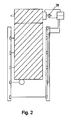
- Fig. 2 shows the gate 1 with a Torellesssystem 2 with a rotary encoder 26 which is connected to the control device 21.
- the rotary encoder detects the rotation of the shaft 24 and transmits the rotation to the control device.
- the control unit calculates the position of the gate and the gate edge from the rotational values. The position corresponding to the gate edge on the particular beam steel 6 is entered or taught the control device.
- the other structure and mode of action correspond FIG. 1 ,
Landscapes
- Engineering & Computer Science (AREA)
- Structural Engineering (AREA)
- Architecture (AREA)
- Civil Engineering (AREA)
- Power-Operated Mechanisms For Wings (AREA)
Claims (10)
- Système de sécurisation de portail- destiné à sécuriser un portail contre une collision avec un objet, le portail comprenant un rebord de portail antérieur mobile dans un plan de mouvement et dans une direction de mouvement, comportant- un dispositif à grille lumineuse- pourvu d'au moins 2 éléments émetteurs et d'au moins 2 éléments récepteurs- destiné à la formation de faisceaux d'une barrière lumineuse dans le plan de mouvement- destiné à la détection d'un objet dans le plan de mouvement et au niveau du rebord de portail ;- un dispositif d'évaluation conçu pour,- sur la base de la détection du dispositif à grille lumineuse,- faire la distinction entre un objet et le rebord du portail- et, lorsqu'un objet est détecté, pour produire un signal de sécurité ;- un dispositif de capteurs de positioncaractérisé en ce que- qui est conçu séparément du dispositif à grille lumineuse- pour détecter une position du portail et- pour délivrer un signal de position- qui correspond à une zone de position du rebord du portail,- le dispositif d'évaluation est conçu en outre- pour produire un signal de vérification sur la base de l'interruption d'un certain faisceau de barrière lumineuse du dispositif à grille lumineuse et- un dispositif de contrôle est présent et conçu pour- mettre en oeuvre un contrôle de plausibilité en fonction du signal de position et du signal de vérification- et pour produire un signal de sécurité en fonction du contrôle de plausibilité.
- Système de sécurisation de portail selon la revendication 1, caractérisé en ce que- le dispositif d'évaluation est conçu- pour produire un signal de vérification sur la base de l'interruption d'un certain faisceau de barrière lumineuse du dispositif à grille lumineuse, lequel signal de vérification est associé de manière caractéristique au certain faisceau de barrière lumineuse et correspond à une zone de position du rebord du portail sur la ligne du certain faisceau de barrière lumineuse ou entre le certain faisceau de barrière lumineuse et la position fermée du portail, et/ou en ce que- le dispositif de contrôle est conçu- pour produire le signal de sécurité- lorsque la zone de position correspondant au signal de position se situe à l'extérieur de la zone de position correspondant au signal de vérification.
- Système de sécurisation de portail selon l'une des revendications précédentes,
caractérisé en ce que- le dispositif de capteur de position- comprend un résolveur et/ou- un ou plusieurs commutateurs de zone d'extrémité. - Système de sécurisation de portail selon l'une des revendications précédentes,
caractérisé en ce que- le système de sécurisation de portail comprend un autre dispositif de commande- en particulier pour commander la vitesse de déplacement du portail en fonction de la position, et/ou- en particulier pour désactiver une sécurisation de rebord tubulaire placée sur le rebord du portail, en fonction de la position, et/ou- le dispositif de capteur de position est conçu- pour transmettre des signaux à au moins un autre dispositif de commande- en particulier pour commander la vitesse de déplacement du portail, en fonction de la position, et/ou- en particulier pour désactiver une sécurisation de rebord tubulaire sur le rebord du portail, en fonction de la position. - Système de sécurisation de portail selon l'une quelconque des revendications précédentes
caractérisé en ce que- le dispositif d'évaluation- est relié au dispositif à grille lumineuse par un support commun, et est en particulier entouré par un boîtier commun, et/ou- le dispositif de contrôle- est relié à la commande d'entraînement du portail par un support commun, et est en particulier entouré par un boîtier commun ou- est également relié au dispositif à grille lumineuse par un support commun, et est en particulier entouré par un boîtier commun. - Système de sécurisation de portail selon l'une des revendications précédentes,
caractérisé en ce que- le dispositif à grille lumineuse est conçu de sorte que- le certain faisceau de barrière lumineuse est disposé à une hauteur comprise entre 2 cm et 30 cm au-dessus du sol, en particulier entre 5 cm et 20 cm, en particulier entre 10 cm et 15 cm. - Système de sécurisation de portail selon l'une des revendications précédentes,
caractérisé en ce que- le dispositif de capteur de position est conçu de sorte que- le signal de position est émis lorsque le portail est détectée à environ ± 20 cm de la position du portail lorsque le rebord du portail pénètre dans la certaine barrière lumineuse, en particulier à environ ± 10 cm, en particulier à environ ± 5 cm, en particulier à environ ± 1 cm, en particulier précisément dans la position du portail lorsque le rebord du portail pénètre dans la certaine barrière lumineuse, et/ou en ce que- le signal de position est émis pendant une certaine durée après que le portail a atteint une certaine position. - Système de sécurisation de portail selon l'une des revendications précédentes,
caractérisé en ce que- le dispositif de capteur de position est conçu- pour enregistrer la position du portail associée à un signal de position à l'aide d'une course d'apprentissage du portail,- en particulier le signal ou les signaux de vérification étant utilisés pour détecter et/ou mettre en mémoire la position du portail. - Système de sécurisation de portail selon l'une quelconque des revendications précédentes,
caractérisé en ce que- le système de sécurisation de portail et/ou le dispositif d'évaluation et/ou le dispositif de contrôle sont conçus- pour arrêter le portail et/ou pour renverser la marche de celui-ci lorsque le signal de sécurité est produit. - Portail comprenant un système de sécurisation de portail selon l'une des revendications précédentes
Priority Applications (2)
| Application Number | Priority Date | Filing Date | Title |
|---|---|---|---|
| DK13003615.5T DK2845985T3 (en) | 2013-07-18 | 2013-07-18 | Port Security System |
| EP13003615.5A EP2845985B1 (fr) | 2013-07-18 | 2013-07-18 | Système de sécurisation de porte |
Applications Claiming Priority (1)
| Application Number | Priority Date | Filing Date | Title |
|---|---|---|---|
| EP13003615.5A EP2845985B1 (fr) | 2013-07-18 | 2013-07-18 | Système de sécurisation de porte |
Publications (2)
| Publication Number | Publication Date |
|---|---|
| EP2845985A1 EP2845985A1 (fr) | 2015-03-11 |
| EP2845985B1 true EP2845985B1 (fr) | 2015-11-18 |
Family
ID=48875463
Family Applications (1)
| Application Number | Title | Priority Date | Filing Date |
|---|---|---|---|
| EP13003615.5A Active EP2845985B1 (fr) | 2013-07-18 | 2013-07-18 | Système de sécurisation de porte |
Country Status (2)
| Country | Link |
|---|---|
| EP (1) | EP2845985B1 (fr) |
| DK (1) | DK2845985T3 (fr) |
Families Citing this family (2)
| Publication number | Priority date | Publication date | Assignee | Title |
|---|---|---|---|---|
| EP3530869B1 (fr) * | 2018-02-27 | 2020-04-15 | Cedes AG | Barriere lumineuse comportant des informations de distance et son utilisation |
| FR3101911B1 (fr) * | 2019-10-09 | 2021-10-01 | Sofineco Soc Pour Letude Et Le Financement Dentreprises Industrielles Et Commerciales | Barre palpeuse virtuelle pour porte de manutention |
Family Cites Families (6)
| Publication number | Priority date | Publication date | Assignee | Title |
|---|---|---|---|---|
| DE19739543A1 (de) | 1997-09-09 | 1999-03-11 | Efaflex Inzeniring D O O Ljubl | Sicherheitseinrichtung für motorisch angetriebene Tore |
| DE102005003794A1 (de) | 2005-01-26 | 2006-08-03 | Cedes Ag | Vorrichtung zur Absicherung eines angetriebenen Bewegungselements |
| DE102008023294B4 (de) | 2008-01-16 | 2010-02-04 | Cedes Ag | Sicherungssystem zur Absicherung eines sich bewegenden, geführten Bewegungselements gegen ungewollte Kollisionen |
| DE102010017398B3 (de) * | 2010-06-16 | 2011-12-01 | Feig Electronic Gmbh | Verfahren zum Betrieb eines Tores sowie Vorrichtung zum Betrieb eines Tores |
| EP2506034B1 (fr) | 2011-04-01 | 2013-05-29 | Cedes AG | Dispositif de capteur, dispositif de sécurité, porte et procédé de contrôle du mouvement |
| DK2586959T4 (en) | 2011-10-28 | 2017-01-09 | Cedes Ag | Safety device, closure and evaluation unit |
-
2013
- 2013-07-18 DK DK13003615.5T patent/DK2845985T3/en active
- 2013-07-18 EP EP13003615.5A patent/EP2845985B1/fr active Active
Also Published As
| Publication number | Publication date |
|---|---|
| EP2845985A1 (fr) | 2015-03-11 |
| DK2845985T3 (en) | 2016-02-29 |
Similar Documents
| Publication | Publication Date | Title |
|---|---|---|
| EP2586959B2 (fr) | Dispositif de sécurisation, dispositif de fermeture et unité d'évaluation | |
| EP2506034B1 (fr) | Dispositif de capteur, dispositif de sécurité, porte et procédé de contrôle du mouvement | |
| DE3618692C2 (fr) | ||
| EP1089030B1 (fr) | Procédé et dispositif de contrôle d'une zone de protection | |
| EP1841942B1 (fr) | Dispositif pour sécuriser un élément mobile entraîné | |
| EP2574718B1 (fr) | Système de sécurité pour la sécurisation d'un élément mobile guidé, en déplacement, contre des collisions involontaires | |
| DE4201971A1 (de) | Verdunkelungsvorrichtung | |
| EP2404859B1 (fr) | Dispositif de surveillance pour sécuriser un élément entraîné | |
| DE19739544A1 (de) | Sicherheitseinrichtung für motorisch angetriebene Systeme | |
| DE102008044990A1 (de) | Verfahren und Vorrichtung zur Ansteuerung und/oder Überwachung eines motorisch angetriebenen Flügels während der Öffnungsphase | |
| DE102006008513A1 (de) | Sensor-Überwachungseinrichtung | |
| EP3247860A1 (fr) | Procédé de commande d'un système de porte ainsi que système de porte et dispositif de sécurité correspondant | |
| DE102007033766A1 (de) | Lichtgitter | |
| DE10228930B4 (de) | Sensorvorrichtung für eine automatische Drehtüranlage | |
| EP2306063A2 (fr) | Capteur de sécurité | |
| DE102014111694A1 (de) | Vorrichtung zur Überwachung einer Maschinenbewegung und Verfahren zum Überwachen einer Maschinenbewegung | |
| EP3584400A1 (fr) | Porte de protection et procédé de fonctionnement d'une porte de protection | |
| EP2845985B1 (fr) | Système de sécurisation de porte | |
| EP2799384A1 (fr) | Porte motorisée dotée d'un dispositif de sécurité | |
| EP3660251A1 (fr) | Dispositif de protection, en particulier portail industriel | |
| DE202006002000U1 (de) | Tor mit Lichtschrankenanordnung | |
| DE102013212518A1 (de) | Automatische Fenster- oder Türanlage | |
| DE102008018628B4 (de) | Automatische Türanlage | |
| DE60201287T2 (de) | Motorisierter Rolladen mit Vorrichtung zum Abschalten eines Motorantriebes bei Erkennung eines Hindernisses | |
| EP2634358B1 (fr) | Détection d'obstacles intelligente |
Legal Events
| Date | Code | Title | Description |
|---|---|---|---|
| 17P | Request for examination filed |
Effective date: 20130808 |
|
| AK | Designated contracting states |
Kind code of ref document: A1 Designated state(s): AL AT BE BG CH CY CZ DE DK EE ES FI FR GB GR HR HU IE IS IT LI LT LU LV MC MK MT NL NO PL PT RO RS SE SI SK SM TR |
|
| AX | Request for extension of the european patent |
Extension state: BA ME |
|
| PUAI | Public reference made under article 153(3) epc to a published international application that has entered the european phase |
Free format text: ORIGINAL CODE: 0009012 |
|
| RBV | Designated contracting states (corrected) |
Designated state(s): AL AT BE BG CH CY CZ DE DK EE ES FI FR GB GR HR HU IE IS IT LI LT LU LV MC MK MT NL NO PL PT RO RS SE SI SK SM TR |
|
| GRAP | Despatch of communication of intention to grant a patent |
Free format text: ORIGINAL CODE: EPIDOSNIGR1 |
|
| RIC1 | Information provided on ipc code assigned before grant |
Ipc: E06B 9/88 20060101ALI20150608BHEP Ipc: E06B 9/68 20060101AFI20150608BHEP |
|
| RAP1 | Party data changed (applicant data changed or rights of an application transferred) |
Owner name: CEDES AG Owner name: FRABA AG |
|
| INTG | Intention to grant announced |
Effective date: 20150715 |
|
| GRAS | Grant fee paid |
Free format text: ORIGINAL CODE: EPIDOSNIGR3 |
|
| GRAA | (expected) grant |
Free format text: ORIGINAL CODE: 0009210 |
|
| AK | Designated contracting states |
Kind code of ref document: B1 Designated state(s): AL AT BE BG CH CY CZ DE DK EE ES FI FR GB GR HR HU IE IS IT LI LT LU LV MC MK MT NL NO PL PT RO RS SE SI SK SM TR |
|
| REG | Reference to a national code |
Ref country code: GB Ref legal event code: FG4D Free format text: NOT ENGLISH |
|
| REG | Reference to a national code |
Ref country code: CH Ref legal event code: EP |
|
| REG | Reference to a national code |
Ref country code: AT Ref legal event code: REF Ref document number: 761680 Country of ref document: AT Kind code of ref document: T Effective date: 20151215 |
|
| REG | Reference to a national code |
Ref country code: IE Ref legal event code: FG4D Free format text: LANGUAGE OF EP DOCUMENT: GERMAN |
|
| REG | Reference to a national code |
Ref country code: DE Ref legal event code: R096 Ref document number: 502013001467 Country of ref document: DE |
|
| REG | Reference to a national code |
Ref country code: DK Ref legal event code: T3 Effective date: 20160222 |
|
| REG | Reference to a national code |
Ref country code: NL Ref legal event code: MP Effective date: 20160218 |
|
| REG | Reference to a national code |
Ref country code: LT Ref legal event code: MG4D |
|
| PG25 | Lapsed in a contracting state [announced via postgrant information from national office to epo] |
Ref country code: IS Free format text: LAPSE BECAUSE OF FAILURE TO SUBMIT A TRANSLATION OF THE DESCRIPTION OR TO PAY THE FEE WITHIN THE PRESCRIBED TIME-LIMIT Effective date: 20160318 Ref country code: ES Free format text: LAPSE BECAUSE OF FAILURE TO SUBMIT A TRANSLATION OF THE DESCRIPTION OR TO PAY THE FEE WITHIN THE PRESCRIBED TIME-LIMIT Effective date: 20151118 Ref country code: IT Free format text: LAPSE BECAUSE OF FAILURE TO SUBMIT A TRANSLATION OF THE DESCRIPTION OR TO PAY THE FEE WITHIN THE PRESCRIBED TIME-LIMIT Effective date: 20151118 Ref country code: NL Free format text: LAPSE BECAUSE OF FAILURE TO SUBMIT A TRANSLATION OF THE DESCRIPTION OR TO PAY THE FEE WITHIN THE PRESCRIBED TIME-LIMIT Effective date: 20151118 Ref country code: NO Free format text: LAPSE BECAUSE OF FAILURE TO SUBMIT A TRANSLATION OF THE DESCRIPTION OR TO PAY THE FEE WITHIN THE PRESCRIBED TIME-LIMIT Effective date: 20160218 Ref country code: HR Free format text: LAPSE BECAUSE OF FAILURE TO SUBMIT A TRANSLATION OF THE DESCRIPTION OR TO PAY THE FEE WITHIN THE PRESCRIBED TIME-LIMIT Effective date: 20151118 Ref country code: LT Free format text: LAPSE BECAUSE OF FAILURE TO SUBMIT A TRANSLATION OF THE DESCRIPTION OR TO PAY THE FEE WITHIN THE PRESCRIBED TIME-LIMIT Effective date: 20151118 |
|
| PG25 | Lapsed in a contracting state [announced via postgrant information from national office to epo] |
Ref country code: PL Free format text: LAPSE BECAUSE OF FAILURE TO SUBMIT A TRANSLATION OF THE DESCRIPTION OR TO PAY THE FEE WITHIN THE PRESCRIBED TIME-LIMIT Effective date: 20151118 Ref country code: FI Free format text: LAPSE BECAUSE OF FAILURE TO SUBMIT A TRANSLATION OF THE DESCRIPTION OR TO PAY THE FEE WITHIN THE PRESCRIBED TIME-LIMIT Effective date: 20151118 Ref country code: PT Free format text: LAPSE BECAUSE OF FAILURE TO SUBMIT A TRANSLATION OF THE DESCRIPTION OR TO PAY THE FEE WITHIN THE PRESCRIBED TIME-LIMIT Effective date: 20160318 Ref country code: SE Free format text: LAPSE BECAUSE OF FAILURE TO SUBMIT A TRANSLATION OF THE DESCRIPTION OR TO PAY THE FEE WITHIN THE PRESCRIBED TIME-LIMIT Effective date: 20151118 Ref country code: RS Free format text: LAPSE BECAUSE OF FAILURE TO SUBMIT A TRANSLATION OF THE DESCRIPTION OR TO PAY THE FEE WITHIN THE PRESCRIBED TIME-LIMIT Effective date: 20151118 Ref country code: LV Free format text: LAPSE BECAUSE OF FAILURE TO SUBMIT A TRANSLATION OF THE DESCRIPTION OR TO PAY THE FEE WITHIN THE PRESCRIBED TIME-LIMIT Effective date: 20151118 Ref country code: GR Free format text: LAPSE BECAUSE OF FAILURE TO SUBMIT A TRANSLATION OF THE DESCRIPTION OR TO PAY THE FEE WITHIN THE PRESCRIBED TIME-LIMIT Effective date: 20160219 |
|
| REG | Reference to a national code |
Ref country code: CH Ref legal event code: NV Representative=s name: KELLER AND PARTNER PATENTANWAELTE AG, CH |
|
| PG25 | Lapsed in a contracting state [announced via postgrant information from national office to epo] |
Ref country code: CZ Free format text: LAPSE BECAUSE OF FAILURE TO SUBMIT A TRANSLATION OF THE DESCRIPTION OR TO PAY THE FEE WITHIN THE PRESCRIBED TIME-LIMIT Effective date: 20151118 |
|
| REG | Reference to a national code |
Ref country code: DE Ref legal event code: R097 Ref document number: 502013001467 Country of ref document: DE |
|
| PG25 | Lapsed in a contracting state [announced via postgrant information from national office to epo] |
Ref country code: SM Free format text: LAPSE BECAUSE OF FAILURE TO SUBMIT A TRANSLATION OF THE DESCRIPTION OR TO PAY THE FEE WITHIN THE PRESCRIBED TIME-LIMIT Effective date: 20151118 Ref country code: SK Free format text: LAPSE BECAUSE OF FAILURE TO SUBMIT A TRANSLATION OF THE DESCRIPTION OR TO PAY THE FEE WITHIN THE PRESCRIBED TIME-LIMIT Effective date: 20151118 Ref country code: RO Free format text: LAPSE BECAUSE OF FAILURE TO SUBMIT A TRANSLATION OF THE DESCRIPTION OR TO PAY THE FEE WITHIN THE PRESCRIBED TIME-LIMIT Effective date: 20151118 Ref country code: EE Free format text: LAPSE BECAUSE OF FAILURE TO SUBMIT A TRANSLATION OF THE DESCRIPTION OR TO PAY THE FEE WITHIN THE PRESCRIBED TIME-LIMIT Effective date: 20151118 |
|
| PLBE | No opposition filed within time limit |
Free format text: ORIGINAL CODE: 0009261 |
|
| STAA | Information on the status of an ep patent application or granted ep patent |
Free format text: STATUS: NO OPPOSITION FILED WITHIN TIME LIMIT |
|
| 26N | No opposition filed |
Effective date: 20160819 |
|
| PG25 | Lapsed in a contracting state [announced via postgrant information from national office to epo] |
Ref country code: SI Free format text: LAPSE BECAUSE OF FAILURE TO SUBMIT A TRANSLATION OF THE DESCRIPTION OR TO PAY THE FEE WITHIN THE PRESCRIBED TIME-LIMIT Effective date: 20151118 |
|
| PG25 | Lapsed in a contracting state [announced via postgrant information from national office to epo] |
Ref country code: BE Free format text: LAPSE BECAUSE OF NON-PAYMENT OF DUE FEES Effective date: 20160731 |
|
| PG25 | Lapsed in a contracting state [announced via postgrant information from national office to epo] |
Ref country code: MC Free format text: LAPSE BECAUSE OF FAILURE TO SUBMIT A TRANSLATION OF THE DESCRIPTION OR TO PAY THE FEE WITHIN THE PRESCRIBED TIME-LIMIT Effective date: 20151118 |
|
| PG25 | Lapsed in a contracting state [announced via postgrant information from national office to epo] |
Ref country code: FR Free format text: LAPSE BECAUSE OF NON-PAYMENT OF DUE FEES Effective date: 20160801 |
|
| REG | Reference to a national code |
Ref country code: FR Ref legal event code: ST Effective date: 20170331 |
|
| REG | Reference to a national code |
Ref country code: IE Ref legal event code: MM4A |
|
| PG25 | Lapsed in a contracting state [announced via postgrant information from national office to epo] |
Ref country code: IE Free format text: LAPSE BECAUSE OF NON-PAYMENT OF DUE FEES Effective date: 20160718 |
|
| PG25 | Lapsed in a contracting state [announced via postgrant information from national office to epo] |
Ref country code: LU Free format text: LAPSE BECAUSE OF NON-PAYMENT OF DUE FEES Effective date: 20160718 |
|
| GBPC | Gb: european patent ceased through non-payment of renewal fee |
Effective date: 20170718 |
|
| PG25 | Lapsed in a contracting state [announced via postgrant information from national office to epo] |
Ref country code: GB Free format text: LAPSE BECAUSE OF NON-PAYMENT OF DUE FEES Effective date: 20170718 |
|
| PG25 | Lapsed in a contracting state [announced via postgrant information from national office to epo] |
Ref country code: HU Free format text: LAPSE BECAUSE OF FAILURE TO SUBMIT A TRANSLATION OF THE DESCRIPTION OR TO PAY THE FEE WITHIN THE PRESCRIBED TIME-LIMIT; INVALID AB INITIO Effective date: 20130718 |
|
| PG25 | Lapsed in a contracting state [announced via postgrant information from national office to epo] |
Ref country code: MT Free format text: LAPSE BECAUSE OF FAILURE TO SUBMIT A TRANSLATION OF THE DESCRIPTION OR TO PAY THE FEE WITHIN THE PRESCRIBED TIME-LIMIT Effective date: 20151118 Ref country code: MK Free format text: LAPSE BECAUSE OF FAILURE TO SUBMIT A TRANSLATION OF THE DESCRIPTION OR TO PAY THE FEE WITHIN THE PRESCRIBED TIME-LIMIT Effective date: 20151118 Ref country code: CY Free format text: LAPSE BECAUSE OF FAILURE TO SUBMIT A TRANSLATION OF THE DESCRIPTION OR TO PAY THE FEE WITHIN THE PRESCRIBED TIME-LIMIT Effective date: 20151118 |
|
| PG25 | Lapsed in a contracting state [announced via postgrant information from national office to epo] |
Ref country code: BG Free format text: LAPSE BECAUSE OF FAILURE TO SUBMIT A TRANSLATION OF THE DESCRIPTION OR TO PAY THE FEE WITHIN THE PRESCRIBED TIME-LIMIT Effective date: 20151118 |
|
| PG25 | Lapsed in a contracting state [announced via postgrant information from national office to epo] |
Ref country code: TR Free format text: LAPSE BECAUSE OF FAILURE TO SUBMIT A TRANSLATION OF THE DESCRIPTION OR TO PAY THE FEE WITHIN THE PRESCRIBED TIME-LIMIT Effective date: 20151118 Ref country code: AL Free format text: LAPSE BECAUSE OF FAILURE TO SUBMIT A TRANSLATION OF THE DESCRIPTION OR TO PAY THE FEE WITHIN THE PRESCRIBED TIME-LIMIT Effective date: 20151118 |
|
| REG | Reference to a national code |
Ref country code: AT Ref legal event code: MM01 Ref document number: 761680 Country of ref document: AT Kind code of ref document: T Effective date: 20180718 |
|
| PG25 | Lapsed in a contracting state [announced via postgrant information from national office to epo] |
Ref country code: AT Free format text: LAPSE BECAUSE OF NON-PAYMENT OF DUE FEES Effective date: 20180718 |
|
| REG | Reference to a national code |
Ref country code: CH Ref legal event code: PFA Owner name: CEDES AG, DE Free format text: FORMER OWNER: CEDES AG, DE |
|
| P01 | Opt-out of the competence of the unified patent court (upc) registered |
Effective date: 20230519 |
|
| PGFP | Annual fee paid to national office [announced via postgrant information from national office to epo] |
Ref country code: CH Payment date: 20230801 Year of fee payment: 11 |
|
| PGFP | Annual fee paid to national office [announced via postgrant information from national office to epo] |
Ref country code: DK Payment date: 20230724 Year of fee payment: 11 Ref country code: DE Payment date: 20230720 Year of fee payment: 11 |