EP2586959B2 - Dispositif de sécurisation, dispositif de fermeture et unité d'évaluation - Google Patents
Dispositif de sécurisation, dispositif de fermeture et unité d'évaluation Download PDFInfo
- Publication number
- EP2586959B2 EP2586959B2 EP11008656.8A EP11008656A EP2586959B2 EP 2586959 B2 EP2586959 B2 EP 2586959B2 EP 11008656 A EP11008656 A EP 11008656A EP 2586959 B2 EP2586959 B2 EP 2586959B2
- Authority
- EP
- European Patent Office
- Prior art keywords
- movement
- sensors
- evaluation unit
- safety device
- movement element
- Prior art date
- Legal status (The legal status is an assumption and is not a legal conclusion. Google has not performed a legal analysis and makes no representation as to the accuracy of the status listed.)
- Active
Links
- 238000011156 evaluation Methods 0.000 title claims description 54
- 230000033001 locomotion Effects 0.000 claims description 134
- 239000013598 vector Substances 0.000 claims description 55
- 230000004888 barrier function Effects 0.000 claims description 51
- 238000001514 detection method Methods 0.000 claims description 11
- 238000013507 mapping Methods 0.000 claims description 10
- 230000006870 function Effects 0.000 description 7
- 230000015654 memory Effects 0.000 description 5
- 238000011161 development Methods 0.000 description 3
- 238000013461 design Methods 0.000 description 2
- 230000000694 effects Effects 0.000 description 2
- 238000003780 insertion Methods 0.000 description 2
- 230000037431 insertion Effects 0.000 description 2
- 238000007620 mathematical function Methods 0.000 description 2
- 230000003287 optical effect Effects 0.000 description 2
- 230000000149 penetrating effect Effects 0.000 description 2
- 230000015556 catabolic process Effects 0.000 description 1
- 230000000052 comparative effect Effects 0.000 description 1
- 230000001419 dependent effect Effects 0.000 description 1
- 239000011888 foil Substances 0.000 description 1
- 238000005259 measurement Methods 0.000 description 1
- 238000000034 method Methods 0.000 description 1
- 238000012806 monitoring device Methods 0.000 description 1
- 238000012545 processing Methods 0.000 description 1
- 230000001105 regulatory effect Effects 0.000 description 1
- 238000009420 retrofitting Methods 0.000 description 1
- 230000003068 static effect Effects 0.000 description 1
Images


Classifications
-
- E—FIXED CONSTRUCTIONS
- E06—DOORS, WINDOWS, SHUTTERS, OR ROLLER BLINDS IN GENERAL; LADDERS
- E06B—FIXED OR MOVABLE CLOSURES FOR OPENINGS IN BUILDINGS, VEHICLES, FENCES OR LIKE ENCLOSURES IN GENERAL, e.g. DOORS, WINDOWS, BLINDS, GATES
- E06B9/00—Screening or protective devices for wall or similar openings, with or without operating or securing mechanisms; Closures of similar construction
- E06B9/56—Operating, guiding or securing devices or arrangements for roll-type closures; Spring drums; Tape drums; Counterweighting arrangements therefor
- E06B9/80—Safety measures against dropping or unauthorised opening; Braking or immobilising devices; Devices for limiting unrolling
- E06B9/82—Safety measures against dropping or unauthorised opening; Braking or immobilising devices; Devices for limiting unrolling automatic
- E06B9/88—Safety measures against dropping or unauthorised opening; Braking or immobilising devices; Devices for limiting unrolling automatic for limiting unrolling
-
- E—FIXED CONSTRUCTIONS
- E05—LOCKS; KEYS; WINDOW OR DOOR FITTINGS; SAFES
- E05F—DEVICES FOR MOVING WINGS INTO OPEN OR CLOSED POSITION; CHECKS FOR WINGS; WING FITTINGS NOT OTHERWISE PROVIDED FOR, CONCERNED WITH THE FUNCTIONING OF THE WING
- E05F15/00—Power-operated mechanisms for wings
- E05F15/40—Safety devices, e.g. detection of obstructions or end positions
- E05F15/42—Detection using safety edges
- E05F15/43—Detection using safety edges responsive to disruption of energy beams, e.g. light or sound
- E05F2015/434—Detection using safety edges responsive to disruption of energy beams, e.g. light or sound with cameras or optical sensors
- E05F2015/435—Detection using safety edges responsive to disruption of energy beams, e.g. light or sound with cameras or optical sensors by interruption of the beam
- E05F2015/436—Detection using safety edges responsive to disruption of energy beams, e.g. light or sound with cameras or optical sensors by interruption of the beam the beam being parallel to the wing edge
-
- E—FIXED CONSTRUCTIONS
- E05—LOCKS; KEYS; WINDOW OR DOOR FITTINGS; SAFES
- E05Y—INDEXING SCHEME ASSOCIATED WITH SUBCLASSES E05D AND E05F, RELATING TO CONSTRUCTION ELEMENTS, ELECTRIC CONTROL, POWER SUPPLY, POWER SIGNAL OR TRANSMISSION, USER INTERFACES, MOUNTING OR COUPLING, DETAILS, ACCESSORIES, AUXILIARY OPERATIONS NOT OTHERWISE PROVIDED FOR, APPLICATION THEREOF
- E05Y2900/00—Application of doors, windows, wings or fittings thereof
- E05Y2900/10—Application of doors, windows, wings or fittings thereof for buildings or parts thereof
- E05Y2900/106—Application of doors, windows, wings or fittings thereof for buildings or parts thereof for garages
-
- E—FIXED CONSTRUCTIONS
- E06—DOORS, WINDOWS, SHUTTERS, OR ROLLER BLINDS IN GENERAL; LADDERS
- E06B—FIXED OR MOVABLE CLOSURES FOR OPENINGS IN BUILDINGS, VEHICLES, FENCES OR LIKE ENCLOSURES IN GENERAL, e.g. DOORS, WINDOWS, BLINDS, GATES
- E06B9/00—Screening or protective devices for wall or similar openings, with or without operating or securing mechanisms; Closures of similar construction
- E06B9/56—Operating, guiding or securing devices or arrangements for roll-type closures; Spring drums; Tape drums; Counterweighting arrangements therefor
- E06B9/68—Operating devices or mechanisms, e.g. with electric drive
- E06B2009/6809—Control
- E06B2009/6818—Control using sensors
- E06B2009/6827—Control using sensors sensing light
-
- E—FIXED CONSTRUCTIONS
- E06—DOORS, WINDOWS, SHUTTERS, OR ROLLER BLINDS IN GENERAL; LADDERS
- E06B—FIXED OR MOVABLE CLOSURES FOR OPENINGS IN BUILDINGS, VEHICLES, FENCES OR LIKE ENCLOSURES IN GENERAL, e.g. DOORS, WINDOWS, BLINDS, GATES
- E06B9/00—Screening or protective devices for wall or similar openings, with or without operating or securing mechanisms; Closures of similar construction
- E06B9/56—Operating, guiding or securing devices or arrangements for roll-type closures; Spring drums; Tape drums; Counterweighting arrangements therefor
- E06B9/68—Operating devices or mechanisms, e.g. with electric drive
- E06B2009/6809—Control
- E06B2009/6818—Control using sensors
- E06B2009/6836—Control using sensors sensing obstacle
Definitions
- the invention relates to a securing device for securing a movable, guided movement element against unwanted collisions according to the preamble of claim 1 and a locking device according to the preamble of claim 12 and an evaluation unit according to the preamble of claim 13.
- the object of the invention is to propose a safety device or a locking device, which allows in an improved manner to detect a risk of collision during movement of the moving element.
- the securing device according to the invention for securing a movable, guided movement element against unwanted collisions with an object lying on a movement path of the movement element comprises at least two sensors. for detecting the object or the movement element and for outputting signals as a function of the detection. Furthermore, the security device according to the invention comprises an evaluation unit for evaluating signals from the sensors and for generating a shutdown signal based on the evaluation.
- Goals or doors, foil doors, swing gates, roller doors, telescope doors or the like come into consideration as a movement element. If necessary, parts of a closing device that are moved during the movement of the moving element may also belong to the moving element.
- the securing device serves to avoid unwanted collisions during the movement of the moving element. If the movement element, such as a gate, closed, it may happen, for example, that a person, an object or any other object enters the range of motion of the movement element. In principle, in such a case, without any securing device, the object could be caught by the moving element. Such accidents should be avoided.
- the evaluation unit of the safety device detects signals from the sensors and evaluates them, e.g. by an appropriate electronics. This detection can be carried out in the simplest way, that the evaluation unit is connected to the respective outputs of the sensors or wired.
- the sensors basically serve to detect an object, that is to say an object or a person, which enters the movement space of the movement element.
- the movement space is the space which is either passed directly by the movement element during the movement of the movement element, or an area which lies in the immediate vicinity of this zone passed by the movement element and thus to a certain extent constitutes a danger zone. An object which is thus located in this danger area may possibly cause a collision with the movement element, for example because of its spatial extent.
- this movement space or at least part of this movement space is monitored by the securing device or the sensors, so that the risk of a collision can be reduced or even eliminated altogether.
- the sensors are also arranged or designed so that the Bewegunselement can be detected.
- the sensors may, for example, be mounted in the guide rail, in which the corresponding movement element is guided and moved. It is also conceivable that the light barriers are arranged laterally offset from the guide rail, e.g. arranged parallel to the guide rail.
- the movement element is designed or arranged such that it is detected by the sensors during its guided movement, for example by the movement element penetrating into the detection area of the sensor. Among other things, this z. B. be used to determine the position of the moving element or a portion of thefroselemenzes by the sensors.
- the sensors are further configured to output signals that, among other things, carry at least the information as to whether the sensor detects an object, a person or the like or not.
- the signal can accordingly carry the information as to whether the light barrier is interrupted or not.
- the corresponding signals are transferred to the evaluation unit or of these detected.
- the securing device according to the invention offers a particularly advantageous measure, characterized in that, as soon as the sensor detects something, it can be distinguished whether it is an object and if there is a risk of collision or if it is the moving element itself, which in its movement from the sensor was recorded.
- the invention makes use of the insight that the distinction of moving element and object which could cause a collision can be found by the stationary analysis of the signal state even without considering a time course.
- those signal images which correspond to the detection of an object can be defined in advance. The determination as to whether an object is detected is then made by comparison with the defined signal images.
- the security device is characterized in that the evaluation unit is designed to detect from the at least two sensors a currently detected state vector from a set of state vectors, which unambiguously comprise all possible combinations of the signals of the sensors, and in the case of predetermined state vectors, the shutdown signal to generate.
- a state vector in the sense of the invention comprises individual information or information contents of the signals of the sensors.
- the state vector is designed such that this information or information contents can be assigned to the individual sensors.
- the information or information contents may in particular include the information as to whether the sensor detects something (an object / a person or the movement element) or not.
- the entirety of the signals of all outputs of the sensors can be viewed.
- the information consists of a digital signal, i. 0 or 1; is e.g. A voltage at the output of the sensor is detected by the sensor and vice versa.
- the state vector can be designed in various ways. It is conceivable on the one hand that a memory unit, e.g. a register bank, is provided, wherein each register a corresponding sensor can be assigned. It is also conceivable that only electrical lines are available, each of which can be assigned to a sensor.
- the information both about the detection of the sensor and about which sensor it is, can also be encoded in some other way, for example by a numerical code, by assigning different numerical values to certain sensors with specific states. On the assignment, which sensor has supplied which signal or which information, it is then also known where the sensor is arranged or which position it has.
- the evaluation unit detects the state vector, i.
- the outputs of the sensors are connected to the evaluation unit.
- the set of all possible state vectors thus unambiguously includes all possible combinations of the signals of the sensors. In particular, it can be clearly identified or deduced from the state vector which sensor detects something or not.
- the state vectors can be repeated, for example, periodically, but in principle also continuously detected.
- the currently detected state vector is the state vector that is used to determine whether or not there is a danger of collision right now or in some current time span.
- the safety device comprises sensors which can detect both the movement element and an object.
- the evaluation unit only evaluates the information from the state vector whether an object has been detected by a sensor or not and which sensor it is in each case.
- Each individual piece of information of a single sensor in itself contains only the information as to whether something is detected by the respective sensor or not.
- This single information does not yet permit the conclusion as to whether the detected object is the moving element or an object that could cause a collision. But this conclusion can be drawn from the totality of this information of all signals.
- the movement element for example, during its movement successively cover one sensor after another and thus be detected by these sensors each. During the movement of the movement element, therefore, a characteristic "pattern" is generated which sensors detect something and which are not.
- the evaluation unit If the signals of the sensors deviate from these possible patterns, an object has regularly entered the movement space and there is a danger of collision; then the evaluation unit generates a shutdown signal. Accordingly, all state vectors are known in principle, which mean that either nothing is detected or the motion element is detected or an object with the risk of collision is detected. Consequently, the shutdown signal is generated at the corresponding predetermined state vectors.
- the signals of the sensors can be evaluated, for example, by a logic circuit or by a multiplexer, in particular if digital values are available as signals.
- the decision as to whether a shutdown signal is generated can be made by either addressing certain fixed output lines of the logic circuit or of the multiplexer.
- the predetermined state vectors are ready for comparison.
- the state vectors are also present as numerical values, which are temporarily stored in a register, wherein in a further memory, the predetermined state vectors are stored and then a comparison is made.
- a digital comparison by logical switching elements are also mapped to Physical channels.
- the securing device according to the invention is advantageously used not only in the dynamic case, ie during the movement of the moving element, but also in the static case, when, for example, the gate is turned on again, the gate fully extended., Completely retracted or in an intermediate state can be located.
- the security device is in particular hardly prone to errors and allows a particularly high level of security, since the actual sensor status is always checked in detail. In addition, sensors do not have to be activated or deactivated.
- the securing device according to the invention also has the advantage that virtually no structural changes have to be made to a corresponding closing device on a gate, etc., e.g. in the sense of attaching special reflection flags. It therefore allows a particularly good retrofitting.
- a detected state vector may also be stored at least temporarily to be used for later comparison with the current state vector. It is conceivable caching in a register, other use of flip-flop circuits or the like. This measure is also advantageous if, for example, there is a state vector during the movement of the movement element and therefore it is known which state vector should be present next. By this measure, therefore, the safety and reliability of the device can be increased again. If necessary, for example, in the case of a gate in which a so-called "blowout" is possible (for example in the case of the film gate), a distinction can be made even more reliably between a blowout case and a danger of collision by an object.
- the time during the movement of the moving element can be recorded by a timer. Based on this information, e.g. to be closed, which state vector should be present. It is also conceivable, on the basis of this time, to select individual predetermined state vectors which can be used for a comparison or for the decision as to whether the shutdown signal is generated.
- safety can be increased, for example in the case of a telescopic door, since in such a door gate elements can swing out after a certain time and can no longer be detected by the sensors. In principle, this case can also be used for a blowout detection, since in the case of a "blowout", the movement element partially comes out of the guide and, e.g. at this point is no longer detected.
- the evaluation unit is designed to unambiguously assign exactly one state information from a predetermined target quantity via a bijective map to each state vector from a set of state vectors which comprise the signals of the respective sensors individually as a function of their position, and in the case of predetermined state information to signal the switch-off signal to generate.
- the evaluation unit uniquely assigns exactly one state information to each state vector.
- the state information may be, for example, a specific signal. It can be e.g. to act as an electrical or optical signal.
- the state information can also consist of a numerical value.
- the target set consists of all possible or possible state information that can be assigned to the state vectors. Any state information is an element of the target set.
- the target set does not include elements that can not be assigned to a state vector. Accordingly, the set of state vectors can again have as many elements as there are conceivable states of the sensors.
- a fuse device comprises n photoelectric sensors (n: natural number, n> 0), each output as signals 0 or 1 (not interrupted or interrupted), the set of all possible state vectors comprises 2 n (2 high n) elements. Then, the target amount also includes 2 n (2 high n) elements.
- This illustration is bijective, meaning that it is both injective and surjective.
- Injectivity means that no value of the target set is assigned to several elements of the set of state vectors.
- Surjectivity means that each value of the target quantity is also assigned to an element of the set of state vectors.
- the evaluation unit comprises a multiplexer which has a plurality of inputs and, depending on which inputs are addressed or signals are received, responds to different outputs or outputs signals via different outputs.
- the associated inputs of the multiplexer together then correspond to the state vector.
- the evaluation unit is designed to assign the sensors in each case a numerical value as a function of their position and of their signal and to assemble the state vector from these numerical values.
- a microcontroller or a processor can be used as an evaluation unit.
- the corresponding mathematical operation can be carried out by a simple programming of the microcontroller or processor.
- the signals are used to perform a mathematical operation that results in a single numerical value or result value.
- the mathematical operation represents a bijective mapping.
- Each element of the definition set is assigned an element of the target set by the mathematical operation, ie the mapping. All numerical values thus obtained, which are assigned to state vectors by the bijective mapping, together form the target quantity.
- the result value effectively represents a coding, which sensor detects something and which does not, it can also be deduced from this information whether the object or the motion element is detected. If only the movement element was detected, it can be continued during movement of the movement element, since in principle no danger of collision is to be feared. However, if exclusively or additionally an object is detected, then in fact this risk of collision is to be feared and the movement of the movement element is to be stopped.
- an addition may be provided in an embodiment of the invention.
- Such a mathematical function is usually provided by most commercially available processors / microcontrollers.
- processors / microcontrollers In addition, such a microcontroller or processor enables rapid signal processing.
- the predetermined state information is stored as comparison numbers in a comparison table stored in a memory unit such as a register bank on an EEPROM. Subsequently, the numerical values / result values are compared with the comparative figures. If the result values are one of the comparison values, then e.g. a regular case, otherwise a shutdown signal is generated. It is also conceivable, in principle, to store only comparison values that correspond to a non-regular operation, so that a shutdown signal is generated if they match.
- the evaluation of the result value can be done not only by specifying a comparison table and performing a numerical comparison, but also by programming another mathematical operation (eg, a mathematical function, logic gates (English: AND, OR, NAND, NOR or combinations thereof) or the like
- another mathematical operation eg, a mathematical function, logic gates (English: AND, OR, NAND, NOR or combinations thereof) or the like
- Such electronic components as microcontrollers, as well as corresponding memory elements and registers can generally be acquired inexpensively
- the memories or registers of a commercially available microcontroller may well be sufficient for this purpose, which means that cost-effective production can also be made possible, and advantageously such a microcontroller can also be reprogrammed in a simple manner ert be, if, for example, additional sensors to be installed later.
- the evaluation unit can, for example, perform the assignment of numerical values inter alia as a function of the respective sensor. This assignment is made so that, depending on the position of the individual sensors, fundamentally different numbers are assigned. For example, if there are N sensors in total (where N ⁇ 2 and N is a natural number). The N sensors can be counted individually, for example. The order of counting, for example, done so that after starting the movement of a moving element in the open state of the moving element, the sensors are counted in the order as they are passed successively by the moving element.
- the safety of the security device can be increased in particular by additionally assigning to the signals and / or result values a time value which corresponds to the time of detection.
- the timer may begin to run when the motion element is activated.
- the timer can then be stopped, even if the movement of the moving element is stopped.
- the timer keeps track of the amount of time that has already passed during the movement of the moving element.
- the timer measures the time of movement of the movement element.
- the evaluation unit determines, based on the time determined by the timer, a desired position of the movement element at which the movement element would have to be in regular operation. This information can for example be compared with the information which photocells are currently interrupted or not. If, for example, a light barrier is interrupted, which still can not have happened at all by the movement element, then the detected object can only be an object, and not the movement element. So there is a risk of collision. It will then generate a shutdown signal.
- the evaluation unit can be designed to determine based on the desired position, which sensors should be interrupted and released again as a result of the movement of the moving element, and accordingly calculate by means of the mathematical operation a target value that would result from the signals of the sensors passed during normal operation , Accordingly, in an advantageous development of the invention, the evaluation unit is designed to compare the result value with the desired value. Accordingly, it can be particularly advantageous to design the evaluation unit in such a way that, based on the desired position, it is determined which sensors should have detected the movement element as a result of the movement of the movement element.
- a setpoint value is calculated, which would result from the signals of the light barriers which are interrupted during normal operation, if, as sensors, e.g. Photocells are available.
- the evaluation unit can thus be designed, for example, to carry out a countercheck. Due to the time determined by the timer, which has elapsed during the movement of the movement element, for example, a certain number of light barriers would have already happened and thus be interrupted. Furthermore, therefore, a certain result value would have to exist, a so-called setpoint. This setpoint is compared with the actually determined result value. If the values do not match, then there is no regular operation. If necessary, the movement element must be stopped. It is conceivable, for example, that an object is detected by a light barrier and therefore results in a deviation in the result value from the desired value. In principle, it is therefore also possible to detect whether there is another fault.
- a stop of the movement element can be effected by a corresponding switch-off signal.
- a telescopic moving element has at least two elements, which are guided in parallel rails. When fully opened, the elements are perpendicular to the closing plane at the edge of the corresponding opening during the closing process or the movement is at least one element in motion. When the closing operation is completed, the elements are arranged next to each other. For example, move the individual elements so that when the door is open, the sensors are first passed one after the other until about half of the door opening is reached. Thereafter, the detection by the first-passed sensor ends, and so one sensor after another is temporarily "released" in the same order.
- the sensors can be designed, for example, as light barriers. It is also conceivable, however, to use a time-of-flight (abbreviation: TOF) sensor.
- TOF time-of-flight
- a TOF sensor advantageously also allows a distance or Position determination of a detected object.
- the sensors can be arranged in a preferred development of the invention parallel to the direction of movement of the moving element, further in particular so that they lie in the plane of movement of the moving element.
- the parallel arrangement along the direction of movement allows successively one sensor after another to detect the moving moving element.
- the arrangement in the plane of motion allows the movement space in which a risk of collision could exist to be monitored as completely as possible.
- the sensors may further be arranged perpendicular to the direction of movement, e.g. to evenly scrape the movement space.
- the evaluation unit can also be designed to interrupt the movement of the movement element.
- a corresponding switching unit, a contactor or a relay or the like may be integrated into the evaluation unit. It is conceivable to integrate the control and / or regulation of the movement element in the evaluation unit to a compact unit as possible.
- the evaluation unit can therefore also be used as a control unit for checking, i. for the control and / or regulation of the movement thefoldselenentes be formed.
- the control unit may also be configured to receive a command from a user to close the gate or to interrupt the movement of the gate. Such a command can be issued, for example via a control panel, a remote control, optionally acoustically or in any other way.
- the evaluation unit can repeatedly detect the state vectors continuously or at intervals, in particular also periodically.
- a closing device with a movable, guided moving element and a securing device is characterized in that a securing device according to the invention or an embodiment of the invention is used.
- the movement element is designed as a gate. At least one of the sensors is arranged so that the movement element can be detected by the sensor.
- an existing security device or an existing locking device by merely incorporating an evaluation unit according to the invention for evaluating sensors for generating a shutdown signal.
- the existing security device or the existing locking device can be somitzu an embodiment of the invention.
- the evaluation unit can also be designed as a control unit for checking the movement of the movement element.
- FIG. 1 shows a closing device 1 with a gate 2, which consists of individual gate elements 2a, 2b and 2c.
- the gate two or the individual elements 2a, 2b, 2c are guided in guide rails 3.
- In the guide of the guide rails 3 are light barriers 4a, 4b, 4c, 4d, 4e, wherein the individual optical Pfande are shown as dashed lines.
- In the drawing are in the left guide rail of the guide 3, the transmitter of the light barriers 4a to 4e and in the right guide rail, the corresponding receiver.
- the direction of movement when closing the door 2 is shown by an arrow 5.
- the movement of the gate 2 is effected by a drive motor M, which in turn is controlled by a control unit K.
- the individual receivers of the light barriers 4a to 4e are connected to the control unit K via the corresponding lines 6a, 6b, 6c, 6d, 6e.
- the output of the control unit K is in turn connected to the motor M, which is controlled or regulated via this output 7.
- the closing plane in which the door 2 moves between the two guide rails of the guide 3 is identified by the reference numeral 8.
- a person 9 In this level or in the movement space of the gate 2 is currently in the FIG. 1 a person 9. This person 9 interrupts the photocells 4c, 4d and 4e. The light barriers 4a and 4b are not interrupted.
- FIG. 2 a corresponding comparison table is shown.
- Case I (see columns 3 - 4 in FIG. 2 ): There are three light barriers interrupted; In the present case, the value 1 is assigned to the first light barrier, the value 2 to the second light barrier, and the value 4 to the third light barrier. The remaining photocells are each assigned the value 0.
- the result value (sum) is 7.
- the value 7 is included because the comparison table contains all the values that can be formed when the series after 1 to a maximum of N light barriers is interrupted / are. The comparison table thus contains the values 1, 3, 7, 15, 31, 63.
- the result value 7 means that the first three light barriers are interrupted.
- Case II shows that the photocells 1, 2, 3 and 5 are interrupted. This case II can not correspond to a movement of the gate, because otherwise the gate would have to have an interruption in the area of the fourth light barrier, which would have to allow the light beam of the light barrier to pass. The interruption of the fifth light barrier is therefore caused by an object that can cause a collision and thus the control unit must stop the movement of the gate.
- the result is 23, which is not included in the comparison table. This leads to a corresponding interruption. Since this mapping is advantageously bijective, a corresponding state can be clearly assigned to the result values. The control unit can thus infer whether an interruption is necessary or not.
- the present embodiment can be further improved by running a timer.
- FIG. 3 shows an embodiment in which a so-called "blow-out effect” takes place.
- This may be the case in particular with so-called film doors.
- Such film doors are guided so that at a corresponding gust of wind or a gust, which could lead to damage to the gate as a result of the large force against the gate, that the gate at the corresponding point at which the force is too large, from the leadership slips out. The force is reduced, and there is no damage to the gate.
- the present embodiment makes it possible to distinguish whether an object has entered the movement space or whether such a so-called "blow-out effect" has taken place.
- the time is tracked by a timer.
- the first two columns of the table show a case in which the gate has passed the first three light barriers, at time t-1.
- the value 7 (sum) contained in the comparison table is correctly stated at time t-1. If the result value still has the value 7 at time t, this means that the gate has been stopped.
- Case II in FIG. 3 : In case II, the gate did not move further after passing the third light barrier, but an object has penetrated that passes the fifth light barrier. Would have been that Tor moved on, so at the time t as already mentioned in the first case, the result would have been 15 expected. By interrupting the light barrier 5, however, the value 23 (sum) is now available as a result value. This is greater than the expected result value and therefore means an interruption by an object. The gate must be stopped.
- Case III indicates a "blowout” case.
- the gate has moved and meanwhile the fourth light barrier has happened.
- the result value is not 15, as would be the case with regular operation, but only 13, since a gust of wind has spoiled the guidance in the area of the second light barrier (so-called "blow-out”).
- the light barrier 2 is therefore no longer interrupted. In such a case, it may therefore no longer be an interruption of a light barrier by an object at the time t.
- a light barrier is set in motion again, which has already been interrupted by the gate and thus should basically continue to be interrupted. Therefore, the sum is smaller than the expected result value, namely the desired value 15.
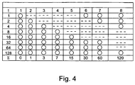
- the comparison table is therefore designed so that, depending on elapsed time during the movement of the gate thus initially, in the case according to FIG. 2 the comparison table can take the values 0, 1, 3, 7 and 15. Subsequently, however, the comparison table does not assume the value 31 but the value 30, since the first light barrier is opened again. The next value is 60 because the first and second photocells are opened, ie 63 - 1 -2. Accordingly, the next value of the comparison table is 120.
Landscapes
- Engineering & Computer Science (AREA)
- Structural Engineering (AREA)
- Architecture (AREA)
- Civil Engineering (AREA)
- Power-Operated Mechanisms For Wings (AREA)
- Operating, Guiding And Securing Of Roll- Type Closing Members (AREA)
- Geophysics And Detection Of Objects (AREA)
Claims (13)
- Dispositif de sécurité pour empêcher un élément mobile guidé pouvant être déplacé d'entrer accidentellement en collision avec un objet (9) situé sur un parcours de déplacement de l'élément mobile (2, 2a, 2b, 2c), lequel dispositif comporte au moins deux capteurs (4a, 4b, 4c, 4d, 4e) destinés à détecter l'objet et l'élément mobile et à émettre des signaux en fonction de la détection, ainsi qu'une unité d'exploitation (K) destinée à exploiter les signaux des capteurs et à générer un signal de mise à l'arrêt en fonction de l'exploitation, l'unité d'exploitation étant conçue pour saisir un vecteur d'état (6a, 6b, 6c, 6d, 6e), qui représente la totalité des signaux de toutes les sorties des capteurs actuellement détecté des deux capteurs ou plus parmi un ensemble de vecteurs d'état, lesquels contiennent de façon univoque toutes les combinaisons possibles des signaux des capteurs, et pour générer le signal de mise à l'arrêt (7) dans le cas de vecteurs d'état prédéterminés, l'unité d'exploitation étant conçue pour, à partir d'un ensemble de vecteurs d'états, lesquels contiennent les signaux de chaque capteur en fonction de la position de ces derniers, affecter au moyen d'une bijection d'une manière univoque et précise à chaque vecteur d'état une information d'état à partir d'un ensemble cible prédéterminé, et dans le cas d'informations d'état prédéterminées, de générer le signal de mise à l'arrêt, caractérisé en ce que l'unité d'exploitation est conçue :- pour affecter à chaque capteur une valeur numérique en fonction de sa position et de son signal et pour assembler le vecteur d'état à partir de ces valeurs numériques, et- pour exécuter la bijection comme opération mathématique des valeurs numériques, en particulier comme une addition, de sorte qu'une valeur résultante correspondante soit obtenue en tant qu'information d'état,une unité de mémoire étant présente dans laquelle peut être mémorisé un tableau comparatif comprenant des nombres de comparaison, lesquels correspondent aux vecteurs d'état prédéterminés, et l'unité d'exploitation étant conçue pour comparer la valeur résultante déterminée aux nombres de comparaison du tableau comparatif et, en fonction de cela, pour générer le signal de mise à l'arrêt, l'unité d'exploitation étant conçue de préférence pour affecter à chacun des capteurs la valeur numérique zéro, lorsque le capteur n'est pas interrompu, et pour mettre en oeuvre l'affectation de la valeur numérique en fonction du capteur respectif avec au total N capteurs (N ≥ 2 ; N : nombre entier naturel) selon la position que le capteur occupe à l'intérieur de l'agencement des N capteurs, l'unité d'exploitation étant conçue en particulier pour affecter la valeur numérique 2n-1 (2 puissance (n-1)) au nième capteur (n = 1, 2, ... N) à l'intérieur de l'agencement des capteurs.
- Dispositif de sécurité selon la revendication 1, caractérisé en ce que l'unité d'exploitation est conçue pour utiliser des vecteurs d'état prédéterminés et pour comparer un vecteur d'état actuellement détecté aux vecteurs d'état prédéterminés et pour générer le signal de mise à l'arrêt dans le cas de vecteurs d'état prédéterminés.
- Dispositif de sécurité selon l'une des revendications précédentes, caractérisé en ce que l'unité d'exploitation est conçue pour mémoriser au moins temporairement au moins un vecteur d'état détecté avant le vecteur d'état actuellement détecté et pour le comparer au vecteur d'état actuellement détecté.
- Dispositif de sécurité selon l'une des revendications précédentes, caractérisé en ce qu'une horloge est présente, laquelle peut être activée au moment de la mise en mouvement de l'élément mobile et peut être arrêtée au moment de l'arrêt du déplacement de l'élément mobile, l'horloge étant conçue pour transmettre une valeur temporelle à l'unité d'exploitation.
- Dispositif de sécurité selon l'une des revendications précédentes, caractérisé en ce que l'unité d'exploitation est conçue pour déterminer les vecteurs d'état prédéterminés pour la génération du signal de mise à l'arrêt à l'aide de la valeur temporelle.
- Dispositif de sécurité selon l'une des revendications précédentes, caractérisé en ce que l'unité d'exploitation est conçue pour affecter en plus aux signaux et/ou aux valeurs résultantes une valeur temporelle qui correspond au moment de la détection, l'unité d'exploitation comportant une horloge qui peut être activée au moment de la mise en mouvement de l'élément mobile et peut être arrêtée au moment de l'arrêt du déplacement de l'élément mobile, de sorte que l'horloge mesure le temps déjà écoulé pendant le mouvement de l'élément mobile, et l'unité d'exploitation étant conçue pour calculer, en fonction de la valeur temporaire, une valeur théorique qui découlerait des signaux des capteurs interrompus lors d'un fonctionnement normal, et pour comparer la valeur résultante à la valeur théorique et, en fonction de cela, pour générer le signal de mise à l'arrêt.
- Dispositif de sécurité selon l'une des revendications précédentes, caractérisé en ce que le capteur est conçu comme une barrière à rayonnement, en particulier comme une barrière lumineuse en barrage ou comme une barrière lumineuse par réflexion ou comme un capteur de temps de vol (TOF).
- Dispositif de sécurité selon l'une des revendications précédentes, caractérisé en ce que les capteurs sont disposés parallèlement au sens du déplacement (5) de l'élément mobile (2) et/ou dans le plan du déplacement (8) de l'élément mobile (2).
- Dispositif de sécurité selon l'une des revendications précédentes, caractérisé en ce que les capteurs sont orientés perpendiculairement au sens du déplacement (5) de l'élément mobile (2).
- Dispositif de sécurité selon l'une des revendications précédentes, caractérisé en ce que l'unité d'exploitation est conçue pour interrompre le déplacement de l'élément mobile en présence du signal de mise à l'arrêt.
- Dispositif de sécurité selon l'une des revendications précédentes, caractérisé en ce que l'unité d'exploitation est conçue pour mettre en oeuvre de façon répétée la comparaison avec le tableau comparatif pendant le déplacement de l'élément mobile.
- Dispositif de fermeture (1) comprenant un élément mobile guidé pouvant être déplacé et un dispositif de sécurité selon l'une des revendications précédentes, au moins un des capteurs étant disposé de sorte qu'il peut détecter l'élément mobile lorsque celui effectue un déplacement.
- Unité d'exploitation pour exploiter les capteurs d'un dispositif de sécurité et générer un signal de mise à l'arrêt pour mettre à l'arrêt l'entraînement de l'élément mobile, l'unité d'exploitation et le dispositif de sécurité étant conçus selon l'une des revendications précédentes.
Priority Applications (4)
| Application Number | Priority Date | Filing Date | Title |
|---|---|---|---|
| DK11008656.8T DK2586959T4 (en) | 2011-10-28 | 2011-10-28 | Safety device, closure and evaluation unit |
| US13/284,005 US8988213B2 (en) | 2011-10-28 | 2011-10-28 | Safety device, closing device and evaluation unit |
| EP11008656.8A EP2586959B2 (fr) | 2011-10-28 | 2011-10-28 | Dispositif de sécurisation, dispositif de fermeture et unité d'évaluation |
| CN201210548388.XA CN103089109B (zh) | 2011-10-28 | 2012-10-26 | 安全装置、关闭装置以及评估单元 |
Applications Claiming Priority (1)
| Application Number | Priority Date | Filing Date | Title |
|---|---|---|---|
| EP11008656.8A EP2586959B2 (fr) | 2011-10-28 | 2011-10-28 | Dispositif de sécurisation, dispositif de fermeture et unité d'évaluation |
Publications (3)
| Publication Number | Publication Date |
|---|---|
| EP2586959A1 EP2586959A1 (fr) | 2013-05-01 |
| EP2586959B1 EP2586959B1 (fr) | 2013-12-25 |
| EP2586959B2 true EP2586959B2 (fr) | 2016-09-14 |
Family
ID=45065575
Family Applications (1)
| Application Number | Title | Priority Date | Filing Date |
|---|---|---|---|
| EP11008656.8A Active EP2586959B2 (fr) | 2011-10-28 | 2011-10-28 | Dispositif de sécurisation, dispositif de fermeture et unité d'évaluation |
Country Status (4)
| Country | Link |
|---|---|
| US (1) | US8988213B2 (fr) |
| EP (1) | EP2586959B2 (fr) |
| CN (1) | CN103089109B (fr) |
| DK (1) | DK2586959T4 (fr) |
Cited By (2)
| Publication number | Priority date | Publication date | Assignee | Title |
|---|---|---|---|---|
| US10844646B2 (en) | 2018-02-27 | 2020-11-24 | Cedes Ag | Light grid with distance information to distinguish between a normal case and a safety case between a door edge and an object |
| WO2020244710A1 (fr) | 2019-06-05 | 2020-12-10 | Eurodoors Production GmbH | Système de porte pourvu d'un dispositif pour la détection de collisions |
Families Citing this family (15)
| Publication number | Priority date | Publication date | Assignee | Title |
|---|---|---|---|---|
| DK2506034T3 (da) * | 2011-04-01 | 2013-09-02 | Cedes Ag | Sensorindretning, sikkerhedsindretning, dør og fremgangsmåde til kontrol af bevægelsen |
| EP2845985B1 (fr) | 2013-07-18 | 2015-11-18 | Cedes Ag | Système de sécurisation de porte |
| CN106537181B (zh) * | 2014-04-03 | 2019-12-03 | 伊沃夫科技有限公司 | 用于雷达的特征提取 |
| JP2015214794A (ja) * | 2014-05-08 | 2015-12-03 | 文化シヤッター株式会社 | 開閉装置の開閉体停止装置 |
| CN104453681A (zh) * | 2014-11-19 | 2015-03-25 | 无锡悟莘科技有限公司 | 一种基于感应的门帘转动控制方法 |
| JP6421043B2 (ja) * | 2015-01-16 | 2018-11-07 | 文化シヤッター株式会社 | 開閉装置 |
| DE102015101017B4 (de) * | 2015-01-23 | 2018-02-22 | Efaflex Tor- Und Sicherheitssysteme Gmbh & Co. Kg | Verfahren zur Steuerung einer Toranordnung sowie derartige Toranordnung und eine Sicherheitseinrichtung hierfür |
| US20220228420A1 (en) * | 2015-09-14 | 2022-07-21 | Rytec Corporation | System and method for safety management in roll-up doors |
| US10619397B2 (en) * | 2015-09-14 | 2020-04-14 | Rytec Corporation | System and method for safety management in roll-up doors |
| DE102018104313A1 (de) * | 2018-02-26 | 2019-08-29 | Marantec Antriebs- Und Steuerungstechnik Gmbh & Co. Kg | Verfahren zum Bestimmen der Torposition bei einer Toranlage |
| DE102018104314A1 (de) * | 2018-02-26 | 2019-08-29 | Marantec Antriebs- Und Steuerungstechnik Gmbh & Co. Kg | Toranlage |
| WO2020005080A1 (fr) * | 2018-06-29 | 2020-01-02 | Turinsky Wilfried Manfred | Dispositif de sécurité destiné à être utilisé avec un appareil de renvoi de panneau et une plaqueuse de chant |
| US11346141B2 (en) | 2018-12-21 | 2022-05-31 | Rytec Corporation | Safety system and method for overhead roll-up doors |
| EP3680814B1 (fr) * | 2019-01-14 | 2024-10-09 | dormakaba Deutschland GmbH | Procédé de détection des déroulements de mouvements et système de détection correspondant |
| US12098582B2 (en) | 2019-08-27 | 2024-09-24 | Marantec Antriebs-Und Steuerungstechnik Gmbh & Co. Kg | Method for determining a position of a door in a door system |
Citations (5)
| Publication number | Priority date | Publication date | Assignee | Title |
|---|---|---|---|---|
| EP0789182A1 (fr) † | 1996-02-10 | 1997-08-13 | Hermann Wegener | Dispositif de sécurité dans une machine-outil à main, notamment d'une presse plieuse |
| DE29912572U1 (de) † | 1999-07-19 | 1999-09-16 | Marantec Antriebs- und Steuerungstechnik GmbH & Co. KG, 33428 Marienfeld | Vorrichtung zum Öffnen bzw. Schließen eines Tores |
| DE10203145C1 (de) † | 2002-01-28 | 2003-04-17 | Efaflex Tor & Sicherheitssys | Einrichtung zur automatischen Betätigung eines Tores, insbesondere eines Hubtores |
| DE102007050334A1 (de) † | 2007-10-18 | 2009-04-23 | Efaflex Tor- Und Sicherheitssysteme Gmbh & Co. Kg | Verfahren und Einrichtung zur Steuerung eines vertikal oder horizontal bewegten Tores unter Absicherung der Torschließebene gegenüber Hindernissen |
| EP2374985A2 (fr) † | 2010-04-08 | 2011-10-12 | Strack Lift Automation GmbH | Porte motorisée dotée d'un dispositif de sécurité |
Family Cites Families (13)
| Publication number | Priority date | Publication date | Assignee | Title |
|---|---|---|---|---|
| US5233185A (en) * | 1992-02-28 | 1993-08-03 | Gmi Holdings, Inc. | Light beam detector for door openers using fiber optics |
| US5583405A (en) * | 1994-08-11 | 1996-12-10 | Nabco Limited | Automatic door opening and closing system |
| DE19739543A1 (de) | 1997-09-09 | 1999-03-11 | Efaflex Inzeniring D O O Ljubl | Sicherheitseinrichtung für motorisch angetriebene Tore |
| DE29901664U1 (de) * | 1999-02-03 | 1999-04-15 | Samaco GmbH, 77694 Kehl | Hubtor mit Lichtgitter-Überwachungseinrichtung |
| GB2353855B (en) * | 1999-08-23 | 2002-02-20 | Airdri Ltd | Gap scanning |
| DE102005003794A1 (de) | 2005-01-26 | 2006-08-03 | Cedes Ag | Vorrichtung zur Absicherung eines angetriebenen Bewegungselements |
| US7532709B2 (en) * | 2005-02-04 | 2009-05-12 | Styers Justin R | Remote garage door monitoring system |
| DE202006002000U1 (de) * | 2006-02-08 | 2006-04-06 | Adolf Seuster Gmbh & Co. Kg | Tor mit Lichtschrankenanordnung |
| EP1983135A4 (fr) * | 2006-02-08 | 2011-08-03 | Nabtesco Corp | Unité de porte automatique |
| US8752032B2 (en) * | 2007-02-23 | 2014-06-10 | Irdeto Canada Corporation | System and method of interlocking to protect software-mediated program and device behaviours |
| DE102008023294B4 (de) * | 2008-01-16 | 2010-02-04 | Cedes Ag | Sicherungssystem zur Absicherung eines sich bewegenden, geführten Bewegungselements gegen ungewollte Kollisionen |
| EP2226452B1 (fr) * | 2008-12-12 | 2014-05-14 | Pepperl + Fuchs GmbH | Capteur de surveillance de porte |
| PL2236732T3 (pl) * | 2009-03-17 | 2015-06-30 | Seuster Kg | Brama |
-
2011
- 2011-10-28 DK DK11008656.8T patent/DK2586959T4/en active
- 2011-10-28 EP EP11008656.8A patent/EP2586959B2/fr active Active
- 2011-10-28 US US13/284,005 patent/US8988213B2/en active Active
-
2012
- 2012-10-26 CN CN201210548388.XA patent/CN103089109B/zh active Active
Patent Citations (5)
| Publication number | Priority date | Publication date | Assignee | Title |
|---|---|---|---|---|
| EP0789182A1 (fr) † | 1996-02-10 | 1997-08-13 | Hermann Wegener | Dispositif de sécurité dans une machine-outil à main, notamment d'une presse plieuse |
| DE29912572U1 (de) † | 1999-07-19 | 1999-09-16 | Marantec Antriebs- und Steuerungstechnik GmbH & Co. KG, 33428 Marienfeld | Vorrichtung zum Öffnen bzw. Schließen eines Tores |
| DE10203145C1 (de) † | 2002-01-28 | 2003-04-17 | Efaflex Tor & Sicherheitssys | Einrichtung zur automatischen Betätigung eines Tores, insbesondere eines Hubtores |
| DE102007050334A1 (de) † | 2007-10-18 | 2009-04-23 | Efaflex Tor- Und Sicherheitssysteme Gmbh & Co. Kg | Verfahren und Einrichtung zur Steuerung eines vertikal oder horizontal bewegten Tores unter Absicherung der Torschließebene gegenüber Hindernissen |
| EP2374985A2 (fr) † | 2010-04-08 | 2011-10-12 | Strack Lift Automation GmbH | Porte motorisée dotée d'un dispositif de sécurité |
Cited By (2)
| Publication number | Priority date | Publication date | Assignee | Title |
|---|---|---|---|---|
| US10844646B2 (en) | 2018-02-27 | 2020-11-24 | Cedes Ag | Light grid with distance information to distinguish between a normal case and a safety case between a door edge and an object |
| WO2020244710A1 (fr) | 2019-06-05 | 2020-12-10 | Eurodoors Production GmbH | Système de porte pourvu d'un dispositif pour la détection de collisions |
Also Published As
| Publication number | Publication date |
|---|---|
| CN103089109B (zh) | 2016-12-28 |
| US20130106601A1 (en) | 2013-05-02 |
| CN103089109A (zh) | 2013-05-08 |
| DK2586959T4 (en) | 2017-01-09 |
| EP2586959B1 (fr) | 2013-12-25 |
| DK2586959T3 (en) | 2014-03-17 |
| EP2586959A1 (fr) | 2013-05-01 |
| US8988213B2 (en) | 2015-03-24 |
Similar Documents
| Publication | Publication Date | Title |
|---|---|---|
| EP2586959B2 (fr) | Dispositif de sécurisation, dispositif de fermeture et unité d'évaluation | |
| EP2506034B1 (fr) | Dispositif de capteur, dispositif de sécurité, porte et procédé de contrôle du mouvement | |
| EP1841942B1 (fr) | Dispositif pour sécuriser un élément mobile entraîné | |
| DE102006008513A1 (de) | Sensor-Überwachungseinrichtung | |
| DE102010017398B3 (de) | Verfahren zum Betrieb eines Tores sowie Vorrichtung zum Betrieb eines Tores | |
| DE102008044990A1 (de) | Verfahren und Vorrichtung zur Ansteuerung und/oder Überwachung eines motorisch angetriebenen Flügels während der Öffnungsphase | |
| EP2404859A1 (fr) | Dispositif de surveillance pour sécuriser un élément entraîné | |
| EP2799384A1 (fr) | Porte motorisée dotée d'un dispositif de sécurité | |
| DE102010014806B4 (de) | Torantriebsvorrichtung, damit versehener Gebäudeabschluss, Torsystem und Herstell- und Antriebsverfahren | |
| EP0678649A1 (fr) | Volet roulant et dispositif de contrôle | |
| DE102019126718A1 (de) | Einrichtung zur gebäudefesten installation mit wenigstens einem automatisch bewegbaren flügelelement und verfahren hierzu | |
| EP3004717B1 (fr) | Porte d'ascenseur dotée d'un commutateur de contact de porte | |
| EP2204891B1 (fr) | Mécanisme de commande d'un composant de véhicule automobile et procédé de fonctionnement d'un tel mécanisme de commande | |
| DE4337015B4 (de) | Verfahren zur Steuerung eines motorischen Antriebs einer Tür- oder Fensteranlage | |
| EP4013933B1 (fr) | Procédé de détermination de la position d'une porte dans un système de porte | |
| EP2845985B1 (fr) | Système de sécurisation de porte | |
| EP2943630B1 (fr) | Ensemble capteur de proximité capacitif sur une porte d'un véhicule automobile pour détecter un mouvement d'approche approximativement horizontal d'une main d'opérateur | |
| EP2694766B1 (fr) | Procédé de commande d'un mécanisme d'entraînement de porte | |
| DE102011102232A1 (de) | Lichtgitter | |
| EP0446651A2 (fr) | Système d'actionnement électropneumatique de porte de véhicule de transport de passagers | |
| EP1048812B1 (fr) | Méthode pour normaliser la position de la vitre d'un lève-vitre de véhicule actionné par une force exterieure | |
| DE102018210516A1 (de) | Sensorsystem zum Absichern beweglicher Objekte und Verfahren zum Betreiben eines Sensorsystems | |
| WO2007039198A1 (fr) | Dispositif de commande de mecanisme de reglage de vehicule automobile | |
| DE102004052056B4 (de) | Sicherheitsschalteranordnung | |
| DE102011102963A1 (de) | Verfahren zur Inbetriebnahme von automatischen Türanlagen sowie zugehörige Vorrichtung |
Legal Events
| Date | Code | Title | Description |
|---|---|---|---|
| PUAI | Public reference made under article 153(3) epc to a published international application that has entered the european phase |
Free format text: ORIGINAL CODE: 0009012 |
|
| 17P | Request for examination filed |
Effective date: 20111028 |
|
| AK | Designated contracting states |
Kind code of ref document: A1 Designated state(s): AL AT BE BG CH CY CZ DE DK EE ES FI FR GB GR HR HU IE IS IT LI LT LU LV MC MK MT NL NO PL PT RO RS SE SI SK SM TR |
|
| AX | Request for extension of the european patent |
Extension state: BA ME |
|
| RBV | Designated contracting states (corrected) |
Designated state(s): AL AT BE BG CH CY CZ DE DK EE ES FI FR GB GR HR HU IE IS IT LI LT LU LV MC MK MT NL NO PL PT RO RS SE SI SK SM TR |
|
| GRAP | Despatch of communication of intention to grant a patent |
Free format text: ORIGINAL CODE: EPIDOSNIGR1 |
|
| INTG | Intention to grant announced |
Effective date: 20130829 |
|
| GRAS | Grant fee paid |
Free format text: ORIGINAL CODE: EPIDOSNIGR3 |
|
| GRAA | (expected) grant |
Free format text: ORIGINAL CODE: 0009210 |
|
| AK | Designated contracting states |
Kind code of ref document: B1 Designated state(s): AL AT BE BG CH CY CZ DE DK EE ES FI FR GB GR HR HU IE IS IT LI LT LU LV MC MK MT NL NO PL PT RO RS SE SI SK SM TR |
|
| REG | Reference to a national code |
Ref country code: GB Ref legal event code: FG4D Free format text: NOT ENGLISH |
|
| REG | Reference to a national code |
Ref country code: CH Ref legal event code: EP |
|
| REG | Reference to a national code |
Ref country code: AT Ref legal event code: REF Ref document number: 646769 Country of ref document: AT Kind code of ref document: T Effective date: 20140115 |
|
| REG | Reference to a national code |
Ref country code: IE Ref legal event code: FG4D Free format text: LANGUAGE OF EP DOCUMENT: GERMAN |
|
| REG | Reference to a national code |
Ref country code: DE Ref legal event code: R096 Ref document number: 502011001862 Country of ref document: DE Effective date: 20140220 |
|
| REG | Reference to a national code |
Ref country code: CH Ref legal event code: NV Representative=s name: KELLER AND PARTNER PATENTANWAELTE AG, CH |
|
| REG | Reference to a national code |
Ref country code: NL Ref legal event code: T3 |
|
| REG | Reference to a national code |
Ref country code: DK Ref legal event code: T3 Effective date: 20140314 |
|
| PG25 | Lapsed in a contracting state [announced via postgrant information from national office to epo] |
Ref country code: NO Free format text: LAPSE BECAUSE OF FAILURE TO SUBMIT A TRANSLATION OF THE DESCRIPTION OR TO PAY THE FEE WITHIN THE PRESCRIBED TIME-LIMIT Effective date: 20140325 Ref country code: LT Free format text: LAPSE BECAUSE OF FAILURE TO SUBMIT A TRANSLATION OF THE DESCRIPTION OR TO PAY THE FEE WITHIN THE PRESCRIBED TIME-LIMIT Effective date: 20131225 Ref country code: FI Free format text: LAPSE BECAUSE OF FAILURE TO SUBMIT A TRANSLATION OF THE DESCRIPTION OR TO PAY THE FEE WITHIN THE PRESCRIBED TIME-LIMIT Effective date: 20131225 Ref country code: HR Free format text: LAPSE BECAUSE OF FAILURE TO SUBMIT A TRANSLATION OF THE DESCRIPTION OR TO PAY THE FEE WITHIN THE PRESCRIBED TIME-LIMIT Effective date: 20131225 Ref country code: SE Free format text: LAPSE BECAUSE OF FAILURE TO SUBMIT A TRANSLATION OF THE DESCRIPTION OR TO PAY THE FEE WITHIN THE PRESCRIBED TIME-LIMIT Effective date: 20131225 |
|
| REG | Reference to a national code |
Ref country code: LT Ref legal event code: MG4D |
|
| PG25 | Lapsed in a contracting state [announced via postgrant information from national office to epo] |
Ref country code: RS Free format text: LAPSE BECAUSE OF FAILURE TO SUBMIT A TRANSLATION OF THE DESCRIPTION OR TO PAY THE FEE WITHIN THE PRESCRIBED TIME-LIMIT Effective date: 20131225 Ref country code: LV Free format text: LAPSE BECAUSE OF FAILURE TO SUBMIT A TRANSLATION OF THE DESCRIPTION OR TO PAY THE FEE WITHIN THE PRESCRIBED TIME-LIMIT Effective date: 20131225 |
|
| PG25 | Lapsed in a contracting state [announced via postgrant information from national office to epo] |
Ref country code: EE Free format text: LAPSE BECAUSE OF FAILURE TO SUBMIT A TRANSLATION OF THE DESCRIPTION OR TO PAY THE FEE WITHIN THE PRESCRIBED TIME-LIMIT Effective date: 20131225 Ref country code: IS Free format text: LAPSE BECAUSE OF FAILURE TO SUBMIT A TRANSLATION OF THE DESCRIPTION OR TO PAY THE FEE WITHIN THE PRESCRIBED TIME-LIMIT Effective date: 20140425 |
|
| PG25 | Lapsed in a contracting state [announced via postgrant information from national office to epo] |
Ref country code: RO Free format text: LAPSE BECAUSE OF FAILURE TO SUBMIT A TRANSLATION OF THE DESCRIPTION OR TO PAY THE FEE WITHIN THE PRESCRIBED TIME-LIMIT Effective date: 20131225 Ref country code: ES Free format text: LAPSE BECAUSE OF FAILURE TO SUBMIT A TRANSLATION OF THE DESCRIPTION OR TO PAY THE FEE WITHIN THE PRESCRIBED TIME-LIMIT Effective date: 20131225 Ref country code: PT Free format text: LAPSE BECAUSE OF FAILURE TO SUBMIT A TRANSLATION OF THE DESCRIPTION OR TO PAY THE FEE WITHIN THE PRESCRIBED TIME-LIMIT Effective date: 20140428 Ref country code: SK Free format text: LAPSE BECAUSE OF FAILURE TO SUBMIT A TRANSLATION OF THE DESCRIPTION OR TO PAY THE FEE WITHIN THE PRESCRIBED TIME-LIMIT Effective date: 20131225 Ref country code: CY Free format text: LAPSE BECAUSE OF FAILURE TO SUBMIT A TRANSLATION OF THE DESCRIPTION OR TO PAY THE FEE WITHIN THE PRESCRIBED TIME-LIMIT Effective date: 20131225 Ref country code: CZ Free format text: LAPSE BECAUSE OF FAILURE TO SUBMIT A TRANSLATION OF THE DESCRIPTION OR TO PAY THE FEE WITHIN THE PRESCRIBED TIME-LIMIT Effective date: 20131225 |
|
| REG | Reference to a national code |
Ref country code: DE Ref legal event code: R026 Ref document number: 502011001862 Country of ref document: DE |
|
| PLBI | Opposition filed |
Free format text: ORIGINAL CODE: 0009260 |
|
| 26 | Opposition filed |
Opponent name: SICK AG Effective date: 20140919 |
|
| PLAX | Notice of opposition and request to file observation + time limit sent |
Free format text: ORIGINAL CODE: EPIDOSNOBS2 |
|
| PG25 | Lapsed in a contracting state [announced via postgrant information from national office to epo] |
Ref country code: PL Free format text: LAPSE BECAUSE OF FAILURE TO SUBMIT A TRANSLATION OF THE DESCRIPTION OR TO PAY THE FEE WITHIN THE PRESCRIBED TIME-LIMIT Effective date: 20131225 |
|
| REG | Reference to a national code |
Ref country code: DE Ref legal event code: R026 Ref document number: 502011001862 Country of ref document: DE Effective date: 20140919 |
|
| PLBB | Reply of patent proprietor to notice(s) of opposition received |
Free format text: ORIGINAL CODE: EPIDOSNOBS3 |
|
| REG | Reference to a national code |
Ref country code: CH Ref legal event code: PCAR Free format text: NEW ADDRESS: EIGERSTRASSE 2 POSTFACH, 3000 BERN 14 (CH) |
|
| PG25 | Lapsed in a contracting state [announced via postgrant information from national office to epo] |
Ref country code: MC Free format text: LAPSE BECAUSE OF FAILURE TO SUBMIT A TRANSLATION OF THE DESCRIPTION OR TO PAY THE FEE WITHIN THE PRESCRIBED TIME-LIMIT Effective date: 20131225 Ref country code: LU Free format text: LAPSE BECAUSE OF FAILURE TO SUBMIT A TRANSLATION OF THE DESCRIPTION OR TO PAY THE FEE WITHIN THE PRESCRIBED TIME-LIMIT Effective date: 20141028 Ref country code: SI Free format text: LAPSE BECAUSE OF FAILURE TO SUBMIT A TRANSLATION OF THE DESCRIPTION OR TO PAY THE FEE WITHIN THE PRESCRIBED TIME-LIMIT Effective date: 20131225 |
|
| PG25 | Lapsed in a contracting state [announced via postgrant information from national office to epo] |
Ref country code: BE Free format text: LAPSE BECAUSE OF NON-PAYMENT OF DUE FEES Effective date: 20141031 |
|
| REG | Reference to a national code |
Ref country code: IE Ref legal event code: MM4A |
|
| REG | Reference to a national code |
Ref country code: FR Ref legal event code: ST Effective date: 20150630 |
|
| PG25 | Lapsed in a contracting state [announced via postgrant information from national office to epo] |
Ref country code: FR Free format text: LAPSE BECAUSE OF NON-PAYMENT OF DUE FEES Effective date: 20141031 |
|
| PG25 | Lapsed in a contracting state [announced via postgrant information from national office to epo] |
Ref country code: IE Free format text: LAPSE BECAUSE OF NON-PAYMENT OF DUE FEES Effective date: 20141028 |
|
| PGFP | Annual fee paid to national office [announced via postgrant information from national office to epo] |
Ref country code: CH Payment date: 20151021 Year of fee payment: 5 |
|
| PGFP | Annual fee paid to national office [announced via postgrant information from national office to epo] |
Ref country code: NL Payment date: 20151021 Year of fee payment: 5 |
|
| RIC2 | Information provided on ipc code assigned after grant |
Ipc: E06B 9/68 20060101ALI20160122BHEP Ipc: E06B 9/88 20060101AFI20160122BHEP |
|
| PG25 | Lapsed in a contracting state [announced via postgrant information from national office to epo] |
Ref country code: SM Free format text: LAPSE BECAUSE OF FAILURE TO SUBMIT A TRANSLATION OF THE DESCRIPTION OR TO PAY THE FEE WITHIN THE PRESCRIBED TIME-LIMIT Effective date: 20131225 |
|
| GBPC | Gb: european patent ceased through non-payment of renewal fee |
Effective date: 20151028 |
|
| PG25 | Lapsed in a contracting state [announced via postgrant information from national office to epo] |
Ref country code: IT Free format text: LAPSE BECAUSE OF FAILURE TO SUBMIT A TRANSLATION OF THE DESCRIPTION OR TO PAY THE FEE WITHIN THE PRESCRIBED TIME-LIMIT Effective date: 20131225 Ref country code: GR Free format text: LAPSE BECAUSE OF FAILURE TO SUBMIT A TRANSLATION OF THE DESCRIPTION OR TO PAY THE FEE WITHIN THE PRESCRIBED TIME-LIMIT Effective date: 20140326 Ref country code: BG Free format text: LAPSE BECAUSE OF FAILURE TO SUBMIT A TRANSLATION OF THE DESCRIPTION OR TO PAY THE FEE WITHIN THE PRESCRIBED TIME-LIMIT Effective date: 20131225 |
|
| PG25 | Lapsed in a contracting state [announced via postgrant information from national office to epo] |
Ref country code: TR Free format text: LAPSE BECAUSE OF FAILURE TO SUBMIT A TRANSLATION OF THE DESCRIPTION OR TO PAY THE FEE WITHIN THE PRESCRIBED TIME-LIMIT Effective date: 20131225 Ref country code: HU Free format text: LAPSE BECAUSE OF FAILURE TO SUBMIT A TRANSLATION OF THE DESCRIPTION OR TO PAY THE FEE WITHIN THE PRESCRIBED TIME-LIMIT; INVALID AB INITIO Effective date: 20111028 Ref country code: GB Free format text: LAPSE BECAUSE OF NON-PAYMENT OF DUE FEES Effective date: 20151028 Ref country code: MT Free format text: LAPSE BECAUSE OF FAILURE TO SUBMIT A TRANSLATION OF THE DESCRIPTION OR TO PAY THE FEE WITHIN THE PRESCRIBED TIME-LIMIT Effective date: 20131225 |
|
| PUAH | Patent maintained in amended form |
Free format text: ORIGINAL CODE: 0009272 |
|
| STAA | Information on the status of an ep patent application or granted ep patent |
Free format text: STATUS: PATENT MAINTAINED AS AMENDED |
|
| 27A | Patent maintained in amended form |
Effective date: 20160914 |
|
| AK | Designated contracting states |
Kind code of ref document: B2 Designated state(s): AL AT BE BG CH CY CZ DE DK EE ES FI FR GB GR HR HU IE IS IT LI LT LU LV MC MK MT NL NO PL PT RO RS SE SI SK SM TR |
|
| REG | Reference to a national code |
Ref country code: DE Ref legal event code: R102 Ref document number: 502011001862 Country of ref document: DE |
|
| REG | Reference to a national code |
Ref country code: CH Ref legal event code: AELC |
|
| REG | Reference to a national code |
Ref country code: DK Ref legal event code: T4 Effective date: 20170104 |
|
| REG | Reference to a national code |
Ref country code: NL Ref legal event code: MP Effective date: 20131225 |
|
| PG25 | Lapsed in a contracting state [announced via postgrant information from national office to epo] |
Ref country code: NL Free format text: LAPSE BECAUSE OF FAILURE TO SUBMIT A TRANSLATION OF THE DESCRIPTION OR TO PAY THE FEE WITHIN THE PRESCRIBED TIME-LIMIT Effective date: 20131225 |
|
| REG | Reference to a national code |
Ref country code: CH Ref legal event code: PL |
|
| PG25 | Lapsed in a contracting state [announced via postgrant information from national office to epo] |
Ref country code: LI Free format text: LAPSE BECAUSE OF NON-PAYMENT OF DUE FEES Effective date: 20161031 Ref country code: CH Free format text: LAPSE BECAUSE OF NON-PAYMENT OF DUE FEES Effective date: 20161031 |
|
| REG | Reference to a national code |
Ref country code: AT Ref legal event code: MM01 Ref document number: 646769 Country of ref document: AT Kind code of ref document: T Effective date: 20161028 |
|
| PG25 | Lapsed in a contracting state [announced via postgrant information from national office to epo] |
Ref country code: AT Free format text: LAPSE BECAUSE OF NON-PAYMENT OF DUE FEES Effective date: 20161028 |
|
| PG25 | Lapsed in a contracting state [announced via postgrant information from national office to epo] |
Ref country code: MK Free format text: LAPSE BECAUSE OF FAILURE TO SUBMIT A TRANSLATION OF THE DESCRIPTION OR TO PAY THE FEE WITHIN THE PRESCRIBED TIME-LIMIT Effective date: 20131225 |
|
| PG25 | Lapsed in a contracting state [announced via postgrant information from national office to epo] |
Ref country code: AL Free format text: LAPSE BECAUSE OF FAILURE TO SUBMIT A TRANSLATION OF THE DESCRIPTION OR TO PAY THE FEE WITHIN THE PRESCRIBED TIME-LIMIT Effective date: 20131225 |
|
| P01 | Opt-out of the competence of the unified patent court (upc) registered |
Effective date: 20230519 |
|
| PGFP | Annual fee paid to national office [announced via postgrant information from national office to epo] |
Ref country code: DK Payment date: 20231025 Year of fee payment: 13 Ref country code: DE Payment date: 20231018 Year of fee payment: 13 |