EP2845985B1 - Torsicherungssystem - Google Patents
Torsicherungssystem Download PDFInfo
- Publication number
- EP2845985B1 EP2845985B1 EP13003615.5A EP13003615A EP2845985B1 EP 2845985 B1 EP2845985 B1 EP 2845985B1 EP 13003615 A EP13003615 A EP 13003615A EP 2845985 B1 EP2845985 B1 EP 2845985B1
- Authority
- EP
- European Patent Office
- Prior art keywords
- gate
- signal
- designed
- safety system
- edge
- Prior art date
- Legal status (The legal status is an assumption and is not a legal conclusion. Google has not performed a legal analysis and makes no representation as to the accuracy of the status listed.)
- Active
Links
Images

Classifications
-
- E—FIXED CONSTRUCTIONS
- E06—DOORS, WINDOWS, SHUTTERS, OR ROLLER BLINDS IN GENERAL; LADDERS
- E06B—FIXED OR MOVABLE CLOSURES FOR OPENINGS IN BUILDINGS, VEHICLES, FENCES OR LIKE ENCLOSURES IN GENERAL, e.g. DOORS, WINDOWS, BLINDS, GATES
- E06B9/00—Screening or protective devices for wall or similar openings, with or without operating or securing mechanisms; Closures of similar construction
- E06B9/56—Operating, guiding or securing devices or arrangements for roll-type closures; Spring drums; Tape drums; Counterweighting arrangements therefor
- E06B9/80—Safety measures against dropping or unauthorised opening; Braking or immobilising devices; Devices for limiting unrolling
- E06B9/82—Safety measures against dropping or unauthorised opening; Braking or immobilising devices; Devices for limiting unrolling automatic
- E06B9/88—Safety measures against dropping or unauthorised opening; Braking or immobilising devices; Devices for limiting unrolling automatic for limiting unrolling
-
- E—FIXED CONSTRUCTIONS
- E05—LOCKS; KEYS; WINDOW OR DOOR FITTINGS; SAFES
- E05F—DEVICES FOR MOVING WINGS INTO OPEN OR CLOSED POSITION; CHECKS FOR WINGS; WING FITTINGS NOT OTHERWISE PROVIDED FOR, CONCERNED WITH THE FUNCTIONING OF THE WING
- E05F15/00—Power-operated mechanisms for wings
- E05F15/40—Safety devices, e.g. detection of obstructions or end positions
- E05F15/42—Detection using safety edges
- E05F15/43—Detection using safety edges responsive to disruption of energy beams, e.g. light or sound
- E05F2015/434—Detection using safety edges responsive to disruption of energy beams, e.g. light or sound with cameras or optical sensors
- E05F2015/435—Detection using safety edges responsive to disruption of energy beams, e.g. light or sound with cameras or optical sensors by interruption of the beam
- E05F2015/436—Detection using safety edges responsive to disruption of energy beams, e.g. light or sound with cameras or optical sensors by interruption of the beam the beam being parallel to the wing edge
-
- E—FIXED CONSTRUCTIONS
- E05—LOCKS; KEYS; WINDOW OR DOOR FITTINGS; SAFES
- E05Y—INDEXING SCHEME ASSOCIATED WITH SUBCLASSES E05D AND E05F, RELATING TO CONSTRUCTION ELEMENTS, ELECTRIC CONTROL, POWER SUPPLY, POWER SIGNAL OR TRANSMISSION, USER INTERFACES, MOUNTING OR COUPLING, DETAILS, ACCESSORIES, AUXILIARY OPERATIONS NOT OTHERWISE PROVIDED FOR, APPLICATION THEREOF
- E05Y2900/00—Application of doors, windows, wings or fittings thereof
- E05Y2900/10—Application of doors, windows, wings or fittings thereof for buildings or parts thereof
- E05Y2900/106—Application of doors, windows, wings or fittings thereof for buildings or parts thereof for garages
-
- E—FIXED CONSTRUCTIONS
- E06—DOORS, WINDOWS, SHUTTERS, OR ROLLER BLINDS IN GENERAL; LADDERS
- E06B—FIXED OR MOVABLE CLOSURES FOR OPENINGS IN BUILDINGS, VEHICLES, FENCES OR LIKE ENCLOSURES IN GENERAL, e.g. DOORS, WINDOWS, BLINDS, GATES
- E06B9/00—Screening or protective devices for wall or similar openings, with or without operating or securing mechanisms; Closures of similar construction
- E06B9/56—Operating, guiding or securing devices or arrangements for roll-type closures; Spring drums; Tape drums; Counterweighting arrangements therefor
- E06B9/68—Operating devices or mechanisms, e.g. with electric drive
- E06B2009/6809—Control
- E06B2009/6818—Control using sensors
- E06B2009/6827—Control using sensors sensing light
-
- E—FIXED CONSTRUCTIONS
- E06—DOORS, WINDOWS, SHUTTERS, OR ROLLER BLINDS IN GENERAL; LADDERS
- E06B—FIXED OR MOVABLE CLOSURES FOR OPENINGS IN BUILDINGS, VEHICLES, FENCES OR LIKE ENCLOSURES IN GENERAL, e.g. DOORS, WINDOWS, BLINDS, GATES
- E06B9/00—Screening or protective devices for wall or similar openings, with or without operating or securing mechanisms; Closures of similar construction
- E06B9/56—Operating, guiding or securing devices or arrangements for roll-type closures; Spring drums; Tape drums; Counterweighting arrangements therefor
- E06B9/68—Operating devices or mechanisms, e.g. with electric drive
- E06B2009/6809—Control
- E06B2009/6872—Control using counters to determine shutter position
Definitions
- the invention relates to a Torêtssystem with a light grid arrangement for the detection of objects in the plane of movement of the gate and the gate edge wherein the security system between gate and object.
- Tornells of the type mentioned are known from the prior art. These usually form a grid of light barriers within the plane of movement of the door and transversely to the direction of movement of the leading gate edge.
- the photoelectric barriers are formed by a transmitter strip and a receiver strip which are provided opposite each other for mounting on or in the guide of the gate edge, so that the gate interrupts the photoelectric barriers successively when closing.
- the known Torommessysteme offer a method with which a distinction can be made between the detection of an object or the gate edge.
- the 2011 filed patent application EP 2 586 959 A1 CEDES AG describes a Torzzissystem in which the pattern detected by the receiver bar is statically compared with predefined patterns in order to be able to immediately distinguish between object and gate edge even after a failure and restart of the Torinerungssystems.
- the 2011 filed patent application EP 2 506 034 A1 CEDES AG describes a Torellesssystem, in which the light grid is formed of distance sensors and is distinguished on the basis of the detected distance between the object and the door edge.
- a disadvantage is the aforementioned Torommessystemen with the exception of CEDES EP 2 229 496 B1 and the CEDES EP 2 506 034 A1 in that the tamper-evident system can be manipulated by inserting a narrow object, such as a rod or an arm, below the gate edge in the path of the gate in such a way that it interrupts only the photocell closest to the gate edge.
- a narrow object such as a rod or an arm
- the torching system usually recognizes this as a door edge and not as an object. As a result, the object can be damaged and squeezed in particular by the completely closing gate on the ground.
- the inventive gate securing system serves to protect a gate with a gate edge slidably leading in a plane of movement and in a movement direction against collision with an object and comprises a light grid direction with at least 2 transmitting elements and at least 2 Receiving elements for the formation of light barrier beams in the plane of motion for detecting an object in the plane of movement and the gate edge and further comprises an evaluation device which is adapted to distinguish due to the detection of the light grid device between the object or gate edge and to generate a security signal upon detection of an object and further comprises a position sensor device which is formed separately from the light grid device for detecting a position of the gate and for outputting a position signal which corresponds to a position range of the gate edge, wherein the evaluation device is further adapted to generate a check signal due to the interruption of a particular light barrier beam of the light grid device and wherein there is further provided a control device which is designed to carry out a plausibility check as a function of the position signal and the checking signal gnal and generate a safety signal depending on the plaus
- the Torzzissystem can have the advantage that when an incorrect distinction of the evaluation that incorrectly assigns the gate edge instead of an object as a cause and therefore incorrectly generates no security signal in an incorrect detection of the light grid device, the Torommessystem still responds safely because now instead of the evaluation, the control device can generate the safety signal.
- the safety of the door safety system can be increased.
- the position signal may preferably be a value from a range of values.
- the check signal may preferably be associated with the position of a light grid steel.
- the evaluation device can preferably generate an associated characteristic checking signal, which is assigned to the respective positions of the light grating bars, in each case for a plurality of light grid beams when interrupted
- the evaluation device is adapted to generate due to the interruption of a particular light barrier beam of the light grid device, a verification signal which is associated with the particular Licht-enstrahl characteristically and a position range of the gate edge on the line of the particular Licht-enstrahls or between the particular Licht 2enstrahl and the closed position of the door corresponds and Furthermore, the control device is designed to transmit the safety signal generate when the position signal corresponding position range is outside the position corresponding to the check signal position range
- the particular light barrier should be interrupted by the gate edge or, if the gate body also breaks the light barrier beams in the plane of movement, by the subsequent gate leaves. Then, the position signal should reflect a position of the gate edge at the particular light barrier beam or between the particular light barrier and the closed position of the door. If this is not the case, then there is an unsafe condition of the gate, so that a safety signal is ore eugt.
- the door bodies In sectional doors, the door bodies usually have sectional sections of a certain depth, which usually interrupt the light barrier beams. In the case of film doors, the door body usually has a thin film which usually does not interrupt the light barrier beams.
- the position sensor device preferably comprises a rotary encoder and / or one or more end-zone switches.
- the efficiency of the Torschssystems can be increased.
- Rotary encoders can be mounted on the drive shaft of the gate and determine the position of the gate edge by means of the unwinding rotation of the gate.
- End-of-range switches can act as a cam or curve on the gate edge or the gate body on a switch on the door guide and thus determine the position or a position range of the gate edge.
- the Torellesssystem further comprises a control device in particular for position-dependent control of the speed of movement of the door and / or in particular for the position-dependent deactivation of a hose edge safety at the gate edge.
- the position sensor device is designed to pass signals to at least one further control device, in particular for position-dependent control of the speed of movement of the door and / or in particular for the position-dependent deactivation of a hose edge safety device at the gate edge.
- the position-dependent speed control may allow about a deceleration before the closing position.
- the Torommessystem can have the advantage that it increases the comfort for the user.
- the evaluation device is connected to the light grid device by a common carrier, in particular by a common housing.
- the control device is connected to the drive control of the door or also connected to the light grid device by a common carrier, in particular by a common housing.
- a common carrier or housing can facilitate assembly and increase ruggedness.
- the Torellesssystem can facilitate the assembly and / or increase the robustness against wear.
- the light grid arrangement is formed so that the particular light barrier beam is disposed at a height between 2 cm and 30 cm, in particular between 5 cm and 20 cm, in particular between 10 cm and 15 cm above the ground.
- a low location of the particular beam of light beam can reduce the risk of crushing.
- the lowest light beam beam is not selected so that a slowing down of the gate is still possible.
- the Torellesssystem can reduce the risk of crushing.
- the position sensor device is designed such that the output of the position signal takes place when detecting the gate about +/- 20 cm, in particular about +/- 10 cm, in particular about +/- 5 cm, in particular about +/- 1 cm, in particular exactly at the position of the gate when the gate edge enters the specific light barrier.
- the position sensor device is preferably designed so that the output of the position signal takes place during a certain period of time after which the door has reached a specific position.
- the range tolerant output of the position signal may increase the stability of the plausibility check.
- the Torschssystem can increase the system stability.
- the position sensor device is configured to record the position of the gate associated with a position signal by a learning run of the gate, wherein in particular the one or more check signals are used to detect and / or store the position of the gate,
- the gate can close approximately from top to bottom and when passing and interrupting the or the particular light beam beams, the or the corresponding verification signals are passed to the control device that connects them in their memory with the or simultaneously incoming position signals.
- the position signals can represent values from a value range that corresponds to the travel path of the gate.
- the Torellesssystem and / or the evaluation device and / or the control device is adapted to stop the gate when the safety signal generated and / or reverse.
- the inventive gate comprises a Torschssystem invention of the aforementioned type.
- the inventive gate can have the advantages of Torschssystems.
- Fig. 1 shows a gate 1 with a Torellesssystem 2 with a End Schlschalter 3 on which a cam curve 4 acts.
- the cam operates the end range switch when the gate edge 5 is in an area between the particular light barrier beam 6 and the ground.
- a light grid device 7 consists of a transmitter strip 8 with transmitters 9 and a receiver strip 10 with receivers 11 assigned in parallel.
- the light barrier beams 12 are interrupted by the gate, the specific light barrier beam 6 is interrupted by an object and the light barrier beam 13 is not interrupted.
- the receivers are connected by a connection 14 to the evaluation device 15, which is located in the housing 16 of the light grid device 7.
- the evaluation device is connected to the motor controller 17 via a connection 18 via which a security signal can be sent.
- the receiver 19 of the specific light barrier beam 6 is connected to the control device 21 via a connection 20.
- the end range switch 3 is connected to the control device 21 via a connection 22.
- the control device 21 is connected to the motor controller 17 and can also transmit this to a safety signal.
- the motor controller 17 is connected to the motor 23 which drives the door 1 by rolling or rolling over the shaft 24. The motor control stops and reverses the rolling motor in case of a safety signal.
- the object 25 interrupts the determined light beam beam 6. This leads to the detection by the associated receiver 19 and to the generation of a specific light beam beam associated with the verification signal which is transmitted via the connection 20 to the control device.
- the End Schlsschalter 3 is not yet switched by the cam curve 4 of the gate. This circuit state of a position of the gate edge 5 even before the specific light barrier beam 6 and is transmitted as a position signal to the control device 21.
- the control device has the position corresponding to the check signal and the position range corresponding to the position signal stored in the memory. The control device now compares the check signal with the position signal for plausibility as to whether the position range corresponding to the check signal lies within the position range of the position signal.
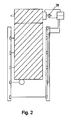
- Fig. 2 shows the gate 1 with a Torellesssystem 2 with a rotary encoder 26 which is connected to the control device 21.
- the rotary encoder detects the rotation of the shaft 24 and transmits the rotation to the control device.
- the control unit calculates the position of the gate and the gate edge from the rotational values. The position corresponding to the gate edge on the particular beam steel 6 is entered or taught the control device.
- the other structure and mode of action correspond FIG. 1 ,
Landscapes
- Engineering & Computer Science (AREA)
- Structural Engineering (AREA)
- Architecture (AREA)
- Civil Engineering (AREA)
- Power-Operated Mechanisms For Wings (AREA)
Description
- Die Erfindung betrifft ein Torsicherungssystem mit einer Lichtgitteranordnung zur Detektion von Objekten in der Bewegungsebene des Tors und der Torkante wobei das Sicherungssystem zwischen Tor und Objekt unterscheidet.
- Aus dem Stand der Technik sind Torsicherungssysteme der genannten Art bekannt. Diese bilden üblicherweise ein Gitter aus Lichtschranken innerhalb der Bewegungsebene des Tors und quer zur Bewegungsrichtung der vorlaufenden Torkante aus. Im Allgemeinen werden die Lichtschranken durch eine Senderleiste und eine Empfängerleiste gebildet welche gegenüberliegend jeweils zur Montage an oder in der Führung der Torkante vorgesehen sind, sodass das Tor beim Schliessen die Lichtschranken nacheinander unterbricht. Dazu bieten die bekannten Torsicherungssysteme ein Verfahren an, mit dem zwischen der Detektion eines Objekts oder der Torkante unterschieden werden kann.
- Das 1998 angemeldete Patent
EP 0 902 157 B1 der EFAFLEX Transport und Lagertechnik GmbH beschreibt ein Torsicherungssystem, bei dem den Lichtschranken sequenziell in Bewegungsrichtung drei unterschiedliche Zustände dynamisch in Abhängigkeit von den zuvor zugeordneten Zuständen zugeordnet werden wobei die nächste vor der Torkante liegende Lichtschranke stets deaktiviert ist. - Das 2006 angemeldete Patent
EP 1 841 942 B1 der CEDES AG beschreibt ein Torsicherungssystem, bei dem die nächste von der Torkante zu überfahrende Lichtschranke in Abhängigkeit von der Fahrzeit der Torkante zwischen den Lichtschranken kurzzeitig vor dem Überfahren der Torkante deaktiviert wird, um eine längere Sensitivität für die Objekterkennung zu gewährleisten. - Das 2009 angemeldete Patent
EP 2 229 496 B1 der CEDES AG beschreibt ein Torsicherungssystem, bei dem die Empfängerleiste zusätzliche Sendeelemente umfasst, die zusammen mit den Empfangselementen der Empfängerleiste und über einen an der Torkante vorhandenen Reflektor die Lage der Torkante detektieren, um eine Manipulation des Torsicherungssystems sicher auszuschliessen. - Die 2011 angemeldete Patentanmeldung
EP 2 586 959 A1 der CEDES AG beschreibt ein Torsicherungssystem, bei dem das von der Empfängerleiste detektierte Muster statisch mit vordefinierten Mustern verglichen wird, um auch nach einem Ausfall und Wiederanfahren des Torsicherungssystems sofort zwischen Objekt und Torkante unterscheiden zu können. - Die 2011 angemeldete Patentanmeldung
EP 2 506 034 A1 der CEDES AG beschreibt ein Torsicherungssystem, bei dem das Lichtgitter aus Entfernungssensoren gebildet ist und aufgrund der detektierten Entfernung zwischen Objekt und Torkante unterschieden wird. - Nachteilig ist den genannten Torsicherungssystemen mit Ausnahme der CEDES
EP 2 229 496 B1 und der CEDESEP 2 506 034 A1 , dass das Torsicherungssystem dadurch manipuliert werden kann, dass ein schmales Objekt, etwa eine Stange oder ein Arm, unterhalb der Torkante so in den Weg des Tores eingebracht wird, dass es nur die der Torkante nächstliegende noch zu überfahrende Lichtschranke unterbricht. Diese Torsicherungssysteme unterscheiden zwischen Torkante und Objekt im Wesentlichen dadurch, dass die von der Torkante bereits unterbrochenen Lichtschranken ebenso wie die der Torkante nächstliegende noch nicht unterbrochene Lichtschranke nicht oder nicht ununterbrochen zur Objektdetektion genutzt wird. Wird dabei das Objekt von der Torkante weg nach unten geführt oder von der Torkante nach unten gedrückt, so erkennt das Torsicherungssystem dieses üblicherweise als Torkante und nicht als Objekt. Dadurch kann das Objekt beschädigt werden und insbesondere vom vollständig schliessenden Tor am Boden gequetscht werden. - Es ist Aufgabe der Erfindung ein verbessertes Torsicherungssystem bereit zu stellen.
- Diese Aufgabe wird, ausgehend von Torsicherungssystemen der eingangs genannten Art, durch ein Torsicherungssystem nach Anspruch 1 und ein Tor nach Anspruch 10 gelöst. Vorteilhafte Ausgestaltungen sind in den weiteren abhängigen Ansprüchen angegeben.
- Das erfindungsgemässe Torsicherungssystem dient zur Absicherung eines Tors mit einer in einer Bewegungsebene und in einer Bewegungsrichtung verschiebbar vorlaufenden Torkante gegen Kollision mit einem Objekt und umfasst eine Lichtgittereimichtung mit mindestens 2 Sendeelementen und mit mindestens 2 Empfangselementen zur Ausbildung von Lichtschrankenstrahlen in der Bewegungsebene zur Detektion eines Objekts in der Bewegungsebene und der Torkante und umfasst des Weiteren eine Auswerteeinrichtung, die dazu ausgebildet ist aufgrund der Detektion der Lichtgittereinrichtung zwischen Objekt oder Torkante zu unterscheiden und bei Detektion eines Objekts ein Sicherheitssignal zu erzeugen und umfasst des Weiteren eine Positionssensoreinrichtung die getrennt von der Lichtgittereinrichtung ausgebildet ist zur Detektion einer Position des Tors und zur Ausgabe eines Positionssignals das einem Positionsbereich der Torkante entspricht wobei die Auswerteeinrichtung weiterhin dazu ausgebildet ist, aufgrund der Unterbrechung eines bestimmten Lichtschrankenstrahls der Lichtgittereinrichtung ein Überprüfungssignal zu erzeugen und wobei des Weiteren eine Kontrolleinrichtung vorhanden ist, die dazu ausgebildet ist, eine Plausibilitätsprüfung in Abhängigkeit von Positionssignal und Überprüfungssignal durchzuführen und in Abhängigkeit von der Plausibilitätsprüfung ein Sicherheitssignal zu erzeugen.
- Das Torsicherungssystem kann den Vorteil haben, dass bei einer unkorrekten Unterscheidung der Auswerteeinrichtung, die einer Detektion der Lichtgittereinrichtung unkorrekter Weise die Torkante anstatt ein Objekt als Ursache zuordnet und daher unkorrekt kein Sicherheitssignal erzeugt, das Torsicherungssystem dennoch sicher reagiert, da nun anstatt der Auswerteeinrichtung die Kontrolleinrichtung das Sicherheitssignal erzeugen kann. Die Sicherheit des Torsicherheitssystems kann erhöht werden.
- Das Positionssignal kann vorzugsweise ein Wert aus einem Wertebereich sein. Das Überprüfungssignal kann vorzugsweise der Position eines Lichtgitterstahls zugeordnet sein. Die Auswerteeinrichtung kann vorzugsweise mehreren Lichtgitterstrahlen bei Unterbrechung jeweils ein zugeordnetes charakteristisches Überprüfungssignal erzeugen, das den jeweiligen Positionen der Lichtgitterstahlen zugeordnet ist
- Vorzugsweise ist die Auswerteeinrichtung dazu ausgebildet, aufgrund der Unterbrechung eines bestimmten Lichtschrankenstrahls der Lichtgittereinrichtung ein Überprüfungssignal zu erzeugen das dem bestimmten Lichtschrankenstrahl charakteristisch zugeordnet ist und einem Positionsbereich der Torkante an der Linie des bestimmten Lichtschrankenstrahls oder zwischen dem bestimmten Lichtschrankenstrahl und der geschlossen Stellung des Tors entspricht und/oder des Weiteren die Kontrolleinrichtung dazu ausgebildet, das Sicherheitssignal zu erzeugen wenn der dem Positionssignal entsprechende Positionsbereich ausserhalb des dem Überprüfungssignal entsprechenden Positionsbereich liegt
- Wenn das Überprüfungssignal erzeugt ist, sollte die bestimmte Lichtschranke von der Torkante oder, falls der Torkörper ebenfalls die Lichtschrankenstrahlen in der Bewegungsebene unterbrechen von den nachfolgenden Torblättem unterbrochen sein. Dann sollte das Positionssignal eine Position der Torkante an dem bestimmten Lichtschrankenstrahl oder zwischen der bestimmten Lichtschranke und der geschlossen Stellung des Tors wiedergeben. Ist dem nicht so, so liegt ein unsicherer Zustand des Tors vor, sodass ein Sicherheitssignal erz eugt wird.
- Bei Sektionaltoren weisen der Torkörper üblicherweise Sektionalabschnitte von gewisser Tiefe auf, die die Lichtschrankenstrahlen üblicherweise unterbrechen. Bei Folientoren weist der Torkörper üblicherweise eine dünne Folie auf, die die Lichtschrankenstrahlen üblicherweise nicht unterbrechen.
- Vorzugsweise umfasst die Positionssensoreinrichtung einen Drehgeber und/oder einen oder mehrere Endbereichsschalter.
- Dies kann den Vorteil haben, dass die Positionssensoreinrichtung mehrfach Verwendung findet. Die Wirtschaftlichkeit des Torsicherungssystems kann erhöht werden.
- Drehgeber können an der Antriebswelle des Tors angebracht sein und über die Abrolldrehung des Tores die Position der Torkante bestimmen.
- Endbereichsschalter können als Nocke oder Kurve auf der Torkante oder dem Torkörper an einen Schalter an der Torführung angreifen und so die Position oder einen Positionsbereich der Torkante bestimmen.
- Vorzugsweise umfasst das Torsicherungssystem eine weitere Steuereinrichtung insbesondere zur positionsabhängigen Steuerung der Geschwindigkeit der Bewegung des Tors und/oder insbesondere zur positionsabhängigen Deaktivierung einer Schlauchkantensicherung an der Torkante. Vorzugsweise ist die Positionssensoreinrichtung dazu ausgebildet Signale an mindestens eine weitere Steuereinrichtung weiterzugeben insbesondere zur positionsabhängigen Steuerung der Geschwindigkeit der Bewegung des Tors und/oder insbesondere zur positionsabhängigen Deaktivierung einer Schlauchkantensicherung an der Torkante.
- Die positionsabhängige Geschwindigkeitssteuerung kann etwa ein Abbremsen vor der Schliessposition ermöglichen. Das Torsicherungssystem kann den Vorteil haben, dass es den Komfort für den Nutzer erhöht.
- Vorzugsweise ist die Auswerteeinrichtung mit der Lichtgittereinrichtung durch einem gemeinsamen Träger verbunden ist, insbesondere von einem gemeinsamen Gehäuse umfasst. Vorzugsweise ist die Kontrolleinrichtung mit der Antriebssteuerung des Tors oder ebenfalls mit der Lichtgittereinrichtung durch einem gemeinsamen Träger verbunden, insbesondere von einem gemeinsamen Gehäuse umfasst.
- Ein gemeinsamer Träger oder Gehäuse kann die Montage erleichtern und die Robustheit erhöhen. Das Torsicherungssystem kann die Montage erleichtern und/oder die Robustheit gegen Verschleiss erhöhen.
- Vorzugsweise die Lichtgitteranordnung so ausgebildet, dass der bestimmte Lichtschrankenstrahl in einer Höhe zwischen 2 cm und 30 cm, insbesondere zwischen 5 cm und 20 cm, insbesondere zwischen 10 cm und 15 cm über dem Boden angeordnet ist.
- Eine niedrige Anordnung des bestimmten Lichtschrankenstrahls kann die Gefahr eines Einquetschens vermindern. Vorzugsweise wird nicht der unterste Lichtschrankenstrahl gewählt, damit ein Abbremsen des Tor noch sinnvoll möglich ist. Das Torsicherungssystem kann die Gefahr des Einquetschens verringern.
- Vorzugsweise ist die Positionssensoreinrichtung so ausgebildet, dass die Ausgabe des Positionssignals erfolgt bei der Detektion des Tores etwa +/-20 cm, insbesondere etwa +/-10 cm, insbesondere etwa +/-5 cm, insbesondere etwa +/-1 cm, insbesondere genau um die Position des Tores bei Eintritt der Torkante in die bestimmte Lichtschranke. Vorzugsweise ist die Positionssensoreinrichtung so ausgebildet, dass die Ausgabe des Positionssignals während einer bestimmten Zeitdauer erfolgt nach der das Tor eine bestimmte Position erreicht hat.
- Die Bereichstolerante Ausgabe des Positionssignals kann die Stabilität der Plausibilitätsprüfung erhöhen. Das Torsicherungssystem kann die Systemstabilität erhöhen.
- Vorzugsweise ist die Positionssensoreinrichtung dazu ausgebildet, die einem Positionssignal zugeordnete Position des Tor durch eine Lernfahrt des Tores aufzunehmen, wobei insbesondere das oder die Überprüfungssignale zur Erkennung und/oder Speicherung der Position des Tors herangezogen werden,
- Dabei kann das Tor sich etwa von oben nach unten schliessen wobei beim Überfahren und Unterbrechen des oder der bestimmten Lichtschrankenstrahlen, das oder die entsprechenden Überprüfungssignale an die Kontrolleinrichtung weitergegeben werden, die diese in ihrem Speicher mit dem oder den zeitgleich eingehenden Positionssignalen verbindet. Die Positionssignale können Werte aus einem Wertebereich darstellen, der dem Fahrweg des Tors entspricht.
- Dies kann den Aufwand bei der Inbetriebnahme verringern.
- Vorzugsweise ist das Torsicherungssystem und/oder die Auswerteeinrichtung und/oder die Kontrolleinrichtung dazu ausgebildet, das Tor bei erzeugtem Sicherheitssignal zu stoppen und/oder zu reversieren.
- Das erfindungsgemässe Tor umfasst ein erfindungsgemässes Torsicherungssystem der vorgenannten Art.
- Das erfindungsgemässe Tor kann die Vorteile des Torsicherungssystems aufweisen.
- Weitere Merkmale der Erfindung sind in den Zeichnungen angegeben.
- Die jeweils genannten Vorteile können sich auch für Merkmalskombinationen realisieren in deren Zusammenhang sie nicht genannt sind.
- Ausführungsbeispiele der Erfindung sind in den Zeichnungen dargestellt und werden im Folgenden näher erläutert. Gleiche Bezugszeichen in den einzelnen Figuren bezeichnen dabei einander entsprechende Elemente. Es zeigen
- Fig. 1
- ein Tor mit Torsicherungssystem und Endbereichsschalter und
- Fig. 2
- ein Tor mit Torsicherungssystem und Drehgeber.
-
Fig. 1 zeigt ein Tor 1 mit einem Torsicherungssystem 2 mit einem Endbereichsschalter 3 auf den eine Nockenkurve 4 wirkt. Der Nocken betätigt den Endbereichsschalter wenn die Torkante 5 in einem Bereich zwischen dem bestimmten Lichtschrankenstrahl 6 und dem Boden ist. Eine Lichtgittervorrichtung 7 besteht aus einer Senderleiste 8 mit Sendern 9 und mit einer Empfängerleiste 10 mit parallel zugeordneten Empfängern 11. Die Lichtschrankenstrahlen 12 sind durch das Tor unterbrochen, der bestimmte Lichtschrankenstrahl 6 ist durch ein Objekt unterbrochen und der Lichtschrankenstrahl 13 ist nicht unterbrochen. Die Empfänger sind mit einer Verbindung 14 mit der Auswerteeinrichtung 15 verbunden die sich im Gehäuse 16 der Lichtgittereinrichtung 7 befindet. Die Auswerteeinrichtung ist mit der Motorsteuerung 17 über eine Verbindung 18 verbunden über welche ein Sicherheitssignal gesendet werden kann. Der Empfänger 19 des bestimmten Lichtschrankenstrahls 6 ist über eine Verbindung 20 mit der Kontrolleinrichtung 21 verbunden. Der Endbereichsschalter 3 ist über eine Verbindung 22 mit der Kontrolleinrichtung 21 verbunden. Die Kontrolleinrichtung 21 ist mit der Motorsteuerung 17 verbunden und kann dieser ebenfalls ein Sicherheitssignal übermitteln. Die Motorsteuerung 17 ist mit dem Motor 23 verbunden welcher das Tor 1 durch Aufrollen oder Abrollen über die Welle 24 antreibt. Die Motorsteuerung stoppt und reversiert den abrollenden Motor im Falle eines Sicherheitssignals. - Das Objekt 25 unterbricht den bestimmten Lichtschrankenstrahl 6. Dies führt zur Detektion durch den zugeordneten Empfänger 19 und zur Erzeugung eines dem bestimmten Lichtschrankenstrahl zugeordneten Überprüfungssignals das über die Verbindung 20 an die Kontrolleinrichtung übermittelt wird. Der Endbereichsschalter 3 ist noch nicht durch die Nockenkurve 4 des Tors geschalten. Dieser Schaltungszustand einer Position der Torkante 5 noch vor dem bestimmten Lichtschrankenstrahl 6 und wird als Positionssignal an die Kontrolleinrichtung 21 übermittelt. Der Kontrolleinrichtung ist die dem Überprüfungssignal entsprechende Position sowie der dem Positionssignal entsprechende Positionsbereich im Speicher hinterlegt. Die Kontrolleinrichtung vergleicht nun das Überprüfungssignal mit dem Positionssignal auf Plausibilität ob der dem Überprüfungssignal entsprechende Positionsbereich innerhalb des Positionsbereichs des Positionssignals liegt. Im vorliegenden Fall ist dies nicht der Fall, da das Objekt 25 und nicht die Torkante den bestimmten Lichtschrankenstrahl 6 unterbricht. Weil der dem Positionssignal entsprechende Positionsbereich ausserhalb des dem Überprüfungssignal entsprechenden Positionsbereich liegt erzeugt die Kontrolleinrichtung 21 ein Sicherheitssignal das der Motorsteuerung 17 übermittelt wird, welche den Motor 23 und das Tor 1 stoppt und reversiert
-
Fig. 2 zeigt das Tor 1 mit einem Torsicherungssystem 2 mit einem Drehgeber 26 der mit der der Kontrolleinrichtung 21 verbunden ist. Der Drehgeber detektiert die Drehung der Welle 24 und übermittelt die Drehung an die Kontrolleinrichtung. Die Kontrolleinrichtung errechnet aus den Drehwerten die Position des Tors und der Torkante. Die Position die der Torkante am bestimmten Lichtstrahlenstahl 6 entspricht wird der Kontrolleinrichtung eingegeben oder eingelernt. Der sonstige Aufbau und Wirkungsweise entsprechenFigur 1 .
Claims (10)
- Torsicherungssystem- zur Absicherung eines Tors mit einer in einer Bewegungsebene und in einer Bewegungsrichtung verschiebbar vorlaufenden Torkante gegen Kollision mit einem Objekt, umfassend- eine Lichtgittereinrichtung- mit mindestens 2 Sendeelementen und mit mindestens 2 Empfangselementen- zur Ausbildung von Lichtschrankenstrahlen in der Bewegungsebene- zur Detektion eines Objekts in der Bewegungsebene und der Torkante;- eine Auswerteeinrichtung, die dazu ausgebildet ist- aufgrund der Detektion der Lichtgittereinrichtung- zwischen Objekt oder Torkante zu unterscheiden- und bei Detektion eines Objekts ein Sicherheitssignal zu erzeugen;- eine Positionssensoreinrichtungdadurch gekennzeichnet, dass- die getrennt von der Lichtgittereinrichtung ausgebildet ist- zur Detektion einer Position des Tors und- zur Ausgabe eines Positionssignals- das einem Positionsbereich der Torkante entspricht- die Auswerteeinrichtung weiterhin dazu ausgebildet ist,- aufgrund der Unterbrechung eines bestimmten Lichtschrankenstrahls der Lichtgittereinrichtung ein Überprüfungssignal zu erzeugen und- eine Kontrolleinrichtung vorhanden und dazu ausgebildet ist,- eine Plausibilitätsprüfung in Abhängigkeit von Positionssignal und Überprüfungssignal durchzuführen- und in Abhängigkeit von der Plausibilitätsprüfung ein Sicherheitssignal zu erzeugen.
- Torsicherungssystem nach Anspruch 1, dadurch gekennzeichnet dass- die Auswerteeinrichtung dazu ausgebildet ist,- aufgrund der Unterbrechung eines bestimmten Lichtschrankenstrahls der Lichtgittereinrichtung ein Überprüfungssignal zu erzeugen das dem bestimmten Lichtschrankenstrahl charakteristisch zugeordnet ist und einem Positionsbereich der Torkante an der Linie des bestimmten Lichtschrankenstrahls oder zwischen dem bestimmten Lichtschrankenstrahl und der geschlossen Stellung des Tors entspricht und/oder dass- die Kontrolleinrichtung dazu ausgebildet ist,- das Sicherheitssignal zu erzeugen- wenn die dem Positionssignal entsprechende Positionsbereich ausserhalb des dem Überprüfungssignal entsprechenden Positionsbereich liegt.
- Torsicherungssystem nach einem der vorgenannten Ansprüche,
dadurch gekennzeichnet dass- die Positionssensoreinrichtung- einen Drehgeber und/oder- einen oder mehrere Endbereichsschalter umfasst. - Torsicherungssystem nach einem der vorgenannten Ansprüche,
dadurch gekennzeichnet dass- das Torsicherungssystem eine weitere Steuereinrichtung umfasst- insbesondere zur positionsabhängigen Steuerung der Geschwindigkeit der Bewegung des Tors und/oder- insbesondere zur positionsabhängigen Deaktivierung einer Schlauchkantensicherung an der Torkante und/oder- die Positionssensoreinrichtung dazu ausgebildet ist- Signale an mindestens eine weitere Steuereinrichtung weiterzugeben- insbesondere zur positionsabhängigen. Steuerung der Geschwindigkeit der Bewegung des Tors und/oder- insbesondere zur positionsabhängigen Deaktivierung einer Schlauchkantensicherung an der Torkante. - Torsicherungssystem nach einem der vorgenannten Ansprüche,
dadurch gekennzeichnet dass- die Auswerteeinrichtung- mit der Lichtgittereinrichtung durch einem gemeinsamen Träger verbunden ist, insbesondere von einem gemeinsamen Gehäuse umfasst ist und/oder- die Kontrolleinrichtung- mit der Antriebssteuerung des Tors durch einem gemeinsamen Träger verbunden ist, insbesondere von einem gemeinsamen Gehäuse umfasst ist oder- ebenfalls mit der Lichtgittereinrichtung durch einem gemeinsamen Träger verbunden ist, insbesondere von einem gemeinsamen Gehäuse umfasst ist. - Torsicherungssystem nach einem der vorgenannten Ansprüche,
dadurch gekennzeichnet dass- die Lichtgitteranordnung so ausgebildet ist, dass- der bestimmte Lichtschrankenstrahl in einer Höhe zwischen 2 cm und 30 cm, insbesondere zwischen 5 cm und 20 cm, insbesondere zwischen 10 cm und 15 cm über dem Boden angeordnet ist. - Torsicherungssystem nach einem der vorgenannten Ansprüche,
dadurch gekennzeichnet dass- die Positionssensoreinrichtung so ausgebildet ist, dass- die Ausgabe des Positionssignals erfolgt bei der Detektion des Tores etwa +/-20 cm, insbesondere etwa +/-10 cm, insbesondere etwa +/-5 cm, insbesondere etwa +/-1 cm, insbesondere genau um die Position des Tores bei Eintritt der Torkante in die bestimmte Lichtschranke und/oder dass- die Ausgabe des Positionssignals während einer bestimmten Zeitdauer erfolgt nach der das Tor eine bestimmte Position erreicht hat. - Torsicherungssystem nach einem der vorgenannten Ansprüche,
dadurch gekennzeichnet dass- die Positionssensoreinrichtung dazu ausgebildet ist,- die einem Positionssignal zugeordnete Position des Tor durch eine Lernfahrt des Tores aufzunehmen,- wobei insbesondere das oder die Überprüfungssignale zur Erkennung und/oder Speicherung der Position des Tors herangezogen werden. - Torsicherungssystem nach einem der vorgenannten Ansprüche,
dadurch gekennzeichnet dass- das Torsicherungssystem und/oder die Auswerteeinrichtung und/oder die Kontrolleinrichtung dazu ausgebildet ist,- das Tor bei erzeugtem Sicherheitssignal zu stoppen und/oder zu reversieren. - Tor mit einem Torsicherungssystem nach einem der vorgenannten Ansprüche.
Priority Applications (2)
| Application Number | Priority Date | Filing Date | Title |
|---|---|---|---|
| DK13003615.5T DK2845985T3 (en) | 2013-07-18 | 2013-07-18 | Port Security System |
| EP13003615.5A EP2845985B1 (de) | 2013-07-18 | 2013-07-18 | Torsicherungssystem |
Applications Claiming Priority (1)
| Application Number | Priority Date | Filing Date | Title |
|---|---|---|---|
| EP13003615.5A EP2845985B1 (de) | 2013-07-18 | 2013-07-18 | Torsicherungssystem |
Publications (2)
| Publication Number | Publication Date |
|---|---|
| EP2845985A1 EP2845985A1 (de) | 2015-03-11 |
| EP2845985B1 true EP2845985B1 (de) | 2015-11-18 |
Family
ID=48875463
Family Applications (1)
| Application Number | Title | Priority Date | Filing Date |
|---|---|---|---|
| EP13003615.5A Active EP2845985B1 (de) | 2013-07-18 | 2013-07-18 | Torsicherungssystem |
Country Status (2)
| Country | Link |
|---|---|
| EP (1) | EP2845985B1 (de) |
| DK (1) | DK2845985T3 (de) |
Families Citing this family (2)
| Publication number | Priority date | Publication date | Assignee | Title |
|---|---|---|---|---|
| EP3530869B1 (de) * | 2018-02-27 | 2020-04-15 | Cedes AG | Lichtgitter mit distanzinformation und deren verwendung |
| FR3101911B1 (fr) * | 2019-10-09 | 2021-10-01 | Sofineco Soc Pour Letude Et Le Financement Dentreprises Industrielles Et Commerciales | Barre palpeuse virtuelle pour porte de manutention |
Family Cites Families (6)
| Publication number | Priority date | Publication date | Assignee | Title |
|---|---|---|---|---|
| DE19739543A1 (de) | 1997-09-09 | 1999-03-11 | Efaflex Inzeniring D O O Ljubl | Sicherheitseinrichtung für motorisch angetriebene Tore |
| DE102005003794A1 (de) | 2005-01-26 | 2006-08-03 | Cedes Ag | Vorrichtung zur Absicherung eines angetriebenen Bewegungselements |
| DE102008023294B4 (de) | 2008-01-16 | 2010-02-04 | Cedes Ag | Sicherungssystem zur Absicherung eines sich bewegenden, geführten Bewegungselements gegen ungewollte Kollisionen |
| DE102010017398B3 (de) * | 2010-06-16 | 2011-12-01 | Feig Electronic Gmbh | Verfahren zum Betrieb eines Tores sowie Vorrichtung zum Betrieb eines Tores |
| DK2506034T3 (da) | 2011-04-01 | 2013-09-02 | Cedes Ag | Sensorindretning, sikkerhedsindretning, dør og fremgangsmåde til kontrol af bevægelsen |
| US8988213B2 (en) | 2011-10-28 | 2015-03-24 | Cedes Ag | Safety device, closing device and evaluation unit |
-
2013
- 2013-07-18 EP EP13003615.5A patent/EP2845985B1/de active Active
- 2013-07-18 DK DK13003615.5T patent/DK2845985T3/en active
Also Published As
| Publication number | Publication date |
|---|---|
| DK2845985T3 (en) | 2016-02-29 |
| EP2845985A1 (de) | 2015-03-11 |
Similar Documents
| Publication | Publication Date | Title |
|---|---|---|
| EP2586959B2 (de) | Sicherungsvorrichtung, Schließvorrichtung und Auswerteeinheit | |
| EP2506034B1 (de) | Sensorvorrichtung, Sicherheitsvorrichtung, Tor und Verfahren zur Kontrolle der Bewegung | |
| DE3618692C2 (de) | ||
| EP1089030B1 (de) | Verfahren und Vorrichtung zum Überwachen eines Schutzbereichs | |
| EP2574718B1 (de) | Sicherungssystem zur Absicherung eines sich bewegenden, geführten Bewegungselements gegen ungewollte Kollisionen | |
| EP2404859B1 (de) | Überwachungsvorrichtung zur Absicherung eines angetriebenen Elements | |
| DE4201971A1 (de) | Verdunkelungsvorrichtung | |
| DE19739544A1 (de) | Sicherheitseinrichtung für motorisch angetriebene Systeme | |
| EP1972751A2 (de) | Überwachungseinrichtung für ein motorisch angetriebenes Tor | |
| WO2016116178A1 (de) | Verfahren zur steuerung einer toranordnung sowie derartige toranordnung und eine sicherheitseinrichtung hierfür | |
| DE102008044990A1 (de) | Verfahren und Vorrichtung zur Ansteuerung und/oder Überwachung eines motorisch angetriebenen Flügels während der Öffnungsphase | |
| DE102007033766A1 (de) | Lichtgitter | |
| DE10228930B4 (de) | Sensorvorrichtung für eine automatische Drehtüranlage | |
| EP2306063A2 (de) | Sicherheitssensor | |
| EP1841942B1 (de) | Vorrichtung zur absicherung eines angetriebenen bewegungselements | |
| EP2799384A1 (de) | Motorisch angetriebenes Tor mit einer Sicherheitseinrichtung | |
| EP2845985B1 (de) | Torsicherungssystem | |
| WO2011095474A1 (de) | Torantriebsvorrichtung, damit versehener gebäudeabschluss, torsystem und herstell- und antriebsverfahren | |
| DE102006008513A1 (de) | Sensor-Überwachungseinrichtung | |
| DE102013212518A1 (de) | Automatische Fenster- oder Türanlage | |
| EP3660251A1 (de) | Schutzvorrichtung, insbesondere industrietor | |
| DE60201287T2 (de) | Motorisierter Rolladen mit Vorrichtung zum Abschalten eines Motorantriebes bei Erkennung eines Hindernisses | |
| EP3074583B1 (de) | Verfahren zum betreiben eines industrietores mit krafterkennungseinrichtung | |
| DE102018103729A1 (de) | Optoelektronische Sicherheitsvorrichtung und Verfahren zum Überwachen einer Maschinenbewegung | |
| EP2634358B1 (de) | Intelligente Hinderniserkennung |
Legal Events
| Date | Code | Title | Description |
|---|---|---|---|
| 17P | Request for examination filed |
Effective date: 20130808 |
|
| AK | Designated contracting states |
Kind code of ref document: A1 Designated state(s): AL AT BE BG CH CY CZ DE DK EE ES FI FR GB GR HR HU IE IS IT LI LT LU LV MC MK MT NL NO PL PT RO RS SE SI SK SM TR |
|
| AX | Request for extension of the european patent |
Extension state: BA ME |
|
| PUAI | Public reference made under article 153(3) epc to a published international application that has entered the european phase |
Free format text: ORIGINAL CODE: 0009012 |
|
| RBV | Designated contracting states (corrected) |
Designated state(s): AL AT BE BG CH CY CZ DE DK EE ES FI FR GB GR HR HU IE IS IT LI LT LU LV MC MK MT NL NO PL PT RO RS SE SI SK SM TR |
|
| GRAP | Despatch of communication of intention to grant a patent |
Free format text: ORIGINAL CODE: EPIDOSNIGR1 |
|
| RIC1 | Information provided on ipc code assigned before grant |
Ipc: E06B 9/88 20060101ALI20150608BHEP Ipc: E06B 9/68 20060101AFI20150608BHEP |
|
| RAP1 | Party data changed (applicant data changed or rights of an application transferred) |
Owner name: CEDES AG Owner name: FRABA AG |
|
| INTG | Intention to grant announced |
Effective date: 20150715 |
|
| GRAS | Grant fee paid |
Free format text: ORIGINAL CODE: EPIDOSNIGR3 |
|
| GRAA | (expected) grant |
Free format text: ORIGINAL CODE: 0009210 |
|
| AK | Designated contracting states |
Kind code of ref document: B1 Designated state(s): AL AT BE BG CH CY CZ DE DK EE ES FI FR GB GR HR HU IE IS IT LI LT LU LV MC MK MT NL NO PL PT RO RS SE SI SK SM TR |
|
| REG | Reference to a national code |
Ref country code: GB Ref legal event code: FG4D Free format text: NOT ENGLISH |
|
| REG | Reference to a national code |
Ref country code: CH Ref legal event code: EP |
|
| REG | Reference to a national code |
Ref country code: AT Ref legal event code: REF Ref document number: 761680 Country of ref document: AT Kind code of ref document: T Effective date: 20151215 |
|
| REG | Reference to a national code |
Ref country code: IE Ref legal event code: FG4D Free format text: LANGUAGE OF EP DOCUMENT: GERMAN |
|
| REG | Reference to a national code |
Ref country code: DE Ref legal event code: R096 Ref document number: 502013001467 Country of ref document: DE |
|
| REG | Reference to a national code |
Ref country code: DK Ref legal event code: T3 Effective date: 20160222 |
|
| REG | Reference to a national code |
Ref country code: NL Ref legal event code: MP Effective date: 20160218 |
|
| REG | Reference to a national code |
Ref country code: LT Ref legal event code: MG4D |
|
| PG25 | Lapsed in a contracting state [announced via postgrant information from national office to epo] |
Ref country code: IS Free format text: LAPSE BECAUSE OF FAILURE TO SUBMIT A TRANSLATION OF THE DESCRIPTION OR TO PAY THE FEE WITHIN THE PRESCRIBED TIME-LIMIT Effective date: 20160318 Ref country code: ES Free format text: LAPSE BECAUSE OF FAILURE TO SUBMIT A TRANSLATION OF THE DESCRIPTION OR TO PAY THE FEE WITHIN THE PRESCRIBED TIME-LIMIT Effective date: 20151118 Ref country code: IT Free format text: LAPSE BECAUSE OF FAILURE TO SUBMIT A TRANSLATION OF THE DESCRIPTION OR TO PAY THE FEE WITHIN THE PRESCRIBED TIME-LIMIT Effective date: 20151118 Ref country code: NL Free format text: LAPSE BECAUSE OF FAILURE TO SUBMIT A TRANSLATION OF THE DESCRIPTION OR TO PAY THE FEE WITHIN THE PRESCRIBED TIME-LIMIT Effective date: 20151118 Ref country code: NO Free format text: LAPSE BECAUSE OF FAILURE TO SUBMIT A TRANSLATION OF THE DESCRIPTION OR TO PAY THE FEE WITHIN THE PRESCRIBED TIME-LIMIT Effective date: 20160218 Ref country code: HR Free format text: LAPSE BECAUSE OF FAILURE TO SUBMIT A TRANSLATION OF THE DESCRIPTION OR TO PAY THE FEE WITHIN THE PRESCRIBED TIME-LIMIT Effective date: 20151118 Ref country code: LT Free format text: LAPSE BECAUSE OF FAILURE TO SUBMIT A TRANSLATION OF THE DESCRIPTION OR TO PAY THE FEE WITHIN THE PRESCRIBED TIME-LIMIT Effective date: 20151118 |
|
| PG25 | Lapsed in a contracting state [announced via postgrant information from national office to epo] |
Ref country code: PL Free format text: LAPSE BECAUSE OF FAILURE TO SUBMIT A TRANSLATION OF THE DESCRIPTION OR TO PAY THE FEE WITHIN THE PRESCRIBED TIME-LIMIT Effective date: 20151118 Ref country code: FI Free format text: LAPSE BECAUSE OF FAILURE TO SUBMIT A TRANSLATION OF THE DESCRIPTION OR TO PAY THE FEE WITHIN THE PRESCRIBED TIME-LIMIT Effective date: 20151118 Ref country code: PT Free format text: LAPSE BECAUSE OF FAILURE TO SUBMIT A TRANSLATION OF THE DESCRIPTION OR TO PAY THE FEE WITHIN THE PRESCRIBED TIME-LIMIT Effective date: 20160318 Ref country code: SE Free format text: LAPSE BECAUSE OF FAILURE TO SUBMIT A TRANSLATION OF THE DESCRIPTION OR TO PAY THE FEE WITHIN THE PRESCRIBED TIME-LIMIT Effective date: 20151118 Ref country code: RS Free format text: LAPSE BECAUSE OF FAILURE TO SUBMIT A TRANSLATION OF THE DESCRIPTION OR TO PAY THE FEE WITHIN THE PRESCRIBED TIME-LIMIT Effective date: 20151118 Ref country code: LV Free format text: LAPSE BECAUSE OF FAILURE TO SUBMIT A TRANSLATION OF THE DESCRIPTION OR TO PAY THE FEE WITHIN THE PRESCRIBED TIME-LIMIT Effective date: 20151118 Ref country code: GR Free format text: LAPSE BECAUSE OF FAILURE TO SUBMIT A TRANSLATION OF THE DESCRIPTION OR TO PAY THE FEE WITHIN THE PRESCRIBED TIME-LIMIT Effective date: 20160219 |
|
| REG | Reference to a national code |
Ref country code: CH Ref legal event code: NV Representative=s name: KELLER AND PARTNER PATENTANWAELTE AG, CH |
|
| PG25 | Lapsed in a contracting state [announced via postgrant information from national office to epo] |
Ref country code: CZ Free format text: LAPSE BECAUSE OF FAILURE TO SUBMIT A TRANSLATION OF THE DESCRIPTION OR TO PAY THE FEE WITHIN THE PRESCRIBED TIME-LIMIT Effective date: 20151118 |
|
| REG | Reference to a national code |
Ref country code: DE Ref legal event code: R097 Ref document number: 502013001467 Country of ref document: DE |
|
| PG25 | Lapsed in a contracting state [announced via postgrant information from national office to epo] |
Ref country code: SM Free format text: LAPSE BECAUSE OF FAILURE TO SUBMIT A TRANSLATION OF THE DESCRIPTION OR TO PAY THE FEE WITHIN THE PRESCRIBED TIME-LIMIT Effective date: 20151118 Ref country code: SK Free format text: LAPSE BECAUSE OF FAILURE TO SUBMIT A TRANSLATION OF THE DESCRIPTION OR TO PAY THE FEE WITHIN THE PRESCRIBED TIME-LIMIT Effective date: 20151118 Ref country code: RO Free format text: LAPSE BECAUSE OF FAILURE TO SUBMIT A TRANSLATION OF THE DESCRIPTION OR TO PAY THE FEE WITHIN THE PRESCRIBED TIME-LIMIT Effective date: 20151118 Ref country code: EE Free format text: LAPSE BECAUSE OF FAILURE TO SUBMIT A TRANSLATION OF THE DESCRIPTION OR TO PAY THE FEE WITHIN THE PRESCRIBED TIME-LIMIT Effective date: 20151118 |
|
| PLBE | No opposition filed within time limit |
Free format text: ORIGINAL CODE: 0009261 |
|
| STAA | Information on the status of an ep patent application or granted ep patent |
Free format text: STATUS: NO OPPOSITION FILED WITHIN TIME LIMIT |
|
| 26N | No opposition filed |
Effective date: 20160819 |
|
| PG25 | Lapsed in a contracting state [announced via postgrant information from national office to epo] |
Ref country code: SI Free format text: LAPSE BECAUSE OF FAILURE TO SUBMIT A TRANSLATION OF THE DESCRIPTION OR TO PAY THE FEE WITHIN THE PRESCRIBED TIME-LIMIT Effective date: 20151118 |
|
| PG25 | Lapsed in a contracting state [announced via postgrant information from national office to epo] |
Ref country code: BE Free format text: LAPSE BECAUSE OF NON-PAYMENT OF DUE FEES Effective date: 20160731 |
|
| PG25 | Lapsed in a contracting state [announced via postgrant information from national office to epo] |
Ref country code: MC Free format text: LAPSE BECAUSE OF FAILURE TO SUBMIT A TRANSLATION OF THE DESCRIPTION OR TO PAY THE FEE WITHIN THE PRESCRIBED TIME-LIMIT Effective date: 20151118 |
|
| PG25 | Lapsed in a contracting state [announced via postgrant information from national office to epo] |
Ref country code: FR Free format text: LAPSE BECAUSE OF NON-PAYMENT OF DUE FEES Effective date: 20160801 |
|
| REG | Reference to a national code |
Ref country code: FR Ref legal event code: ST Effective date: 20170331 |
|
| REG | Reference to a national code |
Ref country code: IE Ref legal event code: MM4A |
|
| PG25 | Lapsed in a contracting state [announced via postgrant information from national office to epo] |
Ref country code: IE Free format text: LAPSE BECAUSE OF NON-PAYMENT OF DUE FEES Effective date: 20160718 |
|
| PG25 | Lapsed in a contracting state [announced via postgrant information from national office to epo] |
Ref country code: LU Free format text: LAPSE BECAUSE OF NON-PAYMENT OF DUE FEES Effective date: 20160718 |
|
| GBPC | Gb: european patent ceased through non-payment of renewal fee |
Effective date: 20170718 |
|
| PG25 | Lapsed in a contracting state [announced via postgrant information from national office to epo] |
Ref country code: GB Free format text: LAPSE BECAUSE OF NON-PAYMENT OF DUE FEES Effective date: 20170718 |
|
| PG25 | Lapsed in a contracting state [announced via postgrant information from national office to epo] |
Ref country code: HU Free format text: LAPSE BECAUSE OF FAILURE TO SUBMIT A TRANSLATION OF THE DESCRIPTION OR TO PAY THE FEE WITHIN THE PRESCRIBED TIME-LIMIT; INVALID AB INITIO Effective date: 20130718 |
|
| PG25 | Lapsed in a contracting state [announced via postgrant information from national office to epo] |
Ref country code: MT Free format text: LAPSE BECAUSE OF FAILURE TO SUBMIT A TRANSLATION OF THE DESCRIPTION OR TO PAY THE FEE WITHIN THE PRESCRIBED TIME-LIMIT Effective date: 20151118 Ref country code: MK Free format text: LAPSE BECAUSE OF FAILURE TO SUBMIT A TRANSLATION OF THE DESCRIPTION OR TO PAY THE FEE WITHIN THE PRESCRIBED TIME-LIMIT Effective date: 20151118 Ref country code: CY Free format text: LAPSE BECAUSE OF FAILURE TO SUBMIT A TRANSLATION OF THE DESCRIPTION OR TO PAY THE FEE WITHIN THE PRESCRIBED TIME-LIMIT Effective date: 20151118 |
|
| PG25 | Lapsed in a contracting state [announced via postgrant information from national office to epo] |
Ref country code: BG Free format text: LAPSE BECAUSE OF FAILURE TO SUBMIT A TRANSLATION OF THE DESCRIPTION OR TO PAY THE FEE WITHIN THE PRESCRIBED TIME-LIMIT Effective date: 20151118 |
|
| PG25 | Lapsed in a contracting state [announced via postgrant information from national office to epo] |
Ref country code: TR Free format text: LAPSE BECAUSE OF FAILURE TO SUBMIT A TRANSLATION OF THE DESCRIPTION OR TO PAY THE FEE WITHIN THE PRESCRIBED TIME-LIMIT Effective date: 20151118 Ref country code: AL Free format text: LAPSE BECAUSE OF FAILURE TO SUBMIT A TRANSLATION OF THE DESCRIPTION OR TO PAY THE FEE WITHIN THE PRESCRIBED TIME-LIMIT Effective date: 20151118 |
|
| REG | Reference to a national code |
Ref country code: AT Ref legal event code: MM01 Ref document number: 761680 Country of ref document: AT Kind code of ref document: T Effective date: 20180718 |
|
| PG25 | Lapsed in a contracting state [announced via postgrant information from national office to epo] |
Ref country code: AT Free format text: LAPSE BECAUSE OF NON-PAYMENT OF DUE FEES Effective date: 20180718 |
|
| REG | Reference to a national code |
Ref country code: CH Ref legal event code: PFA Owner name: CEDES AG, DE Free format text: FORMER OWNER: CEDES AG, DE |
|
| P01 | Opt-out of the competence of the unified patent court (upc) registered |
Effective date: 20230519 |
|
| REG | Reference to a national code |
Ref country code: DE Ref legal event code: R082 Ref document number: 502013001467 Country of ref document: DE Representative=s name: RAVENSPAT PATENTANWAELTE PARTNERSCHAFT MBB, DE |
|
| PGFP | Annual fee paid to national office [announced via postgrant information from national office to epo] |
Ref country code: DK Payment date: 20250723 Year of fee payment: 13 Ref country code: DE Payment date: 20250722 Year of fee payment: 13 |
|
| PGFP | Annual fee paid to national office [announced via postgrant information from national office to epo] |
Ref country code: CH Payment date: 20250801 Year of fee payment: 13 |