EP1089030B1 - Verfahren und Vorrichtung zum Überwachen eines Schutzbereichs - Google Patents
Verfahren und Vorrichtung zum Überwachen eines Schutzbereichs Download PDFInfo
- Publication number
- EP1089030B1 EP1089030B1 EP00118407A EP00118407A EP1089030B1 EP 1089030 B1 EP1089030 B1 EP 1089030B1 EP 00118407 A EP00118407 A EP 00118407A EP 00118407 A EP00118407 A EP 00118407A EP 1089030 B1 EP1089030 B1 EP 1089030B1
- Authority
- EP
- European Patent Office
- Prior art keywords
- light
- transit time
- determined
- light transit
- accordance
- Prior art date
- Legal status (The legal status is an assumption and is not a legal conclusion. Google has not performed a legal analysis and makes no representation as to the accuracy of the status listed.)
- Expired - Lifetime
Links
- 238000000034 method Methods 0.000 title claims description 27
- 238000012544 monitoring process Methods 0.000 title claims description 5
- 238000011156 evaluation Methods 0.000 claims description 12
- 230000001960 triggered effect Effects 0.000 claims description 6
- 230000008569 process Effects 0.000 claims description 4
- 230000000737 periodic effect Effects 0.000 claims description 2
- 230000005540 biological transmission Effects 0.000 claims 2
- 238000010276 construction Methods 0.000 claims 1
- 230000004044 response Effects 0.000 description 18
- 230000001681 protective effect Effects 0.000 description 16
- 238000005259 measurement Methods 0.000 description 14
- 238000001514 detection method Methods 0.000 description 4
- 230000035515 penetration Effects 0.000 description 4
- 230000004888 barrier function Effects 0.000 description 3
- 230000000977 initiatory effect Effects 0.000 description 2
- 230000009467 reduction Effects 0.000 description 2
- 241000238631 Hexapoda Species 0.000 description 1
- 230000009471 action Effects 0.000 description 1
- 238000013459 approach Methods 0.000 description 1
- 230000008901 benefit Effects 0.000 description 1
- 230000001149 cognitive effect Effects 0.000 description 1
- 239000000428 dust Substances 0.000 description 1
- 230000000694 effects Effects 0.000 description 1
- 230000001976 improved effect Effects 0.000 description 1
- 230000006872 improvement Effects 0.000 description 1
- 230000001939 inductive effect Effects 0.000 description 1
- 230000002452 interceptive effect Effects 0.000 description 1
- 238000004519 manufacturing process Methods 0.000 description 1
- 230000005693 optoelectronics Effects 0.000 description 1
- 230000000149 penetrating effect Effects 0.000 description 1
- 230000002265 prevention Effects 0.000 description 1
- 238000012549 training Methods 0.000 description 1
Images

Classifications
-
- G—PHYSICS
- G01—MEASURING; TESTING
- G01S—RADIO DIRECTION-FINDING; RADIO NAVIGATION; DETERMINING DISTANCE OR VELOCITY BY USE OF RADIO WAVES; LOCATING OR PRESENCE-DETECTING BY USE OF THE REFLECTION OR RERADIATION OF RADIO WAVES; ANALOGOUS ARRANGEMENTS USING OTHER WAVES
- G01S17/00—Systems using the reflection or reradiation of electromagnetic waves other than radio waves, e.g. lidar systems
- G01S17/02—Systems using the reflection of electromagnetic waves other than radio waves
- G01S17/06—Systems determining position data of a target
- G01S17/08—Systems determining position data of a target for measuring distance only
- G01S17/10—Systems determining position data of a target for measuring distance only using transmission of interrupted, pulse-modulated waves
-
- G—PHYSICS
- G01—MEASURING; TESTING
- G01S—RADIO DIRECTION-FINDING; RADIO NAVIGATION; DETERMINING DISTANCE OR VELOCITY BY USE OF RADIO WAVES; LOCATING OR PRESENCE-DETECTING BY USE OF THE REFLECTION OR RERADIATION OF RADIO WAVES; ANALOGOUS ARRANGEMENTS USING OTHER WAVES
- G01S17/00—Systems using the reflection or reradiation of electromagnetic waves other than radio waves, e.g. lidar systems
- G01S17/02—Systems using the reflection of electromagnetic waves other than radio waves
- G01S17/04—Systems determining the presence of a target
-
- G—PHYSICS
- G01—MEASURING; TESTING
- G01V—GEOPHYSICS; GRAVITATIONAL MEASUREMENTS; DETECTING MASSES OR OBJECTS; TAGS
- G01V8/00—Prospecting or detecting by optical means
- G01V8/10—Detecting, e.g. by using light barriers
- G01V8/12—Detecting, e.g. by using light barriers using one transmitter and one receiver
- G01V8/14—Detecting, e.g. by using light barriers using one transmitter and one receiver using reflectors
Definitions
- a method for monitoring a protected area is described. At least one light signal passing through the protected area in the direction of a protection area at least partially limiting Delay element is emitted, the light signal from the limiting element reflected or remitted to a light receiver is, the light transit time from the end to the reception of the light signal is determined and an interrupt signal is generated when the determined light transit time of a predetermined maximum time of light at least deviates by a predetermined threshold. Furthermore is the invention relates to an apparatus for carrying out such a method directed.
- Such methods are, for example, non-contact Protective devices, in particular in the form of multi-beam light grids or light curtains, and / or in optoelectronic sensors for Detecting and classifying objects used.
- This can be a or a plurality of transmitters and receivers arranged in a common housing be located on one side of the protection area, while on the other side of the scope a boundary element for reflecting or remitting the broadcasted by the broadcasters Light signal is formed on the respective receiver.
- the distance between the transmitter-receiver pairs on one side and the respective reflective limiting element on the other Side is known, so that this distance or the corresponding light transit time can be taught in the system.
- This can be, for example, a shutdown of a monitored Machines, giving an alarm signal, a measured value output or be a measured value storage.
- predefined Objects can pass through the protected area without a break signal is produced.
- the traversal of the Protected area of defined objects for example on a conveyor belt, do not trigger an interrupt signal while passing through the area of protection by a person to the side of the object or also trigger a corresponding interrupt signal on the conveyor belt should.
- the object of the invention is to provide a method and a device of the initially mentioned type so that penetrates into the protection area predefined objects are automatically detected, so that in this If there is no generation of an interrupt signal. simultaneously must however in the penetration of undefined objects in the Protected area further ensures the generation of the interrupt signal be.
- this Problem achieved in that the determined light transit time with at least one other, different from the maximum time of light, permissible light runtime is compared and no interrupt signal is generated when the determined light transit time within a predetermined Tolerance range is around the permissible light runtime.
- An invention trained device comprises an evaluation unit, the for comparing the determined light transit time with at least one further, from the maximum time of light different, allowable light runtime is formed, which generates no interrupt signal when the determined Light time within a specified tolerance range around the permissible light runtime is.
- characteristic contours of the permissible Objects are taught by adding corresponding light propagation times Reflecting the emitted light signals at the respective object, be taught in the system. If an object enters the protected area a, so before generating the interrupt signal due to the reflection of the emitted light signal at the object surface determined Light runtime compared with the learned permissible light runtime and no interrupt signal is generated if the detected Light runtime with the permissible light runtime within a given time Tolerance range matches.
- the light transit time the light signal continuously or in predetermined, in particular determined periodic intervals. This way, the whole Contour of a moving through the protected area Object scanned in the direction of movement, so that deviations from the permissible object contour can be recognized immediately.
- the respectively determined Light runtime automatically compared with the other light runtime, if the threshold is exceeded.
- a Such an approach is for example possible if the Switching to the comparison with the further permissible light runtime is still possible within a maximum allowable response time. In this Case is thus directly by the entry of an object in the Protection range switching from the check to the maximum time of light to check for the further permissible light runtime performed.
- the respectively determined time of light is determined by the further permissible light runtime until exceeding the Tolerance range is detected.
- exceeding of the tolerance range can either mean that the contour of the detected object no longer matches the permissible contour, or that the Object has left the protection area again.
- the determined light transit time again with the maximum time of light compared, whereby an interrupt signal is generated, if the determined light runtime continues from the maximum light runtime deviates by a predetermined threshold.
- the Interrupt signal generated when within a given time interval neither falls below the threshold nor does it comply of the tolerance range is determined.
- the comparison of the determined Light runtime with the further permissible light runtime through external start signal triggered In this case, the start signal by a to cognitive object are generated immediately before this in the Protective area penetrates.
- This variant makes sense when switching over for comparison the reference times stored in the light propagation times (maximum light transit time, further permissible light propagation times), for example due to a special contour of the object within a maximum allowable response time not possible.
- switching to the Comparison of the determined light runtime with the further permissible light runtime for example, by a connectable to the system Auxiliary sensor initializes, through which the external start signal is generated.
- auxiliary sensor is chosen that is permissible into the danger area penetrating objects of impermissible objects, especially persons, can differ.
- This can be, for example be achieved in that two or more auxiliary sensors in the transport direction be arranged so far apart that a permissible Object of sufficient length detected simultaneously by both auxiliary sensors while, e.g. a person detected only by an auxiliary sensor can be.
- An AND operation of the output signals of Auxiliary sensors thus only provides a logical 1, if a permissible Object enters the surveillance area.
- auxiliary sensors on both sides of the transport route Provide light sensors with limited range, so that only Objects with a certain width are recognized as allowable objects.
- auxiliary sensors as for example Inductive proximity switches are made by the permissible metallic Objects but not e.g. Persons are recognized.
- the comparison of the determined light transit time with the further permissible light runtime on the comparison with the maximum light runtime be switched due to an external stop signal.
- the stop signal generated by an object to be detected immediately after leaving the protection area or immediately before leaving the protected area.
- either the same or a corresponding auxiliary sensor be used, for example in the form of a light barrier, the immediate arranged in front of or behind the device according to the invention is and outputs the stop signal when the scanned object is complete has passed through the protective area and the light barrier.
- Such functionality can be achieved, for example, by a logical AND operation the output signals of the auxiliary sensors can be achieved.
- the learned permissible light propagation times vary in order to recognize objects as permissible in this way, the lateral contour at least partially obliquely to the direction of movement the object passes through the protected area.
- the initial value of the respective permissible light runtime can be either by entering the object in the protected area or, as already be triggered by an external start signal.
- the light signals from different directions, especially from opposite Directions through the protected area This has the advantage that when an object enters the protected area an active protective field is maintained on both sides of the object.
- the permissible object entering the protected area on the permissible object is not permitted Objects are thus reliably detected in all cases.
- the boundary elements may be formed as reflectors. In this way Protection ranges of six meters and more can be achieved.
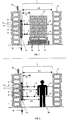
- 1 shows a device for monitoring a protection zone 1, whose width is indicated by L1.
- the protection area 1 is on one side by a sensor unit 2 and bounded on the other side by a limiting element 3.
- the sensor unit 2 consists of a housing 4 in which schematically indicated transmitter 5 and receiver 6 are arranged, wherein by the Transmitter 5 according to arrows 7 light signals emitted in the protection area become. These light signals 7 meet in the case of a free protection area. 1 to the limiting element 3, as indicated by the dashed lines 8 is, and are reflected on the limiting element 3 so or remarks that the returning light signals represented by arrows 9 received by the receivers 6. This can, like FIG. 1 represented, in particular carried out in the autocollimation process.
- the emission of of the light signals until the reception of the light signals Light transit time representative of the distance L1, i. the width of the protection area 1 is (since the determined light transit time is the time is that needs the emitted light to travel 2 x L1).
- a signal device 10 is connected, which in Form a warning light is formed and, for example, the changed Working condition of the protective device when permitting permissible Objects and / or an alarm signal when intrusion of illegal objects indicates, and in addition, the sensor unit 2 has another output 11, via a control line 12, for example, with a non-illustrated Machine control for a safeguarded by the protective device Machine 22 (Fig. 4) is connected.
- FIG. 1 an object 13 is arranged in the protected area, in the present Example of a pallet 14 with box-shaped arranged thereon Elements 15 consists.
- the object 13 is conveyed, for example, by a conveyor belt 21 (FIG. 4). moved through the protection area 1, wherein the free distance between the sensor unit 2 and the sensor unit 2 associated side edge of the object 13 is denoted by L2.
- Fig. 2 shows the device according to FIG. 1, wherein instead of the object 13 a person 16 is present in the protected area.
- the protective device according to the invention is first on the width L1 of the protection zone 1 is adjusted.
- the light signals 7 without object in the protection area 1 in the direction of the limiting element 3 emitted and after receiving the reflected light signals 9 determines the light transit time and stored in the system as the maximum time of light.
- an allowable object for example, the object 13, in a position brought into the protection area 1, the permissible position is to be recognized, i. upon entering an object 13 in the Protection zone 1 to the corresponding permissible position at a distance L2 from the sensor unit 2 should not generate a break signal and thus the alarm device 10 and the connected machine control not controlled.
- the light transit time is determined, which need the emitted light signals 7 to cover the distance L2, to be reflected on the side wall of the object 13 and then be received again by the transmitters 6.
- the determined The light runtime is considered as a further permissible light runtime, in addition to the Maximum light runtime, stored in the system.
- the other permissible light transit times for the different Transmitter / receiver pairs will also be different if this should be required by the shape of the permitted object.
- both the maximum light transit time as well as the other permissible light transit times not through a learning process learned in the system, but already predefined in this or can be entered based on calculations.
- the boundary elements 3 and the objects 13 are the predetermined Light transit times are positioned accordingly.
- the process of the invention is in this Case before triggering an alarm or stop command checked if this is shorter determined light transit time within a predetermined tolerance range or one of the other permissible light propagation times, as shown in FIG. 1 for example, corresponds to the distance L2.
- the object 13 is recognized as a permissible object and no interrupt signal is generated and thus neither an alarm signal by the alarm device 10 is still a shutdown signal via the control line 12 generated.
- the permissible light running time is, at regular intervals or continuously the respectively determined light runtime with the permissible light runtime compared.
- a criterion for generating an interrupt signal for example be checked, whether within a given time interval neither the maximum time of light nor any other permitted time of light, is determined in each case with corresponding tolerance values.
- the interrupt signal is generated and via the alarm device Alarm triggered and via the control line 12, a shutdown signal to the Machine control delivered.
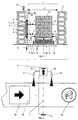
- FIGS. 3 and 4 differs from that of FIG Embodiment according to FIGS. 1 and 2 only in that in addition to the sensor unit 2 auxiliary sensors 17, 18 are provided which, as 4, with respect to the transport direction of the object 13 or behind the protection area 1 are arranged.
- the respectively before and behind the Protection area 1 arranged auxiliary sensors 17, 18 can each be redundant, i.e. be present twice or more times, where in each case the output signals the auxiliary sensors 17 arranged in front of the protected area or the auxiliary sensors 18 arranged behind the protected area AND-linked.
- the auxiliary sensors 17, 18 are via lines 19, 20 with the sensor unit 2, wherein via the lines 19, 20 start and stop signals the sensor unit can be dispensed.
- FIGS. 3 and 4 While in the embodiment according to FIGS. 1 and 2 switching the comparison values of the light propagation time from the maximum light transit time the further permissible light runtime automatically by the penetration of the Object 13 is in the protection area 1, the embodiment is according to FIGS. 3 and 4 particularly useful if, for example, due the contour of the object 13 of this switching within a maximum permissible response time is not possible.
- the switching is not by the penetration of the object 13 into the protected area 1, but initiated by a output from the auxiliary sensor 17 start signal.
- the object 13 is about to be Entering the protection area 1 of the auxiliary sensor 17, for example as a light barrier or as another suitable detection unit may be formed, detected, whereupon a corresponding start signal is discharged via the line 19 to the sensor unit 2. Because of this Start signal is used in the next scan instead of the maximum light runtime the further permissible light runtime for the comparison with the determined light transit time used, so that already at the entrance of the front Edge of the object 13 in the protection area 1, the correct allowable Light runtime is used as comparison value.
- auxiliary sensor 18 is usually very arranged closely behind the protection area 1
- the auxiliary sensors 17, 18 in different ways be used.
- the auxiliary sensors 17, 18 for the initiation of automuting i. automatic switching from the maximum light propagation time to the further permissible light transit time become.
- This switching occurs when at least one the auxiliary sensors 17, 18 recognize an allowable object, i. the exits the auxiliary sensors 17, 18 are, for example, OR-linked.
- Tv represents the total response time of the device
- n the number of light transit time measurements of a beam used for evaluation
- T m the response time or measurement time of a time of flight measurement
- T a the response time of the evaluation of the results of the time of flight measurement.
- T a represents the response time of the evaluation of the results of the time-of-flight measurements
- T aa the general response time of the evaluations
- T V1 the response time for comparison with the maximum time of light
- T V2 the response time for comparison with the remaining allowable time of light.
- auxiliary sensor 17 both the Start and the stop signal generated so that in this case on the Auxiliary sensor 18 can be omitted.
- FIGS. 1 to 4 only one-sided Protective devices show is the embodiment of FIG. 5 designed as a two-sided protective device.
- a sensor unit is in each case on both sides of the protection area 2, 2 'arranged, which may be formed substantially identical. Due to the two-sided arrangement of the sensor units 2, 2 'is ensured that upon penetration of an object 13 in the protection area 1 on both sides of the object 13 an active protective field remains. In the embodiment shown in Fig. 5 is by the light signals 7, 9 of the sensor unit 2, a left-side protective field and through the Light signals 7 ', 9' of the sensor unit 2 'receive a right-sided protective field.
- the sensor units 2, 2 ' can be connected via a simple follower connection (OSSD output) connected to each other, so that a drive the alarm device 10 and the machine control via the control line 12 is independently possible by each of the sensor units 2, 2 '.
- a simple follower connection (OSSD output) connected to each other, so that a drive the alarm device 10 and the machine control via the control line 12 is independently possible by each of the sensor units 2, 2 '.
Landscapes
- Physics & Mathematics (AREA)
- Engineering & Computer Science (AREA)
- Electromagnetism (AREA)
- General Physics & Mathematics (AREA)
- Computer Networks & Wireless Communication (AREA)
- Radar, Positioning & Navigation (AREA)
- Remote Sensing (AREA)
- Geophysics (AREA)
- General Life Sciences & Earth Sciences (AREA)
- Life Sciences & Earth Sciences (AREA)
- Geophysics And Detection Of Objects (AREA)
- Optical Radar Systems And Details Thereof (AREA)
- Burglar Alarm Systems (AREA)
Description
- Fig. 1
- eine Seitenansicht einer erfindungsgemäß ausgebildeten Vorrichtung mit einem zulässigen Objekt,
- Fig. 2
- eine erfindungsgemäß ausgebildete Vorrichtung mit einer Person im Schutzbereich,
- Fig. 3
- eine weitere Ausführungsform der Erfindung,
- Fig. 4
- eine Draufsicht auf die Ausführungsform nach Fig. 3 und
- Fig. 5
- eine weitere Ausführungsform der Erfindung.
- 1
- Schutzbereich
- 2, 2'
- Sensoreinheiten
- 3, 3'
- Begrenzungselement
- 4
- Gehäuse
- 5, 5'
- Sender
- 6, 6'
- Empfänger
- 7, 7'
- Pfeile/Lichtsignale
- 8, 8'
- gestrichelte Linie
- 9, 9'
- Pfeile/reflektierte Lichtsignale
- 10
- Alarmeinrichtung
- 11
- Ausgang
- 12
- Steuerleitung
- 13
- Objekt
- 14
- Palette
- 15
- kistenförmige Elemente
- 16
- Person
- 17
- Hilfssensor
- 18
- Hilfssensor
- 19
- Leitung
- 20
- Leitung
- 21
- Förderband
- 22
- Maschine
- 23, 23'
- Reflektoren
- L1
- Breite des Schutzbereichs
- L2, L2', L2", L2'''
- zulässige Abstände
- L 3, L4
- unzulässige Abstände
Claims (21)
- Verfahren zum Überwachen eines Schutzbereichs, bei dem zumindest ein Lichtsignal durch den Schutzbereich hindurch in Richtung eines den Schutzbereich zumindest bereichsweise begrenzenden Begrenzungselements ausgesandt wird, das Lichtsignal von dem Begrenzungselement zu einem Lichtempfänger reflektiert oder remittiert wird, die Lichtlaufzeit vom Aussenden bis zum Empfangen des Lichtsignals ermittelt wird und ein Unterbrechungssignal erzeugt wird, wenn die ermittelte Lichtlaufzeit von einer vorbestimmten Maximal-Lichtlaufzeit zumindest um einen vorgegebenen Schwellenwert abweicht,
dadurch gekennzeichnet, daß die ermittelte Lichtlaufzeit mit zumindest einer weiteren, von der Maximal-Lichtlaufzeit verschiedenen, zulässigen Lichtlaufzeit verglichen wird und kein Unterbrechungssignal erzeugt wird, wenn die ermittelte Lichtlaufzeit innerhalb eines vorgegebenen Toleranzbereichs um die zulässige Lichtlaufzeit liegt. - Verfahren nach Anspruch 1,
dadurch gekennzeichnet, daß die Lichtlaufzeit des Lichtsignals kontinuierlich oder in vorgegebenen, insbesondere periodischen Zeitabständen ermittelt wird. - Verfahren nach Anspruch 1 oder 2,
dadurch gekennzeichnet, daß die jeweils ermittelte Lichtlaufzeit automatisch mit der weiteren zulässigen Lichtlaufzeit verglichen wird, wenn eine Überschreitung des Schwellenwertes festgestellt wird. - Verfahren nach einem der vorhergehenden Ansprüche,
dadurch gekennzeichnet, daß die jeweils ermittelte Lichtlaufzeit solange mit der weiteren zulässigen Lichtlaufzeit verglichen wird, bis eine Überschreitung des Toleranzbereichs festgestellt wird. - Verfahren nach einem der vorhergehenden Ansprüche,
dadurch gekennzeichnet, daß das Unterbrechungssignal erzeugt wird, wenn innerhalb eines vorgegebenen Zeitintervalls weder das Unterschreiten des Schwellenwertes noch das Einhalten des Toleranzbereichs festgestellt wird. - Verfahren nach einem der vorhergehenden Ansprüche,
dadurch gekennzeichnet, daß der Vergleich der ermittelten Lichtlaufzeit mit der weiteren zulässigen Lichtlaufzeit durch ein externes Startsignal ausgelöst wird, insbesondere daß das Startsignal durch ein zu erkennendes Objekt erzeugt wird, unmittelbar bevor dieses in den Schutzbereich eindringt. - Verfahren nach einem der vorhergehenden Ansprüche,
dadurch gekennzeichnet, daß von dem Vergleich der ermittelten Lichtlaufzeit mit der weiteren zulässigen Lichtlaufzeit auf den Vergleich mit der Maximal-Lichtlaufzeit aufgrund eines externen Stoppsignals umgeschaltet wird, insbesondere daß das Stoppsignal durch ein zu erkennendes Objekt erzeugt wird, unmittelbar nachdem dieses den Schutzbereich verlassen hat. - Verfahren nach einem der vorhergehenden Ansprüche,
dadurch gekennzeichnet, daß das Unterbrechungssignal erzeugt wird, wenn die ermittelte Lichtlaufzeit die vorbestimmte Maximal-Lichtlaufzeit zumindest um den vorgegebenen Schwellenwert unterschreitet. - Verfahren nach einem der vorhergehenden Ansprüche,
dadurch gekennzeichnet, daß bei Erzeugen des Unterbrechungssignals eine durch den Schutzbereich gesicherte Vorrichtung abgeschaltet und/oder ein Alarmsignal erzeugt wird. - Verfahren nach einem der vorhergehenden Ansprüche,
dadurch gekennzeichnet, daß die Maximal-Lichtlaufzeit und/oder die weitere zulässige Lichtlaufzeit in einem Teach-In-Verfahren eingelernt werden. - Verfahren nach einem der vorhergehenden Ansprüche,
dadurch gekennzeichnet, daß die ermittelte Lichtlaufzeit mit mehreren weiteren zulässigen Lichtlaufzeiten verglichen wird. - Verfahren nach einem der vorhergehenden Ansprüche,
dadurch gekennzeichnet, daß mehrere, insbesondere ein Lichtgitter bildende Lichtsignale verwendet werden. - Verfahren nach einem der vorhergehenden Ansprüche,
dadurch gekennzeichnet, daß kein Unterbrechungssignal erzeugt wird, wenn zumindest für einen Teil der Lichtsignale die ermittelte Lichtlaufzeit innerhalb eines vorgegebenen Toleranzbereichs um eine jeweils zulässige Lichtlaufzeit liegt. - Verfahren nach einem der vorhergehenden Ansprüche,
dadurch gekennzeichnet, daß die Lichtsignale aus unterschiedlichen Richtungen, insbesondere aus gegenüberliegenden Richtungen durch den Schutzbereich hindurch gesandt werden. - Verfahren nach einem der vorhergehenden Ansprüche,
dadurch gekennzeichnet, daß pulsförmige Lichtsignale verwendet werden. - Vorrichtung zur Überwachung eines Schutzbereichs (1) mit zumindest einem ein Lichtsignal (7, 7') in den Schutzbereich aussenden Sender (5, 5'), einem dem Sender (5, 5') gegenüberliegenden, den Schutzbereich (1) zumindest teilweise begrenzenden Begrenzungselement (3, 3', 23, 23') zum Reflektieren oder Remittieren des ausgesandten Lichtsignals (7, 7'), zumindest einem Empfänger (6, 6') zum Empfangen des reflektierten oder remittierten Lichtsignals (9, 9') und einer Auswerteeinheit zum Ermitteln der Lichtlaufzeit zwischen Aussenden und Empfangen des Lichtsignals (7, 7', 9, 9') und zum Erzeugen eines Unterbrechungssignals, wenn die ermittelte Lichtlaufzeit von einer vorbestimmten Maximal-Lichtlaufzeit zumindest um einen vorgegebenen Schwellenwert abweicht, insbesondere zur Durchführung des Verfahrens nach einem der vorhergehenden Ansprüche,
dadurch gekennzeichnet, daß die Auswerteeinheit zum Vergleichen der ermittelten Lichtlaufzeit mit zumindest einer weiteren, von der Maximal-Lichtlaufzeit verschiedenen, zulässigen Lichtlaufzeit ausgebildet ist und daß die Auswerteeinheit kein Unterbrechungssignal erzeugt, wenn die ermittelte Lichtlaufzeit innerhalb eines vorgegebenen Toleranzbereichs um die zulässige Lichtlaufzeit liegt. - Vorrichtung nach Anspruch 16,
dadurch gekennzeichnet, daß mehrere Sender (5, 5') und Empfänger (6, 6') vorgesehen sind, die zusammen mit einem oder mehreren Begrenzungselementen (3, 3', 23, 23') ein Lichtgitter bilden. - Vorrichtung nach Anspruch 16 oder 17,
dadurch gekennzeichnet, daß die Sender (5, 5') und Empfänger (6, 6') sowie die Begrenzungselemente (3, 23) im wesentlichen in einer Ebene angeordnet sind. - Vorrichtung nach einem der Ansprüche 16 bis 18,
dadurch gekennzeichnet, daß jeweils einander zugeordnete Sender (5, 5') und Empfänger (6, 6') auf derselben Seite des Schutzbereichs (1) und das zugeordnete Begrenzungselement (3, 3', 23, 23') auf der gegenüberliegenden Seite der Schutzbereichs (1) angeordnet sind. - Vorrichtung nach einem der Ansprüche 16 bis 19,
dadurch gekennzeichnet, daß das Begrenzungselement (3, 3') als Reflektor (23, 23') ausgebildet ist. - Vorrichtung nach einem der Ansprüche 16 bis 20,
dadurch gekennzeichnet, daß auf beiden Seiten des Schutzbereichs (1) sowohl Sender (5, 5') als auch Empfänger (6, 6') als auch Begrenzungselemente (3, 3', 23, 23') angeordnet sind, insbesondere daß die auf beiden Seiten des Schutzbereichs (1) angeordneten Sender (5, 5'), Empfänger (6, 6') und Begrenzungselemente (3, 3', 23, 23') im wesentlichen baugleich ausgebildet sind.
Applications Claiming Priority (2)
| Application Number | Priority Date | Filing Date | Title |
|---|---|---|---|
| DE19946476 | 1999-09-28 | ||
| DE19946476A DE19946476A1 (de) | 1999-09-28 | 1999-09-28 | Verfahren und Vorrichtung zum Überwachen eines Schutzbereichs |
Publications (3)
| Publication Number | Publication Date |
|---|---|
| EP1089030A2 EP1089030A2 (de) | 2001-04-04 |
| EP1089030A3 EP1089030A3 (de) | 2004-08-11 |
| EP1089030B1 true EP1089030B1 (de) | 2005-12-28 |
Family
ID=7923590
Family Applications (1)
| Application Number | Title | Priority Date | Filing Date |
|---|---|---|---|
| EP00118407A Expired - Lifetime EP1089030B1 (de) | 1999-09-28 | 2000-08-24 | Verfahren und Vorrichtung zum Überwachen eines Schutzbereichs |
Country Status (3)
| Country | Link |
|---|---|
| EP (1) | EP1089030B1 (de) |
| AT (1) | ATE314607T1 (de) |
| DE (2) | DE19946476A1 (de) |
Cited By (8)
| Publication number | Priority date | Publication date | Assignee | Title |
|---|---|---|---|---|
| DE202009003002U1 (de) | 2009-03-04 | 2010-07-22 | Sick Ag | Optoelektronische Sensorenanordnung mit mehreren Lichtempfangspfaden |
| DE202013103234U1 (de) | 2013-07-18 | 2014-10-21 | Sick Ag | Mikrowellenschranke zum Überwachen eines Überwachungsbereichs |
| DE102013107696A1 (de) | 2013-07-18 | 2015-01-22 | Sick Ag | Mikrowellenschranke und Verfahren zum Überwachen eines Überwachungsbereichs |
| DE102014110203B3 (de) * | 2014-07-21 | 2015-08-06 | Sick Ag | Entfernungsmessender Sensor zur Erfassung und Abstandsbestimmung von Objekten |
| DE202014103348U1 (de) | 2014-07-21 | 2015-10-22 | Sick Ag | Entfernungsmessender Sensor zur Erfassung und Abstandsbestimmung von Objekten |
| DE202020101055U1 (de) | 2020-02-26 | 2021-05-27 | Sick Ag | Vorrichtung zum Überwachen eines Schutzbereichs |
| DE102020105037A1 (de) | 2020-02-26 | 2021-08-26 | Sick Ag | Vorrichtung zum Überwachen eines Schutzbereichs |
| EP2306063B2 (de) † | 2009-10-02 | 2022-08-10 | Leuze electronic GmbH + Co. KG | Sicherheitssensor |
Families Citing this family (28)
| Publication number | Priority date | Publication date | Assignee | Title |
|---|---|---|---|---|
| DE10122402B4 (de) * | 2001-05-09 | 2005-10-27 | Rational Ag | Verfahren zur Sicherung eines Gargeräts und dieses durchführende Gargerät |
| DE10163534A1 (de) | 2001-12-21 | 2003-07-10 | Siemens Ag | Vorrichtung zur Überwachung von Raumbereichen |
| DE10216122A1 (de) * | 2002-04-12 | 2003-10-30 | Sick Ag | Objekterfassung |
| DE10233258B4 (de) * | 2002-07-23 | 2006-07-13 | Leuze Lumiflex Gmbh + Co. Kg | Lichtgitter |
| DE10329881A1 (de) | 2003-07-02 | 2005-01-20 | Sick Ag | Lichtgitter |
| DE20310903U1 (de) * | 2003-07-16 | 2003-09-25 | Leuze electronic GmbH + Co. KG, 73277 Owen | Optoelektronische Vorrichtung |
| JP4009862B2 (ja) * | 2003-09-30 | 2007-11-21 | オムロン株式会社 | 多光軸光電センサ |
| DE10359782A1 (de) * | 2003-12-19 | 2005-07-21 | Sick Ag | Verfahren und Vorrichtung zur Flächenüberwachung |
| DE10360789B4 (de) | 2003-12-23 | 2007-03-15 | Leuze Lumiflex Gmbh + Co. Kg | Vorrichtung zur Überwachung eines Erfassungsbereichs an einem Arbeitsmittel |
| GB0416583D0 (en) * | 2004-07-23 | 2004-08-25 | Rwl Consultants Ltd | Access monitoring apparatus |
| DE102004049482A1 (de) * | 2004-10-11 | 2006-04-13 | Sick Ag | Vorrichtung zur Überwachung von bewegten Objekten |
| ES2289633T3 (es) | 2004-10-11 | 2008-02-01 | Sick Ag | Dispositivo y procedimiento para la vigilancia de objetos en movimiento. |
| DE102006002356B4 (de) * | 2005-02-21 | 2021-05-06 | Heidelberger Druckmaschinen Ag | Verfahren und Vorrichtung zur Absicherung von Gefahrbereichen in Bogendruckmaschinen |
| DE102005030829C5 (de) * | 2005-07-01 | 2016-05-19 | Sick Ag | Verfahren zum Betrieb eines Lichtgitters und Lichtgitter |
| DE102005038019A1 (de) | 2005-08-09 | 2007-02-15 | Cedes Ag | Sensorvorrichtung zur Detektion eines Überhangs an der Beladung einer Trägereinrichtung |
| DE102007033766B4 (de) * | 2007-07-18 | 2009-11-26 | Leuze Lumiflex Gmbh + Co. Kg | Lichtgitter |
| ITTO20070691A1 (it) * | 2007-10-01 | 2009-04-02 | Reer Spa | "barriera fotoelettrica" |
| DE102008033195B4 (de) * | 2008-07-15 | 2012-11-22 | Maschinenfabrik Berthold Hermle Ag | Bearbeitungszentrum mit einer Werkstücktransporteinrichtung und einem Werkstückbereitstellungsplatz mit opto-elektronischer Schutzeinrichtung |
| DE502008002633D1 (de) * | 2008-10-22 | 2011-03-31 | Sick Ag | Sicherheitslichtgitter und entsprechendes Verfahren zur Überwachung eines Schutzbereichs |
| EP2192423B1 (de) | 2008-11-27 | 2017-04-19 | Pepperl + Fuchs GmbH | Mehrstrahliges Reflexionslichtgitter und Verfahren zum Betreiben eines mehrstrahligen Reflexionslichtgitters |
| DE202008016093U1 (de) * | 2008-12-05 | 2010-04-15 | Sick Ag | Überwachungssensor |
| DE202010005042U1 (de) * | 2010-04-15 | 2011-08-12 | Sick Ag | Optoelektronische Vorrichtung |
| DK2506034T3 (da) | 2011-04-01 | 2013-09-02 | Cedes Ag | Sensorindretning, sikkerhedsindretning, dør og fremgangsmåde til kontrol af bevægelsen |
| EP3422053B1 (de) * | 2017-06-28 | 2021-05-19 | Datalogic IP Tech S.r.l. | Sicherheitssystem |
| DE102019116806B4 (de) * | 2019-06-21 | 2023-07-20 | Wilhelm B a h m ü l l e r Maschinenbau Präzisionswerkzeuge GmbH | Vorrichtung und Verfahren zur Überwachung eines Gefahrenbereichs |
| DE202021104977U1 (de) | 2021-09-15 | 2023-01-12 | Leuze Electronic Gmbh + Co. Kg | Überwachungseinrichtung |
| DE202022103201U1 (de) | 2022-06-07 | 2023-10-17 | Leuze Electronic Gmbh + Co. Kg | Überwachungseinrichtung |
| DE102023115311B4 (de) * | 2023-06-13 | 2025-07-03 | Sick Ag | Zugangsabsicherungssystem |
Family Cites Families (6)
| Publication number | Priority date | Publication date | Assignee | Title |
|---|---|---|---|---|
| US3727207A (en) * | 1970-06-24 | 1973-04-10 | Systron Donner Corp | Intrusion detector |
| DE4119797C2 (de) * | 1991-06-15 | 1994-02-24 | Leuze Electronic Gmbh & Co | Einen Sender, einen Empfänger und eine Schaltungsanordnung zur Signalauswertung aufweisende Überwachungseinrichtung |
| DE4422497C2 (de) * | 1994-06-28 | 1996-06-05 | Leuze Electronic Gmbh & Co | Vorrichtung und Verfahren zum optoelektronischen Erfassen von Gegenständen |
| DE19601661C1 (de) * | 1996-01-18 | 1997-07-17 | Leuze Electronic Gmbh & Co | Verfahren zum Erfassen von Objekten in einem Überwachungsbereich |
| DE19621120C1 (de) * | 1996-05-24 | 1997-05-07 | Leuze Electronic Gmbh & Co | Optoelektronische Vorrichtung |
| JP2944599B2 (ja) * | 1998-01-07 | 1999-09-06 | 株式会社ツーデン | 移動式ドアの安全装置並びに安全兼起動装置 |
-
1999
- 1999-09-28 DE DE19946476A patent/DE19946476A1/de not_active Withdrawn
-
2000
- 2000-08-24 AT AT00118407T patent/ATE314607T1/de not_active IP Right Cessation
- 2000-08-24 DE DE50011954T patent/DE50011954D1/de not_active Expired - Lifetime
- 2000-08-24 EP EP00118407A patent/EP1089030B1/de not_active Expired - Lifetime
Cited By (11)
| Publication number | Priority date | Publication date | Assignee | Title |
|---|---|---|---|---|
| DE202009003002U1 (de) | 2009-03-04 | 2010-07-22 | Sick Ag | Optoelektronische Sensorenanordnung mit mehreren Lichtempfangspfaden |
| EP2306063B2 (de) † | 2009-10-02 | 2022-08-10 | Leuze electronic GmbH + Co. KG | Sicherheitssensor |
| DE202013103234U1 (de) | 2013-07-18 | 2014-10-21 | Sick Ag | Mikrowellenschranke zum Überwachen eines Überwachungsbereichs |
| DE102013107696A1 (de) | 2013-07-18 | 2015-01-22 | Sick Ag | Mikrowellenschranke und Verfahren zum Überwachen eines Überwachungsbereichs |
| DE102013107696B4 (de) * | 2013-07-18 | 2020-03-05 | Sick Ag | Mikrowellenschranke |
| DE102014110203B3 (de) * | 2014-07-21 | 2015-08-06 | Sick Ag | Entfernungsmessender Sensor zur Erfassung und Abstandsbestimmung von Objekten |
| DE202014103348U1 (de) | 2014-07-21 | 2015-10-22 | Sick Ag | Entfernungsmessender Sensor zur Erfassung und Abstandsbestimmung von Objekten |
| EP2977786A1 (de) | 2014-07-21 | 2016-01-27 | Sick Ag | Entfernungsmessender sensor zur erfassung und abstandsbestimmungen von objekten |
| DE202020101055U1 (de) | 2020-02-26 | 2021-05-27 | Sick Ag | Vorrichtung zum Überwachen eines Schutzbereichs |
| DE102020105037A1 (de) | 2020-02-26 | 2021-08-26 | Sick Ag | Vorrichtung zum Überwachen eines Schutzbereichs |
| EP3872526A1 (de) | 2020-02-26 | 2021-09-01 | Sick Ag | Vorrichtung zum überwachen eines schutzbereichs |
Also Published As
| Publication number | Publication date |
|---|---|
| DE50011954D1 (de) | 2006-02-02 |
| DE19946476A1 (de) | 2001-03-29 |
| EP1089030A3 (de) | 2004-08-11 |
| ATE314607T1 (de) | 2006-01-15 |
| EP1089030A2 (de) | 2001-04-04 |
Similar Documents
| Publication | Publication Date | Title |
|---|---|---|
| EP1089030B1 (de) | Verfahren und Vorrichtung zum Überwachen eines Schutzbereichs | |
| EP2180348B1 (de) | Sicherheitslichtgitter und entsprechendes Verfahren zur Überwachung eines Schutzbereichs | |
| EP1544643B1 (de) | Verfahren und Vorrichtung zur Flächenüberwachung mit mehreren nebeneinander angeordneten Lichtsendern | |
| EP2017524B1 (de) | Lichtgitter | |
| EP2071363B1 (de) | Lichtgitter und Verfahren zu dessen Betrieb | |
| DE19828000C2 (de) | Verfahren zur optoelektronischen Überwachung eines Schutzbereichs | |
| EP2306063B2 (de) | Sicherheitssensor | |
| CH659521A5 (de) | Fotoelektrische einrichtung zum abtasten von gegenstaenden. | |
| EP2990836B1 (de) | Vorrichtung zur Überwachung einer Maschinenbewegung und Verfahren zum Überwachen einer Maschinenbewegung | |
| EP2362242B1 (de) | Optoelektronischer Sensor | |
| DE60208487T2 (de) | Photoelektrische Sicherheitsgitter mit Muting-Funktion | |
| EP3415804B1 (de) | Sicherheitsvorrichtung | |
| EP0280137B1 (de) | Sicherheitsvorrichtung für System mit fahrerlosen Fahrzeugen | |
| EP4151899A1 (de) | Überwachungseinrichtung | |
| EP1288559B1 (de) | Optoelektronische Überwachungseinrichtung | |
| DE2941119C2 (de) | ||
| DE202019103376U1 (de) | Vorrichtung | |
| DE102017119283B4 (de) | Sensorsystem | |
| DE3728354C2 (de) | ||
| DE19537051C1 (de) | Optoelektronische Sensoranordnung | |
| EP1780559B1 (de) | Optischer Sensor | |
| EP2722692B1 (de) | Sensor | |
| EP3872526B1 (de) | Vorrichtung zum überwachen eines schutzbereichs | |
| EP1416457B1 (de) | Optische Überwachungsvorrichtung | |
| EP3910229B1 (de) | Überwachungseinrichtung |
Legal Events
| Date | Code | Title | Description |
|---|---|---|---|
| PUAI | Public reference made under article 153(3) epc to a published international application that has entered the european phase |
Free format text: ORIGINAL CODE: 0009012 |
|
| AK | Designated contracting states |
Kind code of ref document: A2 Designated state(s): AT BE CH CY DE DK ES FI FR GB GR IE IT LI LU MC NL PT SE |
|
| AX | Request for extension of the european patent |
Free format text: AL;LT;LV;MK;RO;SI |
|
| PUAL | Search report despatched |
Free format text: ORIGINAL CODE: 0009013 |
|
| AK | Designated contracting states |
Kind code of ref document: A3 Designated state(s): AT BE CH CY DE DK ES FI FR GB GR IE IT LI LU MC NL PT SE |
|
| AX | Request for extension of the european patent |
Extension state: AL LT LV MK RO SI |
|
| RIC1 | Information provided on ipc code assigned before grant |
Ipc: 7F 16P 3/14 A Ipc: 7G 01S 17/10 B Ipc: 7G 01V 8/14 B Ipc: 7G 01S 17/02 B |
|
| 17P | Request for examination filed |
Effective date: 20041007 |
|
| AKX | Designation fees paid |
Designated state(s): AT BE CH CY DE DK ES FI FR GB GR IE IT LI LU MC NL PT SE |
|
| GRAP | Despatch of communication of intention to grant a patent |
Free format text: ORIGINAL CODE: EPIDOSNIGR1 |
|
| GRAS | Grant fee paid |
Free format text: ORIGINAL CODE: EPIDOSNIGR3 |
|
| GRAA | (expected) grant |
Free format text: ORIGINAL CODE: 0009210 |
|
| AK | Designated contracting states |
Kind code of ref document: B1 Designated state(s): AT BE CH CY DE DK ES FI FR GB GR IE IT LI LU MC NL PT SE |
|
| PG25 | Lapsed in a contracting state [announced via postgrant information from national office to epo] |
Ref country code: IE Free format text: LAPSE BECAUSE OF FAILURE TO SUBMIT A TRANSLATION OF THE DESCRIPTION OR TO PAY THE FEE WITHIN THE PRESCRIBED TIME-LIMIT Effective date: 20051228 Ref country code: GB Free format text: LAPSE BECAUSE OF FAILURE TO SUBMIT A TRANSLATION OF THE DESCRIPTION OR TO PAY THE FEE WITHIN THE PRESCRIBED TIME-LIMIT Effective date: 20051228 Ref country code: FI Free format text: LAPSE BECAUSE OF FAILURE TO SUBMIT A TRANSLATION OF THE DESCRIPTION OR TO PAY THE FEE WITHIN THE PRESCRIBED TIME-LIMIT Effective date: 20051228 Ref country code: NL Free format text: LAPSE BECAUSE OF FAILURE TO SUBMIT A TRANSLATION OF THE DESCRIPTION OR TO PAY THE FEE WITHIN THE PRESCRIBED TIME-LIMIT Effective date: 20051228 |
|
| REG | Reference to a national code |
Ref country code: GB Ref legal event code: FG4D Free format text: NOT ENGLISH |
|
| REG | Reference to a national code |
Ref country code: CH Ref legal event code: EP |
|
| REG | Reference to a national code |
Ref country code: IE Ref legal event code: FG4D Free format text: LANGUAGE OF EP DOCUMENT: GERMAN |
|
| REF | Corresponds to: |
Ref document number: 50011954 Country of ref document: DE Date of ref document: 20060202 Kind code of ref document: P |
|
| PG25 | Lapsed in a contracting state [announced via postgrant information from national office to epo] |
Ref country code: GR Free format text: LAPSE BECAUSE OF FAILURE TO SUBMIT A TRANSLATION OF THE DESCRIPTION OR TO PAY THE FEE WITHIN THE PRESCRIBED TIME-LIMIT Effective date: 20060328 Ref country code: SE Free format text: LAPSE BECAUSE OF FAILURE TO SUBMIT A TRANSLATION OF THE DESCRIPTION OR TO PAY THE FEE WITHIN THE PRESCRIBED TIME-LIMIT Effective date: 20060328 Ref country code: DK Free format text: LAPSE BECAUSE OF FAILURE TO SUBMIT A TRANSLATION OF THE DESCRIPTION OR TO PAY THE FEE WITHIN THE PRESCRIBED TIME-LIMIT Effective date: 20060328 |
|
| PG25 | Lapsed in a contracting state [announced via postgrant information from national office to epo] |
Ref country code: ES Free format text: LAPSE BECAUSE OF FAILURE TO SUBMIT A TRANSLATION OF THE DESCRIPTION OR TO PAY THE FEE WITHIN THE PRESCRIBED TIME-LIMIT Effective date: 20060408 |
|
| PG25 | Lapsed in a contracting state [announced via postgrant information from national office to epo] |
Ref country code: PT Free format text: LAPSE BECAUSE OF FAILURE TO SUBMIT A TRANSLATION OF THE DESCRIPTION OR TO PAY THE FEE WITHIN THE PRESCRIBED TIME-LIMIT Effective date: 20060529 |
|
| NLV1 | Nl: lapsed or annulled due to failure to fulfill the requirements of art. 29p and 29m of the patents act | ||
| GBV | Gb: ep patent (uk) treated as always having been void in accordance with gb section 77(7)/1977 [no translation filed] |
Effective date: 20051228 |
|
| REG | Reference to a national code |
Ref country code: IE Ref legal event code: FD4D |
|
| PG25 | Lapsed in a contracting state [announced via postgrant information from national office to epo] |
Ref country code: BE Free format text: LAPSE BECAUSE OF NON-PAYMENT OF DUE FEES Effective date: 20060831 Ref country code: CH Free format text: LAPSE BECAUSE OF NON-PAYMENT OF DUE FEES Effective date: 20060831 Ref country code: LI Free format text: LAPSE BECAUSE OF NON-PAYMENT OF DUE FEES Effective date: 20060831 Ref country code: MC Free format text: LAPSE BECAUSE OF NON-PAYMENT OF DUE FEES Effective date: 20060831 |
|
| ET | Fr: translation filed | ||
| PLBE | No opposition filed within time limit |
Free format text: ORIGINAL CODE: 0009261 |
|
| STAA | Information on the status of an ep patent application or granted ep patent |
Free format text: STATUS: NO OPPOSITION FILED WITHIN TIME LIMIT |
|
| 26N | No opposition filed |
Effective date: 20060929 |
|
| REG | Reference to a national code |
Ref country code: CH Ref legal event code: PL |
|
| PG25 | Lapsed in a contracting state [announced via postgrant information from national office to epo] |
Ref country code: AT Free format text: LAPSE BECAUSE OF NON-PAYMENT OF DUE FEES Effective date: 20060824 |
|
| BERE | Be: lapsed |
Owner name: SICK A.G. Effective date: 20060831 |
|
| PG25 | Lapsed in a contracting state [announced via postgrant information from national office to epo] |
Ref country code: LU Free format text: LAPSE BECAUSE OF NON-PAYMENT OF DUE FEES Effective date: 20060824 |
|
| PG25 | Lapsed in a contracting state [announced via postgrant information from national office to epo] |
Ref country code: CY Free format text: LAPSE BECAUSE OF FAILURE TO SUBMIT A TRANSLATION OF THE DESCRIPTION OR TO PAY THE FEE WITHIN THE PRESCRIBED TIME-LIMIT Effective date: 20051228 |
|
| PGFP | Annual fee paid to national office [announced via postgrant information from national office to epo] |
Ref country code: FR Payment date: 20130820 Year of fee payment: 14 |
|
| REG | Reference to a national code |
Ref country code: FR Ref legal event code: ST Effective date: 20150430 |
|
| PG25 | Lapsed in a contracting state [announced via postgrant information from national office to epo] |
Ref country code: FR Free format text: LAPSE BECAUSE OF NON-PAYMENT OF DUE FEES Effective date: 20140901 |
|
| PGFP | Annual fee paid to national office [announced via postgrant information from national office to epo] |
Ref country code: IT Payment date: 20170824 Year of fee payment: 18 |
|
| PG25 | Lapsed in a contracting state [announced via postgrant information from national office to epo] |
Ref country code: IT Free format text: LAPSE BECAUSE OF NON-PAYMENT OF DUE FEES Effective date: 20180824 |
|
| PGFP | Annual fee paid to national office [announced via postgrant information from national office to epo] |
Ref country code: DE Payment date: 20190822 Year of fee payment: 20 |
|
| REG | Reference to a national code |
Ref country code: DE Ref legal event code: R071 Ref document number: 50011954 Country of ref document: DE |