EP2498694B1 - Medical device, apparatus, and surgical method - Google Patents
Medical device, apparatus, and surgical method Download PDFInfo
- Publication number
- EP2498694B1 EP2498694B1 EP10778830.9A EP10778830A EP2498694B1 EP 2498694 B1 EP2498694 B1 EP 2498694B1 EP 10778830 A EP10778830 A EP 10778830A EP 2498694 B1 EP2498694 B1 EP 2498694B1
- Authority
- EP
- European Patent Office
- Prior art keywords
- anchor device
- pedicle
- liquefiable
- longitudinal bore
- distal
- Prior art date
- Legal status (The legal status is an assumption and is not a legal conclusion. Google has not performed a legal analysis and makes no representation as to the accuracy of the status listed.)
- Not-in-force
Links
- 238000000034 method Methods 0.000 title description 24
- 239000000463 material Substances 0.000 claims description 88
- 230000000087 stabilizing effect Effects 0.000 claims description 10
- 238000003780 insertion Methods 0.000 claims description 8
- 230000037431 insertion Effects 0.000 claims description 8
- 241001465754 Metazoa Species 0.000 claims description 3
- 238000004873 anchoring Methods 0.000 description 49
- 210000000988 bone and bone Anatomy 0.000 description 38
- 210000001519 tissue Anatomy 0.000 description 24
- 229920000642 polymer Polymers 0.000 description 18
- 239000003814 drug Substances 0.000 description 15
- 229940079593 drug Drugs 0.000 description 15
- 229920001169 thermoplastic Polymers 0.000 description 14
- 230000003416 augmentation Effects 0.000 description 13
- 239000007943 implant Substances 0.000 description 13
- 239000004568 cement Substances 0.000 description 12
- 230000000694 effects Effects 0.000 description 12
- 239000012815 thermoplastic material Substances 0.000 description 11
- 239000011396 hydraulic cement Substances 0.000 description 10
- 239000000126 substance Substances 0.000 description 10
- 239000004416 thermosoftening plastic Substances 0.000 description 10
- 239000003102 growth factor Substances 0.000 description 8
- 230000035876 healing Effects 0.000 description 8
- 238000002513 implantation Methods 0.000 description 8
- 230000008569 process Effects 0.000 description 8
- QORWJWZARLRLPR-UHFFFAOYSA-H tricalcium bis(phosphate) Chemical compound [Ca+2].[Ca+2].[Ca+2].[O-]P([O-])([O-])=O.[O-]P([O-])([O-])=O QORWJWZARLRLPR-UHFFFAOYSA-H 0.000 description 8
- 239000000945 filler Substances 0.000 description 7
- -1 biphosphonates) Chemical class 0.000 description 6
- 230000004069 differentiation Effects 0.000 description 6
- 230000012010 growth Effects 0.000 description 6
- 239000000203 mixture Substances 0.000 description 6
- 238000003825 pressing Methods 0.000 description 6
- 239000001506 calcium phosphate Substances 0.000 description 5
- 235000011010 calcium phosphates Nutrition 0.000 description 5
- 230000008878 coupling Effects 0.000 description 5
- 238000010168 coupling process Methods 0.000 description 5
- 238000005859 coupling reaction Methods 0.000 description 5
- 229920000747 poly(lactic acid) Polymers 0.000 description 5
- 230000001737 promoting effect Effects 0.000 description 5
- 239000010936 titanium Substances 0.000 description 5
- VTYYLEPIZMXCLO-UHFFFAOYSA-L Calcium carbonate Chemical compound [Ca+2].[O-]C([O-])=O VTYYLEPIZMXCLO-UHFFFAOYSA-L 0.000 description 4
- 102000010780 Platelet-Derived Growth Factor Human genes 0.000 description 4
- 108010038512 Platelet-Derived Growth Factor Proteins 0.000 description 4
- 238000013459 approach Methods 0.000 description 4
- 229910000389 calcium phosphate Inorganic materials 0.000 description 4
- 150000001875 compounds Chemical class 0.000 description 4
- 230000001054 cortical effect Effects 0.000 description 4
- 238000009826 distribution Methods 0.000 description 4
- 230000005670 electromagnetic radiation Effects 0.000 description 4
- 238000011065 in-situ storage Methods 0.000 description 4
- NOESYZHRGYRDHS-UHFFFAOYSA-N insulin Chemical compound N1C(=O)C(NC(=O)C(CCC(N)=O)NC(=O)C(CCC(O)=O)NC(=O)C(C(C)C)NC(=O)C(NC(=O)CN)C(C)CC)CSSCC(C(NC(CO)C(=O)NC(CC(C)C)C(=O)NC(CC=2C=CC(O)=CC=2)C(=O)NC(CCC(N)=O)C(=O)NC(CC(C)C)C(=O)NC(CCC(O)=O)C(=O)NC(CC(N)=O)C(=O)NC(CC=2C=CC(O)=CC=2)C(=O)NC(CSSCC(NC(=O)C(C(C)C)NC(=O)C(CC(C)C)NC(=O)C(CC=2C=CC(O)=CC=2)NC(=O)C(CC(C)C)NC(=O)C(C)NC(=O)C(CCC(O)=O)NC(=O)C(C(C)C)NC(=O)C(CC(C)C)NC(=O)C(CC=2NC=NC=2)NC(=O)C(CO)NC(=O)CNC2=O)C(=O)NCC(=O)NC(CCC(O)=O)C(=O)NC(CCCNC(N)=N)C(=O)NCC(=O)NC(CC=3C=CC=CC=3)C(=O)NC(CC=3C=CC=CC=3)C(=O)NC(CC=3C=CC(O)=CC=3)C(=O)NC(C(C)O)C(=O)N3C(CCC3)C(=O)NC(CCCCN)C(=O)NC(C)C(O)=O)C(=O)NC(CC(N)=O)C(O)=O)=O)NC(=O)C(C(C)CC)NC(=O)C(CO)NC(=O)C(C(C)O)NC(=O)C1CSSCC2NC(=O)C(CC(C)C)NC(=O)C(NC(=O)C(CCC(N)=O)NC(=O)C(CC(N)=O)NC(=O)C(NC(=O)C(N)CC=1C=CC=CC=1)C(C)C)CC1=CN=CN1 NOESYZHRGYRDHS-UHFFFAOYSA-N 0.000 description 4
- 229920006324 polyoxymethylene Polymers 0.000 description 4
- 230000008929 regeneration Effects 0.000 description 4
- 238000011069 regeneration method Methods 0.000 description 4
- 238000010008 shearing Methods 0.000 description 4
- 238000007711 solidification Methods 0.000 description 4
- 238000001356 surgical procedure Methods 0.000 description 4
- 206010017076 Fracture Diseases 0.000 description 3
- 239000004696 Poly ether ether ketone Substances 0.000 description 3
- 230000008901 benefit Effects 0.000 description 3
- JUPQTSLXMOCDHR-UHFFFAOYSA-N benzene-1,4-diol;bis(4-fluorophenyl)methanone Chemical compound OC1=CC=C(O)C=C1.C1=CC(F)=CC=C1C(=O)C1=CC=C(F)C=C1 JUPQTSLXMOCDHR-UHFFFAOYSA-N 0.000 description 3
- 229920006237 degradable polymer Polymers 0.000 description 3
- 238000002474 experimental method Methods 0.000 description 3
- 150000004676 glycans Chemical class 0.000 description 3
- 239000000017 hydrogel Substances 0.000 description 3
- 229910052588 hydroxylapatite Inorganic materials 0.000 description 3
- 230000006872 improvement Effects 0.000 description 3
- 239000007788 liquid Substances 0.000 description 3
- 239000011159 matrix material Substances 0.000 description 3
- 230000010355 oscillation Effects 0.000 description 3
- XYJRXVWERLGGKC-UHFFFAOYSA-D pentacalcium;hydroxide;triphosphate Chemical compound [OH-].[Ca+2].[Ca+2].[Ca+2].[Ca+2].[Ca+2].[O-]P([O-])([O-])=O.[O-]P([O-])([O-])=O.[O-]P([O-])([O-])=O XYJRXVWERLGGKC-UHFFFAOYSA-D 0.000 description 3
- 229920003229 poly(methyl methacrylate) Polymers 0.000 description 3
- 229920002463 poly(p-dioxanone) polymer Polymers 0.000 description 3
- 229920002492 poly(sulfone) Polymers 0.000 description 3
- 229920001610 polycaprolactone Polymers 0.000 description 3
- 239000000622 polydioxanone Substances 0.000 description 3
- 229920002530 polyetherether ketone Polymers 0.000 description 3
- 239000002861 polymer material Substances 0.000 description 3
- 239000004926 polymethyl methacrylate Substances 0.000 description 3
- 229920001282 polysaccharide Polymers 0.000 description 3
- 239000005017 polysaccharide Substances 0.000 description 3
- 239000011148 porous material Substances 0.000 description 3
- 239000001488 sodium phosphate Substances 0.000 description 3
- 235000011008 sodium phosphates Nutrition 0.000 description 3
- 230000006641 stabilisation Effects 0.000 description 3
- 238000011105 stabilization Methods 0.000 description 3
- RYFMWSXOAZQYPI-UHFFFAOYSA-K trisodium phosphate Chemical class [Na+].[Na+].[Na+].[O-]P([O-])([O-])=O RYFMWSXOAZQYPI-UHFFFAOYSA-K 0.000 description 3
- XLYOFNOQVPJJNP-UHFFFAOYSA-N water Substances O XLYOFNOQVPJJNP-UHFFFAOYSA-N 0.000 description 3
- 101150061927 BMP2 gene Proteins 0.000 description 2
- AEMRFAOFKBGASW-UHFFFAOYSA-N Glycolic acid Chemical compound OCC(O)=O AEMRFAOFKBGASW-UHFFFAOYSA-N 0.000 description 2
- 101150088952 IGF1 gene Proteins 0.000 description 2
- 206010061218 Inflammation Diseases 0.000 description 2
- 102000004877 Insulin Human genes 0.000 description 2
- 108090001061 Insulin Proteins 0.000 description 2
- JVTAAEKCZFNVCJ-REOHCLBHSA-N L-lactic acid Chemical compound C[C@H](O)C(O)=O JVTAAEKCZFNVCJ-REOHCLBHSA-N 0.000 description 2
- 101100175316 Mus musculus Gdf5 gene Proteins 0.000 description 2
- 229920002292 Nylon 6 Polymers 0.000 description 2
- 229920002302 Nylon 6,6 Polymers 0.000 description 2
- 229920000954 Polyglycolide Polymers 0.000 description 2
- 239000004743 Polypropylene Substances 0.000 description 2
- 229910001069 Ti alloy Inorganic materials 0.000 description 2
- RTAQQCXQSZGOHL-UHFFFAOYSA-N Titanium Chemical compound [Ti] RTAQQCXQSZGOHL-UHFFFAOYSA-N 0.000 description 2
- 230000002411 adverse Effects 0.000 description 2
- 239000003242 anti bacterial agent Substances 0.000 description 2
- 230000003190 augmentative effect Effects 0.000 description 2
- 239000005312 bioglass Substances 0.000 description 2
- 239000012620 biological material Substances 0.000 description 2
- 239000002639 bone cement Substances 0.000 description 2
- 230000008468 bone growth Effects 0.000 description 2
- 239000000872 buffer Substances 0.000 description 2
- 235000010216 calcium carbonate Nutrition 0.000 description 2
- 239000002131 composite material Substances 0.000 description 2
- 229920001577 copolymer Polymers 0.000 description 2
- 238000005520 cutting process Methods 0.000 description 2
- 238000005553 drilling Methods 0.000 description 2
- 230000004054 inflammatory process Effects 0.000 description 2
- 239000003112 inhibitor Substances 0.000 description 2
- 229940125396 insulin Drugs 0.000 description 2
- JVTAAEKCZFNVCJ-UHFFFAOYSA-N lactic acid Chemical compound CC(O)C(O)=O JVTAAEKCZFNVCJ-UHFFFAOYSA-N 0.000 description 2
- 238000002844 melting Methods 0.000 description 2
- 230000008018 melting Effects 0.000 description 2
- 229910052751 metal Inorganic materials 0.000 description 2
- 239000002184 metal Substances 0.000 description 2
- 230000000921 morphogenic effect Effects 0.000 description 2
- 238000010883 osseointegration Methods 0.000 description 2
- 229920001432 poly(L-lactide) Polymers 0.000 description 2
- 239000005014 poly(hydroxyalkanoate) Substances 0.000 description 2
- 229920000515 polycarbonate Polymers 0.000 description 2
- 239000004417 polycarbonate Substances 0.000 description 2
- 229920000728 polyester Polymers 0.000 description 2
- 229920000903 polyhydroxyalkanoate Polymers 0.000 description 2
- 229920001155 polypropylene Polymers 0.000 description 2
- 239000004814 polyurethane Substances 0.000 description 2
- 239000000843 powder Substances 0.000 description 2
- 102000004169 proteins and genes Human genes 0.000 description 2
- 108090000623 proteins and genes Proteins 0.000 description 2
- 230000005855 radiation Effects 0.000 description 2
- 150000003384 small molecules Chemical class 0.000 description 2
- 239000002904 solvent Substances 0.000 description 2
- 230000001225 therapeutic effect Effects 0.000 description 2
- 150000003568 thioethers Chemical class 0.000 description 2
- 229910052719 titanium Inorganic materials 0.000 description 2
- 235000019731 tricalcium phosphate Nutrition 0.000 description 2
- 210000000689 upper leg Anatomy 0.000 description 2
- NSMXQKNUPPXBRG-SECBINFHSA-N (R)-lisofylline Chemical compound O=C1N(CCCC[C@H](O)C)C(=O)N(C)C2=C1N(C)C=N2 NSMXQKNUPPXBRG-SECBINFHSA-N 0.000 description 1
- VIESAWGOYVNHLV-UHFFFAOYSA-N 1,3-dihydropyrrol-2-one Chemical compound O=C1CC=CN1 VIESAWGOYVNHLV-UHFFFAOYSA-N 0.000 description 1
- PNEYBMLMFCGWSK-UHFFFAOYSA-N Alumina Chemical class [O-2].[O-2].[O-2].[Al+3].[Al+3] PNEYBMLMFCGWSK-UHFFFAOYSA-N 0.000 description 1
- 229910014771 Ca4(PO4)2O Inorganic materials 0.000 description 1
- 241000282472 Canis lupus familiaris Species 0.000 description 1
- 229920004943 Delrin® Polymers 0.000 description 1
- 241000282326 Felis catus Species 0.000 description 1
- WQZGKKKJIJFFOK-GASJEMHNSA-N Glucose Natural products OC[C@H]1OC(O)[C@H](O)[C@@H](O)[C@@H]1O WQZGKKKJIJFFOK-GASJEMHNSA-N 0.000 description 1
- 239000004977 Liquid-crystal polymers (LCPs) Substances 0.000 description 1
- 229920000571 Nylon 11 Polymers 0.000 description 1
- 229920000299 Nylon 12 Polymers 0.000 description 1
- 229910019142 PO4 Inorganic materials 0.000 description 1
- 229930040373 Paraformaldehyde Natural products 0.000 description 1
- 229930182556 Polyacetal Natural products 0.000 description 1
- 239000004952 Polyamide Substances 0.000 description 1
- 229920002732 Polyanhydride Polymers 0.000 description 1
- 239000004697 Polyetherimide Substances 0.000 description 1
- 239000004642 Polyimide Substances 0.000 description 1
- 229920000265 Polyparaphenylene Polymers 0.000 description 1
- GWEVSGVZZGPLCZ-UHFFFAOYSA-N Titan oxide Chemical compound O=[Ti]=O GWEVSGVZZGPLCZ-UHFFFAOYSA-N 0.000 description 1
- 102000004887 Transforming Growth Factor beta Human genes 0.000 description 1
- 108090001012 Transforming Growth Factor beta Proteins 0.000 description 1
- 238000010521 absorption reaction Methods 0.000 description 1
- 230000001133 acceleration Effects 0.000 description 1
- 230000002378 acidificating effect Effects 0.000 description 1
- 230000009471 action Effects 0.000 description 1
- 230000001154 acute effect Effects 0.000 description 1
- 230000002730 additional effect Effects 0.000 description 1
- 229940088710 antibiotic agent Drugs 0.000 description 1
- WQZGKKKJIJFFOK-VFUOTHLCSA-N beta-D-glucose Chemical compound OC[C@H]1O[C@@H](O)[C@H](O)[C@@H](O)[C@@H]1O WQZGKKKJIJFFOK-VFUOTHLCSA-N 0.000 description 1
- 230000000975 bioactive effect Effects 0.000 description 1
- 230000003115 biocidal effect Effects 0.000 description 1
- 230000036760 body temperature Effects 0.000 description 1
- 230000037182 bone density Effects 0.000 description 1
- 238000009937 brining Methods 0.000 description 1
- 210000000459 calcaneus Anatomy 0.000 description 1
- 239000011575 calcium Substances 0.000 description 1
- 229910000019 calcium carbonate Inorganic materials 0.000 description 1
- FUFJGUQYACFECW-UHFFFAOYSA-L calcium hydrogenphosphate Chemical compound [Ca+2].OP([O-])([O-])=O FUFJGUQYACFECW-UHFFFAOYSA-L 0.000 description 1
- 239000000919 ceramic Substances 0.000 description 1
- 230000007012 clinical effect Effects 0.000 description 1
- 238000007596 consolidation process Methods 0.000 description 1
- 238000013016 damping Methods 0.000 description 1
- 238000000354 decomposition reaction Methods 0.000 description 1
- 230000003111 delayed effect Effects 0.000 description 1
- 230000001419 dependent effect Effects 0.000 description 1
- 230000001687 destabilization Effects 0.000 description 1
- OEBRKCOSUFCWJD-UHFFFAOYSA-N dichlorvos Chemical compound COP(=O)(OC)OC=C(Cl)Cl OEBRKCOSUFCWJD-UHFFFAOYSA-N 0.000 description 1
- 238000012377 drug delivery Methods 0.000 description 1
- 238000005485 electric heating Methods 0.000 description 1
- 238000005516 engineering process Methods 0.000 description 1
- 238000011049 filling Methods 0.000 description 1
- 230000009969 flowable effect Effects 0.000 description 1
- 239000008103 glucose Substances 0.000 description 1
- 238000010438 heat treatment Methods 0.000 description 1
- 239000008241 heterogeneous mixture Substances 0.000 description 1
- 238000007373 indentation Methods 0.000 description 1
- 238000005342 ion exchange Methods 0.000 description 1
- 150000002576 ketones Chemical class 0.000 description 1
- 239000004310 lactic acid Substances 0.000 description 1
- 235000014655 lactic acid Nutrition 0.000 description 1
- JJTUDXZGHPGLLC-UHFFFAOYSA-N lactide Chemical compound CC1OC(=O)C(C)OC1=O JJTUDXZGHPGLLC-UHFFFAOYSA-N 0.000 description 1
- 238000005259 measurement Methods 0.000 description 1
- 150000002739 metals Chemical class 0.000 description 1
- 239000010445 mica Substances 0.000 description 1
- 229910052618 mica group Inorganic materials 0.000 description 1
- 238000002324 minimally invasive surgery Methods 0.000 description 1
- 230000000278 osteoconductive effect Effects 0.000 description 1
- 230000001009 osteoporotic effect Effects 0.000 description 1
- RVTZCBVAJQQJTK-UHFFFAOYSA-N oxygen(2-);zirconium(4+) Chemical class [O-2].[O-2].[Zr+4] RVTZCBVAJQQJTK-UHFFFAOYSA-N 0.000 description 1
- 239000002245 particle Substances 0.000 description 1
- 230000002093 peripheral effect Effects 0.000 description 1
- NBIIXXVUZAFLBC-UHFFFAOYSA-K phosphate Chemical compound [O-]P([O-])([O-])=O NBIIXXVUZAFLBC-UHFFFAOYSA-K 0.000 description 1
- 239000010452 phosphate Substances 0.000 description 1
- 235000021317 phosphate Nutrition 0.000 description 1
- 229920003023 plastic Polymers 0.000 description 1
- 239000004033 plastic Substances 0.000 description 1
- 229920001643 poly(ether ketone) Polymers 0.000 description 1
- 229920001606 poly(lactic acid-co-glycolic acid) Polymers 0.000 description 1
- 229920000058 polyacrylate Polymers 0.000 description 1
- 229920002647 polyamide Polymers 0.000 description 1
- 229920001692 polycarbonate urethane Polymers 0.000 description 1
- 229920000570 polyether Polymers 0.000 description 1
- 229920001601 polyetherimide Polymers 0.000 description 1
- 229920001721 polyimide Polymers 0.000 description 1
- 229920000098 polyolefin Polymers 0.000 description 1
- 229920001184 polypeptide Polymers 0.000 description 1
- 229920006389 polyphenyl polymer Polymers 0.000 description 1
- 239000004810 polytetrafluoroethylene Substances 0.000 description 1
- 229920001343 polytetrafluoroethylene Polymers 0.000 description 1
- 229920002635 polyurethane Polymers 0.000 description 1
- 238000001556 precipitation Methods 0.000 description 1
- 238000002360 preparation method Methods 0.000 description 1
- 230000002265 prevention Effects 0.000 description 1
- 102000004196 processed proteins & peptides Human genes 0.000 description 1
- 108090000765 processed proteins & peptides Proteins 0.000 description 1
- 230000009467 reduction Effects 0.000 description 1
- 150000004671 saturated fatty acids Chemical class 0.000 description 1
- 235000003441 saturated fatty acids Nutrition 0.000 description 1
- 238000000926 separation method Methods 0.000 description 1
- 229910000162 sodium phosphate Inorganic materials 0.000 description 1
- 239000007787 solid Substances 0.000 description 1
- 239000011343 solid material Substances 0.000 description 1
- 230000008023 solidification Effects 0.000 description 1
- 239000003381 stabilizer Substances 0.000 description 1
- 239000010935 stainless steel Substances 0.000 description 1
- 229910001220 stainless steel Inorganic materials 0.000 description 1
- 230000004936 stimulating effect Effects 0.000 description 1
- 238000003786 synthesis reaction Methods 0.000 description 1
- ZRKFYGHZFMAOKI-QMGMOQQFSA-N tgfbeta Chemical compound C([C@H](NC(=O)[C@H](C(C)C)NC(=O)CNC(=O)[C@H](CCC(O)=O)NC(=O)[C@H](CCCNC(N)=N)NC(=O)[C@H](CC(N)=O)NC(=O)[C@H](CC(C)C)NC(=O)[C@H]([C@@H](C)O)NC(=O)[C@H](CCC(O)=O)NC(=O)[C@H]([C@@H](C)O)NC(=O)[C@H](CC(C)C)NC(=O)CNC(=O)[C@H](C)NC(=O)[C@H](CO)NC(=O)[C@H](CCC(N)=O)NC(=O)[C@@H](NC(=O)[C@H](C)NC(=O)[C@H](C)NC(=O)[C@@H](NC(=O)[C@H](CC(C)C)NC(=O)[C@@H](N)CCSC)C(C)C)[C@@H](C)CC)C(=O)N[C@@H]([C@@H](C)O)C(=O)N[C@@H](C(C)C)C(=O)N[C@@H](CC=1C=CC=CC=1)C(=O)N[C@@H](C)C(=O)N1[C@@H](CCC1)C(=O)N[C@@H]([C@@H](C)O)C(=O)N[C@@H](CC(N)=O)C(=O)N[C@@H](CCC(O)=O)C(=O)N[C@@H](C)C(=O)N[C@@H](CC=1C=CC=CC=1)C(=O)N[C@@H](CCCNC(N)=N)C(=O)N[C@@H](C)C(=O)N[C@@H](CC(C)C)C(=O)N1[C@@H](CCC1)C(=O)N1[C@@H](CCC1)C(=O)N[C@@H](CCCNC(N)=N)C(=O)N[C@@H](CCC(O)=O)C(=O)N[C@@H](CCCNC(N)=N)C(=O)N[C@@H](CO)C(=O)N[C@@H](CCCNC(N)=N)C(=O)N[C@@H](CC(C)C)C(=O)N[C@@H](CC(C)C)C(O)=O)C1=CC=C(O)C=C1 ZRKFYGHZFMAOKI-QMGMOQQFSA-N 0.000 description 1
- 230000003685 thermal hair damage Effects 0.000 description 1
- 230000009974 thixotropic effect Effects 0.000 description 1
- OGIDPMRJRNCKJF-UHFFFAOYSA-N titanium oxide Inorganic materials [Ti]=O OGIDPMRJRNCKJF-UHFFFAOYSA-N 0.000 description 1
- 210000002105 tongue Anatomy 0.000 description 1
- 229910001928 zirconium oxide Inorganic materials 0.000 description 1
Images


Classifications
-
- A—HUMAN NECESSITIES
- A61—MEDICAL OR VETERINARY SCIENCE; HYGIENE
- A61C—DENTISTRY; APPARATUS OR METHODS FOR ORAL OR DENTAL HYGIENE
- A61C8/00—Means to be fixed to the jaw-bone for consolidating natural teeth or for fixing dental prostheses thereon; Dental implants; Implanting tools
- A61C8/0018—Means to be fixed to the jaw-bone for consolidating natural teeth or for fixing dental prostheses thereon; Dental implants; Implanting tools characterised by the shape
- A61C8/0033—Expandable implants; Implants with extendable elements
-
- A—HUMAN NECESSITIES
- A61—MEDICAL OR VETERINARY SCIENCE; HYGIENE
- A61B—DIAGNOSIS; SURGERY; IDENTIFICATION
- A61B17/00—Surgical instruments, devices or methods, e.g. tourniquets
- A61B17/00491—Surgical glue applicators
-
- A—HUMAN NECESSITIES
- A61—MEDICAL OR VETERINARY SCIENCE; HYGIENE
- A61B—DIAGNOSIS; SURGERY; IDENTIFICATION
- A61B17/00—Surgical instruments, devices or methods, e.g. tourniquets
- A61B17/32—Surgical cutting instruments
- A61B17/320068—Surgical cutting instruments using mechanical vibrations, e.g. ultrasonic
-
- A—HUMAN NECESSITIES
- A61—MEDICAL OR VETERINARY SCIENCE; HYGIENE
- A61B—DIAGNOSIS; SURGERY; IDENTIFICATION
- A61B17/00—Surgical instruments, devices or methods, e.g. tourniquets
- A61B17/56—Surgical instruments or methods for treatment of bones or joints; Devices specially adapted therefor
- A61B17/58—Surgical instruments or methods for treatment of bones or joints; Devices specially adapted therefor for osteosynthesis, e.g. bone plates, screws, setting implements or the like
- A61B17/68—Internal fixation devices, including fasteners and spinal fixators, even if a part thereof projects from the skin
- A61B17/686—Plugs, i.e. elements forming interface between bone hole and implant or fastener, e.g. screw
-
- A—HUMAN NECESSITIES
- A61—MEDICAL OR VETERINARY SCIENCE; HYGIENE
- A61B—DIAGNOSIS; SURGERY; IDENTIFICATION
- A61B17/00—Surgical instruments, devices or methods, e.g. tourniquets
- A61B17/56—Surgical instruments or methods for treatment of bones or joints; Devices specially adapted therefor
- A61B17/58—Surgical instruments or methods for treatment of bones or joints; Devices specially adapted therefor for osteosynthesis, e.g. bone plates, screws, setting implements or the like
- A61B17/68—Internal fixation devices, including fasteners and spinal fixators, even if a part thereof projects from the skin
- A61B17/70—Spinal positioners or stabilisers ; Bone stabilisers comprising fluid filler in an implant
- A61B17/7001—Screws or hooks combined with longitudinal elements which do not contact vertebrae
- A61B17/7002—Longitudinal elements, e.g. rods
- A61B17/701—Longitudinal elements with a non-circular, e.g. rectangular, cross-section
-
- A—HUMAN NECESSITIES
- A61—MEDICAL OR VETERINARY SCIENCE; HYGIENE
- A61B—DIAGNOSIS; SURGERY; IDENTIFICATION
- A61B17/00—Surgical instruments, devices or methods, e.g. tourniquets
- A61B17/56—Surgical instruments or methods for treatment of bones or joints; Devices specially adapted therefor
- A61B17/58—Surgical instruments or methods for treatment of bones or joints; Devices specially adapted therefor for osteosynthesis, e.g. bone plates, screws, setting implements or the like
- A61B17/68—Internal fixation devices, including fasteners and spinal fixators, even if a part thereof projects from the skin
- A61B17/70—Spinal positioners or stabilisers ; Bone stabilisers comprising fluid filler in an implant
- A61B17/7001—Screws or hooks combined with longitudinal elements which do not contact vertebrae
- A61B17/7032—Screws or hooks with U-shaped head or back through which longitudinal rods pass
-
- A—HUMAN NECESSITIES
- A61—MEDICAL OR VETERINARY SCIENCE; HYGIENE
- A61B—DIAGNOSIS; SURGERY; IDENTIFICATION
- A61B17/00—Surgical instruments, devices or methods, e.g. tourniquets
- A61B17/56—Surgical instruments or methods for treatment of bones or joints; Devices specially adapted therefor
- A61B17/58—Surgical instruments or methods for treatment of bones or joints; Devices specially adapted therefor for osteosynthesis, e.g. bone plates, screws, setting implements or the like
- A61B17/68—Internal fixation devices, including fasteners and spinal fixators, even if a part thereof projects from the skin
- A61B17/70—Spinal positioners or stabilisers ; Bone stabilisers comprising fluid filler in an implant
- A61B17/7097—Stabilisers comprising fluid filler in an implant, e.g. balloon; devices for inserting or filling such implants
- A61B17/7098—Stabilisers comprising fluid filler in an implant, e.g. balloon; devices for inserting or filling such implants wherein the implant is permeable or has openings, e.g. fenestrated screw
-
- A—HUMAN NECESSITIES
- A61—MEDICAL OR VETERINARY SCIENCE; HYGIENE
- A61B—DIAGNOSIS; SURGERY; IDENTIFICATION
- A61B17/00—Surgical instruments, devices or methods, e.g. tourniquets
- A61B17/56—Surgical instruments or methods for treatment of bones or joints; Devices specially adapted therefor
- A61B17/58—Surgical instruments or methods for treatment of bones or joints; Devices specially adapted therefor for osteosynthesis, e.g. bone plates, screws, setting implements or the like
- A61B17/68—Internal fixation devices, including fasteners and spinal fixators, even if a part thereof projects from the skin
- A61B17/84—Fasteners therefor or fasteners being internal fixation devices
- A61B17/86—Pins or screws or threaded wires; nuts therefor
- A61B17/8625—Shanks, i.e. parts contacting bone tissue
- A61B17/863—Shanks, i.e. parts contacting bone tissue with thread interrupted or changing its form along shank, other than constant taper
-
- A—HUMAN NECESSITIES
- A61—MEDICAL OR VETERINARY SCIENCE; HYGIENE
- A61B—DIAGNOSIS; SURGERY; IDENTIFICATION
- A61B17/00—Surgical instruments, devices or methods, e.g. tourniquets
- A61B17/56—Surgical instruments or methods for treatment of bones or joints; Devices specially adapted therefor
- A61B17/58—Surgical instruments or methods for treatment of bones or joints; Devices specially adapted therefor for osteosynthesis, e.g. bone plates, screws, setting implements or the like
- A61B17/68—Internal fixation devices, including fasteners and spinal fixators, even if a part thereof projects from the skin
- A61B17/84—Fasteners therefor or fasteners being internal fixation devices
- A61B17/86—Pins or screws or threaded wires; nuts therefor
- A61B17/864—Pins or screws or threaded wires; nuts therefor hollow, e.g. with socket or cannulated
-
- A—HUMAN NECESSITIES
- A61—MEDICAL OR VETERINARY SCIENCE; HYGIENE
- A61B—DIAGNOSIS; SURGERY; IDENTIFICATION
- A61B17/00—Surgical instruments, devices or methods, e.g. tourniquets
- A61B17/56—Surgical instruments or methods for treatment of bones or joints; Devices specially adapted therefor
- A61B17/58—Surgical instruments or methods for treatment of bones or joints; Devices specially adapted therefor for osteosynthesis, e.g. bone plates, screws, setting implements or the like
- A61B17/88—Osteosynthesis instruments; Methods or means for implanting or extracting internal or external fixation devices
- A61B17/8802—Equipment for handling bone cement or other fluid fillers
- A61B17/8805—Equipment for handling bone cement or other fluid fillers for introducing fluid filler into bone or extracting it
- A61B17/8811—Equipment for handling bone cement or other fluid fillers for introducing fluid filler into bone or extracting it characterised by the introducer tip, i.e. the part inserted into or onto the bone
-
- A—HUMAN NECESSITIES
- A61—MEDICAL OR VETERINARY SCIENCE; HYGIENE
- A61B—DIAGNOSIS; SURGERY; IDENTIFICATION
- A61B17/00—Surgical instruments, devices or methods, e.g. tourniquets
- A61B17/56—Surgical instruments or methods for treatment of bones or joints; Devices specially adapted therefor
- A61B17/58—Surgical instruments or methods for treatment of bones or joints; Devices specially adapted therefor for osteosynthesis, e.g. bone plates, screws, setting implements or the like
- A61B17/88—Osteosynthesis instruments; Methods or means for implanting or extracting internal or external fixation devices
- A61B17/8802—Equipment for handling bone cement or other fluid fillers
- A61B17/8805—Equipment for handling bone cement or other fluid fillers for introducing fluid filler into bone or extracting it
- A61B17/8822—Equipment for handling bone cement or other fluid fillers for introducing fluid filler into bone or extracting it characterised by means facilitating expulsion of fluid from the introducer, e.g. a screw pump plunger, hydraulic force transmissions, application of vibrations or a vacuum
-
- A—HUMAN NECESSITIES
- A61—MEDICAL OR VETERINARY SCIENCE; HYGIENE
- A61B—DIAGNOSIS; SURGERY; IDENTIFICATION
- A61B17/00—Surgical instruments, devices or methods, e.g. tourniquets
- A61B17/56—Surgical instruments or methods for treatment of bones or joints; Devices specially adapted therefor
- A61B17/58—Surgical instruments or methods for treatment of bones or joints; Devices specially adapted therefor for osteosynthesis, e.g. bone plates, screws, setting implements or the like
- A61B17/88—Osteosynthesis instruments; Methods or means for implanting or extracting internal or external fixation devices
- A61B17/8875—Screwdrivers, spanners or wrenches
- A61B17/8894—Screwdrivers, spanners or wrenches holding the implant into or through which the screw is to be inserted
-
- A—HUMAN NECESSITIES
- A61—MEDICAL OR VETERINARY SCIENCE; HYGIENE
- A61C—DENTISTRY; APPARATUS OR METHODS FOR ORAL OR DENTAL HYGIENE
- A61C8/00—Means to be fixed to the jaw-bone for consolidating natural teeth or for fixing dental prostheses thereon; Dental implants; Implanting tools
-
- A—HUMAN NECESSITIES
- A61—MEDICAL OR VETERINARY SCIENCE; HYGIENE
- A61C—DENTISTRY; APPARATUS OR METHODS FOR ORAL OR DENTAL HYGIENE
- A61C8/00—Means to be fixed to the jaw-bone for consolidating natural teeth or for fixing dental prostheses thereon; Dental implants; Implanting tools
- A61C8/0012—Means to be fixed to the jaw-bone for consolidating natural teeth or for fixing dental prostheses thereon; Dental implants; Implanting tools characterised by the material or composition, e.g. ceramics, surface layer, metal alloy
-
- A—HUMAN NECESSITIES
- A61—MEDICAL OR VETERINARY SCIENCE; HYGIENE
- A61F—FILTERS IMPLANTABLE INTO BLOOD VESSELS; PROSTHESES; DEVICES PROVIDING PATENCY TO, OR PREVENTING COLLAPSING OF, TUBULAR STRUCTURES OF THE BODY, e.g. STENTS; ORTHOPAEDIC, NURSING OR CONTRACEPTIVE DEVICES; FOMENTATION; TREATMENT OR PROTECTION OF EYES OR EARS; BANDAGES, DRESSINGS OR ABSORBENT PADS; FIRST-AID KITS
- A61F2/00—Filters implantable into blood vessels; Prostheses, i.e. artificial substitutes or replacements for parts of the body; Appliances for connecting them with the body; Devices providing patency to, or preventing collapsing of, tubular structures of the body, e.g. stents
- A61F2/02—Prostheses implantable into the body
- A61F2/28—Bones
- A61F2/2846—Support means for bone substitute or for bone graft implants, e.g. membranes or plates for covering bone defects
-
- A—HUMAN NECESSITIES
- A61—MEDICAL OR VETERINARY SCIENCE; HYGIENE
- A61B—DIAGNOSIS; SURGERY; IDENTIFICATION
- A61B17/00—Surgical instruments, devices or methods, e.g. tourniquets
- A61B17/56—Surgical instruments or methods for treatment of bones or joints; Devices specially adapted therefor
- A61B17/58—Surgical instruments or methods for treatment of bones or joints; Devices specially adapted therefor for osteosynthesis, e.g. bone plates, screws, setting implements or the like
- A61B17/68—Internal fixation devices, including fasteners and spinal fixators, even if a part thereof projects from the skin
- A61B17/84—Fasteners therefor or fasteners being internal fixation devices
- A61B17/86—Pins or screws or threaded wires; nuts therefor
- A61B17/866—Material or manufacture
-
- A—HUMAN NECESSITIES
- A61—MEDICAL OR VETERINARY SCIENCE; HYGIENE
- A61B—DIAGNOSIS; SURGERY; IDENTIFICATION
- A61B17/00—Surgical instruments, devices or methods, e.g. tourniquets
- A61B17/56—Surgical instruments or methods for treatment of bones or joints; Devices specially adapted therefor
- A61B17/58—Surgical instruments or methods for treatment of bones or joints; Devices specially adapted therefor for osteosynthesis, e.g. bone plates, screws, setting implements or the like
- A61B17/68—Internal fixation devices, including fasteners and spinal fixators, even if a part thereof projects from the skin
- A61B17/84—Fasteners therefor or fasteners being internal fixation devices
- A61B17/86—Pins or screws or threaded wires; nuts therefor
- A61B2017/8655—Pins or screws or threaded wires; nuts therefor with special features for locking in the bone
-
- A—HUMAN NECESSITIES
- A61—MEDICAL OR VETERINARY SCIENCE; HYGIENE
- A61C—DENTISTRY; APPARATUS OR METHODS FOR ORAL OR DENTAL HYGIENE
- A61C19/00—Dental auxiliary appliances
- A61C19/06—Implements for therapeutic treatment
- A61C19/063—Medicament applicators for teeth or gums, e.g. treatment with fluorides
-
- A—HUMAN NECESSITIES
- A61—MEDICAL OR VETERINARY SCIENCE; HYGIENE
- A61F—FILTERS IMPLANTABLE INTO BLOOD VESSELS; PROSTHESES; DEVICES PROVIDING PATENCY TO, OR PREVENTING COLLAPSING OF, TUBULAR STRUCTURES OF THE BODY, e.g. STENTS; ORTHOPAEDIC, NURSING OR CONTRACEPTIVE DEVICES; FOMENTATION; TREATMENT OR PROTECTION OF EYES OR EARS; BANDAGES, DRESSINGS OR ABSORBENT PADS; FIRST-AID KITS
- A61F2/00—Filters implantable into blood vessels; Prostheses, i.e. artificial substitutes or replacements for parts of the body; Appliances for connecting them with the body; Devices providing patency to, or preventing collapsing of, tubular structures of the body, e.g. stents
- A61F2/02—Prostheses implantable into the body
- A61F2/28—Bones
- A61F2/2846—Support means for bone substitute or for bone graft implants, e.g. membranes or plates for covering bone defects
- A61F2002/285—Fixation appliances for attaching bone substitute support means to underlying bone
Definitions
- the invention is in the field of medical technology.
- it relates to medical devices, medical apparatus, especially to implants, apparatuses for implantation.
- any load acting on the screw is passed over to only few trabeculae, with adverse consequences both for the load bearing capability of the screw-bone connection and for its long-time stability. This is especially severe in osteoporotic or osteopenic or otherwise weakened vertebral bone tissue.
- Pedicle screws comprise a screw head for being affixed to a rod or other spine stabilizing device and a threaded screw shaft to be implanted in the vertebra from a dorsal direction through the pedicle so that it protrudes into the vertebral body. Pedicle screws are thus part of a stabilization arrangement of the vertebral column, and they therefore are subject to substantial mechanical loads.
- US2007/270858 , US2007/299450 , US2008/132957 show pedicle screws with a cannulation to insert bone cement.
- WO2008/058403 shows a device for osteochondrosynthesis.
- WO2009/117837 shows a surgical device for osteosynthesis.
- JP7051292 discloses a bone screw.
- a pedicle anchor device is provided.
- the pedicle anchor device is equipped for being used like a pedicle screw, i.e. for being implanted in the vertebra from dorsal direction (but generally at an angle to the sagittal plane, slightly inward towards the sagittal plane) through the pedicle so that a distal portion of the device protrudes into the vertebral body.
- the pedicle anchor device comprises a pedicle anchor device body.
- a proximal portion of the pedicle anchor device body has a head portion that serves for securing an orthopaedic rod or other device that stabilizes the spinal column.
- the pedicle anchor device body thus has a head portion and a shaft portion.
- the head portion and the shaft portion may be of one piece, or the head portion may be connected to the shaft portion by a multi-axial or other connection.
- the shaft portion is capable of being anchored, like a pedicle screw shaft (sometimes referred to as 'stem'), in the vertebra.
- the head portion may for example be formed like head portions of any prior art pedicle screws, or may be formed in accordance with the specifications of a new spine stabilizing system.
- the main requirement of the head portion is that it serves for either directly being affixed to a rod or other spine stabilizing device or for being affixed to an intermediate device to which a rod (or other spine stabilizing device and/or other intermediate device) can be affixed.
- the pedicle anchor device body further has a longitudinal bore that extends from a proximal end of the pedicle anchor device body and has a hole or a plurality of holes from the longitudinal bore outward, for example radially outward.
- the pedicle anchor device comprises a liquefiable element that is insertable or inserted in the longitudinal bore and at least partly liquefiable by the impact of energy impinging from the proximal side so that liquefied material flows through the holes in the wall and out of the longitudinal bore into structures of the hard tissue and/or hard tissue replacement material.
- the liquefiable element may be a single, one-piece element. Such a single one-piece element may be advantageous in terms of transmitting mechanical energy from a proximal to a distal end. Alternatively, a plurality of liquefiable elements may be present, such as a plurality of shaped pieces, chips, flakes, etc.
- sleeve element or tube element or sheath element generally to mean an clement with a longitudinal bore with openings ranging from the bore to an outside, without restriction to a particular outer shape
- lateral openings and of pressing liquefied material out of the sleeve element with lateral openings is for example described in US 7,335,205 , US 6,921,264 , WO 2009/055 952 , WO2009/010247 , WO 2009/010234 , and WO 2009/132 472 .
- the shaft of the pedicle anchor device is not threaded.
- the shaft may be flattish so as to be blade-like.
- the shaft may be such as to have, where it penetrates the pedicle, a larger longitudinal than transversal extension such as to follow the pedicle's shape.
- the shaft may be at an acute angle to the transverse plane so that the larger extension perpendicular to the proximodistal axis is in the direction approximately corresponding to the corresponds direction of the larger extension of the pedicle (in section perpendicular to the proximodistal axis).
- a non-circular cross section may in addition if necessary provide additional stability against twisting movements.
- the shaft has a non-circular cross section and is twisted. Such a twist brings about an improved effective anchoring cross section: larger and other portions of the tissue may contribute to the anchoring.
- the shaft is twisted by up to 270°, since up to about 270° the orientation within the pedicle may approximately use the space available within the pedicle, whereas much stronger twists would lead to the anchor device being substantially twisted within the pedicle so that the dimension of largest extension of the shaft would have to be adapted to the smaller cross sectional extension of the pedicle (in cross section perpendicular to an implantation axis). More in general, a preferred range for the twist of the pedicle anchor device over its entire length is between 10° and 270°.
- the shaft may be twisted into about a quarter of a helix, especially by about 80°-120°, so that a blade plane at the distal end is approximately perpendicular to a blade plane at the proximal end of the shaft.
- a rod receiving head portion (or other means for affixing a spinal column stabilizer) may be oriented relative to the twisted shaft so that the blade plane at the proximal end of the shaft is oriented approximately parallel to a longitudinal direction and at the distal end of the shaft is oriented approximately parallel to a transversal direction (these terms of direction are to be understood to apply locally, referring to a spine axis).
- the pedicle anchor device may extend transversally in the vertebral body so as to provide superior stability especially against angular momenta acting on the anchor that cause longitudinal (up and down) forces on the distal end of the anchor and that often arise during body movements of the patient.
- the shaft may be slightly tapered to add a press fit effect to the anchoring effects achieved by the mere shape and by the liquefied and re-solidified material.
- the holes from the longitudinal bore outward may especially include openings on each of the two flat sides. Additional holes on at least one of the small sides and/or at the distal end may be present. An additional, axial hole at the distal end may be advantageous during surgery because it allows guidance of the anchor during insertion by means of a K wire or similar device. Such an axial hole may be arranged in the center (with respect to the axis) or off-center.
- the axial hole may be such that liquefied material is pressed out through the hole into the tissue, or that the liquefied material that gets into the axial hole freezes before it reaches the hole exit so that a plug of the liquefiable, re-solidified material is created.
- a method of anchoring a pedicle anchor device may comprise the steps of inserting a pedicle anchor device body of a pedicle anchor device of the described kind into a vertebra, of pressing a liquefiable element in the longitudinal bore towards the distal side while coupling energy into the liquefiable element, of thereby causing portions of the liquefiable element to be liquefied and pressed out of the at least one hole into bone tissue, and of causing the liquefied portions to re-solidify to provide an additional anchor.
- the pedicle anchor device has an outer shape that is helically twisted, the pedicle anchor device is anchored by such a structure.
- An additional anti-rotation protection possibly required for this anchoring if self-locking is not sufficient may for example be naturally provided by a spine stabilizing rod or similar.
- the surgeon may be free to use a liquefiable element for ensuring an additional anchoring strength - or he may choose to not use liquefiable material if she/he feels that the anchoring strength is sufficient.
- the pedicle anchor device is a device according to an embodiments of the first aspect of the invention.
- Anchor devices of the above-described kind with a non-circular shaft portion extending from a proximal end and at least one hole from the longitudinal bore outward (and, if necessary, with a head portion proximal of the shaft portion) may also be provided for other applications than as pedicle screws.
- the shaft of such anchor devices may optionally be helically twisted, for example by 90° as the above-described pedicle anchor device.
- such an anchor device may be used as anchor for the treatment of fractures, especially fractures close to joints where the bone tissue is sometimes comparably weak and where it may difficult to anchor conventional surgical screws.
- a Schanz screw was compared to a pin-shaped Titanium anchor (core diameter: 4 mm) that was coated by 0.5 mm PLDLA 70/30 and anchored with the aid of mechanical vibrations causing the PLDLA to be at least partly liquefied and pressed into structures of the spongy bone to provide an anchoring therein.
- the pullout force was measured (over a 2 mm indenter) as a function of the hardness (indentation resistance) of the spongy bone.
- the pullout force of the coated Ti anchor was significantly superior to the pullout force of the Schanz screw by a factor 2-4, the difference being greater for weak bone tissue.
- pullout failure measurements were made using a pedicle screw of the kind depicted in Figures 3-5 from cadaveric osteopenic human vertebrae, and for comparison a pedicle screw with a same shape but without thermoplastic material pressed out of radial the holes.
- the failure force for permanent dislocation was shown to be raised by an average of 124%.
- a further important finding was a massive improvement of the loosening behaviour of the pedicle screw with thermoplastic material anchoring that was observed as a deviation from the elastic behaviour.
- the material of the liquefiable element(s) may contain an additional substance, for example for promoting healing or regeneration of for furthering x-ray visibility.
- the additional substance may be a growth factor, an antibiotic, an inflammation inhibitor or a buffer.
- the additional substance be a drug promoting healing, in particular growth, differentiation and/or regeneration such as a proteinaceous drug like a growth and/or differentiation factor, e.g. of the Bone Morphogenic Protein family (especially BMP 2, 6, 7, for certain applications also BMP 12, 13), an Insulin Growth Factor (e.g. IGF 1), a Platelet Derived Growth Factor (PDGF), a Growth and Differentiation Factor (e.g. GDF 5) etc. and also combinations thereof and/or other an other drug including a non-proteinaceous drug including small molecules (e.g. biphosphonates), possibly in combination with a proteinaceous drug, etc..
- a proteinaceous drug like a growth and/or differentiation factor, e.g. of the Bone Mor
- the liquefiable element(s) may be of a hydraulic cement (such as a polymeric or other hydraulic cement) with thixotropic properties.
- a hydraulic cement such as a polymeric or other hydraulic cement
- the liquefiable material comprises an additional substance, such as a growth factor.
- a special example of an anchor device is a device for treatment of a fracture of a neck of a femur where it can replace a state-of-the-art nail that penetrates from the shaft of a femur into its head through the fractured neck, for example in a position and orientation as disclosed in US 3,025,853 .
- such an anchor device may be used as stabilizing screw in situations where anchoring in the human or animal bone is difficult and/or where the geometrical restrictions and/or the mechanical load to be borne make a non-circular cross section and for example even twisted shaft advantageous.
- the anchor device body comprises a plurality of holes from the longitudinal bore to the outside, and the anchor device comprises a directing structure structured angularly with respect to a longitudinal axis of the longitudinal bore to direct different portions of the liquefiable material to different ones of the holes.
- 'Structured angularly' - or azimuthally - means that the structure is not constant along the circumference but varies as a function of the azimuthal angle.
- the directing structure is a structure within the cross section of the longitudinal bore, i.e. if, for example, the longitudinal bore has a circular cross section, the directing structure's radial position is at least partly within the radius of the bore.
- the directing structure is then formed by a stop face, against which the distal end of the liquefiable element is pressed during liquefaction.
- the distal stop face for the liquefiable element may for example close off the longitudinal opening towards the distal side or at least substantially reduce (by for example at least 50%) a distal portion of the longitudinal opening's cross section compared to the proximal portion.
- An optional, remaining cross section of the longitudinal opening distal portion extending distally from the directing structure may for example serve as a central guiding portion or as distal hole through which liquefied material portions may be pressed out in addition to the holes in wall of the sheath element.
- the stop face may be formed by the anchor device body.
- the directing structure is a directing structure of an insert element that is insertable in situ.
- the material further comprises an additional substance that may be a drug promoting healing, in particular growth, differentiation and/or regeneration such as a proteinaceous drug like a growth and/or differentiation factor, e.g. of the Bone Morphogenic Protein family (BMP 2, 6, 7; 12, 13)/the transforming growth factor beta family, an Insulin Growth Factor (e.g. IGF 1), a Platelet Derived Growth Factor (PDGF), a Growth and Differentiation Factor (c.g. GDF 5) etc, and also combinations thereof and/or other an other drug including a non-proteinaceous drug including small molecules (e.g. biphosphonates), possibly in combination with a proteinaceous drug, etc.
- a proteinaceous drug like a growth and/or differentiation factor
- a proteinaceous drug like a growth and/or differentiation factor
- a growth and/or differentiation factor e.g. of the Bone Morphogenic Protein family (BMP 2, 6, 7; 12, 13)/the transforming growth factor beta family
- IGF 1 Insul
- These embodiments propose to provide the anchoring device with a material that comprises a drug promoting healing, which material can be pressed out of the opening(s) from the longitudinal bore outward into the surrounding tissue, especially into cancellous bone tissue.
- a material that comprises a drug promoting healing which material can be pressed out of the opening(s) from the longitudinal bore outward into the surrounding tissue, especially into cancellous bone tissue.
- An special class of (matrix) materials in which the additional substance may be embedded is hydraulic cements that are resorbable and/or osteoconductive.
- a special class of cements is calcium phosphate cements, for example based on Ca 4 (PO 4 ) 2 O and CaHPO 4 powders mixed with water. Such substances may harden at physiologic conditions. Calcium phosphate cements may harden by ion exchange in the human body; calcium phosphate cements exist that have some stability of a non-hardened phase at room temperature but that harden quickly at body temperature.
- a further example are not resorbable cements like PMMA cements.
- the material may comprise a polymer and/or a hydrogel.
- the (matrix) material is a hydraulic cement
- mechanical energy such as mechanical vibrations
- thixotropy may help to reduce the viscosity so that the driving out of the opening(s) is possible with less force acting on the material from the proximal side.
- thermoplastic polymers such as the resorbable polymers mentioned hereinafter.
- Further suitable examples are mixtures of any combination of:
- a damaged bone tissue part is treated by filling a hole or similar by bone cement (that may be provided with growth factors).
- bone cement that may be provided with growth factors.
- the approach according to the sixth aspect of the invention makes possible a much more targeted treatment wherein the drug, by being pressed out of the opening(s), is applied directly to the interior of the bone tissue, has a more intimate contact therewith, and less or no other tissue than the bone tissue is exposed to the drug.
- Embodiments of devices and methods in accordance with all aspects of the invention may be devices/methods for human surgery, or alternatively for (non-human) animal surgery, especially for surgery of dogs, cats or other pets.
- the holes through which the liquefied material flows out during implantation/augmentation may be on a same axial position, or they may be at different axial positions.
- the angular positions may be evenly distributed around the circumference.
- the angular positions may have a deviating distribution adapted for a particular need. For example, if the implant is destined to be an implant for fusing joint parts, and for being inserted in a joint space, the holes (if more than two) may be concentrated on opposed sides to be in contact with the joint areas.
- a multi-tiered anchoring or augmentation may be made, with sequentially anchoring/augmenting in different tiers, to each tier being attributed at least one outflow hole (and preferably a plurality of outflow holes).
- an insert clement (which may be a first insert element if the sheath element itself comprises a distal stop face or which may be a second insert element if for the anchoring/augmentation at the first tier already an insert element was used) is inserted from the proximal side and caused to stop at a position immediately underneath the second tier. Then, again a liquefaction process is initiated. This may optionally be repeated for a third, or even a fourth, fifth, etc. tier.
- the outer shape of the implant does not need to be generally circularly cylindrical but may have any contour.
- Mechanical vibration or oscillation suitable for devices and methods according to embodiments of the invention that include liquefaction of a polymer by friction heat created through the mechanical vibration has preferably a frequency between 2 and 200 kHz (even more preferably between 10 and 100 kHz, or between 20 and 40 kHz) and a vibration energy of 0.2 to 20 W per square millimeter of active surface.
- the vibrating element is e.g. designed such that its contact face oscillates predominantly in the direction of the element axis (longitudinal vibration) and with an amplitude of between 1 and 100 ⁇ m, preferably around 10 to 30 ⁇ m. Rotational or radial oscillation is possible also.
- a further way for producing the thermal energy for the desired liquefaction comprises coupling electromagnetic radiation into one of the device parts to be implanted and designing one of the device parts to be capable of absorbing the electromagnetic radiation, wherein such absorption preferably takes place within the anchoring material to be liquefied or in the immediate vicinity thereof.
- electromagnetic radiation in the visible or infrared frequency range is used, wherein the preferred radiation source is a corresponding laser. Electric heating of one of the device parts may also be possible.
- thermoplastic material being liquefiable e.g. by mechanical vibration or in short “liquefiable thermoplastic material” or “liquefiable material” is used for describing a material comprising at least one thermoplastic component, which material becomes liquid or flowable when heated, in particular when heated through friction i.e. when arranged at one of a pair of surfaces (contact faces) being in contact with each other and vibrationally or rotationally moved relative to each other, wherein the frequency of the vibration is between 2 kHz and 200 kHz, preferably 20 to 40 kHz and the amplitude between 1 ⁇ m and 100 ⁇ m, preferably around 10 to 30 ⁇ m.
- vibrations are e.g. produced by ultrasonic devices as e.g.
- the material at the time of insertion has an elasticity coefficient of more than 0.5 GPa, preferably more than 1 GPa.
- the elasticity coefficient of at least 0.5 GPa also ensures that the liquefiable material is capable of transmitting the ultrasonic oscillation with such little damping that inner liquefaction and thus destabilization of the liquefiable element does not occur, i.e. liquefaction occurs only where the liquefiable material is at the liquefaction interface to the stop face.
- the plastification temperature is preferably of up to 200°C, between 200°C and 300°C or even more than 300°C.
- the liquefiable thermoplastic material may or may not be resorbable.
- Suitable resorbable polymers are e.g. based on lactic acid and/or glycolic acid (PLA, PLLA, PGA, PLGA etc.) or polyhydroxyalkanoates (PHA), polycaprolactones (PCL), polysaccharides, polydioxanones (PD), polyanhydrides, polypeptides or corresponding copolymers or blended polymers or composite materials containing the mentioned polymers as components are suitable as resorbable liquefiable materials.
- PLA lactic acid and/or glycolic acid
- PHA polyhydroxyalkanoates
- PCL polycaprolactones
- PD polysaccharides
- PD polydioxanones
- polyanhydrides polypeptides or corresponding copolymers or blended polymers or composite materials containing the mentioned polymers as components are suitable as resorbable liquefiable materials.
- Thermoplastics such as for example polyolefins, polyacrylates, polymetacrylates, polycarbonates, polyamides, polyesters, polyurethanes, polysulphones, polyaryl ketones, polyimides, polyphenyl sulphides or liquid crystal polymers (LCPS), polyacetals, halogenated polymers, in particular halogenated polyoelefins, polyphenylene sulphides, polysulphones, polyethers, polypropylene (PP), or corresponding copolymers or blended polymers or composite materials containing the mentioned polymers as components are suitable as non-resorbable polymers.
- Suitable thermoplastic material include any one of the polylactide products LR708 (amorphous Poly-L-DL lactide 70/30), L209 or L210S by Bschreibinger Ingelheim.
- degradable materials are Polylactides like LR706 PLDLLA 70/30, R208 PLDLA 50/50, L210S, and PLLA 100% L, all of Bschreibinger.
- a list of suitable degradable polymer materials can also be found in: Erich Wintermantel und Suk-Woo Haa, "Medizinaltechnik mit biokompatiblen réelle und Maschinen", 3. Auflage, Springer, Berlin 2002 (in the following referred to as "Wintermantel"), page 200; for information on PGA and PLA see pages 202 ff., on PCL see page 207, on PHB/PHV copolymers page 206; on polydioxanone PDS page 209. Discussion of a further bioresorbable material can for example be found in CA Bailey et al., J Hand Surg [Br] 2006 Apr;31(2):208-12 .
- non-degradable materials are: Polyetherketone (PEEK Optima, Grades 450 and 150, Invibio Ltd), Polyetherimide, Polyamide 12, Polyamide 11, Polyamide 6, Polyamide 66, Polycarbonate, Polymethylmethacrylate, Polyoxymethylene, or polycarbonateurethane (in particular Bionate® by DSM, especially Bionate 75D and Bionate 65D; according information is available on datasheets publicly accessible for example via www.matweb.com by Automation Creations, Inc.).
- Bionate® by DSM especially Bionate 75D and Bionate 65D
- An overview table of polymers and applications is listed in Wintermantel, page 150; specific examples can be found in Wintermantel page 161 ff. (PE, Hostalen Gur 812, tentative AG), pages 164 ff.
- PET 169ff.
- PA namely PA 6 and PA 66
- PTFE 171 ff.
- PMMA 173 ff.
- 180 PUR, see table
- 186 ff. PEEK
- 189 ff. PSU
- 191 ff POM - Polyacetal, tradenames Delrin, Tenac, has also been used in endoprostheses by Protec).
- the liquefiable material having thermoplastic properties may contain foreign phases or compounds serving further functions.
- the thermoplastic material may be strengthened by admixed fillers, for example particulate fillers that may have a therapeutic or other desired effect.
- the thermoplastic material may also contain components which expand or dissolve (create pores) in situ (e.g. polyesters, polysaccharides, hydrogels, sodium phosphates) or compounds to be released in situ and having a therapeutic effect, e.g. promotion of healing and regeneration (e.g. growth factors, antibiotics, inflammation inhibitors or buffers such as sodium phosphate or calcium carbonate against adverse effects of acidic decomposition). If the thermoplastic material is resorbable, release of such compounds is delayed.
- the liquefiable material may locally contain compounds (particlulate or molecular) which are capable of absorbing such radiation of a specific frequency range (in particular of the visible or infrared frequency range), e.g. calcium phosphates, calcium carbonates, sodium phosphates, titanium oxide, mica, saturated fatty acids, polysaccharides, glucose or mixtures thereof.
- compounds particlulate or molecular which are capable of absorbing such radiation of a specific frequency range (in particular of the visible or infrared frequency range), e.g. calcium phosphates, calcium carbonates, sodium phosphates, titanium oxide, mica, saturated fatty acids, polysaccharides, glucose or mixtures thereof.
- Fillers used may include degradable, osseostimulative fillers to be used in degradable polymers, including: ⁇ -Tricalciumphosphate (TCP), Hydroxyapatite (HA, ⁇ 90% crystallinity; or mixtures of TCP, HA, DHCP, Bioglasses (see Wintermantel).
- Osseointegration stimulating fillers that are only partially or hardly degradable, for non degradable polymers include: Bioglasses, Hydroxyapatite (>90% cristallinity), HAPEX® , see SM Rea et al., J Mater Sci Mater Med. 2004 Sept;15(9):997-1005 ; for hydroxyapatite see also L.
- Particulate filler types include: coarse type: 5-20 ⁇ m (contents, preferentially 10-25% by volume), sub-micron (nanofillers as from precipitation, preferentially plate like aspect ratio > 10, 10-50 nm, contents 0.5 to 5% by volume).
- a specific example of a material with which experiments were performed was PLDLA 70/30 comprising 30% (weight percent) biphase Ca phosphate that showed a particularly advantageous liquefaction behaviour.
- the material of the sheath element may be any material that does not melt at the melting temperatures of the liquefiable material.
- the sheath element may be of a metal, for example a titanium alloy.
- a preferred material is titanium grade5.
- This material in addition to being generally suited for implantable devices, has a comparably low heat conduction. Because of this bad heat conduction, the melting zone arising in liquefiable material and at the interface to the directing structure is heated quickly, without the surroundings being heated to too high temperatures.
- Alternative materials for the sheath element are other metals like other titanium alloys, stainless steel, ceramics like Zirconium oxides or Aluminum oxides, or hard plastics such as PEEK etc.
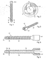
- the device shown in Figure 1 is a first example (not according to the claimed invention) of a pedicle screw 11 being a pedicle anchor device body of a pedicle anchor device.
- the device body 11 is formed as a sheath element with a proximal wall portion 11.1 that surrounds a longitudinal bore 13 open to the proximal side of the sheath element.
- a distal end portion 11.2 terminates the longitudinal bore distally.
- a collar portion 11.3 serves as proximal head to which further elements can be fastened.
- the distal end portion (meaning that it forms the distal end of the longitudinal bore) is also at the distal end of the pedicle anchor device body; in other embodiments, the device body may comprise a portion distally of the The distal end portion may optionally form a directing structure as illustrated in more detail further below.
- the wall portion of the sheath element has at least one hole, namely four holes 14 equally distributed around the circumference of the sheath element in the depicted embodiment.
- the pedicle anchor device further comprises a liquefiable element 21, for example a polymer pin 21 that is adapted to the sheath element to be inserted in the longitudinal bore 13 from the proximal side, as illustrated for example in Fig. 10 .
- a liquefiable element 21 for example a polymer pin 21 that is adapted to the sheath element to be inserted in the longitudinal bore 13 from the proximal side, as illustrated for example in Fig. 10 .
- the liquefiable element 21 is inserted and brought into a position where it abuts against the distal end portion. While the sheath element is in contact with hard tissue and/or hard tissue replacement material, the liquefiable element is pressed against the distal end portion while energy impinges from the proximal side. Under the additional effect of the pressing force, the liquefied material of the liquefiable element is pressed out through the holes 14 and into structures, like pores, surface unevenness, inhomogeneities etc. of the hard tissue and/or hard tissue replacement material.
- An advantageous way of causing energy to impinge is by way of a sonotrode 35 (see for example Fig. 10 ) that is pressed against a proximal end face of the liquefiable element while mechanical vibrations are coupled into the sonotrode.
- the mechanical vibrations are coupled into the liquefiable element 21, and the vibration energy is at least partly absorbed at the interface to the distal end portion causing the polymer material of the liquefiable element to at least locally liquefy at this interface.
- Figure 2 depicts a section along the plane II-II in Figure 1 illustrating optional features that may be realized in any embodiment, either alone or in combination.
- the principle of the outflow holes being asymmetrical with respect to a radial direction may be implemented independent of any aspect of the invention. It may be used for medical devices comprising a sheath element suitable of being brought into contact, during a surgical operation, with live hard tissue and/or with hard tissue replacement material, which is based on the liquefiable material being inserted (pre-assembled or inserted in situ) in a longitudinal bore of the sheath element and where the sheath element comprises at least one hole in the sheath element wall, through which the liquefied material is pressed from the longitudinal bore into the structures (pores or cavities or other structures) of the bone tissue or other hard tissue or hard tissue replacement material in which anchoring is desired.
- a bone screw namely a further pedicle screw 41 (not according to the claimed invention) is depicted.
- the pedicle screw is, together with a thermoplastic element not shown in Figs. 3-5 , an embodiment of a pedicle anchor device according to the first aspect of the invention.
- the pedicle screw 41 comprises a screw head 42, a threaded section 43, and a distal end portion 44.
- the pedicle screw further comprises a longitudinal through bore 13 that, towards the distal end, comprises a narrowed portion so that a shoulder 11.5 for stopping an insert element (not shown in Fig. 5 ) acting, during the liquefaction, as the distal end of the longitudinal bore 13 and inserted from the proximal side is formed.
- the thread has a constant outer diameter (major diameter), whereas a core diameter (minor diameter) is larger at the proximal side than at the distal side. More concretely, in the depicted embodiment, in a central portion of the threaded section the core diameter gradually reduces, whereas in peripheral portions the core diameter is constant. In other, alternative embodiments, the core diameter is constant, is gradually reduced along the entire length of the threaded section, or the core diameter has a stepped characteristics as taught in WO 90/02526 , or has any other characteristics. Also, the outer diameter of the threaded section need not be constant. Generally, the approach according to the first aspect of the invention may be combined with any suitable outer thread.
- the bore diameter is comparably large to make insertion of the liquefiable element - that may be a polymer pin - possible.
- the bore diameter at the more proximal portion of the threaded section is 3.1 mm and at the distal portion of the threaded section is 2.9 mm, whereas the major diameter is 6.6 mm and the minor diameter is between 4.4 mm and 5.3 mm. The resulting wall strength has proven to be sufficient.
- the screw head is flattened and comprises an inner thread that can be used for coupling to an apparatus for automated implantation, as described in US patent application No. 61/259,383 incorporated herein by reference.
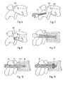
- Figure 6 depicts a vertebra 121.
- the access is prepared by pre-drilling a bore 122 at the appropriate position in a region near the transverse process.
- the bore 122 may merely go through the cortical bone, or it may reach through the pedicle into the vertebral body and over an entire length of the pedicle screw to be introduced later, or a substantial portion thereof.
- the pre-drilled hole may be drilled to have an undersize.
- the pedicle screw 41 is inserted conventionally by screwing. ( Fig.
- the orientational stability due to the limited strength of the cancellous bone in the vertebral body, may be limited as illustrated by the double arrow in Fig. 9 .
- the liquefiable element 21 being a pin of a thermoplastic polymer is inserted. If the screw is of the type having a separate insert element for the directing structure, prior to or together with the liquefiable element 21 also the insert element 18 is inserted. Then, as shown in Figure 10 , the sonotrode 35 acts to press the liquefiable element against the stop face while coupling mechanical vibrations into the liquefiable element.
- the resulting liquefaction, followed by a re-solidification is illustrated in Fig. 11.
- Figure 11 illustrates the situation during the anchoring process.
- Liquefied and re-solidifying material portions 22 pressed into the surrounding bone tissue of the vertebra and interpenetrating structures of the latter strengthen the cancellous bone tissue.
- the connection provides a solid anchoring.
- Figure 12 illustrates, in partial section, the two pedicle screws 41 inserted by this method.
- the pedicle anchor device 101 shown in Figures 13 and 14 is a example of a device according to the invention.
- the head portion 102 is similar to the head portion of the pedicle screw described referring to Figures 3- 5 .
- Its inner thread may not only be used for coupling to an apparatus for automated implantation but also for the fixation of a spine stabilizing rod.
- the shaft portion 103 does not have a circular cross section (such as for example a shape that corresponds essentially to a circular cylinder or to a cone) and does therefore not have an outer thread. Rather, the shaft portion is flat and is helically twisted. In the depicted configuration, the total angular twist amounts to about 90°, so that a distal end portion of the shaft is approximately perpendicular to a proximal portion intended to be located in the pedicle after implantation.
- the pedicle anchor device may have a 'vertical' orientation at the proximal end, an inclined orientation following the direction of longest extension of the pedicle cross section within the pedicle and a 'horizontal' orientation within the vertebral body.
- the pedicle anchor device comprises a longitudinal bore 13 for a thermoplastic element (not shown) to be inserted.
- Two radial holes 14 reach from the longitudinal bore to an outside. They are arranged near to the distal end of the shaft portion at the two flat sides.
- a thermoplastic element is inserted in the longitudinal bore and then for anchoring mechanical energy is coupled into the thermoplastic element to liquefy portions thereof and to press the liquefied portions out of the radial holes into structures of the surrounding tissue.
- the pedicle anchor device - like other embodiments - has an additional distal (axial) hole 19 that may for example serve as guiding hole together with a Kirschner wire and/or may serve for pressing out further portions of liquefied material into tissue at the distal end of the device.
- an additional distal (axial) hole may especially be advantageous in embodiments, in which like in the embodiment of Figures 13 and 14 the distal end portion of the longitudinal bore against which the liquefiable material is pressed during liquefaction is not formed by a separate insert but by the device body itself.
- a device of the kind shown in figures 13 and 14 may further optionally comprise a directing structure that is structured angularly with respect to a longitudinal axis of the longitudinal bore to direct different portions of liquefiable material from a liquefiable element to different ones of the holes 14, as described hereinafter.
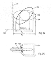
- FIG. 24 the extension of bone tissue within the pedicle in which an pedicle anchor device may be anchored is schematically shown by the ellipse 134.
- the axes 131, 132 are parallel to the sagittal plane and the transversal plane, respectively.
- Prior art pedicle anchor devices are restricted to a circular cross section.
- the maximal possible cross section thus corresponds to the dashed line 135 in Fig. 24 .
- a pedicle anchor device according to aspects of the invention does not need to be circular, due to the new anchoring technique with liquefiable material pressed out of the longitudinal bore.
- the entire available cross section of the pedicle may be used if an anchoring device with a for example elliptical cross section is used, leading to an enhanced effective anchoring cross section d 1 .
- an anchoring device with a for example elliptical cross section
- the orientation of the more distal implant sections may be different from the orientation within the pedicle, leading to an even more enhanced effective anchoring cross section d 2 . This brings an improved anchoring strength.
- a pedicle anchor device with a reduced cross section may be used, so that the overall cross sectional area is smaller than the cross sectional area of prior art pedicle screws (as illustrated by the dashed line), so that the implantation causes less impact on the tissue.
- FIG. 25 shows a cross section through a portion of a vertebra along the vertical plane parallel to the pedicle anchoring device insertion axis.
- the pedicle anchoring device's 151 length is adapted to the size of the patient's vertebra so that the anchoring device ends where the pedicle adjoins the vertebral body. This has the following advantages:
- the head portion and the shaft portion are illustrated to be one-piece, this is not necessary. Rather, they may be separate pieces somehow attached to each other.
- the connection between the shaft portion and the head may be so that the orientation of the head portion relative to the shaft portion may be adjustable.
- the head portion may be rotatable about an axis, or the adjustability may be multi-axial.
- the multi-tiered anchoring or augmentation as described herein with a first liquefaction process taking place with a first directing structure - of the sheath element or of an initially separate insert element - the subsequent (after an at least partial re-solidification of the liquefied material) addition of a further directing structure of a (second) insert element and then a second liquefaction may be applied independent of the aspects of the invention.
- FIGS 15-19 yet further embodiments of the anchoring device or details thereof are illustrated.
- These further embodiments/details comprise a directing structure that is structured angularly with respect to a longitudinal axis of the longitudinal bore to direct different portions of the liquefiable material to different ones of the holes.
- the directing structure comprises a ramp portion 12 sloping away from a center around the longitudinal axis.
- the ramp portion 12 is conical, thus its section with a plane going through the longitudinal axis is a straight line. In alternative embodiments, it could be spherical and concave.
- the wall portion of the sheath element has four holes 14 equally distributed around the circumference of the sheath element.
- the directing structure further comprises walls 15 angularly sub-dividing a portion of the longitudinal bore volume communicating with the holes 14. In the depicted embodiment, the walls have a constant thickness and comprise a proximal edge 15.1 that in the depicted embodiment slope towards the center
- the angular structuring of the directing structure with the walls between the holes firstly has the function to separate portions of the liquefiable element during liquefaction. Due to this, approximately equal amounts of liquefied material is pressed out of every one of the four holes 14, even if the liquefied material while being pressed out of the different holes 14 encounters different resistance.
- a second function of the walls 15 that protrude distally from the directing structure body and the stop face is that of energy directors.
- the liquefiable material will have a tendency to start liquefying, under the impact of mechanical vibrations, at edges or other pronounced structures either of the sheath element or of the liquefiable element itself.
- the energy directing function of the walls 15 is a means for causing the liquefaction to start and take place in vicinity of the holes 14 and not, for example, at the proximal interface to the sonotrode where too early an onset of liquefaction would be undesired.
- Figures 18 and 19 show a detail of a pedicle anchor device, for example as illustrated in Figures 3-5 . Compared to the embodiment of Figures 15-17 , the embodiment of Figures 18 and 19 incorporates the following features:
- the sheath element may comprise at least one interior axial groove that reaches from the proximal end of the sheath element to a distal stop and in which a corresponding number of ridges or tongues of the insert element is guided.
- the insert element may comprise a spring deflected, during insertion in the sheath element, radially inward against a spring force and forcing a stop flange portion into an annular stop groove of the sheath element at the appropriate axial position.
- Various other stop structures are possible.
- an insert element 18 may comprise an isotropic stop face instead of an angularly structured stop face.
- a different number of holes may be present, for example one, two, three, five, ... holes.
- the directing structure, if any, is shaped accordingly.
- the holes may have any appropriate shape, such as circular, elongate, ...
Landscapes
- Health & Medical Sciences (AREA)
- Orthopedic Medicine & Surgery (AREA)
- Life Sciences & Earth Sciences (AREA)
- Surgery (AREA)
- Animal Behavior & Ethology (AREA)
- Veterinary Medicine (AREA)
- Public Health (AREA)
- General Health & Medical Sciences (AREA)
- Engineering & Computer Science (AREA)
- Biomedical Technology (AREA)
- Heart & Thoracic Surgery (AREA)
- Medical Informatics (AREA)
- Nuclear Medicine, Radiotherapy & Molecular Imaging (AREA)
- Molecular Biology (AREA)
- Neurology (AREA)
- Oral & Maxillofacial Surgery (AREA)
- Dentistry (AREA)
- Epidemiology (AREA)
- Transplantation (AREA)
- Ceramic Engineering (AREA)
- Cardiology (AREA)
- Vascular Medicine (AREA)
- Mechanical Engineering (AREA)
- Surgical Instruments (AREA)
- Prostheses (AREA)
- Materials For Medical Uses (AREA)
- Rheumatology (AREA)
Priority Applications (3)
| Application Number | Priority Date | Filing Date | Title |
|---|---|---|---|
| PL10778830T PL2498694T3 (pl) | 2009-11-09 | 2010-11-09 | Urządzenie medyczne, przyrząd, oraz sposób chirurgiczny |
| EP16189811.9A EP3130299A1 (en) | 2009-11-09 | 2010-11-09 | Medical device and aparatus |
| EP15157312.8A EP2898843B1 (en) | 2009-11-09 | 2010-11-09 | Medical device and apparatus |
Applications Claiming Priority (3)
| Application Number | Priority Date | Filing Date | Title |
|---|---|---|---|
| US25938309P | 2009-11-09 | 2009-11-09 | |
| US38824310P | 2010-09-30 | 2010-09-30 | |
| US39458010P | 2010-10-19 | 2010-10-19 |
Related Child Applications (3)
| Application Number | Title | Priority Date | Filing Date |
|---|---|---|---|
| EP15157312.8A Division EP2898843B1 (en) | 2009-11-09 | 2010-11-09 | Medical device and apparatus |
| EP15157312.8A Division-Into EP2898843B1 (en) | 2009-11-09 | 2010-11-09 | Medical device and apparatus |
| EP16189811.9A Division EP3130299A1 (en) | 2009-11-09 | 2010-11-09 | Medical device and aparatus |
Publications (2)
| Publication Number | Publication Date |
|---|---|
| EP2498694A1 EP2498694A1 (en) | 2012-09-19 |
| EP2498694B1 true EP2498694B1 (en) | 2015-04-15 |
Family
ID=43431892
Family Applications (7)
| Application Number | Title | Priority Date | Filing Date |
|---|---|---|---|
| EP16189811.9A Withdrawn EP3130299A1 (en) | 2009-11-09 | 2010-11-09 | Medical device and aparatus |
| EP10778829.1A Not-in-force EP2498702B1 (en) | 2009-11-09 | 2010-11-09 | Medical apparatus |
| EP16195257.7A Active EP3141202B1 (en) | 2009-11-09 | 2010-11-09 | Medical device, apparatus |
| EP15161815.4A Active EP2910207B1 (en) | 2009-11-09 | 2010-11-09 | Medical device, apparatus |
| EP15157312.8A Active EP2898843B1 (en) | 2009-11-09 | 2010-11-09 | Medical device and apparatus |
| EP10778830.9A Not-in-force EP2498694B1 (en) | 2009-11-09 | 2010-11-09 | Medical device, apparatus, and surgical method |
| EP10778828.3A Active EP2498693B1 (en) | 2009-11-09 | 2010-11-09 | Medical device, chirurgical apparatus |
Family Applications Before (5)
| Application Number | Title | Priority Date | Filing Date |
|---|---|---|---|
| EP16189811.9A Withdrawn EP3130299A1 (en) | 2009-11-09 | 2010-11-09 | Medical device and aparatus |
| EP10778829.1A Not-in-force EP2498702B1 (en) | 2009-11-09 | 2010-11-09 | Medical apparatus |
| EP16195257.7A Active EP3141202B1 (en) | 2009-11-09 | 2010-11-09 | Medical device, apparatus |
| EP15161815.4A Active EP2910207B1 (en) | 2009-11-09 | 2010-11-09 | Medical device, apparatus |
| EP15157312.8A Active EP2898843B1 (en) | 2009-11-09 | 2010-11-09 | Medical device and apparatus |
Family Applications After (1)
| Application Number | Title | Priority Date | Filing Date |
|---|---|---|---|
| EP10778828.3A Active EP2498693B1 (en) | 2009-11-09 | 2010-11-09 | Medical device, chirurgical apparatus |
Country Status (15)
| Country | Link |
|---|---|
| US (8) | US8974506B2 (zh) |
| EP (7) | EP3130299A1 (zh) |
| JP (5) | JP5882902B2 (zh) |
| KR (4) | KR101750579B1 (zh) |
| CN (4) | CN105962993B (zh) |
| AU (2) | AU2010314741B2 (zh) |
| BR (2) | BR112012010903B1 (zh) |
| CA (2) | CA2780285C (zh) |
| ES (5) | ES2695424T3 (zh) |
| HK (4) | HK1175678A1 (zh) |
| HU (1) | HUE026401T2 (zh) |
| IL (3) | IL219383A (zh) |
| PL (3) | PL2498694T3 (zh) |
| RU (4) | RU2712028C2 (zh) |
| WO (3) | WO2011054123A1 (zh) |
Cited By (1)
| Publication number | Priority date | Publication date | Assignee | Title |
|---|---|---|---|---|
| RU2661052C1 (ru) * | 2017-07-21 | 2018-07-11 | Игорь Георгиевич Киселев | Набор имплантов для образования наддужковой конструкции при остеосинтезе позвоночника животных |
Families Citing this family (66)
| Publication number | Priority date | Publication date | Assignee | Title |
|---|---|---|---|---|
| US20180228621A1 (en) | 2004-08-09 | 2018-08-16 | Mark A. Reiley | Apparatus, systems, and methods for the fixation or fusion of bone |
| US8974505B2 (en) * | 2008-06-16 | 2015-03-10 | Anna G. U. Sawa | Venting/pressure adjustment to aid in delivery of material into an anatomic region via a cannula |
| US8974506B2 (en) * | 2009-11-09 | 2015-03-10 | Spinewelding Ag | Medical device, apparatus, and surgical method |
| BR112012018010B1 (pt) | 2010-01-27 | 2020-10-13 | Sportwelding Gmbh | "conjunto para prender tecido ou um elemento protético em uma abertura proporcionada em um osso humano ou animal". abertura proporcionada em um osso humano ou animal |
| WO2012041376A1 (en) | 2010-09-30 | 2012-04-05 | Stryker Trauma Gmbh | System for inserting a pin into a screw |
| PL3045129T3 (pl) * | 2010-09-30 | 2018-08-31 | Spinewelding Ag | Chirurgiczna płyta stabilizatora |
| CA2824881C (en) * | 2011-01-14 | 2020-06-02 | DePuy Synthes Products, LLC | Elongated fixation element |
| BR112013018116B1 (pt) * | 2011-01-28 | 2020-12-08 | Sportwelding Gmbh | dispositivo para fixar uma âncora de sutura com uma sutura em uma abertura de tecido duro |
| WO2012129119A2 (en) * | 2011-03-18 | 2012-09-27 | Raed M. Ali, M.D., Inc. | Transpedicular access to intervertebral spaces and related spinal fusion systems and methods |
| US9265620B2 (en) * | 2011-03-18 | 2016-02-23 | Raed M. Ali, M.D., Inc. | Devices and methods for transpedicular stabilization of the spine |
| CN103841927A (zh) * | 2011-06-09 | 2014-06-04 | 齐默尔膝部创造物公司 | 用于软骨下关节修复的器械和装置 |
| ITMI20120312A1 (it) * | 2012-02-29 | 2013-08-30 | Matteo Antonini | Dispositivo medico per sistemi protesici dentali, sistema protesico dentale, uso del dispositivo medico e metodo di formazione di sistemi protesici |
| EP2819598B1 (en) * | 2012-02-29 | 2019-07-03 | Stryker European Holdings I, LLC | System for handling an augmentation implant |
| PL219189B1 (pl) * | 2012-03-06 | 2015-03-31 | Lfc Spółka Z Ograniczoną Odpowiedzialnością | Dystansowe urządzenie międzytrzonowe do wprowadzania do trzonu kręgowego biomateriału |
| WO2013134670A1 (en) | 2012-03-09 | 2013-09-12 | Si-Bone Inc. | Integrated implant |
| US10363140B2 (en) | 2012-03-09 | 2019-07-30 | Si-Bone Inc. | Systems, device, and methods for joint fusion |
| CN104334092A (zh) | 2012-05-04 | 2015-02-04 | 西-博恩公司 | 穿孔植入物 |
| CN102715941B (zh) * | 2012-06-26 | 2014-03-05 | 南方医科大学 | 一种改进型可灌注椎弓根螺钉 |
| EP2967763A1 (en) * | 2013-03-12 | 2016-01-20 | Azenium IP Limited | Expandable dental implant |
| JP6836899B2 (ja) | 2013-03-14 | 2021-03-03 | ラエド エム.アリ,エム.ディー.,インク. | 側方椎体間固定装置、システム、及び方法 |
| US10687962B2 (en) | 2013-03-14 | 2020-06-23 | Raed M. Ali, M.D., Inc. | Interbody fusion devices, systems and methods |
| US9936983B2 (en) * | 2013-03-15 | 2018-04-10 | Si-Bone Inc. | Implants for spinal fixation or fusion |
| CN103142302A (zh) * | 2013-03-19 | 2013-06-12 | 胡晓晖 | 骨螺钉 |
| CN104414725B (zh) * | 2013-09-06 | 2018-08-07 | 宝楠生技股份有限公司 | 具微孔的固定螺钉 |
| EP2856958A1 (en) * | 2013-10-07 | 2015-04-08 | Arthrex Inc | Cannulated bone screw |
| US11147688B2 (en) | 2013-10-15 | 2021-10-19 | Si-Bone Inc. | Implant placement |
| EP3193752B1 (en) | 2014-09-18 | 2020-07-22 | SI-Bone, Inc. | Matrix implant |
| US10166033B2 (en) | 2014-09-18 | 2019-01-01 | Si-Bone Inc. | Implants for bone fixation or fusion |
| CN105640669A (zh) * | 2014-11-09 | 2016-06-08 | 祝桂涛 | 三d生物力传导人工假体 |
| US11234747B2 (en) | 2015-02-25 | 2022-02-01 | National University Corporation Tokyo Medical And Dental University | Medical device, device structures for dentistry, for head and neck surgery and for orthopedic surgery, and method for bonding medical device to bone |
| US10376206B2 (en) | 2015-04-01 | 2019-08-13 | Si-Bone Inc. | Neuromonitoring systems and methods for bone fixation or fusion procedures |
| US9995600B2 (en) | 2015-09-01 | 2018-06-12 | General Electric Company | Multi-axis magneto-resistance sensor package |
| JP6901471B2 (ja) | 2015-09-30 | 2021-07-14 | コーニンクレッカ フィリップス エヌ ヴェKoninklijke Philips N.V. | 骨組織に移植するためのシステム及び方法 |
| CN108024826B (zh) | 2015-09-30 | 2020-11-27 | 斯伯威丁股份公司 | 包括医疗装置的系统 |
| EP3389520B1 (en) * | 2015-12-15 | 2023-11-01 | Nexilis AG | Devices for minimally invasive immediate implant stabilization |
| EP4023178B1 (en) * | 2016-02-25 | 2023-11-29 | Biedermann Technologies GmbH & Co. KG | Bone anchor |
| CH712758A2 (de) * | 2016-07-29 | 2018-01-31 | Z-Systems AG | Dentalimplantat und Implantationsset. |
| CH712757A2 (de) * | 2016-07-29 | 2018-01-31 | Z-Systems AG | Dentalimplantat und Implantationsset. |
| US20210068931A1 (en) * | 2016-07-29 | 2021-03-11 | Woodwelding Ag | Dental implant and dental implant system |
| EP3509516A1 (en) * | 2016-09-07 | 2019-07-17 | Spinewelding AG | Implant fixation |
| US10052140B2 (en) | 2016-10-05 | 2018-08-21 | Stryker European Holdings I, Llc | Apparatus and method for fenestrated screw augmentation |
| ES2672265B1 (es) * | 2016-11-07 | 2019-04-10 | Inst Biomecanico De Barcelona S L | Dispositivo para fusion intervertebral que comprende un tornillo de estabilizacion intervertebral y una composicion para remodelacion osea |
| US11548233B2 (en) | 2017-01-19 | 2023-01-10 | Ikea Supply Ag | Method of anchoring a connector element, a machine for carrying out the method and a connector element anchoring kit |
| US20200138495A1 (en) | 2017-02-07 | 2020-05-07 | Spinewelding Ag | Implant fixation |
| CN110678222A (zh) * | 2017-05-23 | 2020-01-10 | 神经毫微股份公司 | 用于插入神经组织的器件 |
| EP3687422A4 (en) | 2017-09-26 | 2021-09-22 | SI-Bone, Inc. | SYSTEMS AND PROCESSES FOR DECORTICATION OF THE SACROILIAC JOINT |
| FR3074028A1 (fr) * | 2017-11-24 | 2019-05-31 | Jean-Marc Valiadis | Procede d'evaluation de la resistance maximale a l'arrachement d'une vis d'ancrage implantee dans une vertebre |
| WO2019137921A1 (en) | 2018-01-09 | 2019-07-18 | Spinewelding Ag | Implant fixation |
| CN111936067A (zh) | 2018-02-08 | 2020-11-13 | 伍德韦尔丁公司 | 由超声焊极和导向套管构成的系统 |
| US20210045786A1 (en) | 2018-02-08 | 2021-02-18 | Spinewelding Ag | System and method for establishing an anchorage or reinforcement in an object with the aid of in situ liquefaction and displacement of a material having thermoplastic properties |
| CN111989066A (zh) * | 2018-04-17 | 2020-11-24 | 伍德韦尔丁公司 | 将种植牙、牙基台和牙上层结构附接至彼此 |
| US10624762B2 (en) * | 2018-09-07 | 2020-04-21 | Orthorebirth Usa | Bone graft delivery device for minimally invasive surgery |
| CA3116618A1 (en) | 2018-12-03 | 2020-06-11 | Woodwelding Ag | Surgical apparatus, surgical system and method of setting up a surgical apparatus |
| DE102019000965B4 (de) | 2019-02-09 | 2020-12-24 | Mimeo Medical Gmbh | Knochenverankerungsvorrichtung für den Pedikelzugang |
| EP3923829A4 (en) | 2019-02-14 | 2022-12-14 | SI-Bone, Inc. | IMPLANTS FOR SPINE FIXATION AND/OR FUSION |
| US11369419B2 (en) | 2019-02-14 | 2022-06-28 | Si-Bone Inc. | Implants for spinal fixation and or fusion |
| EP3930597A1 (en) | 2019-02-27 | 2022-01-05 | Beacon Biomedical, LLC | Fastening device for acquiring bone marrow aspirate |
| JP2023505055A (ja) | 2019-11-27 | 2023-02-08 | エスアイ-ボーン・インコーポレイテッド | 骨安定インプラント及び仙腸関節を横切る配置方法 |
| WO2021204905A1 (en) | 2020-04-08 | 2021-10-14 | Spinewelding Ag | Bone implant |
| WO2021204908A1 (en) | 2020-04-08 | 2021-10-14 | Spinewelding Ag | Fenestrated bone anchor |
| WO2021204907A1 (en) | 2020-04-08 | 2021-10-14 | Spinewelding Ag | Surgical system comprising an implant and a bone anchor suitable for fixating the implant relative to bone tissue |
| BR102020011004A2 (pt) * | 2020-06-01 | 2021-12-14 | M3 Health Indústria E Comércio De Produtos Médicos, Odontológicos E Correlatos S.A. | Implantes e parafusos osseointegráveis com superfície estruturalmente porosa, processo para preparação dos ditos implantes e parafusos e usos dos ditos implantes |
| DE102020004184A1 (de) * | 2020-07-11 | 2022-01-13 | Mimeo Medical Gmbh | Klingenartige Osteosynthesevorrichtung |
| JP2023553120A (ja) | 2020-12-09 | 2023-12-20 | エスアイ-ボーン・インコーポレイテッド | 仙腸関節安定化インプラントおよびインプラント方法 |
| US20230165612A1 (en) * | 2020-12-15 | 2023-06-01 | Blue Sky Technologies, LLC | Surgical Fastener Combination |
| USD974558S1 (en) | 2020-12-18 | 2023-01-03 | Stryker European Operations Limited | Ultrasonic knife |
Family Cites Families (101)
| Publication number | Priority date | Publication date | Assignee | Title |
|---|---|---|---|---|
| US3025853A (en) | 1958-07-07 | 1962-03-20 | Christopher A Mason | Fixation device for fractured femur |
| CA1227902A (en) * | 1984-04-02 | 1987-10-13 | Raymond G. Tronzo | Fenestrated hip screw and method of augmented internal fixation |
| SU1337074A1 (ru) * | 1985-06-21 | 1987-09-15 | В.В.Коптюх | Устройство дл остеосинтеза |
| WO1990002526A1 (en) | 1988-09-09 | 1990-03-22 | Australian Defence Industries Pty. Limited | Screw |
| US4978349A (en) | 1989-08-03 | 1990-12-18 | Synthes (U.S.A.) | Fixation plate |
| US5492442A (en) | 1990-11-27 | 1996-02-20 | National Medical Specialty, Inc. | Bone screw with improved threads |
| CH682300A5 (zh) * | 1990-12-17 | 1993-08-31 | Synthes Ag | |
| JPH0751292A (ja) | 1993-08-16 | 1995-02-28 | Yoshihiro Kishigami | 骨内留置用骨ネジ |
| US5752965A (en) | 1996-10-21 | 1998-05-19 | Bio-Vascular, Inc. | Apparatus and method for producing a reinforced surgical fastener suture line |
| WO1998051241A1 (en) | 1997-05-16 | 1998-11-19 | Norian Corporation | Implantable re-bar devices |
| US6436100B1 (en) * | 1998-08-07 | 2002-08-20 | J. Lee Berger | Cannulated internally threaded bone screw and reduction driver device |
| ES2245047T3 (es) | 1998-11-26 | 2005-12-16 | Synthes Ag Chur | Tornillo para huesos. |
| US6048343A (en) * | 1999-06-02 | 2000-04-11 | Mathis; John M. | Bone screw system |
| US20020077550A1 (en) | 1999-10-05 | 2002-06-20 | Rabiner Robert A. | Apparatus and method for treating gynecological diseases using an ultrasonic medical device operating in a transverse mode |
| DE19949285C2 (de) * | 1999-10-12 | 2002-08-14 | Impag Gmbh Medizintechnik | Knochenschraube |
| US6565572B2 (en) | 2000-04-10 | 2003-05-20 | Sdgi Holdings, Inc. | Fenestrated surgical screw and method |
| US6554830B1 (en) * | 2000-04-10 | 2003-04-29 | Sdgi Holdings, Inc. | Fenestrated surgical anchor and method |
| US6409730B1 (en) * | 2000-05-31 | 2002-06-25 | Synthes (Usa) | Humeral spiral blade |
| DE10055891A1 (de) * | 2000-11-10 | 2002-06-06 | Biedermann Motech Gmbh | Knochenschraube |
| PT1339335E (pt) * | 2000-12-08 | 2005-01-31 | Synthes Ag | Dipositivo para a fixacao de ossos, em particular de corpos de vertebra, um em relacao ao outro |
| ES2271212T3 (es) * | 2001-03-02 | 2007-04-16 | Woodwelding Ag | Impantes y dispositivo para unir partes de tejido. |
| JP2003159258A (ja) * | 2001-11-29 | 2003-06-03 | Ichiro Okutsu | 流動体注入用の骨折治療器具 |
| RU2289350C2 (ru) * | 2002-05-27 | 2006-12-20 | Федеральное государственное учреждение науки "Российский научный центр "Восстановительная травматология и ортопедия" им. акад. Г.А.Илизарова Федерального агентства по здравоохранению и социальному развитию" (ФГУН "РНЦ "ВТО" им. акад. Г.А.Илизарова Росздрава") | Способ лечения острой позвоночно-спинномозговой травмы |
| US6730095B2 (en) * | 2002-06-26 | 2004-05-04 | Scimed Life Systems, Inc. | Retrograde plunger delivery system |
| US7008226B2 (en) * | 2002-08-23 | 2006-03-07 | Woodwelding Ag | Implant, in particular a dental implant |
| DE10246386B4 (de) * | 2002-10-04 | 2008-08-07 | Biedermann Motech Gmbh | Knochenschraube, Knochenfixationseinrichtung und Halteelement |
| CN2577785Y (zh) * | 2002-11-22 | 2003-10-08 | 北京大学第三医院 | 一种椎弓根螺钉 |
| DE10260222B4 (de) * | 2002-12-20 | 2008-01-03 | Biedermann Motech Gmbh | Rohrförmiges Element für ein in der Wirbelsäulen- oder der Knochenchirurgie zu verwendendes Implantat und Implantat mit einem solchen Element |
| US7473267B2 (en) | 2003-04-25 | 2009-01-06 | Warsaw Orthopedic, Inc. | System and method for minimally invasive posterior fixation |
| US7608097B2 (en) * | 2003-04-29 | 2009-10-27 | Millennium Medical Technologies | Bone screw with fluid delivery structure |
| US7354442B2 (en) * | 2003-05-05 | 2008-04-08 | Warsaw Orthopedic, Inc. | Bone anchor and methods of using the same |
| US20040230195A1 (en) * | 2003-05-14 | 2004-11-18 | Inion Ltd. | Soft-tissue screw |
| US7608062B2 (en) * | 2003-07-15 | 2009-10-27 | Spinal Generations, Llc | Method and device for delivering medicine to bone |
| US7575572B2 (en) * | 2003-07-15 | 2009-08-18 | Spinal Generations, Llc | Method and device for delivering medicine to bone |
| US7527611B2 (en) * | 2003-07-15 | 2009-05-05 | Spinal Generations, Llc | Method and device for delivering medicine to bone |
| US8062270B2 (en) * | 2003-07-15 | 2011-11-22 | Spinal Generations, Llc | Method and device for delivering medicine to bone |
| US8870836B2 (en) * | 2003-07-15 | 2014-10-28 | Spinal Generations, Llc | Method and device for delivering medicine to bone |
| US7699852B2 (en) * | 2003-11-19 | 2010-04-20 | Zimmer Spine, Inc. | Fenestrated bone tap and method |
| WO2005079696A1 (de) * | 2004-02-20 | 2005-09-01 | Woodwelding Ag | In knochengewebe zu implantierendes implantat und verfahren zu dessen herstellung und implantation |
| JP4494459B2 (ja) * | 2004-03-03 | 2010-06-30 | ジンテーズ ゲゼルシャフト ミト ベシュレンクテル ハフツング | 骨固着手段 |
| JP4213609B2 (ja) * | 2004-03-09 | 2009-01-21 | 昭和医科工業株式会社 | ロッド固定用補助器具 |
| RU2285483C2 (ru) * | 2004-11-25 | 2006-10-20 | Общество с ограниченной ответственностью "КОНМЕТ" (ООО "КОНМЕТ") | Устройство для проведения стабилизирующей операции на позвоночнике (его варианты) и способ проведения стабилизирующей операции на позвоночнике |
| WO2006070961A2 (en) * | 2004-12-31 | 2006-07-06 | Ji-Hoon Her | Pedicle screw and device for injecting bone cement into bone |
| US20060195106A1 (en) | 2005-02-02 | 2006-08-31 | Jones Bryan S | Ultrasonic cutting device |
| WO2007014142A2 (en) * | 2005-07-25 | 2007-02-01 | Piezoinnovations | Ultrasonic transducer devices and methods of manufacture |
| US20070161985A1 (en) * | 2005-12-05 | 2007-07-12 | Kentomia, Llc . | Screws configured to engage bones, and methods of attaching implants to skeletal regions |
| US8372126B2 (en) * | 2006-04-21 | 2013-02-12 | Warsaw Orthopedic, Inc. | Surgical fasteners with mechanical and osteogenic fixation means |
| US20070260250A1 (en) | 2006-05-05 | 2007-11-08 | Sdgi Holdings, Inc. | Reinforcement of boney material surrounding a bone implant |
| RU2311149C1 (ru) * | 2006-05-11 | 2007-11-27 | Государственное учреждение Российский научный центр хирургии РАМН (РНЦХ РАМН) | Устройство для кифопластики и способ кифопластики |
| EP2065017B1 (en) | 2006-08-22 | 2014-01-01 | Mitsubishi Electric Corporation | Laser processing apparatus |
| PL2314239T3 (pl) * | 2006-09-20 | 2016-09-30 | Urządzenie do wszczepiania do ludzkiej i zwierzęcej tkanki | |
| EP3326544B1 (en) | 2006-09-20 | 2020-04-08 | Woodwelding AG | Implant and implantation device |
| ES2328841T3 (es) * | 2006-11-10 | 2009-11-18 | Biedermann Motech Gmbh | Clavo de anclaje oseo. |
| KR101538135B1 (ko) * | 2006-11-10 | 2015-07-29 | 비이더만 테크놀로지스 게엠베하 & 코. 카게 | 뼈 고정 네일 |
| WO2008063915A2 (en) * | 2006-11-13 | 2008-05-29 | Kfx Medical Corporation | System and method for attaching soft tissue to bone |
| WO2008058403A1 (en) * | 2006-11-14 | 2008-05-22 | Synthes Gmbh | Device for fixing articulation fragments having cartilage |
| ATE551962T1 (de) * | 2006-11-22 | 2012-04-15 | Biedermann Motech Gmbh | Knochenverankerungsvorrichtung |
| WO2008095327A1 (en) * | 2007-02-08 | 2008-08-14 | Woodwelding Ag | Implant, method of preparing an implant, implantation method, and kit of parts |
| US20080249574A1 (en) * | 2007-03-20 | 2008-10-09 | Mccombs Mary | Bone Screw System |
| US8551124B2 (en) * | 2007-04-20 | 2013-10-08 | Stryker Trauma Gmbh | Implantation pin, fixation device and method for implanting the implantation pin |
| JP5725538B2 (ja) * | 2007-04-20 | 2015-05-27 | ウッドウェルディング・アクチェンゲゼルシャフト | インプラントシステムおよび該インプラントシステムを含むキット |
| DE602007011244D1 (de) | 2007-07-13 | 2011-01-27 | Stryker Trauma Gmbh | Vorrichtung zur Fixierung von Knochenfrakturen |
| CN101765411B (zh) * | 2007-07-13 | 2012-07-18 | 史塞克创伤有限责任公司 | 断骨固定装置 |
| ES2337510T3 (es) * | 2007-07-13 | 2010-04-26 | Stryker Trauma Gmbh | Pieza manual ultrasonica. |
| ES2357432T3 (es) * | 2007-07-13 | 2011-04-26 | Stryker Trauma Gmbh | Dispositivo para la fijación de fracturas óseas. |
| US7892267B2 (en) | 2007-08-03 | 2011-02-22 | Zimmer Spine, Inc. | Attachment devices and methods for spinal implants |
| EP2205185B1 (en) | 2007-10-30 | 2014-06-18 | Woodwelding AG | Device for producing an anchorage in human or animal tissue |
| EP2222240A4 (en) * | 2007-12-19 | 2012-12-05 | Bassem Georgy | DEVICE AND METHOD FOR ATTACHING AN ORTHOPEDIC FRACTURE |
| GB2460909B (en) * | 2008-01-28 | 2010-09-08 | Mark B Sommers | Bone Nail |
| WO2009117837A1 (en) * | 2008-03-28 | 2009-10-01 | Meinrad Fiechter | Surgical device for osteosynthesis |
| JP2009252898A (ja) * | 2008-04-03 | 2009-10-29 | Toyoda Gosei Co Ltd | 光源装置 |
| AU2009239515B2 (en) | 2008-04-21 | 2015-07-16 | Total Connect Spine, Llc | Posterior spinal fastener |
| JP5584200B2 (ja) * | 2008-05-01 | 2014-09-03 | ウッドウェルディング・アクチェンゲゼルシャフト | 組織中にアンカー固定を確立するための装置および方法 |
| US8974505B2 (en) * | 2008-06-16 | 2015-03-10 | Anna G. U. Sawa | Venting/pressure adjustment to aid in delivery of material into an anatomic region via a cannula |
| EP2687173B1 (en) * | 2008-07-01 | 2017-05-03 | Biedermann Technologies GmbH & Co. KG | Bone anchor with plug member and tool for inserting the plug member into the bone anchor |
| JP5774989B2 (ja) * | 2008-08-13 | 2015-09-09 | スメド−ティーエイ/ティーディー・エルエルシー | 整形外科用ねじ |
| WO2010025386A1 (en) * | 2008-08-29 | 2010-03-04 | Smed-Ta/Td, Llc | Orthopaedic implant |
| RU99699U1 (ru) * | 2008-09-23 | 2010-11-27 | Государственное образовательное учреждение высшего профессионального образования "Уральская государственная медицинская академия Федерального агентства по здравоохранению и социальному развитию" (ГОУ ВПО УГМА Росздрава) | Устройство для закрытой вертебропластики |
| CA2742077A1 (en) * | 2008-10-30 | 2010-05-06 | Depuy Spine, Inc. | Systems and methods for delivering bone cement to a bone anchor |
| ES2547500T3 (es) * | 2009-04-03 | 2015-10-06 | Stryker Trauma Gmbh | Tornillo sónico |
| WO2010123859A2 (en) * | 2009-04-20 | 2010-10-28 | Osteo Innovations Llc | System and method for self filling bone screws |
| EP2269526B1 (en) | 2009-07-01 | 2012-12-19 | Biedermann Technologies GmbH & Co. KG | Instruments for use with a bone anchor with plug member |
| KR101058795B1 (ko) * | 2009-08-31 | 2011-08-23 | 김민석 | 척추 고정용 나사 |
| US8574273B2 (en) * | 2009-09-09 | 2013-11-05 | Innovision, Inc. | Bone screws and methods of use thereof |
| US8747411B2 (en) * | 2009-09-30 | 2014-06-10 | Michael David Mitchell | Fluid delivery and bone screw driver apparatus |
| US8974506B2 (en) * | 2009-11-09 | 2015-03-10 | Spinewelding Ag | Medical device, apparatus, and surgical method |
| US8317837B2 (en) * | 2010-02-05 | 2012-11-27 | Warsaw Orthopedic, Inc. | Connector and method |
| US20120029578A1 (en) * | 2010-02-05 | 2012-02-02 | Sean Suh | Bio-Resorbable Capsule Containing Fenestrated Screw System For Osteoporotic Subject |
| CA2799473C (en) * | 2010-05-14 | 2020-03-10 | Todd Sheppard Saunders | Methods and devices for cooling spinal tissue |
| JP5797748B2 (ja) * | 2010-05-19 | 2015-10-21 | デピュイ・シンセス・プロダクツ・インコーポレイテッド | 骨アンカー |
| WO2012064402A1 (en) * | 2010-11-12 | 2012-05-18 | Silver Bullet Therapeutics, Inc. | Bone implant and systems that controllably releases silver |
| BR112013019027B1 (pt) * | 2011-01-28 | 2021-11-23 | Sportwelding Gmbh | Dispositivo para fixação de uma âncora de sutura ou uma âncora dirigida no tecido rígido |
| US9687285B2 (en) * | 2012-01-25 | 2017-06-27 | Spectrum Spine Ip Holdings, Llc | Fenestrated bone screws and methods of bone fastening and stabilization |
| US20130211466A1 (en) * | 2012-02-15 | 2013-08-15 | Warsaw Orthopedic, Inc. | Bone fastener and methods of use |
| US9173692B1 (en) * | 2012-06-15 | 2015-11-03 | Stc.Unm | Composite metal and bone orthopedic fixation devices |
| US9603644B2 (en) * | 2012-08-07 | 2017-03-28 | Spinal Generations, Llc | Methods and devices for delivery of medicine to bone |
| WO2014055368A1 (en) * | 2012-10-02 | 2014-04-10 | Alphatec Spine, Inc. | Expandable screw and methods of use |
| US9526547B2 (en) * | 2013-03-06 | 2016-12-27 | Rgt Scientific Inc. | Bone screw |
| WO2015030409A1 (ko) * | 2013-08-26 | 2015-03-05 | 경북대학교 산학협력단 | 의료용 삽입 장치 |
| WO2016020014A1 (en) * | 2014-08-08 | 2016-02-11 | Stryker Trauma Gmbh | Slotted augmentation sleeve |
| US20160374740A1 (en) * | 2015-06-23 | 2016-12-29 | Sterling Therapeutics, Llc | Retractable screw guide |
-
2010
- 2010-11-09 US US13/505,784 patent/US8974506B2/en active Active
- 2010-11-09 PL PL10778830T patent/PL2498694T3/pl unknown
- 2010-11-09 HU HUE10778828A patent/HUE026401T2/en unknown
- 2010-11-09 PL PL15157312T patent/PL2898843T3/pl unknown
- 2010-11-09 RU RU2016113372A patent/RU2712028C2/ru active
- 2010-11-09 WO PCT/CH2010/000279 patent/WO2011054123A1/en active Application Filing
- 2010-11-09 KR KR1020127014891A patent/KR101750579B1/ko active IP Right Grant
- 2010-11-09 CA CA2780285A patent/CA2780285C/en active Active
- 2010-11-09 CN CN201610169109.7A patent/CN105962993B/zh not_active Expired - Fee Related
- 2010-11-09 WO PCT/CH2010/000280 patent/WO2011054124A1/en active Application Filing
- 2010-11-09 JP JP2012537277A patent/JP5882902B2/ja not_active Expired - Fee Related
- 2010-11-09 BR BR112012010903-0A patent/BR112012010903B1/pt not_active IP Right Cessation
- 2010-11-09 EP EP16189811.9A patent/EP3130299A1/en not_active Withdrawn
- 2010-11-09 US US13/503,950 patent/US9155563B2/en active Active
- 2010-11-09 JP JP2012537276A patent/JP5960056B2/ja active Active
- 2010-11-09 ES ES16195257T patent/ES2695424T3/es active Active
- 2010-11-09 AU AU2010314741A patent/AU2010314741B2/en not_active Ceased
- 2010-11-09 BR BR112012010909-0A patent/BR112012010909B1/pt not_active IP Right Cessation
- 2010-11-09 ES ES15161815.4T patent/ES2620481T3/es active Active
- 2010-11-09 EP EP10778829.1A patent/EP2498702B1/en not_active Not-in-force
- 2010-11-09 RU RU2012122882/14A patent/RU2585402C2/ru active
- 2010-11-09 CA CA2780283A patent/CA2780283C/en active Active
- 2010-11-09 ES ES15157312.8T patent/ES2612256T3/es active Active
- 2010-11-09 ES ES10778828.3T patent/ES2541707T3/es active Active
- 2010-11-09 CN CN201510903962.2A patent/CN105395246B/zh active Active
- 2010-11-09 ES ES10778830.9T patent/ES2542072T3/es active Active
- 2010-11-09 CN CN201080050751.4A patent/CN102724925B/zh active Active
- 2010-11-09 JP JP2012537278A patent/JP5809635B2/ja not_active Expired - Fee Related
- 2010-11-09 RU RU2012122652/14A patent/RU2560775C2/ru not_active IP Right Cessation
- 2010-11-09 EP EP16195257.7A patent/EP3141202B1/en active Active
- 2010-11-09 US US13/508,393 patent/US9131961B2/en active Active
- 2010-11-09 KR KR1020127014161A patent/KR101691251B1/ko active IP Right Grant
- 2010-11-09 EP EP15161815.4A patent/EP2910207B1/en active Active
- 2010-11-09 EP EP15157312.8A patent/EP2898843B1/en active Active
- 2010-11-09 CN CN201080060835.6A patent/CN102695466B/zh not_active Expired - Fee Related
- 2010-11-09 EP EP10778830.9A patent/EP2498694B1/en not_active Not-in-force
- 2010-11-09 RU RU2015128613A patent/RU2695558C2/ru not_active IP Right Cessation
- 2010-11-09 AU AU2010314743A patent/AU2010314743B2/en not_active Ceased
- 2010-11-09 EP EP10778828.3A patent/EP2498693B1/en active Active
- 2010-11-09 PL PL10778828T patent/PL2498693T3/pl unknown
- 2010-11-09 WO PCT/CH2010/000278 patent/WO2011054122A1/en active Application Filing
-
2012
- 2012-04-24 IL IL219383A patent/IL219383A/en active IP Right Grant
- 2012-04-24 IL IL219388A patent/IL219388A/en active IP Right Grant
-
2013
- 2013-03-14 HK HK13103214.9A patent/HK1175678A1/zh not_active IP Right Cessation
- 2013-03-15 HK HK13103272.8A patent/HK1176537A1/zh not_active IP Right Cessation
-
2015
- 2015-02-16 US US14/623,124 patent/US11179183B2/en active Active
- 2015-08-12 US US14/824,376 patent/US9943350B2/en active Active
- 2015-08-28 US US14/838,772 patent/US9566099B2/en active Active
- 2015-09-11 JP JP2015179127A patent/JP6127101B2/ja active Active
- 2015-11-09 KR KR1020150156824A patent/KR101758997B1/ko active IP Right Grant
- 2015-11-09 KR KR1020150156697A patent/KR101691309B1/ko active IP Right Grant
-
2016
- 2016-01-26 HK HK16100871.6A patent/HK1212877A1/zh not_active IP Right Cessation
- 2016-02-23 HK HK16101996.4A patent/HK1213757A1/zh not_active IP Right Cessation
- 2016-06-22 JP JP2016123418A patent/JP6258411B2/ja active Active
- 2016-09-08 IL IL247717A patent/IL247717A/en active IP Right Grant
-
2017
- 2017-01-12 US US15/404,268 patent/US10342587B2/en active Active
-
2021
- 2021-07-28 US US17/387,224 patent/US11832861B2/en active Active
Cited By (1)
| Publication number | Priority date | Publication date | Assignee | Title |
|---|---|---|---|---|
| RU2661052C1 (ru) * | 2017-07-21 | 2018-07-11 | Игорь Георгиевич Киселев | Набор имплантов для образования наддужковой конструкции при остеосинтезе позвоночника животных |
Also Published As
Similar Documents
| Publication | Publication Date | Title |
|---|---|---|
| US10342587B2 (en) | Medical device, apparatus, and surgical method | |
| WO2018146052A1 (en) | Implant fixation |
Legal Events
| Date | Code | Title | Description |
|---|---|---|---|
| PUAI | Public reference made under article 153(3) epc to a published international application that has entered the european phase |
Free format text: ORIGINAL CODE: 0009012 |
|
| 17P | Request for examination filed |
Effective date: 20120427 |
|
| AK | Designated contracting states |
Kind code of ref document: A1 Designated state(s): AL AT BE BG CH CY CZ DE DK EE ES FI FR GB GR HR HU IE IS IT LI LT LU LV MC MK MT NL NO PL PT RO RS SE SI SK SM TR |
|
| DAX | Request for extension of the european patent (deleted) | ||
| REG | Reference to a national code |
Ref country code: HK Ref legal event code: DE Ref document number: 1176537 Country of ref document: HK |
|
| 17Q | First examination report despatched |
Effective date: 20131002 |
|
| GRAP | Despatch of communication of intention to grant a patent |
Free format text: ORIGINAL CODE: EPIDOSNIGR1 |
|
| INTG | Intention to grant announced |
Effective date: 20141027 |
|
| GRAS | Grant fee paid |
Free format text: ORIGINAL CODE: EPIDOSNIGR3 |
|
| GRAA | (expected) grant |
Free format text: ORIGINAL CODE: 0009210 |
|
| AK | Designated contracting states |
Kind code of ref document: B1 Designated state(s): AL AT BE BG CH CY CZ DE DK EE ES FI FR GB GR HR HU IE IS IT LI LT LU LV MC MK MT NL NO PL PT RO RS SE SI SK SM TR |
|
| REG | Reference to a national code |
Ref country code: GB Ref legal event code: FG4D Ref country code: CH Ref legal event code: EP |
|
| REG | Reference to a national code |
Ref country code: IE Ref legal event code: FG4D |
|
| REG | Reference to a national code |
Ref country code: AT Ref legal event code: REF Ref document number: 721504 Country of ref document: AT Kind code of ref document: T Effective date: 20150515 |
|
| REG | Reference to a national code |
Ref country code: DE Ref legal event code: R096 Ref document number: 602010023995 Country of ref document: DE Effective date: 20150521 |
|
| REG | Reference to a national code |
Ref country code: CH Ref legal event code: NV Representative=s name: FREI PATENTANWALTSBUERO AG, CH |
|
| REG | Reference to a national code |
Ref country code: SE Ref legal event code: TRGR |
|
| REG | Reference to a national code |
Ref country code: ES Ref legal event code: FG2A Ref document number: 2542072 Country of ref document: ES Kind code of ref document: T3 Effective date: 20150730 |
|
| REG | Reference to a national code |
Ref country code: NL Ref legal event code: VDEP Effective date: 20150415 |
|
| REG | Reference to a national code |
Ref country code: LT Ref legal event code: MG4D |
|
| PG25 | Lapsed in a contracting state [announced via postgrant information from national office to epo] |
Ref country code: NL Free format text: LAPSE BECAUSE OF FAILURE TO SUBMIT A TRANSLATION OF THE DESCRIPTION OR TO PAY THE FEE WITHIN THE PRESCRIBED TIME-LIMIT Effective date: 20150415 |
|
| PG25 | Lapsed in a contracting state [announced via postgrant information from national office to epo] |
Ref country code: PT Free format text: LAPSE BECAUSE OF FAILURE TO SUBMIT A TRANSLATION OF THE DESCRIPTION OR TO PAY THE FEE WITHIN THE PRESCRIBED TIME-LIMIT Effective date: 20150817 Ref country code: FI Free format text: LAPSE BECAUSE OF FAILURE TO SUBMIT A TRANSLATION OF THE DESCRIPTION OR TO PAY THE FEE WITHIN THE PRESCRIBED TIME-LIMIT Effective date: 20150415 Ref country code: LT Free format text: LAPSE BECAUSE OF FAILURE TO SUBMIT A TRANSLATION OF THE DESCRIPTION OR TO PAY THE FEE WITHIN THE PRESCRIBED TIME-LIMIT Effective date: 20150415 Ref country code: HR Free format text: LAPSE BECAUSE OF FAILURE TO SUBMIT A TRANSLATION OF THE DESCRIPTION OR TO PAY THE FEE WITHIN THE PRESCRIBED TIME-LIMIT Effective date: 20150415 Ref country code: NO Free format text: LAPSE BECAUSE OF FAILURE TO SUBMIT A TRANSLATION OF THE DESCRIPTION OR TO PAY THE FEE WITHIN THE PRESCRIBED TIME-LIMIT Effective date: 20150715 |
|
| REG | Reference to a national code |
Ref country code: FR Ref legal event code: PLFP Year of fee payment: 6 |
|
| PG25 | Lapsed in a contracting state [announced via postgrant information from national office to epo] |
Ref country code: LV Free format text: LAPSE BECAUSE OF FAILURE TO SUBMIT A TRANSLATION OF THE DESCRIPTION OR TO PAY THE FEE WITHIN THE PRESCRIBED TIME-LIMIT Effective date: 20150415 Ref country code: GR Free format text: LAPSE BECAUSE OF FAILURE TO SUBMIT A TRANSLATION OF THE DESCRIPTION OR TO PAY THE FEE WITHIN THE PRESCRIBED TIME-LIMIT Effective date: 20150716 Ref country code: RS Free format text: LAPSE BECAUSE OF FAILURE TO SUBMIT A TRANSLATION OF THE DESCRIPTION OR TO PAY THE FEE WITHIN THE PRESCRIBED TIME-LIMIT Effective date: 20150415 Ref country code: IS Free format text: LAPSE BECAUSE OF FAILURE TO SUBMIT A TRANSLATION OF THE DESCRIPTION OR TO PAY THE FEE WITHIN THE PRESCRIBED TIME-LIMIT Effective date: 20150815 |
|
| REG | Reference to a national code |
Ref country code: PL Ref legal event code: T3 |
|
| REG | Reference to a national code |
Ref country code: DE Ref legal event code: R097 Ref document number: 602010023995 Country of ref document: DE |
|
| PG25 | Lapsed in a contracting state [announced via postgrant information from national office to epo] |
Ref country code: EE Free format text: LAPSE BECAUSE OF FAILURE TO SUBMIT A TRANSLATION OF THE DESCRIPTION OR TO PAY THE FEE WITHIN THE PRESCRIBED TIME-LIMIT Effective date: 20150415 Ref country code: DK Free format text: LAPSE BECAUSE OF FAILURE TO SUBMIT A TRANSLATION OF THE DESCRIPTION OR TO PAY THE FEE WITHIN THE PRESCRIBED TIME-LIMIT Effective date: 20150415 |
|
| REG | Reference to a national code |
Ref country code: HK Ref legal event code: GR Ref document number: 1176537 Country of ref document: HK |
|
| PLBE | No opposition filed within time limit |
Free format text: ORIGINAL CODE: 0009261 |
|
| STAA | Information on the status of an ep patent application or granted ep patent |
Free format text: STATUS: NO OPPOSITION FILED WITHIN TIME LIMIT |
|
| PG25 | Lapsed in a contracting state [announced via postgrant information from national office to epo] |
Ref country code: CZ Free format text: LAPSE BECAUSE OF FAILURE TO SUBMIT A TRANSLATION OF THE DESCRIPTION OR TO PAY THE FEE WITHIN THE PRESCRIBED TIME-LIMIT Effective date: 20150415 Ref country code: RO Free format text: LAPSE BECAUSE OF NON-PAYMENT OF DUE FEES Effective date: 20150415 Ref country code: SK Free format text: LAPSE BECAUSE OF FAILURE TO SUBMIT A TRANSLATION OF THE DESCRIPTION OR TO PAY THE FEE WITHIN THE PRESCRIBED TIME-LIMIT Effective date: 20150415 |
|
| 26N | No opposition filed |
Effective date: 20160118 |
|
| PG25 | Lapsed in a contracting state [announced via postgrant information from national office to epo] |
Ref country code: SI Free format text: LAPSE BECAUSE OF FAILURE TO SUBMIT A TRANSLATION OF THE DESCRIPTION OR TO PAY THE FEE WITHIN THE PRESCRIBED TIME-LIMIT Effective date: 20150415 |
|
| PG25 | Lapsed in a contracting state [announced via postgrant information from national office to epo] |
Ref country code: LU Free format text: LAPSE BECAUSE OF FAILURE TO SUBMIT A TRANSLATION OF THE DESCRIPTION OR TO PAY THE FEE WITHIN THE PRESCRIBED TIME-LIMIT Effective date: 20151109 Ref country code: MC Free format text: LAPSE BECAUSE OF FAILURE TO SUBMIT A TRANSLATION OF THE DESCRIPTION OR TO PAY THE FEE WITHIN THE PRESCRIBED TIME-LIMIT Effective date: 20150415 |
|
| REG | Reference to a national code |
Ref country code: IE Ref legal event code: MM4A |
|
| PG25 | Lapsed in a contracting state [announced via postgrant information from national office to epo] |
Ref country code: BE Free format text: LAPSE BECAUSE OF FAILURE TO SUBMIT A TRANSLATION OF THE DESCRIPTION OR TO PAY THE FEE WITHIN THE PRESCRIBED TIME-LIMIT Effective date: 20150415 |
|
| PG25 | Lapsed in a contracting state [announced via postgrant information from national office to epo] |
Ref country code: IE Free format text: LAPSE BECAUSE OF NON-PAYMENT OF DUE FEES Effective date: 20151109 |
|
| REG | Reference to a national code |
Ref country code: FR Ref legal event code: PLFP Year of fee payment: 7 |
|
| PG25 | Lapsed in a contracting state [announced via postgrant information from national office to epo] |
Ref country code: SM Free format text: LAPSE BECAUSE OF FAILURE TO SUBMIT A TRANSLATION OF THE DESCRIPTION OR TO PAY THE FEE WITHIN THE PRESCRIBED TIME-LIMIT Effective date: 20150415 Ref country code: BG Free format text: LAPSE BECAUSE OF FAILURE TO SUBMIT A TRANSLATION OF THE DESCRIPTION OR TO PAY THE FEE WITHIN THE PRESCRIBED TIME-LIMIT Effective date: 20150415 Ref country code: HU Free format text: LAPSE BECAUSE OF FAILURE TO SUBMIT A TRANSLATION OF THE DESCRIPTION OR TO PAY THE FEE WITHIN THE PRESCRIBED TIME-LIMIT; INVALID AB INITIO Effective date: 20101109 |
|
| PG25 | Lapsed in a contracting state [announced via postgrant information from national office to epo] |
Ref country code: CY Free format text: LAPSE BECAUSE OF FAILURE TO SUBMIT A TRANSLATION OF THE DESCRIPTION OR TO PAY THE FEE WITHIN THE PRESCRIBED TIME-LIMIT Effective date: 20150415 |
|
| PG25 | Lapsed in a contracting state [announced via postgrant information from national office to epo] |
Ref country code: MT Free format text: LAPSE BECAUSE OF FAILURE TO SUBMIT A TRANSLATION OF THE DESCRIPTION OR TO PAY THE FEE WITHIN THE PRESCRIBED TIME-LIMIT Effective date: 20150415 Ref country code: TR Free format text: LAPSE BECAUSE OF FAILURE TO SUBMIT A TRANSLATION OF THE DESCRIPTION OR TO PAY THE FEE WITHIN THE PRESCRIBED TIME-LIMIT Effective date: 20150415 |
|
| REG | Reference to a national code |
Ref country code: FR Ref legal event code: PLFP Year of fee payment: 8 |
|
| REG | Reference to a national code |
Ref country code: AT Ref legal event code: UEP Ref document number: 721504 Country of ref document: AT Kind code of ref document: T Effective date: 20150415 |
|
| PG25 | Lapsed in a contracting state [announced via postgrant information from national office to epo] |
Ref country code: MK Free format text: LAPSE BECAUSE OF FAILURE TO SUBMIT A TRANSLATION OF THE DESCRIPTION OR TO PAY THE FEE WITHIN THE PRESCRIBED TIME-LIMIT Effective date: 20150415 |
|
| PG25 | Lapsed in a contracting state [announced via postgrant information from national office to epo] |
Ref country code: AL Free format text: LAPSE BECAUSE OF FAILURE TO SUBMIT A TRANSLATION OF THE DESCRIPTION OR TO PAY THE FEE WITHIN THE PRESCRIBED TIME-LIMIT Effective date: 20150415 |
|
| REG | Reference to a national code |
Ref country code: CH Ref legal event code: PCAR Free format text: NEW ADDRESS: POSTFACH, 8032 ZUERICH (CH) |
|
| PGFP | Annual fee paid to national office [announced via postgrant information from national office to epo] |
Ref country code: SE Payment date: 20191121 Year of fee payment: 10 |
|
| PGFP | Annual fee paid to national office [announced via postgrant information from national office to epo] |
Ref country code: PL Payment date: 20191105 Year of fee payment: 10 Ref country code: ES Payment date: 20191220 Year of fee payment: 10 |
|
| PGFP | Annual fee paid to national office [announced via postgrant information from national office to epo] |
Ref country code: AT Payment date: 20201119 Year of fee payment: 11 |
|
| REG | Reference to a national code |
Ref country code: SE Ref legal event code: EUG |
|
| PG25 | Lapsed in a contracting state [announced via postgrant information from national office to epo] |
Ref country code: SE Free format text: LAPSE BECAUSE OF NON-PAYMENT OF DUE FEES Effective date: 20201110 |
|
| PGFP | Annual fee paid to national office [announced via postgrant information from national office to epo] |
Ref country code: FR Payment date: 20211126 Year of fee payment: 12 Ref country code: GB Payment date: 20211123 Year of fee payment: 12 |
|
| REG | Reference to a national code |
Ref country code: ES Ref legal event code: FD2A Effective date: 20220201 |
|
| PGFP | Annual fee paid to national office [announced via postgrant information from national office to epo] |
Ref country code: IT Payment date: 20211119 Year of fee payment: 12 Ref country code: CH Payment date: 20211122 Year of fee payment: 12 |
|
| PGFP | Annual fee paid to national office [announced via postgrant information from national office to epo] |
Ref country code: DE Payment date: 20220127 Year of fee payment: 12 |
|
| PG25 | Lapsed in a contracting state [announced via postgrant information from national office to epo] |
Ref country code: ES Free format text: LAPSE BECAUSE OF NON-PAYMENT OF DUE FEES Effective date: 20201110 |
|
| REG | Reference to a national code |
Ref country code: AT Ref legal event code: MM01 Ref document number: 721504 Country of ref document: AT Kind code of ref document: T Effective date: 20211109 |
|
| PG25 | Lapsed in a contracting state [announced via postgrant information from national office to epo] |
Ref country code: AT Free format text: LAPSE BECAUSE OF NON-PAYMENT OF DUE FEES Effective date: 20211109 |
|
| PG25 | Lapsed in a contracting state [announced via postgrant information from national office to epo] |
Ref country code: PL Free format text: LAPSE BECAUSE OF NON-PAYMENT OF DUE FEES Effective date: 20201109 |
|
| REG | Reference to a national code |
Ref country code: DE Ref legal event code: R119 Ref document number: 602010023995 Country of ref document: DE |
|
| REG | Reference to a national code |
Ref country code: CH Ref legal event code: PL |
|
| GBPC | Gb: european patent ceased through non-payment of renewal fee |
Effective date: 20221109 |
|
| PG25 | Lapsed in a contracting state [announced via postgrant information from national office to epo] |
Ref country code: LI Free format text: LAPSE BECAUSE OF NON-PAYMENT OF DUE FEES Effective date: 20221130 Ref country code: CH Free format text: LAPSE BECAUSE OF NON-PAYMENT OF DUE FEES Effective date: 20221130 |
|
| PG25 | Lapsed in a contracting state [announced via postgrant information from national office to epo] |
Ref country code: IT Free format text: LAPSE BECAUSE OF NON-PAYMENT OF DUE FEES Effective date: 20221109 Ref country code: GB Free format text: LAPSE BECAUSE OF NON-PAYMENT OF DUE FEES Effective date: 20221109 Ref country code: DE Free format text: LAPSE BECAUSE OF NON-PAYMENT OF DUE FEES Effective date: 20230601 |
|
| PG25 | Lapsed in a contracting state [announced via postgrant information from national office to epo] |
Ref country code: FR Free format text: LAPSE BECAUSE OF NON-PAYMENT OF DUE FEES Effective date: 20221130 |