EP2492404A1 - Betriebsmaschine - Google Patents
Betriebsmaschine Download PDFInfo
- Publication number
- EP2492404A1 EP2492404A1 EP10824928A EP10824928A EP2492404A1 EP 2492404 A1 EP2492404 A1 EP 2492404A1 EP 10824928 A EP10824928 A EP 10824928A EP 10824928 A EP10824928 A EP 10824928A EP 2492404 A1 EP2492404 A1 EP 2492404A1
- Authority
- EP
- European Patent Office
- Prior art keywords
- working machine
- undercarriage
- zmp
- ground
- working
- Prior art date
- Legal status (The legal status is an assumption and is not a legal conclusion. Google has not performed a legal analysis and makes no representation as to the accuracy of the status listed.)
- Withdrawn
Links
- 230000001133 acceleration Effects 0.000 claims abstract description 87
- 230000007246 mechanism Effects 0.000 claims abstract description 56
- 239000013598 vector Substances 0.000 claims description 51
- 238000001514 detection method Methods 0.000 claims description 31
- 239000003381 stabilizer Substances 0.000 description 31
- 230000005484 gravity Effects 0.000 description 17
- 238000000034 method Methods 0.000 description 17
- 230000008859 change Effects 0.000 description 16
- 238000010586 diagram Methods 0.000 description 16
- 230000033001 locomotion Effects 0.000 description 13
- 230000006870 function Effects 0.000 description 11
- 231100000817 safety factor Toxicity 0.000 description 9
- 238000010276 construction Methods 0.000 description 8
- 239000000446 fuel Substances 0.000 description 8
- 230000000694 effects Effects 0.000 description 7
- 238000005516 engineering process Methods 0.000 description 6
- 230000005540 biological transmission Effects 0.000 description 4
- 238000006243 chemical reaction Methods 0.000 description 4
- 230000003068 static effect Effects 0.000 description 4
- 238000012850 discrimination method Methods 0.000 description 3
- 238000005259 measurement Methods 0.000 description 3
- 238000011156 evaluation Methods 0.000 description 2
- 238000003825 pressing Methods 0.000 description 2
- 238000013519 translation Methods 0.000 description 2
- 101000979735 Homo sapiens NADH dehydrogenase [ubiquinone] 1 beta subcomplex subunit 8, mitochondrial Proteins 0.000 description 1
- 102100024975 NADH dehydrogenase [ubiquinone] 1 beta subcomplex subunit 8, mitochondrial Human genes 0.000 description 1
- 230000006399 behavior Effects 0.000 description 1
- 238000012790 confirmation Methods 0.000 description 1
- 230000007423 decrease Effects 0.000 description 1
- 230000003247 decreasing effect Effects 0.000 description 1
- 230000006866 deterioration Effects 0.000 description 1
- 238000006073 displacement reaction Methods 0.000 description 1
- 239000004973 liquid crystal related substance Substances 0.000 description 1
- 238000012986 modification Methods 0.000 description 1
- 230000004048 modification Effects 0.000 description 1
- 238000011022 operating instruction Methods 0.000 description 1
- 230000002093 peripheral effect Effects 0.000 description 1
- 238000012545 processing Methods 0.000 description 1
- 230000009467 reduction Effects 0.000 description 1
- 230000001953 sensory effect Effects 0.000 description 1
- 238000012546 transfer Methods 0.000 description 1
- 239000002699 waste material Substances 0.000 description 1
- 238000005303 weighing Methods 0.000 description 1
Images


Classifications
-
- E—FIXED CONSTRUCTIONS
- E02—HYDRAULIC ENGINEERING; FOUNDATIONS; SOIL SHIFTING
- E02F—DREDGING; SOIL-SHIFTING
- E02F9/00—Component parts of dredgers or soil-shifting machines, not restricted to one of the kinds covered by groups E02F3/00 - E02F7/00
- E02F9/24—Safety devices, e.g. for preventing overload
-
- B—PERFORMING OPERATIONS; TRANSPORTING
- B66—HOISTING; LIFTING; HAULING
- B66C—CRANES; LOAD-ENGAGING ELEMENTS OR DEVICES FOR CRANES, CAPSTANS, WINCHES, OR TACKLES
- B66C23/00—Cranes comprising essentially a beam, boom, or triangular structure acting as a cantilever and mounted for translatory of swinging movements in vertical or horizontal planes or a combination of such movements, e.g. jib-cranes, derricks, tower cranes
- B66C23/88—Safety gear
- B66C23/90—Devices for indicating or limiting lifting moment
- B66C23/905—Devices for indicating or limiting lifting moment electrical
-
- E—FIXED CONSTRUCTIONS
- E02—HYDRAULIC ENGINEERING; FOUNDATIONS; SOIL SHIFTING
- E02F—DREDGING; SOIL-SHIFTING
- E02F9/00—Component parts of dredgers or soil-shifting machines, not restricted to one of the kinds covered by groups E02F3/00 - E02F7/00
- E02F9/26—Indicating devices
- E02F9/264—Sensors and their calibration for indicating the position of the work tool
Definitions
- This invention relates to a working machine, and specifically to a working machine useful in construction work, demolition work, civil engineering work and/or the like.
- construction machines employed in construction work, demolition work, civil engineering work and/or the like include those having an upperstructure mounted rotatably on an undercarriage and a multi-articulated front working mechanism attached pivotally up and down to the upperstructure.
- a demolition work machine constructed by using a hydraulic excavator as a base.
- Such a working machine includes a front working mechanism, which is composed of a boom and arm and is connected pivotally up and down to an upperstructure via a joint, and a grapple, bucket, breaker, crusher or the like attached to a free end of the arm via a joint, so that it can perform work such as demolition work of structural objects or dismantling work of waste.
- Work by such a working machine is performed by variously changing its posture with a boom, arm and working attachment (which will be represented by a bucket), which make up a front working mechanism, being kept extending to an outside of the upperstructure.
- the working machine may, therefore, tip over if an unreasonably aggressive operation is performed.
- Patent Document 1 may be referred to, for example.
- a working machine is provided at its boom and arm with angle sensors, respectively, a controller is arranged in the workingmachine, and detection signals from the angle sensors are inputted to the controller.
- the controller computes, based on the detection signals, a barycentric position of the entire working machine and bearing power at each steady supporting point in a ground contact area of an undercarriage, and based on the results of the computation, displays on a display the values of bearing power at the respective steady supporting points.
- the controller is also configured to produce a warning when the bearing power at a rear steady supporting point of the working machine has decreased to a threshold limit value for the assurance of safe work.
- Patent Document 2 As another example, reference may also be had to Patent Document 2, for example.
- a working machine is provided with angle sensors for detecting its boom angle, arm angle and bucket angle and a swing angle of its upperstructure and also with a tilt angle sensor for detecting a longitudinal tilt of a body. Based on these angle sensors and the dimensions of predetermined parts of the body, the static tipping moment of the working machine is computed.
- the dynamic tipping moment produced under a centrifugal force as a result of rotation of the upperstructure is also computed by using a rotational angular velocity of the upperstructure, and moreover, the dynamic tipping moment produced at the time of a sudden stop of the upperstructure is also computed by using the maximum angular acceleration of the rotation. Either one or greater one of these dynamic tipping moments is added to the static tipping moment, and its magnitude is employed as a condition for the determination of tipping. Under the determination condition so established, the rotational angular velocity is controlled.
- Patent Document 3 includes sensors for detecting a posture and motion of a main body of a construction machine and a work load on the main body of the construction machine. With reference to data base, a model is built based on detection values of these sensors such that the model can represent current and future mechanical behaviors on the posture of the main body of the construction machine to determine whether or not the main body of the construction machine would tip over. When tipping is predicted, the working operation under performance is stopped, and moreover, an operation is initiated to avoid tipping, thereby making it possible to avoid tipping. This technology is also configured such that, when tipping is predicted, an operator is notified accordingly.
- an inertia force is produced during the work by a motion of a front attachment mechanism or a motion of the working machine itself, and this inertia force plays a significant part in the stability of the working machine.
- the working machine is used in a variety of work.
- the state of its contact with the ground surface may change.
- the present invention has been made in view of these problems, and provides a working machine that can compute the dynamic stability of the working machine and the state of contact of the working machine with the ground while taking into consideration an inertia force or external force applied moment by moment to the working machine and can produce a display and warning without delay.
- the present invention has adopted a means such as that to be described next:
- a working machine provided with an undercarriage, a working machine main body mounted on the undercarriage, a front working mechanism attached pivotally in an up-and-down direction to the working machine main body, and a working attachment connected to the front working mechanism via a pin, comprising:
- the present invention is provided with the above-described features, and therefore, can compute moment by moment the dynamic stability of the working machine and the state of contact of the working machine with the ground while taking into consideration an inertia force or external force applied to the working machine, and can display them without delay.
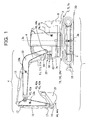
- FIG. 1 is a schematic side view showing a working machine according to the first embodiment.
- an upperstructure 3 is rotatably mounted on an undercarriage 2, and the upperstructure 3 is rotatably driven by a swing motor 7.
- an operator's cab 4 and an engine 5 are mounted on the upperstructure 3.
- a counterweight 8 is mounted on a rear part of the upperstructure 3.
- a controller 60 that controls the entire working machine 1 is arranged to make up the working machine 1.
- a boom 10 is arranged pivotally up and down via a fulcrum 40 as a joint, and on a free end of the boom 10, an arm 12 is pivotally arranged via a fulcrum 41 as a joint. Further, on a free end of the arm 12, a bucket 23 is pivotally arranged as a working attachment via a fulcrum 42 as a joint. It is to be noted that the boom 10 and arm 12 make up a front working mechanism 6.
- An boom cylinder 11 is an actuator for driving the boom 10 such that it pivots about the fulcrum 40, and is connected to the upperstructure 3 and the boom 10.
- An arm cylinder 13 is an actuator for driving the arm 12 such that it pivots about the fulcrum 41, and is connected to the boom 10 and the arm 12.
- a working attachment 15 is an actuator for driving the bucket 23 such that it pivots about the fulcrum 42, and is connected to the bucket 23 via a link 16 and also to the arm 12 via a link 17. It is to be noted that the bucket 23 can be replaced to another working attachment such as a grapple, cutter or breaker.
- the upperstructure 3 is provided with the operator' s cab 4 for an operator who operates the working machine 1.
- a control device 50 for inputting operating instructions from the operator to various drive actuators, a display (display means) 61 for displaying a support polygon, ZMP coordinates and the like, which will be described subsequently herein, a warning device (warning means) 63 for producing a tipping warning sound or the like with respect to the working machine 1, a user setting input device 55 for allowing the operator to perform various settings, and so on.
- a blade 18 is arranged pivotally up and down on a front wall of the undercarriage 2, and the blade 18 is driven by a blade cylinder 19.
- the upperstructure 3 is provided with a posture sensor 3b for detecting a tilt of the below-described machine reference coordinate system relative to a world coordinate system that uses, as a Z-axis, a direction opposite to the gravity.
- the posture sensor 3b is, for example, a tilt angle sensor, and by detecting a tilt angle of the upperstructure 3, detects a tilt of the machine reference coordinate system relative to the world coordinate system.
- a swing angle sensor 3s is arranged to detect a swing angle of the upperstructure 3 relative to the undercarriage 2.
- a boom angle sensor (angle sensor) 40a is arranged to measure a pivot angle of the boom 10.
- an arm angle sensor (angle sensor) 41a is arranged to measure a pivot angle of the arm 12.
- a bucket angle sensor 42a is arranged to measure a pivot angle of the bucket 23.
- an undercarriage acceleration sensor 2a, upperstructure acceleration sensor 3a, boom acceleration sensor 10a and arm acceleration sensor 12a are arranged, respectively.
- a pin 43 which connects the arm 12 and the bucket 23 together, and a pin 44, which connects the link 16 and the bucket 23 together, are provided with pin force sensors 43a,44a, respectively.
- pin force sensors 43a,44a strain gauges are inserted, for example, in cylindrical bores. By measuring strains produced on the strain gauges, the magnitudes and directions of forces (external forces) applied to the pins 43,44 are detected.
- the swing motor 7, which rotates the upperstructure 3, is provided with swing motor pressure sensors 7i and 7o for detecting a suction-side pressure and delivery-side pressure of a hydraulic pressure that is driving the swing motor 7.
- the blade cylinder 19 is provided with blade cylinder pressure sensors 7i and 7o for detecting a suction-side pressure and delivery-side pressure of a hydraulic pressure that is driving the blade cylinder 19.
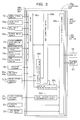
- FIG. 2 is a schematic configuration diagram of a controller which the working machine 1 provided with.
- the controller 60 is provided with an input unit 60h in which signals are inputted from the respective sensors arranged at the corresponding parts of the working machine 1, a computing unit 60g for receiving the signals inputted in the input unit 60h and performing predetermined computations, and an output unit 60i for receiving output signals from the computing unit 60g and outputting safety information and tipping warning information on the working machine 1 (see FIG. 1 ).
- the display 61 displays the safety information and tipping warning information on the working machine 1
- the warning device 63 produces a warning on tipping.
- the computing unit 60g is constructed of an unillustrated microcomputer, an unillustrated peripheral circuitry, and so on.
- the microcomputer is provided with CPU (Central Processing Unit) and a memory unit including ROM (Read Only Memory), RAM (Random Access Memory), a flash memory and the like.
- the computing unit 60g operates according to a program stored, for example, in the ROM.
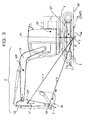
- FIG. 3 is a schematic side view showing a ZMP-computing model of the working machine having the controller.
- a world coordinate system (O-XYZ) and a machine reference coordinate system (O-XYZ) are set as shown in FIG. 3 .
- the world coordinate system uses the direction of the gravity as a reference, and also uses, as a Z-axis, a direction opposite to the gravity.
- the machine reference coordinate system uses the undercarriage 2 as a reference.
- the machine reference coordinate system is assumed to belong to the undercarriage 2. As shown in FIG. 3 , the origin of the machine reference coordinate system is set at a point O which is located on the center line 3c of rotation of the upperstructure 3 and is in contact with a ground surface 30, and an X-axis, Y-axis and Z-axis are set in a longitudinal direction, lateral direction and vertical direction of the undercarriage 2, respectively.
- a lumped mass model in which respective structural members are assumed to have their masses lumping at their centers of gravity as shown in FIG. 3 is used as a model for computing a ZMP 70 in view of the simplicity of assembly.
- Mass points 2P,3P,10P,12P of the undercarriage 2, upperstructure 3, boom 10 and arm 12 are set at the barycentric positions of the respective structural members, and the masses at the respective mass points are assumed to be m2, m3, m10, m12, respectively.
- the position vectors at the respective mass points are assumed to be r2, r3, r10, r12, and the acceleration vectors at the respective mass points are assumed to be r"2,r"3,r"10,r”12, respectively.
- the setting method of mass points is not limited to the above-described one and, for example, positions at which masses lump (the engine 5, counterweight 8 and the like, which are shown in FIG. 1 ) may be added.
- an external force is applied to a tip of the bucket 23.
- the gravity and inertia force of the bucket 23 and external forces applied in the direction of the X-axis and the direction of the Y-axis to the bucket 23 are all calculated as external vectors F43 and F44 applied to the pin 43 and pin 44 to compute the coordinates of the ZMP.
- the position vectors at the pin 43 and pin 44 as acting points of external forces are assumed to be s43, s44.
- an external force applied in the lateral direction (in the direction of the Y-axis) to the bucket 23 is assumed to be F46
- the position vector at an acting point 46 of the lateral external force is assumed to be s46.
- a ZMP Zero Moment Point
- a ZMP stability discrimination criterion is based on the d'Alembert's principle. The concept of ZMP and ZMP stability discrimination criterion are described in Miomir Vukobratovic: "LEGGED LOCOMOTION ROBOTS” (translated into Japanese by Ichiro KATO: “HOKOU ROBOTTO To JINKOU NO ASHI (LEGGED LOCOMOTON ROBOTS AND ARTIFICIAL LEGS)" by Nikkan Kogyo Shimbun-sha).
- a point where moments in the directions of pitch axis and roll axis become zero, therefore, exists on one of sides of or inside a support polygon formed by connecting points of contact between the working machine 1 and the ground surface 30 such that no concave shape is allowed.
- the ZMP exists in the support polygon and the force acting from the working machine 1 on the ground surface 30 is in a pressing direction against the ground surface 30, in other words, the ground reaction force is positive, the working machine 1 can be considered to be in stable contact with the ground.
- the stability is higher as the ZMP is closer to the center of the polygon, and the working machine 1 can perform work without tipping when the ZMP is located inside the support polygon.
- the working machine 1 has a potential problem that it may start tipping. It is, therefore, possible to determine the stability by comparing the ZMP with the support polygon formed by the working machine 1 and the ground surface 30.
- each vector is a three-dimensional vector having X-component, Y-component and Z-component.
- the first termin the left side of the above equation (1) represents the sum of moments (radii: r i -r zmp ) about the ZMP 70 (see FIG. 3 ), which are produced by acceleration components (which include gravitational accelerations) applied at the respective mass points m i .
- the second term in the left side of the above equation (1) represents the sum of external moments M j acting on the working machine 1.
- the third term in the left side of the above equation (1) represents the sum of moments (radii: sk-r zmp ) about the ZMP 70, which are produced by external forces F k (the acting point of the k th external force vector F k is represented by sk).
- the equation (1) describes that the sum of the moments (radii: r i -r zmp ) about the ZMP 70, which are produced by the acceleration components (which include gravitational accelerations) applied at the respective mass points m i , the sum of external moments M j , and the sum of the moments (radii: sk-r zmp ) about the ZMP 70, which are produced by the external forces F k (the acting point of the k th external vector F k is represented by sk), are balancing.
- the ZMP 70 on the ground surface 30 can be calculated by the ZMP equation expressed as equation (1).
- the ZMP coincides with a projected point of the static center of gravity on the ground surface.
- the ZMP can, accordingly, be dealt with as the projected point of the center of gravity with a dynamic state and a static state being taken in consideration, and the use of the ZMP as an index makes it possible to commonly deal with both cases where an object is at rest and where the object undergoing motion.
- the computing unit 60g illustrated in FIG. 2 is primarily provided with function blocks of a linkage computing means 60a, ZMP computing means 60b, stability computing means 60c, blade ground-contact determination means 60d, jack-up determination means 60e, and lateral external force computing means 60f.
- the individual function blocks that make up the computing unit 60g can be realized by a software logic that the respective functions are incorporated in the program for driving the computing unit 60g.
- Detection values of the posture sensor 3b, swing angle sensor 3s, boom angle sensor 40a, arm angle sensor 41a, bucket angle sensor 42a, undercarriage acceleration sensor 2a, upperstructure acceleration sensor 3a, boom acceleration sensor 10a, arm acceleration sensor 12a and pin force sensors 43a, 44a, which are shown in FIG. 1 and FIG. 2 and are arranged at the various parts of the working machine 1, are fed to the linkage computing means 60a.
- kinematic calculations are sequentially performed by using a value of the posture sensor 3b shown in FIG. 1 and arranged on the upperstructure 3 and detection values of the swing angle sensor 3s, boom angle sensor 40a, arm angle sensor 41a and bucket angle sensor 42a shown in FIG. 1 and arranged at the various parts of the working machine 1.
- the acceleration vectors r"2,r"3,r"10,r”12 at the respective mass points as calculated from the results of detection at the undercarriage acceleration sensor 2a, upperstructure acceleration sensor 3a, boom acceleration sensor 10a and arm acceleration sensor 12a, the position vectors s43, s44, s46 at the acting point 46 of lateral external force, and the respective external force vectors F43, F44, F46 acting on the pins 43,44 are then converted to values based on the machine reference coordinate system (O-XYZ).
- the coordinates of the ZMP 70 as illustrated in FIG. 4(a) or 4(b) are calculated by using the position vectors, acceleration vectors and external force vectors at the respective mass points, said vectors having been converted to the machine reference coordinate system.
- r zmpy ⁇ i m i ⁇ r iy ⁇ r iz ⁇ - r iz ⁇ r iy ⁇ - ⁇ k s ky ⁇ F kz - s kz ⁇ F ky ⁇ i m i r iz ⁇ - ⁇ k F kz
- m is the mass at each mass point 2P, 3P, 10P or 12P shown in FIG. 3 , and the masses m2, m3, m10, m12 at the respective mass points are substituted for m.
- r" is an acceleration at each mass point, and the accelerations r"2, r"3, r"10, r"12 are substituted for r".
- s indicates a position vector at each one of the pins 43,44 as the acting points of external forces and the acting point 46 of lateral external force on the bucket 23, and s43,s44,s46 are substituted for s.
- F represents an external force vector applied to each one of the pins 43, 44 as the acting points of external forces and the acting point of lateral external force on the bucket 23, and F43,F44,F46 are substituted for F.
- the ZMP computing means 60b can calculate the coordinates of the ZMP 70 by using the detection values of the respective sensors arranged at the various parts of the working machine 1.
- the stability computing means 60c next performs a discrimination of the stability of the working machine 1 on the basis of the coordinates of the ZMP 70 (X-coordinate: 70x, Y-coordinate: 70y) as calculated by the ZMP computing means 60b.
- the ZMP 70 exists inside a support polygon L formed by ground contact points between the working machine 1 and the ground surface 30 as described above, the working machine 1 shown in FIG. 1 can perform work without tipping over.
- the stability computing means 60c in the first embodiment calculates the support polygon L formed by the working machine 1 and ground surface 30 as illustrated in FIG. 4(a) or 4(b) , and with respect to the support polygon L, sets a normal region J where the possibility of tipping is sufficiently low and a tipping warning region N where the possibility of tipping is higher.
- the stability computing means 60c When the coordinates of the ZMP 70 are in the normal region J, the stability computing means 60c outputs information on the stability to the display 61. When the coordinates of the ZMP 70 are in the tipping warning region N, on the other hand, the stability computing means 60c outputs information on the stability and a tipping warning to the display 61 and warning device 63, respectively.
- the operator can become aware of the possibility of tipping before the ZMP 70 reaches any one of the sides of the support polygon L.
- FIGS. 4(a) and 4(b) are diagrams, each of which illustrates the support polygon L and ZMP 70.
- FIG. 4 (a) diagrammatically illustrates one example of the support polygon, in which the undercarriage is located upright on the ground surface.
- FIG. 4(b) diagrammatically illustrates another example of the support polygon, in which the undercarriage has been jacked up by the front working mechanism.
- FIGS. 4 (a) and 4 (b) each illustrate an image displayed on the display 61 (see FIG. 1 ) arranged in the operator's cab 4 (see FIG. 1 ) and the surrounding double lines indicate a frame of the display 61.
- the support polygon L is substantially the same as the planar shape of the undercarriage 2.
- the support polygon L therefore, becomes rectangular as illustrated in FIG. 4(a) .
- the support polygon L is in a quadrilateral shape having, as a front boundary, a line connecting central points of left and right sprockets 32, as a rear boundary, a line connecting central points of left and right idlers 33, and as left and right boundaries, right and left outer side edges of respective track links.
- the front and rear boundaries can be the ground contact points of frontmost lower rollers 34 and the ground contact points of rearmost lower rollers 34, respectively.
- the working machine 1 comes into contact with the ground surface 30 at a free end of the front working mechanism 6 and a rear part of the undercarriage 2 (when the front working mechanism 6 jacks up in front of the undercarriage 2) so that the support polygon L becomes such a polygon as illustrated in FIG. 4(b) .
- the calculation of the support polygon L is performed based on the state of ground contact of the working machine 1 with reference to the result of determination by the blade ground-contact determination means 60d or jack-up determination means 60e.
- a boundary K between the normal region J and the tipping warning region N is set inside the support polygon L. Described specifically, the boundary K is set as a polygon contracted toward a central point at a ratio determined according to a safety factor, or as a polygon moved inward by a length determined according to the safety factor.
- the safety factor may be a desired value set beforehand (for example, 80%) or may be a value to be changed depending on the proficiency level of the operator who operates the working machine 1, work details, road surface, surrounding circumstances and the like. In this case, it may be contemplated to automatically set the safety factor from information given beforehand, output values of various sensors, or the like, or to allow an operator or work supervisor to set the safety factor as desired by using the user setting input device 55.
- safety factor may be changed during work depending on the operating conditions of the working machine 1 or safety factors of different values may be used for the front, rear, left and right boundaries, respectively.
- the ZMP 70 is prone to move toward the downhill side on an inclined surface so that tipping tends to occur more easily toward the downhill side than the uphill side.
- the tipping warning region N is, therefore, set to become wider on the downhill side depending on the inclination as illustrated in FIG. 6(a) . It may be contemplated to use, as the inclination, an input by the operator or a detection value of the posture sensor 3b.
- tipping in a direction other than the direction in which the front working mechanism 6 exists tends to result in a more serious accident compared with tipping in the direction toward the front working mechanism 6. It is, therefore, desired to set the tipping warning region N such that in view of the direction of the front working mechanism 6, it becomes wider in directions other than the direction of the front working mechanism 6 as illustrated in FIG. 6 (b) . It is to be noted that the direction of the front working mechanism 6 relative to the support polygon L can be detected by the swing angle sensor 3s.
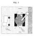
- FIG. 7 An example of the setting of the tipping warning region N, which takes into consideration the operating conditions and surrounding circumstances, is illustrated in FIG. 7 .
- the example of FIG. 7 assumes a situation, in which the working machine 1 is parking headed uphill on a gently sloping ground, there are workers at the rear and left rear of the working machine 1, a truck exists on the left side, and a ditch exists on the right side of the working machine 1.
- the tipping warning region N is set broader in the direction where the ditch exists, and further, the tipping warning region N is set still broader in the directions where the workers and truck exist, both compared with the front side where no hazard exists.
- the tipping warning region N is also set to become broader on the downhill side (rear side) where tipping tends to occur.
- a method for setting the tipping warning region N as described above it is contemplated to manually change the setting as needed by the operator or work supervisor or to use a GPS, map information, a CAD drawing of the work, or the like.
- the use of the above-described information makes it possible to automatically discriminate a direction where tipping tends to occur or a direction where a damage is large if tipped and to automatically change the boundary K between the normal region J and the tipping warning region N such that the tipping warning region N becomes broader in such directions.
- tipping warning region N As a setting method of the tipping warning region N, it may be contemplated to recognize the details of ongoing work and to change the size and/or shape of the tipping warning region N depending on the work details.
- Tipping warning regions N which conform to characteristic operation patterns in plural kinds of work such as suspending work, digging work, demolishing work and traveling and also to their respective work details, are set and stored beforehand.
- a lever stroke sensor 51 is arranged to detect input command quantities for the respective drive actuators 11,13,15, and from the posture of the front working mechanism and an external force on the bucket as calculated at the ZMP computing means and a record of detection values of the lever stroke sensor 51, the closest one is chosen from the operation patterns set beforehand and the corresponding tipping warning region N is outputted.
- the safety factor may be changed depending on the intensity of motion of the working machine 1. While the working machine 1 is undergoing motion, the effect of the moment term under inertia force in the ZMP equation represented by the equation (1) becomes large, and the displacement of the ZMP 70 increases. In other words, when the working machine 1 is undergoing some motion, the ZMP 70 is easier to reach the support polygon L and the possibility of tipping is higher. It can, therefore, be configured such that by changing the size of the tipping warning zone N in conformity to the operating conditions of the working machine 1, a tipping warning can be promptly outputted when the working machine 1 is intensely moving.
- the sum of momenta at respective mass points are used as an index for evaluating the intensity of the operating conditions of the working machine 1. Described specifically, this sum is the total of the absolute values of products of the masses m2, m3, m10, m12 at the respective mass points 2P, 3P, 10P, 12P set as shown in FIG. 3 and the velocities r' 2, r' 3, r' 10, r' 12 at the respective mass points as calculated from the integrals of values of the respective acceleration sensors (undercarriage acceleration sensor 2a, upperstructure acceleration sensor 3a, boom acceleration sensor 10a, arm acceleration sensor 12a) shown in FIG. 1 or the derivatives of values of the respective angle sensors shown in FIG. 1 , and can be expressed by the following equation: Equation 5 ⁇ i m i ⁇ r i ⁇
- the size of the tipping warning region N is then determined. Described more specifically, when the sum of momenta as expressed by the equation (5) is 0, the boundary K between the normal region J and the tipping warning region K is set at a largest position, while it is set at a smallest position when the sum of the momenta is largest. In other words, the normal region J becomes largest when the sum of momenta is 0 and, when the sum of momenta is largest, the tipping warning region N becomes large and the normal region J becomes small.
- the maximum value of each momentum is calculated from the corresponding cylinder speed governed by the performance of the working machine 1.
- the largest position of the boundary K is assumed to be a position obtained by moving the support polygon L inward by an amount equivalent to a safety allowance set in view of an accuracy of measurement and the reaction lag of the operator.
- the smallest position of the boundary K is assumed to be a position obtained by moving the support polygon L inward such that sufficient safety is assured even when the working machine 1 is moving at a maximum speed.
- an interpolation is made with straight lines such that the boundary K is set inward little by little as the sum of momenta of the working machine increases. Curves formed of combinations of parabolas and circular arcs may, however, be used for the interpolation between the largest position and smallest position of the boundary K.
- the sum of kinetic energies at respective mass points may be used. Described specifically, this sum is the total of the products of the masses m2, m3, m10, m12 and the squares of velocities r'2,r'3,r'10,r'12 at the respective mass points 2P,3P,10P,12P shown in FIG. 3 , and can be expressed by the following equation: Equation 6 ⁇ i m i ⁇ r i ⁇ ⁇ 2
- the determination of stability which uses the ZMP 70, in the first embodiment can be performed by assignment operation on the equation (3) or (4) and a comparison between the results of the assignment operation and a predetermined region. Therefore, the setting of a complex model is not needed, and in any operation, the computation of stability is feasible by performing a similar computation. It is, accordingly, possible to bring about an excellent effect that moment-by-moment computation and determination of stability are feasible irrespective of the type of operation.
- the external force F46 applied in the Y-axis to the bucket 23 is calculated.
- the acting point of an external force in the direction of the Y-axis is assumed to be the acting point 46 of lateral external force.
- the external force vector F46 is calculated at the lateral external force computing means 60f by using pressure values of a hydraulic pressure, which is driving the swing motor 7, as detected by the swing motor pressure sensors 7i and 7o arranged at the swing motor 7.
- the lateral external force computing means 60f uses such a model as shown in FIG. 5.
- FIG. 5 is a top plan view showing modeling of the upperstructure in the first embodiment.
- a swing torque Tz3 applied to the upperstructure 3 is calculated from a difference in hydraulic pressure between a suction-side hydraulic pressure detected by the swing motor pressure sensor 7i and a delivery-side hydraulic pressure detected by the swing motor pressure sensor 70, said pressure sensors 7i and 7o being arranged at the swing motor 7.
- the swing angle is used to convert Fy46 to a value based on the machine reference coordinate system (O-XYZ).
- the lateral external force vector F46 calculated as described above acts on the acting point 46 of external force on the bucket 23 as shown in FIG. 3 , whereby a moment is produced.
- the blade ground-contact determination means 60d performs a determination as to whether or not the blade 18 is in contact with the ground surface 30.
- the undercarriage 2 of the working machine 1 according to the first embodiment has the blade 18, and depending on the state of ground contact of the blade 18, the shape of the support polygon L changes. Described more specifically, when the blade 18 is in contact with the ground, the support polygon L takes a shape including a bottom part of the blade as shown in FIG. 8 so that the support polygon L is changed in shape to become larger. To determine the stability more accurately, it is, therefore, necessary to change the shape of the support polygon L to be used in the setting of the tipping warning region N at the stability computing means 60b.
- the blade ground-contact determination means 60d determines the state of ground contact of the blade 18 by using values Pb1, Pb2 of the blade cylinder pressure sensors 19i, 19o which measure the suction-side pressure and delivery-side pressure of the hydraulic pressure that is driving the blade cylinder 19.
- a threshold value Pb3 is set such that it is greater than a pressure required to drive the blade 18 under unloaded conditions but is smaller than a pressure required to jack up the working machine 1.
- Pb1-Pb2 is greater than the threshold value Pb3
- the blade 18 is determined to be in contact with the ground surface 30 and a signal is fed to the stability computing means 60c.
- the signal from the blade ground-contact determination means 60d is received to change the shape of the support polygon L such that it becomes larger as illustrated in FIG. 8 .
- the ground contact points between the working machine 1 and the ground surface 30 have changed so that the shape of the support polygon L changes. Described specifically, the support polygon L changes from the rectangular shape illustrated in FIG. 4(a) to a polygonal shape that, as shown in FIG. 4(b) , is formed by two end points on a side, where the undercarriage 2 is in contact with the ground, and a ground contact point of the bucket 23.
- the jack-up determination means 60e determines a jacked-up state and sends a signal to the stability computing means 60c. It is to be noted that in a jack-up operation, which part of the undercarriage 2 is lifted up differs depending on the ground contact position of the bucket 23.
- FIGS. 9(a) through 9(d) are diagrams illustrating relationships between directions of the front working mechanism 6 and support polygons L.
- the front of the undercarriage 2 is lifted up so that the support polygon L takes a polygonal shape formed by the rear end points of the undercarriage 2 and the ground contact point of the bucket 23.
- the rear of the undercarriage 2 is lifted up so that the support polygon L takes a polygonal shape formed by the front end points of the undercarriage 2 and the ground contact point of the bucket 23.
- the right side or left side of the undercarriage 2 is lifted up so that the support polygon L takes a polygonal shape formed by the end points of the left side or right side of the undercarriage 2 and the ground contact point of the bucket 23.
- the ZMP 70 exists on a front left (upper) side relative to a line segment connecting the farthermost end point (the left rear end point of the undercarriage 2) from the central point of the ground contact point of the bucket 23 (the central bucket ground-contact point) out of the end points of the undercarriage 2 and the central bucket ground-contact point as illustrated in FIGS. 9(c) and 9(d) , the left front end point comes into contact with the ground so that the right side of the undercarriage 2 is lifted up. Therefore, the support polygon L takes a polygonal shape formed by the left end points of the undercarriage 2 and the ground contact point of the bucket 23.
- the support polygon L takes a polygonal shape formed by the front end points of the undercarriage 2 and the ground contact point of the bucket 23.
- the jack-up determination means 60e another determination is made, in addition to the determination of a jacked-up state, as to which part of the undercarriage 2 is lifted up and which part of the undercarriage 2 comes into contact with the ground when the jacked-up state is determined, the shape of the support polygon L is calculated, and a signal is fed to the stability computing means 60c.
- kinematic calculations are sequentially performed to calculate the ground contact point of the bucket 23.
- the central bucket ground-contact point is calculated, and among the end points of the undercarriage 2, the end point farthermost from the central bucket ground-contact point will be referred to as "the first ground contact end point”.
- a line segment connecting the first ground contact end point and the central bucket ground-contact point and the ZMP 70 are compared with each other, and of the two end points located adjacent to the first ground contact end point, the end point on the side where the ZMP 70 exists will be referred to as "the second ground contact end point".
- a polygonal shape formed by connecting the first and second, ground contact end points and the ground contact point of the bucket 23 will be used as the support polygon L.
- the ground contact end points of the undercarriage 2 may be configured to calculate a tilt of the undercarriage 2 by using detection values of the posture sensor 3b and swing angle sensor 3s and to select, as the ground contact points, two downhill-side end points out of the end points of the undercarriage 2.
- the signal is received from the jack-up determination means 60e to change the shape of the support polygon L.
- the working machine 1 As also shown in FIG. 1 , the working machine 1 according to the first embodiment is provided with the display 61 and warning device 63.
- the display (display means) 61 is a device comprised of a cathode ray tube, liquid crystal panel or the like, is arranged in the operator's cab (see FIG. 1 ), and displays the support polygon L, tipping warning region N, ZMP coordinates (see FIG. 4 ) and the like, all of which have been computed by the controller 60.
- the display 61 may be configured to display a sign of a tipping warning.
- the operator By displaying the stability and tipping warning on the display 61 arranged in the operator's cab 4 as described above, the operator is always made aware of any possibility of tipping so that work of high safety can be performed.
- the display 61 may be configured to also serve as the user setting input device 55 through which the operator can perform the setting of a tipping warning region and a warning method.
- the display 61 should be provided with an input means such as a touch panel and should perform displaying a setting input icon.
- the warning device (warning means) 63 is also arranged in the operator's cab 4.
- the warning device 63 is a device, for example, a buzzer or the like, and can produce a warning sound.
- the ZMP 70 is found to exist in the tipping warning region N (see FIG. 4 ) as a result of a computation at the controller 60, the warning device produces a warning such as a warning sound by a control from the stability computing means 60c (see FIG. 2 ).
- the mass of the operator and fuel such as gas oil at standard constant values and to include them in the mass of the upperstructure 3.
- fuel such as gas oil
- it may be configured to change the mass and center of gravity of the upperstructure 3 according to the mass of the operator and/or the mass of fuel.
- Concerning the mass of the operator it may be configured to automatically measure the mass by arranging a weighing scale or the like in the operator's cab or to allow the operator to input the mass through the user setting input device 55.
- the mass of the fuel on the other hand, it may be contemplated to use, for example, a method that calculates the mass by multiplying a residual quantity of the fuel, which can be detected by a fuel gauge, with the specific gravity of the fuel.
- the description was made under the assumption that the operator sits in the operator's cab 4 arranged on the working machine 1 and performs the control of the working machine 1.
- the control of the working machine 1 is performed by a remote control that makes use of wireless transmission.
- a remote control it is difficult to accurately grasp the posture of the working machine, the inclination of a road surface and the like compared with the time that the operator sits in the operator's cab. Further, it is difficult even for a skilled operator to get a sensory grasp of the safety of the working machine.
- the display of stability information and the warning for the operator can, therefore, bring about still better advantageous effects at the time of a remote control.
- control lever In the remote-controlled working machine, the control lever is generally arranged at a control site for the operator other than on the working machine 1.
- the display device and warning device can also be arranged at the site where the operator performs controls.
- a display for the work supervisor can be arranged at a site other than on the working machine 1 in addition to the display for the operator, and by performing a data transfer through wireless transmission, the conditions of the working machine 1 can be displayed.
- the showing on the display for the supervisor may be the same as that for the operator, or other information may be additionally displayed.
- the above-described first embodiment makes it possible, no matter whichever operation the working machine 1 is performing, to calculate moment by moment the dynamic stability including an inertia force of the front working mechanism and an external force and to provide the operator with information on the safety without delay. As a result, it is possible to reduce the possibility of tipping of the working machine by an unreasonably aggressive operation and to provide a working machine of high safety.
- a motion such as a contact of the blade with the ground or a jack-up, that the state of contact between the working machine and the ground surface changes and by changing the tipping warning region, the safety can be accurately determined to enhance the stability even when the state of contact with the ground changes.
- a relative angle is detected by the swing angle sensor 3s in the first embodiment, it may be configured to detect absolute azimuths of the upperstructure 3 and undercarriage 2 by using geomagnetic sensors, a GPS or the like and to calculate a relative swing angle based on a difference between the absolute azimuths.
- the adoption of such a configuration makes it possible to practice the present invention even when it is difficult to arrange the swing angle sensor 3s.
- the boom angle sensor 40a and arm angle sensor 41a are used for the detection of a posture of the front working mechanism 6. It may, however, be configured to use a tilt angle sensor instead of these angle sensors. The adoption of such a configuration makes it possible to practice the present invention even when it is difficult to arrange angle sensors at the fulcrums 40 and 41.
- the upperstructure acceleration sensor 3a, boom acceleration sensor 10a and arm acceleration sensor 12a are used to calculate accelerations at the respective mass points 3P, 10P, 12P shown in FIG. 3 .
- these accelerations may be determined by perform second order differential on values of the angle sensors without arranging these acceleration sensors.
- a rotational acceleration of the upperstructure 3 it can be determined by performing second order differential on a rotational angle of the upperstructure as detected by the swing angle sensor 3s.
- the posture sensor 3b is arranged on the upperstructure 3. It may, however, be possible to adopt a configuration that the posture sensor 3 is arranged on the undercarriage 2. The adoption of such a configuration makes it possible to calculate an inclination of the machine reference coordinate system relative to the world coordinate system without using the detection value of the swing angle sensor 3s.
- the posture sensor 3b on the upperstructure 3 is used for the detection of an inclination of the road surface. It may, however, be possible to adopt a configuration without the posture sensor 3b when an acceleration sensor capable of measuring a direct current component (gravity) is used as the undercarriage acceleration sensor 2a. In such a case, the working machine can be constructed with a more economical and simpler configuration because the number of sensors to be arranged decreases and signals to be fed to the controller 60 become fewer.
- an acceleration sensor capable of measuring a direct current component gravitation
- the working machine can be constructed with a more economical and simpler configuration because the number of sensors to be arranged is reduced and signals to be fed to the controller 60 become fewer.
- the ZMP70 can now be calculated under the assumption that the machine reference coordinate system is always horizontal relative to the world coordinate system.
- an acceleration of the undercarriage 2 may be configured to estimate the acceleration from an acceleration of the upperstructure 3 and a swing angle detected by the swing angle sensor 3s, and therefore, to omit the undercarriage acceleration sensor 2a which would otherwise be adapted to detect the acceleration of the undercarriage 2.
- the ZMP 70 can now be calculated under the assumption that the acceleration r"2 of the undercarriage 2 has only a gravity component.
- the use of a slip ring, wireless transmission or the like is needed to transmit a detection value of a sensor to the controller 60 when the sensor is arranged on the undercarriage 2.
- a configuration is adopted without the undercarriage acceleration sensor 2a and blade cylinder pressure sensors 19i, 19o as described above, it is no longer needed to transmit information by using a slip ring, wireless transmission or the like, thereby making it possible to adopt a simpler configuration of higher reliability.
- the working machine can be constructed with a more economical and simpler configuration.
- the ZMP 70 can now be calculated under the assumption that the acceleration r"3 of the upperstructure 3 has only a gravity component.
- a moment MI which includes an external force on the bucket and the own weight of the front working mechanism, is calculated from detection values of the pressure sensors 11a, 11b arranged at the boom cylinder, and a own weight moment Moc of the front working mechanism is calculated from detection values of the respective angle sensors for the boom, arm and bucket and the respective center-of-gravity parameters of the boom, arm and bucket.
- the external force on the bucket is then calculated from the difference between the moments MI and Moc and the distance from the center of rotation to the bucket.
- the working machine 1 When the working machine 1 is provided, for example, with an unillustrated cutter as a working attachment and primarily performs only cutting work, no substantial external force is applied to the front working mechanism 6 during the work because the cutting work is performed using the internal force of the cutter. In a case like this that there is no risk of a deterioration in stability by an external force during work, the configuration may be adopted without the pin force sensors 43a,44a that would otherwise be needed to detect an external force applied to the pins 43,44 (see FIG. 1 ).
- an acceleration sensor is also arranged on the working attachment, and based on a gravity applied to working machine 1 and an inertia force applied to the working attachment, a ZMP computation can be performed.
- the configuration can be provided more economically.
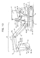
- FIG. 10 is a schematic side view showing a working machine according to the second embodiment
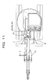
- FIG. 11 is a top plan view showing an upperstructure in the second embodiment by modeling it.
- similar elements of structure as the corresponding ones in the first embodiment are identified by like signs, and their description is omitted.
- the second embodiment is different from the first embodiment in that a swing mechanism, which performs a horizontal swing, is arranged between an upperstructure 3 and a boom 10. A description will hereinafter be made primarily about this difference from the first embodiment.
- the upperstructure 3 is rotatably mounted on an undercarriage 2, and the upperstructure 3 is driven by a swing motor 7.
- an operator' s cab 4, a counterweight 8 and the like are mounted on the upperstructure 3.
- a swing post 24 is arranged pivotally at a fulcrum 45.
- the swing post 24 is horizontally swung by a swing cylinder 25 (see FIG. 11 ) connected to the upperstructure 3 and the swing post 24.
- the working machine 1a is also provided with a controller 80 that controls the entire working machine 1a.
- the boom 10 On the swing post 24, the boom 10 is arranged pivotally up and down at a fulcrum 40, and on the boom 10, an arm 12 is arranged pivotally at a fulcrum 41. Further, on the arm 12, a bucket 23 is arranged pivotally at a fulcrum 42. Like the first embodiment, the boom 10 and arm 12 make up a front working mechanism 6.
- a boom cylinder 11 is arranged to drive the boom 10, and is connected to the swing post 24 and boom 10.
- the arm 12 is driven by an arm cylinder 13, and the bucket 23 is driven by a working attachment cylinder 15.
- the upperstructure 3 is provided with the operator' s cab 4 for an operator who operates the working machine 1a.
- Arranged in the operator's cab 4 are, as in the first embodiment, a control device 50, a display 61, and a warning device 63.
- the working machine 1a is provided, as in the first embodiment, with a swing angle sensor 3s, posture sensor 3b, boom angle sensor 40a, arm angle sensor 41a, bucket angle sensor 42a, undercarriage acceleration sensor 2a, upperstructure acceleration sensor 3a, boom acceleration sensor 10a, and arm acceleration sensor 12a.
- a swing angle sensor 45a is also arranged at the fulcrum 45 between the upperstructure 3 and the swing post 24 to detect a rotational angle of the swing post 24.
- swing pressure sensors 25i and 25o are arranged on a suction side and delivery side of a hydraulic pressure, which is driving the swing post cylinder 25, to detect a suction-side pressure and delivery-side pressure.
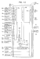
- FIG. 12 is a schematic configuration diagram of a controller arranged in the working machine according to the second embodiment.
- function blocks of the controller 80 as illustrated in FIG. 10 like function blocks as the corresponding ones of the controller 60 in the first embodiment are identified by like signs, and their description is omitted.
- a swing torque Tz45 applied about the fulcrum 45 of the swing post 24 is calculated from a difference in pressure between the suction-side pressure and the delivery-side pressure detected by the swing pressure sensors 25i and 25o arranged at the swing cylinder 25.
- a linkage computation with detection values of the swing angle sensor 45a, boom angle sensor 40a, arm angle sensor 41a and bucket angle sensor 42a (see FIG. 10 ) which the frontworkingmechanism 6 is provided with, a distance vector 1 from the fulcrum 45 of the swing post 24 to an acting point 46 of lateral external force on the bucket 23 is next calculated.
- position vectors r2, r3, r10, r12 at the respective mass points, acceleration vectors r"2,r"3,r”10,r”12 at the respective mass points, position vectors s43, s44 at the respective acting points of external forces, and respective external force vectors F43, F44, F46 are then converted to values based on the machine reference coordinate system (O-XYZ).
- a stability computing means 60c also calculates ZMP coordinates by using the results of the linkage computation and performs a discrimination of stability in a similar manner as in the first embodiment.
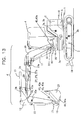
- FIG. 13 is a schematic side view showing a working machine according to the third embodiment
- FIG. 14 is a top plan view showing an upperstructure in the third embodiment by modeling it.
- similar elements of structure as the corresponding ones in the first embodiment are identified by like signs, and their description is omitted.
- the third embodiment is different from the first embodiment in that it has, as a horizontal pivot mechanism, an offset mechanism which allows the front working mechanism 6 to undergo a horizontal translation at its front part beyond an arm 12. A description will hereinafter be made primarily about this difference from the first embodiment.
- the working machine 1b is primarily constructed of an undercarriage 2, an upperstructure 3, and a swing motor 7 for driving the upperstructure 3.
- an operator's cab 4, a counterweight 8 and the like are mounted on the upperstructure 3.
- the working machine 1b is also provided with a controller 90 that controls the entire working machine 1b.
- the front working mechanism 6 is provided with a boom (lower boom) 10 arranged pivotally up and down on the upperstructure 3, an upper boom 26 arranged on a free end side of the boom 10, an arm support 28 arranged on a free end s ide of the upper boom 2 6, the arm 12 pivotally arranged on a free end side of the arm support 28, a bucket 23 pivotally attached to a free end side of the arm 12, a link rod 29 connecting between the boom 10 and the arm support 28, a boom cylinder 11 for driving the boom 10, an arm cylinder 13 for driving the arm 12, a working attachment cylinder 15 for driving the bucket 23, and an offset cylinder 27 for horizontally pivoting the upper boom 26.
- a boom (lower boom) 10 arranged pivotally up and down on the upperstructure 3, an upper boom 26 arranged on a free end side of the boom 10, an arm support 28 arranged on a free end s ide of the upper boom 2 6, the arm 12 pivotally arranged on a free end side of the arm support 28, a bucket 23 pivotally attached to a free
- the front working mechanism 6 changes pivot angles at a fulcrum 47 between the boom 10 and the upper boom 26 and at a fulcrum 48 between the upper boom 26 and the arm support 28 by way of the offset cylinder 27, so that the upper boom 26 is brought into a state that it has undergone a horizontal translation (offset) relative to the lower boom 10.
- the working machine 1b according to the third embodiment can perform, for example, digging work of trenches or the like alongside a road by actuating the cylinders for the boom 10, the arm 12 and a working attachment such as the bucket 23 with the front working attachment 6 being kept in an offset state as described above.
- the upperstructure 3 is provided with the operator's cab 4 for an operator who operates the working machine 1b.
- a control device 50 Arranged in the operator's cab 4 are, as in the first embodiment, a control device 50, a display 61, and a warning device 63.
- the working machine 1b is provided, as in the first embodiment, with a swing angle sensor 3s, posture sensor 3b, boom angle sensor 40a, arm angle sensor 41a, bucket angle sensor 42a, undercarriage acceleration sensor 2a, upperstructure acceleration sensor 3a, boom acceleration sensor 10a, and arm acceleration sensor 12a.
- an offset angle sensor 48a is also arranged, as shown in FIG. 14 , at the offset fulcrum 48 to detect a pivot angle at the fulcrum 48.
- the offset cylinder 27 is provided with offset pressure sensors 27i and 27o to detect a suction-side pressure and delivery-side pressure of a hydraulic pressure that is driving the offset cylinder 27.
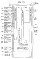
- FIG. 15 is a schematic configuration diagram of a controller arranged in the working machine according to the third embodiment.
- function blocks of the controller 90 as illustrated in FIG. 15 similar function blocks as the corresponding ones of the controller 60 in the first embodiment are identified by like signs, and their description is omitted accordingly.
- a swing torque Tz48 applied about the offset fulcrum 48 is calculated from a difference in pressure between the suction-side pressure and delivery-side pressure detected by the offset pressure sensors 27i and 27o arranged at the offset cylinder 27.
- a distance vector l from the offset fulcrum 48 to an acting point 46 of lateral external force on the bucket 23 is next calculated.
- a stability computing means 60c uses the results of the linkage computation to calculate ZMP coordinates and performs a discrimination of stability in a similar manner as in the first embodiment.
- various sensors can also be changed or omitted as in the first embodiment. Further, a configuration which is not provided with the upperstructure 3 may also be adopted.
- this embodiment makes it possible to calculate moment by moment the dynamic stability including an inertia force of the front working mechanism and an external force during an operation and to provide the operator with information on the safety without delay. It is, therefore, possible to reduce the possibility of tipping of the working machine by an unreasonably aggressive operation and to provide a working machine of high safety.
- the safety can be accurately determined to enhance the stability even when the state of contact with the ground changes.
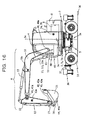
- FIG. 16 is a schematic side view showing a working machine according to the fourth embodiment
- FIGS. 17(a) to 17(c) are diagrams showing examples of a support polygon in the fourth embodiment.
- similar elements of structure as the corresponding ones in the first embodiment are identified by like signs, and their description is omitted.
- the fourth embodiment is different from the first embodiment in that it has wheels at a travel base of an undercarriage 2. A description will hereinafter be made primarily about this difference from the first embodiment.
- the working machine 1c is primarily constructed of the undercarriage 2, an upperstructure 3, and a swing motor 7 for driving the upperstructure 3.
- an operator's cab 4, a counterweight 8 and the like are mounted on the upperstructure 3.
- the working machine 1c is also provided with a controller 90 that controls the entire working machine 1c.
- the undercarriage 2 is constructed of wheels 35, stabilizers 36, stabilizer cylinders 37, and frames, axles and the like which support these wheels, stabilizers and stabilizer cylinders.
- the stabilizers 36 are driven by the stabilizer cylinders 37, respectively.
- the construction of the front working mechanism 6 is similar to that in the first embodiment.
- a control device 50 Arranged in the operator' s cab 4 are, as in the first embodiment, a control device 50, a display 61, and a warning device 63.
- the working machine 1c is provided, as in the first embodiment, with a swing angle sensor 3s, posture sensor 3b, boom angle sensor 40a, arm angle sensor 41a, bucket angle sensor 42a, undercarriage acceleration sensor 2a, upperstructure acceleration sensor 3a, boom acceleration sensor 10a, and arm acceleration sensor 12a.
- the basic configuration of the controller 60 is similar to that in the first embodiment as illustrated in FIG. 2 .
- function blocks of the controller 60 similar function blocks as the corresponding ones in the first embodiment are identified by like signs, and their description is omitted accordingly.
- a stability computing means 60c performs, as in the first embodiment, a discrimination of stability on the basis of the coordinates of a ZMP 70 as calculated by a ZMP computing means 60b.
- the stability computing means 60c calculates a support polygon L formed by the working machine 1 and a ground surface 30, and with respect to the support polygon L, sets a normal region J where the possibility of tipping is sufficiently low and a tipping warning region N where the possibility of tipping is higher.
- the stability computing means 60c outputs information on the stability to the display 61.
- the stability computing means 60c outputs information on the stability and a tipping warning to the display 61 and warning device 63, respectively.
- FIGS. 17(a) to 17(c) are diagrams illustrating examples of a support polygon L in the fourth embodiment.
- the support polygon L takes a quadrilateral shape formed by connecting the ground contact points of the front, rear, left and right stabilizers 36.
- the support polygon L takes a quadrilateral shape formed by connecting ground contact points of the stabilizers, which are located in ground contact areas of the stabilizers at positions right below a center line of a pivotal motion.
- the support polygon L takes a quadrilateral shape formed by connecting points, which are located in ground contact areas of the stabilizers and are farthermost from centers of the ground contact areas.
- a quadrilateral shape formed by connecting ground contact points of the front, rear, left and right wheels 35 as illustrated in FIG. 17(b) is used as the support polygon L.
- the support polygon L is similar to that of FIG. 17 (b) .
- the support polygon L takes a quadrilateral shape formed by connecting ground contact points of the ground-contacting stabilizers 36 and ground contact points of the wheels 35 in the directions where the front, rear, left or right ones of the stabilizers 36 are not in contact with the ground.
- the support polygon L is similar to that of FIG. 3(c) .
- whether or not the stabilizers 36 are in contact with the ground may be changed based on setting by the operator, or the stability computing means 60c may be configured to determine it automatically.
- the stability computing means 60c may be configured to determine it automatically.
- a method for automatically determining whether or not the stabilizers 36 are in contact with the ground it is possible to contemplate a method that provides each stabilizer or each stabilizer cylinder 37 with a posture sensor and determines from the posture of the stabilizer whether or not the stabilizer is in contact with the ground or a method that provides each stabilizer cylinder 37 with pressure sensors and determines from detected pressure values whether or not the corresponding stabilizer is in contact with the ground.
- a boundary K between the normal region J and the tipping warning region N is set inside the support polygon L.
- the boundary K is determined as in the first embodiment.
- the first to fourth embodiments according to the present invention have been described above. In each of these embodiments, however, it is possible to change the conditions for stability discretion corresponding to the operating conditions of the working machine and to discriminate the stability of the working machine on the basis of the changed conditions for stability discretion. It is, therefore, possible to bring about the excellent advantageous effect that the operator can confirm the stability moment by moment corresponding to the operating conditions of the working machine and work of high safety can be performed.
- the description was made taking, as the working machine 1, the hydraulic excavator by way of example.
- the present invention can be applied to any working machine insofar as it has a travel base and a front working mechanism.
- the lumpedmass model was used as a model for computing the ZMP 70.
- the working machine may be configured to practice the present invention based on another modeling format such as a rigid model.
- the working machine 1 may be without the upperstructure 3.
- the front working mechanism 6 is configured to be directly arranged on the undercarriage 2.
- the working machine is configured such that the posture sensor 3b is arranged on the undercarriage 2 and neither the swing angle sensor 3s nor the upperstructure 3a is arranged.
Landscapes
- Engineering & Computer Science (AREA)
- Mining & Mineral Resources (AREA)
- Civil Engineering (AREA)
- General Engineering & Computer Science (AREA)
- Structural Engineering (AREA)
- Mechanical Engineering (AREA)
- Component Parts Of Construction Machinery (AREA)
- Operation Control Of Excavators (AREA)
Applications Claiming Priority (2)
| Application Number | Priority Date | Filing Date | Title |
|---|---|---|---|
| JP2009240511 | 2009-10-19 | ||
| PCT/JP2010/068356 WO2011049079A1 (ja) | 2009-10-19 | 2010-10-19 | 作業機械 |
Publications (2)
| Publication Number | Publication Date |
|---|---|
| EP2492404A1 true EP2492404A1 (de) | 2012-08-29 |
| EP2492404A4 EP2492404A4 (de) | 2015-12-09 |
Family
ID=43900303
Family Applications (1)
| Application Number | Title | Priority Date | Filing Date |
|---|---|---|---|
| EP10824928.5A Withdrawn EP2492404A4 (de) | 2009-10-19 | 2010-10-19 | Betriebsmaschine |
Country Status (6)
| Country | Link |
|---|---|
| US (1) | US8768580B2 (de) |
| EP (1) | EP2492404A4 (de) |
| JP (1) | JP5491516B2 (de) |
| KR (1) | KR101755739B1 (de) |
| CN (1) | CN102575457B (de) |
| WO (1) | WO2011049079A1 (de) |
Cited By (6)
| Publication number | Priority date | Publication date | Assignee | Title |
|---|---|---|---|---|
| GB2493946A (en) * | 2011-08-24 | 2013-02-27 | James Fraser Dunphy | Crane monitoring system |
| WO2015071520A1 (es) * | 2013-11-14 | 2015-05-21 | Empresa De Transformacion Agraria, S.A. (Tragsa) | Sistema y método para control de estabilidad en maquinaria pesada |
| EP2578757A4 (de) * | 2010-05-24 | 2017-04-05 | Hitachi Construction Machinery Co., Ltd. | Sicherheitsvorrichtung für eine arbeitsmaschine |
| KR20210021945A (ko) * | 2018-06-19 | 2021-03-02 | 스미토모 겐키 가부시키가이샤 | 굴삭기, 정보처리장치 |
| EP3789542A4 (de) * | 2019-03-29 | 2022-01-19 | Hitachi Construction Machinery Co., Ltd. | Arbeitsmaschine |
| CN116220127A (zh) * | 2023-02-22 | 2023-06-06 | 长沙仁毅机械制造有限公司 | 一种高空移动式挖机 |
Families Citing this family (59)
| Publication number | Priority date | Publication date | Assignee | Title |
|---|---|---|---|---|
| GB2485770A (en) * | 2010-11-23 | 2012-05-30 | Flintec Uk Ltd | Lifting Device with Distributed-Sensing Scale |
| US9440357B2 (en) * | 2011-05-02 | 2016-09-13 | John Hu | System for stabilization control of mobile robotics |
| US9348327B2 (en) * | 2011-06-10 | 2016-05-24 | Hitachi Construction Machinery Co., Ltd. | Work machine |
| CN103857851B (zh) * | 2011-10-19 | 2016-03-09 | 住友重机械工业株式会社 | 回转作业机械及回转作业机械的控制方法 |
| USD686642S1 (en) * | 2012-05-10 | 2013-07-23 | Hitachi Construction Machinery Co., Ltd. | Swing post for a construction machine |
| JP5851037B2 (ja) * | 2012-07-20 | 2016-02-03 | 日立建機株式会社 | 作業機械 |
| JP6111562B2 (ja) * | 2012-08-31 | 2017-04-12 | セイコーエプソン株式会社 | ロボット |
| US8909437B2 (en) * | 2012-10-17 | 2014-12-09 | Caterpillar Inc. | Payload Estimation system |
| JP5969379B2 (ja) * | 2012-12-21 | 2016-08-17 | 住友建機株式会社 | ショベル及びショベル制御方法 |
| CN103255786A (zh) * | 2013-04-09 | 2013-08-21 | 常熟建工建设集团有限公司苏州分公司 | 一种新型单斗液压挖掘机的工作装置 |
| US9115581B2 (en) | 2013-07-09 | 2015-08-25 | Harnischfeger Technologies, Inc. | System and method of vector drive control for a mining machine |
| KR101531872B1 (ko) * | 2013-10-10 | 2015-06-26 | 재단법인대구경북과학기술원 | 이동장치의 배토판에 가해지는 외부 모멘트의 산출방법 |
| DE102013221302A1 (de) * | 2013-10-21 | 2015-04-23 | Mts Maschinentechnik Schrode Ag | Baumaschine |
| KR101459028B1 (ko) * | 2014-04-25 | 2014-11-07 | 이호 | 아웃트리거를 장착한 크레인의 전도 방지 장치 |
| KR101747018B1 (ko) * | 2014-06-04 | 2017-06-14 | 가부시키가이샤 고마쓰 세이사쿠쇼 | 작업 기계의 자세 연산 장치, 작업 기계 및 작업 기계의 자세 연산 방법 |
| WO2015193394A1 (en) * | 2014-06-18 | 2015-12-23 | Cnh Industrial Italia S.P.A. | A safety hydraulic circuit |
| EP3021178B1 (de) * | 2014-11-14 | 2020-02-19 | Caterpillar Inc. | System mit Radarvorrichtung zur Unterstützung eines Benutzers einer Maschine mit einem Körper und einem Werkzeug |
| EP3020868B1 (de) * | 2014-11-14 | 2020-11-04 | Caterpillar Inc. | Maschine mit einem Maschinenkörper und einem hinsichtlich des Körpers beweglichen Werkzeug mit einem System zur Unterstützung eines Benutzers der Maschine |
| US10120369B2 (en) | 2015-01-06 | 2018-11-06 | Joy Global Surface Mining Inc | Controlling a digging attachment along a path or trajectory |
| DE102015102368A1 (de) * | 2015-02-19 | 2016-08-25 | Schwing Gmbh | Positionsregelung Mastspitze |
| JP6545498B2 (ja) * | 2015-03-26 | 2019-07-17 | 住友建機株式会社 | ショベル |
| JP2017008659A (ja) * | 2015-06-25 | 2017-01-12 | Kyb株式会社 | Zmp演算装置およびzmp演算方法 |
| CA2943939C (en) * | 2015-09-30 | 2021-10-19 | Deere & Company | Stability warning and control intervention system for a forestry vehicle |
| JP6306552B2 (ja) * | 2015-10-13 | 2018-04-04 | 株式会社タダノ | 遠隔操作装置、及び案内システム |
| JP7084722B2 (ja) * | 2015-12-18 | 2022-06-15 | 住友重機械工業株式会社 | ショベルおよびその制御方法 |
| DE102016000353A1 (de) * | 2016-01-14 | 2017-07-20 | Liebherr-Components Biberach Gmbh | Kran-, Baumaschinen- oder Flurförderzeug-Simulator |
| CN108603360B (zh) * | 2016-03-31 | 2022-10-21 | 住友重机械工业株式会社 | 挖土机 |
| KR102463068B1 (ko) * | 2016-09-30 | 2022-11-02 | 스미토모 겐키 가부시키가이샤 | 쇼벨 |
| CN106829813A (zh) * | 2017-01-19 | 2017-06-13 | 徐工消防安全装备有限公司 | 一种臂架式高空作业车行走动平衡控制装置及方法 |
| EP3584120B1 (de) * | 2017-02-17 | 2021-04-14 | Sumitomo Heavy Industries, Ltd. | System zur überwachung der umgebung für arbeitsmaschinen |
| WO2018179577A1 (ja) * | 2017-03-29 | 2018-10-04 | 日立建機株式会社 | 作業機械 |
| JP6789880B2 (ja) * | 2017-05-16 | 2020-11-25 | 株式会社クボタ | 作業機の状態管理システム |
| JP6824830B2 (ja) * | 2017-06-19 | 2021-02-03 | 株式会社神戸製鋼所 | 転倒防止装置及び作業機械 |
| JP7289787B2 (ja) * | 2017-09-07 | 2023-06-12 | 住友建機株式会社 | ショベル |
| JP6918654B2 (ja) * | 2017-09-11 | 2021-08-11 | 日立建機株式会社 | 作業車両 |
| JP6824856B2 (ja) * | 2017-09-29 | 2021-02-03 | 株式会社小松製作所 | 表示制御装置および表示制御方法 |
| CN111148878B (zh) * | 2018-01-10 | 2023-08-04 | 住友建机株式会社 | 挖土机及挖土机的管理系统 |
| WO2019151335A1 (ja) * | 2018-01-30 | 2019-08-08 | 住友建機株式会社 | ショベル及びショベルの管理システム |
| CN108411974A (zh) * | 2018-02-01 | 2018-08-17 | 三峡大学 | 一种挖掘机安全装载量自动防倾覆报警系统 |
| JP6877385B2 (ja) * | 2018-04-23 | 2021-05-26 | 日立建機株式会社 | 作業機械 |
| GB2573304A (en) * | 2018-05-01 | 2019-11-06 | Caterpillar Inc | A method of operating a machine comprising am implement |
| US10767348B2 (en) * | 2018-07-30 | 2020-09-08 | Deere & Company | Machine stability detection and control |
| JP7265323B2 (ja) * | 2018-07-31 | 2023-04-26 | 株式会社小松製作所 | 作業機械を制御するためのシステム及び方法 |
| WO2020049623A1 (ja) * | 2018-09-03 | 2020-03-12 | 日立建機株式会社 | 作業機械 |
| JP7222775B2 (ja) * | 2019-03-26 | 2023-02-15 | 日立建機株式会社 | 作業機械 |
| KR102077493B1 (ko) * | 2019-06-13 | 2020-04-08 | 재단법인 한국전자기계융합기술원 | 굴삭기 전복 감지 시스템 |
| CN110395229A (zh) * | 2019-07-29 | 2019-11-01 | 北京航天发射技术研究所 | 一种基于远程无线控制的调平支撑装置和调平方法 |
| JP7264796B2 (ja) * | 2019-11-21 | 2023-04-25 | 株式会社小松製作所 | 転倒リスク提示装置および転倒リスク提示方法 |
| CN110908318B (zh) * | 2019-12-17 | 2020-10-13 | 三一重机有限公司 | 一种挖掘机倾倒的控制方法、控制装置及可读存储介质 |
| CN111042261A (zh) * | 2019-12-30 | 2020-04-21 | 三一重机有限公司 | 挖掘机动态称重方法及系统 |
| US11421402B2 (en) * | 2020-02-05 | 2022-08-23 | Caterpillar Paving Products Inc. | Operation-based object detection for a work machine |
| US11918535B2 (en) * | 2020-04-13 | 2024-03-05 | Toyota Research Institute, Inc. | Wearable exoskeleton |
| KR20220030098A (ko) * | 2020-09-02 | 2022-03-10 | 현대두산인프라코어(주) | 자율 작업 굴착기 및 그의 동작 방법 |
| CN112499533A (zh) * | 2020-10-30 | 2021-03-16 | 徐州海伦哲特种车辆有限公司 | 一种臂架类作业车动态幅度限制方法 |
| JP7706901B2 (ja) | 2021-03-08 | 2025-07-14 | 株式会社小松製作所 | 転倒評価システム、転倒評価方法及び作業機械 |
| JP7375260B2 (ja) * | 2021-04-19 | 2023-11-07 | 日立建機株式会社 | 作業機械 |
| JP2023070617A (ja) * | 2021-11-09 | 2023-05-19 | コベルコ建機株式会社 | 管理システム |
| KR20240150804A (ko) * | 2022-03-31 | 2024-10-16 | 히다찌 겐끼 가부시키가이샤 | 휠식 건설 기계 |
| EP4715129A1 (de) * | 2024-09-24 | 2026-03-25 | Volvo Truck Corporation | Kippminderung für fahrzeuge |
Family Cites Families (17)
| Publication number | Priority date | Publication date | Assignee | Title |
|---|---|---|---|---|
| US4284987A (en) * | 1979-09-07 | 1981-08-18 | The United States Of America As Represented By The Secretary Of Agriculture | Slope stability warning device for articulated tractors |
| GB8612424D0 (en) * | 1986-05-22 | 1986-07-02 | Arcubos Systems Ltd | Weight sensing device |
| JP2871105B2 (ja) | 1990-12-03 | 1999-03-17 | 油谷重工株式会社 | 解体作業機の安全装置 |
| JPH05319785A (ja) | 1991-09-06 | 1993-12-03 | Yotaro Hatamura | 建設機械の姿勢制御システム |
| US5160055A (en) * | 1991-10-02 | 1992-11-03 | Jlg Industries, Inc. | Load moment indicator system |
| JP3194611B2 (ja) * | 1992-01-29 | 2001-07-30 | 株式会社小松製作所 | 油圧ショベルの転倒防止装置 |
| JPH07180192A (ja) | 1993-12-24 | 1995-07-18 | Hitachi Constr Mach Co Ltd | 油圧シヨベルの転倒防止装置 |
| JPH09105155A (ja) * | 1995-10-11 | 1997-04-22 | Hitachi Constr Mach Co Ltd | 建設機械の姿勢安定度算出装置 |
| US6991119B2 (en) * | 2002-03-18 | 2006-01-31 | Jlg Industries, Inc. | Measurement system and method for assessing lift vehicle stability |
| GB2412902B (en) * | 2004-04-07 | 2008-04-09 | Linde Ag | Industrial truck having increased static or quasi-static tipping stability |
| JP2006150567A (ja) | 2004-12-01 | 2006-06-15 | Toyota Motor Corp | ロボットの安定化制御装置 |
| JP4142692B2 (ja) * | 2006-02-07 | 2008-09-03 | 株式会社竹内製作所 | 作業車のバッテリ配置構造 |
| JP4824492B2 (ja) | 2006-07-07 | 2011-11-30 | 富士通株式会社 | 移動型ロボット |
| US7870919B2 (en) * | 2007-02-28 | 2011-01-18 | Crown Equipment Corporation | Materials handling vehicle |
| US8086370B2 (en) * | 2007-10-05 | 2011-12-27 | Nacco | Load controlled stabilizer system |
| CN201158831Y (zh) * | 2008-02-26 | 2008-12-03 | 山东交通学院 | 一种道路与铁路两栖挖掘机 |
| GB2471134B (en) * | 2009-06-19 | 2012-10-10 | Bamford Excavators Ltd | Speed sensitive longitudinal load moment control of a working machine |
-
2010
- 2010-10-19 JP JP2011537258A patent/JP5491516B2/ja active Active
- 2010-10-19 KR KR1020127009975A patent/KR101755739B1/ko not_active Expired - Fee Related
- 2010-10-19 CN CN201080047042.0A patent/CN102575457B/zh not_active Expired - Fee Related
- 2010-10-19 US US13/502,598 patent/US8768580B2/en active Active
- 2010-10-19 WO PCT/JP2010/068356 patent/WO2011049079A1/ja not_active Ceased
- 2010-10-19 EP EP10824928.5A patent/EP2492404A4/de not_active Withdrawn
Non-Patent Citations (1)
| Title |
|---|
| See references of WO2011049079A1 * |
Cited By (10)
| Publication number | Priority date | Publication date | Assignee | Title |
|---|---|---|---|---|
| EP2578757A4 (de) * | 2010-05-24 | 2017-04-05 | Hitachi Construction Machinery Co., Ltd. | Sicherheitsvorrichtung für eine arbeitsmaschine |
| GB2493946A (en) * | 2011-08-24 | 2013-02-27 | James Fraser Dunphy | Crane monitoring system |
| GB2493946B (en) * | 2011-08-24 | 2017-07-19 | Fraser Dunphy James | Crane monitoring system |
| WO2015071520A1 (es) * | 2013-11-14 | 2015-05-21 | Empresa De Transformacion Agraria, S.A. (Tragsa) | Sistema y método para control de estabilidad en maquinaria pesada |
| KR20210021945A (ko) * | 2018-06-19 | 2021-03-02 | 스미토모 겐키 가부시키가이샤 | 굴삭기, 정보처리장치 |
| EP3812517A4 (de) * | 2018-06-19 | 2021-09-15 | Sumitomo (S.H.I.) Construction Machinery Co., Ltd. | Bagger und informationsverarbeitungsvorrichtung |
| US11959253B2 (en) | 2018-06-19 | 2024-04-16 | Sumitomo Construction Machinery Co., Ltd. | Excavator and information processing apparatus |
| KR102708684B1 (ko) | 2018-06-19 | 2024-09-20 | 스미토모 겐키 가부시키가이샤 | 굴삭기, 정보처리장치 |
| EP3789542A4 (de) * | 2019-03-29 | 2022-01-19 | Hitachi Construction Machinery Co., Ltd. | Arbeitsmaschine |
| CN116220127A (zh) * | 2023-02-22 | 2023-06-06 | 长沙仁毅机械制造有限公司 | 一种高空移动式挖机 |
Also Published As
| Publication number | Publication date |
|---|---|
| KR20120095875A (ko) | 2012-08-29 |
| CN102575457B (zh) | 2014-12-17 |
| JPWO2011049079A1 (ja) | 2013-03-14 |
| WO2011049079A1 (ja) | 2011-04-28 |
| CN102575457A (zh) | 2012-07-11 |
| JP5491516B2 (ja) | 2014-05-14 |
| US8768580B2 (en) | 2014-07-01 |
| EP2492404A4 (de) | 2015-12-09 |
| US20120232763A1 (en) | 2012-09-13 |
| KR101755739B1 (ko) | 2017-07-19 |
Similar Documents
| Publication | Publication Date | Title |
|---|---|---|
| US8768580B2 (en) | Operation machine | |
| EP2578757B1 (de) | Arbeitsmaschine mit einer sicherheitsvorrichtung | |
| KR101934017B1 (ko) | 작업 기계 | |
| US9745727B2 (en) | System and method for controlling stability in heavy machinery | |
| CN109642417B (zh) | 作业机械 | |
| CA2125375C (en) | Tactile control for automated bucket loading | |
| CN103046606B (zh) | 工程机械设备、可移动式配重系统及控制方法 | |
| JP5887405B2 (ja) | 作業機械の応力演算システム | |
| CN201040850Y (zh) | 液压挖掘机防倾翻装置 | |
| CN116562438A (zh) | 一种挖掘机斜坡作业的倾翻预测方法及倾翻预警系统 | |
| JP2021147772A (ja) | 作業機械及び作業機械の疲労検出方法 | |
| JP2010185204A (ja) | 杭打機の安定度測定装置及び方法 | |
| KR101776819B1 (ko) | 굴삭기 전도 상태 판별 방법 | |
| US20240151007A1 (en) | Fall evaluation system, fall evaluation method, and work machine | |
| Dudziński et al. | Innovative system for monitoring the tip over stability of mobile excavating machines on a tracked undercarriage | |
| KR20250107619A (ko) | 건설기계 장비의 전도방지 시스템 | |
| KR20250107620A (ko) | 건설기계 장비의 전도방지 시스템 | |
| KR100244099B1 (ko) | 건설 기계의 인양 하중 검출방법(hethod for detecting hoist load in construction machine) | |
| CN121729541A (zh) | 作业机械 |
Legal Events
| Date | Code | Title | Description |
|---|---|---|---|
| PUAI | Public reference made under article 153(3) epc to a published international application that has entered the european phase |
Free format text: ORIGINAL CODE: 0009012 |
|
| 17P | Request for examination filed |
Effective date: 20120521 |
|
| AK | Designated contracting states |
Kind code of ref document: A1 Designated state(s): AL AT BE BG CH CY CZ DE DK EE ES FI FR GB GR HR HU IE IS IT LI LT LU LV MC MK MT NL NO PL PT RO RS SE SI SK SM TR |
|
| DAX | Request for extension of the european patent (deleted) | ||
| RA4 | Supplementary search report drawn up and despatched (corrected) |
Effective date: 20151110 |
|
| RIC1 | Information provided on ipc code assigned before grant |
Ipc: E02F 9/24 20060101ALI20151104BHEP Ipc: E02F 9/26 20060101ALI20151104BHEP Ipc: B66C 23/90 20060101ALI20151104BHEP Ipc: E02F 9/20 20060101AFI20151104BHEP |
|
| 17Q | First examination report despatched |
Effective date: 20160929 |
|
| STAA | Information on the status of an ep patent application or granted ep patent |
Free format text: STATUS: EXAMINATION IS IN PROGRESS |
|
| STAA | Information on the status of an ep patent application or granted ep patent |
Free format text: STATUS: THE APPLICATION IS DEEMED TO BE WITHDRAWN |
|
| 18D | Application deemed to be withdrawn |
Effective date: 20180822 |