EP2487736B1 - Batteries pour outils électriques et procédés d'assemblage de bornes de batteries dans des boîtiers de batterie - Google Patents
Batteries pour outils électriques et procédés d'assemblage de bornes de batteries dans des boîtiers de batterie Download PDFInfo
- Publication number
- EP2487736B1 EP2487736B1 EP12155207.9A EP12155207A EP2487736B1 EP 2487736 B1 EP2487736 B1 EP 2487736B1 EP 12155207 A EP12155207 A EP 12155207A EP 2487736 B1 EP2487736 B1 EP 2487736B1
- Authority
- EP
- European Patent Office
- Prior art keywords
- battery
- terminals
- circuit board
- electric circuit
- mounting portion
- Prior art date
- Legal status (The legal status is an assumption and is not a legal conclusion. Google has not performed a legal analysis and makes no representation as to the accuracy of the status listed.)
- Active
Links
- 238000000034 method Methods 0.000 title claims description 11
- 239000000463 material Substances 0.000 claims description 13
- 238000000465 moulding Methods 0.000 claims description 9
- 238000003780 insertion Methods 0.000 claims description 8
- 230000037431 insertion Effects 0.000 claims description 8
- 239000011347 resin Substances 0.000 claims description 6
- 229920005989 resin Polymers 0.000 claims description 6
- XLYOFNOQVPJJNP-UHFFFAOYSA-N water Substances O XLYOFNOQVPJJNP-UHFFFAOYSA-N 0.000 description 9
- 210000000078 claw Anatomy 0.000 description 8
- 230000004048 modification Effects 0.000 description 3
- 238000012986 modification Methods 0.000 description 3
- 239000000853 adhesive Substances 0.000 description 2
- 230000001070 adhesive effect Effects 0.000 description 2
- 239000002253 acid Substances 0.000 description 1
- 239000004020 conductor Substances 0.000 description 1
- 238000010292 electrical insulation Methods 0.000 description 1
- 238000004519 manufacturing process Methods 0.000 description 1
- 230000002093 peripheral effect Effects 0.000 description 1
Images


Classifications
-
- H—ELECTRICITY
- H01—ELECTRIC ELEMENTS
- H01M—PROCESSES OR MEANS, e.g. BATTERIES, FOR THE DIRECT CONVERSION OF CHEMICAL ENERGY INTO ELECTRICAL ENERGY
- H01M50/00—Constructional details or processes of manufacture of the non-active parts of electrochemical cells other than fuel cells, e.g. hybrid cells
- H01M50/20—Mountings; Secondary casings or frames; Racks, modules or packs; Suspension devices; Shock absorbers; Transport or carrying devices; Holders
- H01M50/247—Mountings; Secondary casings or frames; Racks, modules or packs; Suspension devices; Shock absorbers; Transport or carrying devices; Holders specially adapted for portable devices, e.g. mobile phones, computers, hand tools or pacemakers
-
- H—ELECTRICITY
- H01—ELECTRIC ELEMENTS
- H01M—PROCESSES OR MEANS, e.g. BATTERIES, FOR THE DIRECT CONVERSION OF CHEMICAL ENERGY INTO ELECTRICAL ENERGY
- H01M50/00—Constructional details or processes of manufacture of the non-active parts of electrochemical cells other than fuel cells, e.g. hybrid cells
- H01M50/20—Mountings; Secondary casings or frames; Racks, modules or packs; Suspension devices; Shock absorbers; Transport or carrying devices; Holders
- H01M50/204—Racks, modules or packs for multiple batteries or multiple cells
- H01M50/207—Racks, modules or packs for multiple batteries or multiple cells characterised by their shape
- H01M50/213—Racks, modules or packs for multiple batteries or multiple cells characterised by their shape adapted for cells having curved cross-section, e.g. round or elliptic
-
- H—ELECTRICITY
- H01—ELECTRIC ELEMENTS
- H01M—PROCESSES OR MEANS, e.g. BATTERIES, FOR THE DIRECT CONVERSION OF CHEMICAL ENERGY INTO ELECTRICAL ENERGY
- H01M50/00—Constructional details or processes of manufacture of the non-active parts of electrochemical cells other than fuel cells, e.g. hybrid cells
- H01M50/20—Mountings; Secondary casings or frames; Racks, modules or packs; Suspension devices; Shock absorbers; Transport or carrying devices; Holders
- H01M50/218—Mountings; Secondary casings or frames; Racks, modules or packs; Suspension devices; Shock absorbers; Transport or carrying devices; Holders characterised by the material
- H01M50/22—Mountings; Secondary casings or frames; Racks, modules or packs; Suspension devices; Shock absorbers; Transport or carrying devices; Holders characterised by the material of the casings or racks
- H01M50/227—Organic material
-
- H—ELECTRICITY
- H01—ELECTRIC ELEMENTS
- H01M—PROCESSES OR MEANS, e.g. BATTERIES, FOR THE DIRECT CONVERSION OF CHEMICAL ENERGY INTO ELECTRICAL ENERGY
- H01M50/00—Constructional details or processes of manufacture of the non-active parts of electrochemical cells other than fuel cells, e.g. hybrid cells
- H01M50/20—Mountings; Secondary casings or frames; Racks, modules or packs; Suspension devices; Shock absorbers; Transport or carrying devices; Holders
- H01M50/244—Secondary casings; Racks; Suspension devices; Carrying devices; Holders characterised by their mounting method
-
- H—ELECTRICITY
- H01—ELECTRIC ELEMENTS
- H01M—PROCESSES OR MEANS, e.g. BATTERIES, FOR THE DIRECT CONVERSION OF CHEMICAL ENERGY INTO ELECTRICAL ENERGY
- H01M50/00—Constructional details or processes of manufacture of the non-active parts of electrochemical cells other than fuel cells, e.g. hybrid cells
- H01M50/20—Mountings; Secondary casings or frames; Racks, modules or packs; Suspension devices; Shock absorbers; Transport or carrying devices; Holders
- H01M50/262—Mountings; Secondary casings or frames; Racks, modules or packs; Suspension devices; Shock absorbers; Transport or carrying devices; Holders with fastening means, e.g. locks
-
- H—ELECTRICITY
- H01—ELECTRIC ELEMENTS
- H01M—PROCESSES OR MEANS, e.g. BATTERIES, FOR THE DIRECT CONVERSION OF CHEMICAL ENERGY INTO ELECTRICAL ENERGY
- H01M50/00—Constructional details or processes of manufacture of the non-active parts of electrochemical cells other than fuel cells, e.g. hybrid cells
- H01M50/20—Mountings; Secondary casings or frames; Racks, modules or packs; Suspension devices; Shock absorbers; Transport or carrying devices; Holders
- H01M50/271—Lids or covers for the racks or secondary casings
-
- H—ELECTRICITY
- H01—ELECTRIC ELEMENTS
- H01M—PROCESSES OR MEANS, e.g. BATTERIES, FOR THE DIRECT CONVERSION OF CHEMICAL ENERGY INTO ELECTRICAL ENERGY
- H01M50/00—Constructional details or processes of manufacture of the non-active parts of electrochemical cells other than fuel cells, e.g. hybrid cells
- H01M50/20—Mountings; Secondary casings or frames; Racks, modules or packs; Suspension devices; Shock absorbers; Transport or carrying devices; Holders
- H01M50/284—Mountings; Secondary casings or frames; Racks, modules or packs; Suspension devices; Shock absorbers; Transport or carrying devices; Holders with incorporated circuit boards, e.g. printed circuit boards [PCB]
-
- H—ELECTRICITY
- H01—ELECTRIC ELEMENTS
- H01M—PROCESSES OR MEANS, e.g. BATTERIES, FOR THE DIRECT CONVERSION OF CHEMICAL ENERGY INTO ELECTRICAL ENERGY
- H01M50/00—Constructional details or processes of manufacture of the non-active parts of electrochemical cells other than fuel cells, e.g. hybrid cells
- H01M50/50—Current conducting connections for cells or batteries
- H01M50/543—Terminals
- H01M50/547—Terminals characterised by the disposition of the terminals on the cells
- H01M50/548—Terminals characterised by the disposition of the terminals on the cells on opposite sides of the cell
-
- H—ELECTRICITY
- H01—ELECTRIC ELEMENTS
- H01M—PROCESSES OR MEANS, e.g. BATTERIES, FOR THE DIRECT CONVERSION OF CHEMICAL ENERGY INTO ELECTRICAL ENERGY
- H01M50/00—Constructional details or processes of manufacture of the non-active parts of electrochemical cells other than fuel cells, e.g. hybrid cells
- H01M50/50—Current conducting connections for cells or batteries
- H01M50/543—Terminals
- H01M50/552—Terminals characterised by their shape
- H01M50/559—Terminals adapted for cells having curved cross-section, e.g. round, elliptic or button cells
-
- H—ELECTRICITY
- H01—ELECTRIC ELEMENTS
- H01M—PROCESSES OR MEANS, e.g. BATTERIES, FOR THE DIRECT CONVERSION OF CHEMICAL ENERGY INTO ELECTRICAL ENERGY
- H01M10/00—Secondary cells; Manufacture thereof
- H01M10/42—Methods or arrangements for servicing or maintenance of secondary cells or secondary half-cells
- H01M10/46—Accumulators structurally combined with charging apparatus
-
- Y—GENERAL TAGGING OF NEW TECHNOLOGICAL DEVELOPMENTS; GENERAL TAGGING OF CROSS-SECTIONAL TECHNOLOGIES SPANNING OVER SEVERAL SECTIONS OF THE IPC; TECHNICAL SUBJECTS COVERED BY FORMER USPC CROSS-REFERENCE ART COLLECTIONS [XRACs] AND DIGESTS
- Y02—TECHNOLOGIES OR APPLICATIONS FOR MITIGATION OR ADAPTATION AGAINST CLIMATE CHANGE
- Y02E—REDUCTION OF GREENHOUSE GAS [GHG] EMISSIONS, RELATED TO ENERGY GENERATION, TRANSMISSION OR DISTRIBUTION
- Y02E60/00—Enabling technologies; Technologies with a potential or indirect contribution to GHG emissions mitigation
- Y02E60/10—Energy storage using batteries
-
- Y—GENERAL TAGGING OF NEW TECHNOLOGICAL DEVELOPMENTS; GENERAL TAGGING OF CROSS-SECTIONAL TECHNOLOGIES SPANNING OVER SEVERAL SECTIONS OF THE IPC; TECHNICAL SUBJECTS COVERED BY FORMER USPC CROSS-REFERENCE ART COLLECTIONS [XRACs] AND DIGESTS
- Y02—TECHNOLOGIES OR APPLICATIONS FOR MITIGATION OR ADAPTATION AGAINST CLIMATE CHANGE
- Y02P—CLIMATE CHANGE MITIGATION TECHNOLOGIES IN THE PRODUCTION OR PROCESSING OF GOODS
- Y02P70/00—Climate change mitigation technologies in the production process for final industrial or consumer products
- Y02P70/50—Manufacturing or production processes characterised by the final manufactured product
-
- Y—GENERAL TAGGING OF NEW TECHNOLOGICAL DEVELOPMENTS; GENERAL TAGGING OF CROSS-SECTIONAL TECHNOLOGIES SPANNING OVER SEVERAL SECTIONS OF THE IPC; TECHNICAL SUBJECTS COVERED BY FORMER USPC CROSS-REFERENCE ART COLLECTIONS [XRACs] AND DIGESTS
- Y10—TECHNICAL SUBJECTS COVERED BY FORMER USPC
- Y10T—TECHNICAL SUBJECTS COVERED BY FORMER US CLASSIFICATION
- Y10T29/00—Metal working
- Y10T29/49—Method of mechanical manufacture
- Y10T29/49002—Electrical device making
- Y10T29/49108—Electric battery cell making
Definitions
- the present invention relates to batteries for power tools, and in particular to batteries that can be connected to power tools for use as power sources of the power sources and can be connected to battery chargers for the purpose of recharging.
- the present invention also relates to methods of mounting battery terminals to battery housings of the batteries.
- JP 5 325 941 A discloses a sealed lead-acid battery.
- US 2002/142 195 A1 and US 2008/152 994 A1 disclose a battery pack, respectively.
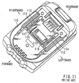
- a battery of this publication includes a lid 110 that is a part of a battery housing.
- a pair of right and left guide slits 112 are formed in the lid 110 and extend in a forward and rearward direction.
- the guide slits 112 are configured such that plate-like terminals of a power tool or a battery charger (not shown) can be inserted into the guide slits 112 from the front side as the power tool or the battery charger is connected to the battery.
- a positive electrode 113 and a negative electrode 114 are connected to an electric circuit board (not shown) and are positioned on the inner side of the guide slits 112 (i.e., the inner side of the lid 110).
- the positive and negative electrodes 113 and 114 can be connected to the terminals of the power tool or the battery charger.
- a signal guide slit 117 and a connector opening 116 are formed in the lid 110 at positions between the guide slits 112.
- a signal electrode 115 connected to the electric circuit board is positioned on the inner side of the signal guide slit 117.
- the signal electrode 115 can be connected to a signal terminal of the power tool or the battery charger.
- a connector 119 is connected to the electric circuit board and extends outward through the connector opening 116. The connector 119 is bent to be oriented forwardly for connection with a connector (not shown) of the battery charger.
- the positive electrode 113, the negative electrode 114, etc. are positioned between the guide slits 112 formed in the lid 110, and the connector 119 protrudes outwardly through the opening 16. Therefore, when the tool battery is wetted with water, it may be possible that the water may enter inside of the battery housing through the guide slits 112, the connector opening 116, etc.
- a battery includes a battery housing and a plurality of battery terminals.
- the battery housing has a terminal mounting portion made of resin.
- the battery terminals are connectible with external terminals and are mounted to the terminal mounting portion so as to extend through the terminal mounting portion, so that each of the battery terminals has a first end positioned outside of the battery housing and a second end positioned inside of the battery housing.
- At least one of the battery terminals is integrated with the terminal mounting portion, so that there is no substantial clearance between the at least one of the battery terminals and a part of the terminal mounting portion, through which the at least one of the battery terminals extends.
- a battery for a power tool is connectible with the power tool for serving as a power source for driving the power tool and is also connectible with a battery charger for recharging the battery.
- the battery includes a battery housing made of resin and a plurality of battery terminals extending from an outside of the battery housing into inside of the battery housing through the battery housing.
- the battery terminals are connectible with terminals of the power tool or terminals of the battery charger. At least one of the battery terminals is integrated with the battery housing by an insertion molding technique.
- the at least one of the battery terminals is integrated with the battery housing by an insertion molding technique, there is no substantial clearance between the at least one battery terminal and a portion of the battery housing, through which the at least one battery terminal extend. Therefore, water may not enter inside of the battery housing from the portion of the battery housing, through which the at least one battery terminal extends.
- the at least one battery terminal may include discharge or charge terminals and signal terminals.
- the battery further includes an electric circuit board mounted to an inner surface of the battery housing so as to be connectible with the battery terminals. With this arrangement, it is possible to eliminate electric wires for connecting between the battery terminals and the electric circuit board.
- the battery may further include a seal member provided between the electric circuit board and the battery housing and surrounding electronic components mounted to the electric circuit board. Therefore, it is possible to prevent the electric circuit board from being wetted with water.
- the battery may further include a wall extending from the inner surface of the battery housing and surrounding the electric circuit board.
- a filling material having a waterproof property may be filled into a space inside of the wall, so that at least a part of the electric circuit board is embedded within the filling material.
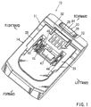
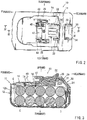
- a battery 10 has a battery housing 11 defining a storage space for storing a plurality of cylindrical battery cells C.
- ten battery cells C are stored within the battery housing 11.
- the battery housing 11 includes a housing body 12 and a lid 14.
- the housing body 12 has an upper opening 12h (see FIG. 3 ) that is closed by the lid 14.
- Each of the housing body 12 and the lid 14 has a substantially rectangular configuration in plan view.
- the peripheral portion of the lid 14 (see FIG. 5 ) is fixed to the housing body 12 at four positions by means of screws (not shown).
- the battery cells C are arranged such that their axes are parallel to the right and left direction (i.e., the widthwise direction) of the battery housing 11. More specifically, two sets of five battery cells C arranged in the forward and reward direction are vertically tiered.
- An electric circuit board 40 having an electric circuit (not shown) for performing a discharge control and a charge control of the battery cells C is positioned above the battery cells C.
- a hook member 30 having a slide lock function is disposed within the rear portion of the battery housing 11 and is biased upward by a coil spring 31, so that a pair of lock claws 32 disposed at an upper portion of the hook member 30 protrude upward from the battery housing 11.
- the lock claws 32 of the hook member 30 may engage a portion of a power tool or a battery charger (not shown) so as to prevent the power tool or the battery charge from sliding relative to the battery 10 and to hold the connecting condition between the battery 10 and the power tool or the battery charger.
- the lock claws 32 may be disengaged from the power tool or the battery charger when the operator pushes the hook member 30 downward against the biasing force of the coil spring 31, so that a slide lock between the battery 10 and the power tool or the battery charger can be released.
- a pair of slide rails 25 are formed on the upper surface of the lid 14.
- the slide rails 25 are positioned on opposite sides in the right and left direction and extend in the forward and rearward direction in the parallel to each other.
- a positive electrode 43 and a negative electrode 44 are positioned at a central portion (with respect to the right and left direction) between the slide rails 25 on the upper surface of the lid 14.
- the positive and negative electrodes 43 and 44 can be electrically connected to corresponding plate-like terminals (not shown) of the power tool or the battery charger when the power tool or the battery charge is mechanically connected to the battery 10 (i.e., the lid 14).
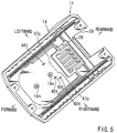
- the positive and negative electrodes 43 and 44 are disposed within the battery housing 11 such that their upper portions protrude upwardly from the upper surface of the lid 14 by a given distance so as to be exposed to the outside. Therefore, as the power tool or the battery charger moves to be slid on the battery 10 from the front side of the battery 10, the upper portions of the positive and negative electrodes 43 and 44 exposed to the outside may engage the corresponding plate-like terminals of the power tool of the battery charger so as to be electrically connected thereto. As shown in FIG. 5 , a portion 43t of the positive electrode 43 and a portion 44t of the negative electrode 44 that are positioned within the battery housing 11 (positioned on the inner side or the backside of the lid 14) are electrically connected to the electric circuit board 40.
- a first signal electrode 45 and a second signal electrode 46 are positioned on the left side of the positive electrode 43 and are arranged in line with each other in the forward and rearward direction. More specifically, the first and second signal electrodes 45 and 46 are disposed within the battery housing 11 such that their upper portions protrude upwardly from the upper surface of the lid 14 by a given distance so as to be exposed to the outside. Therefore, as the power tool or the battery charger moves to be slid on the battery 10 from the front side of the battery 10, the upper portions of the first and second signal electrodes 45 and 46 may receive corresponding signal terminals (not shown) of the power tool of the battery charger so as to be electrically connected thereto. As shown in FIG. 5 , a portion 45t of the first signal electrode 45 and a portion 46t of the second signal electrode 46 that are positioned within the battery housing 11 (positioned on the inner side of the backside of the lid 14) are electrically connected to the electric circuit board 40.
- a connector 47 is positioned between the negative electrode 44 and the first and second signal electrodes 45 and 46. More specifically, the connector 47 is disposed within the battery housing 11 such that its upper portion protrudes upwardly from the upper surface of the lid 14 by a given distance so as to be exposed to the outside. Therefore, as the battery charger moves to be slid on the battery 10 from the front side of the battery 10, the upper portion of the connector 47 may be electrically connected to a corresponding connector (not shown) of the battery charger. As shown in FIG. 5 , a conductor portion 47c of connector 47 that is positioned within the battery housing 11 (positioned on the inner side of the backside of the lid 14) is electrically connected to the electric circuit board 40.
- the connector 47, the positive electrode 43, the negative electrode 44, the first signal electrode 45 and the second signal electrode 46 (hereinafter called “battery terminals") are set within a mold that is used for molding the lid 14.
- the battery terminals With the battery terminals set within the mold, a resin is injected into the mold to form the lid 14, Therefore, the battery terminals are integrated with the lid 14 at the same time the lid 14 is molded.
- the battery terminals are integrated with the lid 14 by an insertion molding process.
- the positive and negative electrodes 43 and 44 may serves as discharge or charge terminals.
- the first and second signal electrodes 45 and 46 may serve as signal terminals.
- a claw opening 28 is formed in the rear portion of the lid 14 at a position on the rear side of the slide rails 25.
- the claw opening 28 includes a straight portion extending in the right and left direction and a pair of leg portions extending in the forward direction from opposite ends of the straight portion.
- the lock claws 32 of the hook member 30 extend from within the battery housing 11 upwardly of the lid 14 through the claw opening 28.
- a rectangular notch-like opening 29 is formed in the rear portion of the lid 14 at a position on the rear side of the claw opening 28.
- the hook member 30 has an operation portion 34 that protrudes upwardly from the lid 14 through the opening 29.
- the electric circuit board 40 has the electric circuit for performing a discharge control and a charge control of the battery cells C.
- the electric circuit may include a microcomputer and any other electronic elements necessary for the control.
- the electric circuit board 40 can be connect to the battery terminals including the connector 47, the positive electrode 43, the negative electrode 44, the first signal electrode 45 and the second signal electrode 46.
- the battery terminals are integrated with the lid 14. Therefore, the electric circuit board 40 is mounted to the inner surface (backside surface) of the lid 14 at a predetermined position that enables the electric circuit board 40 to be directly connected to the battery terminals. More specifically, as shown in FIG.
- two bottomed threaded holes 14n are formed in the inner surface (backside surface) of the lid 14 at positions spaced from each other in the forward and rearward direction. Screws 16 are inserted into corresponding insertion holes (not shown) formed in the electric circuit board 40 and are engaged with the threaded holes 14n, so that the electric circuit board 40 is fixed in position relative to the inner surface of the lid 14.
- a seal material 51 that may be an electrically insulating adhesive material is applied onto the upper surface of the electric circuit board 40 and is solidified thereon to cover a region where the microcomputer and any other electronic elements are mounted.
- the seal material 51 may be applied after the electric circuit board 40 has been electrically connected to the battery terminals.
- the battery terminals including the connector 47, the positive electrode 43, the negative electrode 44, the first signal electrode 45 and the second signal electrode 46 are integrated with the lid 14 by an insertion molding technique. Therefore, even in the case that the battery terminals extend through the lid 14 from its outer side to the inner side (backside), no substantial clearance may be provided between the battery terminals and portions of the lid 14 through which the battery terminals extend. More specifically, each of the battery terminals closely contacts with an inner wall of each of holes of the lid 14 formed to receive the battery terminals. As a result, water may not flow through the holes of the lid 14 toward the inner side (backside) of the lid 14.
- the battery terminals are integrated with the lid 14, no seal member is necessary provided between the battery terminals and portions of the lid 14 through which the battery terminals extend. Therefore, the waterproof property of the battery 10 can be improved without increase of the cost, which may be caused if seal members are provided.
- the electric circuit board 40 is mounted to the inner surface (backside surface) of the lid 14 and is fixed at a position that enables the battery terminals to be directly connected to the electric circuit board 40. Therefore, there is no need of providing electric wires for connecting between the electric circuit board 40 and the battery terminals.
- FIG. 8 shows only the mounting structure of the electric circuit board 40.
- a wall 14w extends vertically downward from the inner surface (backside surface) of the lid 14 and is configured to surround the electric circuit board 40 like a loop.
- the wall 14w has a vertical height to have a lower end positioned downwardly of the electric circuit board 40.
- the electric circuit board 40 is fixed in position relative to the inner side (backside) of the lid 14 by means of the screws 16 that are engaged with the threaded holes 14n in the same manner as the first example.
- a ring-shaped seal member 52 is provided between the upper surface of the electric circuit board 40 and the inner surface (backside surface) of the lid 14, so that the seal member 52 surrounds the microcomputer and any other electronic elements of the electric circuit board 40.
- the wall 14w surrounding the electric circuit board 40 may prevent water from reaching to the electric circuit board 40 along the inner surface of the lid 14 even in the event that water enters to the inner side (backside) of the lid 14.
- the seal member 52 surrounds the microcomputer and any other electronic elements of the electric circuit board 40, it is possible to further reliably prevent water from reaching to the electric elements of the electric circuit board 40.
- FIG. 9 shows only the mounting structure of the electric circuit board 40.
- the wall 14w surrounds the electric circuit board 40 like a loop and extends vertically downward from the inner surface (backside surface) of the lid 14.
- the screws 16 for fixing the electric circuit board 40 in position relative to the inner side surface of the lid 14 are eliminated.
- a filing material 54 is filled into a space that is surrounded by the wall 14w, so that the entire electric circuit board 40 is embedded within the filling material 54.
- the filling material 54 may be an adhesive material having an electrical insulation property and a water-proof property.
- the electric circuit board 40 can be further reliably prevented from being wetted with water, and it is possible to further firmly fix the electric circuit board 40 in position relative to the inner surface (backside surface) of the lid 14 without need of screws 16 that fix the electric circuit board 40 to the inner surface of the lid 14.
- a fourth example will now be described with reference to FIG. 10 .
- This example is a modification of the third example and is different from the third example in that the electric circuit board 40 are mounted to the inner surface of the lid 14 by using the screws 16 in addition to the filling material 54.
- the screws 16 are also embedded within the filling material 54.
- the battery terminals are directly electrically connected to the electric circuit board 40 in the above examples, it may be possible to electrically connect the battery terminals to the electric circuit board 40 by using lead wires.
- the battery terminals are integrated with the lid 14 by the insertion molding technique in the above examples, it may be possible to integrate only some of the battery terminals with the lid 14. For example, only the positive electrode 43 and the negative electrode 44 positioned on the outer side with respect to the widthwise direction may be integrated with the lid 14.
Claims (10)
- Batterie (10) comprenant :un boîtier de batterie (11) ayant une portion de montage de bornes (14) réalisée en résine ; etune pluralité de bornes de batterie (43, 44, 45, 46, 47) pouvant être connectées à des bornes externes et montées sur la portion de montage de bornes (14) de manière à s'étendre à travers la portion de montage de bornes (14), de manière que chacune des bornes de batterie (43, 44, 45, 46, 47) ait une première extrémité positionnée sur le côté extérieur du boîtier de batterie (11) et une deuxième extrémité positionnée sur le côté intérieur du boîtier de batterie (11) ;dans laquelle au moins une des bornes de batterie (43, 44, 45, 46, 47) est intégrée avec la portion de montage de bornes (14),caractérisée en ce que la batterie (10) comprend en outre une carte de circuit électrique (40) montée sur une surface intérieure de la portion de montage de bornes (14) dans une position prédéterminée qui permet à la carte de circuit électrique (40) d'être connectée directement aux bornés de batterie (43, 44, 45, 46, 47).
- Batterie selon la revendication 1, dans laquelle l'au moins une des bornes de batterie (43, 44, 45, 46, 47) est intégrée avec la portion de montage de bornes (14) en utilisant une technique de moulage par insertion.
- Batterie (10) selon la revendication 1 ou 2, dans laquelle
la batterie (10) peut être connectée à un outil électrique pour servir comme une source d'énergie pour entraîner l'outil électrique et peut être connectée avec un chargeur de batterie pour recharger la batterie (10) ;
le boîtier de batterie (11) comprenant la portion de montage de bornes (14) est réalisé en résine ; et
les bornes externes comprennent des bornes de l'outil électrique ou des bornes du chargeur de batterie. - Batterie (10) selon l'une quelconque des revendications précédentes, dans laquelle il n'existe aucun dégagement sensible entre l'au moins une des bornes de batterie (43, 44, 45, 46, 47) et une partie de la portion de montage de bornes (14), à travers laquelle l'au moins une des bornes de batterie (43, 44, 45, 46, 47) s'étend.
- Batterie (10) selon l'une quelconque des revendications précédentes, dans laquelle les bornes de batterie comprennent des bornes de décharge ou de charge (43, 44) et des bornes de signal (45, 46).
- Batterie (10) selon l'une quelconque des revendications précédentes, comprenant en outre un élément d'étanchéité (52) disposé entre la carte de circuit électrique (40) et la portion de montage de bornes (14) et entourant des composants électroniques montés sur la carte de circuit électrique (40).
- Batterie (10) selon l'une quelconque des revendications précédentes, comprenant en outre une paroi (14w) s'étendant à partir de la surface intérieure de la portion de montage de bornes (14) et entourant la carte de circuit électrique (40).
- Batterie (10) selon la revendication 7, comprenant en outre un matériau de remplissage (54) ayant une propriété d'imperméabilité et rempli dans un espace défini à l'intérieur de la paroi (14w), de manière qu'au moins une partie de la carte de circuit électrique (40) soit noyée dans le matériau de remplissage (54).
- Batterie (10) selon l'une quelconque des revendications précédentes, dans laquelle le boîtier de batterie (11) comprend un corps de boîtier (12) ayant un côté ouvert et un couvercle (14) monté sur le corps de boîtier (12) pour fermer le côté ouvert, et le couvercle (14) comprend la portion de montage de bornes.
- Procédé de montage d'au moins une borne de batterie sur une portion de montage de bornes (14) d'un boîtier de batterie (11), comprenant :l'intégration de l'au moins une borne de batterie (43, 44, 45, 46, 47) avec la portion de montage de bornes (14) en utilisant une technique de moulage par insertion, de manière que l'au moins une borne de batterie (43, 44, 45, 46, 47) s'étende à travers la portion de montage de bornes (14), l'au moins une borne de batterie (43, 44, 45, 46, 47) ayant une première extrémité positionnée à l'extérieur du boîtier de batterie (11) et une deuxième extrémité positionnée à l'intérieur du boîtier de batterie (11) ; etle montage d'une carte de circuit électrique (40) sur une surface intérieure de la portion de montage de bornes (14) dans une position prédéterminée qui permet à la carte de circuit électrique (40) d'être connectée directement à l'au moins une borne de batterie (43, 44, 45, 46, 47).
Applications Claiming Priority (1)
| Application Number | Priority Date | Filing Date | Title |
|---|---|---|---|
| JP2011028298A JP5524105B2 (ja) | 2011-02-14 | 2011-02-14 | 電動工具用バッテリ |
Publications (2)
| Publication Number | Publication Date |
|---|---|
| EP2487736A1 EP2487736A1 (fr) | 2012-08-15 |
| EP2487736B1 true EP2487736B1 (fr) | 2016-04-27 |
Family
ID=45571468
Family Applications (1)
| Application Number | Title | Priority Date | Filing Date |
|---|---|---|---|
| EP12155207.9A Active EP2487736B1 (fr) | 2011-02-14 | 2012-02-13 | Batteries pour outils électriques et procédés d'assemblage de bornes de batteries dans des boîtiers de batterie |
Country Status (5)
| Country | Link |
|---|---|
| US (1) | US20120208048A1 (fr) |
| EP (1) | EP2487736B1 (fr) |
| JP (1) | JP5524105B2 (fr) |
| CN (1) | CN102637838A (fr) |
| RU (1) | RU2012104998A (fr) |
Cited By (1)
| Publication number | Priority date | Publication date | Assignee | Title |
|---|---|---|---|---|
| US11777151B2 (en) | 2017-06-14 | 2023-10-03 | Milwaukee Electric Tool Corporation | Arrangements for inhibiting intrusion into battery pack electrical components |
Families Citing this family (16)
| Publication number | Priority date | Publication date | Assignee | Title |
|---|---|---|---|---|
| DE102009012176A1 (de) * | 2009-02-27 | 2010-09-02 | Andreas Stihl Ag & Co. Kg | Akkupack mit im Gehäusedeckel integrierter Überwachungselektronik |
| DE102011081819A1 (de) * | 2011-08-30 | 2013-02-28 | Robert Bosch Gmbh | Akkumulator |
| JP5847559B2 (ja) * | 2011-11-25 | 2016-01-27 | 三洋電機株式会社 | 電池パック |
| US10263228B2 (en) * | 2012-08-14 | 2019-04-16 | Koki Holdings Co., Ltd. | Electric device including sealing member between attachment part and battery pack |
| JP6284709B2 (ja) * | 2013-04-05 | 2018-02-28 | 株式会社マキタ | 電動工具用電池パック |
| JP6443936B2 (ja) * | 2013-08-30 | 2018-12-26 | Necエナジーデバイス株式会社 | 電池パック |
| DE102014205216A1 (de) * | 2013-09-16 | 2015-03-19 | Robert Bosch Gmbh | Akkuvorrichtung |
| DE102013218531A1 (de) * | 2013-09-16 | 2015-03-19 | Robert Bosch Gmbh | Akkuvorrichtung |
| US10076833B2 (en) * | 2013-10-10 | 2018-09-18 | Makita Corporation | Electric tools |
| US9634503B2 (en) * | 2014-02-26 | 2017-04-25 | Makita Corporation | Battery chargers |
| JP6112495B1 (ja) * | 2016-02-19 | 2017-04-12 | パナソニックIpマネジメント株式会社 | 電子機器用ハンドストラップ |
| EP3269514A1 (fr) * | 2016-07-11 | 2018-01-17 | HILTI Aktiengesellschaft | Appareil de pose |
| CN107799680A (zh) * | 2016-08-31 | 2018-03-13 | 苏州宝时得电动工具有限公司 | 防水电池包 |
| DE102016120329A1 (de) * | 2016-10-25 | 2018-04-26 | Festool Gmbh | Anschlussvorrichtung eines Elektrogeräts oder eines Energiespeichers |
| JP2020530648A (ja) * | 2017-09-22 | 2020-10-22 | ▲蘇▼州宝▲時▼得▲電▼▲動▼工具有限公司 | 電池パック及び電動工具ユニット |
| CN110459707A (zh) | 2018-05-07 | 2019-11-15 | 苏州宝时得电动工具有限公司 | 电池包及电动工具组件 |
Family Cites Families (17)
| Publication number | Priority date | Publication date | Assignee | Title |
|---|---|---|---|---|
| JPH05325941A (ja) * | 1992-05-28 | 1993-12-10 | Shin Kobe Electric Mach Co Ltd | 密閉形鉛蓄電池の製造法 |
| JP3543331B2 (ja) * | 1992-11-13 | 2004-07-14 | 松下電工株式会社 | 電池パック |
| JP3604728B2 (ja) * | 1994-05-25 | 2004-12-22 | 東芝電池株式会社 | 組電池 |
| EP0734083B1 (fr) * | 1995-02-23 | 1999-12-01 | Makita Corporation | Dispositif de fixation de piles compactes à des outils électriques |
| JPH11185719A (ja) * | 1997-12-25 | 1999-07-09 | Rohm Co Ltd | 電気部品の保護ケース、および充電池パック |
| JP3698296B2 (ja) * | 1999-08-19 | 2005-09-21 | 株式会社マキタ | 端子構造 |
| JP3792967B2 (ja) | 1999-11-15 | 2006-07-05 | 株式会社マキタ | バッテリーパック及び電動工具 |
| TWI221345B (en) * | 2001-03-30 | 2004-09-21 | Sanyo Gs Soft Energy Co Ltd | Battery pack |
| JP4593897B2 (ja) * | 2003-10-03 | 2010-12-08 | パナソニック株式会社 | 電池パック |
| JP4784067B2 (ja) * | 2004-10-29 | 2011-09-28 | トヨタ自動車株式会社 | 蓄電モジュール |
| JP2008140711A (ja) * | 2006-12-04 | 2008-06-19 | Sanyo Electric Co Ltd | パック電池 |
| JP5370709B2 (ja) * | 2007-10-29 | 2013-12-18 | 日立工機株式会社 | 電池パック及びこれを備えた電動工具 |
| JP2009104793A (ja) * | 2007-10-19 | 2009-05-14 | Toyota Motor Corp | 電池用端子構造 |
| DE102009012176A1 (de) * | 2009-02-27 | 2010-09-02 | Andreas Stihl Ag & Co. Kg | Akkupack mit im Gehäusedeckel integrierter Überwachungselektronik |
| US9263724B2 (en) * | 2009-10-12 | 2016-02-16 | Samsung Sdi Co., Ltd. | Battery pack |
| JP2011217571A (ja) * | 2010-04-01 | 2011-10-27 | Sanyo Electric Co Ltd | 電池パック用充電器 |
| JP4697352B2 (ja) | 2010-11-08 | 2011-06-08 | 富士ゼロックス株式会社 | 定着装置及び画像形成装置 |
-
2011
- 2011-02-14 JP JP2011028298A patent/JP5524105B2/ja active Active
-
2012
- 2012-02-08 CN CN2012100273550A patent/CN102637838A/zh active Pending
- 2012-02-13 EP EP12155207.9A patent/EP2487736B1/fr active Active
- 2012-02-13 RU RU2012104998/07A patent/RU2012104998A/ru not_active Application Discontinuation
- 2012-02-14 US US13/396,173 patent/US20120208048A1/en not_active Abandoned
Non-Patent Citations (1)
| Title |
|---|
| None * |
Cited By (3)
| Publication number | Priority date | Publication date | Assignee | Title |
|---|---|---|---|---|
| US11777151B2 (en) | 2017-06-14 | 2023-10-03 | Milwaukee Electric Tool Corporation | Arrangements for inhibiting intrusion into battery pack electrical components |
| US11916203B2 (en) | 2017-06-14 | 2024-02-27 | Milwaukee Electric Tool Corporation | Arrangements for inhibiting intrusion into battery pack electrical components |
| US11923514B2 (en) | 2017-06-14 | 2024-03-05 | Milwaukee Electric Tool Corporation | Arrangements for inhibiting intrusion into battery pack electrical components |
Also Published As
| Publication number | Publication date |
|---|---|
| CN102637838A (zh) | 2012-08-15 |
| RU2012104998A (ru) | 2013-08-20 |
| EP2487736A1 (fr) | 2012-08-15 |
| JP2012169105A (ja) | 2012-09-06 |
| JP5524105B2 (ja) | 2014-06-18 |
| US20120208048A1 (en) | 2012-08-16 |
Similar Documents
| Publication | Publication Date | Title |
|---|---|---|
| EP2487736B1 (fr) | Batteries pour outils électriques et procédés d'assemblage de bornes de batteries dans des boîtiers de batterie | |
| CA3107432C (fr) | Dispositif d'assemblage de batterie | |
| KR102340898B1 (ko) | 조립성이 향상된 버스바 프레임을 구비한 배터리 모듈 | |
| US8741461B2 (en) | Battery pack having waterproof structure | |
| EP2207222B1 (fr) | Bloc-batteries | |
| KR20190071454A (ko) | 버스바 어셈블리를 포함하는 배터리 모듈 | |
| CN110783732B (zh) | 安装有连接器的电路体以及汇流条模块 | |
| JP4530711B2 (ja) | パック電池 | |
| US10158204B2 (en) | Fixing structure of conductor unit | |
| KR20170050511A (ko) | 배터리 모듈 및 이를 포함하는 배터리 팩 | |
| JP2018088334A (ja) | 配線モジュール | |
| JP5915460B2 (ja) | 温度センサの取付構造及び配線モジュールの製造方法 | |
| US20180090734A1 (en) | Energy storage apparatus | |
| KR100601502B1 (ko) | 팩 전지 | |
| JP2015056910A (ja) | 配線モジュール | |
| JP7014504B2 (ja) | 蓄電装置及び蓄電装置の製造方法 | |
| JP2004362874A (ja) | 電池パック | |
| US20180366713A1 (en) | Insulating protector and electricity storage module | |
| KR20180091442A (ko) | 배터리 모듈 및 배터리 모듈용 전압 센싱 조립체 | |
| KR20150049886A (ko) | 전지셀의 보호회로모듈 용접용 지그 | |
| KR102614276B1 (ko) | 퓨즈 박스 일체형 커넥터 블록 | |
| CN112771730B (zh) | 公连接器和具有该公连接器的收容装置 | |
| CN117795785A (zh) | 防水连接器和包括防水连接器的电池模块 | |
| JP2017126493A (ja) | サービスプラグを備えた車載用バッテリユニット | |
| CN114361674A (zh) | 电池包 |
Legal Events
| Date | Code | Title | Description |
|---|---|---|---|
| PUAI | Public reference made under article 153(3) epc to a published international application that has entered the european phase |
Free format text: ORIGINAL CODE: 0009012 |
|
| AK | Designated contracting states |
Kind code of ref document: A1 Designated state(s): AL AT BE BG CH CY CZ DE DK EE ES FI FR GB GR HR HU IE IS IT LI LT LU LV MC MK MT NL NO PL PT RO RS SE SI SK SM TR |
|
| AX | Request for extension of the european patent |
Extension state: BA ME |
|
| 17P | Request for examination filed |
Effective date: 20130206 |
|
| RIC1 | Information provided on ipc code assigned before grant |
Ipc: H01M 2/10 20060101AFI20150422BHEP Ipc: H01M 10/46 20060101ALN20150422BHEP Ipc: H01M 2/30 20060101ALI20150422BHEP |
|
| 17Q | First examination report despatched |
Effective date: 20150504 |
|
| GRAP | Despatch of communication of intention to grant a patent |
Free format text: ORIGINAL CODE: EPIDOSNIGR1 |
|
| RIC1 | Information provided on ipc code assigned before grant |
Ipc: H01M 2/10 20060101AFI20151103BHEP Ipc: H01M 2/30 20060101ALI20151103BHEP Ipc: H01M 10/46 20060101ALN20151103BHEP |
|
| RIC1 | Information provided on ipc code assigned before grant |
Ipc: H01M 2/10 20060101AFI20151110BHEP Ipc: H01M 2/30 20060101ALI20151110BHEP Ipc: H01M 10/46 20060101ALN20151110BHEP |
|
| INTG | Intention to grant announced |
Effective date: 20151209 |
|
| GRAS | Grant fee paid |
Free format text: ORIGINAL CODE: EPIDOSNIGR3 |
|
| GRAA | (expected) grant |
Free format text: ORIGINAL CODE: 0009210 |
|
| INTG | Intention to grant announced |
Effective date: 20160303 |
|
| RIC1 | Information provided on ipc code assigned before grant |
Ipc: H01M 2/30 20060101ALI20160229BHEP Ipc: H01M 10/46 20060101ALN20160229BHEP Ipc: H01M 2/10 20060101AFI20160229BHEP |
|
| AK | Designated contracting states |
Kind code of ref document: B1 Designated state(s): AL AT BE BG CH CY CZ DE DK EE ES FI FR GB GR HR HU IE IS IT LI LT LU LV MC MK MT NL NO PL PT RO RS SE SI SK SM TR |
|
| REG | Reference to a national code |
Ref country code: GB Ref legal event code: FG4D |
|
| REG | Reference to a national code |
Ref country code: CH Ref legal event code: EP |
|
| REG | Reference to a national code |
Ref country code: AT Ref legal event code: REF Ref document number: 795665 Country of ref document: AT Kind code of ref document: T Effective date: 20160515 |
|
| REG | Reference to a national code |
Ref country code: IE Ref legal event code: FG4D |
|
| REG | Reference to a national code |
Ref country code: DE Ref legal event code: R096 Ref document number: 602012017519 Country of ref document: DE |
|
| REG | Reference to a national code |
Ref country code: LT Ref legal event code: MG4D |
|
| REG | Reference to a national code |
Ref country code: NL Ref legal event code: MP Effective date: 20160427 |
|
| REG | Reference to a national code |
Ref country code: AT Ref legal event code: MK05 Ref document number: 795665 Country of ref document: AT Kind code of ref document: T Effective date: 20160427 |
|
| PG25 | Lapsed in a contracting state [announced via postgrant information from national office to epo] |
Ref country code: NL Free format text: LAPSE BECAUSE OF FAILURE TO SUBMIT A TRANSLATION OF THE DESCRIPTION OR TO PAY THE FEE WITHIN THE PRESCRIBED TIME-LIMIT Effective date: 20160427 |
|
| PG25 | Lapsed in a contracting state [announced via postgrant information from national office to epo] |
Ref country code: PL Free format text: LAPSE BECAUSE OF FAILURE TO SUBMIT A TRANSLATION OF THE DESCRIPTION OR TO PAY THE FEE WITHIN THE PRESCRIBED TIME-LIMIT Effective date: 20160427 Ref country code: FI Free format text: LAPSE BECAUSE OF FAILURE TO SUBMIT A TRANSLATION OF THE DESCRIPTION OR TO PAY THE FEE WITHIN THE PRESCRIBED TIME-LIMIT Effective date: 20160427 Ref country code: NO Free format text: LAPSE BECAUSE OF FAILURE TO SUBMIT A TRANSLATION OF THE DESCRIPTION OR TO PAY THE FEE WITHIN THE PRESCRIBED TIME-LIMIT Effective date: 20160727 Ref country code: LT Free format text: LAPSE BECAUSE OF FAILURE TO SUBMIT A TRANSLATION OF THE DESCRIPTION OR TO PAY THE FEE WITHIN THE PRESCRIBED TIME-LIMIT Effective date: 20160427 |
|
| PG25 | Lapsed in a contracting state [announced via postgrant information from national office to epo] |
Ref country code: RS Free format text: LAPSE BECAUSE OF FAILURE TO SUBMIT A TRANSLATION OF THE DESCRIPTION OR TO PAY THE FEE WITHIN THE PRESCRIBED TIME-LIMIT Effective date: 20160427 Ref country code: GR Free format text: LAPSE BECAUSE OF FAILURE TO SUBMIT A TRANSLATION OF THE DESCRIPTION OR TO PAY THE FEE WITHIN THE PRESCRIBED TIME-LIMIT Effective date: 20160728 Ref country code: LV Free format text: LAPSE BECAUSE OF FAILURE TO SUBMIT A TRANSLATION OF THE DESCRIPTION OR TO PAY THE FEE WITHIN THE PRESCRIBED TIME-LIMIT Effective date: 20160427 Ref country code: AT Free format text: LAPSE BECAUSE OF FAILURE TO SUBMIT A TRANSLATION OF THE DESCRIPTION OR TO PAY THE FEE WITHIN THE PRESCRIBED TIME-LIMIT Effective date: 20160427 Ref country code: PT Free format text: LAPSE BECAUSE OF FAILURE TO SUBMIT A TRANSLATION OF THE DESCRIPTION OR TO PAY THE FEE WITHIN THE PRESCRIBED TIME-LIMIT Effective date: 20160829 Ref country code: HR Free format text: LAPSE BECAUSE OF FAILURE TO SUBMIT A TRANSLATION OF THE DESCRIPTION OR TO PAY THE FEE WITHIN THE PRESCRIBED TIME-LIMIT Effective date: 20160427 Ref country code: SE Free format text: LAPSE BECAUSE OF FAILURE TO SUBMIT A TRANSLATION OF THE DESCRIPTION OR TO PAY THE FEE WITHIN THE PRESCRIBED TIME-LIMIT Effective date: 20160427 Ref country code: ES Free format text: LAPSE BECAUSE OF FAILURE TO SUBMIT A TRANSLATION OF THE DESCRIPTION OR TO PAY THE FEE WITHIN THE PRESCRIBED TIME-LIMIT Effective date: 20160427 |
|
| PG25 | Lapsed in a contracting state [announced via postgrant information from national office to epo] |
Ref country code: BE Free format text: LAPSE BECAUSE OF FAILURE TO SUBMIT A TRANSLATION OF THE DESCRIPTION OR TO PAY THE FEE WITHIN THE PRESCRIBED TIME-LIMIT Effective date: 20160427 Ref country code: IT Free format text: LAPSE BECAUSE OF FAILURE TO SUBMIT A TRANSLATION OF THE DESCRIPTION OR TO PAY THE FEE WITHIN THE PRESCRIBED TIME-LIMIT Effective date: 20160427 |
|
| REG | Reference to a national code |
Ref country code: DE Ref legal event code: R097 Ref document number: 602012017519 Country of ref document: DE |
|
| PG25 | Lapsed in a contracting state [announced via postgrant information from national office to epo] |
Ref country code: RO Free format text: LAPSE BECAUSE OF FAILURE TO SUBMIT A TRANSLATION OF THE DESCRIPTION OR TO PAY THE FEE WITHIN THE PRESCRIBED TIME-LIMIT Effective date: 20160427 Ref country code: EE Free format text: LAPSE BECAUSE OF FAILURE TO SUBMIT A TRANSLATION OF THE DESCRIPTION OR TO PAY THE FEE WITHIN THE PRESCRIBED TIME-LIMIT Effective date: 20160427 Ref country code: SK Free format text: LAPSE BECAUSE OF FAILURE TO SUBMIT A TRANSLATION OF THE DESCRIPTION OR TO PAY THE FEE WITHIN THE PRESCRIBED TIME-LIMIT Effective date: 20160427 Ref country code: CZ Free format text: LAPSE BECAUSE OF FAILURE TO SUBMIT A TRANSLATION OF THE DESCRIPTION OR TO PAY THE FEE WITHIN THE PRESCRIBED TIME-LIMIT Effective date: 20160427 Ref country code: DK Free format text: LAPSE BECAUSE OF FAILURE TO SUBMIT A TRANSLATION OF THE DESCRIPTION OR TO PAY THE FEE WITHIN THE PRESCRIBED TIME-LIMIT Effective date: 20160427 |
|
| PG25 | Lapsed in a contracting state [announced via postgrant information from national office to epo] |
Ref country code: SM Free format text: LAPSE BECAUSE OF FAILURE TO SUBMIT A TRANSLATION OF THE DESCRIPTION OR TO PAY THE FEE WITHIN THE PRESCRIBED TIME-LIMIT Effective date: 20160427 |
|
| PLBE | No opposition filed within time limit |
Free format text: ORIGINAL CODE: 0009261 |
|
| STAA | Information on the status of an ep patent application or granted ep patent |
Free format text: STATUS: NO OPPOSITION FILED WITHIN TIME LIMIT |
|
| 26N | No opposition filed |
Effective date: 20170130 |
|
| PG25 | Lapsed in a contracting state [announced via postgrant information from national office to epo] |
Ref country code: SI Free format text: LAPSE BECAUSE OF FAILURE TO SUBMIT A TRANSLATION OF THE DESCRIPTION OR TO PAY THE FEE WITHIN THE PRESCRIBED TIME-LIMIT Effective date: 20160427 |
|
| PG25 | Lapsed in a contracting state [announced via postgrant information from national office to epo] |
Ref country code: MC Free format text: LAPSE BECAUSE OF FAILURE TO SUBMIT A TRANSLATION OF THE DESCRIPTION OR TO PAY THE FEE WITHIN THE PRESCRIBED TIME-LIMIT Effective date: 20160427 |
|
| REG | Reference to a national code |
Ref country code: CH Ref legal event code: PL |
|
| GBPC | Gb: european patent ceased through non-payment of renewal fee |
Effective date: 20170213 |
|
| PG25 | Lapsed in a contracting state [announced via postgrant information from national office to epo] |
Ref country code: CH Free format text: LAPSE BECAUSE OF NON-PAYMENT OF DUE FEES Effective date: 20170228 Ref country code: LI Free format text: LAPSE BECAUSE OF NON-PAYMENT OF DUE FEES Effective date: 20170228 |
|
| REG | Reference to a national code |
Ref country code: IE Ref legal event code: MM4A |
|
| REG | Reference to a national code |
Ref country code: FR Ref legal event code: ST Effective date: 20171031 |
|
| PG25 | Lapsed in a contracting state [announced via postgrant information from national office to epo] |
Ref country code: LU Free format text: LAPSE BECAUSE OF NON-PAYMENT OF DUE FEES Effective date: 20170213 |
|
| PG25 | Lapsed in a contracting state [announced via postgrant information from national office to epo] |
Ref country code: FR Free format text: LAPSE BECAUSE OF NON-PAYMENT OF DUE FEES Effective date: 20170228 |
|
| PG25 | Lapsed in a contracting state [announced via postgrant information from national office to epo] |
Ref country code: GB Free format text: LAPSE BECAUSE OF NON-PAYMENT OF DUE FEES Effective date: 20170213 Ref country code: IE Free format text: LAPSE BECAUSE OF NON-PAYMENT OF DUE FEES Effective date: 20170213 |
|
| PG25 | Lapsed in a contracting state [announced via postgrant information from national office to epo] |
Ref country code: MT Free format text: LAPSE BECAUSE OF NON-PAYMENT OF DUE FEES Effective date: 20170213 |
|
| PG25 | Lapsed in a contracting state [announced via postgrant information from national office to epo] |
Ref country code: AL Free format text: LAPSE BECAUSE OF FAILURE TO SUBMIT A TRANSLATION OF THE DESCRIPTION OR TO PAY THE FEE WITHIN THE PRESCRIBED TIME-LIMIT Effective date: 20160427 |
|
| PG25 | Lapsed in a contracting state [announced via postgrant information from national office to epo] |
Ref country code: HU Free format text: LAPSE BECAUSE OF FAILURE TO SUBMIT A TRANSLATION OF THE DESCRIPTION OR TO PAY THE FEE WITHIN THE PRESCRIBED TIME-LIMIT; INVALID AB INITIO Effective date: 20120213 |
|
| PG25 | Lapsed in a contracting state [announced via postgrant information from national office to epo] |
Ref country code: BG Free format text: LAPSE BECAUSE OF FAILURE TO SUBMIT A TRANSLATION OF THE DESCRIPTION OR TO PAY THE FEE WITHIN THE PRESCRIBED TIME-LIMIT Effective date: 20160427 |
|
| PG25 | Lapsed in a contracting state [announced via postgrant information from national office to epo] |
Ref country code: CY Free format text: LAPSE BECAUSE OF NON-PAYMENT OF DUE FEES Effective date: 20160427 |
|
| PG25 | Lapsed in a contracting state [announced via postgrant information from national office to epo] |
Ref country code: MK Free format text: LAPSE BECAUSE OF FAILURE TO SUBMIT A TRANSLATION OF THE DESCRIPTION OR TO PAY THE FEE WITHIN THE PRESCRIBED TIME-LIMIT Effective date: 20160427 |
|
| PG25 | Lapsed in a contracting state [announced via postgrant information from national office to epo] |
Ref country code: TR Free format text: LAPSE BECAUSE OF FAILURE TO SUBMIT A TRANSLATION OF THE DESCRIPTION OR TO PAY THE FEE WITHIN THE PRESCRIBED TIME-LIMIT Effective date: 20160427 |
|
| PG25 | Lapsed in a contracting state [announced via postgrant information from national office to epo] |
Ref country code: IS Free format text: LAPSE BECAUSE OF FAILURE TO SUBMIT A TRANSLATION OF THE DESCRIPTION OR TO PAY THE FEE WITHIN THE PRESCRIBED TIME-LIMIT Effective date: 20160827 |
|
| REG | Reference to a national code |
Ref country code: DE Ref legal event code: R079 Ref document number: 602012017519 Country of ref document: DE Free format text: PREVIOUS MAIN CLASS: H01M0002100000 Ipc: H01M0050200000 |
|
| PGFP | Annual fee paid to national office [announced via postgrant information from national office to epo] |
Ref country code: DE Payment date: 20231228 Year of fee payment: 13 |