EP2483496B1 - Belag aus mechanisch miteinander verbindbaren elementen - Google Patents
Belag aus mechanisch miteinander verbindbaren elementen Download PDFInfo
- Publication number
- EP2483496B1 EP2483496B1 EP10779208.7A EP10779208A EP2483496B1 EP 2483496 B1 EP2483496 B1 EP 2483496B1 EP 10779208 A EP10779208 A EP 10779208A EP 2483496 B1 EP2483496 B1 EP 2483496B1
- Authority
- EP
- European Patent Office
- Prior art keywords
- elements
- covering according
- tongue
- spring element
- locking
- Prior art date
- Legal status (The legal status is an assumption and is not a legal conclusion. Google has not performed a legal analysis and makes no representation as to the accuracy of the status listed.)
- Active
Links
- 239000013013 elastic material Substances 0.000 claims description 20
- 239000000853 adhesive Substances 0.000 claims description 6
- 230000001070 adhesive effect Effects 0.000 claims description 6
- 238000006073 displacement reaction Methods 0.000 claims description 4
- 239000004823 Reactive adhesive Substances 0.000 claims description 3
- 230000000295 complement effect Effects 0.000 claims 1
- 238000009434 installation Methods 0.000 claims 1
- 239000011162 core material Substances 0.000 description 34
- 239000000463 material Substances 0.000 description 12
- 238000004519 manufacturing process Methods 0.000 description 4
- 239000004033 plastic Substances 0.000 description 4
- 229920003023 plastic Polymers 0.000 description 4
- 230000008878 coupling Effects 0.000 description 3
- 238000010168 coupling process Methods 0.000 description 3
- 238000005859 coupling reaction Methods 0.000 description 3
- 230000007704 transition Effects 0.000 description 3
- 239000002023 wood Substances 0.000 description 3
- 239000011324 bead Substances 0.000 description 2
- 238000010276 construction Methods 0.000 description 2
- 238000011161 development Methods 0.000 description 2
- 230000018109 developmental process Effects 0.000 description 2
- 238000005516 engineering process Methods 0.000 description 2
- 239000000565 sealant Substances 0.000 description 2
- 239000004820 Pressure-sensitive adhesive Substances 0.000 description 1
- 150000001252 acrylic acid derivatives Chemical class 0.000 description 1
- 238000005452 bending Methods 0.000 description 1
- 230000015572 biosynthetic process Effects 0.000 description 1
- 238000006243 chemical reaction Methods 0.000 description 1
- 239000011093 chipboard Substances 0.000 description 1
- 239000007799 cork Substances 0.000 description 1
- 230000001419 dependent effect Effects 0.000 description 1
- 230000000694 effects Effects 0.000 description 1
- 229920001971 elastomer Polymers 0.000 description 1
- 239000000806 elastomer Substances 0.000 description 1
- 239000000835 fiber Substances 0.000 description 1
- 238000009408 flooring Methods 0.000 description 1
- 239000012634 fragment Substances 0.000 description 1
- 239000011440 grout Substances 0.000 description 1
- 229910052602 gypsum Inorganic materials 0.000 description 1
- 239000010440 gypsum Substances 0.000 description 1
- 239000012943 hotmelt Substances 0.000 description 1
- 239000007788 liquid Substances 0.000 description 1
- 239000002991 molded plastic Substances 0.000 description 1
- 238000000465 moulding Methods 0.000 description 1
- 239000000123 paper Substances 0.000 description 1
- 229920001296 polysiloxane Polymers 0.000 description 1
- 238000007789 sealing Methods 0.000 description 1
- 239000011343 solid material Substances 0.000 description 1
Images

Classifications
-
- F—MECHANICAL ENGINEERING; LIGHTING; HEATING; WEAPONS; BLASTING
- F16—ENGINEERING ELEMENTS AND UNITS; GENERAL MEASURES FOR PRODUCING AND MAINTAINING EFFECTIVE FUNCTIONING OF MACHINES OR INSTALLATIONS; THERMAL INSULATION IN GENERAL
- F16B—DEVICES FOR FASTENING OR SECURING CONSTRUCTIONAL ELEMENTS OR MACHINE PARTS TOGETHER, e.g. NAILS, BOLTS, CIRCLIPS, CLAMPS, CLIPS OR WEDGES; JOINTS OR JOINTING
- F16B5/00—Joining sheets or plates, e.g. panels, to one another or to strips or bars parallel to them
- F16B5/0004—Joining sheets, plates or panels in abutting relationship
- F16B5/0056—Joining sheets, plates or panels in abutting relationship by moving the sheets, plates or panels or the interlocking key perpendicular to the main plane
- F16B5/0076—Joining sheets, plates or panels in abutting relationship by moving the sheets, plates or panels or the interlocking key perpendicular to the main plane and using expanding clamps
-
- E—FIXED CONSTRUCTIONS
- E04—BUILDING
- E04F—FINISHING WORK ON BUILDINGS, e.g. STAIRS, FLOORS
- E04F13/00—Coverings or linings, e.g. for walls or ceilings
- E04F13/07—Coverings or linings, e.g. for walls or ceilings composed of covering or lining elements; Sub-structures therefor; Fastening means therefor
- E04F13/08—Coverings or linings, e.g. for walls or ceilings composed of covering or lining elements; Sub-structures therefor; Fastening means therefor composed of a plurality of similar covering or lining elements
-
- E—FIXED CONSTRUCTIONS
- E04—BUILDING
- E04F—FINISHING WORK ON BUILDINGS, e.g. STAIRS, FLOORS
- E04F15/00—Flooring
- E04F15/02—Flooring or floor layers composed of a number of similar elements
-
- E—FIXED CONSTRUCTIONS
- E04—BUILDING
- E04F—FINISHING WORK ON BUILDINGS, e.g. STAIRS, FLOORS
- E04F15/00—Flooring
- E04F15/02—Flooring or floor layers composed of a number of similar elements
- E04F15/024—Sectional false floors, e.g. computer floors
- E04F15/02405—Floor panels
-
- E—FIXED CONSTRUCTIONS
- E04—BUILDING
- E04F—FINISHING WORK ON BUILDINGS, e.g. STAIRS, FLOORS
- E04F2201/00—Joining sheets or plates or panels
- E04F2201/01—Joining sheets, plates or panels with edges in abutting relationship
- E04F2201/0138—Joining sheets, plates or panels with edges in abutting relationship by moving the sheets, plates or panels perpendicular to the main plane
- E04F2201/0146—Joining sheets, plates or panels with edges in abutting relationship by moving the sheets, plates or panels perpendicular to the main plane with snap action of the edge connectors
-
- E—FIXED CONSTRUCTIONS
- E04—BUILDING
- E04F—FINISHING WORK ON BUILDINGS, e.g. STAIRS, FLOORS
- E04F2201/00—Joining sheets or plates or panels
- E04F2201/01—Joining sheets, plates or panels with edges in abutting relationship
- E04F2201/0169—Joining sheets, plates or panels with edges in abutting relationship by rotating the sheets, plates or panels around an axis which is perpendicular to the abutting edges and parallel to the main plane, possibly combined with a sliding movement
- E04F2201/0176—Joining sheets, plates or panels with edges in abutting relationship by rotating the sheets, plates or panels around an axis which is perpendicular to the abutting edges and parallel to the main plane, possibly combined with a sliding movement with snap action of the edge connectors
-
- E—FIXED CONSTRUCTIONS
- E04—BUILDING
- E04F—FINISHING WORK ON BUILDINGS, e.g. STAIRS, FLOORS
- E04F2201/00—Joining sheets or plates or panels
- E04F2201/04—Other details of tongues or grooves
- E04F2201/041—Tongues or grooves with slits or cuts for expansion or flexibility
-
- E—FIXED CONSTRUCTIONS
- E04—BUILDING
- E04F—FINISHING WORK ON BUILDINGS, e.g. STAIRS, FLOORS
- E04F2201/00—Joining sheets or plates or panels
- E04F2201/04—Other details of tongues or grooves
- E04F2201/044—Other details of tongues or grooves with tongues or grooves comprising elements which are not manufactured in one piece with the sheets, plates or panels but which are permanently fixedly connected to the sheets, plates or panels, e.g. at the factory
- E04F2201/049—Other details of tongues or grooves with tongues or grooves comprising elements which are not manufactured in one piece with the sheets, plates or panels but which are permanently fixedly connected to the sheets, plates or panels, e.g. at the factory wherein the elements are made of organic plastics with or without reinforcements or filling materials
Definitions
- the invention relates to a covering of mechanically interconnectable elements.
- Wall, ceiling and floor coverings such as Prefabricated parquet, wooden floors or laminate floors consist of several rows of rectangular panels in their configuration.
- the panels have on a longitudinal side and on a head side continuous grooves and on the respective opposite longitudinal side or head side continuous springs, which are adapted to the grooves form-fitting manner. By connecting tongue and groove the panels are laid, the panels of two adjacent rows are offset from one another.
- a covering with mechanically connectable elements in the form of floor panels is known, which have on their opposite sides a corresponding profiling and are lockable on this.
- the locking is effected by an elastic spring element, which is articulated on one of the elements by a positive connection and is pivotable behind a locking edge extending in the horizontal direction of the adjacent panel.
- the spring element is connected in the initial position via a pressure-sensitive adhesive as a predetermined breaking point with the element.
- the predetermined breaking point fails during pivoting of the spring element.
- the production of a positive connection for defining the pivot point of the spring element is relatively complicated.
- the prior art is also the WO2004 / 003314 A1 to call, which relates to a floor system with panels, which are locked together at their side edges.
- the lock provides a one-piece arranged on the one panel, vertical spring element, which has on its side facing away from the other panel has a Elastizticiansnut, with an elastic means such.
- B is filled with a PVC adhesive.
- the spring element can be deflected laterally during locking and remains firmly connected to the panel even after locking. If the spring element were to break off, it would have to be held in position by the elastic means.
- due to the vertical orientation of the spring element would inevitably adjust a height offset between the panels.
- the invention is based on the object to show a covering of mechanically interconnectable elements, which can be locked securely with little effort and which is easy to produce.
- the covering according to the invention comprises elements that can be mechanically connected to one another, wherein at least one of the elements is a panel.
- the invention includes the possibility that one of the elements as a panel and the other element is designed as a frame member for a frame construction, for example, for raised floors.
- the following description of the invention relates to an embodiment in which the elements to be joined are panels.
- the elements have at their opposite sides of a mutually corresponding profiling, by means of which adjacent elements by a substantially vertical or pivoting joining movement in the horizontal direction and vertical direction are locked together.
- a mutually corresponding profiling by means of which adjacent elements by a substantially vertical or pivoting joining movement in the horizontal direction and vertical direction are locked together.
- the opposite, provided with a corresponding profiling in the sense of the present invention pages are in particular head sides of the elements.
- the profiling can in principle be provided on all sides, that is to say the top sides and the long sides, of the essentially rectangular elements.
- the locking is effected by at least one spring element which is connected to one of the elements for a regionally via an elastic material with a core of the element and on the other hand before the joining movement integral part of the element.
- the elastic material is introduced into a space between a core of the element facing back of the spring element and the core arranged free space.
- the spring element articulated in this way is pivotable in the joining movement behind a locking edge of the adjacent element extending essentially in the horizontal direction.
- the two elements Due to the fact that the locking edge extends substantially in the horizontal direction, the two elements against vertical displacement, i. perpendicular to the laying level, secured. Additional locking strips can be provided on the elements, in addition to the locking in the vertical direction, to effect the locks of the laying plane.
- the one-piece connection between the spring element and the element is configured as a predetermined breaking point, which is intended to fail during pivoting of the spring element, in particular to break.
- a predetermined breaking point which is intended to fail during pivoting of the spring element, in particular to break.
- pivoting or lowering of the spring element is thus preferably effected by the predetermined breaking point a targeted break between the spring element and the core of the element.
- the failure or breakage of the predetermined breaking point between spring element and core preferably takes place when first connecting two adjacent elements.
- the predetermined breaking point is configured so that when a certain load is exceeded a failure of the structure takes place precisely at this point to achieve the desired function, namely the displacement of the spring element.
- the failure is in particular a brittle fracture.
- failure can also occur in overstretching of the core material, i. H. exist in a permanent plastic deformation.
- the fracture mechanics depends on the material properties of the spring element, wherein the plastic deformation behavior depends, among other things, on the state of stress, the temperature, the type of load and the loading speed.
- breaking / breaking is used for the failure of the predetermined breaking point, regardless of whether it is a plastic deformation, a partial fracture or a complete brittle fracture.
- the spring element slides with its underside on one of the locking edge opposite support surface of the adjacent element.
- the spring element is due to a material-specific elasticity of the element, which allows a certain pivoting of the spring element relative to its starting position, without the material is plastically deformed, so yields or breaks, nor integral part of the element.
- the spring element Upon further lowering of the element, the spring element is further pivoted relative to its starting position.
- the spring element breaks off in the region of the predetermined breaking point quasi from the core, but at the same time remains connected to the core of the element via the elastic material.
- the failure of the predetermined breaking point ie in particular the break occurs as soon as the spring element engages in the horizontal position between a support surface and a bottom of the locking edge or shortly before, ie relatively late during the joining. If a break occurs before reaching the locking position, the breaking edge on the side of the core acts as an abutment, presses on the spring element-side breaking edge and thus causes the spring element to reach the locking position. In this case, the elastic material holds the spring element in position so that the broken edges are substantially opposite.
- a predetermined breaking notch can be provided for the targeted introduction of notch stresses and thus for the targeted positioning of the break point.
- the course of the breaklines can be at least partially influenced.
- the time of the break ie how far the spring element can be elastically pivoted out of its starting position before it breaks, can be determined.
- released material can be absorbed by the predetermined breaking notch.
- a cutout can also be arranged. This cutout can serve the recording of the break between the spring element and core possibly resulting material. Both the predetermined breaking notch and the free cut above the predetermined breaking point can be cut simultaneously with the contour of the spring element from the core, without increasing the production cost appreciably.
- the support surface, with which the spring element corresponds, is oriented substantially horizontally and lies opposite the locking edge.
- an underside of the locking edge to the support surface is parallel.
- the underside of the spring element which slides on the support surface when joining adjacent elements is preferably convex.
- an upper surface of the spring element is inclined prior to the joining movement, i. from the predetermined breaking point to the front and bottom of the element sloping down, formed. In the manufacture of the elements, the inclined upper side is cut free from the core after the elastic material has been introduced into the rear free space of the spring element.
- the spring element After joining, the spring element is in the locking position with its upper side against an underside of the locking edge in a substantially horizontal orientation.
- the elastic material is an adhesive, an elastomer, a reactive adhesive, a hot-melt or a permanently elastic sealing or grout.
- Reactive adhesive refers to adhesives that cure and set by chemical reactions. These sealants or sealants also include acrylates and silicones.
- the selection of the elastic material is of course dependent on the materials used for the elements in order to obtain a good adhesion between the elastic material and the element.
- the spring element configured according to the invention firstly does not have to overcome any spring force for locking in the sense that the spring element is pushed back by the adjacent side of the element. Instead, it is displaced exclusively in the direction of the adjacent element. The Spring element does not snap under the influence of a spring force behind the locking edge, but is forcibly pushed behind the locking edge.
- the spring element After failure, in particular the breakage of the predetermined breaking point, the spring element is connected only via the elastic material to the core.
- the elastic connection between spring element and core is configured so that it remains after the joining. If necessary, this connection makes it possible, despite breakage, to relocate the elements.
- the spring element can not automatically move back on the restoring forces of the elastic material, since it is held between the support surface and the underside of the locking edge.
- the spring element is in a state of self-locking and can not return to its original position without a foreign force, so that the elements are securely in the locked position, i. in the laying plane, are held.
- a friction-increasing profiling may preferably be provided on an underside of the locking edge and / or an upper side of the spring element.
- the spring elements can be arranged adjacent to each other or spaced apart.
- more than one spring element per side is arranged.
- spring elements of different elasticities can therefore also be arranged at a distance from each other.
- Manufacturing technology it is easiest if initially a single correspondingly long spring element is divided into individual sections. For this purpose, a plurality of slots can be formed in the originally single spring element, so that the individualized spring elements can be actuated in sequence when folding down.
- a connecting means may serve an elastic member, such. an elastic adhesive, as it also comes in the rear space of the spring element used.
- the elastic connection makes it possible to make the spring elements smaller, without the risk that solves a single spring element of the element in case of damage.
- the freedom of design is generally greater when the spring elements are additionally bonded together adhesive technology.
- the element having the locking edge has a locking strip under the element carrying the spring element.
- This locking bar is suitable and provided, the adjacent elements against tensile loads in one Secure laying level.
- the additional locking bar only horizontal tensile forces are absorbed, so tensile loads in the laying plane. This ensures that no joint gap remains at the top. The entry of liquid and dirt in any gaps is prevented.
- the locking strip can also serve, in particular for wall coverings, to be fastened to a substructure, in particular a wall-side substructure.
- the locking strip can be secured by a fastening means in the form of a clip on the substructure. It is also conceivable to screw, nail or staple the locking strip directly, i. without fixing additional clip.
- the inventive concept is applicable to all floor systems and wall systems in which a top covering on a support, which in particular is a wood-based panel, such. an MDF or chipboard, is arranged, such as real wood coverings, laminate, support with painted surfaces as top coat, linoleum, cork on support plates, etc. If the elements of HDF or MDF material, a predetermined breaking notch is helpful, but not absolutely necessary, because this material sets a clear fiber break.
- the cover layer can in particular consist of a decorative paper with overlay, which determines the appearance of the elements.
- a floor covering may thus be a parquet floor, a finished parquet floor, a real wood floor or a laminate floor.
- elements of solid materials such as wooden planks, wooden elements, molded plastic mold plates, plastics, moldings or gypsum boards are suitable.
- the inventive concept not only relates to the joining of elements, but it is, as mentioned above, also conceivable to perform an element as a frame member for frame floors or raised floors.
- an element in such an application is one of the elements to be connected as a panel and a second element configured as a frame member.
- the panel is placed in the assembly of one or more frame members existing frame construction during assembly and locked with his head and / or sides.
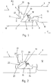
- FIG. 1 shows a cross section through two elements 1, 2 in the form of panels. This may be a head-side cross-section of the elements 1, 2.
- the elements 1, 2 are identically configured so that the elements 1, 2 can be assembled into a floor covering.
- FIG. 1 shows two adjacent elements 1, 2 before their locking.
- the representation in the image plane left shows a first element 1 and in the Image plane on the right a second element 2, which is intended to be connected to the first element 1.
- the first element 1 has a locking strip 3 and the second element 2 a downwardly open dome channel 4 and an adjoining downwardly directed end dome bulge 5.
- the locking strip 3 of the first element 1 protrudes from a head side 6.
- the element 2 is arranged relative to the element 1, that when lowering in the direction of arrow P dome 5 of the second panel in a dome channel 7 of the locking bar 3 and the dome channel 4 of the second element 2 with the dome 8 of the locking bar 3 of the first element 1 in Intervention arrived.
- This area of the elements 1, 2 essentially serves for positional orientation in the horizontal plane, horizontally in the context of the invention corresponding to the laying plane V, which coincides with the mutually parallel upper sides 9 and lower sides 10 of the elements 1, 2.
- the spring element 11 is an obliquely downwardly directed tongue in this illustration.
- oblique means starting from a connection region of the spring element 11 with a core 12 of the element 2 to a head side 13 of the second element 2 and an underside 10 of the second element 2.
- the inclination or inclination relative to the laying plane V in this embodiment is 53 °. It is preferably between 40 ° and 70 °, in particular between 50 ° and 60 °.
- an upper side 14 of the spring element 11 is designed as a flat surface.
- An underside 15 of the spring element 11 has a convex curvature.
- At a side facing the core 12 of the element 2 back 16 of the spring element 11 is an open to the bottom 10 of the element 2 free space 17 connects. In this free space 17, an elastic material 18 is arranged, which connects the spring element 11 with the core 12 elastically.
- the spring element 11 is an integral part of the element 2, wherein a transition region from the core 12 of the element 2 to the spring element 11 as a predetermined breaking point 19th is configured. Above the predetermined breaking point 19, a cutout 20 is arranged. The cutout 20 is delimited in the direction of the head side 13 of the element 2 by an attachment strip 21 pointing to the underside 10 of the element 2 ( FIG. 2 ). The cutout 20 above the predetermined breaking point 19 can be produced in one step by cutting out the upper side 14 of the spring element 11.
- the free cut 20 can absorb material released in the event of failure and, in particular, breakage of the predetermined breaking point 19.
- the element 1 has on its head side 6 a parallel to the laying plane V opposite the head side 6 protruding locking edge 22.
- an adjoining the locking edge 22 bottom 23 extends in the embodiment shown here parallel to a support surface 24 of the locking bar.
- the spring element 11 rests with a first region of its convex underside 15 on the support surface 24 of the locking strip 3. It can be seen that the spring element 11 can be guided past the projecting locking edge 22 without being clamped.
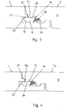
- FIG. 2 represents the lowering of the element 2 relative to the element 1 in the direction of arrow P.
- the spring element 11 slides with its underside 15 along the support surface 24 and remains due to the convex curvature during the joining operation with the support surface 24 in contact.
- the elastic material 18 is deformed in the rear free space 17 of the spring element 11.
- the spring element 11 is pivoted in the direction of the adjacent element 1.
- FIG. 3 shows the locked state of the elements 1, 2.
- the spring element 11 rests with its upper side 14 on an underside 23 adjacent to the locking edge 22 of the element 1.
- the spring element 11 is separated by the breakage of the predetermined breaking point 19 from the core 12 of the element 2. This is a brittle fracture.
- the predetermined breaking point 19 is configured so that the break at the transition from the in FIG. 2 position shown to the in FIG. 3 position shown.
- the spring element 11 is connected in the locking position only via the elastic material 18 with the core 12 of the element 2.
- the predetermined breaking point 19 adjacent undercut 20 is used to accommodate any breakage between core 12 and spring element 11 freed fragments.
- a downwardly facing contact surface 25 of the contact strip 21 abuts in the locking position on a horizontally oriented upper side 14 of the spring element 11, whereby an additional vertical support of the elements 1, 2 is achieved.
- the dome 5 is arranged almost completely behind the dome bulge 8 of the locking bar 3, so that a secure locking in the horizontal plane is ensured.
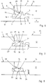
- FIG. 4 shows a cross section through a connecting region of two adjacent elements 1, 2a in an alternative embodiment of the second element 2a.
- no cutout is provided above the element 11a and the predetermined breaking point 19, so that in the illustrated locking position, the spring element 11a rests with its upper side 14 over a larger area than in the first embodiment on a downward facing, directly adjoining the predetermined breaking point 19 bearing surface 26.
- a further lowering of the second element 2a is not possible because the second element 2a is additionally supported on a bracket 27 of the first element 1.
- FIG. 5 shows a cross section through a connecting region of two adjacent elements 1, 2b before their locking.
- a predetermined breaking notch 28 is provided on the upper side 14 of the spring element 11 b in the region of the predetermined breaking point 19.
- This predetermined breaking notch 28 serves to selectively weaken the structure and, when connecting the elements 1, 2b to a break between the core 12 and spring element 11 b.
- the predetermined breaking notch 28 can absorb released material when it breaks.
- FIGS. 6 to 8 shown assembly positions of two adjacent elements and the reference numerals used correspond substantially to the illustrations of FIGS. 1 to 3 ,
- the spring element 11 c differs at the core of the element 2 c of the in the FIGS. 1 to 5 shown spring elements in that an elastic material 18 is arranged in a joint 29 on the head side 13 of the element 2 and not in a rear free space 17 of the spring element 11 c.
- the element 2c is arranged opposite to the element 1, that when lowering in the direction of arrow P analogous to FIG. 1 , the coupling bead 5 of the second element 2c engages a coupling channel 7 of the locking strip 3 and the coupling channel 4 of the second element 2c engages with the dome bead 8 of the locking strip 3 of the first element 1.
- this essentially serves for positional orientation in the horizontal laying plane V.
- the obliquely downwardly directed tongue of the spring element 11c also extends from a connection region of the spring element 11c with a core 12 of the element 2c to a head side 13 and an underside 10 of the second element 2c.
- An underside 15 of the spring element 11 c here also has a convex curvature, to which a planar area 30 adjoins. At this flat region 30 is followed by a substantially planar rear side 31 of the spring element 11c. Between the back 31 and the core 12 of the element 2 c, the free space 17 is arranged.
- the spring element 11 c is an integral part of the element 2 c, wherein a transition region from the core 12 of the element 2 c to the spring element 11 c is designed as a predetermined breaking point 19.
- FIG. 7 shows the lowering of the element 2c relative to the element 1 in the direction of arrow P.
- the spring element 11c slides with its underside 15 along the support surface 24 and remains due to the convex curvature during the joining operation with the support surface 24, as in FIG. 2 also shown, in contact.
- the elastic material 18 in the front-side joint 29 of the spring element 11 c is compressed or squeezed.
- the spring element 11 c is pivoted in the direction of the adjacent element 1 and the material in the region of the predetermined breaking point 19 to the breaking point and during further lowering beyond stretched.
- FIG. 8 shows the locked state of the elements 1, 2c.
- the spring element 11c abuts with its upper side 14 on an underside 23 next to the locking edge 22 of the element 1.
- the spring element 11c is separated by the breakage of the predetermined breaking point 19 from the core 12 of the element 2c.
- the flat portion 30 of the bottom 15 of the spring element 11 c is aligned in the locking position parallel to a support surface 24 of the element 1.
- the top 14 of the spring element 11 c is aligned parallel to the bottom 23 of the locking edge 22 and is applied to this.
Priority Applications (1)
| Application Number | Priority Date | Filing Date | Title |
|---|---|---|---|
| PL10779208T PL2483496T3 (pl) | 2009-10-02 | 2010-09-15 | Pokrycie z elementów łączonych ze sobą mechanicznie |
Applications Claiming Priority (2)
| Application Number | Priority Date | Filing Date | Title |
|---|---|---|---|
| DE102009048050A DE102009048050B3 (de) | 2009-10-02 | 2009-10-02 | Belag aus mechanischen miteinander verbindbaren Elementen |
| PCT/DE2010/001089 WO2011038709A1 (de) | 2009-10-02 | 2010-09-15 | Belag aus mechanischen miteinander verbindbaren elementen |
Publications (2)
| Publication Number | Publication Date |
|---|---|
| EP2483496A1 EP2483496A1 (de) | 2012-08-08 |
| EP2483496B1 true EP2483496B1 (de) | 2017-07-12 |
Family
ID=43382986
Family Applications (1)
| Application Number | Title | Priority Date | Filing Date |
|---|---|---|---|
| EP10779208.7A Active EP2483496B1 (de) | 2009-10-02 | 2010-09-15 | Belag aus mechanisch miteinander verbindbaren elementen |
Country Status (6)
| Country | Link |
|---|---|
| US (1) | US8752352B2 (ru) |
| EP (1) | EP2483496B1 (ru) |
| DE (1) | DE102009048050B3 (ru) |
| PL (1) | PL2483496T3 (ru) |
| RU (1) | RU2501923C1 (ru) |
| WO (1) | WO2011038709A1 (ru) |
Families Citing this family (56)
| Publication number | Priority date | Publication date | Assignee | Title |
|---|---|---|---|---|
| WO2010087752A1 (en) * | 2009-01-30 | 2010-08-05 | Välinge Innovation Belgium BVBA | Mechanical lockings of floor panels and a tongue blank |
| DE102009034903B3 (de) * | 2009-07-27 | 2011-01-20 | Guido Schulte | Belag aus mechanisch miteinander verbindbaren Paneelen |
| PL2524093T3 (pl) | 2010-01-12 | 2020-07-27 | Välinge Innovation AB | Mechaniczny układ blokujący dla paneli podłogowych |
| EP3524754B1 (en) | 2010-01-14 | 2020-10-28 | Unilin, BV | Floor panel assembly |
| BR112012018285B1 (pt) | 2010-02-04 | 2020-02-18 | Välinge Innovation AB | Conjunto de painéis de piso |
| DE102010012572B3 (de) * | 2010-03-23 | 2011-07-14 | Fritz Egger Gmbh & Co. Og | System von wenigstens zwei Paneelen |
| DE212010000195U1 (de) | 2010-04-15 | 2012-08-06 | Spanolux N.V. Div. Balterio | Bodenplattenanordnung |
| US8806832B2 (en) | 2011-03-18 | 2014-08-19 | Inotec Global Limited | Vertical joint system and associated surface covering system |
| UA109938C2 (uk) | 2011-05-06 | 2015-10-26 | Механічна фіксуюча система для будівельних панелей | |
| UA114715C2 (uk) | 2011-07-05 | 2017-07-25 | Сералок Інновейшн Аб | Механічна фіксація панелей настилу підлоги до язичка з нанесеним шаром клею |
| US9725912B2 (en) | 2011-07-11 | 2017-08-08 | Ceraloc Innovation Ab | Mechanical locking system for floor panels |
| US8650826B2 (en) | 2011-07-19 | 2014-02-18 | Valinge Flooring Technology Ab | Mechanical locking system for floor panels |
| US8857126B2 (en) | 2011-08-15 | 2014-10-14 | Valinge Flooring Technology Ab | Mechanical locking system for floor panels |
| US8763340B2 (en) | 2011-08-15 | 2014-07-01 | Valinge Flooring Technology Ab | Mechanical locking system for floor panels |
| US8769905B2 (en) | 2011-08-15 | 2014-07-08 | Valinge Flooring Technology Ab | Mechanical locking system for floor panels |
| US9216541B2 (en) | 2012-04-04 | 2015-12-22 | Valinge Innovation Ab | Method for producing a mechanical locking system for building panels |
| EP2855795B1 (en) * | 2012-04-04 | 2017-06-28 | Välinge Innovation AB | Method for producing a mechanical locking system for building panels |
| US8596013B2 (en) | 2012-04-04 | 2013-12-03 | Valinge Innovation Ab | Building panel with a mechanical locking system |
| LT2852722T (lt) * | 2012-04-04 | 2017-08-10 | Välinge Innovation AB | Statybinė plokštė su mechanine fiksavimo sistema |
| DE102012107469A1 (de) | 2012-08-15 | 2014-02-20 | Guido Schulte | Belag aus mechanisch miteinander verbindbaren Elementen |
| PL2923012T3 (pl) | 2012-11-22 | 2020-04-30 | Ceraloc Innovation Ab | Mechaniczny układ blokujący dla paneli podłogowych |
| DE102013100345B4 (de) | 2013-01-14 | 2023-07-06 | Guido Schulte | Belag aus mechanisch miteinander verbindbaren Elementen |
| US9194134B2 (en) | 2013-03-08 | 2015-11-24 | Valinge Innovation Ab | Building panels provided with a mechanical locking system |
| ES2673421T3 (es) | 2013-03-25 | 2018-06-21 | Välinge Innovation AB | Tableros de suelo provistos de un sistema de bloqueo mecánico y método para producir tal sistema de bloqueo |
| JP6397009B2 (ja) | 2013-06-27 | 2018-10-10 | ベーリンゲ、イノベイション、アクチボラグVaelinge Innovation Ab | 機械式係止システムを持つ建材パネル |
| BR112015032687B1 (pt) | 2013-07-09 | 2022-03-15 | Ceraloc Innovation Ab | Conjunto de painéis de piso |
| DE102013112550A1 (de) * | 2013-08-07 | 2015-02-12 | Hamberger Industriewerke Gmbh | Verbindung für plattenförmige Bauelemente |
| CA2926336C (en) | 2013-10-25 | 2022-07-05 | Floor Iptech Ab | Mechanical locking system for floor panels |
| DE102013113125A1 (de) | 2013-11-27 | 2015-05-28 | Guido Schulte | Fußboden-, Wand- oder Deckenpaneel und Verfahren zu dessen Herstellung |
| DE102013113109A1 (de) | 2013-11-27 | 2015-06-11 | Guido Schulte | Fußbodendiele |
| DE102013113130B4 (de) | 2013-11-27 | 2022-01-27 | Välinge Innovation AB | Verfahren zur Herstellung einer Fußbodendiele |
| HRP20231029T1 (hr) | 2014-01-10 | 2023-12-22 | Välinge Innovation AB | Ploča na bazi drvenih vlakana s površinskim slojem |
| KR102398462B1 (ko) | 2014-03-24 | 2022-05-13 | 플로어링 인더스트리즈 리미티드 에스에이알엘 | 상호 로킹 가능한 패널의 세트 |
| US9260870B2 (en) | 2014-03-24 | 2016-02-16 | Ivc N.V. | Set of mutually lockable panels |
| WO2015174909A1 (en) | 2014-05-12 | 2015-11-19 | Välinge Innovation AB | A method of producing a veneered element and such a veneered element |
| US10246883B2 (en) | 2014-05-14 | 2019-04-02 | Valinge Innovation Ab | Building panel with a mechanical locking system |
| KR102386246B1 (ko) | 2014-05-14 | 2022-04-12 | 뵈린게 이노베이션 에이비이 | 기계식 록킹 시스템이 구비된 빌딩 패널 |
| EP3567184B1 (en) | 2014-08-29 | 2022-12-28 | Välinge Innovation AB | Vertical joint system for a surface covering panel |
| DE102014112529A1 (de) * | 2014-09-01 | 2016-03-03 | Guido Schulte | Mechanische Verbindung für Paneele und Verfahren zur Montage einer Verriegelungsfeder in einem Paneel |
| US10138636B2 (en) | 2014-11-27 | 2018-11-27 | Valinge Innovation Ab | Mechanical locking system for floor panels |
| CN110644720B (zh) | 2014-12-22 | 2022-03-04 | 塞拉洛克创新股份有限公司 | 用于地板镶板的机械锁定系统 |
| CN107208426B (zh) | 2015-01-16 | 2019-07-26 | 塞拉洛克创新股份有限公司 | 用于地板镶板的机械锁定系统 |
| EP3310580A4 (en) | 2015-06-16 | 2019-02-13 | Välinge Innovation AB | METHOD FOR PRODUCING A BUILDING PLATE OR A SURFACE AREA ELEMENT AND SUCH A BUILDING PLATE AND SURFACE ELEMENT |
| CN108368704A (zh) | 2015-12-17 | 2018-08-03 | 瓦林格创新股份有限公司 | 用于制造用于镶板的机械锁定系统的方法 |
| DE102016105463B4 (de) | 2016-03-23 | 2023-03-30 | Guido Schulte | Mechanische Verbindung für Paneele |
| PL3448674T3 (pl) | 2016-04-25 | 2021-08-02 | Välinge Innovation AB | Element fornirowany i sposób wytwarzania takiego elementu fornirowanego |
| MX2019003403A (es) | 2016-09-30 | 2019-05-30 | Vaelinge Innovation Ab | Conjunto de paneles armados mediante desplazamiento vertical y asegurados unos con otros en la direccion vertical y horizontal. |
| US10400458B1 (en) * | 2017-02-10 | 2019-09-03 | David W Moeller | Interlocking flooring system using locking strips |
| EP3737802B1 (en) | 2018-01-09 | 2023-05-10 | Välinge Innovation AB | Set of panels |
| WO2019139523A1 (en) | 2018-01-11 | 2019-07-18 | Välinge Innovation AB | A method to produce a veneered element and a veneered element |
| PL3737559T3 (pl) | 2018-01-11 | 2024-01-22 | Välinge Innovation AB | Sposób wykonania elementu fornirowanego i element fornirowany |
| BR112020025052A2 (pt) | 2018-06-13 | 2021-03-23 | Ceraloc Innovation Ab | sistema de piso fornecido com um sistema de conexão e um dispositivo de conexão associado |
| WO2020145870A1 (en) | 2019-01-09 | 2020-07-16 | Välinge Innovation AB | A method to produce a veneer element and a veneer element |
| KR20210110687A (ko) | 2019-01-10 | 2021-09-08 | 뵈린게 이노베이션 에이비이 | 수직으로 잠금해제될 수 있는 패널들의 세트, 이의 방법 및 디바이스 |
| CN114375358A (zh) * | 2019-09-23 | 2022-04-19 | 地板工业有限公司 | 地板或墙壁覆盖件 |
| EP4135982A1 (en) | 2020-04-16 | 2023-02-22 | Välinge Innovation AB | A method for producing a building element, a pressing device and a method of embossing a wooden surface |
Family Cites Families (16)
| Publication number | Priority date | Publication date | Assignee | Title |
|---|---|---|---|---|
| DE20122553U1 (de) * | 2001-08-10 | 2006-03-23 | Akzenta Paneele + Profile Gmbh | Paneel sowie Befestigungssystem für Paneele |
| DE50311595D1 (de) * | 2002-04-05 | 2009-07-30 | Tilo Gmbh | Fussbodendielen |
| DE10231921A1 (de) * | 2002-06-28 | 2004-01-22 | E.F.P. Floor Products Fussböden GmbH | Paneel eines Fußbodensystems, insbesondere eines Laminatfußbodens |
| DE102004001363A1 (de) * | 2004-01-07 | 2005-08-04 | Hamberger Industriewerke Gmbh | Verbindung für Fußbodenelemente |
| SE529076C2 (sv) * | 2005-07-11 | 2007-04-24 | Pergo Europ Ab | En fog till paneler |
| DE202007017602U1 (de) * | 2006-08-10 | 2008-04-03 | Schulte, Guido | Fußbodenbelag |
| DE102007015048B4 (de) * | 2007-03-26 | 2009-03-05 | Kronotec Ag | Paneel, insbesondere Bodenpaneel |
| US8220217B2 (en) * | 2007-07-20 | 2012-07-17 | Innovaris Ag | Flooring system |
| US7726088B2 (en) * | 2007-07-20 | 2010-06-01 | Moritz Andre Muehlebach | Flooring system |
| DE102007042250B4 (de) * | 2007-09-06 | 2010-04-22 | Flooring Technologies Ltd. | Einrichtung zur Verbindung und Verriegelung zweier Bauplatten, insbesondere Fussbodenpaneele |
| DE102007043308B4 (de) * | 2007-09-11 | 2009-12-03 | Flooring Technologies Ltd. | Einrichtung zur Verbindung und Verriegelung zweier Bauplatten, insbesondere Fussbodenpaneele |
| BE1018600A5 (nl) * | 2007-11-23 | 2011-04-05 | Flooring Ind Ltd Sarl | Vloerpaneel. |
| DE102008030281B3 (de) | 2008-06-30 | 2009-10-29 | Guido Schulte | Verfahren und Vorrichtung zum Einsetzen von Federn in eine Nut |
| PL2226447T3 (pl) * | 2009-02-27 | 2012-10-31 | Vaelinge Innovation Ab | Panel, zwłaszcza panel podłogowy |
| DE102009035275A1 (de) | 2009-06-08 | 2010-12-09 | Fritz Egger Gmbh & Co. | Paneel eines Fußbodensystems |
| BE1018802A3 (nl) * | 2009-06-29 | 2011-09-06 | Flooring Ind Ltd Sarl | Paneel, meer speciaal vloerpaneel. |
-
2009
- 2009-10-02 DE DE102009048050A patent/DE102009048050B3/de active Active
-
2010
- 2010-09-15 US US13/499,804 patent/US8752352B2/en active Active
- 2010-09-15 RU RU2012117221/03A patent/RU2501923C1/ru active
- 2010-09-15 EP EP10779208.7A patent/EP2483496B1/de active Active
- 2010-09-15 PL PL10779208T patent/PL2483496T3/pl unknown
- 2010-09-15 WO PCT/DE2010/001089 patent/WO2011038709A1/de active Application Filing
Non-Patent Citations (1)
| Title |
|---|
| None * |
Also Published As
| Publication number | Publication date |
|---|---|
| WO2011038709A1 (de) | 2011-04-07 |
| DE102009048050B3 (de) | 2011-01-20 |
| US8752352B2 (en) | 2014-06-17 |
| PL2483496T3 (pl) | 2017-12-29 |
| EP2483496A1 (de) | 2012-08-08 |
| RU2012117221A (ru) | 2013-11-10 |
| US20120192521A1 (en) | 2012-08-02 |
| RU2501923C1 (ru) | 2013-12-20 |
Similar Documents
| Publication | Publication Date | Title |
|---|---|---|
| EP2483496B1 (de) | Belag aus mechanisch miteinander verbindbaren elementen | |
| DE102009041297B4 (de) | Belag aus mechanisch miteinander verbindbaren Elementen und ein Verfahren zur Herstellung von Elementen | |
| DE10206877B4 (de) | Paneel, insbesondere Fussbodenpaneel | |
| DE102005010565C5 (de) | Leichtbauplatte und Verfahren zu ihrer Herstellung | |
| EP1527241B1 (de) | Vorrichtung zum verbinden von zwei plattenförmigen paneelen | |
| EP1294995B1 (de) | Fussbodensystem mit mehreren gleichen Fussbodenplatten | |
| EP2037128B1 (de) | Einrichtung zur Verbindung und Verriegelung zweier Bauplatten | |
| DE102008021970B4 (de) | Paneel mit vereinfachtem Rastelement | |
| EP2459815B1 (de) | Belag aus mechanisch miteinander verbindbaren paneelen | |
| DE102010012572B3 (de) | System von wenigstens zwei Paneelen | |
| EP1380710B1 (de) | Fussbodenpaneel und Verfahren zum Verlegen eines Fussbodens | |
| EP2459818A2 (de) | Belag aus mechanisch miteinander verbindbaren paneelen | |
| EP1980683A2 (de) | Paneel, insbesondere Bodenpaneel | |
| DE60100600T2 (de) | Befestigungsvorrichtung für die längsränder von platten, latten oder wandverkleidungen mit kraftverteilung | |
| DE202010017748U1 (de) | Belag aus mechanisch miteinander verbindbaren Elementen | |
| DE102013100345B4 (de) | Belag aus mechanisch miteinander verbindbaren Elementen | |
| EP2795016B1 (de) | Paneel eines fussbodenbelags mit fremdelement | |
| WO2013023639A1 (de) | Belag aus mechanisch miteinander verbindbaren paneelen | |
| DE102016105463B4 (de) | Mechanische Verbindung für Paneele | |
| WO2016146112A1 (de) | Mechanische verbindung für paneele und verfahren zur herstellung von verbindungsmitteln | |
| DE10253236B4 (de) | Fussbodenpaneel und Verfahren zum Verlegen eines Fussbodenpaneels | |
| EP2885470A1 (de) | Belag aus mechanisch miteinander verbindbaren elementen | |
| EP3670783B1 (de) | Montageclip zur schwimmenden lagerung von wand- und deckenpaneelen | |
| DE102007046598B4 (de) | Paneel | |
| DE102010022290B4 (de) | Fußboden-, Wand- oder Deckenelement |
Legal Events
| Date | Code | Title | Description |
|---|---|---|---|
| PUAI | Public reference made under article 153(3) epc to a published international application that has entered the european phase |
Free format text: ORIGINAL CODE: 0009012 |
|
| 17P | Request for examination filed |
Effective date: 20120228 |
|
| AK | Designated contracting states |
Kind code of ref document: A1 Designated state(s): AL AT BE BG CH CY CZ DE DK EE ES FI FR GB GR HR HU IE IS IT LI LT LU LV MC MK MT NL NO PL PT RO SE SI SK SM TR |
|
| DAX | Request for extension of the european patent (deleted) | ||
| GRAP | Despatch of communication of intention to grant a patent |
Free format text: ORIGINAL CODE: EPIDOSNIGR1 |
|
| INTG | Intention to grant announced |
Effective date: 20170316 |
|
| GRAS | Grant fee paid |
Free format text: ORIGINAL CODE: EPIDOSNIGR3 |
|
| GRAA | (expected) grant |
Free format text: ORIGINAL CODE: 0009210 |
|
| AK | Designated contracting states |
Kind code of ref document: B1 Designated state(s): AL AT BE BG CH CY CZ DE DK EE ES FI FR GB GR HR HU IE IS IT LI LT LU LV MC MK MT NL NO PL PT RO SE SI SK SM TR |
|
| REG | Reference to a national code |
Ref country code: GB Ref legal event code: FG4D Free format text: NOT ENGLISH |
|
| REG | Reference to a national code |
Ref country code: CH Ref legal event code: EP |
|
| REG | Reference to a national code |
Ref country code: AT Ref legal event code: REF Ref document number: 908487 Country of ref document: AT Kind code of ref document: T Effective date: 20170715 |
|
| REG | Reference to a national code |
Ref country code: IE Ref legal event code: FG4D Free format text: LANGUAGE OF EP DOCUMENT: GERMAN |
|
| REG | Reference to a national code |
Ref country code: DE Ref legal event code: R096 Ref document number: 502010013858 Country of ref document: DE |
|
| REG | Reference to a national code |
Ref country code: FR Ref legal event code: PLFP Year of fee payment: 8 |
|
| REG | Reference to a national code |
Ref country code: NL Ref legal event code: MP Effective date: 20170712 |
|
| REG | Reference to a national code |
Ref country code: LT Ref legal event code: MG4D |
|
| PG25 | Lapsed in a contracting state [announced via postgrant information from national office to epo] |
Ref country code: NO Free format text: LAPSE BECAUSE OF FAILURE TO SUBMIT A TRANSLATION OF THE DESCRIPTION OR TO PAY THE FEE WITHIN THE PRESCRIBED TIME-LIMIT Effective date: 20171012 Ref country code: HR Free format text: LAPSE BECAUSE OF FAILURE TO SUBMIT A TRANSLATION OF THE DESCRIPTION OR TO PAY THE FEE WITHIN THE PRESCRIBED TIME-LIMIT Effective date: 20170712 Ref country code: SE Free format text: LAPSE BECAUSE OF FAILURE TO SUBMIT A TRANSLATION OF THE DESCRIPTION OR TO PAY THE FEE WITHIN THE PRESCRIBED TIME-LIMIT Effective date: 20170712 Ref country code: NL Free format text: LAPSE BECAUSE OF FAILURE TO SUBMIT A TRANSLATION OF THE DESCRIPTION OR TO PAY THE FEE WITHIN THE PRESCRIBED TIME-LIMIT Effective date: 20170712 Ref country code: FI Free format text: LAPSE BECAUSE OF FAILURE TO SUBMIT A TRANSLATION OF THE DESCRIPTION OR TO PAY THE FEE WITHIN THE PRESCRIBED TIME-LIMIT Effective date: 20170712 Ref country code: LT Free format text: LAPSE BECAUSE OF FAILURE TO SUBMIT A TRANSLATION OF THE DESCRIPTION OR TO PAY THE FEE WITHIN THE PRESCRIBED TIME-LIMIT Effective date: 20170712 |
|
| PG25 | Lapsed in a contracting state [announced via postgrant information from national office to epo] |
Ref country code: ES Free format text: LAPSE BECAUSE OF FAILURE TO SUBMIT A TRANSLATION OF THE DESCRIPTION OR TO PAY THE FEE WITHIN THE PRESCRIBED TIME-LIMIT Effective date: 20170712 Ref country code: BG Free format text: LAPSE BECAUSE OF FAILURE TO SUBMIT A TRANSLATION OF THE DESCRIPTION OR TO PAY THE FEE WITHIN THE PRESCRIBED TIME-LIMIT Effective date: 20171012 Ref country code: IS Free format text: LAPSE BECAUSE OF FAILURE TO SUBMIT A TRANSLATION OF THE DESCRIPTION OR TO PAY THE FEE WITHIN THE PRESCRIBED TIME-LIMIT Effective date: 20171112 Ref country code: LV Free format text: LAPSE BECAUSE OF FAILURE TO SUBMIT A TRANSLATION OF THE DESCRIPTION OR TO PAY THE FEE WITHIN THE PRESCRIBED TIME-LIMIT Effective date: 20170712 Ref country code: GR Free format text: LAPSE BECAUSE OF FAILURE TO SUBMIT A TRANSLATION OF THE DESCRIPTION OR TO PAY THE FEE WITHIN THE PRESCRIBED TIME-LIMIT Effective date: 20171013 |
|
| REG | Reference to a national code |
Ref country code: DE Ref legal event code: R097 Ref document number: 502010013858 Country of ref document: DE |
|
| PG25 | Lapsed in a contracting state [announced via postgrant information from national office to epo] |
Ref country code: DK Free format text: LAPSE BECAUSE OF FAILURE TO SUBMIT A TRANSLATION OF THE DESCRIPTION OR TO PAY THE FEE WITHIN THE PRESCRIBED TIME-LIMIT Effective date: 20170712 Ref country code: CZ Free format text: LAPSE BECAUSE OF FAILURE TO SUBMIT A TRANSLATION OF THE DESCRIPTION OR TO PAY THE FEE WITHIN THE PRESCRIBED TIME-LIMIT Effective date: 20170712 Ref country code: RO Free format text: LAPSE BECAUSE OF FAILURE TO SUBMIT A TRANSLATION OF THE DESCRIPTION OR TO PAY THE FEE WITHIN THE PRESCRIBED TIME-LIMIT Effective date: 20170712 |
|
| REG | Reference to a national code |
Ref country code: CH Ref legal event code: PL |
|
| PLBE | No opposition filed within time limit |
Free format text: ORIGINAL CODE: 0009261 |
|
| STAA | Information on the status of an ep patent application or granted ep patent |
Free format text: STATUS: NO OPPOSITION FILED WITHIN TIME LIMIT |
|
| PG25 | Lapsed in a contracting state [announced via postgrant information from national office to epo] |
Ref country code: EE Free format text: LAPSE BECAUSE OF FAILURE TO SUBMIT A TRANSLATION OF THE DESCRIPTION OR TO PAY THE FEE WITHIN THE PRESCRIBED TIME-LIMIT Effective date: 20170712 Ref country code: MC Free format text: LAPSE BECAUSE OF FAILURE TO SUBMIT A TRANSLATION OF THE DESCRIPTION OR TO PAY THE FEE WITHIN THE PRESCRIBED TIME-LIMIT Effective date: 20170712 Ref country code: IT Free format text: LAPSE BECAUSE OF FAILURE TO SUBMIT A TRANSLATION OF THE DESCRIPTION OR TO PAY THE FEE WITHIN THE PRESCRIBED TIME-LIMIT Effective date: 20170712 Ref country code: SM Free format text: LAPSE BECAUSE OF FAILURE TO SUBMIT A TRANSLATION OF THE DESCRIPTION OR TO PAY THE FEE WITHIN THE PRESCRIBED TIME-LIMIT Effective date: 20170712 Ref country code: SK Free format text: LAPSE BECAUSE OF FAILURE TO SUBMIT A TRANSLATION OF THE DESCRIPTION OR TO PAY THE FEE WITHIN THE PRESCRIBED TIME-LIMIT Effective date: 20170712 |
|
| 26N | No opposition filed |
Effective date: 20180413 |
|
| REG | Reference to a national code |
Ref country code: IE Ref legal event code: MM4A |
|
| REG | Reference to a national code |
Ref country code: BE Ref legal event code: MM Effective date: 20170930 |
|
| PG25 | Lapsed in a contracting state [announced via postgrant information from national office to epo] |
Ref country code: LU Free format text: LAPSE BECAUSE OF NON-PAYMENT OF DUE FEES Effective date: 20170915 |
|
| PG25 | Lapsed in a contracting state [announced via postgrant information from national office to epo] |
Ref country code: CH Free format text: LAPSE BECAUSE OF NON-PAYMENT OF DUE FEES Effective date: 20170930 Ref country code: IE Free format text: LAPSE BECAUSE OF NON-PAYMENT OF DUE FEES Effective date: 20170915 Ref country code: LI Free format text: LAPSE BECAUSE OF NON-PAYMENT OF DUE FEES Effective date: 20170930 |
|
| PG25 | Lapsed in a contracting state [announced via postgrant information from national office to epo] |
Ref country code: BE Free format text: LAPSE BECAUSE OF NON-PAYMENT OF DUE FEES Effective date: 20170930 Ref country code: SI Free format text: LAPSE BECAUSE OF FAILURE TO SUBMIT A TRANSLATION OF THE DESCRIPTION OR TO PAY THE FEE WITHIN THE PRESCRIBED TIME-LIMIT Effective date: 20170712 |
|
| REG | Reference to a national code |
Ref country code: FR Ref legal event code: PLFP Year of fee payment: 9 |
|
| PG25 | Lapsed in a contracting state [announced via postgrant information from national office to epo] |
Ref country code: MT Free format text: LAPSE BECAUSE OF FAILURE TO SUBMIT A TRANSLATION OF THE DESCRIPTION OR TO PAY THE FEE WITHIN THE PRESCRIBED TIME-LIMIT Effective date: 20170712 |
|
| REG | Reference to a national code |
Ref country code: AT Ref legal event code: MM01 Ref document number: 908487 Country of ref document: AT Kind code of ref document: T Effective date: 20170915 |
|
| PG25 | Lapsed in a contracting state [announced via postgrant information from national office to epo] |
Ref country code: AT Free format text: LAPSE BECAUSE OF NON-PAYMENT OF DUE FEES Effective date: 20170915 |
|
| PG25 | Lapsed in a contracting state [announced via postgrant information from national office to epo] |
Ref country code: HU Free format text: LAPSE BECAUSE OF FAILURE TO SUBMIT A TRANSLATION OF THE DESCRIPTION OR TO PAY THE FEE WITHIN THE PRESCRIBED TIME-LIMIT; INVALID AB INITIO Effective date: 20100915 |
|
| PG25 | Lapsed in a contracting state [announced via postgrant information from national office to epo] |
Ref country code: CY Free format text: LAPSE BECAUSE OF NON-PAYMENT OF DUE FEES Effective date: 20170712 |
|
| PG25 | Lapsed in a contracting state [announced via postgrant information from national office to epo] |
Ref country code: MK Free format text: LAPSE BECAUSE OF FAILURE TO SUBMIT A TRANSLATION OF THE DESCRIPTION OR TO PAY THE FEE WITHIN THE PRESCRIBED TIME-LIMIT Effective date: 20170712 |
|
| PG25 | Lapsed in a contracting state [announced via postgrant information from national office to epo] |
Ref country code: TR Free format text: LAPSE BECAUSE OF FAILURE TO SUBMIT A TRANSLATION OF THE DESCRIPTION OR TO PAY THE FEE WITHIN THE PRESCRIBED TIME-LIMIT Effective date: 20170712 |
|
| PG25 | Lapsed in a contracting state [announced via postgrant information from national office to epo] |
Ref country code: PT Free format text: LAPSE BECAUSE OF FAILURE TO SUBMIT A TRANSLATION OF THE DESCRIPTION OR TO PAY THE FEE WITHIN THE PRESCRIBED TIME-LIMIT Effective date: 20170712 |
|
| PG25 | Lapsed in a contracting state [announced via postgrant information from national office to epo] |
Ref country code: AL Free format text: LAPSE BECAUSE OF FAILURE TO SUBMIT A TRANSLATION OF THE DESCRIPTION OR TO PAY THE FEE WITHIN THE PRESCRIBED TIME-LIMIT Effective date: 20170712 |
|
| PGFP | Annual fee paid to national office [announced via postgrant information from national office to epo] |
Ref country code: GB Payment date: 20230920 Year of fee payment: 14 |
|
| PGFP | Annual fee paid to national office [announced via postgrant information from national office to epo] |
Ref country code: PL Payment date: 20230908 Year of fee payment: 14 Ref country code: FR Payment date: 20230928 Year of fee payment: 14 Ref country code: DE Payment date: 20230928 Year of fee payment: 14 |