EP2483496B1 - Belag aus mechanisch miteinander verbindbaren elementen - Google Patents
Belag aus mechanisch miteinander verbindbaren elementen Download PDFInfo
- Publication number
- EP2483496B1 EP2483496B1 EP10779208.7A EP10779208A EP2483496B1 EP 2483496 B1 EP2483496 B1 EP 2483496B1 EP 10779208 A EP10779208 A EP 10779208A EP 2483496 B1 EP2483496 B1 EP 2483496B1
- Authority
- EP
- European Patent Office
- Prior art keywords
- elements
- covering according
- tongue
- spring element
- locking
- Prior art date
- Legal status (The legal status is an assumption and is not a legal conclusion. Google has not performed a legal analysis and makes no representation as to the accuracy of the status listed.)
- Active
Links
- 239000013013 elastic material Substances 0.000 claims description 20
- 239000000853 adhesive Substances 0.000 claims description 6
- 230000001070 adhesive effect Effects 0.000 claims description 6
- 238000006073 displacement reaction Methods 0.000 claims description 4
- 239000004823 Reactive adhesive Substances 0.000 claims description 3
- 230000000295 complement effect Effects 0.000 claims 1
- 238000009434 installation Methods 0.000 claims 1
- 239000011162 core material Substances 0.000 description 34
- 239000000463 material Substances 0.000 description 12
- 238000004519 manufacturing process Methods 0.000 description 4
- 239000004033 plastic Substances 0.000 description 4
- 229920003023 plastic Polymers 0.000 description 4
- 230000008878 coupling Effects 0.000 description 3
- 238000010168 coupling process Methods 0.000 description 3
- 238000005859 coupling reaction Methods 0.000 description 3
- 230000007704 transition Effects 0.000 description 3
- 239000002023 wood Substances 0.000 description 3
- 239000011324 bead Substances 0.000 description 2
- 238000010276 construction Methods 0.000 description 2
- 238000011161 development Methods 0.000 description 2
- 230000018109 developmental process Effects 0.000 description 2
- 238000005516 engineering process Methods 0.000 description 2
- 239000000565 sealant Substances 0.000 description 2
- 239000004820 Pressure-sensitive adhesive Substances 0.000 description 1
- 150000001252 acrylic acid derivatives Chemical class 0.000 description 1
- 238000005452 bending Methods 0.000 description 1
- 230000015572 biosynthetic process Effects 0.000 description 1
- 238000006243 chemical reaction Methods 0.000 description 1
- 239000011093 chipboard Substances 0.000 description 1
- 239000007799 cork Substances 0.000 description 1
- 230000001419 dependent effect Effects 0.000 description 1
- 230000000694 effects Effects 0.000 description 1
- 229920001971 elastomer Polymers 0.000 description 1
- 239000000806 elastomer Substances 0.000 description 1
- 239000000835 fiber Substances 0.000 description 1
- 238000009408 flooring Methods 0.000 description 1
- 239000012634 fragment Substances 0.000 description 1
- 239000011440 grout Substances 0.000 description 1
- 229910052602 gypsum Inorganic materials 0.000 description 1
- 239000010440 gypsum Substances 0.000 description 1
- 239000012943 hotmelt Substances 0.000 description 1
- 239000007788 liquid Substances 0.000 description 1
- 239000002991 molded plastic Substances 0.000 description 1
- 238000000465 moulding Methods 0.000 description 1
- 239000000123 paper Substances 0.000 description 1
- 229920001296 polysiloxane Polymers 0.000 description 1
- 238000007789 sealing Methods 0.000 description 1
- 239000011343 solid material Substances 0.000 description 1
Images

Classifications
-
- F—MECHANICAL ENGINEERING; LIGHTING; HEATING; WEAPONS; BLASTING
- F16—ENGINEERING ELEMENTS AND UNITS; GENERAL MEASURES FOR PRODUCING AND MAINTAINING EFFECTIVE FUNCTIONING OF MACHINES OR INSTALLATIONS; THERMAL INSULATION IN GENERAL
- F16B—DEVICES FOR FASTENING OR SECURING CONSTRUCTIONAL ELEMENTS OR MACHINE PARTS TOGETHER, e.g. NAILS, BOLTS, CIRCLIPS, CLAMPS, CLIPS OR WEDGES; JOINTS OR JOINTING
- F16B5/00—Joining sheets or plates, e.g. panels, to one another or to strips or bars parallel to them
- F16B5/0004—Joining sheets, plates or panels in abutting relationship
- F16B5/0056—Joining sheets, plates or panels in abutting relationship by moving the sheets, plates or panels or the interlocking key perpendicular to the main plane
- F16B5/0076—Joining sheets, plates or panels in abutting relationship by moving the sheets, plates or panels or the interlocking key perpendicular to the main plane and using expanding clamps
-
- E—FIXED CONSTRUCTIONS
- E04—BUILDING
- E04F—FINISHING WORK ON BUILDINGS, e.g. STAIRS, FLOORS
- E04F13/00—Coverings or linings, e.g. for walls or ceilings
- E04F13/07—Coverings or linings, e.g. for walls or ceilings composed of covering or lining elements; Sub-structures therefor; Fastening means therefor
- E04F13/08—Coverings or linings, e.g. for walls or ceilings composed of covering or lining elements; Sub-structures therefor; Fastening means therefor composed of a plurality of similar covering or lining elements
-
- E—FIXED CONSTRUCTIONS
- E04—BUILDING
- E04F—FINISHING WORK ON BUILDINGS, e.g. STAIRS, FLOORS
- E04F15/00—Flooring
- E04F15/02—Flooring or floor layers composed of a number of similar elements
-
- E—FIXED CONSTRUCTIONS
- E04—BUILDING
- E04F—FINISHING WORK ON BUILDINGS, e.g. STAIRS, FLOORS
- E04F15/00—Flooring
- E04F15/02—Flooring or floor layers composed of a number of similar elements
- E04F15/024—Sectional false floors, e.g. computer floors
- E04F15/02405—Floor panels
-
- E—FIXED CONSTRUCTIONS
- E04—BUILDING
- E04F—FINISHING WORK ON BUILDINGS, e.g. STAIRS, FLOORS
- E04F2201/00—Joining sheets or plates or panels
- E04F2201/01—Joining sheets, plates or panels with edges in abutting relationship
- E04F2201/0138—Joining sheets, plates or panels with edges in abutting relationship by moving the sheets, plates or panels perpendicular to the main plane
- E04F2201/0146—Joining sheets, plates or panels with edges in abutting relationship by moving the sheets, plates or panels perpendicular to the main plane with snap action of the edge connectors
-
- E—FIXED CONSTRUCTIONS
- E04—BUILDING
- E04F—FINISHING WORK ON BUILDINGS, e.g. STAIRS, FLOORS
- E04F2201/00—Joining sheets or plates or panels
- E04F2201/01—Joining sheets, plates or panels with edges in abutting relationship
- E04F2201/0169—Joining sheets, plates or panels with edges in abutting relationship by rotating the sheets, plates or panels around an axis which is perpendicular to the abutting edges and parallel to the main plane, possibly combined with a sliding movement
- E04F2201/0176—Joining sheets, plates or panels with edges in abutting relationship by rotating the sheets, plates or panels around an axis which is perpendicular to the abutting edges and parallel to the main plane, possibly combined with a sliding movement with snap action of the edge connectors
-
- E—FIXED CONSTRUCTIONS
- E04—BUILDING
- E04F—FINISHING WORK ON BUILDINGS, e.g. STAIRS, FLOORS
- E04F2201/00—Joining sheets or plates or panels
- E04F2201/04—Other details of tongues or grooves
- E04F2201/041—Tongues or grooves with slits or cuts for expansion or flexibility
-
- E—FIXED CONSTRUCTIONS
- E04—BUILDING
- E04F—FINISHING WORK ON BUILDINGS, e.g. STAIRS, FLOORS
- E04F2201/00—Joining sheets or plates or panels
- E04F2201/04—Other details of tongues or grooves
- E04F2201/044—Other details of tongues or grooves with tongues or grooves comprising elements which are not manufactured in one piece with the sheets, plates or panels but which are permanently fixedly connected to the sheets, plates or panels, e.g. at the factory
- E04F2201/049—Other details of tongues or grooves with tongues or grooves comprising elements which are not manufactured in one piece with the sheets, plates or panels but which are permanently fixedly connected to the sheets, plates or panels, e.g. at the factory wherein the elements are made of organic plastics with or without reinforcements or filling materials
Definitions
- the invention relates to a covering of mechanically interconnectable elements.
- Wall, ceiling and floor coverings such as Prefabricated parquet, wooden floors or laminate floors consist of several rows of rectangular panels in their configuration.
- the panels have on a longitudinal side and on a head side continuous grooves and on the respective opposite longitudinal side or head side continuous springs, which are adapted to the grooves form-fitting manner. By connecting tongue and groove the panels are laid, the panels of two adjacent rows are offset from one another.
- a covering with mechanically connectable elements in the form of floor panels is known, which have on their opposite sides a corresponding profiling and are lockable on this.
- the locking is effected by an elastic spring element, which is articulated on one of the elements by a positive connection and is pivotable behind a locking edge extending in the horizontal direction of the adjacent panel.
- the spring element is connected in the initial position via a pressure-sensitive adhesive as a predetermined breaking point with the element.
- the predetermined breaking point fails during pivoting of the spring element.
- the production of a positive connection for defining the pivot point of the spring element is relatively complicated.
- the prior art is also the WO2004 / 003314 A1 to call, which relates to a floor system with panels, which are locked together at their side edges.
- the lock provides a one-piece arranged on the one panel, vertical spring element, which has on its side facing away from the other panel has a Elastizticiansnut, with an elastic means such.
- B is filled with a PVC adhesive.
- the spring element can be deflected laterally during locking and remains firmly connected to the panel even after locking. If the spring element were to break off, it would have to be held in position by the elastic means.
- due to the vertical orientation of the spring element would inevitably adjust a height offset between the panels.
- the invention is based on the object to show a covering of mechanically interconnectable elements, which can be locked securely with little effort and which is easy to produce.
- the covering according to the invention comprises elements that can be mechanically connected to one another, wherein at least one of the elements is a panel.
- the invention includes the possibility that one of the elements as a panel and the other element is designed as a frame member for a frame construction, for example, for raised floors.
- the following description of the invention relates to an embodiment in which the elements to be joined are panels.
- the elements have at their opposite sides of a mutually corresponding profiling, by means of which adjacent elements by a substantially vertical or pivoting joining movement in the horizontal direction and vertical direction are locked together.
- a mutually corresponding profiling by means of which adjacent elements by a substantially vertical or pivoting joining movement in the horizontal direction and vertical direction are locked together.
- the opposite, provided with a corresponding profiling in the sense of the present invention pages are in particular head sides of the elements.
- the profiling can in principle be provided on all sides, that is to say the top sides and the long sides, of the essentially rectangular elements.
- the locking is effected by at least one spring element which is connected to one of the elements for a regionally via an elastic material with a core of the element and on the other hand before the joining movement integral part of the element.
- the elastic material is introduced into a space between a core of the element facing back of the spring element and the core arranged free space.
- the spring element articulated in this way is pivotable in the joining movement behind a locking edge of the adjacent element extending essentially in the horizontal direction.
- the two elements Due to the fact that the locking edge extends substantially in the horizontal direction, the two elements against vertical displacement, i. perpendicular to the laying level, secured. Additional locking strips can be provided on the elements, in addition to the locking in the vertical direction, to effect the locks of the laying plane.
- the one-piece connection between the spring element and the element is configured as a predetermined breaking point, which is intended to fail during pivoting of the spring element, in particular to break.
- a predetermined breaking point which is intended to fail during pivoting of the spring element, in particular to break.
- pivoting or lowering of the spring element is thus preferably effected by the predetermined breaking point a targeted break between the spring element and the core of the element.
- the failure or breakage of the predetermined breaking point between spring element and core preferably takes place when first connecting two adjacent elements.
- the predetermined breaking point is configured so that when a certain load is exceeded a failure of the structure takes place precisely at this point to achieve the desired function, namely the displacement of the spring element.
- the failure is in particular a brittle fracture.
- failure can also occur in overstretching of the core material, i. H. exist in a permanent plastic deformation.
- the fracture mechanics depends on the material properties of the spring element, wherein the plastic deformation behavior depends, among other things, on the state of stress, the temperature, the type of load and the loading speed.
- breaking / breaking is used for the failure of the predetermined breaking point, regardless of whether it is a plastic deformation, a partial fracture or a complete brittle fracture.
- the spring element slides with its underside on one of the locking edge opposite support surface of the adjacent element.
- the spring element is due to a material-specific elasticity of the element, which allows a certain pivoting of the spring element relative to its starting position, without the material is plastically deformed, so yields or breaks, nor integral part of the element.
- the spring element Upon further lowering of the element, the spring element is further pivoted relative to its starting position.
- the spring element breaks off in the region of the predetermined breaking point quasi from the core, but at the same time remains connected to the core of the element via the elastic material.
- the failure of the predetermined breaking point ie in particular the break occurs as soon as the spring element engages in the horizontal position between a support surface and a bottom of the locking edge or shortly before, ie relatively late during the joining. If a break occurs before reaching the locking position, the breaking edge on the side of the core acts as an abutment, presses on the spring element-side breaking edge and thus causes the spring element to reach the locking position. In this case, the elastic material holds the spring element in position so that the broken edges are substantially opposite.
- a predetermined breaking notch can be provided for the targeted introduction of notch stresses and thus for the targeted positioning of the break point.
- the course of the breaklines can be at least partially influenced.
- the time of the break ie how far the spring element can be elastically pivoted out of its starting position before it breaks, can be determined.
- released material can be absorbed by the predetermined breaking notch.
- a cutout can also be arranged. This cutout can serve the recording of the break between the spring element and core possibly resulting material. Both the predetermined breaking notch and the free cut above the predetermined breaking point can be cut simultaneously with the contour of the spring element from the core, without increasing the production cost appreciably.
- the support surface, with which the spring element corresponds, is oriented substantially horizontally and lies opposite the locking edge.
- an underside of the locking edge to the support surface is parallel.
- the underside of the spring element which slides on the support surface when joining adjacent elements is preferably convex.
- an upper surface of the spring element is inclined prior to the joining movement, i. from the predetermined breaking point to the front and bottom of the element sloping down, formed. In the manufacture of the elements, the inclined upper side is cut free from the core after the elastic material has been introduced into the rear free space of the spring element.
- the spring element After joining, the spring element is in the locking position with its upper side against an underside of the locking edge in a substantially horizontal orientation.
- the elastic material is an adhesive, an elastomer, a reactive adhesive, a hot-melt or a permanently elastic sealing or grout.
- Reactive adhesive refers to adhesives that cure and set by chemical reactions. These sealants or sealants also include acrylates and silicones.
- the selection of the elastic material is of course dependent on the materials used for the elements in order to obtain a good adhesion between the elastic material and the element.
- the spring element configured according to the invention firstly does not have to overcome any spring force for locking in the sense that the spring element is pushed back by the adjacent side of the element. Instead, it is displaced exclusively in the direction of the adjacent element. The Spring element does not snap under the influence of a spring force behind the locking edge, but is forcibly pushed behind the locking edge.
- the spring element After failure, in particular the breakage of the predetermined breaking point, the spring element is connected only via the elastic material to the core.
- the elastic connection between spring element and core is configured so that it remains after the joining. If necessary, this connection makes it possible, despite breakage, to relocate the elements.
- the spring element can not automatically move back on the restoring forces of the elastic material, since it is held between the support surface and the underside of the locking edge.
- the spring element is in a state of self-locking and can not return to its original position without a foreign force, so that the elements are securely in the locked position, i. in the laying plane, are held.
- a friction-increasing profiling may preferably be provided on an underside of the locking edge and / or an upper side of the spring element.
- the spring elements can be arranged adjacent to each other or spaced apart.
- more than one spring element per side is arranged.
- spring elements of different elasticities can therefore also be arranged at a distance from each other.
- Manufacturing technology it is easiest if initially a single correspondingly long spring element is divided into individual sections. For this purpose, a plurality of slots can be formed in the originally single spring element, so that the individualized spring elements can be actuated in sequence when folding down.
- a connecting means may serve an elastic member, such. an elastic adhesive, as it also comes in the rear space of the spring element used.
- the elastic connection makes it possible to make the spring elements smaller, without the risk that solves a single spring element of the element in case of damage.
- the freedom of design is generally greater when the spring elements are additionally bonded together adhesive technology.
- the element having the locking edge has a locking strip under the element carrying the spring element.
- This locking bar is suitable and provided, the adjacent elements against tensile loads in one Secure laying level.
- the additional locking bar only horizontal tensile forces are absorbed, so tensile loads in the laying plane. This ensures that no joint gap remains at the top. The entry of liquid and dirt in any gaps is prevented.
- the locking strip can also serve, in particular for wall coverings, to be fastened to a substructure, in particular a wall-side substructure.
- the locking strip can be secured by a fastening means in the form of a clip on the substructure. It is also conceivable to screw, nail or staple the locking strip directly, i. without fixing additional clip.
- the inventive concept is applicable to all floor systems and wall systems in which a top covering on a support, which in particular is a wood-based panel, such. an MDF or chipboard, is arranged, such as real wood coverings, laminate, support with painted surfaces as top coat, linoleum, cork on support plates, etc. If the elements of HDF or MDF material, a predetermined breaking notch is helpful, but not absolutely necessary, because this material sets a clear fiber break.
- the cover layer can in particular consist of a decorative paper with overlay, which determines the appearance of the elements.
- a floor covering may thus be a parquet floor, a finished parquet floor, a real wood floor or a laminate floor.
- elements of solid materials such as wooden planks, wooden elements, molded plastic mold plates, plastics, moldings or gypsum boards are suitable.
- the inventive concept not only relates to the joining of elements, but it is, as mentioned above, also conceivable to perform an element as a frame member for frame floors or raised floors.
- an element in such an application is one of the elements to be connected as a panel and a second element configured as a frame member.
- the panel is placed in the assembly of one or more frame members existing frame construction during assembly and locked with his head and / or sides.
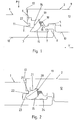
- FIG. 1 shows a cross section through two elements 1, 2 in the form of panels. This may be a head-side cross-section of the elements 1, 2.
- the elements 1, 2 are identically configured so that the elements 1, 2 can be assembled into a floor covering.
- FIG. 1 shows two adjacent elements 1, 2 before their locking.
- the representation in the image plane left shows a first element 1 and in the Image plane on the right a second element 2, which is intended to be connected to the first element 1.
- the first element 1 has a locking strip 3 and the second element 2 a downwardly open dome channel 4 and an adjoining downwardly directed end dome bulge 5.
- the locking strip 3 of the first element 1 protrudes from a head side 6.
- the element 2 is arranged relative to the element 1, that when lowering in the direction of arrow P dome 5 of the second panel in a dome channel 7 of the locking bar 3 and the dome channel 4 of the second element 2 with the dome 8 of the locking bar 3 of the first element 1 in Intervention arrived.
- This area of the elements 1, 2 essentially serves for positional orientation in the horizontal plane, horizontally in the context of the invention corresponding to the laying plane V, which coincides with the mutually parallel upper sides 9 and lower sides 10 of the elements 1, 2.
- the spring element 11 is an obliquely downwardly directed tongue in this illustration.
- oblique means starting from a connection region of the spring element 11 with a core 12 of the element 2 to a head side 13 of the second element 2 and an underside 10 of the second element 2.
- the inclination or inclination relative to the laying plane V in this embodiment is 53 °. It is preferably between 40 ° and 70 °, in particular between 50 ° and 60 °.
- an upper side 14 of the spring element 11 is designed as a flat surface.
- An underside 15 of the spring element 11 has a convex curvature.
- At a side facing the core 12 of the element 2 back 16 of the spring element 11 is an open to the bottom 10 of the element 2 free space 17 connects. In this free space 17, an elastic material 18 is arranged, which connects the spring element 11 with the core 12 elastically.
- the spring element 11 is an integral part of the element 2, wherein a transition region from the core 12 of the element 2 to the spring element 11 as a predetermined breaking point 19th is configured. Above the predetermined breaking point 19, a cutout 20 is arranged. The cutout 20 is delimited in the direction of the head side 13 of the element 2 by an attachment strip 21 pointing to the underside 10 of the element 2 ( FIG. 2 ). The cutout 20 above the predetermined breaking point 19 can be produced in one step by cutting out the upper side 14 of the spring element 11.
- the free cut 20 can absorb material released in the event of failure and, in particular, breakage of the predetermined breaking point 19.
- the element 1 has on its head side 6 a parallel to the laying plane V opposite the head side 6 protruding locking edge 22.
- an adjoining the locking edge 22 bottom 23 extends in the embodiment shown here parallel to a support surface 24 of the locking bar.
- the spring element 11 rests with a first region of its convex underside 15 on the support surface 24 of the locking strip 3. It can be seen that the spring element 11 can be guided past the projecting locking edge 22 without being clamped.
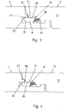
- FIG. 2 represents the lowering of the element 2 relative to the element 1 in the direction of arrow P.
- the spring element 11 slides with its underside 15 along the support surface 24 and remains due to the convex curvature during the joining operation with the support surface 24 in contact.
- the elastic material 18 is deformed in the rear free space 17 of the spring element 11.
- the spring element 11 is pivoted in the direction of the adjacent element 1.
- FIG. 3 shows the locked state of the elements 1, 2.
- the spring element 11 rests with its upper side 14 on an underside 23 adjacent to the locking edge 22 of the element 1.
- the spring element 11 is separated by the breakage of the predetermined breaking point 19 from the core 12 of the element 2. This is a brittle fracture.
- the predetermined breaking point 19 is configured so that the break at the transition from the in FIG. 2 position shown to the in FIG. 3 position shown.
- the spring element 11 is connected in the locking position only via the elastic material 18 with the core 12 of the element 2.
- the predetermined breaking point 19 adjacent undercut 20 is used to accommodate any breakage between core 12 and spring element 11 freed fragments.
- a downwardly facing contact surface 25 of the contact strip 21 abuts in the locking position on a horizontally oriented upper side 14 of the spring element 11, whereby an additional vertical support of the elements 1, 2 is achieved.
- the dome 5 is arranged almost completely behind the dome bulge 8 of the locking bar 3, so that a secure locking in the horizontal plane is ensured.
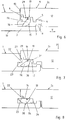
- FIG. 4 shows a cross section through a connecting region of two adjacent elements 1, 2a in an alternative embodiment of the second element 2a.
- no cutout is provided above the element 11a and the predetermined breaking point 19, so that in the illustrated locking position, the spring element 11a rests with its upper side 14 over a larger area than in the first embodiment on a downward facing, directly adjoining the predetermined breaking point 19 bearing surface 26.
- a further lowering of the second element 2a is not possible because the second element 2a is additionally supported on a bracket 27 of the first element 1.
- FIG. 5 shows a cross section through a connecting region of two adjacent elements 1, 2b before their locking.
- a predetermined breaking notch 28 is provided on the upper side 14 of the spring element 11 b in the region of the predetermined breaking point 19.
- This predetermined breaking notch 28 serves to selectively weaken the structure and, when connecting the elements 1, 2b to a break between the core 12 and spring element 11 b.
- the predetermined breaking notch 28 can absorb released material when it breaks.
- FIGS. 6 to 8 shown assembly positions of two adjacent elements and the reference numerals used correspond substantially to the illustrations of FIGS. 1 to 3 ,
- the spring element 11 c differs at the core of the element 2 c of the in the FIGS. 1 to 5 shown spring elements in that an elastic material 18 is arranged in a joint 29 on the head side 13 of the element 2 and not in a rear free space 17 of the spring element 11 c.
- the element 2c is arranged opposite to the element 1, that when lowering in the direction of arrow P analogous to FIG. 1 , the coupling bead 5 of the second element 2c engages a coupling channel 7 of the locking strip 3 and the coupling channel 4 of the second element 2c engages with the dome bead 8 of the locking strip 3 of the first element 1.
- this essentially serves for positional orientation in the horizontal laying plane V.
- the obliquely downwardly directed tongue of the spring element 11c also extends from a connection region of the spring element 11c with a core 12 of the element 2c to a head side 13 and an underside 10 of the second element 2c.
- An underside 15 of the spring element 11 c here also has a convex curvature, to which a planar area 30 adjoins. At this flat region 30 is followed by a substantially planar rear side 31 of the spring element 11c. Between the back 31 and the core 12 of the element 2 c, the free space 17 is arranged.
- the spring element 11 c is an integral part of the element 2 c, wherein a transition region from the core 12 of the element 2 c to the spring element 11 c is designed as a predetermined breaking point 19.
- FIG. 7 shows the lowering of the element 2c relative to the element 1 in the direction of arrow P.
- the spring element 11c slides with its underside 15 along the support surface 24 and remains due to the convex curvature during the joining operation with the support surface 24, as in FIG. 2 also shown, in contact.
- the elastic material 18 in the front-side joint 29 of the spring element 11 c is compressed or squeezed.
- the spring element 11 c is pivoted in the direction of the adjacent element 1 and the material in the region of the predetermined breaking point 19 to the breaking point and during further lowering beyond stretched.
- FIG. 8 shows the locked state of the elements 1, 2c.
- the spring element 11c abuts with its upper side 14 on an underside 23 next to the locking edge 22 of the element 1.
- the spring element 11c is separated by the breakage of the predetermined breaking point 19 from the core 12 of the element 2c.
- the flat portion 30 of the bottom 15 of the spring element 11 c is aligned in the locking position parallel to a support surface 24 of the element 1.
- the top 14 of the spring element 11 c is aligned parallel to the bottom 23 of the locking edge 22 and is applied to this.
Description
- Die Erfindung betrifft einen Belag aus mechanisch miteinander verbindbaren Elementen.
- Wand-, Decken- und Bodenbeläge, wie z.B. Fertigparkett, Holzböden oder Laminatfußböden, bestehen aus mehreren Reihen von in ihrer Konfiguration vorliegend rechteckigen Paneelen. Konventionell besitzen die Paneele auf einer Längsseite und auf einer Kopfseite durchgehende Nuten und auf der jeweils gegenüberliegenden Längsseite bzw. Kopfseite durchgehende Federn, die an die Nuten formschlüssig angepasst sind. Durch die Verbindung von Nut und Feder werden die Paneele verlegt, wobei die Paneele zweier benachbarter Reihen versetzt zueinander angeordnet werden.
- Es ist bekannt, an den Nuten und Federn mechanische Verriegelungsmittel auszubilden, welche bei in einem Fußbodenbelag benachbarten Paneelen miteinander in rastenden Eingriff gelangen. Hierdurch soll eine Fugenbildung im verlegten Fußbodenbelag durch Dehnungs- oder Schrumpfungsvorgänge vermieden werden. An die Nut und Feder der Paneele sind aneinander angepasste Verriegelungselemente in Form von Vertiefungen, Ausnehmungen oder Vorsprüngen ausgebildet, um verbundene Fußbodenpaneele in der zusammengefügten Lage leimlos zu halten. In der Regel werden die Paneele entlang ihrer Längsseiten ineinander gedreht oder geklickt und anschließend seitlich verschoben, so dass Verriegelungsleisten an den Kopfseiten in Eingriff gelangen. Um dieses zu erleichtern, können von der gegenüberliegenden Kopfseite her leichte Hammerschläge unter Zuhilfenahme eines Schlagklotzes angewandt werden. Hierbei besteht die Gefahr, dass es selbst bei sorgfältigstem Arbeiten zu Schäden an den Fußbodenpaneelen kommen kann.
- Es gibt auch Lösungen, bei denen die aneinander stoßenden Kopfseiten nicht durch Hammerschläge miteinander verriegelt werden müssen, sondern durch verschiebbare Federelemente. Ein Beispiel hierfür ist der in der
DE 20 2007 018 662 U1 beschriebene Bodenbelag, bei welchem identisch ausgebildete Paneele durch eine im Wesentlichen vertikale Fügebewegung in horizontaler und vertikaler Richtung miteinander verriegelt werden können, wobei die Verriegelung in vertikaler Richtung durch zumindest ein in horizontaler Richtung bewegbares, einstückig aus dem Kern an einer Seitenkante herausgebildetes Federelement bewirkbar ist, das bei der Fügebewegung hinter eine sich im Wesentlichen in horizontale Richtung erstreckende Verriegelungskante einschnappt. Das mindestens eine Federelement ist in Richtung der Oberseite und in Richtung der gegenüberliegenden Seitenkante gegenüber dem Kern frei und in seiner Seitenkante an mindestens einem der beiden Enden mit dem Kern verbunden. Es wird als nachteilig angesehen, dass das Federelement zum Verriegeln zunächst mit einer horizontal wirkenden Kraft beaufschlagt werden muss, um das Federelement zurückzudrücken, bevor sich die aufgebaute Federspannung entlädt und das Federelement hinter die Verriegelungsleiste schnappt. Ähnlich verhält es sich bei den in derEP 1 350 904 A2 beschriebenen Fußbodendielen, bei welchen die Feder, die an einer Stirnseite eines Fußbodenelements angebracht werden muss, zunächst zurückgedrückt werden muss, bevor sie in eine zur Verriegelung vorgegebene Aufnahme einschnappen kann. In jedem Fall muss ein hinreichend großer Freiraum hinter der Feder vorhanden sein, damit die Feder vor dem Einschnappen zurückgedrückt werden kann. - Aus der
EP 2 034 106 A1 ist ein Belag mit mechanisch verbindbaren Elementen in Form von Bodenpaneelen bekannt, die an ihren gegenüberliegenden Seiten eine korrespondierende Profilierung besitzen und über diese verriegelbar sind. Die Verriegelung wird durch ein elastisches Federelement bewirkt, welches an einem der Elemente durch eine formschlüssige Verbindung angelenkt ist und hinter eine sich in horizontale Richtung erstreckende Verriegelungskante des benachbarten Paneels verschwenkbar ist. Das Federelement wird in der Ausgangsstellung über einen Haftkleber als Sollbruchstelle mit dem Element verbunden. Die Sollbruchstelle versagt beim Verschwenken des Federelements. Die Herstellung einer formschlüssigen Verbindung zur Definition des Drehpunktes des Federelements ist relativ aufwändig. - Zum Stand der Technik ist ferner die
WO2004/003314 A1 zu nennen, die ein Fußbodensystem mit Paneelen betrifft, welche an ihren Seitenkanten miteinander verriegelbar sind. Die Verriegelung sieht ein einstückig an dem einen Paneel angeordnetes, vertikales Federelement vor, das auf seiner dem anderen Paneel abgewandten Seite eine Elastizitätsnut besitzt, die mit einem elastischen Mittel, wie z. B einem PVC-Kleber gefüllt ist. Das Federelement kann während der Verriegelung seitlich ausgelenkt werden und bleibt auch nach dem Verriegeln fest mit dem Paneel verbunden. Falls das Federelement abbrechen sollte, müsste es von dem elastischen Mittel in Position gehalten werden. Allerdings würde sich auf Grund der vertikalen Orientierung des Federelements zwangsläufig ein Höhenversatz zwischen den Paneelen einstellen. Der Erfindung liegt die Aufgabe zu Grunde, einen Belag aus mechanisch miteinander verbindbaren Elementen aufzuzeigen, welcher sich mit geringem Kraftaufwand sicher verriegeln lässt und welcher einfach herstellbar ist. - Der gegenständliche Teil dieser Aufgabe ist bei einem Belag mit den Merkmalen des Patentanspruchs 1 gelöst.
- Die Unteransprüche betreffen vorteilhafte Weiterbildungen der Erfindung.
- Der erfindungsgemäße Belag umfasst mechanisch miteinander verbindbare Elemente, wobei mindestens eines der Elemente ein Paneel ist. Die Erfindung beinhaltet die Möglichkeit, dass eines der Elemente als Paneel und das weitere Element als Rahmenbauteil für eine Rahmenkonstruktion beispielsweise für Doppelböden ausgeführt ist. Die nachfolgende Beschreibung der Erfindung bezieht sich auf eine Ausführung, bei welcher die zu verbindenden Elemente Paneele sind.
- Die Elemente besitzen an ihren gegenüberliegenden Seiten eine zueinander korrespondierende Profilierung, mittels welcher benachbarte Elemente durch eine im Wesentlichen vertikale oder schwenkende Fügebewegung in horizontaler Richtung und vertikaler Richtung miteinander verriegelbar sind. Bei den erfindungsgemäßen Elementen ist es möglich, das anzulegende Element abzuschwenken oder abzuklappen. Ebenso ist es möglich, die Elemente durch eine im Wesentlichen oder auch ausschließlich vertikale Bewegung miteinander zu verriegeln. Die gegenüberliegenden, mit einer korrespondierenden Profilierung im Sinne der vorliegenden Erfindung versehenen Seiten sind insbesondere Kopfseiten der Elemente. Die Profilierung kann prinzipiell an allen Seiten, also den Kopfseiten und den Längsseiten, der im Wesentlichen rechteckigen Elemente vorgesehen sein.
- Bei der Erfindung ist vorgesehen, dass die Verriegelung durch zumindest ein Federelement bewirkbar ist, das an einem der Elemente zum einen bereichsweise über einen elastischen Werkstoff mit einem Kern des Elements verbunden ist und zum anderen vor der Fügebewegung einstückiger Bestandteil des Elements ist. Der elastische Werkstoff ist in einen zwischen einer zum Kern des Elements gewandten Rückseite des Federelements und dem Kern angeordneten Freiraum eingebracht. Das derart angelenkte Federelement ist bei der Fügebewegung hinter eine sich im Wesentlichen in horizontaler Richtung erstreckende Verriegelungskante des benachbarten Elements verschwenkbar.
- Dadurch, dass sich die Verriegelungskante im Wesentlichen in horizontaler Richtung erstreckt, werden die beiden Elemente gegen Verlagerung in vertikaler Richtung, d.h. senkrecht zur Verlegeebene, gesichert. An den Elementen können zusätzliche Verriegelungsleisten vorgesehen sein, um zusätzlich zu der Verriegelung in vertikaler Richtung auch die Verriegelungen der Verlegeebene zu bewirken.
- Die einstückige Verbindung zwischen dem Federelement und dem Element ist als Sollbruchstelle konfiguriert, welche dafür vorgesehen ist, beim Verschwenken des Federelements zu versagen, insbesondere zu brechen. Beim Verschwenken bzw. Absenken des Federelements wird also durch die Sollbruchstelle bevorzugt ein gezielter Bruch zwischen dem Federelement und dem Kern des Elements bewirkt. Das Versagen bzw. der Bruch der Sollbruchstelle zwischen Federelement und Kern erfolgt vorzugsweise beim erstmaligen Verbinden zweier benachbarter Elemente.
- Die Sollbruchstelle ist so konfiguriert, dass bei Überschreiten einer bestimmten Belastung ein Versagen der Struktur genau an dieser Stelle erfolgt um die gewünschte Funktion, nämlich die Verlagerung des Federelements zu erreichen. Bei dem Versagen handelt es sich insbesondere um einen Sprödbruch. Das Versagen kann aber auch in einer Überdehnung des Kernmaterials, d. h. in einer bleibenden plastischen Verformung bestehen. Die Bruchmechanik ist abhängig von den Materialeigenschaften des Federelements, wobei das plastische Verformungsverhalten unter anderem vom Spannungszustand, der Temperatur, der Belastungsart und der Belastungsgeschwindigkeit abhängt. Nachfolgend wird zur Vereinfachung der Begriff brechen / Bruch für das Versagen der Sollbruchstelle verwendet und zwar unabhängig davon, ob es sich um eine plastische Verformung, um einen Teilbruch oder um einen kompletten Sprödbruch handelt.
- Beim Fügen der benachbarten Elemente gleitet das Federelement mit seiner Unterseite auf einer der Verriegelungskante gegenüberliegenden Stützfläche des benachbarten Elements. Hierbei ist das Federelement auf Grund einer materialspezifischen Elastizität des Elements, welche eine gewisse Verschwenkung des Federelements gegenüber seiner Ausgangsposition ermöglicht, ohne dass das Material plastisch verformt wird, also nachgibt oder bricht, noch einstückiger Bestandteil des Elements. Beim weiteren Absenken des Elements wird das Federelement weiter gegenüber seiner Ausgangsstellung verschwenkt. Das Federelement bricht im Bereich der Sollbruchstelle quasi vom Kern ab, bleibt aber gleichzeitig über den elastischen Werkstoff mit dem Kern des Elements verbunden. Optimalerweise erfolgt das Versagen der Sollbruchstelle, d. h. insbesondere der Bruch, sobald das Federelement in die horizontale Position zwischen einer Stützfläche und einer Unterseite der Verriegelungskante einrastet oder kurz vorher, d.h. relativ spät während des Fügens. Tritt ein Bruch vor dem Erreichen der Verriegelungsposition ein, fungiert die Bruchkante auf Seiten des Kerns als Widerlager, drückt auf die federelementseitige Bruchkante und bewirkt so, dass das Federelement die Verriegelungsposition erreicht. Dabei hält der elastische Werkstoff das Federelement so in Position, dass sich die Bruchkanten im Wesentlichen gegenüberstehen.
- Zusätzlich kann an der Sollbruchstelle eine Sollbruchkerbe vorgesehen sein zur gezielten Einleitung von Kerbspannungen und somit zur gezielten Positionierung der Bruchstelle. Gleichzeitig kann so auch der Verlauf der Bruchkanten zumindest teilweise beeinflusst werden. Zudem kann mit der Sollbruchkerbe der Zeitpunkt des Bruches, also wie weit das Federelement elastisch aus seiner Ausgangsposition heraus verschwenkt werden kann, bevor es zum Bruch kommt, festgelegt werden. Darüber hinaus kann beim Bruch frei werdendes Material von der Sollbruchkerbe aufgenommen werden.
- Ist keine Sollbruchkerbe vorgesehen, kann in einer vorteilhaften Ausgestaltung oberhalb der Sollbruchstelle, d.h. zur Oberseite des Elements hin, auch ein Freischnitt angeordnet sein. Dieser Freischnitt kann der Aufnahme beim Bruch zwischen Federelement und Kern eventuell entstehenden Materials dienen. Sowohl die Sollbruchkerbe als auch der Freischnitt oberhalb der Sollbruchstelle können gleichzeitig mit der Kontur des Federelements aus dem Kern geschnitten werden, ohne den Herstellungsaufwand nennenswert zu erhöhen.
- Die Stützfläche, mit welcher das Federelement korrespondiert, ist im Wesentlichen horizontal ausgerichtet und liegt der Verriegelungskante gegenüber. In einer vorteilhaften Ausgestaltung ist eine Unterseite der Verriegelungskante zur Stützfläche parallel. Die beim Fügen benachbarter Elemente auf der Stützfläche gleitende Unterseite des Federelements ist vorzugsweise konvex ausgestaltet. Dadurch steht das Federelement während des gesamten Fügens in Kontakt mit der Stützfläche und wird so durch die Stützfläche geführt. In vorteilhafter Weise ist eine Oberseite des Federelements vor der Fügebewegung schräg, d.h. von der Sollbruchstelle zur Stirnseite und Unterseite des Elements hin abfallend, ausgebildet. Bei der Herstellung der Elemente wird die schräg stehende Oberseite aus dem Kern freigeschnitten, nachdem der elastische Werkstoff in den rückseitigen Freiraum des Federelements eingebracht wurde.
- Nach dem Fügen liegt das Federelement in der Verriegelungsposition mit seiner Oberseite an einer Unterseite der Verriegelungskante in einer im Wesentlichen horizontalen Ausrichtung an.
- Vorzugsweise handelt es sich bei dem elastischen Werkstoff um einen Klebstoff, ein Elastomer, einen Reaktivklebstoff, einen Hot-Melt oder eine dauerelastische Dicht- oder Fugenmasse. Mit Reaktivklebstoff werden Klebstoffe bezeichnet, welche über chemische Reaktionen aushärten und abbinden. Zu diesen Dicht- oder Fugenmassen zählen auch Acrylate und Silicone. Die Auswahl des elastischen Werkstoffes erfolgt natürlich in Abhängigkeit der für die Elemente eingesetzen Werkstoffe, um eine gute Haftung zwischen dem elastischen Werkstoff und dem Element zu erhalten. Das erfindungsgemäß ausgestaltete Federelement muss zur Verriegelung zunächst keine Federkraft überwinden in dem Sinne, dass das Federelement von der benachbarten Seite des Elements zurückgedrückt wird. Es wird vielmehr ausschließlich in Richtung des benachbarten Elements verlagert. Das Federelement schnappt also nicht unter dem Einfluss einer Federkraft hinter die Verriegelungskante, sondern wird zwangsgeführt hinter die Verriegelungskante gedrängt. Das hat den Vorteil, dass kein übergroßer Freiraum auf der dem Kern des Elements zugewandten Rückseite des Federelements erforderlich ist, da das Federelement bei der Verriegelung nur in eine Richtung verlagert wird und durch die Verriegelungskante nicht in Richtung des Freiraums gedrückt wird. Die Verlagerung des Federelements erfolgt also ausschließlich in Richtung des benachbarten Elements.
- Nach dem Versagen, insbesondere dem Bruch der Sollbruchstelle ist das Federelement nur noch über den elastischen Werkstoff mit dem Kern verbunden. Die elastische Verbindung zwischen Federelement und Kern ist so konfiguriert, dass sie auch nach dem Fügen bestehen bleibt. Diese Verbindung ermöglicht gegebenenfalls trotz Bruchs ein nochmaliges Verlegen der Elemente. Darüber hinaus kann sich das Federelement nicht selbsttätig über die Rückstellkräfte des elastischen Werkstoffs wieder zurückbewegen, da es zwischen der Stützfläche und der Unterseite der Verriegelungskante gehalten wird. Vorzugsweise befindet sich das Federelement in einem Zustand der Selbsthemmung und kann nicht ohne eine fremde Kraft zurück in seine Ausgangsposition gelangen, so dass die Elemente sicher in der Verriegelungsposition, d.h. in der Verlegeebene, gehalten sind. Zusätzlich kann bevorzugt an einer Unterseite der Verriegelungskante und/oder einer Oberseite des Federelements eine die Reibung erhöhende Profilierung vorhanden sein.
- Es ist zwar theoretisch möglich, bei einem rein vertikalen Ablegen eines Elements nur ein einziges verschwenkbares, leistenartiges Federelement vorzusehen, es wird jedoch als zweckmäßig erachtet, wenn an einer Seite eines Elements mehrere unabhängig voneinander verschwenkbare Federelemente angeordnet sind. In diesem Fall ist nämlich nicht nur das im Wesentlichen vertikale Ablegen des Elements möglich, sondern auch das klemmungsfreie Abwinkeln oder Abklappen der Elemente, bei welchen beispielsweise im Kopfseitenbereich die Kopfseiten zunächst mit einer Ecke miteinander in Eingriff gelangen und dann durch weiteres Abklappen des anzulegenden Elements letztlich beide Kopfseiten parallel zueinander verlaufen und vollständig miteinander in Eingriff stehen.
- Da es bei einem einzigen langen Federelement zu einer ungleichmäßigen Belastung während des Abklappens kommen würde und damit zu Spannungen innerhalb des Federelements, ist es zweckmäßig, mehrere einzelne Federelemente vorzusehen, die zeitlich zueinander versetzt betätigt werden. Dabei können die Federelemente aneinander angrenzend oder voneinander beabstandet angeordnet sein. Vorteilhafterweise ist mehr als ein Federelement pro Seite angeordnet.
- Es ist auch denkbar, Federelemente unterschiedlicher Elastizitäten an einer Seite anzuordnen, wodurch ein gestufter Einrastvorgang ermöglicht wird. Die Federelemente können daher auch durchaus im Abstand zueinander angeordnet sein. Fertigungstechnisch ist es am einfachsten, wenn zunächst ein einziges entsprechend langes Federelement in einzelne Abschnitte unterteilt wird. Hierzu können mehrere Schlitze in dem ursprünglich einzigen Federelement ausgebildet werden, damit die so vereinzelten Federelemente beim Abklappen der Reihe nach betätigt werden können.
- Es besteht die Möglichkeit, einander benachbarte Federelemente zueinander relativ beweglich miteinander zu verbinden. Als Verbindungsmittel kann ein elastisches Bauelement dienen, wie z.B. ein elastischer Klebstoff, wie er auch in dem rückwärtigen Freiraum des Federelements zum Einsatz kommt. Die elastische Verbindung ermöglicht es, die Federelemente kleiner zu gestalten, ohne dass die Gefahr besteht, dass sich ein einzelnes Federelement von dem Element bei Beschädigung löst. Der Gestaltungsspielraum ist grundsätzlich größer, wenn die Federelemente zusätzlich klebetechnisch miteinander verbunden sind.
- In vorteilhafter Weiterbildung weist das die Verriegelungskante aufweisende Element eine unter das das Federelement tragende Element greifende Verriegelungsleiste auf. Diese Verriegelungsleiste ist dafür geeignet und vorgesehen, die benachbarten Elemente gegen Zugbelastungen in einer Verlegeebene zu sichern. Durch die zusätzliche Verriegelungsleiste werden ausschließlich horizontale Zugkräfte aufgenommen, also Zugbelastungen in der Verlegeebene. Dadurch wird sichergestellt, dass an der Oberseite kein Fügespalt verbleibt. Das Eintreten von Flüssigkeit und Verschmutzungen in etwaige Spalten wird verhindert.
- Die Verriegelungsleiste kann insbesondere bei Wandbelägen auch dazu dienen, an einer Unterkonstruktion, insbesondere einer wandseitigen Unterkonstruktion, befestigt zu werden. Zum Beispiel kann die Verriegelungsleiste durch ein Befestigungsmittel in Form eines Clips an der Unterkonstruktion befestigt werden. Denkbar ist auch, die Verriegelungsleiste unmittelbar anzuschrauben, anzunageln oder anzuheften, d.h. ohne zusätzlichen Clip zu fixieren.
- Der Erfindungsgedanke ist auf alle Bodensysteme und Wandsysteme anwendbar, bei denen ein Oberbelag auf einem Träger, bei welchem es sich insbesondere um eine Holzwerkstoffplatte, wie z.B. eine MDF- oder Spanplatte, handelt, angeordnet ist, wie beispielsweise Echtholzbeläge, Laminat, Träger mit lackierten Oberflächen als Oberbelag, Linoleum, Kork auf Trägerplatten etc. Bestehen die Elemente aus HDF- oder MDF-Material, ist eine Sollbruchkerbe zwar hilfreich, aber nicht unbedingt notwendig, da sich bei diesem Material ein klarer Faserbruch einstellt. Die Deckschicht kann insbesondere aus einem Dekorpapier mit Overlay bestehen, welches die Optik der Elemente bestimmt.
- Bei einem Fußbodenbelag kann es sich somit um einen Parkettboden, einen Fertigparkettboden, einen Echtholzboden oder um einen Laminatfußboden handeln. Ebenso eignen sich Elemente aus massiven Materialien wie beispielsweise Holzdielen, Holzelemente, gegossene Formplatten aus Plastik, Kunststoffen, Formteilen oder Gipsplatten.
- Der Erfindungsgedanke betrifft nicht nur das Verbinden von Elementen, sondern es ist, wie eingangs erwähnt, auch denkbar, ein Element als Rahmenbauteil für Rahmenböden oder Doppelböden auszuführen. Bei einer solchen Anwendung ist eines der zu verbindenden Elemente als Paneel und ein zweites Element als Rahmenbauteil konfiguriert. Das Paneel wird beim Zusammenbau in die aus einem oder mehreren Rahmenbauteilen bestehende Rahmenkonstruktion abgelegt und mit seinen Kopf- und/oder Längsseiten eingerastet.
- Die Erfindung wird nachfolgend anhand von in den schematischen Zeichnungen dargestellten Ausführungsbeispielen zur Verbindung zweier Elemente in Form von Paneelen näher erläutert. Natürlich sind die gezeigten Verbindungen ohne Weiteres auf die Verbindung zwischen einem Rahmenbauteil, einer Rahmenkonstruktion und einem Paneel übertragbar. Es zeigen:
- Figuren 1 bis 3
- jeweils einen Querschnitt durch den Verbindungsbereich zweier benachbarter Elemente in unterschiedlichen Montagestellungen, wobei
Figur 1 die noch unverriegelte Position zeigt und dieFigur 3 die Verriegelungsposition darstellt; - Figur 4
- einen Querschnitt durch den Verbindungsbereich zweier benachbarter Elemente in einer weiteren Ausführungsform;
- Figur 5
- einen Querschnitt durch den Verbindungsbereich zweier benachbarter Elemente in einer weiteren Ausführungsform und
- Figuren 6 bis 8
- jeweils einen Querschnitt durch den Verbindungsbereich zweier benachbarter Elemente in unterschiedlichen Montagestellungen.
-
Figur 1 zeigt einen Querschnitt durch zwei Elemente 1, 2 in Form von Paneelen. Es kann sich hierbei um einen kopfseitigen Querschnitt der Elemente 1, 2 handeln. Die Elemente 1, 2 sind identisch konfiguriert, so dass die Elemente 1, 2 zu einem Fußbodenbelag zusammengesetzt werden können. -
Figur 1 zeigt zwei benachbarte Elemente 1, 2 vor ihrer Verriegelung. Hierbei zeigt die Darstellung in der Bildebene links ein erstes Element 1 und in der Bildebene rechts ein zweites Element 2, welches dafür vorgesehen ist, mit dem ersten Element 1 verbunden zu werden. Das erste Element 1 weist eine Verriegelungsleiste 3 auf und das zweite Element 2 einen nach unten offenen Kuppelkanal 4 sowie einen sich hieran anschließenden, nach unten gerichteten endseitigen Kuppelwulst 5. Die Verriegelungsleiste 3 des ersten Elements 1 steht gegenüber einer Kopfseite 6 hervor. Das Element 2 wird so gegenüber dem Element 1 angeordnet, dass beim Absenken in Pfeilrichtung P der Kuppelwulst 5 des zweiten Paneels in einen Kuppelkanal 7 der Verriegelungsleiste 3 und der Kuppelkanal 4 des zweiten Elements 2 mit dem Kuppelwulst 8 der Verriegelungsleiste 3 des ersten Elements 1 in Eingriff gelangt. Dieser Bereich der Elemente 1, 2 dient im Wesentlichen zur Lageorientierung in horizontaler Ebene, wobei horizontal im Kontext der Erfindung der Verlegeebene V entspricht, die mit den zueinander parallelen Oberseiten 9 und Unterseiten 10 der Elemente 1, 2 zusammenfällt. - Wesentlicher Bestandteil der erfindungsgemäßen Profilierung ist ein Federelement 11. Das Federelement 11 ist eine in dieser Darstellung schräg nach unten gerichtete Zunge. Schräg bedeutet in diesem Fall ausgehend von einem Verbindungsbereich des Federelements 11 mit einem Kern 12 des Elements 2 zu einer Kopfseite 13 des zweiten Elements 2 und einer Unterseite 10 des zweiten Elements 2 verlaufend.
- Die Schrägstellung oder Neigung gegenüber der Verlegeebene V beträgt bei diesem Ausführungsbeispiel 53°. Sie liegt vorzugsweise zwischen 40° und 70°, insbesondere zwischen 50° und 60°. Im hier dargestellten Ausführungsbeispiel ist eine Oberseite 14 des Federelements 11 als ebene Fläche ausgestaltet. Eine Unterseite 15 des Federelements 11 weist eine konvexe Wölbung auf. An einer zum Kern 12 des Elements 2 weisenden Rückseite 16 des Federelements 11 schließt sich ein zur Unterseite 10 des Elements 2 geöffneter Freiraum 17 an. In diesem Freiraum 17 ist ein elastischer Werkstoff 18 angeordnet, welcher das Federelement 11 mit dem Kern 12 elastisch verbindet. Das Federelement 11 ist einstückiger Bestandteil des Elements 2, wobei ein Übergangsbereich vom Kern 12 des Elements 2 zum Federelement 11 als Sollbruchstelle 19 konfiguriert ist. Oberhalb der Sollbruchstelle 19 ist ein Freischnitt 20 angeordnet. Der Freischnitt 20 wird in Richtung zur Kopfseite 13 des Elements 2 durch eine zur Unterseite 10 des Elements 2 weisende Anlageleiste 21 begrenzt (
Figur 2 ). Der Freischnitt 20 oberhalb der Sollbruchstelle 19 ist in einem Schritt mit dem Ausschneiden der Oberseite 14 des Federelements 11 herstellbar. Vorteilhafterweise kann der Freischnitt 20 beim Versagen und insbesondere beim Bruch der Sollbruchstelle 19 frei werdendes Material aufnehmen. - Das Element 1 weist an seiner Kopfseite 6 eine parallel zur Verlegeebene V gegenüber der Kopfseite 6 hervorstehende Verriegelungskante 22 auf. Dabei verläuft eine sich an die Verriegelungskante 22 anschließende Unterseite 23 in dem hier dargestellten Ausführungsbeispiel parallel zu einer Stützfläche 24 der Verriegelungsleiste 3.
- In der in
Figur 1 dargestellten Ausgangsposition sind die Elemente 1, 2 mit ihren Kopfseiten 6, 13 zueinander ausgerichtet. Das Federelement 11 liegt mit einem ersten Bereich seiner konvexen Unterseite 15 auf der Stützfläche 24 der Verriegelungsleiste 3 auf. Es ist zu erkennen, dass das Federelement 11 ohne zu klemmen an der vorstehenden Verriegelungskante 22 vorbeigeführt werden kann. -
Figur 2 stellt das Absenken des Elements 2 gegenüber dem Element 1 in Richtung des Pfeils P dar. Hierbei gleitet das Federelement 11 mit seiner Unterseite 15 entlang der Stützfläche 24 und bleibt bedingt durch die konvexe Wölbung während des Fügevorgangs mit der Stützfläche 24 in Kontakt. Gleichzeitig wird der elastische Werkstoff 18 im rückseitigen Freiraum 17 des Federelements 11 verformt. Das Federelement 11 wird in Richtung des benachbarten Elements 1 verschwenkt. -
Figur 3 zeigt den verriegelten Zustand der Elemente 1, 2. Hierbei liegt das Federelement 11 mit seiner Oberseite 14 an einer Unterseite 23 neben der Verriegelungskante 22 des Elements 1 an. - Das Federelement 11 ist durch den Bruch der Sollbruchstelle 19 vom Kern 12 des Elements 2 getrennt. Hier handelt es sich um einen Sprödbruch. Die Sollbruchstelle 19 ist so konfiguriert, dass der Bruch beim Übergang von der in
Figur 2 dargestellten Position zu der inFigur 3 dargestellten Position erfolgt. Das Federelement 11 ist in der Verriegelungsposition nur noch über den elastischen Werkstoff 18 mit dem Kern 12 des Elements 2 verbunden. Der der Sollbruchstelle 19 benachbarte Freistich 20 dient zur Aufnahme eventuell beim Bruch zwischen Kern 12 und Federelement 11 frei werdender Bruchstücke. - Eine nach unten weisende Anlagefläche 25 der Anlageleiste 21 liegt in der Verriegelungsposition an einer horizontal ausgerichteten Oberseite 14 des Federelements 11 an, wodurch eine zusätzliche vertikale Abstützung der Elemente 1, 2 erzielt wird. Darüber hinaus ist in der Verriegelungsposition der Kuppelwulst 5 nahezu vollständig hinter dem Kuppelwulst 8 der Verriegelungsleiste 3 angeordnet, so dass auch eine sichere Arretierung in horizontaler Ebene gewährleistet ist.
-
Figur 4 zeigt einen Querschnitt durch einen Verbindungsbereich zweier benachbarter Elemente 1, 2a in einer alternativen Ausgestaltung des zweiten Elements 2a. Hierbei ist oberhalb des Elements 11a und der Sollbruchstelle 19 kein Freischnitt vorgesehen, so dass in der dargestellten Verriegelungsposition das Federelement 11a mit seiner Oberseite 14 großflächiger als beim ersten Ausführungsbeispiel an einer nach unten weisenden, sich direkt an die Sollbruchstelle 19 anschließenden Anlagefläche 26 anliegt. Ein weiteres Absenken des zweiten Elements 2a ist nicht möglich, da sich das zweite Element 2a zusätzlich an einer Konsole 27 des ersten Elements 1 abstützt. -
Figur 5 zeigt einen Querschnitt durch einen Verbindungsbereich zweier benachbarter Elemente 1, 2b vor ihrer Verriegelung. In dieser Ausführungsform ist an der Oberseite 14 des Federelements 11 b im Bereich der Sollbruchstelle 19 eine Sollbruchkerbe 28 vorgesehen. Diese Sollbruchkerbe 28 dient der gezielten Schwächung der Struktur und führt beim Verbinden der Elemente 1, 2b zu einem Bruch zwischen Kern 12 und Federelement 11 b. Darüber hinaus kann die Sollbruchkerbe 28 beim Bruch frei werdendes Material aufnehmen. - Die in den
Figuren 6 bis 8 dargestellten Montagestellungen zweier benachbarter Elemente sowie die verwendeten Bezugszeichen entsprechen im Wesentlichen den Darstellungen derFiguren 1 bis 3 . Allerdings unterscheidet sich das Federelement 11 c am Kern des Elements 2c von den in denFiguren 1 bis 5 dargestellten Federelementen dadurch, dass ein elastischer Werkstoff 18 in eine Fuge 29 an der Kopfseite 13 des Elements 2 angeordnet ist und nicht in einem rückseitigen Freiraum 17 des Federelements 11 c. - Zum Verbinden der benachbarten Elemente 1, 2c wird das Element 2c so gegenüber dem Element 1 angeordnet, dass beim Absenken in Pfeilrichtung P analog zu
Figur 1 , der Kuppelwulst 5 des zweiten Elements 2c an einen Kuppelkanal 7 der Verriegelungsleiste 3 und der Kuppelkanal 4 des zweiten Elements 2c mit dem Kuppelwulst 8 der Verriegelungsleiste 3 des ersten Elements 1 in Eingriff gelangt. Dies dient auch hier im Wesentlichen zur Lageorientierung in horizontaler Verlegeebene V. - Die analog zu den vorangehenden Darstellungen schräg nach unten gerichtete Zunge des Federelements 11 c verläuft ebenfalls von einem Verbindungsbereich des Federelements 11c mit einem Kern 12 des Elements 2c zu einer Kopfseite 13 und einer Unterseite 10 des zweiten Elements 2c. Eine Unterseite 15 des Federelements 11 c weist auch hier eine konvexe Wölbung auf, an welche sich ein eben ausgestalteter Bereich 30 anschließt. An diesen ebenen Bereich 30 schließt sich eine im Wesentlichen eben ausgestaltete Rückseite 31 des Federelements 11c an. Zwischen der Rückseite 31 und dem Kern 12 des Elements 2c ist der Freiraum 17 angeordnet. Das Federelement 11 c ist einstückiger Bestandteil des Elements 2c, wobei ein Übergangsbereich vom Kern 12 des Elements 2c zum Federelement 11 c als Sollbruchstelle 19 ausgeführt ist.
- Mit einem im Wesentlichen parallel zur Verlegeebene V verlaufenden Freischnitt wird im Verbindungsbereich zwischen Federelement 11c und dem Kern 12 des Elements 2c eine Fuge 29 erzeugt, in welcher ein elastischer Werkstoff 18 angeordnet ist. In der dargestellten Ausgangsposition in
Figur 6 liegt das Federelement 11 c mit einem ersten Bereich seiner konvexen Unterseite 15 auf der Stützfläche 24 der Verriegelungsleiste 3 auf und kann ohne zu klemmen an der vorstehenden Verriegelungskante 22 vorbeigeführt werden. -
Figur 7 zeigt das Absenken des Elements 2c gegenüber dem Element 1 in Richtung des Pfeils P. Dabei gleitet das Federelement 11c mit seiner Unterseite 15 entlang der Stützfläche 24 und bleibt bedingt durch die konvexe Wölbung während des Fügevorgangs mit der Stützfläche 24, wie inFigur 2 ebenfalls dargestellt, in Kontakt. Gleichzeitig wird der elastische Werkstoff 18 in der stirnseitigen Fuge 29 des Federelements 11 c gestaucht bzw. gequetscht. Das Federelement 11 c wird in Richtung des benachbarten Elements 1 verschwenkt und das Material im Bereich der Sollbruchstelle 19 bis zur Bruchgrenze und beim weiteren Absenken darüber hinaus gedehnt. -
Figur 8 zeigt den verriegelten Zustand der Elemente 1, 2c. Hierbei liegt das Federelement 11c mit seiner Oberseite 14 an einer Unterseite 23 neben der Verriegelungskante 22 des Elements 1 an. - Das Federelement 11c ist durch den Bruch der Sollbruchstelle 19 vom Kern 12 des Elements 2c getrennt. Der ebene Bereich 30 der Unterseite 15 des Federelements 11 c ist in der Verriegelungsposition parallel zu einer Stützfläche 24 des Elements 1 ausgerichtet. Die Oberseite 14 des Federelements 11 c ist parallel zur Unterseite 23 der Verriegelungskante 22 ausgerichtet und liegt an dieser an. Durch die Quetschung des elastischen Werkstoffs 18 in der Verriegelungsposition wirken die elastischen Rückstellkräfte auf den Kern 12 des Elements 2c und das Federelement 11c im Wesentlichen in Richtung der Verlegeebene V. Dadurch wird das Federelement 11c zusätzlich durch den Druck der Rückstellkräfte in seiner Verriegelungsposition gehalten.
-
- 1 -
- Element
- 2 -
- Element
- 2a -
- Element
- 2b -
- Element
- 2c -
- Element
- 3 -
- Verriegelungsleiste
- 4 -
- Kuppelkanal
- 5 -
- Kuppelwulst
- 6 -
- Kopfseite
- 7 -
- Kuppelkanal
- 8 -
- Kuppelwulst
- 9 -
- Oberseite
- 10 -
- Unterseite
- 11 -
- Federelement
- 11a -
- Federelement
- 11b -
- Federelement
- 11c -
- Federelement
- 12 -
- Kern
- 13 -
- Kopfseite
- 14 -
- Oberseite
- 15 -
- Unterseite
- 16 -
- Rückseite
- 17 -
- Freiraum
- 18 -
- Werkstoff
- 19 -
- Sollbruchstelle
- 20 -
- Freischnitt
- 21 -
- Anlageleiste
- 22 -
- Verriegelungskante
- 23 -
- Unterseite
- 24 -
- Stützfläche
- 25 -
- Anlagefläche
- 26 -
- Anlagefläche
- 27 -
- Konsole
- 28 -
- Sollbruchkerbe
- 29 -
- Fuge
- 30 -
- Bereich
- 31 -
- Rückseite
- P -
- Pfeil
- V -
- Verlegeebene
Claims (16)
- Belag aus mechanisch miteinander verbindbaren Elementen, wobei mindestens eines der Elemente (1, 2, 2a, 2b, 2c) ein Paneel ist, wobei die Elemente (1, 2, 2a, 2b, 2c) an ihren gegenüberliegenden Seiten eine korrespondierende Profilierung aufweisen und über diese Profilierung miteinander verriegelbar sind, wobei die Verriegelung durch wenigstens ein Federelement (11, 11a, 11b, 11c) bewirkt wird, welches an einem der Elemente (2, 2a, 2b, 2c) angelenkt ist und welches bei der Fügebewegung hinter eine sich im Wesentlichen in horizontale Richtung erstreckende Verriegelungskante (22) des benachbarten Elements (1) verschwenkbar ist, wobei das Federelement (11, 11 a, 11 b, 11 b) zum einen bereichsweise über einen elastischen Werkstoff (18) mit einem Kern (12) des Elements (2, 2a, 2b, 2c) verbunden ist und zum anderen vor der Fügebewegung einstückiger Bestandteil des Elements (2, 2a, 2b, 2c) ist, dadurch gekennzeichnet, dass die einstückige Verbindung zwischen dem Federelement (11, 11 a, 11 b, 11 c) und dem Element (2, 2a, 2b, 2c) als Sollbruchstelle (19) konfiguriert ist, welche dafür vorgesehen ist, beim Verschwenken des Federelements (11, 11a, 11b, 11c) zu versagen, insbesondere zu brechen; dass mittels der Profilierung ihrer Seiten benachbarte Elemente (1, 2, 2a, 2b, 2c) durch eine im Wesentlichen vertikale oder schwenkbare Fügebewegung in horizontaler und vertikaler Richtung miteinander verriegelbar sind; dass beim Fügen der benachbarten Elemente (1, 2, 2a, 2b, 2c) das Federelement (11, 11 a, 11 b, 11c) mit seiner Unterseite auf einer der Verriegelungskante (22) gegenüberliegenden Stützfläche (24) gleitet.
- Belag nach Anspruch 1, dadurch gekennzeichnet, dass die Verlagerung des Federelements (11, 11a, 11b, 11c) ausschließlich in Richtung des benachbarten Elements (1) erfolgt.
- Belag nach Anspruch 1 oder 2, dadurch gekennzeichnet, dass eine Oberseite (14) des Federelements (11, 11a, 11b, 11c) vor der Fügebewegung von der Sollbruchstelle (19) schräg zu einer Unterseite (10) und einer Kopfseite (13) des Elements (2, 2a, 2b, 2c) weist.
- Belag nach einem der Ansprüche 1 bis 3, dadurch gekennzeichnet, dass an einer Oberseite (14) des Federelements (11b) im Bereich der Sollbruchstelle (19) eine Sollbruchkerbe (28) angeordnet ist.
- Belag nach einem der Ansprüche 1 bis 4, dadurch gekennzeichnet, dass das Element (2, 2a, 2b, 2c) eine Oberseite (9) aufweist, wobei das Federelement (11, 11 a, 11 b, 11 c) nur an seinem der Oberseite (9) benachbarten Ende über die Sollbruchstelle (19) mit dem Element (2, 2a, 2b, 2c) verbunden ist.
- Belag nach einem der Ansprüche 1 bis 5, dadurch gekennzeichnet, dass zwischen einer Oberseite (9) des Elements (2) und der Sollbruchstelle (19) ein Freischnitt (20) angeordnet ist.
- Belag nach einem der Ansprüche 1 bis 6, dadurch gekennzeichnet, dass die Unterseite (15) des Federelements (11, 11a, 11b, 11c) konvex ausgestaltet ist.
- Belag nach einem der Ansprüche 1 bis 7, dadurch gekennzeichnet, dass eine im Wesentlichen ebene Oberseite (14) des Federelements (11, 11a, 11b, 11c) an einer Unterseite (23) der Verriegelungskante (22) in einer im Wesentlichen horizontalen Ausrichtung zur Anlage gelangt.
- Belag nach einem der Ansprüche 1 bis 8, dadurch gekennzeichnet, dass der elastische Werkstoff (18) in einem Freiraum (17) angeordnet ist, welcher sich zwischen einem Kern (12) des Elements (2, 2a, 2b) und einer dem Kern (12) zugewandten Rückseite (16) des Federelements (11, 11a, 11 b) befindet.
- Belag nach Anspruch 9, dadurch gekennzeichnet, dass der elastische Werkstoff (18) ein Klebstoff oder ein Reaktivklebstoff ist.
- Belag nach einem der Ansprüche 1 bis 10, dadurch gekennzeichnet, dass an einer Seite eines Elements mehrere unabhängig voneinander verschwenkbare Federelemente angeordnet sind.
- Belag nach einem der Ansprüche 1 bis 11, dadurch gekennzeichnet, dass benachbarte Federelemente durch ein elastisches Bauelement relativ zueinander beweglich miteinander verbunden sind.
- Belag nach einem der Ansprüche 1 bis 12, dadurch gekennzeichnet, dass das die Verriegelungskante (22) aufweisende Element (1) eine unter das das Federelement (11, 11 a, 11 b, 11 c) tragende Element (2, 2a, 2b, 2c) greifende Verriegelungsleiste (3) aufweist, welche geeignet ist, benachbarte Elemente (1, 2, 2a, 2b, 2c) gegen Zugebelastungen in einer Verlegeebene (V) zu sichern.
- Belag nach einem der Ansprüche 1 bis 13, dadurch gekennzeichnet, dass nach der Verriegelung zweier benachbarter Elemente (1, 2, 2a, 2b, 2c) die Oberseite (14) des Federelements (11, 11a, 11b, 11c) parallel zur Unterseite (23) der Verriegelungskante (22) und parallel zu einer Anlagefläche (25, 26) des das Federelement (11, 11a, 11 b, 11 c) tragenden Elements (2, 2a, 2b, 2c, 2d) ausgerichtet ist.
- Belag nach einem der Ansprüche 1 bis 14, dadurch gekennzeichnet, dass nach der Verriegelung zweier benachbarter Elemente (1, 2c) die Unterseite (15) des Federelements (11c) einen zur Stützfläche (24) parallel ausgerichteten Bereich (30) aufweist.
- Belag nach einem der Ansprüche 1 bis 15, dadurch gekennzeichnet, dass wenigstens ein Element als ein Rahmenbauteil für eine Rahmenkonstruktion ausgeführt ist.
Priority Applications (1)
| Application Number | Priority Date | Filing Date | Title |
|---|---|---|---|
| PL10779208T PL2483496T3 (pl) | 2009-10-02 | 2010-09-15 | Pokrycie z elementów łączonych ze sobą mechanicznie |
Applications Claiming Priority (2)
| Application Number | Priority Date | Filing Date | Title |
|---|---|---|---|
| DE102009048050A DE102009048050B3 (de) | 2009-10-02 | 2009-10-02 | Belag aus mechanischen miteinander verbindbaren Elementen |
| PCT/DE2010/001089 WO2011038709A1 (de) | 2009-10-02 | 2010-09-15 | Belag aus mechanischen miteinander verbindbaren elementen |
Publications (2)
| Publication Number | Publication Date |
|---|---|
| EP2483496A1 EP2483496A1 (de) | 2012-08-08 |
| EP2483496B1 true EP2483496B1 (de) | 2017-07-12 |
Family
ID=43382986
Family Applications (1)
| Application Number | Title | Priority Date | Filing Date |
|---|---|---|---|
| EP10779208.7A Active EP2483496B1 (de) | 2009-10-02 | 2010-09-15 | Belag aus mechanisch miteinander verbindbaren elementen |
Country Status (6)
| Country | Link |
|---|---|
| US (1) | US8752352B2 (de) |
| EP (1) | EP2483496B1 (de) |
| DE (1) | DE102009048050B3 (de) |
| PL (1) | PL2483496T3 (de) |
| RU (1) | RU2501923C1 (de) |
| WO (1) | WO2011038709A1 (de) |
Families Citing this family (56)
| Publication number | Priority date | Publication date | Assignee | Title |
|---|---|---|---|---|
| AU2009338857B2 (en) * | 2009-01-30 | 2016-03-10 | Valinge Innovation Ab | Mechanical lockings of floor panels and a tongue blank |
| DE102009034903B3 (de) * | 2009-07-27 | 2011-01-20 | Guido Schulte | Belag aus mechanisch miteinander verbindbaren Paneelen |
| EP2524093B1 (de) | 2010-01-12 | 2020-02-05 | Välinge Innovation AB | Mechanisches verschlusssystem für bodenplatten |
| EP3524754B1 (de) | 2010-01-14 | 2020-10-28 | Unilin, BV | Bodenplattenanordnung |
| BR112012018285B1 (pt) | 2010-02-04 | 2020-02-18 | Välinge Innovation AB | Conjunto de painéis de piso |
| DE102010012572B3 (de) * | 2010-03-23 | 2011-07-14 | Fritz Egger Gmbh & Co. Og | System von wenigstens zwei Paneelen |
| RU2525556C2 (ru) | 2010-04-15 | 2014-08-20 | Спанолюкс Н.В.-Див. Бальтерио | Блок напольных панелей |
| US8806832B2 (en) | 2011-03-18 | 2014-08-19 | Inotec Global Limited | Vertical joint system and associated surface covering system |
| UA109938C2 (uk) | 2011-05-06 | 2015-10-26 | Механічна фіксуюча система для будівельних панелей | |
| UA114715C2 (uk) | 2011-07-05 | 2017-07-25 | Сералок Інновейшн Аб | Механічна фіксація панелей настилу підлоги до язичка з нанесеним шаром клею |
| US9725912B2 (en) | 2011-07-11 | 2017-08-08 | Ceraloc Innovation Ab | Mechanical locking system for floor panels |
| US8650826B2 (en) | 2011-07-19 | 2014-02-18 | Valinge Flooring Technology Ab | Mechanical locking system for floor panels |
| US8763340B2 (en) | 2011-08-15 | 2014-07-01 | Valinge Flooring Technology Ab | Mechanical locking system for floor panels |
| US8769905B2 (en) | 2011-08-15 | 2014-07-08 | Valinge Flooring Technology Ab | Mechanical locking system for floor panels |
| US8857126B2 (en) | 2011-08-15 | 2014-10-14 | Valinge Flooring Technology Ab | Mechanical locking system for floor panels |
| US9216541B2 (en) | 2012-04-04 | 2015-12-22 | Valinge Innovation Ab | Method for producing a mechanical locking system for building panels |
| PL3235971T3 (pl) * | 2012-04-04 | 2019-03-29 | Välinge Innovation AB | Panel budowlany z mechanicznym systemem blokującym |
| US8596013B2 (en) | 2012-04-04 | 2013-12-03 | Valinge Innovation Ab | Building panel with a mechanical locking system |
| CA2867578C (en) * | 2012-04-04 | 2020-04-28 | Valinge Innovation Ab | Method for producing a mechanical locking system for building panels |
| DE102012107469A1 (de) | 2012-08-15 | 2014-02-20 | Guido Schulte | Belag aus mechanisch miteinander verbindbaren Elementen |
| EP3613920B1 (de) | 2012-11-22 | 2024-01-31 | Ceraloc Innovation AB | Mechanisches arretierungssystem für bodenplatten |
| DE102013100345B4 (de) | 2013-01-14 | 2023-07-06 | Guido Schulte | Belag aus mechanisch miteinander verbindbaren Elementen |
| US9194134B2 (en) | 2013-03-08 | 2015-11-24 | Valinge Innovation Ab | Building panels provided with a mechanical locking system |
| PL2978909T3 (pl) | 2013-03-25 | 2018-08-31 | Vaelinge Innovation Ab | Deski podłogowe z mechanicznym systemem blokującym |
| LT3014034T (lt) | 2013-06-27 | 2019-11-11 | Vaelinge Innovation Ab | Statybinė plokštė su mechaninio fiksavimo sistema |
| EA031216B1 (ru) | 2013-07-09 | 2018-12-28 | Сералок Инновейшн Аб | Комплект керамических или каменных плиток |
| DE102013112550A1 (de) * | 2013-08-07 | 2015-02-12 | Hamberger Industriewerke Gmbh | Verbindung für plattenförmige Bauelemente |
| EP3060728B1 (de) | 2013-10-25 | 2019-04-10 | Ceraloc Innovation AB | Mechanisches verschlusssystem für bodenplatten |
| DE102013113125A1 (de) | 2013-11-27 | 2015-05-28 | Guido Schulte | Fußboden-, Wand- oder Deckenpaneel und Verfahren zu dessen Herstellung |
| DE102013113109A1 (de) | 2013-11-27 | 2015-06-11 | Guido Schulte | Fußbodendiele |
| DE102013113130B4 (de) | 2013-11-27 | 2022-01-27 | Välinge Innovation AB | Verfahren zur Herstellung einer Fußbodendiele |
| HRP20220122T1 (hr) | 2014-01-10 | 2022-04-15 | Välinge Innovation AB | Postupak proizvodnje furniranog elementa |
| KR102398462B1 (ko) | 2014-03-24 | 2022-05-13 | 플로어링 인더스트리즈 리미티드 에스에이알엘 | 상호 로킹 가능한 패널의 세트 |
| US9260870B2 (en) | 2014-03-24 | 2016-02-16 | Ivc N.V. | Set of mutually lockable panels |
| RU2687440C2 (ru) | 2014-05-12 | 2019-05-13 | Велинге Инновейшн Аб | Способ изготовления элемента, покрытого шпоном, и такой элемент, покрытый шпоном |
| US9458634B2 (en) | 2014-05-14 | 2016-10-04 | Valinge Innovation Ab | Building panel with a mechanical locking system |
| US10246883B2 (en) | 2014-05-14 | 2019-04-02 | Valinge Innovation Ab | Building panel with a mechanical locking system |
| HRP20230136T1 (hr) | 2014-08-29 | 2023-03-31 | Välinge Innovation AB | Sustav vertikalnog spoja za površinsku ploču |
| DE102014112529A1 (de) * | 2014-09-01 | 2016-03-03 | Guido Schulte | Mechanische Verbindung für Paneele und Verfahren zur Montage einer Verriegelungsfeder in einem Paneel |
| US10138636B2 (en) | 2014-11-27 | 2018-11-27 | Valinge Innovation Ab | Mechanical locking system for floor panels |
| PL3237704T3 (pl) | 2014-12-22 | 2020-05-18 | Ceraloc Innovation Ab | Mechaniczny układ blokujący dla paneli podłogowych |
| CN107208426B (zh) | 2015-01-16 | 2019-07-26 | 塞拉洛克创新股份有限公司 | 用于地板镶板的机械锁定系统 |
| US11313123B2 (en) | 2015-06-16 | 2022-04-26 | Valinge Innovation Ab | Method of forming a building panel or surface element and such a building panel and surface element |
| EA035583B1 (ru) | 2015-12-17 | 2020-07-10 | Велинге Инновейшн Аб | Способ изготовления механической замковой системы для панелей |
| DE102016105463B4 (de) | 2016-03-23 | 2023-03-30 | Guido Schulte | Mechanische Verbindung für Paneele |
| BR112018071242B1 (pt) | 2016-04-25 | 2022-12-06 | Vãlinge Innovation Ab | Elemento folheado e método de produção de tal elemento folheado |
| EP3519650A4 (de) | 2016-09-30 | 2020-07-08 | Välinge Innovation AB | Durch vertikale verschiebung montierte und miteinander in der vertikalen und horizontalen richtung verriegelte plattenreihe |
| US10400458B1 (en) * | 2017-02-10 | 2019-09-03 | David W Moeller | Interlocking flooring system using locking strips |
| EP3737802B1 (de) | 2018-01-09 | 2023-05-10 | Välinge Innovation AB | Paneelsatz |
| CN111542432B (zh) | 2018-01-11 | 2023-01-10 | 瓦林格创新股份有限公司 | 饰面元件、用于生产饰面元件的方法 |
| PL3737559T3 (pl) | 2018-01-11 | 2024-01-22 | Välinge Innovation AB | Sposób wykonania elementu fornirowanego i element fornirowany |
| EP3807475B1 (de) | 2018-06-13 | 2023-11-15 | Ceraloc Innovation AB | Bodensystem mit einem verbindungssystem und einer zugehörigen verbindungsvorrichtung |
| WO2020145870A1 (en) | 2019-01-09 | 2020-07-16 | Välinge Innovation AB | A method to produce a veneer element and a veneer element |
| US11060302B2 (en) | 2019-01-10 | 2021-07-13 | Valinge Innovation Ab | Unlocking system for panels |
| WO2021059062A1 (en) * | 2019-09-23 | 2021-04-01 | Flooring Industries Limited, Sarl | Floor or wall covering |
| BR112022019195A2 (pt) | 2020-04-16 | 2022-11-01 | Vaelinge Innovation Ab | Método para produzir um elemento de construção, dispositivo de pressionamento e método de gravar em relevo uma superfície de madeira |
Family Cites Families (16)
| Publication number | Priority date | Publication date | Assignee | Title |
|---|---|---|---|---|
| DE20122778U1 (de) | 2001-08-10 | 2007-10-25 | Akzenta Paneele + Profile Gmbh | Paneel sowie Befestigungssystem für Paneele |
| DE50311595D1 (de) * | 2002-04-05 | 2009-07-30 | Tilo Gmbh | Fussbodendielen |
| DE10231921A1 (de) | 2002-06-28 | 2004-01-22 | E.F.P. Floor Products Fussböden GmbH | Paneel eines Fußbodensystems, insbesondere eines Laminatfußbodens |
| DE102004001363A1 (de) * | 2004-01-07 | 2005-08-04 | Hamberger Industriewerke Gmbh | Verbindung für Fußbodenelemente |
| SE529076C2 (sv) * | 2005-07-11 | 2007-04-24 | Pergo Europ Ab | En fog till paneler |
| DE202007017602U1 (de) | 2006-08-10 | 2008-04-03 | Schulte, Guido | Fußbodenbelag |
| DE102007015048B4 (de) * | 2007-03-26 | 2009-03-05 | Kronotec Ag | Paneel, insbesondere Bodenpaneel |
| US7726088B2 (en) * | 2007-07-20 | 2010-06-01 | Moritz Andre Muehlebach | Flooring system |
| US8220217B2 (en) * | 2007-07-20 | 2012-07-17 | Innovaris Ag | Flooring system |
| DE102007042250B4 (de) * | 2007-09-06 | 2010-04-22 | Flooring Technologies Ltd. | Einrichtung zur Verbindung und Verriegelung zweier Bauplatten, insbesondere Fussbodenpaneele |
| DE102007043308B4 (de) * | 2007-09-11 | 2009-12-03 | Flooring Technologies Ltd. | Einrichtung zur Verbindung und Verriegelung zweier Bauplatten, insbesondere Fussbodenpaneele |
| BE1018600A5 (nl) * | 2007-11-23 | 2011-04-05 | Flooring Ind Ltd Sarl | Vloerpaneel. |
| DE102008030281B3 (de) | 2008-06-30 | 2009-10-29 | Guido Schulte | Verfahren und Vorrichtung zum Einsetzen von Federn in eine Nut |
| PL2226447T3 (pl) * | 2009-02-27 | 2012-10-31 | Vaelinge Innovation Ab | Panel, zwłaszcza panel podłogowy |
| DE102009035275A1 (de) * | 2009-06-08 | 2010-12-09 | Fritz Egger Gmbh & Co. | Paneel eines Fußbodensystems |
| BE1018802A3 (nl) * | 2009-06-29 | 2011-09-06 | Flooring Ind Ltd Sarl | Paneel, meer speciaal vloerpaneel. |
-
2009
- 2009-10-02 DE DE102009048050A patent/DE102009048050B3/de active Active
-
2010
- 2010-09-15 WO PCT/DE2010/001089 patent/WO2011038709A1/de active Application Filing
- 2010-09-15 RU RU2012117221/03A patent/RU2501923C1/ru active
- 2010-09-15 US US13/499,804 patent/US8752352B2/en active Active
- 2010-09-15 PL PL10779208T patent/PL2483496T3/pl unknown
- 2010-09-15 EP EP10779208.7A patent/EP2483496B1/de active Active
Non-Patent Citations (1)
| Title |
|---|
| None * |
Also Published As
| Publication number | Publication date |
|---|---|
| DE102009048050B3 (de) | 2011-01-20 |
| RU2012117221A (ru) | 2013-11-10 |
| WO2011038709A1 (de) | 2011-04-07 |
| US20120192521A1 (en) | 2012-08-02 |
| EP2483496A1 (de) | 2012-08-08 |
| RU2501923C1 (ru) | 2013-12-20 |
| US8752352B2 (en) | 2014-06-17 |
| PL2483496T3 (pl) | 2017-12-29 |
Similar Documents
| Publication | Publication Date | Title |
|---|---|---|
| EP2483496B1 (de) | Belag aus mechanisch miteinander verbindbaren elementen | |
| DE102009041297B4 (de) | Belag aus mechanisch miteinander verbindbaren Elementen und ein Verfahren zur Herstellung von Elementen | |
| DE10206877B4 (de) | Paneel, insbesondere Fussbodenpaneel | |
| DE102007017087B4 (de) | Paneel, insbesondere Bodenpaneel | |
| DE102005010565C5 (de) | Leichtbauplatte und Verfahren zu ihrer Herstellung | |
| EP1527241B1 (de) | Vorrichtung zum verbinden von zwei plattenförmigen paneelen | |
| EP1294995B1 (de) | Fussbodensystem mit mehreren gleichen Fussbodenplatten | |
| EP2037128B1 (de) | Einrichtung zur Verbindung und Verriegelung zweier Bauplatten | |
| DE102008021970B4 (de) | Paneel mit vereinfachtem Rastelement | |
| DE102010012572B3 (de) | System von wenigstens zwei Paneelen | |
| EP1380710B1 (de) | Fussbodenpaneel und Verfahren zum Verlegen eines Fussbodens | |
| WO2011012104A2 (de) | Belag aus mechanisch miteinander verbindbaren paneelen | |
| DE60100600T2 (de) | Befestigungsvorrichtung für die längsränder von platten, latten oder wandverkleidungen mit kraftverteilung | |
| DE202010017748U1 (de) | Belag aus mechanisch miteinander verbindbaren Elementen | |
| DE102013100345B4 (de) | Belag aus mechanisch miteinander verbindbaren Elementen | |
| EP2795016B1 (de) | Paneel eines fussbodenbelags mit fremdelement | |
| WO2013023639A1 (de) | Belag aus mechanisch miteinander verbindbaren paneelen | |
| WO2016146112A1 (de) | Mechanische verbindung für paneele und verfahren zur herstellung von verbindungsmitteln | |
| DE10253236B4 (de) | Fussbodenpaneel und Verfahren zum Verlegen eines Fussbodenpaneels | |
| DE102016105463A1 (de) | Mechanische Verbindung für Paneele | |
| EP2885470A1 (de) | Belag aus mechanisch miteinander verbindbaren elementen | |
| EP3670783B1 (de) | Montageclip zur schwimmenden lagerung von wand- und deckenpaneelen | |
| DE102007046598B4 (de) | Paneel | |
| DE102010022290B4 (de) | Fußboden-, Wand- oder Deckenelement | |
| DE202005008917U1 (de) | Paneel, insbesondere Fußbodenpaneel |
Legal Events
| Date | Code | Title | Description |
|---|---|---|---|
| PUAI | Public reference made under article 153(3) epc to a published international application that has entered the european phase |
Free format text: ORIGINAL CODE: 0009012 |
|
| 17P | Request for examination filed |
Effective date: 20120228 |
|
| AK | Designated contracting states |
Kind code of ref document: A1 Designated state(s): AL AT BE BG CH CY CZ DE DK EE ES FI FR GB GR HR HU IE IS IT LI LT LU LV MC MK MT NL NO PL PT RO SE SI SK SM TR |
|
| DAX | Request for extension of the european patent (deleted) | ||
| GRAP | Despatch of communication of intention to grant a patent |
Free format text: ORIGINAL CODE: EPIDOSNIGR1 |
|
| INTG | Intention to grant announced |
Effective date: 20170316 |
|
| GRAS | Grant fee paid |
Free format text: ORIGINAL CODE: EPIDOSNIGR3 |
|
| GRAA | (expected) grant |
Free format text: ORIGINAL CODE: 0009210 |
|
| AK | Designated contracting states |
Kind code of ref document: B1 Designated state(s): AL AT BE BG CH CY CZ DE DK EE ES FI FR GB GR HR HU IE IS IT LI LT LU LV MC MK MT NL NO PL PT RO SE SI SK SM TR |
|
| REG | Reference to a national code |
Ref country code: GB Ref legal event code: FG4D Free format text: NOT ENGLISH |
|
| REG | Reference to a national code |
Ref country code: CH Ref legal event code: EP |
|
| REG | Reference to a national code |
Ref country code: AT Ref legal event code: REF Ref document number: 908487 Country of ref document: AT Kind code of ref document: T Effective date: 20170715 |
|
| REG | Reference to a national code |
Ref country code: IE Ref legal event code: FG4D Free format text: LANGUAGE OF EP DOCUMENT: GERMAN |
|
| REG | Reference to a national code |
Ref country code: DE Ref legal event code: R096 Ref document number: 502010013858 Country of ref document: DE |
|
| REG | Reference to a national code |
Ref country code: FR Ref legal event code: PLFP Year of fee payment: 8 |
|
| REG | Reference to a national code |
Ref country code: NL Ref legal event code: MP Effective date: 20170712 |
|
| REG | Reference to a national code |
Ref country code: LT Ref legal event code: MG4D |
|
| PG25 | Lapsed in a contracting state [announced via postgrant information from national office to epo] |
Ref country code: NO Free format text: LAPSE BECAUSE OF FAILURE TO SUBMIT A TRANSLATION OF THE DESCRIPTION OR TO PAY THE FEE WITHIN THE PRESCRIBED TIME-LIMIT Effective date: 20171012 Ref country code: HR Free format text: LAPSE BECAUSE OF FAILURE TO SUBMIT A TRANSLATION OF THE DESCRIPTION OR TO PAY THE FEE WITHIN THE PRESCRIBED TIME-LIMIT Effective date: 20170712 Ref country code: SE Free format text: LAPSE BECAUSE OF FAILURE TO SUBMIT A TRANSLATION OF THE DESCRIPTION OR TO PAY THE FEE WITHIN THE PRESCRIBED TIME-LIMIT Effective date: 20170712 Ref country code: NL Free format text: LAPSE BECAUSE OF FAILURE TO SUBMIT A TRANSLATION OF THE DESCRIPTION OR TO PAY THE FEE WITHIN THE PRESCRIBED TIME-LIMIT Effective date: 20170712 Ref country code: FI Free format text: LAPSE BECAUSE OF FAILURE TO SUBMIT A TRANSLATION OF THE DESCRIPTION OR TO PAY THE FEE WITHIN THE PRESCRIBED TIME-LIMIT Effective date: 20170712 Ref country code: LT Free format text: LAPSE BECAUSE OF FAILURE TO SUBMIT A TRANSLATION OF THE DESCRIPTION OR TO PAY THE FEE WITHIN THE PRESCRIBED TIME-LIMIT Effective date: 20170712 |
|
| PG25 | Lapsed in a contracting state [announced via postgrant information from national office to epo] |
Ref country code: ES Free format text: LAPSE BECAUSE OF FAILURE TO SUBMIT A TRANSLATION OF THE DESCRIPTION OR TO PAY THE FEE WITHIN THE PRESCRIBED TIME-LIMIT Effective date: 20170712 Ref country code: BG Free format text: LAPSE BECAUSE OF FAILURE TO SUBMIT A TRANSLATION OF THE DESCRIPTION OR TO PAY THE FEE WITHIN THE PRESCRIBED TIME-LIMIT Effective date: 20171012 Ref country code: IS Free format text: LAPSE BECAUSE OF FAILURE TO SUBMIT A TRANSLATION OF THE DESCRIPTION OR TO PAY THE FEE WITHIN THE PRESCRIBED TIME-LIMIT Effective date: 20171112 Ref country code: LV Free format text: LAPSE BECAUSE OF FAILURE TO SUBMIT A TRANSLATION OF THE DESCRIPTION OR TO PAY THE FEE WITHIN THE PRESCRIBED TIME-LIMIT Effective date: 20170712 Ref country code: GR Free format text: LAPSE BECAUSE OF FAILURE TO SUBMIT A TRANSLATION OF THE DESCRIPTION OR TO PAY THE FEE WITHIN THE PRESCRIBED TIME-LIMIT Effective date: 20171013 |
|
| REG | Reference to a national code |
Ref country code: DE Ref legal event code: R097 Ref document number: 502010013858 Country of ref document: DE |
|
| PG25 | Lapsed in a contracting state [announced via postgrant information from national office to epo] |
Ref country code: DK Free format text: LAPSE BECAUSE OF FAILURE TO SUBMIT A TRANSLATION OF THE DESCRIPTION OR TO PAY THE FEE WITHIN THE PRESCRIBED TIME-LIMIT Effective date: 20170712 Ref country code: CZ Free format text: LAPSE BECAUSE OF FAILURE TO SUBMIT A TRANSLATION OF THE DESCRIPTION OR TO PAY THE FEE WITHIN THE PRESCRIBED TIME-LIMIT Effective date: 20170712 Ref country code: RO Free format text: LAPSE BECAUSE OF FAILURE TO SUBMIT A TRANSLATION OF THE DESCRIPTION OR TO PAY THE FEE WITHIN THE PRESCRIBED TIME-LIMIT Effective date: 20170712 |
|
| REG | Reference to a national code |
Ref country code: CH Ref legal event code: PL |
|
| PLBE | No opposition filed within time limit |
Free format text: ORIGINAL CODE: 0009261 |
|
| STAA | Information on the status of an ep patent application or granted ep patent |
Free format text: STATUS: NO OPPOSITION FILED WITHIN TIME LIMIT |
|
| PG25 | Lapsed in a contracting state [announced via postgrant information from national office to epo] |
Ref country code: EE Free format text: LAPSE BECAUSE OF FAILURE TO SUBMIT A TRANSLATION OF THE DESCRIPTION OR TO PAY THE FEE WITHIN THE PRESCRIBED TIME-LIMIT Effective date: 20170712 Ref country code: MC Free format text: LAPSE BECAUSE OF FAILURE TO SUBMIT A TRANSLATION OF THE DESCRIPTION OR TO PAY THE FEE WITHIN THE PRESCRIBED TIME-LIMIT Effective date: 20170712 Ref country code: IT Free format text: LAPSE BECAUSE OF FAILURE TO SUBMIT A TRANSLATION OF THE DESCRIPTION OR TO PAY THE FEE WITHIN THE PRESCRIBED TIME-LIMIT Effective date: 20170712 Ref country code: SM Free format text: LAPSE BECAUSE OF FAILURE TO SUBMIT A TRANSLATION OF THE DESCRIPTION OR TO PAY THE FEE WITHIN THE PRESCRIBED TIME-LIMIT Effective date: 20170712 Ref country code: SK Free format text: LAPSE BECAUSE OF FAILURE TO SUBMIT A TRANSLATION OF THE DESCRIPTION OR TO PAY THE FEE WITHIN THE PRESCRIBED TIME-LIMIT Effective date: 20170712 |
|
| 26N | No opposition filed |
Effective date: 20180413 |
|
| REG | Reference to a national code |
Ref country code: IE Ref legal event code: MM4A |
|
| REG | Reference to a national code |
Ref country code: BE Ref legal event code: MM Effective date: 20170930 |
|
| PG25 | Lapsed in a contracting state [announced via postgrant information from national office to epo] |
Ref country code: LU Free format text: LAPSE BECAUSE OF NON-PAYMENT OF DUE FEES Effective date: 20170915 |
|
| PG25 | Lapsed in a contracting state [announced via postgrant information from national office to epo] |
Ref country code: CH Free format text: LAPSE BECAUSE OF NON-PAYMENT OF DUE FEES Effective date: 20170930 Ref country code: IE Free format text: LAPSE BECAUSE OF NON-PAYMENT OF DUE FEES Effective date: 20170915 Ref country code: LI Free format text: LAPSE BECAUSE OF NON-PAYMENT OF DUE FEES Effective date: 20170930 |
|
| PG25 | Lapsed in a contracting state [announced via postgrant information from national office to epo] |
Ref country code: BE Free format text: LAPSE BECAUSE OF NON-PAYMENT OF DUE FEES Effective date: 20170930 Ref country code: SI Free format text: LAPSE BECAUSE OF FAILURE TO SUBMIT A TRANSLATION OF THE DESCRIPTION OR TO PAY THE FEE WITHIN THE PRESCRIBED TIME-LIMIT Effective date: 20170712 |
|
| REG | Reference to a national code |
Ref country code: FR Ref legal event code: PLFP Year of fee payment: 9 |
|
| PG25 | Lapsed in a contracting state [announced via postgrant information from national office to epo] |
Ref country code: MT Free format text: LAPSE BECAUSE OF FAILURE TO SUBMIT A TRANSLATION OF THE DESCRIPTION OR TO PAY THE FEE WITHIN THE PRESCRIBED TIME-LIMIT Effective date: 20170712 |
|
| REG | Reference to a national code |
Ref country code: AT Ref legal event code: MM01 Ref document number: 908487 Country of ref document: AT Kind code of ref document: T Effective date: 20170915 |
|
| PG25 | Lapsed in a contracting state [announced via postgrant information from national office to epo] |
Ref country code: AT Free format text: LAPSE BECAUSE OF NON-PAYMENT OF DUE FEES Effective date: 20170915 |
|
| PG25 | Lapsed in a contracting state [announced via postgrant information from national office to epo] |
Ref country code: HU Free format text: LAPSE BECAUSE OF FAILURE TO SUBMIT A TRANSLATION OF THE DESCRIPTION OR TO PAY THE FEE WITHIN THE PRESCRIBED TIME-LIMIT; INVALID AB INITIO Effective date: 20100915 |
|
| PG25 | Lapsed in a contracting state [announced via postgrant information from national office to epo] |
Ref country code: CY Free format text: LAPSE BECAUSE OF NON-PAYMENT OF DUE FEES Effective date: 20170712 |
|
| PG25 | Lapsed in a contracting state [announced via postgrant information from national office to epo] |
Ref country code: MK Free format text: LAPSE BECAUSE OF FAILURE TO SUBMIT A TRANSLATION OF THE DESCRIPTION OR TO PAY THE FEE WITHIN THE PRESCRIBED TIME-LIMIT Effective date: 20170712 |
|
| PG25 | Lapsed in a contracting state [announced via postgrant information from national office to epo] |
Ref country code: TR Free format text: LAPSE BECAUSE OF FAILURE TO SUBMIT A TRANSLATION OF THE DESCRIPTION OR TO PAY THE FEE WITHIN THE PRESCRIBED TIME-LIMIT Effective date: 20170712 |
|
| PG25 | Lapsed in a contracting state [announced via postgrant information from national office to epo] |
Ref country code: PT Free format text: LAPSE BECAUSE OF FAILURE TO SUBMIT A TRANSLATION OF THE DESCRIPTION OR TO PAY THE FEE WITHIN THE PRESCRIBED TIME-LIMIT Effective date: 20170712 |
|
| PG25 | Lapsed in a contracting state [announced via postgrant information from national office to epo] |
Ref country code: AL Free format text: LAPSE BECAUSE OF FAILURE TO SUBMIT A TRANSLATION OF THE DESCRIPTION OR TO PAY THE FEE WITHIN THE PRESCRIBED TIME-LIMIT Effective date: 20170712 |
|
| PGFP | Annual fee paid to national office [announced via postgrant information from national office to epo] |
Ref country code: GB Payment date: 20230920 Year of fee payment: 14 |
|
| PGFP | Annual fee paid to national office [announced via postgrant information from national office to epo] |
Ref country code: PL Payment date: 20230908 Year of fee payment: 14 Ref country code: FR Payment date: 20230928 Year of fee payment: 14 Ref country code: DE Payment date: 20230928 Year of fee payment: 14 |