EP2476957A2 - Halteplatte für einen Gasbrenner und Gaskochfeld - Google Patents
Halteplatte für einen Gasbrenner und Gaskochfeld Download PDFInfo
- Publication number
- EP2476957A2 EP2476957A2 EP11196134A EP11196134A EP2476957A2 EP 2476957 A2 EP2476957 A2 EP 2476957A2 EP 11196134 A EP11196134 A EP 11196134A EP 11196134 A EP11196134 A EP 11196134A EP 2476957 A2 EP2476957 A2 EP 2476957A2
- Authority
- EP
- European Patent Office
- Prior art keywords
- hob
- gas
- plate
- holding plate
- outer edge
- Prior art date
- Legal status (The legal status is an assumption and is not a legal conclusion. Google has not performed a legal analysis and makes no representation as to the accuracy of the status listed.)
- Granted
Links
- 239000002241 glass-ceramic Substances 0.000 claims abstract description 15
- 239000011521 glass Substances 0.000 claims abstract description 7
- 239000002184 metal Substances 0.000 claims abstract description 6
- 229910052751 metal Inorganic materials 0.000 claims abstract description 6
- 239000000969 carrier Substances 0.000 claims description 16
- 230000002093 peripheral effect Effects 0.000 claims description 9
- 238000010411 cooking Methods 0.000 claims description 8
- 239000000463 material Substances 0.000 claims description 8
- 230000000284 resting effect Effects 0.000 claims description 4
- 238000007373 indentation Methods 0.000 claims description 3
- 210000001331 nose Anatomy 0.000 claims description 2
- 238000005580 one pot reaction Methods 0.000 claims description 2
- XEEYBQQBJWHFJM-UHFFFAOYSA-N Iron Chemical compound [Fe] XEEYBQQBJWHFJM-UHFFFAOYSA-N 0.000 description 2
- 238000004519 manufacturing process Methods 0.000 description 2
- 229910001220 stainless steel Inorganic materials 0.000 description 2
- 239000010935 stainless steel Substances 0.000 description 2
- 229910001018 Cast iron Inorganic materials 0.000 description 1
- 229910000831 Steel Inorganic materials 0.000 description 1
- 238000007792 addition Methods 0.000 description 1
- 238000005452 bending Methods 0.000 description 1
- 230000001419 dependent effect Effects 0.000 description 1
- 238000006073 displacement reaction Methods 0.000 description 1
- 230000003670 easy-to-clean Effects 0.000 description 1
- 238000004049 embossing Methods 0.000 description 1
- 230000002349 favourable effect Effects 0.000 description 1
- -1 for example Substances 0.000 description 1
- 238000009434 installation Methods 0.000 description 1
- 229910052742 iron Inorganic materials 0.000 description 1
- 239000010959 steel Substances 0.000 description 1
- 239000005341 toughened glass Substances 0.000 description 1
Images


Classifications
-
- F—MECHANICAL ENGINEERING; LIGHTING; HEATING; WEAPONS; BLASTING
- F24—HEATING; RANGES; VENTILATING
- F24C—DOMESTIC STOVES OR RANGES ; DETAILS OF DOMESTIC STOVES OR RANGES, OF GENERAL APPLICATION
- F24C3/00—Stoves or ranges for gaseous fuels
- F24C3/08—Arrangement or mounting of burners
- F24C3/085—Arrangement or mounting of burners on ranges
Definitions
- the present invention relates to a holding plate for a gas burner in a gas hob and a gas hob, in particular with a pot carrier arrangement.
- Gas hobs are produced, for example, as part of stoves or as integratable gas hobs in kitchen worktops.
- Several gas burners are arranged in the hob, which can be controlled via controls.
- pot carriers are provided. The pot carriers are usually connected to the gas hob and create a support surface for food containers.
- the distance of the support surface for food containers from the burner flame must be optimally adjusted so that an efficient heat transfer from the burner can be done on the food.
- a particular difficulty is also to create an aesthetically pleasing bearing surface over several burners in a gas hob with different burners.
- specially adapted to the gas burner pot carrier are used. This can lead to the case of a gas hob or a gas hob, several types of pot carriers are necessary. For reasons of production economy, however, it is better to have as few different modules as possible.
- an object of the present invention is to provide an improved way to create a flat pan support surface.
- the holding plate includes an opening for mounting the gas burner and a peripheral outer edge with a polygonal outline or a polygonal contour.
- the holding plate has a step from the outer edge in the direction of the opening.
- the holding plate allows on the one hand with its polygonal plan that pot carrier can be placed with a suitable frame form-fitting manner on the holding plate.
- the edge which may also be curved or curved, the installation position of a gas burner with respect to its height relative to the peripheral outer edge or a hob plate can be adjusted.
- the holding plate allows that even with different gas burners always the same type of pot carriers can be used.
- a misorientation of the pot carrier and retaining plate is practically excluded by the angular design, since a rotation or displacement is not possible.
- no additional pins for embossing or indentations for pan supports are necessary, so that a particularly easy to clean solution and an aesthetically pleasing overall impression of each hob is achieved.
- the outline is rectangular and in particular square.
- the step can be rounded or curved.
- the holding plate is made in one piece of material in one embodiment.
- materials for example, metal plates, but in principle also other materials in question.
- the retaining plate has a substantially smooth surface and no indentations or noses along its peripheral edge.
- the corners of the polygonal plan or outline may be rounded.
- the holding plate may be configured such that an area along the outer edge is formed for resting on a hob plate. In this respect, the holding plate can be inserted in or on an opening in a hob plate.
- the retaining plate is embodied as a heat shield in the manner of a polygonal disk for thermally shielding a hob plate.
- a heat shield it is prevented that, in particular, a cooking surface plate made of glass ceramic or hard glass is damaged by heat reflected from bottoms of food containers.
- a gas hob with a cooktop panel having at least one opening for a gas burner, and with at least one holding plate, which comprises an opening for mounting the gas burner and a peripheral outer edge with a polygonal outline.
- the holding plate has a step from the outer edge in the direction of the opening. The holding plate is in particular, as described above, executed.
- An area along the outer edge of the holding plate is preferably located on the hob plate.
- the opening of the holding plate extends below a hob plate surface. This ensures that, in particular, particularly powerful burners, such as Wokgas burners, can be arranged lower than other gas burners of the gas hob. At the same time, a uniform level of a bearing surface over the entire gas hob can be achieved by similar pot carriers. Due to the stepped design of the retaining plate, it is possible to always achieve the most favorable distance between flames and bearing surface of the pot carrier used.
- the gas hob has a plurality of openings for a plurality of gas burners and holding plates.
- the holding plates all have the same outline. This makes it possible that the same pot carrier can be used.
- the same comprises at least one pot carrier with a polygonal frame forming a base surface of the pot carrier, wherein the frame is placed in a form-fitting manner on a region of the peripheral outer edge of a holding plate.
- one or more pot carriers are placed as a Mehrfachtopfong on adjacent heat shields or holding plates.
- the respective pot carrier may have a frame which surrounds the gas burner and which has a section resting on the hob plate and a section resting on the heat shield.
- an edge of the pot carrier rotates around the angular contour of the heat shield or the holding plate and terminates flush.
- the pot carrier may each have inwardly directed fingers which form a support surface for a food container.
- a plurality of pot carriers each of which forms a bearing surface for a food container in the region of a gas burner, are provided, and the bearing surfaces are at the same distance from a cooking plate surface.
- the pot carriers are preferably the same.
- the hob plate is further at least partially made of hard glass or glass ceramic.
- hard glass or glass ceramic allow a particularly appealing aesthetic appearance of the gas hob.
- tempered glass or glass ceramic have little deformation with temperature changes during operation of the gas burners. It is therefore particularly easy to provide a level glass ceramic hob plate.
- the gas hob may also be formed with a cooktop panel in the manner of a cooktop tray, for example of molded material such as stainless steel. Cooker sinks, but also normal flat hobs can be used for example in a kitchen countertop or a cooker.
- the metal sheet is glued underneath with a hard glass or glass ceramic plate. The hard glass or glass ceramic plate then largely prevents deformation as a function of temperature changes of the metal sheet.
- FIG. 1 is a schematic cross-sectional view of an embodiment of a holding plate shown.
- the FIG. 2 shows a plan view of the holding plate.
- Retaining plate can be gas burners suitable in or attach to openings of hob plates.
- a hob plate 6 for example, made of glass ceramic.
- the hob plate 6 has an opening 15 into which a gas burner 3 is to be inserted.
- the gas burner 3 pierces the opening 15 upwards, so that above the glass ceramic plate 6 burner flames 9 can heat a cooking product container.
- Below the hob plate 6 fittings or leads to the gas burner 3 are provided below the hob plate 6 fittings or leads to the gas burner 3 are provided.
- a holding plate 1 with a square outline, as shown in the FIG. 2 is indicated.
- the holding plate 1 also has a central opening 2, on or in which the gas burner 3 is mounted.
- the holding plate 1 makes it possible, by its shape, in particular by a step 5, between the outer edge 4 and the opening 2, to set gas burner flames 9 in flexible height.
- the opening 2 is located lower than the hob plate 6.
- a distance of burner flame 9 can be optimally adjusted to a potential support surface 8 for Gargut electnisse.
- FIG. 1 further shows a pot carrier 7, which is positively placed on a portion 11 of the peripheral edge 4 of the holding plate 1.
- the pot carrier 7 has inwardly, ie in the direction of the burner 3, projecting fingers 10, the tops of which form a bearing surface 8 for Gargut electnisse.
- a distance 12 between the flame 9 and the support surface 8 can be adjusted depending on the gas burner 3 used. It is not necessary to change the nature of the pot carrier 7. In this respect, in the execution of the holding plate 1 as a polygonal disk with a level 5 in a corresponding gas hob identical pot carrier 7 can be used.
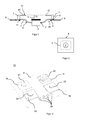
- FIG. 3 an embodiment of a gas hob with holding plates is shown in perspective.
- FIG. 4 shows a plan view of the embodiment of the gas hob.
- the Figures 3 and 4 show a built-in hob with a hob plate 6, for example, printed glass ceramic.
- There are four gas burners 21, 22, 23, 24 are provided which pierce both openings in the hob plate 6 as well as openings in the provided holding plates 16, 17, 18, 19.
- the gas burners 21, 22, 23, 24 are arranged in the quadrants of the rectangular hob plate 6. Furthermore, the holding plates 16, 17, 18, 19 all have the same floor plan.
- the provided in the upper right quadrant gas burner 22 is a wok burner with very high power. This burner 22 requires a distance between the burner flames and a support surface for Gargut proceedingsnisse such as pots or pans or a wok, which is different from the distances between gas flames of the burner 21, 23, 24 to the support surface. Therefore, the holding plate 17 is provided with a step, so that the gas burner 22, which is attached to the holding plate 17, is slightly lower. This ensures that, despite the different burner power or a different type of burner for all gas burners 21, 22, 23, 24 of the gas hob 13, the same pot carrier can be used.
- the holding plates which are designed as heat shields for the glass ceramic 6, each have a square frame 29, which forms their base.
- the frame 29 of the pot carrier 25, 26, 27, 28 is shaped such that it can be positively placed on the peripheral edges 4 of the heat shields 16, 17, 18, 19.
- the pot carriers are mounted in a non-rotating and slip-proof manner in the areas of the gas burners 21, 22, 23, 24. From the frame 29, fingers at 10 point inwards and form with their tops the bearing surface for pots and pans or the like.
- FIG. 6 shows a schematic cross-sectional view of the embodiment of the gas hob along a section axis AA.
- the front right gas burner 23 is shown.
- the Wokgasbrenner 22 On the right you can see the Wokgasbrenner 22.
- Both gas burners 22, 23 are fixed by means of a holding plate 17, 18, which are designed as a heat shield for the glass ceramic plate 6.
- the holding plate 18 is designed in the manner of a flat quadrangular disc.
- the holding plate or the heat shield 17 has in the direction of the gas burner 22, a step 5, the total offset the gas burner 22 in the downward direction.
- FIG. 7 is a further cross-sectional view along the section AA indicated.
- the heat shields or holding plates are shown hidden. It can be seen that the surface 30 of the hob plate 6 and the bearing surfaces 8 of the pot carriers 25 and 26 are equally spaced. Furthermore, it can be seen that the respective frame 29 of the pot carrier 25, 26 rests positively on the cooking surface plate surface 30. The frame 29 thus forms a pot carrier stand surface 31.
- FIG. 8 a perspective view of the gas hob 13 indicated.
- the pot carriers 28 and 29 (cf. FIG. 3 ) are removed.
- the support surfaces all have the same level or the same Distance with respect to the hob plate 6.
- the fact that the holding plate is used for example as a heat shield, and at the same time allows the correct distance of the gas burner flame to a pot carrier support surface or from the hob surface, same pot carrier can be used.
- a gas hob as indicated in the present figures, can be produced more cost-effectively than conventional gas hobs.
- the present invention has been described with reference to embodiments, it is variously modifiable.
- the said materials for the hob plate can be varied.
- the pot supports can have a wide variety of materials.
- the holding plates can also have other than square shapes.
- other numbers of gas burners in a gas hob are conceivable as shown.
Landscapes
- Engineering & Computer Science (AREA)
- Chemical & Material Sciences (AREA)
- Combustion & Propulsion (AREA)
- Mechanical Engineering (AREA)
- General Engineering & Computer Science (AREA)
- Cookers (AREA)
- Baking, Grill, Roasting (AREA)
- Gas Burners (AREA)
Abstract
Description
- Die vorliegende Erfindung betrifft eine Halteplatte für einen Gasbrenner in einem Gaskochfeld und ein Gaskochfeld, insbesondere mit einer Topfträgeranordnung.
- Gaskochfelder werden beispielsweise als Teil von Standherden oder auch als integrierbare Gaskochmulden in Küchenarbeitsplatten hergestellt. Dabei sind mehrere Gasbrenner in dem Kochfeld angeordnet, die über Bedienelemente angesteuert werden können. Um die Gargutbehälter, wie Pfannen oder Töpfe, in einem geeigneten Abstand von der Brennerflamme zu halten, werden Topfträger vorgesehen. Die Topfträger sind dabei meist mit der Gaskochmulde verbunden und schaffen eine Auflagefläche für Gargutbehälter.
- Insbesondere beim Einsatz unterschiedlicher Brennertypen in einem Gaskochfeld muss der Abstand der Auflagefläche für Gargutbehälter von der Brennerflamme jeweils optimal angepasst werden, damit ein effizienter Wärmeübertrag vom Brenner auf das Gargut erfolgen kann. Eine besondere Schwierigkeit besteht ferner darin, eine ästhetisch ansprechende Auflagefläche über mehrere Brenner hinweg bei einem Gaskochfeld mit verschiedenen Brennern zu schaffen. Üblicherweise werden daher speziell an die Gasbrenner angepasste Topfträger eingesetzt. Dies kann dazu führen, dass bei einer Gaskochmulde oder einem Gaskochfeld mehrere Typen von Topfträgern notwendig sind. Aus herstellungsökonomischen Gründen ist es jedoch günstiger, möglichst wenig unterschiedliche Baugruppen vorhalten zu müssen.
- Vor diesem Hintergrund besteht eine Aufgabe der vorliegenden Erfindung darin, eine verbesserte Möglichkeit anzugeben, eine ebene Topfträgerauflagefläche zu schaffen.
- Daher wird eine Halteplatte für einen Gasbrenner in einem Gaskochfeld vorgeschlagen. Die Halteplatte umfasst eine Öffnung zum Anbringen des Gasbrenners und eine umlaufende äußere Kante mit einem mehreckigen Umriss oder einer mehreckigen Kontur. Die Halteplatte hat dabei eine Stufe von der äußeren Kante in Richtung zu der Öffnung hin.
- Die Halteplatte ermöglicht einerseits mit ihrem mehreckigen Grundriss, dass Topfträger mit einem geeigneten Rahmen formschlüssig auf die Halteplatte aufgesetzt werden können. Andererseits kann durch die Kante, welche auch geschwungen oder gebogen sein kann, die Einbauposition eines Gasbrenners hinsichtlich seiner Höhe gegenüber der umlaufenden äußeren Kante oder einer Kochfeldplatte angepasst werden. Insofern ermöglicht die Halteplatte, dass selbst bei unterschiedlichen Gasbrennern immer derselbe Typ von Topf trägern verwendet werden kann.
- Eine Fehlorientierung von Topfträger und Halteplatte ist durch die eckige Ausführung praktisch ausgeschlossen, da eine Rotation oder Verschiebung nicht möglich ist. Gegenüber konventionellen Halterungen sind keine zusätzlichen Pins für Prägungen oder Einbuchtungen für Topfträger notwendig, so dass auch eine besonders reinigungsfreundliche Lösung und ein ästhetisch ansprechender Gesamteindruck des jeweiligen Kochfeldes erzielt wird.
- Vorzugsweise ist der Umriss rechteckig und insbesondere quadratisch ausgeführt. Die Stufe kann dabei abgerundet oder geschwungen ausgeführt sein.
- Die Halteplatte ist in einer Ausführungsform materialeinstückig gefertigt. Als Materialien kommen beispielsweise Metallplatten, prinzipiell jedoch auch andere Materialien in Frage.
- Vorzugsweise hat die Halteplatte eine im Wesentlichen glatte Oberfläche und keinerlei Einkerbungen oder Nasen entlang ihrer umlaufenden Kante. Die Ecken des mehreckigen Grundrisses bzw. Umrisses können abgerundet sein. Dabei kann die Halteplatte derart ausgestaltet sein, dass ein Bereich entlang der äußeren Kante zur Auflage auf einer Kochfeldplatte ausgebildet ist. Insofern lässt sich die Halteplatte in oder auf eine Öffnung in einer Kochfeldplatte einsetzen.
- In einer Ausführungsform ist die Halteplatte als ein Hitzeschild in der Art einer mehreckigen Scheibe zum thermischen Abschirmen einer Kochfeldplatte ausgeführt. In der Ausführung als Hitzeschild wird verhindert, dass insbesondere eine aus Glaskeramik oder Hartglas ausgeführte Kochfeldplatte durch von Böden von Gargutbehältnissen reflektierter Wärme beschädigt wird.
- Es wird ferner ein Gaskochfeld mit einer Kochfeldplatte vorgeschlagen, welche mindestens eine Öffnung für einen Gasbrenner aufweist, und mit mindestens einer Halteplatte, welche eine Öffnung zum Anbringen des Gasbrenners und eine umlaufende äußere Kante mit einem mehreckigen Umriss umfasst. Dabei weist die Halteplatte eine Stufe von der äußeren Kante in Richtung zu der Öffnung auf. Die Halteplatte ist insbesondere, wie zuvor beschrieben, ausgeführt.
- Ein Bereich entlang der äußeren Kante der Halteplatte liegt vorzugsweise auf der Kochfeldplatte auf. Bei einer Ausführungsform des Gaskochfeldes verläuft die Öffnung der Halteplatte unterhalb einer Kochfeldplattenoberfläche. Dadurch wird erreicht, dass insbesondere besonders leistungsstarke Brenner, wie beispielsweise Wokgasbrenner, gegenüber übrigen Gasbrennern des Gaskochfeldes niedriger angeordnet werden können. Gleichzeitig kann ein über das gesamte Gaskochfeld einheitliches Niveau einer Auflagefläche durch gleichartige Topfträger erzielt werden. Durch die stufige Ausführung der Halteplatte ist es möglich, immer den günstigsten Abstand zwischen Flammen und Auflagefläche der eingesetzten Topfträger zu erzielen.
- Vorzugsweise hat das Gaskochfeld daher mehrere Öffnungen für mehrere Gasbrenner und Halteplatten. Die Halteplatten haben dabei alle denselben Umriss. Dadurch wird ermöglicht, dass gleiche Topfträger eingesetzt werden können.
- In einer Weiterbildung des Gaskochfeldes umfasst dasselbe mindestens einen Topfträger mit einem eine Standfläche des Topfträgers ausbildenden mehreckigen Rahmen, wobei der Rahmen auf einen Bereich der umlaufenden äußeren Kante einer Halteplatte formschlüssig aufgesetzt ist.
- Es lässt sich somit eine besonders einfache Verbindung zwischen dem Topfträger und dem Hitzeschild erzielen. Es sind dabei keine Pins oder Verprägungen notwendig, um die Orientierung des Topfträgers auf dem Hitzeschild zu gewährleisten. Darüber hinaus sind bei der Herstellung nur gleichartige Topfträger vorzuhalten.
- Es ist möglich, dass einer oder mehrere Topfträger als Mehrfachtopfträger auf benachbarte Hitzeschilder oder Halteplatten aufgesetzt werden.
- Der jeweilige Topfträger kann insbesondere einen um den Gasbrenner umlaufenden Rahmen aufweisen, welcher einen auf der Kochfeldplatte aufliegenden Abschnitt und einen auf dem Hitzeschild aufliegenden Abschnitt aufweist. Insofern umläuft eine Kante des Topfträgers die eckige Kontur des Hitzeschildes oder der Halteplatte und schließt bündig ab.
- Der Topfträger kann jeweils nach innen gerichtete Finger aufweisen, die eine Auflagefläche für einen Gargutbehälter bilden.
- In einer bevorzugten Ausführungsform des Gaskochfeldes sind mehrere Topfträger, die jeweils eine Auflagefläche für einen Gargutbehälter im Bereich eines Gasbrenners bilden, vorgesehen, und die Auflageflächen haben denselben Abstand gegenüber einer Kochplattenoberfläche. Dabei sind vorzugsweise die Topfträger gleich.
- Vorzugsweise ist die Kochfeldplatte ferner zumindest teilweise aus Hartglas oder Glaskeramik gefertigt. Diese Materialien erlauben ein besonders ansprechendes ästhetisches Äußeres des Gaskochfeldes. Insbesondere haben Hartglas oder Glaskeramik nur geringe Verformung bei Temperaturveränderungen während des Betriebs der Gasbrenner. Es ist daher besonders einfach, eine Ebene Glaskeramikkochfeldplatte vorzusehen.
- Das Gaskochfeld kann auch mit einer Kochfeldplatte in der Art einer Kochmuldenwanne, beispielsweise aus geformtem Material wie Edelstahl ausgebildet sein. Kochmuldenwannen, aber auch normale flache Kochfelder können zum Beispiel in eine Küchenarbeitsplatte oder einen Standherd eingesetzt werden. Vorzugsweise ist dann das Metallblech unterseitig mit einer Hartglas- oder Glaskeramikplatte unterklebt. Die Hartglas- oder Glaskeramikplatte verhindert dann weitestgehend ein Verformen in Abhängigkeit von Temperaturveränderungen des Metallblechs.
- Weitere mögliche Implementierungen der Erfindung umfassen auch nicht explizit genannte Kombinationen von zuvor oder im Folgenden bezüglich der Ausführungsbeispiele beschriebenen Merkmalen. Dabei wird der Fachmann auch Einzelaspekte als Verbesserungen oder Ergänzungen zu der jeweiligen Grundform der Halteplatten oder des Gaskochfeldes hinzufügen.
- Weitere vorteilhafte Ausgestaltungen und Aspekte der Erfindung sind Gegenstand der Unteransprüche sowie der im Folgenden beschriebenen Ausführungsbeispiele der Erfindung. Im Weiteren wird die Erfindung anhand von bevorzugten Ausführungsformen unter Bezugnahme auf die beigelegten Figuren näher erläutert.
- Es zeigt dabei:
-
Fig. 1 : eine schematische Querschnittsansicht einer Ausführungsform einer Halteplatte; -
Fig. 2 : eine Darstellung der ersten Ausführungsform einer Halteplatte in der Draufsicht; -
Fig. 3 : eine perspektivische Darstellung einer Ausführungsform eines Gaskochfeldes mit Halteplatten; -
Fig. 4 : eine Darstellung der Ausführungsform eines Gaskochfeldes in der Draufsicht; -
Fig. 5 : eine Darstellung der Ausführungsform eines Gaskochfeldes mit einer Topfträgerbestückung in der Draufsicht; -
Fig. 6 : eine schematische Querschnittsansicht der Ausführungsform eines Gaskochfeldes mit Topfträgern; -
Fig. 7 : eine weitere Querschnittsansicht der Ausführungsform eines Gaskochfeldes mit Topfträgern; und -
Fig. 8 : eine perspektivische Darstellung der Ausführungsform eines Gaskochfeldes mit einer Topfträgerbestückung. - In den Figuren sind gleiche oder funktionsgleiche Elemente mit denselben Bezugszeichen versehen worden, sofern nichts anderes angegeben ist.
- In der
Figur 1 ist eine schematische Querschnittsansicht einer Ausführungsform einer Halteplatte dargestellt. DieFigur 2 zeigt eine Draufsicht der Halteplatte. Mittels der Halteplatte lassen sich Gasbrenner geeignet in oder an Öffnungen von Kochfeldplatten anbringen. - Daher ist in der
Figur 1 eine Kochfeldplatte 6, beispielsweise aus Glaskeramik dargestellt. Die Kochfeldplatte 6 hat eine Öffnung 15, in die ein Gasbrenner 3 eingesetzt werden soll. Der Gasbrenner 3 durchstößt die Öffnung 15 nach oben hin, so dass oberhalb der Glaskeramikplatte 6 Brennerflammen 9 einen Gargutbehälter erhitzen können. Unterhalb der Kochfeldplatte 6 sind Armaturen oder Zuleitungen zum Gasbrenner 3 vorgesehen. - Man erkennt eine Halteplatte 1 mit einem quadratischen Grundriss, wie es in der
Figur 2 angedeutet ist. Die Halteplatte 1 hat ebenfalls eine mittlere Öffnung 2, an oder in der der Gasbrenner 3 angebracht wird. Die Halteplatte 1 ermöglicht es, durch ihre Form, insbesondere durch eine Stufe 5, zwischen der äußeren Kante 4 und der Öffnung 2, Gasbrennerflammen 9 in flexibel in ihrer Höhe einzustellen. Bei der Darstellung derFigur 1 ist die Öffnung 2 tiefer gelegen als die Kochfeldplatte 6. Damit kann ein Abstand von Brennerflammen 9 zu einer potentiellen Auflagefläche 8 für Gargutbehältnisse optimal eingestellt werden. -
Figur 1 zeigt ferner einen Topfträger 7, der formschlüssig auf einen Bereich 11 der umlaufenden Kante 4 der Halteplatte 1 aufgesetzt ist. Der Topfträger 7 hat dabei nach innen, also in Richtung zum Brenner 3, ragende Finger 10, deren Oberseiten eine Auflagefläche 8 für Gargutbehältnisse bilden. Je nach Ausprägung des Knicks, der Biegung oder Stufe 5 der Halteplatte 1, kann in Abhängigkeit von dem verwendeten Gasbrenner 3 ein Abstand 12 zwischen der Flamme 9 und der Auflagefläche 8 eingestellt werden. Dabei ist es nicht nötig, die Art des Topfträgers 7 zu verändern. Insofern können bei der Ausführung der Halteplatte 1 als mehreckige Scheibe mit einer Stufe 5 bei einem entsprechenden Gaskochfeld identische Topfträger 7 verwendet werden. - In der
Figur 3 ist eine Ausführungsform eines Gaskochfeldes mit Halteplatten perspektivisch dargestellt. DieFigur 4 zeigt eine Draufsicht der Ausführungsform des Gaskochfeldes. DieFiguren 3 und4 zeigen ein Einbaukochfeld mit einer Kochfeldplatte 6, beispielsweise aus bedruckter Glaskeramik. Es sind vier Gasbrenner 21, 22, 23, 24 vorgesehen, die sowohl Öffnungen in der Kochfeldplatte 6 wie auch Öffnungen in den vorgesehenen Halteplatten 16, 17, 18, 19 durchstoßen. Es sind ferner Bedienelemente 20, wie Bedienknebel vorgesehen, mit denen sich die Leistung der verschiedenen Brenner 21-24 ansteuern lässt. - Man erkennt insbesondere in der
Figur 4 , dass die Gasbrenner 21, 22, 23, 24 in den Quadranten der rechteckigen Kochfeldplatte 6 angeordnet sind. Ferner haben die Halteplatten 16, 17, 18, 19 alle denselben Grundriss. Der in dem oberen rechten Quadranten vorgesehene Gasbrenner 22 ist ein Wokbrenner mit besonders hoher Leistung. Dieser Brenner 22 erfordert einen Abstand zwischen den Brennerflammen und einer Auflagefläche für Gargutbehältnisse wie Töpfe oder Pfannen oder einem Wok, der unterschiedlich ist von den Abständen zwischen Gasflammen der Brenner 21, 23, 24 zur Auflagefläche. Daher ist die Halteplatte 17 mit einer Stufe vorgesehen, so dass der Gasbrenner 22, welcher an der Halteplatte 17 befestigt wird, etwas tiefer liegt. Dadurch wird erreicht, dass trotz der unterschiedlichen Brennerleistung oder eines unterschiedlichen Brennertyps für alle Gasbrenner 21, 22, 23, 24 des Gaskochfeldes 13 dieselben Topfträger verwendet werden können. - Dies ist in der
Figur 5 in der Draufsicht dargestellt. Die Halteplatten, welche als Hitzeschutzschilde für die Glaskeramik 6 ausgeführt sind, haben jeweils einen viereckigen Rahmen 29, der deren Standfläche bildet. Der Rahmen 29 der Topfträger 25, 26, 27, 28 ist derart geformt, dass er formschlüssig auf die umlaufenden Kanten 4 der Hitzeschilder 16, 17, 18, 19 aufgesetzt werden kann. Dabei sind die Topfträger verdreh- und verrutschsicher in den Bereichen der Gasbrenner 21, 22, 23, 24 montiert. Von dem Rahmen 29 weisen Finger nach 10 nach innen und bilden mit ihren Oberseiten die Auflagefläche für Töpfe und Pfannen oder dergleichen aus. - Die
Figur 6 zeigt eine schematische Querschnittsansicht der Ausführungsform des Gaskochfeldes entlang einer Schnittachse A-A. In der Orientierung derFigur 6 ist links der vordere rechte Gasbrenner 23 dargestellt. Rechts erkennt man den Wokgasbrenner 22. Beide Gasbrenner 22, 23 sind mit Hilfe einer Halteplatte 17, 18, die als Hitzeschutzschild für die Glaskeramikplatte 6 ausgeführt sind, befestigt. Die Halteplatte 18 ist in der Art einer flachen viereckigen Scheibe ausgeführt. - Die Halteplatte bzw. der Hitzeschutzschild 17 hat jedoch in Richtung zu dem Gasbrenner 22 eine Stufe 5, die insgesamt den Gasbrenner 22 in Richtung nach unten versetzt.
- Dadurch wird der Abstand zwischen den Gasbrennerflammen und der Unterseite eines Gargutbehältnisses 14, wie eines Kochtopfes, optimal eingehalten.
- Man sieht in der
Figur 6 ferner, dass die Auflageflächen 8 der Topfträger 25, 26 dasselbe Niveau gegenüber der Glaskeramikkochfeldplatte 6 haben. Die beiden Topfträger 25, 26 sind auch gleich ausgeführt. - In der
Figur 7 ist eine weitere Querschnittsansicht entlang des Schnittes A-A angegeben. Die Hitzeschilder bzw. Halteplatten sind dabei verdeckt dargestellt. Man sieht, dass die Oberfläche 30 der Kochfeldplatte 6 und die Auflageflächen 8 der Topfträger 25 und 26 gleich beabstandet sind. Ferner erkennt man, dass der jeweilige Rahmen 29 der Topfträger 25, 26 formschlüssig auf der Kochfeldplattenoberfläche 30 aufliegt. Der Rahmen 29 bildet somit eine Topfträgerstandfläche 31 aus. - Schließlich ist in der
Figur 8 eine perspektivische Darstellung des Gaskochfeldes 13 angegeben. Dabei blickt man in der Orientierung derFiguren 4 und 5 seitlich von rechts auf das Gaskochfeld 13. Die Topfträger 28 und 29 (vgl.Figur 3 ) sind dabei entfernt. Die Ausführung der Halteplatten mit einer Stufe oder Biegung, welche ermöglicht, dass Gasbrenner in der Höhe versetzt zueinander in der Kochflächenebene angeordnet werden können, schafft ein besonders ansprechendes und gleichmäßiges Bild für das Gaskochfeld 13. Insbesondere die Auflageflächen haben alle dasselbe Niveau bzw. den gleichen Abstand bzgl. der Kochfeldplatte 6. Dadurch, dass die Halteplatte beispielsweise als Hitzeschutzschild eingesetzt ist, und gleichzeitig den korrekten Abstand der Gasbrennerflammen zu einer Topfträgerauflagefläche bzw. von der Kochfeldplattenoberfläche ermöglicht, können gleiche Topfträger verwendet werden. Insofern lässt sich ein Gaskochfeld, wie es in den vorliegenden Figuren angedeutet ist, aufwandsgünstiger herstellen als konventionelle Gaskochfelder. - Obwohl die vorliegende Erfindung anhand von Ausführungsbeispielen beschrieben wurde, ist sie vielfältig modifizierbar. Insbesondere die genannten Materialien für die Kochfeldplatte können variiert werden. Die Topfträger können unterschiedlichste Materialien aufweisen. Insbesondere ist es möglich, dieselben aus Gusseisen oder zumindest teilweise aus Edelstahl oder emailliertem Stahl zu fertigen. Die Halteplatten können auch andere als quadratische Formen haben. Selbstverständlich sind auch andere Anzahlen von Gasbrennern in einem Gaskochfeld denkbar als dargestellt ist.
-
- 1
- Halteplatte
- 2
- Halteplattenöffnung
- 3
- Gasbrenner
- 4
- umlaufende Halteplattenkante
- 5
- Stufe/Biegung
- 6
- Kochfeldplatte
- 7
- Topfträger
- 8
- Auflagefläche
- 9
- Flamme
- 10
- Finger
- 11
- Halteplattenbereich
- 12
- Flammenabstand
- 13
- Gaskochfeld
- 14
- Gargutbehälter
- 15
- Kochfeldplattenöffnung
- 16-19
- Hitzeschild
- 20
- Bedienelement
- 21-24
- Gasbrenner
- 25-28
- Topfträger
- 29
- Topfträgerrahmen
- 30
- Kochfeldplattenoberfläche
- 31
- Topfträgerstandfläche
Claims (15)
- Halteplatte (1) für einen Gasbrenner (3) in einem Gaskochfeld (13), wobei die Halteplatte (1) eine Öffnung (2) zum Anbringen des Gasbrenners (3) und eine umlaufende äußeren Kante (4) mit einem mehreckigen Umriss aufweist, wobei die Halteplatte (1) eine Stufe (5) von der äußeren Kante (4) in Richtung zu der Öffnung (2) aufweist.
- Halteplatte (1) nach Anspruch 1, dadurch gekennzeichnet, dass der Umriss rechteckig, insbesondere quadratisch, ist.
- Halteplatte (1) nach Anspruch 1 oder 2, dadurch gekennzeichnet, dass die Stufe abgerundet oder geschwungen ausgeführt ist.
- Halteplatte (1) nach einem der Ansprüche 1 - 3, dadurch gekennzeichnet, dass die Halteplatte (1) materialeinstückig gefertigt ist.
- Halteplatte (1) nach einem der Ansprüche 1 - 4, dadurch gekennzeichnet, dass die Halteplatte (1) eine glatte Oberfläche aufweist und keine Einkerbungen oder Nasen entlang ihrer umlaufenden Kanten aufweist.
- Halteplatte (1) nach einem der Ansprüche 1 - 5, dadurch gekennzeichnet, dass die Halteplatte (1) abgerundete Ecken hat.
- Halteplatte (1) nach einem der Ansprüche 1 - 6, dadurch gekennzeichnet, dass ein Bereich (11) entlang der äußeren Kante zur Auflage auf einer Kochfeldplatte (6) ausgebildet ist.
- Halteplatte (1) nach einem der Ansprüche 1 - 7, dadurch gekennzeichnet, dass die Halteplatte (1) als Hitzeschild in der Art einer mehreckigen Scheibe zum thermischen Abschirmen einer Kochfeldplatte (6) ausgeführt ist.
- Gaskochfeld (13) mit einer Kochfeldplatte (6), welche mindestens eine Öffnung (15) für einen Gasbrenner (3) aufweist, und mit mindestens einer Halteplatte (1) nach einem der Ansprüche 1-8, wobei ein Bereich (11) entlang der äußeren Kante (4) der Halteplatte (1) auf der Kochfeldplatte (6) aufliegt.
- Gaskochfeld (13) nach Anspruch 9, dadurch gekennzeichnet, dass die Öffnung (2) der Halteplatte (1) unterhalb einer Kochfeldplattenoberfläche (30) verläuft.
- Gaskochfeld (13) nach Anspruch 9 oder 10, dadurch gekennzeichnet, dass das Gaskochfeld (13) mehrere Öffnungen (15) für Gasbrenner (21 - 24) und Halteplatten (16 - 19) umfasst, wobei alle Halteplatten (16 - 19) denselben Umriss haben.
- Gaskochfeld (13) nach einem der Ansprüche 9-11, ferner umfassend mindestens einen Topfträger (25 - 28) mit einem eine Standfläche (31) des Topfträgers (25 - 28) ausbildenden mehreckigen Rahmen (29), welcher auf einen Bereich der umlaufenden äußeren Kante (4) einer Halteplatte (16 - 19) formschlüssig aufgesetzt ist.
- Gaskochfeld (13) nach Anspruch 11 und 12, dadurch gekennzeichnet, dass mehrere Topfträger (25 - 28) jeweils eine Auflagefläche (25) für einen Gargutbehälter (14) im Bereich eines Gasbrenners (21 - 24) bilden, und die Auflageflächen (25) denselben Abstand gegenüber einer Kochplattenoberfläche (30) haben. (wobei Topfträger gleich sind)
- Gaskochfeld (13) nach einem der Ansprüche 9-11, dadurch gekennzeichnet, dass die Kochfeldplatte (6) zumindest teilweise aus Hartglas oder Glaskeramik gefertigt ist.
- Gaskochfeld nach einem der Ansprüche 9-11, dadurch gekennzeichnet, dass die Kochfeldplatte (6) zumindest teilweise aus einem Metallblech in der Art einer Mulde und einer mit einer auf das Metallblech unterseitig geklebten Hartglas- oder Glaskeramikplatte gefertigt ist.
Priority Applications (1)
| Application Number | Priority Date | Filing Date | Title |
|---|---|---|---|
| EP11196134.8A EP2476957B1 (de) | 2011-01-17 | 2011-12-30 | Gaskochfeld |
Applications Claiming Priority (3)
| Application Number | Priority Date | Filing Date | Title |
|---|---|---|---|
| EP11382008 | 2011-01-17 | ||
| ES201130307 | 2011-03-07 | ||
| EP11196134.8A EP2476957B1 (de) | 2011-01-17 | 2011-12-30 | Gaskochfeld |
Publications (3)
| Publication Number | Publication Date |
|---|---|
| EP2476957A2 true EP2476957A2 (de) | 2012-07-18 |
| EP2476957A3 EP2476957A3 (de) | 2015-11-18 |
| EP2476957B1 EP2476957B1 (de) | 2017-10-18 |
Family
ID=45581720
Family Applications (1)
| Application Number | Title | Priority Date | Filing Date |
|---|---|---|---|
| EP11196134.8A Active EP2476957B1 (de) | 2011-01-17 | 2011-12-30 | Gaskochfeld |
Country Status (2)
| Country | Link |
|---|---|
| EP (1) | EP2476957B1 (de) |
| ES (1) | ES2645721T3 (de) |
Cited By (3)
| Publication number | Priority date | Publication date | Assignee | Title |
|---|---|---|---|---|
| CN112856489A (zh) * | 2021-01-07 | 2021-05-28 | 宁波方太厨具有限公司 | 一种用于燃气灶的集热罩及具有该集热罩的燃气灶 |
| CN115003961A (zh) * | 2020-02-07 | 2022-09-02 | Bsh家用电器有限公司 | 带有热保护器的燃气灶具 |
| EP3948093A4 (de) * | 2019-04-05 | 2022-11-02 | Mamur Teknoloji Sistemleri San. A.S. | Modulares kochfeld mit einem wok-modul |
Family Cites Families (6)
| Publication number | Priority date | Publication date | Assignee | Title |
|---|---|---|---|---|
| US2429279A (en) * | 1945-04-09 | 1947-10-21 | Kalamazoo Stove & Furnace Comp | Top structure for cooking stoves or ranges |
| US5345062A (en) * | 1992-10-26 | 1994-09-06 | Inge Maudal | Apparatus for supporting Asian WOKS on modern kitchen ranges |
| US6173708B1 (en) * | 1999-11-15 | 2001-01-16 | Maytag Corporation | Gas burner mounting assembly for appliance with ceramic based cooktop |
| DE102005046589A1 (de) * | 2005-09-28 | 2007-03-29 | BSH Bosch und Siemens Hausgeräte GmbH | Anordnung eines Topfträgers |
| DE102007043259A1 (de) * | 2007-09-11 | 2009-03-12 | BSH Bosch und Siemens Hausgeräte GmbH | Gaskochfeld |
| US7881593B2 (en) * | 2007-11-16 | 2011-02-01 | Cfom Inc. | Gas cooking appliance with removable burners and useable work area |
-
2011
- 2011-12-30 ES ES11196134.8T patent/ES2645721T3/es active Active
- 2011-12-30 EP EP11196134.8A patent/EP2476957B1/de active Active
Non-Patent Citations (1)
| Title |
|---|
| None |
Cited By (3)
| Publication number | Priority date | Publication date | Assignee | Title |
|---|---|---|---|---|
| EP3948093A4 (de) * | 2019-04-05 | 2022-11-02 | Mamur Teknoloji Sistemleri San. A.S. | Modulares kochfeld mit einem wok-modul |
| CN115003961A (zh) * | 2020-02-07 | 2022-09-02 | Bsh家用电器有限公司 | 带有热保护器的燃气灶具 |
| CN112856489A (zh) * | 2021-01-07 | 2021-05-28 | 宁波方太厨具有限公司 | 一种用于燃气灶的集热罩及具有该集热罩的燃气灶 |
Also Published As
| Publication number | Publication date |
|---|---|
| EP2476957A3 (de) | 2015-11-18 |
| ES2645721T3 (es) | 2017-12-07 |
| EP2476957B1 (de) | 2017-10-18 |
Similar Documents
| Publication | Publication Date | Title |
|---|---|---|
| EP2476958A2 (de) | Topfträgeranordnung für ein Gaskochfeld und Gaskochfeld | |
| DE69821168T2 (de) | Kochmulde | |
| EP2556304B1 (de) | Topfträger und gaskochstelle | |
| EP2476957B1 (de) | Gaskochfeld | |
| DE102005027198A1 (de) | Zusatztopfträger für Gaskochfelder | |
| DE19861078C2 (de) | Gaskochgerät | |
| EP1693621A1 (de) | Gaskochmulde | |
| WO2013150004A1 (de) | Topfträger und gaskochfeld | |
| EP2226566A2 (de) | Backherd mit pyrolytischem Reinigungssystem sowie Backblech-Halteelement für diesen Herd | |
| EP2564121B1 (de) | Gaskochfeld mit hitzeschild | |
| EP1673579B1 (de) | Gaskochfeld | |
| EP3029383B1 (de) | Dunstabzugshaube | |
| DE60025033T2 (de) | Kochplatte | |
| DE102008016628A1 (de) | Gaskochfeld | |
| DE102012208571A1 (de) | Kochfeldanordnung | |
| EP2159490B1 (de) | Topfträger für ein Gaskochfeld | |
| EP2476959A2 (de) | Verfahren zum Herstellen einer Serie von Gaskochfeldern und Gaskochfeldanordnung | |
| WO2007033943A1 (de) | Hocheinbau-gargerät | |
| WO2014082756A2 (de) | Kochstelle eines gasherdes | |
| DE102020113079B4 (de) | Aufsatz-Platte, vorzugsweise Teppanyaki-Platte, für ein Kochfeld | |
| DE60300940T2 (de) | Konstruktive einrichtung für kochgeräte | |
| DE102010028505A1 (de) | Flächentopfträger und Gaskochfläche | |
| DE102010028507A1 (de) | Kochmulde | |
| EP2783163B1 (de) | Zierrahmen für ein haushaltsgerät, haushaltsgerät mit einem derartigen zierrahmen und verfahren zum herstellen eines zierrahmens | |
| EP2756232B1 (de) | Kochfeldanordnung |
Legal Events
| Date | Code | Title | Description |
|---|---|---|---|
| PUAI | Public reference made under article 153(3) epc to a published international application that has entered the european phase |
Free format text: ORIGINAL CODE: 0009012 |
|
| AK | Designated contracting states |
Kind code of ref document: A2 Designated state(s): AL AT BE BG CH CY CZ DE DK EE ES FI FR GB GR HR HU IE IS IT LI LT LU LV MC MK MT NL NO PL PT RO RS SE SI SK SM TR |
|
| AX | Request for extension of the european patent |
Extension state: BA ME |
|
| RAP1 | Party data changed (applicant data changed or rights of an application transferred) |
Owner name: BSH HAUSGERAETE GMBH |
|
| PUAL | Search report despatched |
Free format text: ORIGINAL CODE: 0009013 |
|
| AK | Designated contracting states |
Kind code of ref document: A3 Designated state(s): AL AT BE BG CH CY CZ DE DK EE ES FI FR GB GR HR HU IE IS IT LI LT LU LV MC MK MT NL NO PL PT RO RS SE SI SK SM TR |
|
| AX | Request for extension of the european patent |
Extension state: BA ME |
|
| RIC1 | Information provided on ipc code assigned before grant |
Ipc: F24C 15/10 20060101ALI20151009BHEP Ipc: F24C 3/08 20060101AFI20151009BHEP |
|
| 17P | Request for examination filed |
Effective date: 20160518 |
|
| RBV | Designated contracting states (corrected) |
Designated state(s): AL AT BE BG CH CY CZ DE DK EE ES FI FR GB GR HR HU IE IS IT LI LT LU LV MC MK MT NL NO PL PT RO RS SE SI SK SM TR |
|
| GRAP | Despatch of communication of intention to grant a patent |
Free format text: ORIGINAL CODE: EPIDOSNIGR1 |
|
| INTG | Intention to grant announced |
Effective date: 20170517 |
|
| GRAS | Grant fee paid |
Free format text: ORIGINAL CODE: EPIDOSNIGR3 |
|
| GRAA | (expected) grant |
Free format text: ORIGINAL CODE: 0009210 |
|
| AK | Designated contracting states |
Kind code of ref document: B1 Designated state(s): AL AT BE BG CH CY CZ DE DK EE ES FI FR GB GR HR HU IE IS IT LI LT LU LV MC MK MT NL NO PL PT RO RS SE SI SK SM TR |
|
| REG | Reference to a national code |
Ref country code: GB Ref legal event code: FG4D Free format text: NOT ENGLISH |
|
| REG | Reference to a national code |
Ref country code: CH Ref legal event code: EP |
|
| REG | Reference to a national code |
Ref country code: AT Ref legal event code: REF Ref document number: 938300 Country of ref document: AT Kind code of ref document: T Effective date: 20171115 Ref country code: IE Ref legal event code: FG4D Free format text: LANGUAGE OF EP DOCUMENT: GERMAN |
|
| REG | Reference to a national code |
Ref country code: DE Ref legal event code: R096 Ref document number: 502011013142 Country of ref document: DE |
|
| REG | Reference to a national code |
Ref country code: ES Ref legal event code: FG2A Ref document number: 2645721 Country of ref document: ES Kind code of ref document: T3 Effective date: 20171207 |
|
| REG | Reference to a national code |
Ref country code: NL Ref legal event code: FP |
|
| REG | Reference to a national code |
Ref country code: LT Ref legal event code: MG4D |
|
| PG25 | Lapsed in a contracting state [announced via postgrant information from national office to epo] |
Ref country code: LT Free format text: LAPSE BECAUSE OF FAILURE TO SUBMIT A TRANSLATION OF THE DESCRIPTION OR TO PAY THE FEE WITHIN THE PRESCRIBED TIME-LIMIT Effective date: 20171018 Ref country code: SE Free format text: LAPSE BECAUSE OF FAILURE TO SUBMIT A TRANSLATION OF THE DESCRIPTION OR TO PAY THE FEE WITHIN THE PRESCRIBED TIME-LIMIT Effective date: 20171018 Ref country code: FI Free format text: LAPSE BECAUSE OF FAILURE TO SUBMIT A TRANSLATION OF THE DESCRIPTION OR TO PAY THE FEE WITHIN THE PRESCRIBED TIME-LIMIT Effective date: 20171018 Ref country code: NO Free format text: LAPSE BECAUSE OF FAILURE TO SUBMIT A TRANSLATION OF THE DESCRIPTION OR TO PAY THE FEE WITHIN THE PRESCRIBED TIME-LIMIT Effective date: 20180118 |
|
| PG25 | Lapsed in a contracting state [announced via postgrant information from national office to epo] |
Ref country code: LV Free format text: LAPSE BECAUSE OF FAILURE TO SUBMIT A TRANSLATION OF THE DESCRIPTION OR TO PAY THE FEE WITHIN THE PRESCRIBED TIME-LIMIT Effective date: 20171018 Ref country code: RS Free format text: LAPSE BECAUSE OF FAILURE TO SUBMIT A TRANSLATION OF THE DESCRIPTION OR TO PAY THE FEE WITHIN THE PRESCRIBED TIME-LIMIT Effective date: 20171018 Ref country code: HR Free format text: LAPSE BECAUSE OF FAILURE TO SUBMIT A TRANSLATION OF THE DESCRIPTION OR TO PAY THE FEE WITHIN THE PRESCRIBED TIME-LIMIT Effective date: 20171018 Ref country code: IS Free format text: LAPSE BECAUSE OF FAILURE TO SUBMIT A TRANSLATION OF THE DESCRIPTION OR TO PAY THE FEE WITHIN THE PRESCRIBED TIME-LIMIT Effective date: 20180218 Ref country code: BG Free format text: LAPSE BECAUSE OF FAILURE TO SUBMIT A TRANSLATION OF THE DESCRIPTION OR TO PAY THE FEE WITHIN THE PRESCRIBED TIME-LIMIT Effective date: 20180118 Ref country code: GR Free format text: LAPSE BECAUSE OF FAILURE TO SUBMIT A TRANSLATION OF THE DESCRIPTION OR TO PAY THE FEE WITHIN THE PRESCRIBED TIME-LIMIT Effective date: 20180119 |
|
| REG | Reference to a national code |
Ref country code: DE Ref legal event code: R097 Ref document number: 502011013142 Country of ref document: DE |
|
| PG25 | Lapsed in a contracting state [announced via postgrant information from national office to epo] |
Ref country code: CZ Free format text: LAPSE BECAUSE OF FAILURE TO SUBMIT A TRANSLATION OF THE DESCRIPTION OR TO PAY THE FEE WITHIN THE PRESCRIBED TIME-LIMIT Effective date: 20171018 Ref country code: EE Free format text: LAPSE BECAUSE OF FAILURE TO SUBMIT A TRANSLATION OF THE DESCRIPTION OR TO PAY THE FEE WITHIN THE PRESCRIBED TIME-LIMIT Effective date: 20171018 Ref country code: DK Free format text: LAPSE BECAUSE OF FAILURE TO SUBMIT A TRANSLATION OF THE DESCRIPTION OR TO PAY THE FEE WITHIN THE PRESCRIBED TIME-LIMIT Effective date: 20171018 Ref country code: SK Free format text: LAPSE BECAUSE OF FAILURE TO SUBMIT A TRANSLATION OF THE DESCRIPTION OR TO PAY THE FEE WITHIN THE PRESCRIBED TIME-LIMIT Effective date: 20171018 |
|
| REG | Reference to a national code |
Ref country code: CH Ref legal event code: PL |
|
| PLBE | No opposition filed within time limit |
Free format text: ORIGINAL CODE: 0009261 |
|
| STAA | Information on the status of an ep patent application or granted ep patent |
Free format text: STATUS: NO OPPOSITION FILED WITHIN TIME LIMIT |
|
| PG25 | Lapsed in a contracting state [announced via postgrant information from national office to epo] |
Ref country code: PL Free format text: LAPSE BECAUSE OF FAILURE TO SUBMIT A TRANSLATION OF THE DESCRIPTION OR TO PAY THE FEE WITHIN THE PRESCRIBED TIME-LIMIT Effective date: 20171018 Ref country code: RO Free format text: LAPSE BECAUSE OF FAILURE TO SUBMIT A TRANSLATION OF THE DESCRIPTION OR TO PAY THE FEE WITHIN THE PRESCRIBED TIME-LIMIT Effective date: 20171018 Ref country code: SM Free format text: LAPSE BECAUSE OF FAILURE TO SUBMIT A TRANSLATION OF THE DESCRIPTION OR TO PAY THE FEE WITHIN THE PRESCRIBED TIME-LIMIT Effective date: 20171018 |
|
| 26N | No opposition filed |
Effective date: 20180719 |
|
| PG25 | Lapsed in a contracting state [announced via postgrant information from national office to epo] |
Ref country code: LU Free format text: LAPSE BECAUSE OF NON-PAYMENT OF DUE FEES Effective date: 20171230 Ref country code: MT Free format text: LAPSE BECAUSE OF FAILURE TO SUBMIT A TRANSLATION OF THE DESCRIPTION OR TO PAY THE FEE WITHIN THE PRESCRIBED TIME-LIMIT Effective date: 20171018 |
|
| REG | Reference to a national code |
Ref country code: FR Ref legal event code: ST Effective date: 20180831 |
|
| REG | Reference to a national code |
Ref country code: IE Ref legal event code: MM4A |
|
| REG | Reference to a national code |
Ref country code: BE Ref legal event code: MM Effective date: 20171231 |
|
| PG25 | Lapsed in a contracting state [announced via postgrant information from national office to epo] |
Ref country code: FR Free format text: LAPSE BECAUSE OF NON-PAYMENT OF DUE FEES Effective date: 20180102 Ref country code: IE Free format text: LAPSE BECAUSE OF NON-PAYMENT OF DUE FEES Effective date: 20171230 |
|
| PG25 | Lapsed in a contracting state [announced via postgrant information from national office to epo] |
Ref country code: SI Free format text: LAPSE BECAUSE OF FAILURE TO SUBMIT A TRANSLATION OF THE DESCRIPTION OR TO PAY THE FEE WITHIN THE PRESCRIBED TIME-LIMIT Effective date: 20171018 Ref country code: CH Free format text: LAPSE BECAUSE OF NON-PAYMENT OF DUE FEES Effective date: 20171231 Ref country code: BE Free format text: LAPSE BECAUSE OF NON-PAYMENT OF DUE FEES Effective date: 20171231 Ref country code: LI Free format text: LAPSE BECAUSE OF NON-PAYMENT OF DUE FEES Effective date: 20171231 |
|
| REG | Reference to a national code |
Ref country code: AT Ref legal event code: MM01 Ref document number: 938300 Country of ref document: AT Kind code of ref document: T Effective date: 20171230 |
|
| PG25 | Lapsed in a contracting state [announced via postgrant information from national office to epo] |
Ref country code: AT Free format text: LAPSE BECAUSE OF NON-PAYMENT OF DUE FEES Effective date: 20171230 |
|
| PG25 | Lapsed in a contracting state [announced via postgrant information from national office to epo] |
Ref country code: MC Free format text: LAPSE BECAUSE OF FAILURE TO SUBMIT A TRANSLATION OF THE DESCRIPTION OR TO PAY THE FEE WITHIN THE PRESCRIBED TIME-LIMIT Effective date: 20171018 Ref country code: HU Free format text: LAPSE BECAUSE OF FAILURE TO SUBMIT A TRANSLATION OF THE DESCRIPTION OR TO PAY THE FEE WITHIN THE PRESCRIBED TIME-LIMIT; INVALID AB INITIO Effective date: 20111230 |
|
| PG25 | Lapsed in a contracting state [announced via postgrant information from national office to epo] |
Ref country code: CY Free format text: LAPSE BECAUSE OF NON-PAYMENT OF DUE FEES Effective date: 20171018 |
|
| PG25 | Lapsed in a contracting state [announced via postgrant information from national office to epo] |
Ref country code: MK Free format text: LAPSE BECAUSE OF FAILURE TO SUBMIT A TRANSLATION OF THE DESCRIPTION OR TO PAY THE FEE WITHIN THE PRESCRIBED TIME-LIMIT Effective date: 20171018 |
|
| PGFP | Annual fee paid to national office [announced via postgrant information from national office to epo] |
Ref country code: NL Payment date: 20191217 Year of fee payment: 9 |
|
| PGFP | Annual fee paid to national office [announced via postgrant information from national office to epo] |
Ref country code: IT Payment date: 20191216 Year of fee payment: 9 |
|
| PG25 | Lapsed in a contracting state [announced via postgrant information from national office to epo] |
Ref country code: PT Free format text: LAPSE BECAUSE OF FAILURE TO SUBMIT A TRANSLATION OF THE DESCRIPTION OR TO PAY THE FEE WITHIN THE PRESCRIBED TIME-LIMIT Effective date: 20171018 |
|
| PG25 | Lapsed in a contracting state [announced via postgrant information from national office to epo] |
Ref country code: AL Free format text: LAPSE BECAUSE OF FAILURE TO SUBMIT A TRANSLATION OF THE DESCRIPTION OR TO PAY THE FEE WITHIN THE PRESCRIBED TIME-LIMIT Effective date: 20171018 |
|
| REG | Reference to a national code |
Ref country code: NL Ref legal event code: MM Effective date: 20210101 |
|
| PG25 | Lapsed in a contracting state [announced via postgrant information from national office to epo] |
Ref country code: NL Free format text: LAPSE BECAUSE OF NON-PAYMENT OF DUE FEES Effective date: 20210101 |
|
| PG25 | Lapsed in a contracting state [announced via postgrant information from national office to epo] |
Ref country code: IT Free format text: LAPSE BECAUSE OF NON-PAYMENT OF DUE FEES Effective date: 20201230 |
|
| REG | Reference to a national code |
Ref country code: DE Ref legal event code: R084 Ref document number: 502011013142 Country of ref document: DE |
|
| PGFP | Annual fee paid to national office [announced via postgrant information from national office to epo] |
Ref country code: GB Payment date: 20231220 Year of fee payment: 13 |
|
| PGFP | Annual fee paid to national office [announced via postgrant information from national office to epo] |
Ref country code: DE Payment date: 20231231 Year of fee payment: 13 |
|
| PGFP | Annual fee paid to national office [announced via postgrant information from national office to epo] |
Ref country code: ES Payment date: 20240118 Year of fee payment: 13 |
|
| PGFP | Annual fee paid to national office [announced via postgrant information from national office to epo] |
Ref country code: TR Payment date: 20231221 Year of fee payment: 13 |
|
| REG | Reference to a national code |
Ref country code: ES Ref legal event code: GC2A Effective date: 20240730 |