EP2475853B1 - Dispositif d'acheminement pour un agent de réduction - Google Patents
Dispositif d'acheminement pour un agent de réduction Download PDFInfo
- Publication number
- EP2475853B1 EP2475853B1 EP20100754298 EP10754298A EP2475853B1 EP 2475853 B1 EP2475853 B1 EP 2475853B1 EP 20100754298 EP20100754298 EP 20100754298 EP 10754298 A EP10754298 A EP 10754298A EP 2475853 B1 EP2475853 B1 EP 2475853B1
- Authority
- EP
- European Patent Office
- Prior art keywords
- housing
- reducing agent
- tank
- delivery device
- filter
- Prior art date
- Legal status (The legal status is an assumption and is not a legal conclusion. Google has not performed a legal analysis and makes no representation as to the accuracy of the status listed.)
- Not-in-force
Links
Images

Classifications
-
- F—MECHANICAL ENGINEERING; LIGHTING; HEATING; WEAPONS; BLASTING
- F01—MACHINES OR ENGINES IN GENERAL; ENGINE PLANTS IN GENERAL; STEAM ENGINES
- F01N—GAS-FLOW SILENCERS OR EXHAUST APPARATUS FOR MACHINES OR ENGINES IN GENERAL; GAS-FLOW SILENCERS OR EXHAUST APPARATUS FOR INTERNAL COMBUSTION ENGINES
- F01N3/00—Exhaust or silencing apparatus having means for purifying, rendering innocuous, or otherwise treating exhaust
- F01N3/08—Exhaust or silencing apparatus having means for purifying, rendering innocuous, or otherwise treating exhaust for rendering innocuous
- F01N3/10—Exhaust or silencing apparatus having means for purifying, rendering innocuous, or otherwise treating exhaust for rendering innocuous by thermal or catalytic conversion of noxious components of exhaust
- F01N3/18—Exhaust or silencing apparatus having means for purifying, rendering innocuous, or otherwise treating exhaust for rendering innocuous by thermal or catalytic conversion of noxious components of exhaust characterised by methods of operation; Control
- F01N3/20—Exhaust or silencing apparatus having means for purifying, rendering innocuous, or otherwise treating exhaust for rendering innocuous by thermal or catalytic conversion of noxious components of exhaust characterised by methods of operation; Control specially adapted for catalytic conversion ; Methods of operation or control of catalytic converters
- F01N3/2066—Selective catalytic reduction [SCR]
-
- B—PERFORMING OPERATIONS; TRANSPORTING
- B60—VEHICLES IN GENERAL
- B60K—ARRANGEMENT OR MOUNTING OF PROPULSION UNITS OR OF TRANSMISSIONS IN VEHICLES; ARRANGEMENT OR MOUNTING OF PLURAL DIVERSE PRIME-MOVERS IN VEHICLES; AUXILIARY DRIVES FOR VEHICLES; INSTRUMENTATION OR DASHBOARDS FOR VEHICLES; ARRANGEMENTS IN CONNECTION WITH COOLING, AIR INTAKE, GAS EXHAUST OR FUEL SUPPLY OF PROPULSION UNITS IN VEHICLES
- B60K13/00—Arrangement in connection with combustion air intake or gas exhaust of propulsion units
- B60K13/04—Arrangement in connection with combustion air intake or gas exhaust of propulsion units concerning exhaust
-
- F—MECHANICAL ENGINEERING; LIGHTING; HEATING; WEAPONS; BLASTING
- F01—MACHINES OR ENGINES IN GENERAL; ENGINE PLANTS IN GENERAL; STEAM ENGINES
- F01N—GAS-FLOW SILENCERS OR EXHAUST APPARATUS FOR MACHINES OR ENGINES IN GENERAL; GAS-FLOW SILENCERS OR EXHAUST APPARATUS FOR INTERNAL COMBUSTION ENGINES
- F01N13/00—Exhaust or silencing apparatus characterised by constructional features ; Exhaust or silencing apparatus, or parts thereof, having pertinent characteristics not provided for in, or of interest apart from, groups F01N1/00 - F01N5/00, F01N9/00, F01N11/00
- F01N13/16—Selection of particular materials
-
- B—PERFORMING OPERATIONS; TRANSPORTING
- B60—VEHICLES IN GENERAL
- B60K—ARRANGEMENT OR MOUNTING OF PROPULSION UNITS OR OF TRANSMISSIONS IN VEHICLES; ARRANGEMENT OR MOUNTING OF PLURAL DIVERSE PRIME-MOVERS IN VEHICLES; AUXILIARY DRIVES FOR VEHICLES; INSTRUMENTATION OR DASHBOARDS FOR VEHICLES; ARRANGEMENTS IN CONNECTION WITH COOLING, AIR INTAKE, GAS EXHAUST OR FUEL SUPPLY OF PROPULSION UNITS IN VEHICLES
- B60K15/00—Arrangement in connection with fuel supply of combustion engines or other fuel consuming energy converters, e.g. fuel cells; Mounting or construction of fuel tanks
- B60K15/03—Fuel tanks
- B60K2015/03328—Arrangements or special measures related to fuel tanks or fuel handling
- B60K2015/03427—Arrangements or special measures related to fuel tanks or fuel handling for heating fuel, e.g. to avoiding freezing
-
- F—MECHANICAL ENGINEERING; LIGHTING; HEATING; WEAPONS; BLASTING
- F01—MACHINES OR ENGINES IN GENERAL; ENGINE PLANTS IN GENERAL; STEAM ENGINES
- F01N—GAS-FLOW SILENCERS OR EXHAUST APPARATUS FOR MACHINES OR ENGINES IN GENERAL; GAS-FLOW SILENCERS OR EXHAUST APPARATUS FOR INTERNAL COMBUSTION ENGINES
- F01N2610/00—Adding substances to exhaust gases
- F01N2610/10—Adding substances to exhaust gases the substance being heated, e.g. by heating tank or supply line of the added substance
-
- F—MECHANICAL ENGINEERING; LIGHTING; HEATING; WEAPONS; BLASTING
- F01—MACHINES OR ENGINES IN GENERAL; ENGINE PLANTS IN GENERAL; STEAM ENGINES
- F01N—GAS-FLOW SILENCERS OR EXHAUST APPARATUS FOR MACHINES OR ENGINES IN GENERAL; GAS-FLOW SILENCERS OR EXHAUST APPARATUS FOR INTERNAL COMBUSTION ENGINES
- F01N2610/00—Adding substances to exhaust gases
- F01N2610/14—Arrangements for the supply of substances, e.g. conduits
- F01N2610/1406—Storage means for substances, e.g. tanks or reservoirs
-
- F—MECHANICAL ENGINEERING; LIGHTING; HEATING; WEAPONS; BLASTING
- F01—MACHINES OR ENGINES IN GENERAL; ENGINE PLANTS IN GENERAL; STEAM ENGINES
- F01N—GAS-FLOW SILENCERS OR EXHAUST APPARATUS FOR MACHINES OR ENGINES IN GENERAL; GAS-FLOW SILENCERS OR EXHAUST APPARATUS FOR INTERNAL COMBUSTION ENGINES
- F01N2610/00—Adding substances to exhaust gases
- F01N2610/14—Arrangements for the supply of substances, e.g. conduits
- F01N2610/1426—Filtration means
-
- F—MECHANICAL ENGINEERING; LIGHTING; HEATING; WEAPONS; BLASTING
- F01—MACHINES OR ENGINES IN GENERAL; ENGINE PLANTS IN GENERAL; STEAM ENGINES
- F01N—GAS-FLOW SILENCERS OR EXHAUST APPARATUS FOR MACHINES OR ENGINES IN GENERAL; GAS-FLOW SILENCERS OR EXHAUST APPARATUS FOR INTERNAL COMBUSTION ENGINES
- F01N2610/00—Adding substances to exhaust gases
- F01N2610/14—Arrangements for the supply of substances, e.g. conduits
- F01N2610/1473—Overflow or return means for the substances, e.g. conduits or valves for the return path
-
- F—MECHANICAL ENGINEERING; LIGHTING; HEATING; WEAPONS; BLASTING
- F01—MACHINES OR ENGINES IN GENERAL; ENGINE PLANTS IN GENERAL; STEAM ENGINES
- F01N—GAS-FLOW SILENCERS OR EXHAUST APPARATUS FOR MACHINES OR ENGINES IN GENERAL; GAS-FLOW SILENCERS OR EXHAUST APPARATUS FOR INTERNAL COMBUSTION ENGINES
- F01N2900/00—Details of electrical control or of the monitoring of the exhaust gas treating apparatus
- F01N2900/06—Parameters used for exhaust control or diagnosing
- F01N2900/18—Parameters used for exhaust control or diagnosing said parameters being related to the system for adding a substance into the exhaust
- F01N2900/1806—Properties of reducing agent or dosing system
- F01N2900/1814—Tank level
-
- Y—GENERAL TAGGING OF NEW TECHNOLOGICAL DEVELOPMENTS; GENERAL TAGGING OF CROSS-SECTIONAL TECHNOLOGIES SPANNING OVER SEVERAL SECTIONS OF THE IPC; TECHNICAL SUBJECTS COVERED BY FORMER USPC CROSS-REFERENCE ART COLLECTIONS [XRACs] AND DIGESTS
- Y02—TECHNOLOGIES OR APPLICATIONS FOR MITIGATION OR ADAPTATION AGAINST CLIMATE CHANGE
- Y02A—TECHNOLOGIES FOR ADAPTATION TO CLIMATE CHANGE
- Y02A50/00—TECHNOLOGIES FOR ADAPTATION TO CLIMATE CHANGE in human health protection, e.g. against extreme weather
- Y02A50/20—Air quality improvement or preservation, e.g. vehicle emission control or emission reduction by using catalytic converters
-
- Y—GENERAL TAGGING OF NEW TECHNOLOGICAL DEVELOPMENTS; GENERAL TAGGING OF CROSS-SECTIONAL TECHNOLOGIES SPANNING OVER SEVERAL SECTIONS OF THE IPC; TECHNICAL SUBJECTS COVERED BY FORMER USPC CROSS-REFERENCE ART COLLECTIONS [XRACs] AND DIGESTS
- Y02—TECHNOLOGIES OR APPLICATIONS FOR MITIGATION OR ADAPTATION AGAINST CLIMATE CHANGE
- Y02T—CLIMATE CHANGE MITIGATION TECHNOLOGIES RELATED TO TRANSPORTATION
- Y02T10/00—Road transport of goods or passengers
- Y02T10/10—Internal combustion engine [ICE] based vehicles
- Y02T10/12—Improving ICE efficiencies
-
- Y—GENERAL TAGGING OF NEW TECHNOLOGICAL DEVELOPMENTS; GENERAL TAGGING OF CROSS-SECTIONAL TECHNOLOGIES SPANNING OVER SEVERAL SECTIONS OF THE IPC; TECHNICAL SUBJECTS COVERED BY FORMER USPC CROSS-REFERENCE ART COLLECTIONS [XRACs] AND DIGESTS
- Y10—TECHNICAL SUBJECTS COVERED BY FORMER USPC
- Y10T—TECHNICAL SUBJECTS COVERED BY FORMER US CLASSIFICATION
- Y10T137/00—Fluid handling
- Y10T137/6416—With heating or cooling of the system
Definitions
- the subject matter of the present invention is a device for conveying liquid reducing agent and / or reducing agent precursor from a tank arrangement.
- the exhaust gas from internal combustion engines has substances whose emissions into the environment are undesirable.
- nitrogen oxide compounds (NO x ) may only be present in the exhaust gas of internal combustion engines up to a certain limit value.
- NO x nitrogen oxide compounds
- the emission of nitrogen oxides, aftertreatment methods have been established with which a further reduction of nitrogen oxide emissions is possible.
- SCR selective catalytic reduction
- a selective reduction of nitrogen oxides to molecular nitrogen (N 2 ) using a reducing agent is ammonia (NH 3 ).
- Ammonia is often not stored in the form of ammonia, but rather an ammonia precursor is stored, which is converted into ammonia if necessary. This is referred to as a reducing agent precursor.
- An important potential reductant precursor that can be used in motor vehicles is urea ((NH 2 ) 2 CO). Preference is given to storing urea in the form of a urea-water solution. Urea and especially urea-water solution is harmless to health, easy to distribute and store. Under the trade name "AdBlue”, such a urea-water solution with a urea content of 32.5% is sold.
- a urea-water solution is usually carried in a tank system in the motor vehicle and dosed with an injection system with pump and injector portioned into the exhaust system.
- the consumption of urea for the reduction of undesirable nitrogen oxide compounds in the exhaust gas is up to 10% of the fuel consumption of the affected motor vehicle.
- a problem in providing reducing agent under a defined pressure is that a urea-water solution freezes regularly at low temperatures.
- a pump device can easily be destroyed due to the ice pressure that arises during freezing. It is important that a urea pumping device be able to operate quickly even at low outside temperatures, as very large amounts of harmful emissions are regularly released at the start of a journey with a motor vehicle. In addition, an injection system should not be damaged by the freezing of the reducing agent precursor contained therein.
- a heating system for a liquid delivery system in particular for a urea supply system of an exhaust gas purification catalyst of an internal combustion engine, known.
- This heating system comprises at least one heater for thawing the liquid and at least one filter heater for heating a filter for filtering the liquid.
- the filter and the filter heater are arranged in a plastic filter cup made by injection molding.
- a conveying device according to the features of claim 1.
- a tank assembly comprising a conveyor device according to the invention and a method for heating a conveyor device according to the invention and a motor vehicle comprising a conveyor device according to the invention indicated.
- Further advantageous embodiments of the conveying devices and the tank arrangement are specified in the dependent formulated claims. The features listed individually in the claims can be combined with each other in any technologically meaningful manner and can be supplemented by explanatory facts from the description, with further embodiments of the invention being shown.
- the device according to the invention is a conveying device for a reducing agent having a metallic housing comprising at least one externally mounted metallic suction pipe and an outer pressure pipe connection, wherein in the housing a metallic base plate is arranged on which at least one pump and channels are provided, wherein the suction pipe, the housing in that the metallic base plate and the pump are in heat-conducting contact with one another and an elongate heating element is arranged adjacent to the suction tube.
- reducing agent also means a reducing agent precursor, such as, for example, a urea-water solution, preferably having a urea fraction of 32.5 percent by weight.
- An essential basic idea of the conveying device according to the invention is that a particularly easy heating of the device during freezing of the reducing agent in the conveying device should be made possible. For this reason, all components filled with liquid reducing agent during operation are fastened to a common metallic base plate by means of which they are in heat-conducting contact with one another. Thus, an efficient heating of the device according to the invention via a single elongated heating element (parallel) along the intake pipe.
- the intake pipe of a conveyor device is regularly arranged in a tank for reducing agent.
- a possibly formed in the reducing agent tank ice sheet is melted around the intake manifold, so that under the ice cover by the suction no negative pressure can form, which would complicate the delivery of reducing agent from the reducing agent tank or even prevent.
- the heating element is preferably clamped with a clamp against the intake manifold.
- the clip is made of thermally conductive material, such as aluminum. It is designed such that it rests on a large surface on an inner surface of the intake pipe, so that there is a good heat transfer from the clamp to the jacket tube.
- the heating element is, for example, soldered or welded to the clamp, so that there is also a good heat transfer between the heating element and the clamp.
- the clamp is preferably designed as a bent sheet with a radius in the relaxed state, which is slightly larger than the radius of the inner surface of the intake manifold. So the clamp sits under tension in the intake pipe and must not be fixed in this material.
- the bracket may have holes to adjust the heat transfer from the heating element to the intake pipe.
- the cultivation of important, reducing agent-containing components, so especially the pump and the channels, on a metallic base plate also allows easy installation of the conveyor device according to the invention. It is not necessary to mount these components directly in the housing, but they can be preassembled on the metallic base plate, and then introduced as an assembly in the metallic housing.
- the conveyor device if in the metallic base plate channels are introduced and the suction pipe, the pump and the pipe connection are fluidly connected via the channels in the metallic base plate.
- the (one-piece) metallic base plate can be designed for example as a milling and / or casting.
- the metal base plate thus can be easily produced channels, for example as holes.
- the channels can be easily made using cores.
- the metallic base plate can be provided with projecting wings, so that the assembly or replacement of components (such as the pump, valves and pressure sensors) can be done from above, without the metallic base plate must be taken out of the metallic housing.
- the metallic base plate (and possibly further / all components specified here as metallic) is preferred (at least on the surface most preferably but solid or complete) made of or with steel.
- aluminum may equally be used as the material for the metallic base plate. Via the metallic base plate, heat conduction from the heating element to the individual components of the conveying device can thus be carried out particularly well.
- the metallic housing is preferably produced by deep drawing (thermoforming component).
- the housing preferably has a protruding flanging, which centers the intake pipe to the metallic housing.
- the connection between the intake pipe and the metallic housing should be done by means of soldering or laser welding.
- All metallic components of the conveyor device according to the invention are preferably made of corrosion-resistant austenitic steel (for example one of the steels with the material number 1.4301 or 1.4828 according to German steel wrench) or alternatively of corrosion-resistant ferritic steel (for example made of steel with the material number 1.4607 according to German steel wrench).
- the metallic components include in particular the base plate, a filter housing and the suction tube and the housing of the filter device.
- the base plate and / or a filter housing can be made of cast steel or cast aluminum and possibly additionally have a coating.
- the device according to the invention is also particularly advantageous if a metallic filter housing is connected in a heat-conducting manner to the base plate, in which a filter can be arranged or arranged.
- Liquid reducing agent often contains smaller particles that could damage components of the conveyor.
- Particularly sensitive components of the conveying device are, for example, the valves of the pump or the injector, with which reducing agent can be introduced into the exhaust system of an internal combustion engine. For this reason, it is advantageous to filter reducing agents. Also in the filter or in the filter housing surrounding the filter remains liquid reducing agent stand, so that there is also a freezing. It is therefore advantageous to thermally conduct the filter housing to the metal base plate, so that an efficient heating of the filter housing takes place and frozen reducing agent in the filter housing is thus melted.
- the metallic filter housing and the base plate can also be a common component.
- This component can for example be milled or cast from a metal block.
- a particularly good heat conduction from the metallic filter housing to the base plate and vice versa take place.
- the expense of mounting the conveyor device according to the invention is reduced in such a common component.
- the conveyor device according to the invention is particularly advantageous when the intake pipe extends into the filter housing together with the heating element.
- the filter housing is the component in the conveyor having the largest volume filled with reductant. Accordingly, it is precisely here that a particularly large input of heat energy is necessary to melt the reducing agent when it is frozen.
- the connection between the housing or metallic base plate and intake manifold mechanically considerably more stable.
- greater bending moments which act, for example, by abutment with the intake pipe during the assembly process or by acceleration processes during the travel of the motor vehicle, can be transmitted from the intake pipe into the housing.
- the filter is provided above all for the protection of the subsequent functional components of the conveying device according to the invention. Therefore, if appropriate, the filter is the first functional component which is arranged along the path of the reducing agent from a tank to the pressure line connection of the conveying device. Thus, it is particularly advantageous to let the intake pipe extend straight into the filter housing, because as a particularly compact and integrated design of the conveyor device according to the invention is made possible.
- the conveyor device according to the invention is particularly advantageous if a metallic coarse filter for particles larger than 30 ⁇ m [micrometers] is formed on the intake pipe.
- the filter which can be arranged in the filter housing on the metallic base plate, is regularly set up to filter much smaller particles. For example, it is intended to prevent particles having a diameter smaller than 10 ⁇ m (microns) and preferably particles having a diameter smaller than 3 ⁇ m (microns) from being passed through the filter.
- the conveying device when the metallic coarse filter comprises a sieve which surrounds a suction end of the intake pipe cup-shaped.
- the suction end is regularly the lower, the housing of the conveyor opposite end of the intake pipe.
- Reducing agent is regularly sucked into a suction end of the intake pipe into the intake pipe.
- a sieve as part of the metallic coarse filter is particularly inexpensive to produce.
- a suitably dimensioned screen reduces the slosh movements of the reducing agent in a reducing agent tank directly around the intake pipe.
- Sloshing movements in a tank in a motor vehicle are triggered during driving by accelerations during acceleration, braking or cornering.
- the coarse filter or the screen are fixed in heat-conducting contact with the heating element.
- the conveyor device according to the invention, if at least one level sensor electrode is fixed to the intake pipe, with which a level of the reducing agent in the tank can be determined.
- a reserve fill level in the reducing agent tank has been undershot. If two point-shaped or button-shaped level sensor electrodes are provided, it may additionally be determined whether there is a level of the reducing agent tank which corresponds to a full reducing agent tank. In the area between the two level sensor electrodes, with the help of software, which monitors the amounts of reductant injected into the exhaust system, determine what the level of the system is. It can also be provided an elongated level sensor electrode, which determines the level in the reducing agent tank steplessly. Level sensor electrodes can regulate the level regularly via the conductivity of the reducing agent.
- a (single point or button-shaped) level sensor electrode may also be attached to the metallic housing of the conveyor.
- the metallic housing is then at least partially disposed within a reducing agent tank assembly.
- the tank arrangement can be filled with reducing agent so far that the reducing agent is also present around the metallic housing.
- the conveyor device when the heating element is a PTC heating element (positive temperature coefficient).
- PTC heating elements are based on a PTC heating conductor. Such a heating element increases its electrical resistance from a certain temperature greatly. In this way, a PTC heating element regulates itself to a certain heating temperature. It is preferred here that exactly only one PCT heating element is provided along the intake pipe, which actively heats the delivery device as needed.
- the required heating effect can also be at least partially supported by the waste heat of the pump, the valve, the filter, etc. during operation
- the conveyor device when the intake pipe comprises an inner conduit and an outer support tube, wherein the heating element is arranged between the conduit and the holding tube.
- Such an outer holding tube around the inner conduit and heating element increases on the one hand, the mechanical strength of the projecting from the housing intake pipe.
- a cylindrical outer shape of the intake pipe can be selected, although in addition to the conduit, the heating element is provided with in the intake pipe.
- all parts of the intake pipe made of metal and have metallic contact points to each other, so that an efficient heat exchange between the components is possible and heat from the heating element is easily transferred to the outer support tube.
- the outer holding tube is regularly in contact with the surrounding reducing agent in a tank and can thus heat this reducing agent.
- the housing and at least the intake pipe or the outer support tube are made in one piece.
- the housing is designed in one piece together with the intake pipe and the outer holding pipe of the intake pipe.
- the housing and the outer holding pipe of the intake pipe can be made together as a deep-drawn part.
- the housing and the outer holding tube or the intake pipe are initially separated and then preferably connected in a first manufacturing step cohesively, so that initially a one-piece component is formed, which comprises the housing and the outer support tube and then a further assembly of the conveyor takes place.
- the housing on the one hand and the intake pipe / holding tube on the other hand have different diameters.
- a tank arrangement comprising a reducing agent tank with a tank opening and a conveying device according to the invention, wherein the tank opening is closed by the conveying device and the suction pipe extends to the bottom of the reducing agent tank.
- a tank arrangement for a reducing agent must be closed during operation so that no sloshing of the reducing agent can take place from the tank arrangement.
- a reducing agent tank should have a closable opening of sufficient size through which cleaning of the tank can take place. It has already been described above that the reducing agent regularly contains particles which can lead to fouling of the reducing agent tank. This opening of the tank with the housing of a conveyor at the same time to close, is technically very simple and particularly space-saving to implement.
- the opening of the tank is closed by the housing of the conveying device such that the suction end of the intake pipe is located in the vicinity of the bottom of the tank and in particular is not in contact with the bottom of the tank.
- a separate holder for receiving the suction end may be provided, the z. B. absorb forces on the intake pipe, which arise for example by accelerations during operation of a motor vehicle.
- the tank for the reducing agent is preferably made of plastic.
- the closed by the housing opening of the tank may have a screw, wherein the housing may be designed with a corresponding thread.
- a seal may be provided at the opening, which is compressed by the introduction of the housing into the opening and thus seals the opening in the housing.
- the tank assembly when the housing is arranged to more than 50% below the tank opening. If possible, the housing of the conveying device should even be arranged above 80% and in particular approximately 100% below the tank opening.
- This arrangement of the housing of the conveyor allows a particularly space-saving arrangement of reducing agent tank and housing.
- the available space for the reducing agent tank can be completely filled by the reducing agent tank itself.
- the volume of this tank is available and it only has to be deducted the volume of the conveyor.
- the tank can even be filled to the extent that reducing agent is present around the housing.
- the housing of the conveying device in the tank it is particularly advantageous if the housing is connected together with the intake manifold thermally conductive with the metallic base plate. Melting through a present in the reducing agent tank ice is then possible starting from the (metallic) housing. This can be achieved at fill levels of the reducing agent in the tank at the height of the housing. It is particularly advantageous if the housing and the tank opening are round.
- the closure of the reducing agent tank through the housing should be as tight as possible. Round, level plant surfaces between housing and tank opening allow regular, particularly cost-effective to make a tight connection.
- the conveying device can also be described as a sampling tube with two different diameters, in which all components for providing pressurized, liquid reducing agent are integrated.
- the diameter of the intake tube represents the first diameter of the sampling tube, wherein the diameter of an outer holding tube of the intake pipe is decisive for the first diameter of the sampling tube here regularly.
- the diameter of the housing is the second diameter of the sampling tube. In the larger diameter of the housing, the necessary functional components (such as pump, lines, filters, etc.) can be easily placed.
- a sampling tube of two different diameters, in which all the components for providing pressurized liquid reducing agent are integrated, is also an invention independently of the already described features.
- this invention can be combined with all the preferred embodiments of the filling device according to the invention described here in any desired manner.
- the housing optionally together with the intake pipe and / or the outer holding tube of the intake pipe, is made in one piece.
- the tank assembly when the intake pipe has a suction end, which is positioned in a recess in the bottom of the tank assembly. It is regularly particularly advantageous when the suction of the reducing agent takes place at the lowest point of the tank, because so the tank can be almost completely emptied or complete use of the tank volume can be done. At the same time, a depression in the bottom of the tank can act like a wave pot, which ensures that even with sloshing in the tank around the suction end of the intake pipe is always reducing agent.
- the conveyor device has a return valve, which is open when the return valve is provided an opening current and is operated as a heater in the closed state, if in the return valve, a heating current is provided, which is smaller as the opening current.
- the conveyor device regularly has a return line, which is used for venting the conveyor.
- a return line for venting is required when there is an air bubble in the components that should contain reductant.
- a pump is an air bubble due to the pumping movement of the pump very difficult to convey.
- the system can be operated via the return line initially such that sucked reducing agent is conveyed with a low delivery pressure through the intake manifold and the return line back into the tank in a circle until there is no more air in the conveyor.
- the return line is closed in the regular operation of the conveying device, in which pressurized reducing agent is to be provided, so that the pressure built up in the conveying device by the pump is not reduced.
- a return valve is provided here.
- a valve is used, which is open, if it is traversed by an electric current, and is closed, if it is traversed by any electric current.
- the use of such a valve is also preferable because the normal state is the closed state in which pressure exists in the delivery device and the open state occurs less frequently than the closed state. For this reason, energy can be saved by such a return valve. It is now particularly advantageous if the return valve can also be operated with a current that is insufficient to open the return valve.
- the electrical, current-carrying windings in the return valve act as a resistance heater, through which the conveyor or (indirectly via the metallic base plate), the contained in the conveyor, possibly frozen reducing agent is heated. Due to the heat-conducting connection from the return valve to the metallic base plate and thus also to the metallic housing and the metallic intake pipe, it is also possible to heat up the reducing agent in the reducing agent tank by means of a return valve operated as a heater.
- a return valve operated as a heater is also regarded as an invention independently of the remaining features of the conveyor device according to the invention. At the same time, the comments made here on the return valve and the return line are also valid regardless of the return valve used as a heater and represent possible improvements of the conveyor device according to the invention.
- a motor vehicle having an internal combustion engine with an exhaust system, which is adapted to carry out a selective catalytic reduction of nitrogen oxide compounds, wherein the motor vehicle has a tank arrangement according to the invention or a conveying device according to the invention.
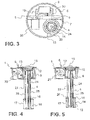
- a conveyor device 1 according to the invention is shown.
- the conveying device 1 has a metallic housing 6 and a metallic intake pipe 4.
- a coarse filter 16 is provided, which has a sieve 17.
- the housing 6 has a flange 12, with which the housing 6 may be sealed against a corresponding flange, for example, to a tank order.
- a lid 15 is also provided, which are opened and through which, for example, a maintenance of the conveyor device 1 according to the invention can be carried out.
- a filter (not shown here) in the conveying device 1 can be replaced by the cover 15.
- the Fig. 2 shows a section through a conveyor device according to the invention 1. Again, the housing 6 and the intake pipe 4 can be seen.
- a metallic base plate 7 is provided, on which the essential components of the conveying device according to the invention are attached.
- the filter housing 13 and a filter 14 is included. Through the lid 15 in the housing 6 access directly to the filter housing 13 is possible, so that the filter 14 can be replaced quickly and easily.
- the filter housing 13 is sealed against the housing 6 such that the interior of the filter housing 13 is closed even with the lid 15 open relative to the interior of the housing 6.
- the filter 14 may be designed as a filter cartridge.
- the conveyor device 1 and the filter 14 may each have connection elements which, when the filter 14 is installed, produce at least one fluidic connection between the filter 14 and the conveyor device 15.
- the connection elements may be further carried out so that both the filter 14 and the conveyor 11 are sealed fluid-tight, as soon as the filter 14 is removed from the conveyor device 1 out. In this way it can be ensured that reducing agent does not escape from the conveying device 1 or from the filter 14 when the filter 14 is removed from the conveying device 1. In such an embodiment, a change of the filter 14 can be done safely and reliably.
- a compensation element 36 may be provided in the lid 15, a compensation element 36 may be provided.
- a compensating element 36 may, for example, be designed as an elastic filling material (for example as a porous rubber) in order to compensate for expansions of the reducing agent during freezing, so that the conveying device 1 according to the invention is not damaged by the freezing.
- all the components of the filter device 1 except the filter 14 are designed and dimensioned so that they need not be replaced during the life of the conveyor 1, and the housing 6 of the filter device 1 (apart from the lid 15) fixed , permanently and without destruction is not openable.
- the housing 6 has a flange 12 for connecting the housing 6, for example to a reducing agent tank.
- a pressure line connection 5 is provided, through which pressurized reducing agent can be conveyed out of the conveyor device 1.
- the pressure line connection 5 may be provided directly on the metallic base plate 7 or, if the metallic base plate 7 is designed as a cast part, be molded onto it. Thus, a very good heat transfer between the pressure line connection 5 and the metallic base plate 7 can be achieved.
- the pressure line connection 5 can then via the metallic Base plate 7 passively (by means of heat conduction) with heated.
- the pressure line connection 5 is preferably made of a good heat conductive material.
- the pressure line connection 5 is made of aluminum or stainless steel.
- a return line 21 leaves the housing 6. Through the return line 21, reducing agent can pass back out of the conveyor device 1 into a reducing agent tank when the return valve 20 is open.
- the intake pipe 4 is constructed of an inner pipe 25 and an outer support pipe 26. Between the inner conduit 25 and the holding tube 26, a (single PTC) heating element 24 is provided which extends along the intake pipe 4 into the housing 6 and the filter housing 13, respectively. Level sensor electrodes 22, by means of which the fill level of reducing agent can be determined, are also provided on the intake pipe 4. At the suction end 18 of the intake pipe 4 is also according to Fig. 2 a coarse filter 16 having a sieve 17 is provided.
- connection point 39 between the filter inner housing 40 and inner conduit 25 is regularly very important for the tightness of the conveying device 1 according to the invention.
- This joint 39 should either be soldered or laser welded and / or designed with at least one O-ring seal. The tightness of this connection point 39 is required because otherwise reducing agent could penetrate into the housing 6 of the conveyor device 1 during operation. If the joint 39 is soldered or laser welded, the heating element 24 after assembly is not accessible without destroying the conveyor device 1. When the joint 39 is formed with an O-ring seal, the heating element 24 of the conveyer 1 can be exchanged.
- the suction of reducing agent takes place in the embodiment of the conveyor device 1 shown here at the suction end 18 of the intake manifold 4 by radial bores 37.
- the radial bores 37 extend through the outer support tube 26, that inner conduit 25 and a plug 28, the outer support tube 26th and the inner conduit 25 in the lower region at the suction end 18 connects to each other and at the same time seals the gap between outer support tube 26 and inner conduit 25 from the environment.
- a plurality of radial bores 37 may be provided at the suction end 18 .
- the plug 38 is preferably metallic and soldered or welded to the inner conduit 25 and the outer support tube 26.
- Fig. 3 shows a further section through the conveying device 1 according to the invention, wherein the section was passed through the housing 6 as in Fig. 2 is indicated.
- the metallic base plate 7 to recognize, on which the pump 8, the return valve 20, the pressure sensor 19 and the filter housing 13 are provided.
- channels 9 are provided through which fluidic connections between the pump 8, pressure sensor 19, filter housing 13 and return valve 20 are made.
- the filter housing 13 the filter 14 is arranged. Seen from above, the intake pipe 4 and the heating element 24 can be seen within the filter housing.
- the individual components of the system such as, for example, the filter housing 13, the housing 6 or the intake pipe 4, are in heat-conducting contact via contact surfaces 29.
- the contact surface 29 can also be used to transfer heat from one component to the next component. If components of the system are spaced from one another by design, it is also possible to produce a heat-conducting connection via thermal bridges 30. Such a thermal bridge 30 is shown here by way of example between metallic base plate 7 and pump 8.
- the 4 and 5 show sections through further preferred embodiments of the conveyor device according to the invention 1.
- the housing 6, the pressure line connection 5, the filter housing 13, the lid 15, the flange 12 and the return valve 20 can be seen.
- the intake manifold 4 with inner conduit 25, outer support tube 26 and heating element 24 is also recognizable.
- a coarse filter 16 having a sieve 17 is provided.
- the embodiment according to Fig. 4 a return line 21, which leads into the space between coarse filter 16 and intake pipe 4.
- flushing of the coarse filter 16 can take place from the inside during the return of reducing agent through the return line 21.
- a particularly good permeability of the coarse filter 16 can be ensured even over a long period of operation of the conveyor device 1 according to the invention.
- the embodiment according to Fig. 5 has as a special feature on an elongated level sensor electrode 22, through which the level 23 of a reducing agent tank is continuously determined. Furthermore, in the embodiment according to Fig. 5 a filter 14 in the space between the coarse filter 16 and intake 4 at the suction end 18 of the intake 4 is provided. In this way, a filter 14 in the filter housing 13 can be avoided. This is the system according to Fig. 5 especially inexpensive. If, in addition, an opening is present below the suction end 10 in a reducing agent tank, replacement of the filter 14 can be very simple, without the conveying device 1 according to the invention having to be opened via the cover 15. The opening of a tank down has the additional advantage that deposits that form in the tank, are easily transported out of the tank.
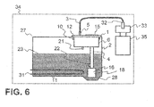
- a motor vehicle 34 having an internal combustion engine 35 and an exhaust system 33 is depicted.
- the exhaust system 33 is supplied via an injector 32 reducing agent.
- the exhaust system 33 is provided to perform a selective catalytic reduction.
- the motor vehicle 34 has a tank arrangement 27, in which a conveyor device 1 is arranged.
- the conveyor device 1 closes an opening 10 of the reducing agent tank 2 of the tank assembly 27, wherein a flange 12 of the conveyor device 1 connects to a corresponding counter flange at the opening 10.
- the lid 15 the intake pipe 4, the coarse filter 16, the return line 21 and the housing 6 can be seen.
- a level sensor electrode 22 is also attached, with which a level 23 in the reducing agent tank 2 can be determined.
- the reducing agent tank 2 has a tank bottom 11, which in the region of the suction end 18 of the suction line 4 has a recess 28, so that the tank can be almost completely emptied.
- a tank heater 31 may be provided which warms up the reducing agent in the tank in addition to the heater via the conveying device 1 according to the invention. Such heating of the reducing agent in the reducing agent tank 2 can be done for example with the aid of cooling water.
- a line 3 Connected to the pressure line connection 5 of the conveying device 1 is a line 3, through which pressurized reducing agent is conveyed from the conveying device 1 to the injector 32 into the exhaust system 33.
- a double O-ring seal is regularly provided, consisting of two parallel preferably concentric juxtaposed O-ring seals.
- Such a double O-ring seal can also seal the connection between the conveying device 1 and the reducing agent tank 2, if this is below the maximum level 23 of the reducing agent tank 2.
- the reducing agent tank 2 is in the region of the opening 2 regularly made of metal. The sealing by means of the O-ring seal thus takes place between two metallic surfaces. Metallic surfaces can be more precisely manufactured than plastic surfaces. Accordingly, can be done with a double O-ring seal here a correspondingly tight seal.
- the connection between the conveying device 1 and reducing agent tank 2 at the opening 10 is preferably carried out by means of an SAE screw connection.
- the conveying device according to the invention and the tank arrangement according to the invention are particularly simple and inexpensive and at the same time enable a high degree of safety and high reliability in the provision of reducing agent. They thus represent a significant advance over the prior art.
Landscapes
- Engineering & Computer Science (AREA)
- Chemical & Material Sciences (AREA)
- Mechanical Engineering (AREA)
- Combustion & Propulsion (AREA)
- Chemical Kinetics & Catalysis (AREA)
- General Engineering & Computer Science (AREA)
- Toxicology (AREA)
- Health & Medical Sciences (AREA)
- Transportation (AREA)
- Exhaust Gas After Treatment (AREA)
- Thermotherapy And Cooling Therapy Devices (AREA)
- Sampling And Sample Adjustment (AREA)
- Control Of Resistance Heating (AREA)
Claims (14)
- Dispositif d'acheminement (1) pour un agent de réduction comportant un boîtier (6), comprenant au moins un tube d'aspiration métallique (4) fixé extérieurement et un raccord extérieur de conduite de pression (5), un élément chauffant allongé (24) étant disposé à proximité du tube d'aspiration (4),
caractérisé
en ce qu'une plaque de base métallique (7) est disposée dans le boîtier (6), sur laquelle sont prévus au moins une pompe (8) et des canaux (9), le boîtier (6) étant métallique, et le tube d'aspiration (4), le boîtier (6), la plaque de base métallique (7) et la pompe (8) étant en contact de conduction de chaleur les uns avec les autres. - Dispositif d'acheminement (1) selon la revendication 1, dans lequel des canaux (9) sont ménagés dans la plaque de base métallique (7), et le tube d'aspiration (4), la pompe (8) et le raccord de conduite (5) sont en liaison fluidique par le biais des canaux (9) dans la plaque de base métallique (7).
- Dispositif d'acheminement (1) selon l'une quelconque des revendications précédentes, dans lequel un boîtier de filtre métallique (13) est en liaison de conduction de chaleur avec la plaque de base (7), dans lequel boîtier de filtre peut être disposé un filtre (14).
- Dispositif d'acheminement (1) selon la revendication 3, dans lequel le tube d'aspiration (4) s'étend conjointement avec l'élément chauffant (24) dans le boîtier de filtre (13).
- Dispositif d'acheminement (1) selon l'une quelconque des revendications précédentes, dans lequel un filtre grossier métallique (16) pour des particules supérieures à 30 µm est réalisé sur le tube d'aspiration (4).
- Dispositif d'acheminement (1) selon la revendication 5, dans lequel le filtre grossier métallique (16) comporte un tamis, lequel entoure à la manière d'un pot une extrémité d'aspiration (18) du tube d'aspiration (4).
- Dispositif d'acheminement (1) selon l'une quelconque des revendications précédentes, dans lequel au moins une électrode de capteur de niveau (22) est fixée au tube d'aspiration (5), à l'aide de laquelle un niveau de remplissage (23) d'un agent de réduction dans le réservoir d'agent de réduction (2) peut être déterminé.
- Dispositif d'acheminement (1) selon l'une quelconque des revendications précédentes, dans lequel l'élément chauffant (24) est un élément chauffant PTC (positive temperature coefficient - coefficient de température positif).
- Dispositif d'acheminement (1) selon l'une quelconque des revendications précédentes, dans lequel le tube d'aspiration (4) comporte un tube de conduite intérieur (25) et un tube de maintien extérieur (26), l'élément chauffant (24) étant disposé entre le tube de conduite (25) et le tube de maintien (26).
- Dispositif d'acheminement (1) selon l'une quelconque des revendications précédentes, dans lequel le boîtier (6) et au moins le tube d'aspiration (4) ou un tube de retenue extérieur (26) sont réalisés d'une seule pièce.
- Dispositif d'acheminement (1) selon l'une quelconque des revendications précédentes, dans lequel une conduite de retour (21) pourvue d'une soupape de retour (20) est prévue, et la soupape de retour (20) peut fonctionner en tant que chauffage pour chauffer l'agent de réduction.
- Agencement de réservoir (27) comprenant un réservoir d'agent de réduction (2) pourvu d'une ouverture de réservoir (10) ainsi qu'un dispositif d'acheminement (1) selon l'une quelconque des revendications précédentes, l'ouverture de réservoir (10) étant fermée par le dispositif d'acheminement (1) et le tube d'aspiration (4) s'étendant jusqu'au fond (11) du réservoir d'agent de réduction (2).
- Agencement de réservoir (27) selon la revendication 12, dans lequel le boîtier (6) est disposé pour plus de 50 % en dessous de l'ouverture de réservoir (10).
- Véhicule automobile (34), comprenant un moteur à combustion interne (35) pourvu d'un système d'échappement (33) qui est conçu pour effectuer une réduction catalytique sélective de composés d'oxyde d'azote, le véhicule automobile (34) comprenant un agencement de réservoir (27) selon la revendication 12 ou 13 ou un dispositif d'acheminement (1) selon l'une quelconque des revendications 1 à 11.
Applications Claiming Priority (2)
| Application Number | Priority Date | Filing Date | Title |
|---|---|---|---|
| DE102009041179A DE102009041179A1 (de) | 2009-09-11 | 2009-09-11 | Fördervorrichtung für ein Reduktionsmittel |
| PCT/EP2010/062943 WO2011029780A1 (fr) | 2009-09-11 | 2010-09-03 | Dispositif d'acheminement pour un agent de réduction |
Publications (2)
| Publication Number | Publication Date |
|---|---|
| EP2475853A1 EP2475853A1 (fr) | 2012-07-18 |
| EP2475853B1 true EP2475853B1 (fr) | 2014-11-19 |
Family
ID=43034119
Family Applications (2)
| Application Number | Title | Priority Date | Filing Date |
|---|---|---|---|
| EP20100754298 Not-in-force EP2475853B1 (fr) | 2009-09-11 | 2010-09-03 | Dispositif d'acheminement pour un agent de réduction |
| EP20100752550 Not-in-force EP2475850B1 (fr) | 2009-09-11 | 2010-09-03 | Dispositif d'acheminement pour un agent de réduction |
Family Applications After (1)
| Application Number | Title | Priority Date | Filing Date |
|---|---|---|---|
| EP20100752550 Not-in-force EP2475850B1 (fr) | 2009-09-11 | 2010-09-03 | Dispositif d'acheminement pour un agent de réduction |
Country Status (11)
| Country | Link |
|---|---|
| US (2) | US9038374B2 (fr) |
| EP (2) | EP2475853B1 (fr) |
| JP (2) | JP2013504707A (fr) |
| KR (2) | KR101345972B1 (fr) |
| CN (2) | CN102575560B (fr) |
| DE (1) | DE102009041179A1 (fr) |
| ES (1) | ES2528247T3 (fr) |
| IN (1) | IN2012DN02109A (fr) |
| PL (1) | PL2475850T3 (fr) |
| RU (2) | RU2505687C2 (fr) |
| WO (2) | WO2011029780A1 (fr) |
Families Citing this family (43)
| Publication number | Priority date | Publication date | Assignee | Title |
|---|---|---|---|---|
| DE102010014314A1 (de) | 2010-04-09 | 2011-10-13 | Emitec Gesellschaft Für Emissionstechnologie Mbh | Vorrichtung zur Bereitstellung von flüssigem Reduktionsmittel |
| DE102010062333A1 (de) * | 2010-12-02 | 2012-06-06 | Robert Bosch Gmbh | Vorrichtung zur Versorgung eines Abgasnachbehandlungssystems mit einem Reduktionsmittel |
| DE102011010640A1 (de) * | 2011-02-09 | 2012-08-09 | Emitec France S.A.S | Fördereinheit zur Förderung von Reduktionsmittel |
| DE102011014634A1 (de) * | 2011-03-21 | 2012-09-27 | Albonair Gmbh | Abgasnachbehandlungssystem |
| CN102758672A (zh) * | 2011-04-29 | 2012-10-31 | 北京理工大学 | Scr泵喷嘴装置 |
| DE102011112326A1 (de) * | 2011-09-02 | 2013-03-07 | Emitec Gesellschaft Für Emissionstechnologie Mbh | Vorrichtung zur Bereitstellung von flüssigem Reduktionsmittel mit einem Partikelsieb |
| DE102011119772A1 (de) * | 2011-11-30 | 2013-06-06 | Emitec Gesellschaft Für Emissionstechnologie Mbh | Vorrichtung zur Bereitstellung vonReduktionsmittel |
| CN103291421B (zh) | 2012-02-23 | 2016-06-08 | 天纳克(苏州)排放系统有限公司 | 空气辅助式还原剂计量喷射系统 |
| US10418649B2 (en) * | 2012-03-09 | 2019-09-17 | Nissan Motor Co., Ltd. | Fuel cell stack and seal plate used for the same |
| JP2013221425A (ja) * | 2012-04-13 | 2013-10-28 | Denso Corp | 排気浄化装置のインジェクタ制御装置 |
| CN103511033A (zh) * | 2012-06-28 | 2014-01-15 | 安徽华菱汽车有限公司 | 汽车及其scr系统 |
| JP5871072B2 (ja) * | 2012-08-10 | 2016-03-01 | トヨタ自動車株式会社 | 内燃機関の添加剤供給装置 |
| DE102012110585A1 (de) * | 2012-11-06 | 2014-05-08 | Emitec Denmark A/S | Vorrichtung zur Bereitstellung eines flüssigen Additivs und Verfahren zum Heizen des Additivs |
| DE102012111919A1 (de) | 2012-12-07 | 2014-06-12 | Emitec Gesellschaft Für Emissionstechnologie Mbh | Verfahren zum Betrieb einer Vorrichtung zur Bereitstellung eines flüssigen Additivs |
| DE102012111917A1 (de) | 2012-12-07 | 2014-06-12 | Emitec Gesellschaft Für Emissionstechnologie Mbh | Verfahren zur Entleerung einer Vorrichtung zur Bereitstellung eines flüssigen Additivs |
| DE102012224095A1 (de) * | 2012-12-20 | 2014-06-26 | Continental Automotive Gmbh | Reduktionsmitteltank |
| DE102013001237B4 (de) * | 2013-01-25 | 2015-04-16 | Kautex Textron Gmbh & Co. Kg | Filtervorrichtung für einen Flüssigkeitsbehälter, insbesondere für wässrige Harnstofflösung |
| CN103291424B (zh) * | 2013-06-13 | 2015-12-09 | 中国第一汽车股份有限公司无锡油泵油嘴研究所 | 一种还原剂供应单元的加热解冻装置 |
| US9468875B2 (en) | 2014-01-14 | 2016-10-18 | Caterpillar Inc. | Filter system and filtration method for fluid reservoirs |
| US20150218990A1 (en) * | 2014-02-03 | 2015-08-06 | Caterpillar Inc. | Diesel exhaust fluid filter permeability detection strategy and machine using same |
| CN204186452U (zh) * | 2014-06-27 | 2015-03-04 | 康明斯排放处理公司 | 还原剂供应装置和还原剂供应系统及发动机系统 |
| US20150023843A1 (en) * | 2014-10-09 | 2015-01-22 | Caterpillar Inc. | Reductant supply system |
| KR200480838Y1 (ko) * | 2014-11-21 | 2016-07-22 | 대우조선해양 주식회사 | 석션 파이프 일체형 레벨 스위치 및 그 설치구조 |
| JP6187505B2 (ja) * | 2015-03-02 | 2017-08-30 | トヨタ自動車株式会社 | 排気浄化装置 |
| DE102015205499A1 (de) * | 2015-03-26 | 2016-09-29 | Robert Bosch Gmbh | Fördermodul zum Fördern von wasserhaltigen Flüssigkeiten |
| EP3088231A1 (fr) * | 2015-04-28 | 2016-11-02 | Inergy Automotive Systems Research (Société Anonyme) | Dispositif de recharge de précurseur d'ammoniac |
| EP3168439B1 (fr) * | 2015-11-16 | 2019-03-20 | Wema System AS | Manchon de débullage pour des détecteurs de fluide et systèmes de détection comportant un tel dispositif |
| CN108495981B (zh) | 2015-12-10 | 2021-04-30 | 大陆汽车有限公司 | 用于还原剂的箱系统 |
| GB2545674B (en) | 2015-12-21 | 2021-03-31 | Bamford Excavators Ltd | Dosing module |
| CN108699941B (zh) * | 2016-02-09 | 2021-10-22 | 考特克斯·特克斯罗恩有限公司及两合公司 | 用于储藏辅助液体及将辅助液体供给机动车内燃机或机动车内燃机部件的系统 |
| JP6373291B2 (ja) * | 2016-03-02 | 2018-08-15 | 日立建機株式会社 | 建設機械 |
| US9804004B1 (en) | 2016-05-13 | 2017-10-31 | Deere & Company | Fluid quality sensor and cover assembly |
| CN105909351A (zh) * | 2016-05-31 | 2016-08-31 | 苏州新力迈特汽车系统有限公司 | 一种汽车scr后处理系统用尿素滤清器 |
| CN106194706B (zh) * | 2016-09-22 | 2018-09-28 | 凯龙高科技股份有限公司 | 一种带阻尼孔的压力开关 |
| DE102017201124A1 (de) * | 2017-01-25 | 2018-07-26 | Robert Bosch Gmbh | Fördermodul für ein Dosiersystem zum Eindosieren eines Reduktionsmittels in den Abgasstrang eines Kraftfahrzeugs sowie Dosiersystem |
| DE102017203283A1 (de) * | 2017-03-01 | 2018-09-06 | Robert Bosch Gmbh | Heizeinrichtung |
| DE102017114333A1 (de) * | 2017-06-28 | 2019-01-03 | Kautex Textron Gmbh & Co. Kg | Betriebsflüssigkeitstank |
| DE102018208643A1 (de) * | 2018-05-30 | 2019-12-05 | Röchling Automotive SE & Co. KG | Kfz-Tankbaugruppe und Entnahmemodul mit einem porösen Förderkörper |
| CN108869114A (zh) * | 2018-07-09 | 2018-11-23 | 慈溪市三新汽车零部件有限公司 | 一种燃油加热供给系统 |
| FR3088675B1 (fr) * | 2018-11-15 | 2020-10-30 | Continental Automotive France | Module de dosage d'agent reducteur avec revetement de transfert thermique |
| KR102197079B1 (ko) * | 2019-08-06 | 2020-12-30 | 주식회사 현대기전 | 고상우레아에 기반한 선택적환원촉매 탈질 설비용 암모니아 환원제 공급 설비 시스템의 용융우레아 공급장치, 이의 공급 운용 방법, 및 이를 포함하는 선택적환원촉매 탈질 설비용 암모니아 환원제 공급 설비 시스템 |
| KR102197077B1 (ko) * | 2019-08-06 | 2020-12-30 | 주식회사 현대기전 | 선택적환원촉매 탈질 설비용 암모니아 환원제 공급 설비 시스템의 고상우레아 용융장치, 및 이를 포함하는 선택적환원촉매 탈질 설비용 암모니아 환원제 공급 설비 시스템 |
| CN112145261B (zh) * | 2020-08-05 | 2021-12-07 | 中船澄西船舶修造有限公司 | 一种船用低温自清洁式尿素舱 |
Family Cites Families (42)
| Publication number | Priority date | Publication date | Assignee | Title |
|---|---|---|---|---|
| US3633622A (en) * | 1970-09-03 | 1972-01-11 | Gen Electric | Valve mechanism for dishwasher |
| DE3220268C1 (de) * | 1982-05-28 | 1983-11-17 | Tokyo Shibaura Denki K.K., Kawasaki, Kanagawa | Warmhaltetopf oder -kanne |
| US4807584A (en) * | 1984-11-30 | 1989-02-28 | Davco Manufacturing Corp. | Fuel tank heating system |
| JPH0392686A (ja) * | 1989-09-05 | 1991-04-17 | Mitsubishi Electric Corp | 電磁弁 |
| US5201341A (en) * | 1991-03-19 | 1993-04-13 | Nippon Soken, Inc. | Electromagnetic type fluid flow control valve |
| US5718208A (en) * | 1996-09-16 | 1998-02-17 | Ford Motor Company | Fuel vapor management system |
| JP3303708B2 (ja) * | 1997-01-31 | 2002-07-22 | 三菱電機株式会社 | 車両用燃料供給装置 |
| US6063350A (en) * | 1997-04-02 | 2000-05-16 | Clean Diesel Technologies, Inc. | Reducing nox emissions from an engine by temperature-controlled urea injection for selective catalytic reduction |
| US6065452A (en) * | 1997-11-19 | 2000-05-23 | Mitsubishi Denki Kabushiki Kaisha | Fuel feeder for vehicles |
| WO2000001941A1 (fr) * | 1998-07-02 | 2000-01-13 | Mitsubishi Denki Kabushiki Kaisha | Appareil d'alimentation en carburant d'un vehicule |
| JP2000027627A (ja) * | 1998-07-13 | 2000-01-25 | Hino Motors Ltd | 排気ガス浄化触媒用還元剤保温装置及びそれを組込んだ排気ガス浄化装置 |
| DE19946900A1 (de) * | 1999-06-22 | 2000-12-28 | Bosch Gmbh Robert | Vorrichtung zur Dosierung eines Reduktionsmittels |
| DE10139139A1 (de) * | 2001-08-09 | 2003-06-12 | Bosch Gmbh Robert | Dosiersystem zur Dosierung eines Reduktionsmittels für eine Abgasnachbehandlung |
| US20040113731A1 (en) * | 2002-10-09 | 2004-06-17 | David Moyer | Electromagnetic valve system |
| JP2004190491A (ja) * | 2002-12-06 | 2004-07-08 | Hitachi Unisia Automotive Ltd | 燃料供給装置 |
| DE50212911D1 (de) * | 2002-12-23 | 2008-11-27 | Grundfos Nonox As | Dosierpumpenaggregat |
| US6901748B2 (en) * | 2003-05-14 | 2005-06-07 | Detroit Diesel Corporation | Heater system for diesel engines having a selective catalytic reduction system |
| JP3751962B2 (ja) * | 2003-09-05 | 2006-03-08 | 日産ディーゼル工業株式会社 | エンジンの排気浄化装置 |
| WO2005093382A1 (fr) * | 2004-03-29 | 2005-10-06 | Nissan Diesel Motor Co., Ltd. | Structure pour conteneur d’agent réducteur |
| JP4379205B2 (ja) * | 2004-05-27 | 2009-12-09 | トヨタ自動車株式会社 | 電磁弁制御装置 |
| DE102004051746A1 (de) * | 2004-10-23 | 2006-04-27 | Robert Bosch Gmbh | Tankmodul für ein Reduktionsmittel und Dosiersystem |
| JP3686668B1 (ja) * | 2004-10-29 | 2005-08-24 | 日産ディーゼル工業株式会社 | 還元剤容器の構造 |
| JP4313289B2 (ja) * | 2004-11-24 | 2009-08-12 | 本田技研工業株式会社 | 燃料タンクのポンプモジュール構造 |
| US7836684B2 (en) * | 2005-06-04 | 2010-11-23 | Eichenauer Heizelemente Gmbh & Co. Kg | Urea supply system for a waste gas cleaning catalyst and heating insert suitable therefor |
| DE102005037201A1 (de) * | 2005-08-06 | 2007-02-22 | Eichenauer Heizelemente Gmbh & Co. Kg | Heizsystem |
| DE102006027487A1 (de) * | 2005-09-12 | 2007-03-15 | Robert Bosch Gmbh | Fahrzeugtank für ein flüssiges Reduktionsmittel, insbesondere für eine Harnstofflösung |
| DE102006012855A1 (de) * | 2006-03-21 | 2007-09-27 | Robert Bosch Gmbh | Verfahren und Dosiersystem zur Schadstoffreduktion in Kraftfahrzeugabgasen |
| BRPI0710991A2 (pt) * | 2006-04-27 | 2011-05-24 | Volvo Lastvagnar Ab | um receptáculo de lìquido para um veìculo |
| US8850797B2 (en) * | 2006-06-08 | 2014-10-07 | Inergy Automotive Systems Research S.A. | Engine exhaust gas additive storage system |
| DE102006032099A1 (de) * | 2006-07-11 | 2008-01-24 | Siemens Ag | Fördereinheit zum Fördern von Kraftstoff |
| DE102006032101A1 (de) * | 2006-07-11 | 2008-01-24 | Siemens Ag | Fördereinheit zum Fördern von Kraftstoff |
| US7549438B2 (en) * | 2006-11-03 | 2009-06-23 | Gm Global Technology Operations, Inc. | Valve heated by split solenoid |
| JP2008115784A (ja) * | 2006-11-06 | 2008-05-22 | Hino Motors Ltd | 尿素水貯蔵装置 |
| DE102006061736A1 (de) * | 2006-12-28 | 2008-07-03 | Robert Bosch Gmbh | Fördermodul für selektive katalytische Reduktion |
| DE102007022585A1 (de) * | 2007-05-14 | 2008-11-27 | Robert Bosch Gmbh | Leitungsdurchführung durch einen Heiztopfdeckel eines Heiztopfs eines Reduktionsmitteltanks |
| DE102007027413B4 (de) * | 2007-06-11 | 2016-10-20 | Eichenauer Heizelemente Gmbh & Co. Kg | Reduktionsmittelversorgungssystem für einen Abgasreinigungskatalysator eines Verbrennungsmotors |
| DE102007031413A1 (de) * | 2007-07-05 | 2009-01-08 | Eichenauer Heizelemente Gmbh & Co. Kg | Reduktionsmittelversorgungssystem für einen Abgasreinigungskatalysator eines Verbrennungsmotors und Verfahren zum Beheizen seiner Flüssigkeitsleitungen |
| JP2009057863A (ja) * | 2007-08-30 | 2009-03-19 | Hino Motors Ltd | 尿素水供給管 |
| DE102007050272A1 (de) * | 2007-10-18 | 2009-04-23 | Robert Bosch Gmbh | Tank zur Bevorratung eines Reduktionsmittels |
| DE102008005196A1 (de) * | 2008-01-18 | 2009-07-23 | Dbk David + Baader Gmbh | Tankentnahmesystem mit elektrischer und fluidischer Heizvorrichtung |
| DE102008045958B4 (de) * | 2008-09-04 | 2013-01-03 | Continental Automotive Gmbh | Reduktionsmittelzuführsystem für einen SCR-Katalysator einer Brennkraftmaschine |
| US8359831B2 (en) * | 2008-10-31 | 2013-01-29 | Ti Group Automotive Systems, L.L.C. | Reactant delivery for engine exhaust gas treatment |
-
2009
- 2009-09-11 DE DE102009041179A patent/DE102009041179A1/de not_active Withdrawn
-
2010
- 2010-09-03 KR KR1020127009282A patent/KR101345972B1/ko not_active IP Right Cessation
- 2010-09-03 JP JP2012528328A patent/JP2013504707A/ja active Pending
- 2010-09-03 EP EP20100754298 patent/EP2475853B1/fr not_active Not-in-force
- 2010-09-03 CN CN201080040111.5A patent/CN102575560B/zh not_active Expired - Fee Related
- 2010-09-03 ES ES10752550.3T patent/ES2528247T3/es active Active
- 2010-09-03 CN CN201080040110.0A patent/CN102498270B/zh not_active Expired - Fee Related
- 2010-09-03 JP JP2012528325A patent/JP5684812B2/ja not_active Expired - Fee Related
- 2010-09-03 RU RU2012113926/06A patent/RU2505687C2/ru not_active IP Right Cessation
- 2010-09-03 WO PCT/EP2010/062943 patent/WO2011029780A1/fr active Application Filing
- 2010-09-03 IN IN2109DEN2012 patent/IN2012DN02109A/en unknown
- 2010-09-03 WO PCT/EP2010/062920 patent/WO2011029774A1/fr active Application Filing
- 2010-09-03 RU RU2012113925/06A patent/RU2504669C2/ru not_active IP Right Cessation
- 2010-09-03 PL PL10752550T patent/PL2475850T3/pl unknown
- 2010-09-03 EP EP20100752550 patent/EP2475850B1/fr not_active Not-in-force
- 2010-09-03 KR KR1020127008757A patent/KR101331687B1/ko not_active IP Right Cessation
-
2012
- 2012-03-12 US US13/417,500 patent/US9038374B2/en not_active Expired - Fee Related
- 2012-03-12 US US13/417,502 patent/US20120181261A1/en not_active Abandoned
Also Published As
| Publication number | Publication date |
|---|---|
| EP2475850A1 (fr) | 2012-07-18 |
| KR20120053526A (ko) | 2012-05-25 |
| US20120186237A1 (en) | 2012-07-26 |
| KR101331687B1 (ko) | 2013-11-20 |
| WO2011029774A1 (fr) | 2011-03-17 |
| RU2012113925A (ru) | 2013-10-20 |
| IN2012DN02109A (fr) | 2015-08-21 |
| CN102498270A (zh) | 2012-06-13 |
| JP2013504706A (ja) | 2013-02-07 |
| PL2475850T3 (pl) | 2015-04-30 |
| KR101345972B1 (ko) | 2014-01-02 |
| DE102009041179A1 (de) | 2011-03-24 |
| JP2013504707A (ja) | 2013-02-07 |
| RU2505687C2 (ru) | 2014-01-27 |
| US20120181261A1 (en) | 2012-07-19 |
| EP2475850B1 (fr) | 2014-11-05 |
| US9038374B2 (en) | 2015-05-26 |
| CN102575560B (zh) | 2015-04-08 |
| RU2504669C2 (ru) | 2014-01-20 |
| CN102575560A (zh) | 2012-07-11 |
| WO2011029780A1 (fr) | 2011-03-17 |
| ES2528247T3 (es) | 2015-02-05 |
| JP5684812B2 (ja) | 2015-03-18 |
| EP2475853A1 (fr) | 2012-07-18 |
| KR20120076353A (ko) | 2012-07-09 |
| RU2012113926A (ru) | 2013-10-20 |
| CN102498270B (zh) | 2014-04-09 |
Similar Documents
| Publication | Publication Date | Title |
|---|---|---|
| EP2475853B1 (fr) | Dispositif d'acheminement pour un agent de réduction | |
| DE102008055190B4 (de) | Montageaufbau für ein Einspritzventil | |
| EP2689117B1 (fr) | Unité fonctionnelle pour un réservoir d'agent réducteur ainsi que réservoir d'agent réducteur | |
| EP2524117A1 (fr) | Ensemble réservoir et système de dosage pour réducteur | |
| DE202007019641U1 (de) | System zur Lagerung von Motorgasadditiven | |
| WO2011160836A1 (fr) | Module de réservoir pour un réservoir de liquide | |
| DE102012108273A1 (de) | Kunststofftank für eine Betriebsflüssigkeit | |
| DE102011010640A1 (de) | Fördereinheit zur Förderung von Reduktionsmittel | |
| EP3011153B1 (fr) | Réservoir de stockage pourvu d'un dispositif de chauffe | |
| EP2785990B1 (fr) | Dispositif d'alimentation en agent réducteur | |
| DE102011010641A1 (de) | Injektor für eine Harnstoff-Wasser-Lösung | |
| DE102014108074A1 (de) | Heizmodul und Tanksystem | |
| DE102008042954A1 (de) | Dosiersystem für ein flüssiges Medium, insbesondere Harnstoff-Wasser-Lösung | |
| EP3211191B1 (fr) | Récipient pouvant être chauffé pour un fluide | |
| DE102012002061A1 (de) | Dosierventil für einfriergefährdete Additive | |
| EP2954178A1 (fr) | Valve de dosage pour des additifs sensibles au gel | |
| WO2011086023A1 (fr) | Dispositif pourvu d'un injecteur pour un agent de réduction liquide | |
| WO2019029881A1 (fr) | Dispositif de réservoir pour système de post-traitement des gaz d'échappement | |
| EP3025035B1 (fr) | Dispositif pour stocker et mettre à disposition un réducteur de liquide | |
| WO2014048610A1 (fr) | Module de dosage | |
| DE102016001473A1 (de) | Tank-Fördermodul für ein Reduktionsmittel | |
| DE102018214157A1 (de) | Tankanordnung | |
| DE102012221866A1 (de) | Anordnung zur Nachbehandlung des Abgases einer Brennkraftmaschine |
Legal Events
| Date | Code | Title | Description |
|---|---|---|---|
| PUAI | Public reference made under article 153(3) epc to a published international application that has entered the european phase |
Free format text: ORIGINAL CODE: 0009012 |
|
| 17P | Request for examination filed |
Effective date: 20120320 |
|
| AK | Designated contracting states |
Kind code of ref document: A1 Designated state(s): AL AT BE BG CH CY CZ DE DK EE ES FI FR GB GR HR HU IE IS IT LI LT LU LV MC MK MT NL NO PL PT RO SE SI SK SM TR |
|
| DAX | Request for extension of the european patent (deleted) | ||
| GRAP | Despatch of communication of intention to grant a patent |
Free format text: ORIGINAL CODE: EPIDOSNIGR1 |
|
| INTG | Intention to grant announced |
Effective date: 20140801 |
|
| GRAS | Grant fee paid |
Free format text: ORIGINAL CODE: EPIDOSNIGR3 |
|
| GRAA | (expected) grant |
Free format text: ORIGINAL CODE: 0009210 |
|
| AK | Designated contracting states |
Kind code of ref document: B1 Designated state(s): AL AT BE BG CH CY CZ DE DK EE ES FI FR GB GR HR HU IE IS IT LI LT LU LV MC MK MT NL NO PL PT RO SE SI SK SM TR |
|
| REG | Reference to a national code |
Ref country code: GB Ref legal event code: FG4D Free format text: NOT ENGLISH |
|
| REG | Reference to a national code |
Ref country code: CH Ref legal event code: EP |
|
| REG | Reference to a national code |
Ref country code: AT Ref legal event code: REF Ref document number: 697170 Country of ref document: AT Kind code of ref document: T Effective date: 20141215 |
|
| REG | Reference to a national code |
Ref country code: IE Ref legal event code: FG4D Free format text: LANGUAGE OF EP DOCUMENT: GERMAN |
|
| REG | Reference to a national code |
Ref country code: DE Ref legal event code: R096 Ref document number: 502010008308 Country of ref document: DE Effective date: 20141224 |
|
| REG | Reference to a national code |
Ref country code: SE Ref legal event code: TRGR |
|
| REG | Reference to a national code |
Ref country code: NL Ref legal event code: VDEP Effective date: 20141119 |
|
| REG | Reference to a national code |
Ref country code: LT Ref legal event code: MG4D |
|
| PG25 | Lapsed in a contracting state [announced via postgrant information from national office to epo] |
Ref country code: ES Free format text: LAPSE BECAUSE OF FAILURE TO SUBMIT A TRANSLATION OF THE DESCRIPTION OR TO PAY THE FEE WITHIN THE PRESCRIBED TIME-LIMIT Effective date: 20141119 Ref country code: IS Free format text: LAPSE BECAUSE OF FAILURE TO SUBMIT A TRANSLATION OF THE DESCRIPTION OR TO PAY THE FEE WITHIN THE PRESCRIBED TIME-LIMIT Effective date: 20150319 Ref country code: NL Free format text: LAPSE BECAUSE OF FAILURE TO SUBMIT A TRANSLATION OF THE DESCRIPTION OR TO PAY THE FEE WITHIN THE PRESCRIBED TIME-LIMIT Effective date: 20141119 Ref country code: FI Free format text: LAPSE BECAUSE OF FAILURE TO SUBMIT A TRANSLATION OF THE DESCRIPTION OR TO PAY THE FEE WITHIN THE PRESCRIBED TIME-LIMIT Effective date: 20141119 Ref country code: PT Free format text: LAPSE BECAUSE OF FAILURE TO SUBMIT A TRANSLATION OF THE DESCRIPTION OR TO PAY THE FEE WITHIN THE PRESCRIBED TIME-LIMIT Effective date: 20150319 Ref country code: LT Free format text: LAPSE BECAUSE OF FAILURE TO SUBMIT A TRANSLATION OF THE DESCRIPTION OR TO PAY THE FEE WITHIN THE PRESCRIBED TIME-LIMIT Effective date: 20141119 Ref country code: NO Free format text: LAPSE BECAUSE OF FAILURE TO SUBMIT A TRANSLATION OF THE DESCRIPTION OR TO PAY THE FEE WITHIN THE PRESCRIBED TIME-LIMIT Effective date: 20150219 |
|
| PG25 | Lapsed in a contracting state [announced via postgrant information from national office to epo] |
Ref country code: GR Free format text: LAPSE BECAUSE OF FAILURE TO SUBMIT A TRANSLATION OF THE DESCRIPTION OR TO PAY THE FEE WITHIN THE PRESCRIBED TIME-LIMIT Effective date: 20150220 Ref country code: PL Free format text: LAPSE BECAUSE OF FAILURE TO SUBMIT A TRANSLATION OF THE DESCRIPTION OR TO PAY THE FEE WITHIN THE PRESCRIBED TIME-LIMIT Effective date: 20141119 Ref country code: LV Free format text: LAPSE BECAUSE OF FAILURE TO SUBMIT A TRANSLATION OF THE DESCRIPTION OR TO PAY THE FEE WITHIN THE PRESCRIBED TIME-LIMIT Effective date: 20141119 Ref country code: CY Free format text: LAPSE BECAUSE OF FAILURE TO SUBMIT A TRANSLATION OF THE DESCRIPTION OR TO PAY THE FEE WITHIN THE PRESCRIBED TIME-LIMIT Effective date: 20141119 Ref country code: HR Free format text: LAPSE BECAUSE OF FAILURE TO SUBMIT A TRANSLATION OF THE DESCRIPTION OR TO PAY THE FEE WITHIN THE PRESCRIBED TIME-LIMIT Effective date: 20141119 |
|
| PG25 | Lapsed in a contracting state [announced via postgrant information from national office to epo] |
Ref country code: EE Free format text: LAPSE BECAUSE OF FAILURE TO SUBMIT A TRANSLATION OF THE DESCRIPTION OR TO PAY THE FEE WITHIN THE PRESCRIBED TIME-LIMIT Effective date: 20141119 Ref country code: SK Free format text: LAPSE BECAUSE OF FAILURE TO SUBMIT A TRANSLATION OF THE DESCRIPTION OR TO PAY THE FEE WITHIN THE PRESCRIBED TIME-LIMIT Effective date: 20141119 Ref country code: DK Free format text: LAPSE BECAUSE OF FAILURE TO SUBMIT A TRANSLATION OF THE DESCRIPTION OR TO PAY THE FEE WITHIN THE PRESCRIBED TIME-LIMIT Effective date: 20141119 Ref country code: RO Free format text: LAPSE BECAUSE OF FAILURE TO SUBMIT A TRANSLATION OF THE DESCRIPTION OR TO PAY THE FEE WITHIN THE PRESCRIBED TIME-LIMIT Effective date: 20141119 Ref country code: CZ Free format text: LAPSE BECAUSE OF FAILURE TO SUBMIT A TRANSLATION OF THE DESCRIPTION OR TO PAY THE FEE WITHIN THE PRESCRIBED TIME-LIMIT Effective date: 20141119 |
|
| REG | Reference to a national code |
Ref country code: DE Ref legal event code: R097 Ref document number: 502010008308 Country of ref document: DE |
|
| REG | Reference to a national code |
Ref country code: FR Ref legal event code: PLFP Year of fee payment: 6 |
|
| PLBE | No opposition filed within time limit |
Free format text: ORIGINAL CODE: 0009261 |
|
| STAA | Information on the status of an ep patent application or granted ep patent |
Free format text: STATUS: NO OPPOSITION FILED WITHIN TIME LIMIT |
|
| 26N | No opposition filed |
Effective date: 20150820 |
|
| PG25 | Lapsed in a contracting state [announced via postgrant information from national office to epo] |
Ref country code: SI Free format text: LAPSE BECAUSE OF FAILURE TO SUBMIT A TRANSLATION OF THE DESCRIPTION OR TO PAY THE FEE WITHIN THE PRESCRIBED TIME-LIMIT Effective date: 20141119 |
|
| REG | Reference to a national code |
Ref country code: DE Ref legal event code: R082 Ref document number: 502010008308 Country of ref document: DE Ref country code: DE Ref legal event code: R081 Ref document number: 502010008308 Country of ref document: DE Owner name: CONTINENTAL AUTOMOTIVE GMBH, DE Free format text: FORMER OWNER: EMITEC GESELLSCHAFT FUER EMISSIONSTECHNOLOGIE MBH, 53797 LOHMAR, DE |
|
| REG | Reference to a national code |
Ref country code: GB Ref legal event code: 732E Free format text: REGISTERED BETWEEN 20160331 AND 20160406 |
|
| PG25 | Lapsed in a contracting state [announced via postgrant information from national office to epo] |
Ref country code: LU Free format text: LAPSE BECAUSE OF FAILURE TO SUBMIT A TRANSLATION OF THE DESCRIPTION OR TO PAY THE FEE WITHIN THE PRESCRIBED TIME-LIMIT Effective date: 20150903 Ref country code: MC Free format text: LAPSE BECAUSE OF FAILURE TO SUBMIT A TRANSLATION OF THE DESCRIPTION OR TO PAY THE FEE WITHIN THE PRESCRIBED TIME-LIMIT Effective date: 20141119 |
|
| REG | Reference to a national code |
Ref country code: CH Ref legal event code: PL |
|
| REG | Reference to a national code |
Ref country code: IE Ref legal event code: MM4A |
|
| PG25 | Lapsed in a contracting state [announced via postgrant information from national office to epo] |
Ref country code: IE Free format text: LAPSE BECAUSE OF NON-PAYMENT OF DUE FEES Effective date: 20150903 Ref country code: CH Free format text: LAPSE BECAUSE OF NON-PAYMENT OF DUE FEES Effective date: 20150930 Ref country code: LI Free format text: LAPSE BECAUSE OF NON-PAYMENT OF DUE FEES Effective date: 20150930 |
|
| REG | Reference to a national code |
Ref country code: FR Ref legal event code: PLFP Year of fee payment: 7 |
|
| PGFP | Annual fee paid to national office [announced via postgrant information from national office to epo] |
Ref country code: GB Payment date: 20160920 Year of fee payment: 7 Ref country code: DE Payment date: 20160930 Year of fee payment: 7 |
|
| REG | Reference to a national code |
Ref country code: AT Ref legal event code: MM01 Ref document number: 697170 Country of ref document: AT Kind code of ref document: T Effective date: 20150903 |
|
| PGFP | Annual fee paid to national office [announced via postgrant information from national office to epo] |
Ref country code: SE Payment date: 20160920 Year of fee payment: 7 Ref country code: FR Payment date: 20160921 Year of fee payment: 7 |
|
| PG25 | Lapsed in a contracting state [announced via postgrant information from national office to epo] |
Ref country code: AT Free format text: LAPSE BECAUSE OF NON-PAYMENT OF DUE FEES Effective date: 20150903 |
|
| PGFP | Annual fee paid to national office [announced via postgrant information from national office to epo] |
Ref country code: IT Payment date: 20160922 Year of fee payment: 7 |
|
| PG25 | Lapsed in a contracting state [announced via postgrant information from national office to epo] |
Ref country code: MT Free format text: LAPSE BECAUSE OF FAILURE TO SUBMIT A TRANSLATION OF THE DESCRIPTION OR TO PAY THE FEE WITHIN THE PRESCRIBED TIME-LIMIT Effective date: 20141119 |
|
| PG25 | Lapsed in a contracting state [announced via postgrant information from national office to epo] |
Ref country code: SM Free format text: LAPSE BECAUSE OF FAILURE TO SUBMIT A TRANSLATION OF THE DESCRIPTION OR TO PAY THE FEE WITHIN THE PRESCRIBED TIME-LIMIT Effective date: 20141119 Ref country code: HU Free format text: LAPSE BECAUSE OF FAILURE TO SUBMIT A TRANSLATION OF THE DESCRIPTION OR TO PAY THE FEE WITHIN THE PRESCRIBED TIME-LIMIT; INVALID AB INITIO Effective date: 20100903 Ref country code: BG Free format text: LAPSE BECAUSE OF FAILURE TO SUBMIT A TRANSLATION OF THE DESCRIPTION OR TO PAY THE FEE WITHIN THE PRESCRIBED TIME-LIMIT Effective date: 20141119 |
|
| PG25 | Lapsed in a contracting state [announced via postgrant information from national office to epo] |
Ref country code: BE Free format text: LAPSE BECAUSE OF NON-PAYMENT OF DUE FEES Effective date: 20150930 |
|
| PG25 | Lapsed in a contracting state [announced via postgrant information from national office to epo] |
Ref country code: TR Free format text: LAPSE BECAUSE OF FAILURE TO SUBMIT A TRANSLATION OF THE DESCRIPTION OR TO PAY THE FEE WITHIN THE PRESCRIBED TIME-LIMIT Effective date: 20141119 |
|
| REG | Reference to a national code |
Ref country code: DE Ref legal event code: R119 Ref document number: 502010008308 Country of ref document: DE |
|
| REG | Reference to a national code |
Ref country code: SE Ref legal event code: EUG |
|
| GBPC | Gb: european patent ceased through non-payment of renewal fee |
Effective date: 20170903 |
|
| PG25 | Lapsed in a contracting state [announced via postgrant information from national office to epo] |
Ref country code: MK Free format text: LAPSE BECAUSE OF FAILURE TO SUBMIT A TRANSLATION OF THE DESCRIPTION OR TO PAY THE FEE WITHIN THE PRESCRIBED TIME-LIMIT Effective date: 20141119 |
|
| REG | Reference to a national code |
Ref country code: FR Ref legal event code: ST Effective date: 20180531 |
|
| PG25 | Lapsed in a contracting state [announced via postgrant information from national office to epo] |
Ref country code: DE Free format text: LAPSE BECAUSE OF NON-PAYMENT OF DUE FEES Effective date: 20180404 Ref country code: GB Free format text: LAPSE BECAUSE OF NON-PAYMENT OF DUE FEES Effective date: 20170903 |
|
| PG25 | Lapsed in a contracting state [announced via postgrant information from national office to epo] |
Ref country code: IT Free format text: LAPSE BECAUSE OF NON-PAYMENT OF DUE FEES Effective date: 20170903 Ref country code: FR Free format text: LAPSE BECAUSE OF NON-PAYMENT OF DUE FEES Effective date: 20171002 |
|
| PG25 | Lapsed in a contracting state [announced via postgrant information from national office to epo] |
Ref country code: AL Free format text: LAPSE BECAUSE OF FAILURE TO SUBMIT A TRANSLATION OF THE DESCRIPTION OR TO PAY THE FEE WITHIN THE PRESCRIBED TIME-LIMIT Effective date: 20141119 |
|
| PG25 | Lapsed in a contracting state [announced via postgrant information from national office to epo] |
Ref country code: SE Free format text: LAPSE BECAUSE OF NON-PAYMENT OF DUE FEES Effective date: 20170904 |