EP2463134A1 - Dichtungsvorrichtung für eine Scheibeneinheit und dazugehöriges Herstellungsverfahren - Google Patents
Dichtungsvorrichtung für eine Scheibeneinheit und dazugehöriges Herstellungsverfahren Download PDFInfo
- Publication number
- EP2463134A1 EP2463134A1 EP11190434A EP11190434A EP2463134A1 EP 2463134 A1 EP2463134 A1 EP 2463134A1 EP 11190434 A EP11190434 A EP 11190434A EP 11190434 A EP11190434 A EP 11190434A EP 2463134 A1 EP2463134 A1 EP 2463134A1
- Authority
- EP
- European Patent Office
- Prior art keywords
- disc
- primary part
- unit according
- disk
- guide web
- Prior art date
- Legal status (The legal status is an assumption and is not a legal conclusion. Google has not performed a legal analysis and makes no representation as to the accuracy of the status listed.)
- Granted
Links
Images

Classifications
-
- B—PERFORMING OPERATIONS; TRANSPORTING
- B60—VEHICLES IN GENERAL
- B60J—WINDOWS, WINDSCREENS, NON-FIXED ROOFS, DOORS, OR SIMILAR DEVICES FOR VEHICLES; REMOVABLE EXTERNAL PROTECTIVE COVERINGS SPECIALLY ADAPTED FOR VEHICLES
- B60J10/00—Sealing arrangements
- B60J10/70—Sealing arrangements specially adapted for windows or windscreens
- B60J10/74—Sealing arrangements specially adapted for windows or windscreens for sliding window panes, e.g. sash guides
- B60J10/78—Sealing arrangements specially adapted for windows or windscreens for sliding window panes, e.g. sash guides adjacent to corner pieces, mirror supports or quarter windows
-
- B—PERFORMING OPERATIONS; TRANSPORTING
- B60—VEHICLES IN GENERAL
- B60J—WINDOWS, WINDSCREENS, NON-FIXED ROOFS, DOORS, OR SIMILAR DEVICES FOR VEHICLES; REMOVABLE EXTERNAL PROTECTIVE COVERINGS SPECIALLY ADAPTED FOR VEHICLES
- B60J10/00—Sealing arrangements
- B60J10/15—Sealing arrangements characterised by the material
- B60J10/16—Sealing arrangements characterised by the material consisting of two or more plastic materials having different physical or chemical properties
-
- B—PERFORMING OPERATIONS; TRANSPORTING
- B60—VEHICLES IN GENERAL
- B60J—WINDOWS, WINDSCREENS, NON-FIXED ROOFS, DOORS, OR SIMILAR DEVICES FOR VEHICLES; REMOVABLE EXTERNAL PROTECTIVE COVERINGS SPECIALLY ADAPTED FOR VEHICLES
- B60J10/00—Sealing arrangements
- B60J10/20—Sealing arrangements characterised by the shape
- B60J10/23—Sealing arrangements characterised by the shape assembled from two or more parts
- B60J10/235—Sealing arrangements characterised by the shape assembled from two or more parts the parts being joined along their longitudinal direction
-
- B—PERFORMING OPERATIONS; TRANSPORTING
- B60—VEHICLES IN GENERAL
- B60J—WINDOWS, WINDSCREENS, NON-FIXED ROOFS, DOORS, OR SIMILAR DEVICES FOR VEHICLES; REMOVABLE EXTERNAL PROTECTIVE COVERINGS SPECIALLY ADAPTED FOR VEHICLES
- B60J10/00—Sealing arrangements
- B60J10/30—Sealing arrangements characterised by the fastening means
-
- B—PERFORMING OPERATIONS; TRANSPORTING
- B60—VEHICLES IN GENERAL
- B60J—WINDOWS, WINDSCREENS, NON-FIXED ROOFS, DOORS, OR SIMILAR DEVICES FOR VEHICLES; REMOVABLE EXTERNAL PROTECTIVE COVERINGS SPECIALLY ADAPTED FOR VEHICLES
- B60J10/00—Sealing arrangements
- B60J10/70—Sealing arrangements specially adapted for windows or windscreens
Definitions
- the invention relates to a pane unit for windows on motor vehicles and the like with a first pane which is at least partially surrounded by a frame with a frame profile, wherein the frame consists of two profile parts with a primary part and a secondary part, wherein the primary part is formed as a hard component, whose dimensional stability is greater than that of the formed as a soft component secondary part.
- a disc unit for windows of motor vehicles and the like which is provided with a frame made of plastic, which has a certain cross-sectional profile.
- This disc unit is inserted by means of its frame in a predetermined opening of the motor vehicle and secured therein.
- the frame is formed from two profile parts, of which the primary profile part surrounds the edge region of the glass sheet on three sides in a form-fitting manner.
- the frame is made by injecting a plastic for the primary profile part around the disc. Subsequently, a secondary profile part with further profile sections is applied to the primary part, so that a 2-component encapsulation of the disc is given.
- the secondary part has a lower dimensional stability of its material than the primary part and is sufficiently yielding to form conformable sealing strips.
- a disadvantage of this disc arrangement is that for the preparation of a disc unit with a guide web a previously prepared in an injection mold guide web must be inserted after attaching the primary part of the disc in another injection mold, so that is connected via the secondary part of the guide web fixed to the disk unit ,
- JP 2001-071752 A Another known disc arrangement is known from JP 2001-071752 A
- the invention relates to the production of a seal around a fixed disk in relation to a movable disk.
- an encapsulation of a soft sealing material is disclosed to connect the solid disc directly to the body or to seal against the frame supporting the movable window.
- Disadvantage of this arrangement is a complicated production of a window guide web made of resin and rubber, which is then attached to the window and provided with a sealing frame. This means a difficult assembly.
- This arrangement also has the disadvantage that its web can only be subsequently connected to the frame of the disc.
- the object of the invention is therefore to provide a disk unit with which the manufacture and assembly of the disk are simplified with a window guide. Moreover, the invention relates to a process for its preparation.
- the primary part is formed along a longitudinal side of the first disk as a guide web, which is arranged attacking or sprayed pointing towards the disk and opposite has a window guide for displaceable arrangement of a movable second disk.
- the guide web is formed integrally with the hard component of the encapsulation of the first disc, a considerable simplification in the production can take place.
- a separate production of the guide bar in an extra operation is not required, and on the other hand is beyond the need for this separate guide bar is inserted into the injection mold before the primary part is molded as a hard component to the disc or the secondary part is molded.
- fastening elements are formed from the hard component, which are integrally formed on the guide web. These may be mounting holes, which allow a fixation with other fasteners on the body or to inserted fasteners, such as Screws, threads or the like act, whereby the fixation can be achieved on the body.
- one or more hook elements made of the hard component may be provided in the outer edge region adjacent to the extrusion coating. This hook element can also act in cooperation with other hook elements on the circumference of the encapsulation as a so-called looping, that is, a trailing cross hook element is formed which forms an attachment with another hook element.
- a further advantageous embodiment is achieved in that the secondary part of the frame at least partially surrounds the primary part and sealingly seals in the visible region of the disc unit on an outer side of the disc or on both sides of the disc. Under both sides is above the inside and the outside of the disc to understand, the secondary part, the primary part or the soft component, the hard component in the circumference completely or partially enclosing receives.
- the intended fastening elements are arranged in the region of the invisible region of the disk unit in the installed state and free of the soft component or the secondary part.
- the soft component surrounds the hard component in the visible region, with the visible region ending slightly below in the longitudinal direction below and slightly above in the body at the top.
- the hard component is provided exclusively, and the hard component is injection-molded directly onto the disk or the soft component is provided as an optical element and / or sealing or damping element, for example, coated or molded on one side over the hard component.
- a preferred embodiment is achieved in that the hard component in the cross section perpendicular to the longitudinal axis concave Indentations to the first disc, which are provided on one or both sides, which engage over the secondary part or the soft component.
- the secondary part engages on both sides of this indentations of the primary part with a longitudinally guided bead, so that in a positive arrangement of the hard components to the disc an additional pressure effect of the voltage applied to the side surface of the window portions of the primary part is effected. It is advantageous that the sealing effect of the primary part can be improved thereby. It is provided that the indentation can be performed both in the visible and in the non-visible area and laminated with the secondary part.
- the primary part is connected by means of a primer or an adhesive with the first disc.
- the primer or the adhesive is applied to the disc before the application of the primary part. This embodiment also improves the sealing effect.
- the primary part is molded directly onto the disc and that the primary part rests positively on the disc edge or surrounds this and thus achieves a sealing effect.
- a preferred embodiment is provided in that the guide web is connectable to at least one subsequently attachable aperture element. This embodiment makes it possible, according to the respective decorative wishes after installation of the first disc with the guide bar to attach a corresponding panel element subsequently.
- the guide web and / or the diaphragm element for attachment to each other have at least one overmold-free contact surface and / or corresponding corresponding holding elements.
- an outer side of the guide bar remains free, so that on the free outside of the guide bar and possibly a part of the adjacent Covering overlapping a panel element is placed.
- an inner panel should be attached.
- the attachment of the diaphragm element on the guide web can be done for example with a partial encapsulation or by gluing. Likewise, jamming, locking, Verklipsung, clips or the like are possible.
- a claw, detent, clip connection or a keyhole attachment may be provided.
- the guide web and / or the diaphragm element form at least one U-shaped guide surface for the window guide of the second disc.
- the guide surface may be formed by a U-shaped profile in the direction of the end face of the second disc.
- the diaphragm element can interact with the web in such a way that together they form a U-shaped profile.
- the guide web and a primary part of a frame of the disk unit are preferably molded together as a hard component on the first disk.
- the primary part is encapsulated in a mounted at least to the outside of the vehicle visible portion of the disc unit in the installed state with a secondary part, which is applied sealingly at least on the outside of the first disc.
- a further preferred embodiment of the method provides that integrally formed on the primary part fasteners and / or inserts are integrated.
- These fasteners are preferred formed directly from the primary part. It can be provided with through holes, for example, through holes or retaining tabs, in which clips can be used for attachment to the body. Other fastening techniques are also conceivable in which the fastening elements consist directly of the hard component.
- additional inserts can be provided, which are at least partially encapsulated by the primary part, so that they are held firmly integrated in the encapsulation.
- a disk unit can be formed as a basic module, wherein a specific aperture is subsequently selected depending on design requirements and attached to the disk unit.
- At least one holding element for receiving the diaphragm element is integrally formed on the guide web.
- the holding element Verklipsung, Verkrallung, keyhole Verrastêt, Verrasteinlegeteil, gluing.
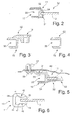
- FIG. 1 a schematic side view of the disk unit on a vehicle on the outside
- FIG. 2 a guide web of the disk unit in cross section according to section II-II of FIG. 1 .
- FIG. 3 the guide web of the disk unit in cross section according to section III-III of FIG. 1 .
- FIG. 4 the guide web of the disk unit in cross section according to section IV-IV of FIG. 1 .
- FIG. 5 the guide web of the disk unit in cross-section according to section VV of FIG. 1 .
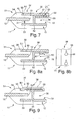
- FIG. 6 a frame surrounding a disc of the disc unit Cross section vertical longitudinal direction
- FIG. 7 Alternative embodiments of the guide web of the disk unit in cross section perpendicular to the longitudinal axis of the web according to section II-II in FIG. 1 .
- FIG. 8 a further alternative embodiment of the guide web of the disk unit in cross-section to the longitudinal axis of the guide web according to section II-II in FIG. 1 and
- FIG. 9 a further alternative embodiment of the guide web to the disk unit in cross section perpendicular to the longitudinal axis of the guide web according to section II-II in FIG. 1 ,
- a disk unit 51 is shown in a side view of the outside of the vehicle.
- This disk unit 51 comprises a first disk 12 which, for example, is fixedly mountable in the rear door of a motor vehicle.
- the first disc 12 is assigned to the vertical end face 13 of a second movable up and down disc 14.
- the disk 12 or the disk 14 may be made of silicate glass, acrylic glass or the like.
- the first disc 12 includes an encapsulation 16, which completely surrounds the triangular disc 12 in the exemplary embodiment.
- the encapsulation 16 does not completely surround the disk 12, that is to say it is not formed completely encircling, but comprises only individual side sections.
- the encapsulation 16 forms a frame 11, in which a window guide web 15 is integrated, as described below with reference to FIG FIGS. 2 to 5 is shown in more detail.
- the frame 11 is preferably made of a 2K overmoulding with two profile parts 52, 54, namely the primary part 52 of a hard component and the secondary part 54 of a soft component, wherein the soft component has a lower dimensional stability than the hard component includes.
- the secondary part 54 In the in FIG. 2 illustrated section surrounds the secondary part 54, the primary part fully. Only provided in the guide web 15 window guide 35, which is designed as a U-profile is not covered by the secondary part 54. Alternatively it can be provided that on a inner side 31 of the disk unit 51, a secondary part 54 is not provided. On the opposite outer side 32, the secondary part 54 preferably directly adjoins the disk 12 and seals it off. This is preferably advantageous if the primary part 52 is molded onto the pane 12 only without first applying a primer or adhesive.
- the guide web 15 is formed as part of the frame 11. This cross section in FIG. 2 shows that the guide web 15 and the frame 11 and the primary part 52 of the frame 11 are integrated with each other and consist of the hard component. The guide web 15 is formed almost simultaneously with the production of the primary part 52.
- materials for the encapsulation 16 for example, as the hard component for the primary part 52 and as the soft component for the secondary part 54 materials are selected, which are exemplified in the EP 0 857 116 E1 are described.
- FIG. 3 is the guide bar 15 in cross section according to section III-III of FIG. 1 shown.
- the cut passes through the guide web 15 and a fastening means 18.
- the section III-III is outside the visible range of the disk unit 51 in the installed state.
- the guide web 15 is made exclusively of the hard component.
- the fastening means 18 is formed, for example, as a mounting hole or clip holder from the component and formed directly on the guide web 15.
- This embodiment has the advantage that a further rationalization in the production is possible.
- the encapsulation of the guide web from the primary part 52 to the secondary part 54 may be provided, in particular, if in addition a damping or sealing effect is still to be achieved with.
- FIG. 4 shows a sectional view along the section IV-IV in FIG. 1 ,
- the primary part 52 exclusively forms the guide web 15 with the window guide 35.
- FIG. 5 is another connection point for fixing the disk unit 51 to the body in section VV according to FIG. 1 shown.
- This section shows a part of the disc 12, which is surrounded by the primary part 52 to form the encapsulation 16.
- the secondary part 54 is molded onto the primary part 52 in order to meet the optical requirements.
- the secondary part 54 designed as a soft component, corresponding flat or glossy surfaces with a high design quality can be formed.
- a fastening means 18 is formed directly, which also consists of the hard component.
- the outside of this web 55 is formed without secondary part 54, since this has directly to the body 40 and is not visible to the outside.
- the fastening means 18 can serve for example for receiving a fastening element 39, in particular a screw, which can be fastened in a clip 37 inserted into the body 40.
- window guide 35 for receiving the movable disc 14 is not shown in detail. This is attached by clamping, gluing or clipping in it.
- This window guide element also serves as a seal to the movable disc 14th
- FIG. 6 an alternative embodiment of a frame 11 of an encapsulation 16 for the disc 12 is shown.
- the primary part 52 is injection-molded directly onto the pane 12, without using an adhesive or a primer, in order to adhere the primary part 52 to the area surrounding the pane edge.
- a concave recess 41 is provided for sealing on an outer side or on both outer sides of the primary part 52, via which the secondary part 54 extends and forms a bead 42 which engages in the recess 41.
- the secondary part 54 does not extend directly to the disk 12 and covers the region of the primary part 52 directly adjacent to the disk 12.
- FIG. 7 is an alternative embodiment of the disk unit 51 in cross section perpendicular to the longitudinal axis of the guide web 15 according to section II-II in FIG. 1 shown.
- the outer side 32 of the disk unit 51 is formed by means of a subsequently applicable aperture element 17.
- the primary part 52 may be designed to act directly on the disk 12 in analogy to the preceding embodiment.
- a mounting opening 45 is provided in a web 55 of the guide web 15, on which the diaphragm element 17 can engage via a latching element.
- the panel member 17 in this case has a U-shaped end portion whose inner side engages completely in the window guide 35 and forms a U-shaped window guide.
- this panel member 17 by pushing on the primary part 52, which also forms the guide web 15 at the same time, pushed and fixed in a receiving area 38.
- the operating element 17 can directly adjoin the secondary part 54, so that a visually appealing arrangement is created.
- the secondary part 54 may also partially overlap the end 47 in order to hold down this end 47 of the diaphragm element 17, so that a firm abutment against the primary part 52 is provided.
- FIG. 8 an alternative embodiment of a disc unit 51 is shown with an adjacently arranged on an outer side 32 of the frame 11 panel member 17.
- the primary part 52 is not opposite to both side surfaces of the disc 12 extends at the edge region, but only on a side surface and on an end face of the disc 12 rests and attacks.
- This alternative embodiment can also be provided for the embodiment described above as well as for the embodiment to be described below.
- This panel element 17 is provided by an alternative mounting option FIG. 7 attached to the guide bar 15.
- a so-called keyhole lock 50 may be provided, in which a lock pin 57 or a plurality of lock pins 57 arranged on the inside of the cover element 17 is inserted into a fastening opening 56 formed as a keyhole, as in FIG FIG. 8b is shown, intervene.
- FIG. 9 is another alternative embodiment to the FIGS. 7 and 8 shown.
- the diaphragm element 17 is fastened to the primary part 52, for example via a double-sided adhesive tape or adhesive bond 48.
- the diaphragm element 17 itself can overlap, for example, the front end of a web 55 of the guide web to form a visually appealing transition to the movable disk 14.
- This embodiment may also be provided in the above embodiments.
- a disk unit 51 according to the invention in which the guide web 15 is also made of the hard component as the primary part 52, thus allows for the design of the visible side of the guide web 15 through the secondary part 54 in a two-component or multi-component injection molding or subsequent attachment and application of a diaphragm element 17th
- the disk unit 51 is produced in all embodiments described above in that the guide web 15 is injection molded as a hard component simultaneously with the primary part 52 to the first disc 12, wherein the injection process of the secondary part 54 then takes place as a soft component in the second step.
- the primary part 52 and the guide web 15 are produced separately from the hard component in an injection process simultaneously or successively, so that then in a second step by the secondary part 54 of the guide web 15 and the primary part 52, which is a portion of the frame 11th form for the disc 12, are connected together.
- This arrangement is also possible and has the advantage that a separate production of the guide web 15 and a separate insertion into an injection mold are dispensable.
Landscapes
- Engineering & Computer Science (AREA)
- Mechanical Engineering (AREA)
- Injection Moulding Of Plastics Or The Like (AREA)
- Window Of Vehicle (AREA)
- Seal Device For Vehicle (AREA)
Abstract
Description
- Die Erfindung betrifft eine Scheibeneinheit für Fenster an Kraftfahrzeugen und dergleichen mit einer ersten Scheibe, welche zumindest teilweise von einem Rahmen mit einem Rahmenprofil umgeben ist, wobei der Rahmen aus zwei Profilteilen mit einem Primärteil und einem Sekundärteil besteht, wobei das Primärteil als Hartkomponente ausgebildet ist, dessen Formfestigkeit größer als diejenige des als Weichkomponente ausgebildeten Sekundärteils ist.
- Aus der
EP 0 857 116 B1 ist eine Scheibeneinheit für Fenster von Kraftfahrzeugen und dergleichen bekannt, welche mit einem Rahmen aus Kunststoff versehen ist, welcher ein bestimmtes Querschnittsprofil hat. Diese Scheibeneinheit wird mit Hilfe ihres Rahmens in eine vorbestimmte Öffnung des Kraftfahrzeuges eingesetzt und darin befestigt. Der Rahmen wird aus zwei Profilteilen gebildet, von denen der primäre Profilteil den Randbereich der Glasscheibe auf drei Seiten formschlüssig umgibt. Der Rahmen wird durch Einspritzen eines Kunststoffes für den primären Profilteil um die Scheibe hergestellt. Anschließend wird auf das Primärteil ein sekundäres Profilteil mit weiteren Profilabschnitten aufgebracht, so dass eine 2-Komponenten-Umspritzung der Scheibe gegeben ist. Das Sekundärteil weist eine geringere Formfestigkeit seines Werkstoffes als das Primärteil auf und ist ausreichend nachgiebig, um anschmiegsame Dichtungsleisten zu bilden. Nachteilig bei dieser Scheibenanordnung ist, dass zur Herstellung einer Scheibeneinheit mit einem Führungssteg ein zuvor ein in ein Spritzgusswerkzeug separat hergestellter Führungssteg nach dem Anbringen des Primärteils an der Scheibe in ein weiteres Spritzgusswerkzeug eingelegt werden muss, damit über das Sekundärteil der Führungssteg fest zur Scheibeneinheit verbunden ist. - Eine weitere bekannte Scheibenanordnung ist aus der
JP 2001-071752 A - Aufgabe der Erfindung ist es daher, eine Scheibeneinheit zur Verfügung zu stellen, mit welcher die Herstellung und die Montage der Scheibe mit einer Fensterführung vereinfacht werden. Außerdem betrifft die Erfindung ein Verfahren zu dessen Herstellung.
- Eine Lösung wird durch die Merkmale des Anspruch 1 bereitgestellt. Alternative Ausführungsformen sind in den Unteransprüchen beschrieben.
- Bei der erfindungsgemäßen Scheibeneinheit ist vorgesehen, dass das Primärteil entlang einer Längsseite der ersten Scheibe als Führungssteg ausgebildet ist, der zur Scheibe weisend daran angreifend angeordnet oder angespritzt ist und gegenüberliegend eine Fensterführung zur verschiebbaren Anordnung einer bewegbaren zweiten Scheibe aufweist. Dadurch, dass der Führungssteg einstückig mit der Hartkomponente der Umspritzung der ersten Scheibe gebildet ist, kann eine erhebliche Vereinfachung in der Herstellung erfolgen. Zum einen ist eine gesonderte Herstellung des Führungssteges in einem extra Arbeitsgang nicht erforderlich, und zum anderen ist darüber hinaus entbehrlich, dass dieser separate Führungssteg in das Spritzgusswerkzeug eingelegt wird, bevor das Primärteil als Hartkomponente an die Scheibe angespritzt oder das Sekundärteil angespritzt wird.
- Als vorteilhafte Weiterbildung der Erfindung ist vorgesehen, dass außerhalb eines Sichtbereiches der festen Scheibe im eingebauten Zustand der Scheibeneinheit Befestigungselemente aus der Hartkomponente ausgebildet sind, welche an dem Führungssteg angeformt sind. Dabei kann es sich um Befestigungsbohrungen handeln, welche eine Fixierung mit weiteren Befestigungselementen an der Karosserie ermöglichen oder auch um eingelegte Befestigungsteile, wie Schrauben, Gewinde oder dergleichen handeln, womit die Fixierung an der Karosserie erzielt werden kann. Ergänzend können im äußeren Randbereich benachbart zur Umspritzung ein oder mehrere Hakenelemente aus der Hartkomponente vorgesehen sein. Dieses Hakenelement kann auch im Zusammenwirken mit weiteren Hakenelementen am Umfang der Umspritzung als eine so genannte Umschuhung wirken, das heißt, dass ein hintergreifendes Hakenelement ausgebildet ist, welches mit einem weiteren Hakenelement eine Befestigung bildet. Durch diese Alternativen kann des Weiteren eine Vereinfachung in der Herstellung erzielt werden, insbesondere wenn die Hartkomponente selbst ein Befestigungselement bildet.
- Eine weitere vorteilhafte Ausführungsform wird dadurch erreicht, dass das Sekundärteil des Rahmens zumindest abschnittsweise das Primärteil umgibt und im sichtbaren Bereich der Scheibeneinheit an einer Außenseite der Scheibe oder beidseitig an der Scheibe abdichtend abschließt. Unter beidseitig ist vorstehend die Innen- und die Außenseite der Scheibe zu verstehen, wobei das Sekundärteil das Primärteil beziehungsweise die Weichkomponente die Hartkomponente im Umfang vollständig oder teilweise umschließend aufnimmt. Die vorgesehenen Befestigungselemente sind im Bereich des nicht sichtbaren Bereichs der Scheibeneinheit in eingebautem Zustand angeordnet und frei von der Weichkomponente beziehungsweise dem Sekundärteil. Die Weichkomponente umgibt die Hartkomponente im sichtbaren Bereich, wobei der sichtbare Bereich in Längsrichtung unten etwas unterhalb sowie oben etwas oberhalb in der Karosserie endet. Außerhalb des sichtbaren Bereichs der Scheibeneinheit im eingebauten Zustand ist entweder ausschließlich die Hartkomponente vorgesehen, und die Hartkomponente ist unmittelbar an die Scheibe angespritzt oder die Weichkomponente ist als optisches Element und/oder Dichtungs- oder Dämpfungselement vorgesehen, beispielsweise einseitig über der Hartkomponente übergezogen oder angespritzt.
- Eine bevorzugte Ausführungsform wird dadurch erreicht, dass die Hartkomponente im Querschnitt senkrecht zur Längsachse konkave Einbuchtungen zur ersten Scheibe aufweist, die ein- oder beidseitig vorgesehen sind, welche das Sekundärteil beziehungsweise die Weichkomponente übergreifen. Das Sekundärteil übergreift beidseitig diese Einbuchtungen des Primärteils mit einer längs geführten Wulst, so dass bei einer formschlüssigen Anordnung der Hartkomponenten zur Scheibe eine zusätzliche Andruckwirkung der an der Seitenfläche der Fensterscheibe anliegenden Abschnitte des Primärteils bewirkt wird. Vorteilhaft ist dabei, dass die Abdichtwirkung des Primärteils dadurch verbessert werden kann. Dabei ist vorgesehen, dass die Einbuchtung sowohl im sichtbaren als auch im nicht sichtbaren Bereich ausgeführt und mit dem Sekundärteil kaschiert sein kann.
- Bevorzugt ist weiter vorgesehen, dass das Primärteil mittels eines Primers oder eines Klebemittels mit der ersten Scheibe verbunden ist. Der Primer oder das Klebemittel wird dabei vor dem Auftrag des Primärteils auf die Scheibe aufgebracht. Diese Ausgestaltung verbessert die Dichtwirkung ebenfalls.
- Alternativ kann vorgesehen sein, dass anstelle des Aufbringens eines Primers oder eines Klebemittels im Bereich des die Scheibe umgreifenden Rahmens das Primärteil unmittelbar an die Scheibe angespritzt wird und dass das Primärteil formschlüssig an dem Scheibenrand anliegt oder diesen umgreift und somit eine Abdichtwirkung erzielt.
- Eine bevorzugte Ausführungsform ist dadurch vorgesehen, dass der Führungssteg mit wenigstens einem nachträglich daran montierbaren Blendenelement verbindbar ist. Diese Ausführungsform ermöglicht es, gemäß den jeweiligen Dekorwünschen nach dem Einbau der ersten Scheibe mit dem Führungssteg ein entsprechendes Blendenelement nachträglich zu befestigen.
- Des Weiteren ist vorgesehen, dass der Führungssteg und/oder das Blendenelement für die Befestigung aneinander wenigstens eine umspritzungsfreie Anlagefläche und/oder einander zugeordnete korrespondiere Halteelemente aufweisen. Dabei bleibt eine Außenseite des Führungssteges frei, so dass auf die freie Außenseite des Führungssteges und gegebenenfalls einen Teil der angrenzenden Umspritzung überdeckend ein Blendenelement aufsetzbar ist. Analoges gilt im Falle, sollte eine Innenblende angebracht werden. Die Befestigung des Blendenelements am Führungssteg kann beispielsweise mit einer teilweisen Umspritzung oder durch Verklebung erfolgen. Ebenso sind Verklemmung, Verrastung, Verklipsung, Spangen oder dergleichen möglich. Darüber hinaus kann eine Verkrallung, Rastung, Clipsverbindung oder eine Schlüssellochbefestigung vorgesehen sein.
- Als vorteilhafte Ausführungsform ist vorgesehen, dass der Führungssteg und/oder das Blendenelement wenigstens eine U-förmige Führungsfläche für die Fensterführung der zweiten Scheibe bilden. Hierbei kann die Führungsfläche durch ein U-förmiges Profil in Richtung der Stirnseite der zweiten Scheibe ausgebildet sein. Alternativ oder ergänzend kann das Blendenelement mit dem Steg so zusammenwirken, dass sie zusammen ein U-förmiges Profil bilden.
- Die weitere, der Erfindung zugrunde liegende Aufgabe wird durch ein Verfahren gemäß den Merkmalen des Anspruchs 9 gelöst. Ausführungsvarianten werden durch die folgenden Unteransprüche beschrieben.
- Dies wird durch folgende Verfahrensschritte erreicht: Der Führungssteg und ein Primärteil eines Rahmens der Scheibeneinheit werden als Hartkomponente vorzugsweise gemeinsam an die erste Scheibe angespritzt. Das Primärteil wird in einem zumindest zur Außenseite des Fahrzeuges weisenden sichtbaren Bereich der Scheibeneinheit im eingebauten Zustand mit einem Sekundärteil umspritzt, welcher zumindest an der Außenseite der ersten Scheibe abdichtend aufgetragen wird. Dadurch wird ermöglicht, dass die Einbringung eines Fensterführungssteges in das Herstellungsverfahren einer Zwei- oder Mehrkomponenten-Umspritzung integriert ist und die gesonderte Herstellung eines Fensterführungssteges und Beistellung zum Einlegen in ein Spritzgusswerkzeug entbehrlich ist.
- Eine weitere bevorzugte Ausgestaltung des Verfahrens sieht vor, dass an dem Primärteil Befestigungselemente angeformt und/oder Einlegeteile integriert werden. Bevorzugt werden diese Befestigungselemente unmittelbar aus dem Primärteil ausgebildet. Es können beispielsweise Durchgangsbohrungen oder Haltelaschen mit Durchgangsbohrungen vorgesehen sein, in welche Klipse zur Befestigung an der Karosserie eingesetzt werden können. Weitere Befestigungstechniken sind ebenso denkbar, bei denen die Befestigungselemente unmittelbar aus der Hartkomponente bestehen. Ebenso können zusätzliche Einlegeteile vorgesehen werden, welche durch das Primärteil zumindest teilweise umspritzt werden, so dass diese fest integriert in der Umspritzung gehalten sind.
- Des Weiteren wird bevorzugt vorgeschlagen, dass an dem Führungssteg zumindest eine Anlagefläche umspritzungsfrei zur Anlage des Blendenelements ausgebildet wird. Durch diese vorteilhafte Ausgestaltung wird ermöglicht, dass eine Scheibeneinheit als Grundmodul ausgebildet werden kann, wobei in Abhängigkeit von Designansprüchen nachträglich eine spezifische Blende ausgewählt und an der Scheibeneinheit befestigt wird.
- Bei einer weiteren bevorzugten Ausführungsvariante ist vorgesehen, dass an den Führungssteg zumindest ein Halteelement für die Aufnahme des Blendenelements angeformt ist. Das Halteelement Verklipsung, Verkrallung, Schlüsselloch-Verrasterung, Verrasteinlegeteil, Klebung.
- Die Erfindung wird im Folgenden anhand der Zeichnungen erläutert. Es zeigen:
-
Figur 1 eine schematische Seitenansicht der Scheibeneinheit auf eine am Fahrzeug außen liegende Seite, -
Figur 2 ein Führungssteg der Scheibeneinheit im Querschnitt gemäß Schnitt II-II derFigur 1 , -
Figur 3 der Führungssteg der Scheibeneinheit im Querschnitt gemäß Schnitt III-III derFigur 1 , -
Figur 4 der Führungssteg der Scheibeneinheit im Querschnitt gemäß Schnitt IV-IV derFigur 1 , -
Figur 5 der Führungssteg der Scheibeneinheit im Querschnitt gemäß Schnitt V-V derFigur 1 , -
Figur 6 ein eine Scheibe der Scheibeneinheit umgebenden Rahmen im Querschnitt senkrecht Längsrichtung, -
Figur 7 alternative Ausführungsformen des Führungssteges der Scheibeneinheit im Querschnitt senkrecht zur Längsachse des Stegs gemäß Schnitt II-II inFigur 1 , -
Figur 8 eine weitere alternative Ausführungsform des Führungssteges der Scheibeneinheit im Querschnitt zur Längsachse des Führungssteges gemäß Schnitt II-II inFigur 1 und -
Figur 9 eine weitere alternative Ausführungsform des Führungssteges zur Scheibeneinheit im Querschnitt senkrecht zur Längsachse des Führungssteges gemäß Schnitt II-II inFigur 1 . - In
Figur 1 ist eine Scheibeneinheit 51 in seitlicher Ansicht auf die am Fahrzeug außen liegende Seite gezeigt. Diese Scheibeneinheit 51 umfasst eine erste Scheibe 12, welche beispielsweise fest in der hinteren Tür eines Kraftfahrzeugs montierbar ist. Dabei ist die erste Scheibe 12 an der vertikalen Stirnseite 13 einer zweiten auf und ab bewegbaren Scheibe 14 zugeordnet. Die Scheibe 12 oder die Scheibe 14 kann aus Silikatglas, Acrylglas oder dergleichen hergestellt sein. - Zwischen der ersten Scheibe 12 und der zweiten Scheibe 14 ist ein Führungssteg 15 angeordnet, welcher sich nach unten in die Karosserie der Tür über die Stirnseite 13 der ersten Scheibe 12 hinaus fortsetzt, um die zweite Scheibe 14 im geöffneten Zustand weitestgehend oder vollständig zu führen. Die erste Scheibe 12 umfasst eine Umspritzung 16, welche im Ausführungsbeispiel die dreiecksförmige Scheibe 12 vollständig umgibt. Alternativ kann vorgesehen sein, dass die Umspritzung 16 die Scheibe 12 nicht vollständig umgibt, also nicht vollständig umlaufend ausgebildet ist, sondern nur einzelne Seitenabschnitte umfasst. Die Umspritzung 16 bildet einen Rahmen 11, in dem ein Fensterführungssteg 15 integriert ist, wie nachfolgend anhand der
Figuren 2 bis 5 näher dargestellt ist. - Der Rahmen 11 besteht bevorzugt aus einer 2K-Umspritzung mit zwei Profilteilen 52, 54, und zwar dem Primärteil 52 aus einer Hartkomponente und dem Sekundärteil 54 aus einer Weichkomponente, wobei die Weichkomponente eine geringere Formfestigkeit als die Hartkomponente umfasst. In dem in
Figur 2 dargestellten Schnitt umgreift das Sekundärteil 54 das Primärteil vollumfänglich. Lediglich die im Führungssteg 15 vorgesehene Fensterführung 35, welche als U-Profil ausgebildet ist, ist nicht vom Sekundärteil 54 überdeckt. Alternativ kann vorgesehen sein, dass auf einer Innenseite 31 der Scheibeneinheit 51 ein Sekundärteil 54 nicht vorgesehen ist. Auf der gegenüberliegenden Außenseite 32 schließt das Sekundärteil 54 vorzugsweise unmittelbar an die Scheibe 12 an und dichtet diese ab. Dies ist bevorzugt dann von Vorteil, wenn das Primärteil 52 nur an die Scheibe 12 angespritzt wird, ohne dass zuvor ein Primer oder Klebemittel aufgetragen ist. - Der Führungssteg 15 ist als Teil des Rahmens 11 ausgebildet. Dieser Querschnitt in
Figur 2 zeigt, dass der Führungssteg 15 und der Rahmen 11 beziehungsweise das Primärteil 52 des Rahmens 11 ineinander integriert sind und aus der Hartkomponente bestehen. Der Führungssteg 15 wird quasi gleichzeitig mit der Herstellung des Primärteils 52 ausgebildet. - Als Materialien für die Umspritzung 16 werden beispielsweise als Hartkomponente für das Primärteil 52 und als Weichkomponente für das Sekundärteil 54 Materialien ausgewählt, welche beispielhaft in der
EP 0 857 116 E1 beschrieben sind. - In
Figur 3 ist der Führungssteg 15 im Querschnitt gemäß Schnitt III-III derFigur 1 gezeigt. Der Schnitt geht dabei durch den Führungssteg 15 und ein Befestigungsmittel 18. Der Schnitt III-III ist außerhalb des sichtbaren Bereiches der Scheibeneinheit 51 im eingebauten Zustand. In diesem Bereich ist der Führungssteg 15 ausschließlich aus der Hartkomponente hergestellt. Gleichzeitig ist das Befestigungsmittel 18 beispielsweise als Befestigungsbohrung oder Klipshalterung aus der Komponente ausgebildet und unmittelbar an den Führungssteg 15 angeformt. Diese Ausgestaltung weist den Vorteil auf, dass eine weitere Rationalisierung bei der Herstellung ermöglicht ist. Das Umspritzen des Führungssteges aus dem Primärteil 52 mit dem Sekundärteil 54 kann vorgesehen sein, insbesondere, wenn dabei zusätzlich eine Dämpfungs- oder Dichtungswirkung noch mit erzielt werden soll. -
Figur 4 zeigt eine Schnittdarstellung entlang des Schnittes IV-IV inFigur 1 . Das Primärteil 52 bildet ausschließlich den Führungssteg 15 mit der Fensterführung 35. - In
Figur 5 ist ein weiterer Anbindungspunkt zur Befestigung der Scheibeneinheit 51 an der Karosserie im Schnitt V-V gemäßFigur 1 dargestellt. Dieser Schnitt zeigt einen Teil der Scheibe 12, der von dem Primärteil 52 zur Bildung der Umspritzung 16 umgeben ist. An der Außenseite 32 ist das Sekundärteil 54 auf dem Primärteil 52 angespritzt, um auch den optischen Ansprüchen gerecht zu werden. Durch das als Weichkomponente ausgebildete Sekundärteil 54 können entsprechende ebene oder glänzende Oberflächen mit hoher Designqualität ausgebildet werden. An einem Steg 55 der Fensterführung 35 des Führungssteges 15 ist unmittelbar ein Befestigungsmittel 18 angeformt, welches ebenso aus der Hartkomponente besteht. Die Außenseite dieses Steges 55 ist ohne Sekundärteil 54 ausgebildet, da dieser unmittelbar zur Karosserie 40 weist und nach außen nicht sichtbar ist. Das Befestigungsmittel 18 kann beispielsweise zur Aufnahme eines Befestigungselements 39, insbesondere einer Schraube dienen, welche in einen in die Karosserie 40 eingesetzten Clip 37 befestigbar ist. - Bei den vorstehenden Schnittdarstellungen gemäß den
Figuren 2 bis 5 ist ein in die Fensterführung 35 einsetzbares Fensterführungselement zur Aufnahme der bewegbaren Scheibe 14 nicht näher dargestellt. Dieses wird durch Klemmen, Kleben oder Klipsen darin befestigt. Dieses Fensterführungselement dient gleichzeitig auch als Dichtung zur bewegbaren Scheibe 14. - In
Figur 6 ist eine alternative Ausgestaltung eines Rahmens 11 einer Umspritzung 16 für die Scheibe 12 dargestellt. Bei dieser Ausführungsform ist vorgesehen, dass das Primärteil 52 unmittelbar an die Scheibe 12 angespritzt wird, ohne dass dabei ein Klebemittel oder ein Primer verwendet wird, um das Primärteil 52 an dem den Scheibenrand umgreifenden Bereich festzukleben. Vielmehr ist zur Abdichtung an einer Außenseite oder an beiden Außenseiten des Primärteils 52 eine konkave Einbuchtung 41 vorgesehen, über welche sich das Sekundärteil 54 erstreckt und eine Wulst 42 ausbildet, die in die Einbuchtung 41 eingreift. Das Sekundärteil 54 erstreckt sich dabei jedoch nicht unmittelbar bis zur Scheibe 12 und überdeckt den unmittelbar an die Scheibe 12 angrenzenden Bereich des Primärteils 52. Durch diese Anordnung wird eine Art Klammerwirkung erzielt, wodurch die beiden an der Seitenfläche der Scheibe 12 anliegenden Abschnitte 43 des Primärteils 52 unter Druck an der Seitenfläche der Scheibe 12 anliegen und eine Abdichtwirkung erzielen. - In
Figur 7 ist eine alternative Ausführungsvariante der Scheibeneinheit 51 im Querschnitt senkrecht zur Längsachse des Führungsstegs 15 gemäß Schnitt II-II inFigur 1 dargestellt. Bei dieser Ausführungsform ist vorgesehen, dass die Außenseite 32 der Scheibeneinheit 51 mittels eines nachträglich aufbringbaren Blendenelementes 17 ausgebildet wird. Hierzu kann das Primärteil 52 in Analogie zur vorstehenden Ausführungsform unmittelbar an der Scheibe 12 angreifend ausgebildet sein. Zur Aufnahme und nachträglichen Fixierung des Blendenelementes 17 ist in einem Steg 55 des Führungssteges 15 eine Befestigungsöffnung 45 vorgesehen, an welcher das Blendenelement 17 über ein Rastelement einrasten kann. Das Blendenelement 17 weist dabei einen U-förmigen Endabschnitt auf, dessen Innenseite vollständig in die Fensterführung 35 eingreift und eine U-förmige Fensterführung bildet. Somit kann dieses Blendenelement 17 durch Aufschieben an dem Primärteil 52, das gleichzeitig auch den Führungssteg 15 bildet, aufgeschoben und in einem Aufnahmebereich 38 fixiert werden. An dem gegenüberliegenden Ende 47 kann das Bedienelement 17 unmittelbar an das Sekundärteil 54 angrenzen, so dass eine optisch ansprechende Anordnung geschaffen ist. Alternativ kann das Sekundärteil 54 auch das Ende 47 teilweise übergreifen, um dieses Ende 47 des Blendenelementes 17 nieder zu halten, so dass eine feste Anlage an dem Primärteil 52 gegeben ist. InFigur 8 ist eine alternative Ausführungsform einer Scheibeneinheit 51 mit einem nachträglich an einer Außenseite 32 des Rahmens 11 anordenbaren Blendenelement 17 dargestellt. Bei dieser alternativen Ausführungsform ist vorgesehen, dass das Primärteil 52 sich nicht gegenüber beiden Seitenflächen der Scheibe 12 am Randbereich erstreckt, sondern nur an einer Seitenfläche und an einer Stirnseite der Scheibe 12 anliegt und angreift. Diese alternative Ausgestaltung kann auch für das zuvor beschriebene Ausführungsbeispiel als auch für das nachfolgend noch zu beschreibende Ausführungsbeispiel vorgesehen sein. - Dieses Blendenelement 17 wird durch eine alternative Befestigungsmöglichkeit zu
Figur 7 am Führungssteg 15 befestigt. Beispielsweise kann ein sogenannter Schlüssellochverschluss 50 vorgesehen sein, bei dem ein auf der Innenseite des Blendenelementes 17 angeordneter Verriegelungszapfen 57 oder mehrere Verriegelungszapfen 57 in eine als Schlüsselloch ausgebildete Befestigungsöffnung 56, wie inFigur 8b dargestellt ist, eingreifen. - In
Figur 9 ist eine weitere alternative Ausführungsform zu denFiguren 7 und 8 dargestellt. Bei dieser Ausführungsform wird das Blendenelement 17 beispielsweise über ein doppelseitiges Klebeband oder eine Klebeverbindung 48 am Primärteil 52 befestigt. Das Blendenelement 17 selbst kann beispielsweise das stirnseitige Ende eines Steges 55 des Führungssteges übergreifen, um einen optisch ansprechenden Übergang zur bewegbaren Scheibe 14 zu bilden. Diese Ausgestaltung kann auch bei den vorstehenden Ausführungsformen vorgesehen sein. - Eine beliebige Kombination der einzelnen Merkmale in den
Figuren 7 bis 9 , soweit diese technisch sinnvoll sind, kann ebenso vorgesehen sein. - Die erfindungsgemäße Ausführungsform einer Scheibeneinheit 51, bei welcher der Führungssteg 15 ebenso aus der Hartkomponente wie das Primärteil 52 hergestellt ist, ermöglicht somit zum einen die Ausgestaltung der Sichtseite des Führungsstegs 15 durch das Sekundärteil 54 in einem Zwei-Komponenten- oder Mehrkomponenten-Spritzgussbauteil oder das nachträgliche Anbringen und Aufbringen eines Blendenelementes 17.
- Die Herstellung der Scheibeneinheit 51 erfolgt bei allen vorbeschriebenen Ausführungsformen dadurch, dass der Führungssteg 15 als Hartkomponente gleichzeitig mit dem Primärteil 52 an die erste Scheibe 12 angespritzt wird, wobei der Spritzvorgang des Sekundärteils 54 als Weichkomponente anschließend im zweiten Schritt erfolgt. Alternativ kann auch vorgesehen sein, dass das Primärteil 52 und der Führungssteg 15 getrennt aus der Hartkomponente in einem Spritzvorgang gleichzeitig oder nacheinander hergestellt werden, so dass anschließend in einem zweiten Schritt durch das Sekundärteil 54 der Führungssteg 15 und das Primärteil 52,welche einen Abschnitt des Rahmens 11 für die Scheibe 12 bilden, miteinander verbunden werden. Diese Anordnung ist ebenso möglich und weist den Vorteil auf, dass eine separate Herstellung des Führungssteges 15 und ein separates Einlegen in ein Spritzgusswerkzeug entbehrlich sind.
Claims (12)
- Scheibeneinheit für Fenster an Kraftfahrzeugen und dergleichen,- mit einer ersten Scheibe (12),- mit einem Rahmen (11), der ein Rahmenprofil aufweist und den Rand der Scheibe (12) an wenigstens zwei Seiten umfasst, wobei der Rahmen (11) an wenigstens zwei Seiten der Scheibe (12) angreift oder die Scheibe (12) ringförmig in sich geschlossen umgibt, und- der Rahmen (11) aus zwei Profilteilen (52, 54) mit einem Primärteil (52) und einem Sekundärteil (54) ausgebildet ist und- das Primärteil (52) als Hartkomponente ausgebildet ist, dessen Formfestigkeit größer als diejenige des als Weichkomponente ausgebildeten Sekundärteils (54) ist, dadurch gekennzeichnet, dass
das Primärteil (52) entlang einer Längsseite der ersten Scheibe (12) als Führungssteg (15) für eine zweite, darin auf und ab bewegbare Scheibe (14) ausgebildet ist, der zur ersten Scheibe (12) weisend daran angreifend angeordnet ist und gegenüberliegend eine Fensterführung (35) zur verschiebbaren Anordnung der bewegbaren zweiten Scheibe (14) aufweist. - Scheibeneinheit nach Anspruch 1, dadurch gekennzeichnet, dass außerhalb eines sichtbaren Bereiches der Scheibeneinheit (51) im eingebauten Zustand Befestigungselemente (18), vorzugsweise Bohrungen, Gewinde, Einlegeteile oder Umschuhungen, aus der Hartkomponente ausgebildet sind, welche an dem Führungssteg (15) angeformt sind.
- Scheibeneinheit nach einem oder mehreren der Ansprüche 1 oder 2, dadurch gekennzeichnet, dass das Sekundärteil (54) des Rahmens (11) zumindest abschnittsweise das Primärteil (52) umgibt und im sichtbaren Bereich der Scheibeneinheit (51) an einer Außenseite der Scheibe (12) oder beidseitig an der Scheibe (12) abdichtend abschließt.
- Scheibeneinheit nach einem oder mehreren der Ansprüche 1 bis 3, dadurch gekennzeichnet, dass das Primärteil (52) im Querschnitt senkrecht zur Längsachse konkave Einbuchtungen (41) zur ersten Scheibe (12) aufweist, die ein- oder beidseitig vorgesehen sind, welche das Sekundärteil (54) übergreifen.
- Scheibeneinheit nach einem oder mehreren der Ansprüche 1 bis 4, dadurch gekennzeichnet, dass das Primärteil (52) mittels eines Primers oder eines Klebemittels mit der ersten Scheibe (12) verbunden ist.
- Scheibeneinheit nach einem oder mehreren der Ansprüche 1 bis 5, dadurch gekennzeichnet, dass der Führungssteg (15) mit wenigstens einem nachträglich daran montierbaren Blendenelement (17) verbindbar ist.
- Scheibeneinheit nach Anspruch 6, dadurch gekennzeichnet, dass der Führungssteg (15) und/oder das Blendenelement (17) für die Befestigung aneinander wenigstens eine umspritzungsfreie Anlagefläche (30) und/oder einander zugeordnete korrespondiere Halteelemente (25) aufweisen.
- Scheibeneinheit nach einem der Ansprüche 6 oder 7, dadurch gekennzeichnet, dass der Führungssteg (15) und/oder das Blendenelement (17) wenigstens eine U-förmige Fensterführung (35) für die zweite Scheibe (14) bilden.
- Verfahren zur Herstellung einer Scheibeneinheit gemäß einem oder mehreren der Ansprüche 1 bis 8, gekennzeichnet durch folgende Verfahrensschritte: Ein Führungssteg (15) und ein Primärteil (52) eines Rahmens (11) der Scheibeneinheit (51) werden als Hartkomponente an die erste Scheibe (12) angespritzt, das Primärteil (52) wird in einem zumindest zur Außenseite des Fahrzeuges weisenden sichtbaren Bereich der Scheibeneinheit (51) mit einem Sekundärteil (54) umspritzt, welches zumindest an der Außenseite der ersten Scheibe (12) abdichtend aufgetragen wird.
- Verfahren zur Herstellung einer Scheibeneinheit nach Anspruch 9, dadurch gekennzeichnet, dass an dem Primärteil (52) Befestigungselemente (18) angeformt und/oder Einlegeteile integriert werden.
- Verfahren zur Herstellung einer Scheibeneinheit gemäß einem oder mehreren der Ansprüche 9 und 10, dadurch gekennzeichnet, dass an dem Führungssteg (15) zumindest eine Anlagefläche (30) umspritzungsfrei zur Anlage des Blendenelements (17) ausgebildet wird.
- Verfahren zur Herstellung einer Scheibeneinheit nach einem oder mehreren der Ansprüche 9 bis 11, dadurch gekennzeichnet, dass an den Führungssteg (15) Halteelemente (25) für die Aufnahme des Blendenelements (17) angeformt werden, welche vorzugsweise als Verklipsung, Verkrallung, Schlüsselloch-Verrastung oder durch wenigstens ein Einlegeteil ausgebildet oder als Klebung hergestellt werden.
Applications Claiming Priority (1)
| Application Number | Priority Date | Filing Date | Title |
|---|---|---|---|
| DE102010061103A DE102010061103A1 (de) | 2010-12-08 | 2010-12-08 | Scheibeneinheit und Verfahren zu deren Herstellung |
Publications (2)
| Publication Number | Publication Date |
|---|---|
| EP2463134A1 true EP2463134A1 (de) | 2012-06-13 |
| EP2463134B1 EP2463134B1 (de) | 2019-01-09 |
Family
ID=45063011
Family Applications (1)
| Application Number | Title | Priority Date | Filing Date |
|---|---|---|---|
| EP11190434.8A Active EP2463134B1 (de) | 2010-12-08 | 2011-11-24 | Dichtungsvorrichtung für eine Scheibeneinheit und dazugehöriges Herstellungsverfahren |
Country Status (7)
| Country | Link |
|---|---|
| US (1) | US20120167473A1 (de) |
| EP (1) | EP2463134B1 (de) |
| CN (1) | CN102529663A (de) |
| CA (1) | CA2759554A1 (de) |
| DE (1) | DE102010061103A1 (de) |
| MX (1) | MX2011013096A (de) |
| RU (1) | RU2011148980A (de) |
Cited By (6)
| Publication number | Priority date | Publication date | Assignee | Title |
|---|---|---|---|---|
| FR3002882A1 (fr) * | 2013-03-06 | 2014-09-12 | Renault Sa | Element de fixation pour ensemble comprenant un montant de vitre et un enjoliveur, et vehicule automobile correspondant. |
| EP2946955A1 (de) * | 2014-05-21 | 2015-11-25 | CQLT SaarGummi Technologies S.à.r.l. | Anordnung aus einem verbundteil und rahmenteil eines fahrzeugtürfensters |
| WO2018072869A1 (de) * | 2016-10-17 | 2018-04-26 | Cqlt Saargummi Technologies S.À.R.L. | Einrichtung zur randseitigen dichtung eines teils oder einer fensterscheibe einer fahrzeugkarosserie und verfahren zur herstellung der dichtungseinrichtung |
| WO2019016480A1 (fr) * | 2017-07-19 | 2019-01-24 | Saint-Gobain Glass France | Vitrage a rainure de coulissement et procédé de fabrication du vitrage |
| FR3100752A1 (fr) | 2019-09-18 | 2021-03-19 | Saint-Gobain Glass France | Vitrage a rainure de coulissement et procede de fabrication du vitrage. |
| US11780300B2 (en) * | 2020-02-26 | 2023-10-10 | AGC Inc. | Fixed window glass with division bar |
Families Citing this family (12)
| Publication number | Priority date | Publication date | Assignee | Title |
|---|---|---|---|---|
| DE102011012256A1 (de) * | 2011-02-24 | 2012-08-30 | Daimler Ag | Fensterelement für eine Seitentür, insbesondere eine hintere Seitentür, eines Kraftwagens |
| JP6230842B2 (ja) * | 2013-08-01 | 2017-11-15 | 西川ゴム工業株式会社 | ディビジョンバーの取付構造 |
| CN106945493B (zh) * | 2017-03-14 | 2019-10-18 | 福耀玻璃工业集团股份有限公司 | 一种车窗玻璃的包边总成 |
| DE102017216908A1 (de) * | 2017-09-25 | 2019-03-28 | Siemens Mobility GmbH | Fenstervorrichtung für ein Schienenfahrzeug |
| DE102017222067B4 (de) * | 2017-12-06 | 2024-10-24 | Bayerische Motoren Werke Aktiengesellschaft | Spiegeldreieck |
| JP7184051B2 (ja) * | 2017-12-12 | 2022-12-06 | Agc株式会社 | 樹脂製枠体付き固定ウインドウガラス、及びその製造方法 |
| DE102019127564A1 (de) * | 2019-05-02 | 2020-11-05 | Hauni Maschinenbau Gmbh | Verfahren zur Herstellung eines Verdampfers und Verdampfer für einen Inhalator |
| CN111873919B (zh) * | 2019-05-02 | 2024-07-02 | 理查德·弗里茨控股公司 | 用于机动车辆的装饰部件及其生产方法 |
| EP3795324B1 (de) * | 2019-09-18 | 2023-06-28 | Magna Engineered Glass Europe S.à.r.l. | Verfahren und vorrichtung zur herstellung eines fensterrahmens für ein fahrzeug und fensterrahmen für ein fahrzeug |
| CN113002283A (zh) * | 2021-03-05 | 2021-06-22 | 江苏奔宇车身制造有限公司 | 一种工程机械驾驶室玻璃密封条结构 |
| CN118076500A (zh) * | 2021-10-22 | 2024-05-24 | 福耀玻璃工业集团股份有限公司 | 车窗玻璃组件、汽车和车窗玻璃组件的制备方法 |
| CN120813491A (zh) * | 2023-06-06 | 2025-10-17 | 福耀玻璃工业集团股份有限公司 | 一种玻璃包边总成 |
Citations (9)
| Publication number | Priority date | Publication date | Assignee | Title |
|---|---|---|---|---|
| DE3432592A1 (de) * | 1984-09-05 | 1986-03-13 | Daimler-Benz Ag, 7000 Stuttgart | Einglasungsprofil fuer scheiben von fahrzeugen, insbesondere von kraftwagen |
| JP2001071752A (ja) | 1999-09-06 | 2001-03-21 | Shiroki Corp | 自動車のドア |
| DE20006771U1 (de) * | 2000-04-12 | 2001-08-23 | Meritor Automotive GmbH, 60314 Frankfurt | Dichtungsanordnung für eine bewegliche und eine angrenzende feststehende Fensterscheibe eines Fahrzeuges |
| EP0857116B1 (de) | 1995-10-27 | 2002-01-16 | Richard Fritz Gmbh + Co. Kg | Scheibeneinheit für fenster an kraftfahrzeugen und dergleichen |
| FR2858950A1 (fr) * | 2003-08-21 | 2005-02-25 | Hutchinson | Module d'etancheite d'une vitre fixe destine a etre monte sur une porte d'un vehicule |
| EP1690710A2 (de) * | 2005-02-11 | 2006-08-16 | Peugeot Citroen Automobiles SA | Anordnung von eingekapselten Verglasungen für ein Motorfahrzeug, Verfahren zum Installieren von solchen eingekapselten Verglasungen und Motorfahrzeug ausgerüstet mit solchen eingekappselten Verglasungen |
| JP2007276686A (ja) * | 2006-04-10 | 2007-10-25 | Nishikawa Rubber Co Ltd | リヤドアデビジョンバー及びその接続成形方法 |
| WO2008118903A1 (en) * | 2007-03-26 | 2008-10-02 | Hutchinson Sealing Systems, Inc. | Unsupported division post for automotive glass encapsulation |
| DE102007015466A1 (de) * | 2007-03-30 | 2008-10-02 | Metzeler Automotive Profile Systems Gmbh | Verfahren zur Herstellung einer Dichtungsanordnung, insbesondere für ein Kraftfahrzeug, mit einem Dichtungselement und einem Träger sowie eine solche Dichtungsanordnung |
Family Cites Families (20)
| Publication number | Priority date | Publication date | Assignee | Title |
|---|---|---|---|---|
| JPS60102125U (ja) * | 1983-12-19 | 1985-07-12 | トヨタ自動車株式会社 | 自動車のドア構造 |
| US4823511A (en) * | 1987-02-05 | 1989-04-25 | Libbey-Owens Ford Co. | Retention shield window assembly and method of making the same |
| FR2694243B1 (fr) * | 1992-07-29 | 1994-10-21 | Technistan Gie | Ensemble d'habillage de portière. |
| US5846463A (en) * | 1996-06-13 | 1998-12-08 | Kingston-Warren Corporation | Encapsulated fixed window module for a motor vehicle |
| US6409251B1 (en) * | 1999-05-27 | 2002-06-25 | Schlegel Corporation | Glass run surround cap |
| DE19926955B4 (de) * | 1999-06-14 | 2004-09-30 | Metzeler Automotive Profile Systems Gmbh | Stegkappe aus gummielastischem Material |
| JP3848555B2 (ja) * | 2001-10-16 | 2006-11-22 | 本田技研工業株式会社 | 車両のドアサッシュ構造 |
| JP2003260937A (ja) * | 2002-03-08 | 2003-09-16 | Nishikawa Rubber Co Ltd | 自動車ドアのドア部品組付け方法および一体化部品 |
| US6817651B2 (en) * | 2002-05-01 | 2004-11-16 | Schlegel Corporation | Modular vehicular window seal assembly |
| US20050188622A1 (en) * | 2004-02-26 | 2005-09-01 | Nestell David E. | Vehicular window assembly |
| GB2411924A (en) * | 2004-03-09 | 2005-09-14 | Gencorp Property Inc | Window pane support strip |
| US20060059799A1 (en) * | 2004-08-24 | 2006-03-23 | Cooper-Standard Automotive Inc. | Invisible division bar modular assembly |
| US20060103047A1 (en) * | 2004-11-16 | 2006-05-18 | Schlegel Corporation | Vehicular division bar assembly free of structural metal |
| GB0428265D0 (en) * | 2004-12-23 | 2005-01-26 | Gdx North America Inc | Sealing or guiding assemblies and methods of making them |
| EP1843910B1 (de) * | 2004-12-23 | 2016-06-29 | Henniges Automotive Sealing Systems North America, Inc. | Dichtung oder führungseinrichtung und verfahren zur dessen herstellung |
| US20060156632A1 (en) * | 2005-01-18 | 2006-07-20 | Ruppert Gerald Y | Window surround |
| US8522481B2 (en) * | 2006-02-02 | 2013-09-03 | Ford Global Technologies | Glass run mounting assembly for a vehicle door |
| US8042303B2 (en) * | 2008-07-15 | 2011-10-25 | Toyota Motor Engineering & Manufacturing North America, Inc. | Seal having an electroactive actuator a for sliding glass window |
| JP5209534B2 (ja) * | 2009-02-23 | 2013-06-12 | アイシン精機株式会社 | フレームガーニッシュ取付構造 |
| DE202011000804U1 (de) * | 2011-04-06 | 2012-07-09 | Richard Fritz Gmbh + Co. Kg | Scheibeneinheit für Fenster an Kraftfahrzeugen |
-
2010
- 2010-12-08 DE DE102010061103A patent/DE102010061103A1/de not_active Withdrawn
-
2011
- 2011-11-24 EP EP11190434.8A patent/EP2463134B1/de active Active
- 2011-11-29 CA CA2759554A patent/CA2759554A1/en not_active Abandoned
- 2011-12-02 RU RU2011148980/11A patent/RU2011148980A/ru not_active Application Discontinuation
- 2011-12-07 CN CN2011104029804A patent/CN102529663A/zh active Pending
- 2011-12-07 US US13/313,535 patent/US20120167473A1/en not_active Abandoned
- 2011-12-07 MX MX2011013096A patent/MX2011013096A/es not_active Application Discontinuation
Patent Citations (9)
| Publication number | Priority date | Publication date | Assignee | Title |
|---|---|---|---|---|
| DE3432592A1 (de) * | 1984-09-05 | 1986-03-13 | Daimler-Benz Ag, 7000 Stuttgart | Einglasungsprofil fuer scheiben von fahrzeugen, insbesondere von kraftwagen |
| EP0857116B1 (de) | 1995-10-27 | 2002-01-16 | Richard Fritz Gmbh + Co. Kg | Scheibeneinheit für fenster an kraftfahrzeugen und dergleichen |
| JP2001071752A (ja) | 1999-09-06 | 2001-03-21 | Shiroki Corp | 自動車のドア |
| DE20006771U1 (de) * | 2000-04-12 | 2001-08-23 | Meritor Automotive GmbH, 60314 Frankfurt | Dichtungsanordnung für eine bewegliche und eine angrenzende feststehende Fensterscheibe eines Fahrzeuges |
| FR2858950A1 (fr) * | 2003-08-21 | 2005-02-25 | Hutchinson | Module d'etancheite d'une vitre fixe destine a etre monte sur une porte d'un vehicule |
| EP1690710A2 (de) * | 2005-02-11 | 2006-08-16 | Peugeot Citroen Automobiles SA | Anordnung von eingekapselten Verglasungen für ein Motorfahrzeug, Verfahren zum Installieren von solchen eingekapselten Verglasungen und Motorfahrzeug ausgerüstet mit solchen eingekappselten Verglasungen |
| JP2007276686A (ja) * | 2006-04-10 | 2007-10-25 | Nishikawa Rubber Co Ltd | リヤドアデビジョンバー及びその接続成形方法 |
| WO2008118903A1 (en) * | 2007-03-26 | 2008-10-02 | Hutchinson Sealing Systems, Inc. | Unsupported division post for automotive glass encapsulation |
| DE102007015466A1 (de) * | 2007-03-30 | 2008-10-02 | Metzeler Automotive Profile Systems Gmbh | Verfahren zur Herstellung einer Dichtungsanordnung, insbesondere für ein Kraftfahrzeug, mit einem Dichtungselement und einem Träger sowie eine solche Dichtungsanordnung |
Cited By (10)
| Publication number | Priority date | Publication date | Assignee | Title |
|---|---|---|---|---|
| FR3002882A1 (fr) * | 2013-03-06 | 2014-09-12 | Renault Sa | Element de fixation pour ensemble comprenant un montant de vitre et un enjoliveur, et vehicule automobile correspondant. |
| EP2946955A1 (de) * | 2014-05-21 | 2015-11-25 | CQLT SaarGummi Technologies S.à.r.l. | Anordnung aus einem verbundteil und rahmenteil eines fahrzeugtürfensters |
| WO2018072869A1 (de) * | 2016-10-17 | 2018-04-26 | Cqlt Saargummi Technologies S.À.R.L. | Einrichtung zur randseitigen dichtung eines teils oder einer fensterscheibe einer fahrzeugkarosserie und verfahren zur herstellung der dichtungseinrichtung |
| US12083871B2 (en) | 2016-10-17 | 2024-09-10 | Cqlt Saargummi Technologies S.À.R.L. | Device for the edge sealing of a part or a window pane of a vehicle body and method for producing the sealing device |
| WO2019016480A1 (fr) * | 2017-07-19 | 2019-01-24 | Saint-Gobain Glass France | Vitrage a rainure de coulissement et procédé de fabrication du vitrage |
| FR3069194A1 (fr) * | 2017-07-19 | 2019-01-25 | Saint-Gobain Glass France | Vitrage a rainure de coulissement et procede de fabrication du vitrage |
| FR3100752A1 (fr) | 2019-09-18 | 2021-03-19 | Saint-Gobain Glass France | Vitrage a rainure de coulissement et procede de fabrication du vitrage. |
| WO2021053025A1 (fr) | 2019-09-18 | 2021-03-25 | Saint-Gobain Glass France | Vitrage a rainure de coulissement et procede de fabrication du vitrage |
| CN112839834A (zh) * | 2019-09-18 | 2021-05-25 | 法国圣戈班玻璃厂 | 具有滑动槽的玻璃单元和用于制造玻璃单元的方法 |
| US11780300B2 (en) * | 2020-02-26 | 2023-10-10 | AGC Inc. | Fixed window glass with division bar |
Also Published As
| Publication number | Publication date |
|---|---|
| DE102010061103A1 (de) | 2012-06-14 |
| US20120167473A1 (en) | 2012-07-05 |
| MX2011013096A (es) | 2012-06-11 |
| CN102529663A (zh) | 2012-07-04 |
| RU2011148980A (ru) | 2013-06-10 |
| CA2759554A1 (en) | 2012-06-08 |
| EP2463134B1 (de) | 2019-01-09 |
Similar Documents
| Publication | Publication Date | Title |
|---|---|---|
| EP2463134B1 (de) | Dichtungsvorrichtung für eine Scheibeneinheit und dazugehöriges Herstellungsverfahren | |
| EP2463133B1 (de) | Dichtungsanordnung für eine Scheibeneinheit | |
| EP2370282B1 (de) | U-profilelement zum verbinden einer fahrzeugscheibe mit einem wasserkasten | |
| EP2142394B1 (de) | Führungsanordnung für eine bewegbare fensterscheibe eines kraftfahrzeugs | |
| EP2285612B2 (de) | Profilelement zum verbinden einer fahrzeugscheibe mit einem wasserkasten | |
| DE102015004982A1 (de) | Befestigungsanordnung zum Positionieren und Befestigen einer Zierblende an einem Fensterrahmen einer Fahrzeugtür eines Fahrzeugs | |
| EP2272718B1 (de) | Säulenblende mit integrierter Fixierhilfe | |
| DE102012003045A1 (de) | Verfahren zur Anbringung von Funktionsbauteilen an einem Dachelement eines Fahrzeugs sowie Fahrzeugdachelement | |
| EP2113422A1 (de) | Zierteil für ein Kraftfahrzeug | |
| EP2684744A1 (de) | Zierteil für Kraftfahrzeuge und Verfahren zu seiner Herstellung | |
| DE102011050752B4 (de) | Scheibeneinheit eines Fahrzeugfensters, insbesondere eines Seitenfensters | |
| DE60320276T9 (de) | Dichtungs-, zier- oder führungsstreifen | |
| EP2492123B1 (de) | Fensterelement für eine Seitentür, insbesondere eine hintere Seitentür, eines Kraftwagens | |
| DE102014012476A1 (de) | Anbauteil zur Außenverkleidung einer Fahrzeugtür, Verfahren zu dessen Herstellung, Fahrzeugtür mit einem solchen Anbauteil und Fahrzeug mit zumindest einer solchen Fahrzeugtür | |
| EP3085563A1 (de) | Spritzgegossene wasserablaufleiste und anordnung für eine fahrzeugverkleidung | |
| DE102012023269A1 (de) | Außenspiegelanordnung für ein Kraftfahrzeug | |
| EP2305518B1 (de) | Vorrichtung für die Befestigung einer Stoßfängerverkleidung | |
| DE10213994A1 (de) | Verfahrbarer Deckel für Fahrzeugdach sowie Schiebehebedach-Modul | |
| DE102017211291B4 (de) | Fensterschachtleistenanordnung sowie Verfahren zum Herstellen einer Fensterschachtleistenanordnung | |
| DE102013223358B4 (de) | Vorrichtung zur Befestigung einer Zierleiste an einem Fahrzeugaußenhautelement, Zierleiste und Fahrzeugaußenhautelement | |
| DE102009058128A1 (de) | Rahmenblende für einen Fensterrahmen eines Fahrzeugs, Verfahren zur Herstellung und Montage einer Rahmenblende | |
| DE29807479U1 (de) | Türmodul für eine Fahrzeugtür | |
| DE102004010256B3 (de) | Dichtungsanordnung für Kraftfahrzeuge | |
| DE102004028738A1 (de) | Verfahren zur Herstellung eines Dichtungsmoduls für eine Festfensterscheibe und damit erhaltenes Modul | |
| DE202007012702U1 (de) | Aggregateträger für ein Kraftfahrzeug, insbesondere für eine Fahrzeugtür, und Fahrzeugtür |
Legal Events
| Date | Code | Title | Description |
|---|---|---|---|
| PUAI | Public reference made under article 153(3) epc to a published international application that has entered the european phase |
Free format text: ORIGINAL CODE: 0009012 |
|
| AK | Designated contracting states |
Kind code of ref document: A1 Designated state(s): AL AT BE BG CH CY CZ DE DK EE ES FI FR GB GR HR HU IE IS IT LI LT LU LV MC MK MT NL NO PL PT RO RS SE SI SK SM TR |
|
| AX | Request for extension of the european patent |
Extension state: BA ME |
|
| 17P | Request for examination filed |
Effective date: 20121213 |
|
| RAP1 | Party data changed (applicant data changed or rights of an application transferred) |
Owner name: RICHARD FRITZ HOLDING GMBH |
|
| STAA | Information on the status of an ep patent application or granted ep patent |
Free format text: STATUS: EXAMINATION IS IN PROGRESS |
|
| 17Q | First examination report despatched |
Effective date: 20161117 |
|
| REG | Reference to a national code |
Ref country code: DE Ref legal event code: R079 Ref document number: 502011015248 Country of ref document: DE Free format text: PREVIOUS MAIN CLASS: B60J0010020000 Ipc: B60J0010160000 |
|
| RIC1 | Information provided on ipc code assigned before grant |
Ipc: B60J 10/16 20160101AFI20180503BHEP Ipc: B60J 10/30 20160101ALI20180503BHEP Ipc: B60J 10/70 20160101ALI20180503BHEP Ipc: B60J 10/78 20160101ALI20180503BHEP Ipc: B60J 10/235 20160101ALI20180503BHEP |
|
| GRAP | Despatch of communication of intention to grant a patent |
Free format text: ORIGINAL CODE: EPIDOSNIGR1 |
|
| STAA | Information on the status of an ep patent application or granted ep patent |
Free format text: STATUS: GRANT OF PATENT IS INTENDED |
|
| INTG | Intention to grant announced |
Effective date: 20180712 |
|
| GRAS | Grant fee paid |
Free format text: ORIGINAL CODE: EPIDOSNIGR3 |
|
| GRAA | (expected) grant |
Free format text: ORIGINAL CODE: 0009210 |
|
| STAA | Information on the status of an ep patent application or granted ep patent |
Free format text: STATUS: THE PATENT HAS BEEN GRANTED |
|
| AK | Designated contracting states |
Kind code of ref document: B1 Designated state(s): AL AT BE BG CH CY CZ DE DK EE ES FI FR GB GR HR HU IE IS IT LI LT LU LV MC MK MT NL NO PL PT RO RS SE SI SK SM TR |
|
| REG | Reference to a national code |
Ref country code: GB Ref legal event code: FG4D Free format text: NOT ENGLISH |
|
| REG | Reference to a national code |
Ref country code: CH Ref legal event code: EP Ref country code: AT Ref legal event code: REF Ref document number: 1086838 Country of ref document: AT Kind code of ref document: T Effective date: 20190115 |
|
| REG | Reference to a national code |
Ref country code: DE Ref legal event code: R096 Ref document number: 502011015248 Country of ref document: DE |
|
| REG | Reference to a national code |
Ref country code: IE Ref legal event code: FG4D Free format text: LANGUAGE OF EP DOCUMENT: GERMAN |
|
| REG | Reference to a national code |
Ref country code: NL Ref legal event code: MP Effective date: 20190109 |
|
| REG | Reference to a national code |
Ref country code: LT Ref legal event code: MG4D |
|
| PG25 | Lapsed in a contracting state [announced via postgrant information from national office to epo] |
Ref country code: NL Free format text: LAPSE BECAUSE OF FAILURE TO SUBMIT A TRANSLATION OF THE DESCRIPTION OR TO PAY THE FEE WITHIN THE PRESCRIBED TIME-LIMIT Effective date: 20190109 |
|
| PG25 | Lapsed in a contracting state [announced via postgrant information from national office to epo] |
Ref country code: FI Free format text: LAPSE BECAUSE OF FAILURE TO SUBMIT A TRANSLATION OF THE DESCRIPTION OR TO PAY THE FEE WITHIN THE PRESCRIBED TIME-LIMIT Effective date: 20190109 Ref country code: NO Free format text: LAPSE BECAUSE OF FAILURE TO SUBMIT A TRANSLATION OF THE DESCRIPTION OR TO PAY THE FEE WITHIN THE PRESCRIBED TIME-LIMIT Effective date: 20190409 Ref country code: LT Free format text: LAPSE BECAUSE OF FAILURE TO SUBMIT A TRANSLATION OF THE DESCRIPTION OR TO PAY THE FEE WITHIN THE PRESCRIBED TIME-LIMIT Effective date: 20190109 Ref country code: ES Free format text: LAPSE BECAUSE OF FAILURE TO SUBMIT A TRANSLATION OF THE DESCRIPTION OR TO PAY THE FEE WITHIN THE PRESCRIBED TIME-LIMIT Effective date: 20190109 Ref country code: PL Free format text: LAPSE BECAUSE OF FAILURE TO SUBMIT A TRANSLATION OF THE DESCRIPTION OR TO PAY THE FEE WITHIN THE PRESCRIBED TIME-LIMIT Effective date: 20190109 Ref country code: SE Free format text: LAPSE BECAUSE OF FAILURE TO SUBMIT A TRANSLATION OF THE DESCRIPTION OR TO PAY THE FEE WITHIN THE PRESCRIBED TIME-LIMIT Effective date: 20190109 Ref country code: PT Free format text: LAPSE BECAUSE OF FAILURE TO SUBMIT A TRANSLATION OF THE DESCRIPTION OR TO PAY THE FEE WITHIN THE PRESCRIBED TIME-LIMIT Effective date: 20190509 |
|
| PG25 | Lapsed in a contracting state [announced via postgrant information from national office to epo] |
Ref country code: RS Free format text: LAPSE BECAUSE OF FAILURE TO SUBMIT A TRANSLATION OF THE DESCRIPTION OR TO PAY THE FEE WITHIN THE PRESCRIBED TIME-LIMIT Effective date: 20190109 Ref country code: LV Free format text: LAPSE BECAUSE OF FAILURE TO SUBMIT A TRANSLATION OF THE DESCRIPTION OR TO PAY THE FEE WITHIN THE PRESCRIBED TIME-LIMIT Effective date: 20190109 Ref country code: BG Free format text: LAPSE BECAUSE OF FAILURE TO SUBMIT A TRANSLATION OF THE DESCRIPTION OR TO PAY THE FEE WITHIN THE PRESCRIBED TIME-LIMIT Effective date: 20190409 Ref country code: GR Free format text: LAPSE BECAUSE OF FAILURE TO SUBMIT A TRANSLATION OF THE DESCRIPTION OR TO PAY THE FEE WITHIN THE PRESCRIBED TIME-LIMIT Effective date: 20190410 Ref country code: IS Free format text: LAPSE BECAUSE OF FAILURE TO SUBMIT A TRANSLATION OF THE DESCRIPTION OR TO PAY THE FEE WITHIN THE PRESCRIBED TIME-LIMIT Effective date: 20190509 Ref country code: HR Free format text: LAPSE BECAUSE OF FAILURE TO SUBMIT A TRANSLATION OF THE DESCRIPTION OR TO PAY THE FEE WITHIN THE PRESCRIBED TIME-LIMIT Effective date: 20190109 |
|
| REG | Reference to a national code |
Ref country code: DE Ref legal event code: R097 Ref document number: 502011015248 Country of ref document: DE |
|
| PG25 | Lapsed in a contracting state [announced via postgrant information from national office to epo] |
Ref country code: EE Free format text: LAPSE BECAUSE OF FAILURE TO SUBMIT A TRANSLATION OF THE DESCRIPTION OR TO PAY THE FEE WITHIN THE PRESCRIBED TIME-LIMIT Effective date: 20190109 Ref country code: DK Free format text: LAPSE BECAUSE OF FAILURE TO SUBMIT A TRANSLATION OF THE DESCRIPTION OR TO PAY THE FEE WITHIN THE PRESCRIBED TIME-LIMIT Effective date: 20190109 Ref country code: SK Free format text: LAPSE BECAUSE OF FAILURE TO SUBMIT A TRANSLATION OF THE DESCRIPTION OR TO PAY THE FEE WITHIN THE PRESCRIBED TIME-LIMIT Effective date: 20190109 Ref country code: AL Free format text: LAPSE BECAUSE OF FAILURE TO SUBMIT A TRANSLATION OF THE DESCRIPTION OR TO PAY THE FEE WITHIN THE PRESCRIBED TIME-LIMIT Effective date: 20190109 Ref country code: IT Free format text: LAPSE BECAUSE OF FAILURE TO SUBMIT A TRANSLATION OF THE DESCRIPTION OR TO PAY THE FEE WITHIN THE PRESCRIBED TIME-LIMIT Effective date: 20190109 Ref country code: RO Free format text: LAPSE BECAUSE OF FAILURE TO SUBMIT A TRANSLATION OF THE DESCRIPTION OR TO PAY THE FEE WITHIN THE PRESCRIBED TIME-LIMIT Effective date: 20190109 Ref country code: CZ Free format text: LAPSE BECAUSE OF FAILURE TO SUBMIT A TRANSLATION OF THE DESCRIPTION OR TO PAY THE FEE WITHIN THE PRESCRIBED TIME-LIMIT Effective date: 20190109 |
|
| PLBE | No opposition filed within time limit |
Free format text: ORIGINAL CODE: 0009261 |
|
| STAA | Information on the status of an ep patent application or granted ep patent |
Free format text: STATUS: NO OPPOSITION FILED WITHIN TIME LIMIT |
|
| PG25 | Lapsed in a contracting state [announced via postgrant information from national office to epo] |
Ref country code: SM Free format text: LAPSE BECAUSE OF FAILURE TO SUBMIT A TRANSLATION OF THE DESCRIPTION OR TO PAY THE FEE WITHIN THE PRESCRIBED TIME-LIMIT Effective date: 20190109 |
|
| 26N | No opposition filed |
Effective date: 20191010 |
|
| PG25 | Lapsed in a contracting state [announced via postgrant information from national office to epo] |
Ref country code: SI Free format text: LAPSE BECAUSE OF FAILURE TO SUBMIT A TRANSLATION OF THE DESCRIPTION OR TO PAY THE FEE WITHIN THE PRESCRIBED TIME-LIMIT Effective date: 20190109 |
|
| PG25 | Lapsed in a contracting state [announced via postgrant information from national office to epo] |
Ref country code: TR Free format text: LAPSE BECAUSE OF FAILURE TO SUBMIT A TRANSLATION OF THE DESCRIPTION OR TO PAY THE FEE WITHIN THE PRESCRIBED TIME-LIMIT Effective date: 20190109 |
|
| REG | Reference to a national code |
Ref country code: CH Ref legal event code: PL |
|
| PG25 | Lapsed in a contracting state [announced via postgrant information from national office to epo] |
Ref country code: LI Free format text: LAPSE BECAUSE OF NON-PAYMENT OF DUE FEES Effective date: 20191130 Ref country code: CH Free format text: LAPSE BECAUSE OF NON-PAYMENT OF DUE FEES Effective date: 20191130 Ref country code: MC Free format text: LAPSE BECAUSE OF FAILURE TO SUBMIT A TRANSLATION OF THE DESCRIPTION OR TO PAY THE FEE WITHIN THE PRESCRIBED TIME-LIMIT Effective date: 20190109 Ref country code: LU Free format text: LAPSE BECAUSE OF NON-PAYMENT OF DUE FEES Effective date: 20191124 |
|
| REG | Reference to a national code |
Ref country code: BE Ref legal event code: MM Effective date: 20191130 |
|
| GBPC | Gb: european patent ceased through non-payment of renewal fee |
Effective date: 20191124 |
|
| PG25 | Lapsed in a contracting state [announced via postgrant information from national office to epo] |
Ref country code: FR Free format text: LAPSE BECAUSE OF NON-PAYMENT OF DUE FEES Effective date: 20191130 Ref country code: GB Free format text: LAPSE BECAUSE OF NON-PAYMENT OF DUE FEES Effective date: 20191124 Ref country code: IE Free format text: LAPSE BECAUSE OF NON-PAYMENT OF DUE FEES Effective date: 20191124 |
|
| PG25 | Lapsed in a contracting state [announced via postgrant information from national office to epo] |
Ref country code: BE Free format text: LAPSE BECAUSE OF NON-PAYMENT OF DUE FEES Effective date: 20191130 |
|
| REG | Reference to a national code |
Ref country code: AT Ref legal event code: MM01 Ref document number: 1086838 Country of ref document: AT Kind code of ref document: T Effective date: 20191124 |
|
| PG25 | Lapsed in a contracting state [announced via postgrant information from national office to epo] |
Ref country code: AT Free format text: LAPSE BECAUSE OF NON-PAYMENT OF DUE FEES Effective date: 20191124 |
|
| PG25 | Lapsed in a contracting state [announced via postgrant information from national office to epo] |
Ref country code: CY Free format text: LAPSE BECAUSE OF FAILURE TO SUBMIT A TRANSLATION OF THE DESCRIPTION OR TO PAY THE FEE WITHIN THE PRESCRIBED TIME-LIMIT Effective date: 20190109 |
|
| PG25 | Lapsed in a contracting state [announced via postgrant information from national office to epo] |
Ref country code: MT Free format text: LAPSE BECAUSE OF FAILURE TO SUBMIT A TRANSLATION OF THE DESCRIPTION OR TO PAY THE FEE WITHIN THE PRESCRIBED TIME-LIMIT Effective date: 20190109 Ref country code: HU Free format text: LAPSE BECAUSE OF FAILURE TO SUBMIT A TRANSLATION OF THE DESCRIPTION OR TO PAY THE FEE WITHIN THE PRESCRIBED TIME-LIMIT; INVALID AB INITIO Effective date: 20111124 |
|
| PG25 | Lapsed in a contracting state [announced via postgrant information from national office to epo] |
Ref country code: MK Free format text: LAPSE BECAUSE OF FAILURE TO SUBMIT A TRANSLATION OF THE DESCRIPTION OR TO PAY THE FEE WITHIN THE PRESCRIBED TIME-LIMIT Effective date: 20190109 |
|
| P01 | Opt-out of the competence of the unified patent court (upc) registered |
Effective date: 20230522 |
|
| PGFP | Annual fee paid to national office [announced via postgrant information from national office to epo] |
Ref country code: DE Payment date: 20251112 Year of fee payment: 15 |